EP3407436B1 - Electrical connector device - Google Patents
Electrical connector device Download PDFInfo
- Publication number
- EP3407436B1 EP3407436B1 EP18173718.0A EP18173718A EP3407436B1 EP 3407436 B1 EP3407436 B1 EP 3407436B1 EP 18173718 A EP18173718 A EP 18173718A EP 3407436 B1 EP3407436 B1 EP 3407436B1
- Authority
- EP
- European Patent Office
- Prior art keywords
- connector element
- locking member
- safety locking
- connector
- elastic clip
- Prior art date
- Legal status (The legal status is an assumption and is not a legal conclusion. Google has not performed a legal analysis and makes no representation as to the accuracy of the status listed.)
- Active
Links
Images



Classifications
-
- H—ELECTRICITY
- H01—ELECTRIC ELEMENTS
- H01R—ELECTRICALLY-CONDUCTIVE CONNECTIONS; STRUCTURAL ASSOCIATIONS OF A PLURALITY OF MUTUALLY-INSULATED ELECTRICAL CONNECTING ELEMENTS; COUPLING DEVICES; CURRENT COLLECTORS
- H01R13/00—Details of coupling devices of the kinds covered by groups H01R12/70 or H01R24/00 - H01R33/00
- H01R13/62—Means for facilitating engagement or disengagement of coupling parts or for holding them in engagement
- H01R13/629—Additional means for facilitating engagement or disengagement of coupling parts, e.g. aligning or guiding means, levers, gas pressure electrical locking indicators, manufacturing tolerances
-
- H—ELECTRICITY
- H01—ELECTRIC ELEMENTS
- H01R—ELECTRICALLY-CONDUCTIVE CONNECTIONS; STRUCTURAL ASSOCIATIONS OF A PLURALITY OF MUTUALLY-INSULATED ELECTRICAL CONNECTING ELEMENTS; COUPLING DEVICES; CURRENT COLLECTORS
- H01R13/00—Details of coupling devices of the kinds covered by groups H01R12/70 or H01R24/00 - H01R33/00
- H01R13/02—Contact members
- H01R13/22—Contacts for co-operating by abutting
- H01R13/24—Contacts for co-operating by abutting resilient; resiliently-mounted
-
- H—ELECTRICITY
- H01—ELECTRIC ELEMENTS
- H01R—ELECTRICALLY-CONDUCTIVE CONNECTIONS; STRUCTURAL ASSOCIATIONS OF A PLURALITY OF MUTUALLY-INSULATED ELECTRICAL CONNECTING ELEMENTS; COUPLING DEVICES; CURRENT COLLECTORS
- H01R13/00—Details of coupling devices of the kinds covered by groups H01R12/70 or H01R24/00 - H01R33/00
- H01R13/62—Means for facilitating engagement or disengagement of coupling parts or for holding them in engagement
- H01R13/627—Snap or like fastening
- H01R13/6277—Snap or like fastening comprising annular latching means, e.g. ring snapping in an annular groove
-
- H—ELECTRICITY
- H01—ELECTRIC ELEMENTS
- H01R—ELECTRICALLY-CONDUCTIVE CONNECTIONS; STRUCTURAL ASSOCIATIONS OF A PLURALITY OF MUTUALLY-INSULATED ELECTRICAL CONNECTING ELEMENTS; COUPLING DEVICES; CURRENT COLLECTORS
- H01R13/00—Details of coupling devices of the kinds covered by groups H01R12/70 or H01R24/00 - H01R33/00
- H01R13/62—Means for facilitating engagement or disengagement of coupling parts or for holding them in engagement
- H01R13/639—Additional means for holding or locking coupling parts together, after engagement, e.g. separate keylock, retainer strap
-
- H—ELECTRICITY
- H01—ELECTRIC ELEMENTS
- H01R—ELECTRICALLY-CONDUCTIVE CONNECTIONS; STRUCTURAL ASSOCIATIONS OF A PLURALITY OF MUTUALLY-INSULATED ELECTRICAL CONNECTING ELEMENTS; COUPLING DEVICES; CURRENT COLLECTORS
- H01R13/00—Details of coupling devices of the kinds covered by groups H01R12/70 or H01R24/00 - H01R33/00
- H01R13/64—Means for preventing incorrect coupling
- H01R13/641—Means for preventing incorrect coupling by indicating incorrect coupling; by indicating correct or full engagement
Definitions
- the invention relates to the field of electrical connectors, and in particular relates to an electrical connector device comprising:
- US 5 823 813 A shows a connector with a connector position assurance.
- US 6 379 162 B1 relates to a suspension damper system.
- the object of the present invention is to implement an electrical connector device which guarantees that correct and reliable coupling between the first and the second connector element is carried out, so as to be free of operational faults caused by unintended decoupling of the two connector elements.
- a further object of the present invention is to implement a connector device which has a simple structure and a low volume and is cost-effective to produce.
- the present invention relates to an electrical connector device of the type indicated at the outset of the present description, wherein it further comprises: a safety locking member slidably mounted on said first connector element and movable between a pre-locking position and a locking position, in which said safety locking member cooperates with said elastic clip in order to prevent a displacement of said elastic clip towards its disengagement position.
- said first connector element has two guide portions for guiding said safety locking member between the pre-locking position and the locking position
- said safety locking member has two grooved portions parallel to the longitudinal axis thereof which are intended to engage with one of the two guide portions of said first connector element, wherein each of said grooved portions has a slit intended to receive an associated inclined tooth arranged on each of said guide portions of said first connector element, and each of said slits has a matching surface intended to mesh with one of said two inclined teeth, so as to prevent decoupling between said safety locking member and said first connector element.
- the safety locking member has an elastic arm having an engagement tooth which, in the pre-locking position of the safety locking member, engages in a main seat of the plastic material body of the first connector element in order to prevent the safety locking member from advancing towards said locking position.
- the body of the second connector element urges the engagement tooth of the safety locking member into a position disengaged from the matching seat, resulting in the safety locking member being free to be moved out of the locking position thereof.
- Fig. 1 is an exploded perspective view of the connector device D, which comprises a first connector element 1 and a second connector element 2 intended to be electrically connected to one another by way of mechanical operations carried out by a user.
- the connector elements 1, 2 are formed of respective plastic material bodies which carry respective electrical terminals which can be coupled to one another after the mechanical connection between the two elements 1, 2.
- the connection between the first connector element 1 and the second connector element 2 will be implemented by pressing the first connector device 1 on top of the connector device 2.
- the details of construction relating to the electrical terminals of the two connector elements 1, 2 are not represented here, since these details can be implemented in any known manner, and also because the drawings are quicker and easier to understand when these particulars are excluded.
- the connector device D further comprises an elastic clip 3 and a safety locking member 4 intended to cooperate with one another when the first connector element 1 is connected to the second connector element 2.
- the elastic clip 3 and the safety locking member 4 are both associated with the first connector element 1.
- the elastic clip 3 is mounted on the first connector element at a grooved portion 5 arranged to receive the elastic clip 3.
- the grooved portion 5 is arranged at the lower part (referring to the drawings) of the connector element 1.
- the elastic clip 3 is movable between an engagement position, in which the elastic clip 3 is coupled to the second connector element 2 to keep it coupled to the first connector element 1, and a disengagement position, which enables decoupling of the first connector 1 and the second connector 2.
- the elastic clip 3 is coupled to the second connector element 2 so as to keep the latter coupled to the first connector element 1. Further details relating to the disengagement position and engagement position of the elastic clip will be further described in the rest of the present description.
- the electrical connector device D further comprises a safety locking member 4 associated with the first connector element 1.
- the safety locking member 4 is arranged to perform the known function of a CPA ("connection position assurance") device, in other words to ensure correct coupling of the connector element with which it is associated to its counterpart.
- CPA connection position assurance
- the safety locking member 4 is mounted slidably on the first connector element 1 between a main seat 6 arranged on the body of the first connector device 1 ( Fig. 1 and 5 ).
- the main seat 6 has a matching seat 8 and an end-of-travel seat 10 arranged to cooperate with the safety locking member 4.
- the safety locking member 4 has a front face 45 intended to be pressed by a user to cause the safety locking member to slide into the main seat 6 so as to move the safety locking member 4 between a pre-locking position and a locking position.
- the rear face of the safety locking member 4, which comes into contact with the main seat 6 of the first connector element 1, has a central elastic arm 46, at the lower end of which an engagement tooth 44 is provided.
- the engagement tooth 44 is intended to engage in the end-of-travel seat 10 arranged at the lower part (referring to Fig. 1 ) of the main seat 6 of the first connector element 1.
- the safety locking member 4 further has two mutually parallel grooved portions 43 defined by respective arms 40 arranged on the sides of the central elastic arm 46.
- the grooved portions 43 are intended to engage with respective guide portions 7 of the first connector element 1 (sectional view of Fig. 5 ).
- the grooved portions 43 each have an associated slit 41, said slits each being arranged, as will be explained further, to receive an associated inclined tooth 9 arranged on each guide portion 7 of the first connector element 1.
- the safety locking member 4 when the first connector element 1 is decoupled from the second connector element 2, the safety locking member 4 is not displaceable from the pre-locking position thereof to the locking position thereof.
- the engagement tooth 44 meshes with the matching seat 8 arranged in the main seat 6 of the first connector element 1.
- the shape of the engagement tooth 44 and the matching seat 8 it is not possible to move the safety locking member towards the locking position thereof ( Fig. 6 ) .
- the guide portions 7 of the first connector element 1 each carry an inclined tooth 9.
- Fig. 8 is a sectional view of the connector device D with the first connector element 1 coupled to the second connector element 2.
- the body of the second connector element 2 and in particular the portion 21 thereof urges the engagement tooth 44 of the safety locking organ 4 into a position remote from the matching seat 8.
- the safety locking member 4 is now free to be moved by a user from the pre-locking position thereof to the locking position thereof, by contrast with the situation explained above and shown in Fig. 6 .
- the locking tooth 44 will thus be received within the end-of-travel seat 10 of the first connector element 1.
- the elastic clip 3 mounted in the grooved portion 5 of the first connector element 1 is movable between an engagement position and a disengagement position which makes it possible to decouple the first connector element 1 and the second connector element 2.
- the elastic clip 3 is arranged to be coupled to the second connector element 2 to keep it coupled to the first connector element 1.
- the elastic clip 3 is substantially U-shaped and has a central portion 30 and two elastic branches 31.
- the elastic branches 31 each have an end portion 32, in such a way that the shape of the elastic branches 31 and of the end portions 32 results in a substantially S-shaped profile.
- Fig. 9 which shows the connector device D with the first connector element 1 coupled to the second connector element 2, it will now be discussed in depth how the safety locking member 4, in the locking position thereof, cooperates with the elastic clip 3 to prevent displacement towards the disengagement position thereof.
- the front surface 45 of the safety locking member 4 is in contact with the central portion 30 of the elastic clip 3.
- the elastic clip 3 is not free to be moved into the disengagement position thereof unless it is actually desired to release the first connector element 1 from the second connector element 2.
- To decouple the first connector element 1 from the second connector element 2 it is necessary to move the safety locking member 4 upwards (referring to the drawings) into the pre-locking position thereof.
- Fig. 9 shows the connector device D with the first connector element 1 coupled to the second connector element 2
- the connector device D guarantees that correct and reliable coupling between the first and the second connector element is carried out, so as to be free of operational faults caused by unintended decoupling of the two connector elements. Further, the structure of the electrical connector device ends up being of a simple construction, intuitive to use, low in volume and cost-efficient to produce.
Landscapes
- Details Of Connecting Devices For Male And Female Coupling (AREA)
Description
- The invention relates to the field of electrical connectors, and in particular relates to an electrical connector device comprising:
- a first connector element and a second connector element carrying respective electrical terminals having respective plastic material bodies which can be coupled to one another,
- an elastic clip associated with said first connector element, said elastic clip being movable between an engagement position, in which said elastic clip is adapted to be coupled to said second connector element to keep it coupled to said first connector element, and a disengagement position, in which said elastic clip enables decoupling of said first connector element and said second connector element.
- Electrical connector devices of the type indicated above have long been known and been placed on the market.
-
US 5 823 813 A shows a connector with a connector position assurance.US 6 379 162 B1 relates to a suspension damper system. - The object of the present invention is to implement an electrical connector device which guarantees that correct and reliable coupling between the first and the second connector element is carried out, so as to be free of operational faults caused by unintended decoupling of the two connector elements.
- A further object of the present invention is to implement a connector device which has a simple structure and a low volume and is cost-effective to produce.
- It is an object of the invention to make the operation safer.
- With a view to achieving the above objects, the present invention relates to an electrical connector device of the type indicated at the outset of the present description, wherein it further comprises:
a safety locking member slidably mounted on said first connector element and movable between a pre-locking position and a locking position, in which said safety locking member cooperates with said elastic clip in order to prevent a displacement of said elastic clip towards its disengagement position. - According to the invention said first connector element has two guide portions for guiding said safety locking member between the pre-locking position and the locking position, and said safety locking member has two grooved portions parallel to the longitudinal axis thereof which are intended to engage with one of the two guide portions of said first connector element, wherein each of said grooved portions has a slit intended to receive an associated inclined tooth arranged on each of said guide portions of said first connector element, and each of said slits has a matching surface intended to mesh with one of said two inclined teeth, so as to prevent decoupling between said safety locking member and said first connector element.
- In a preferred embodiment of the invention, the safety locking member has an elastic arm having an engagement tooth which, in the pre-locking position of the safety locking member, engages in a main seat of the plastic material body of the first connector element in order to prevent the safety locking member from advancing towards said locking position.
- In the coupled state of the first connector element and the second connector element, the body of the second connector element urges the engagement tooth of the safety locking member into a position disengaged from the matching seat, resulting in the safety locking member being free to be moved out of the locking position thereof.
- Further, still in the preferred embodiment of the invention, the elastic clip is substantially U-shaped, having a central portion and two elastic branches, the two elastic branches each having an end portion which cooperates with an associated inclined surface of the body of the first connector element, in such a way that a force applied to the central portion of the elastic clip results in the two end branches spreading after the engagement of the body of the first connector element on said inclined surfaces.
- Further features and advantages of the present invention will be apparent from the following description with reference to the accompanying drawings, which are provided purely by way of non-limiting example and in which:
-
Fig. 1 is an exploded perspective view of a preferred embodiment of the connector device according to the present invention; -
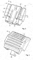
Fig. 2, 3 are two different perspective views of a safety locking member of the electrical connector device shown in the previous drawing; -
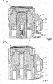
Fig. 4, 5 are two different cross-sectional views of the connector device ofFig. 1 in the mounted state thereof; and -
Fig. 6 - 9 are different sectional views of the connector device ofFig. 1 in the mounted state thereof, in different operational positions. - In the following, a preferred embodiment of an electrical connector device D according to the present invention will be described in detail in combination with the accompanying drawings.
-
Fig. 1 is an exploded perspective view of the connector device D, which comprises afirst connector element 1 and asecond connector element 2 intended to be electrically connected to one another by way of mechanical operations carried out by a user. In accordance with the prior art, theconnector elements elements first connector element 1 and thesecond connector element 2 will be implemented by pressing thefirst connector device 1 on top of theconnector device 2. The details of construction relating to the electrical terminals of the twoconnector elements - Still referring to
Fig. 1 , in accordance with an important feature of the invention, the connector device D further comprises anelastic clip 3 and asafety locking member 4 intended to cooperate with one another when thefirst connector element 1 is connected to thesecond connector element 2. In the specific embodiment shown in the drawings, theelastic clip 3 and thesafety locking member 4 are both associated with thefirst connector element 1. - In particular, the
elastic clip 3 is mounted on the first connector element at agrooved portion 5 arranged to receive theelastic clip 3. Thegrooved portion 5 is arranged at the lower part (referring to the drawings) of theconnector element 1. - As will be described further hereinafter, the
elastic clip 3 is movable between an engagement position, in which theelastic clip 3 is coupled to thesecond connector element 2 to keep it coupled to thefirst connector element 1, and a disengagement position, which enables decoupling of thefirst connector 1 and thesecond connector 2. When thefirst connector element 1 is connected to thesecond connector element 2, theelastic clip 3 is coupled to thesecond connector element 2 so as to keep the latter coupled to thefirst connector element 1. Further details relating to the disengagement position and engagement position of the elastic clip will be further described in the rest of the present description. - As stated above, the electrical connector device D further comprises a
safety locking member 4 associated with thefirst connector element 1. Thesafety locking member 4 is arranged to perform the known function of a CPA ("connection position assurance") device, in other words to ensure correct coupling of the connector element with which it is associated to its counterpart. - The
safety locking member 4 is mounted slidably on thefirst connector element 1 between amain seat 6 arranged on the body of the first connector device 1 (Fig. 1 and5 ). Themain seat 6 has a matchingseat 8 and an end-of-travel seat 10 arranged to cooperate with thesafety locking member 4. - Referring in particular to
Fig. 2, 3 , which are two perspective views of thesafety locking member 4, the shape of thelocking member 4 is now described in detail. Thesafety locking member 4 has afront face 45 intended to be pressed by a user to cause the safety locking member to slide into themain seat 6 so as to move thesafety locking member 4 between a pre-locking position and a locking position. The rear face of thesafety locking member 4, which comes into contact with themain seat 6 of thefirst connector element 1, has a centralelastic arm 46, at the lower end of which anengagement tooth 44 is provided. In the locking position of thesafety member 4, theengagement tooth 44 is intended to engage in the end-of-travel seat 10 arranged at the lower part (referring toFig. 1 ) of themain seat 6 of thefirst connector element 1. Thesafety locking member 4 further has two mutually parallel groovedportions 43 defined byrespective arms 40 arranged on the sides of the centralelastic arm 46. Thegrooved portions 43 are intended to engage withrespective guide portions 7 of the first connector element 1 (sectional view ofFig. 5 ). Thegrooved portions 43 each have an associatedslit 41, said slits each being arranged, as will be explained further, to receive an associatedinclined tooth 9 arranged on eachguide portion 7 of thefirst connector element 1. - In accordance with an important feature of the invention, when the
first connector element 1 is decoupled from thesecond connector element 2, thesafety locking member 4 is not displaceable from the pre-locking position thereof to the locking position thereof. Specifically, referring in particular to the sectional view ofFig. 6 , in the pre-locking position of thesafety locking member 4 theengagement tooth 44 meshes with the matchingseat 8 arranged in themain seat 6 of thefirst connector element 1. As a result of the shape of theengagement tooth 44 and the matchingseat 8, it is not possible to move the safety locking member towards the locking position thereof (Fig. 6 ) . - As stated above, the
guide portions 7 of thefirst connector element 1 each carry aninclined tooth 9. - Still referring to
Fig. 1 , but also toFig. 7 , which is a sectional view of the device D with thesafety locking member 4 in the pre-locking position thereof, in the pre-locking position of thesafety locking member 4 theinclined teeth 9 mesh with respectivematching surfaces 42 provided in theslits 41 of thesafety locking member 4. As a result of the meshing between eachinclined tooth 9 and the associatedmatching surface 42, thesafety locking member 4 cannot be decoupled from thefirst connector element 1 on which it is slidably mounted (Fig. 7 ). -
Fig. 8 is a sectional view of the connector device D with thefirst connector element 1 coupled to thesecond connector element 2. After the coupling, the body of thesecond connector element 2 and in particular theportion 21 thereof urges theengagement tooth 44 of thesafety locking organ 4 into a position remote from the matchingseat 8. As a result of this technique, thesafety locking member 4 is now free to be moved by a user from the pre-locking position thereof to the locking position thereof, by contrast with the situation explained above and shown inFig. 6 . Thelocking tooth 44 will thus be received within the end-of-travel seat 10 of thefirst connector element 1. - As a result of these features, a user who actuates the
safety locking member 4, successfully moving it from the pre-locking position thereof to the locking position thereof, is absolutely certain that thefirst connector element 1 is correctly coupled to thesecond connector element 2. - In the following, the
elastic clip 3 intended to cooperate with thesafety locking member 4 will now be described in detail. As stated above, theelastic clip 3 mounted in thegrooved portion 5 of thefirst connector element 1 is movable between an engagement position and a disengagement position which makes it possible to decouple thefirst connector element 1 and thesecond connector element 2. Theelastic clip 3 is arranged to be coupled to thesecond connector element 2 to keep it coupled to thefirst connector element 1. Referring in particular toFig. 1 and4 , theelastic clip 3 is substantially U-shaped and has acentral portion 30 and twoelastic branches 31. Theelastic branches 31 each have anend portion 32, in such a way that the shape of theelastic branches 31 and of theend portions 32 results in a substantially S-shaped profile. Theend portions 32 each cooperate with an associatedinclined surface 20 arranged on the outer surface of thesecond connector element 2. The shape of theinclined surfaces 20 and of theend portions 32 of theelastic clip 3 is implemented in such a way that when the first connector element is coupled on top of thesecond connector element 2, theend portions 32 glide on theinclined surfaces 20 and as a result theelastic branches 31 spread in such a way that theend portions 32 of theclip 3 are arranged below theinclined surfaces 20, thus remaining locked. - To decouple the
first connector element 1 from thesecond connector element 2, it is not sufficient to perform a mechanical operation of pulling thefirst connector element 1, decoupling it from thesecond connector element 2, since theinclined surfaces 20 of theconnector device 1 lock theend portions 32 of theelastic clip 3, thus coming to prevent removal of thefirst connector element 1 from thesecond connector element 2. To remove thefirst connector element 1 from thesecond connector element 2, it is necessary to apply a pressing force to thecentral portion 30 of theelastic clip 3, causing the twoend branches 31 to spread, and thus to free theend branches 32 from theinclined surfaces 9 of thefirst connector element 1. - Referring in particular to
Fig. 9 , which shows the connector device D with thefirst connector element 1 coupled to thesecond connector element 2, it will now be discussed in depth how thesafety locking member 4, in the locking position thereof, cooperates with theelastic clip 3 to prevent displacement towards the disengagement position thereof. Thefront surface 45 of thesafety locking member 4 is in contact with thecentral portion 30 of theelastic clip 3. As a result of thesafety locking member 4 being interposed, theelastic clip 3 is not free to be moved into the disengagement position thereof unless it is actually desired to release thefirst connector element 1 from thesecond connector element 2. To decouple thefirst connector element 1 from thesecond connector element 2, it is necessary to move thesafety locking member 4 upwards (referring to the drawings) into the pre-locking position thereof. Specifically, still referring toFig. 9 , there is no surface or element or structure which prevents thesafety locking member 4 from being moved from the locking position thereof to the pre-locking position thereof. After the displacement of thesafety locking member 4 from the locking position thereof to the pre-locking position thereof, theelastic clip 3 can thus now be freely pressed by a user at thecentral portion 30 thereof so as to spread theelastic arms 31 and thus to free theend portions 32 from theinclined surfaces 20 of thesecond connector element 2. After this manoeuvre by a user, it is thus possible to decouple thefirst connector element 1 and thesecond connector element 2. As a result of all the features indicated in the description, the connector device D according to the present invention guarantees that correct and reliable coupling between the first and the second connector element is carried out, so as to be free of operational faults caused by unintended decoupling of the two connector elements. Further, the structure of the electrical connector device ends up being of a simple construction, intuitive to use, low in volume and cost-efficient to produce. - Naturally, the particulars of construction and the embodiments may vary widely from what is described and shown, without departing from the scope of the invention as defined in the following claims as a result.
Claims (4)
- Electrical connector device (D), comprising:- a first connector element (1) and a second connector element (2) carrying respective electrical terminals having respective plastic material bodies which can be coupled to one another,- an elastic clip (3) associated with said first connector element (1), said elastic clip (3) being movable between an engagement position, in which said elastic clip (3) is adapted to be coupled to said second connector element (2) to keep it coupled to said first connector element (1), and a disengagement position, in which said elastic clip (3) enables decoupling of said first connector element (1) and said second connector element (2),wherein said connector device (D) further comprises a safety locking member (4) slidably mounted on the first connector element (1) and movable between a pre-locking position and a locking position, in which said safety locking member (4) cooperates with said elastic clip (3) in order to prevent a displacement of said elastic clip (3) towards its disengagement position, wherein said first connector element (1) has two guide portions (7) for guiding said safety locking member (4) between the pre-locking position and the locking position, and in that said safety locking member (4) has two grooved portions (43) parallel to the longitudinal axis thereof which are intended to engage with one of the two guide portions (7) of said first connector element (1), characterised in that each of said grooved portions (43) has a slit (41) intended to receive an associated inclined tooth (9) arranged on each of said guide portions (7) of said first connector element (1), and in that each of said slits (41) has a matching surface (42) intended to mesh with one of said two inclined teeth (9), so as to prevent decoupling between said safety locking member (4) and said first connector element (1).
- Electrical connector device (D) according to claim 1, characterised in that said safety locking member (4) has a central elastic arm (46) having an engagement tooth (44) which, in said pre-locking position of the safety locking member (4), engages in a matching seat (8) of the plastic material body of the first connector element (1) in order to prevent advancement of said safety locking member (4) towards said locking position.
- Electrical connector device (D) according to claim 2, characterised in that, in the coupled state of said first connector element (1) and said second connector element (2), the body of said second connector element (2) urges said engagement tooth (44) of the safety locking member (4) into a position disengaged from the matching seat (8), resulting in said safety locking member (4) being free to be moved out of the locking position thereof.
- Electrical connector device according to one of claims 1 to 3, characterised in that said elastic clip (3) is substantially U-shaped, having a central portion (30) and two elastic branches (31), the two elastic branches (31) each having an end portion (32) which cooperates with an associated inclined surface (20) of the body of said second connector element (2), in such a way that a force applied to said central portion (30) of the elastic clip (3) results in the two elastic branches (31) spreading after the engagement of the body of the second connector element (2) on said inclined surfaces (20).
Applications Claiming Priority (1)
| Application Number | Priority Date | Filing Date | Title |
|---|---|---|---|
| IT102017000057099A IT201700057099A1 (en) | 2017-05-25 | 2017-05-25 | ELECTRICAL CONNECTOR DEVICE |
Publications (2)
| Publication Number | Publication Date |
|---|---|
| EP3407436A1 EP3407436A1 (en) | 2018-11-28 |
| EP3407436B1 true EP3407436B1 (en) | 2020-09-16 |
Family
ID=60294034
Family Applications (1)
| Application Number | Title | Priority Date | Filing Date |
|---|---|---|---|
| EP18173718.0A Active EP3407436B1 (en) | 2017-05-25 | 2018-05-23 | Electrical connector device |
Country Status (6)
| Country | Link |
|---|---|
| US (1) | US10461472B2 (en) |
| EP (1) | EP3407436B1 (en) |
| JP (1) | JP7126863B2 (en) |
| KR (1) | KR102558951B1 (en) |
| CN (1) | CN108963641B (en) |
| IT (1) | IT201700057099A1 (en) |
Families Citing this family (1)
| Publication number | Priority date | Publication date | Assignee | Title |
|---|---|---|---|---|
| IT201800020638A1 (en) | 2018-12-21 | 2020-06-21 | Te Connectivity Italia Distribution Srl | Coupling element for ensuring and fixing correct positioning between a first connector element and a second connector element |
Family Cites Families (13)
| Publication number | Priority date | Publication date | Assignee | Title |
|---|---|---|---|---|
| US4179179A (en) * | 1978-05-17 | 1979-12-18 | Whitaker Cable Corporation | Electrical connector having multiple terminal receptacle receiving different plugs |
| DE9410113U1 (en) * | 1994-06-22 | 1995-10-19 | Behr-Thomson Dehnstoffregler Gmbh & Co, 70806 Kornwestheim | Electrical connection for a component arranged in a liquid-carrying housing |
| EP0747592B1 (en) * | 1995-06-09 | 1999-10-20 | Sumitomo Wiring Systems, Ltd. | Connector installation structure for fuel tank |
| US5823813A (en) * | 1997-01-21 | 1998-10-20 | Itt Manufacturing Enterprises, Inc. | Connector position assurance device |
| US6379162B1 (en) * | 2000-07-27 | 2002-04-30 | Delphi Technologies, Inc. | Electrical connector system |
| ATE417387T1 (en) * | 2005-08-08 | 2008-12-15 | Reichle & De Massari Fa | SAFETY DEVICE FOR A PLUG (PATCH GUARD) |
| SG141248A1 (en) | 2006-09-08 | 2008-04-28 | Mea Technologies Pte Ltd | Electrical connector |
| JP5005498B2 (en) * | 2007-10-24 | 2012-08-22 | 日本圧着端子製造株式会社 | Latch bracket, connector housing with latch bracket and connector with latch bracket |
| US7862366B2 (en) * | 2008-10-14 | 2011-01-04 | Woodhead Industries, Inc. | Electrical connector with locking clip |
| US9325114B2 (en) * | 2010-09-01 | 2016-04-26 | Molex, Llc | Plug connector |
| US8529283B1 (en) * | 2012-02-21 | 2013-09-10 | Adtran, Inc. | Universal serial bus (USB) connector having positive retention |
| JP2014082044A (en) * | 2012-10-15 | 2014-05-08 | Sumitomo Wiring Syst Ltd | Spring lock type connector |
| DE102016109051A1 (en) * | 2015-10-21 | 2017-04-27 | Voss Automotive Gmbh | Connectors for media cables |
-
2017
- 2017-05-25 IT IT102017000057099A patent/IT201700057099A1/en unknown
-
2018
- 2018-05-23 EP EP18173718.0A patent/EP3407436B1/en active Active
- 2018-05-23 KR KR1020180058604A patent/KR102558951B1/en active Active
- 2018-05-23 JP JP2018098365A patent/JP7126863B2/en active Active
- 2018-05-24 US US15/988,540 patent/US10461472B2/en active Active
- 2018-05-25 CN CN201810516189.8A patent/CN108963641B/en active Active
Non-Patent Citations (1)
| Title |
|---|
| None * |
Also Published As
| Publication number | Publication date |
|---|---|
| CN108963641B (en) | 2021-08-10 |
| KR20180129666A (en) | 2018-12-05 |
| US10461472B2 (en) | 2019-10-29 |
| EP3407436A1 (en) | 2018-11-28 |
| KR102558951B1 (en) | 2023-07-21 |
| IT201700057099A1 (en) | 2018-11-25 |
| JP2018200870A (en) | 2018-12-20 |
| US20180342835A1 (en) | 2018-11-29 |
| JP7126863B2 (en) | 2022-08-29 |
| CN108963641A (en) | 2018-12-07 |
Similar Documents
| Publication | Publication Date | Title |
|---|---|---|
| KR101520147B1 (en) | Connector position assurance device | |
| EP2859625B1 (en) | Connector assembly and connector product | |
| US7470138B1 (en) | Connector position assurance device and connector assembly apparatus incorporating the same | |
| US4179175A (en) | Safety socket | |
| US9270055B2 (en) | Connector with vibratory connection feedback | |
| EP3120422B1 (en) | Electrical connector assembly | |
| EP2876744B1 (en) | Connector with a connector position assurance device | |
| JP3553805B2 (en) | Connector mating structure | |
| EP2947722A1 (en) | Connector assembly with male terminal protector | |
| CA2548974A1 (en) | Quick-connect coupling | |
| CN107851934B (en) | Electrical connection device with mating detection function | |
| CN103238255A (en) | Connector assembly | |
| JP5700071B2 (en) | Electrical connector housing | |
| CN109713518B (en) | Electrical connector with position assurance device | |
| EP2277240A1 (en) | Connector | |
| JP6871228B2 (en) | connector | |
| US7854618B2 (en) | Wire connector system with lock mechanism | |
| DE102019112899B3 (en) | Safely separating connector part | |
| KR101657362B1 (en) | Connector assembly having a connector position assurance member | |
| EP3407436A1 (en) | Electrical connector device | |
| KR101472703B1 (en) | Connector | |
| EP0060655B1 (en) | Electrical connector assembly | |
| WO2014150346A1 (en) | Latching connector assembly | |
| JP6891040B2 (en) | Electrical connector assembly | |
| EP4307492B1 (en) | Rugged plug and unplugging method thereof |
Legal Events
| Date | Code | Title | Description |
|---|---|---|---|
| PUAI | Public reference made under article 153(3) epc to a published international application that has entered the european phase |
Free format text: ORIGINAL CODE: 0009012 |
|
| STAA | Information on the status of an ep patent application or granted ep patent |
Free format text: STATUS: THE APPLICATION HAS BEEN PUBLISHED |
|
| AK | Designated contracting states |
Kind code of ref document: A1 Designated state(s): AL AT BE BG CH CY CZ DE DK EE ES FI FR GB GR HR HU IE IS IT LI LT LU LV MC MK MT NL NO PL PT RO RS SE SI SK SM TR |
|
| AX | Request for extension of the european patent |
Extension state: BA ME |
|
| STAA | Information on the status of an ep patent application or granted ep patent |
Free format text: STATUS: REQUEST FOR EXAMINATION WAS MADE |
|
| 17P | Request for examination filed |
Effective date: 20190528 |
|
| RBV | Designated contracting states (corrected) |
Designated state(s): AL AT BE BG CH CY CZ DE DK EE ES FI FR GB GR HR HU IE IS IT LI LT LU LV MC MK MT NL NO PL PT RO RS SE SI SK SM TR |
|
| RAP1 | Party data changed (applicant data changed or rights of an application transferred) |
Owner name: TE CONNECTIVITY ITALIA DISTRIBUTION S.R.L. |
|
| GRAP | Despatch of communication of intention to grant a patent |
Free format text: ORIGINAL CODE: EPIDOSNIGR1 |
|
| STAA | Information on the status of an ep patent application or granted ep patent |
Free format text: STATUS: GRANT OF PATENT IS INTENDED |
|
| RIC1 | Information provided on ipc code assigned before grant |
Ipc: H01R 13/639 20060101AFI20200402BHEP Ipc: H01R 13/641 20060101ALN20200402BHEP Ipc: H01R 13/627 20060101ALN20200402BHEP |
|
| INTG | Intention to grant announced |
Effective date: 20200429 |
|
| GRAS | Grant fee paid |
Free format text: ORIGINAL CODE: EPIDOSNIGR3 |
|
| GRAA | (expected) grant |
Free format text: ORIGINAL CODE: 0009210 |
|
| STAA | Information on the status of an ep patent application or granted ep patent |
Free format text: STATUS: THE PATENT HAS BEEN GRANTED |
|
| AK | Designated contracting states |
Kind code of ref document: B1 Designated state(s): AL AT BE BG CH CY CZ DE DK EE ES FI FR GB GR HR HU IE IS IT LI LT LU LV MC MK MT NL NO PL PT RO RS SE SI SK SM TR |
|
| REG | Reference to a national code |
Ref country code: GB Ref legal event code: FG4D |
|
| REG | Reference to a national code |
Ref country code: CH Ref legal event code: EP |
|
| REG | Reference to a national code |
Ref country code: DE Ref legal event code: R096 Ref document number: 602018007818 Country of ref document: DE |
|
| REG | Reference to a national code |
Ref country code: IE Ref legal event code: FG4D |
|
| REG | Reference to a national code |
Ref country code: AT Ref legal event code: REF Ref document number: 1314993 Country of ref document: AT Kind code of ref document: T Effective date: 20201015 |
|
| PG25 | Lapsed in a contracting state [announced via postgrant information from national office to epo] |
Ref country code: BG Free format text: LAPSE BECAUSE OF FAILURE TO SUBMIT A TRANSLATION OF THE DESCRIPTION OR TO PAY THE FEE WITHIN THE PRESCRIBED TIME-LIMIT Effective date: 20201216 Ref country code: SE Free format text: LAPSE BECAUSE OF FAILURE TO SUBMIT A TRANSLATION OF THE DESCRIPTION OR TO PAY THE FEE WITHIN THE PRESCRIBED TIME-LIMIT Effective date: 20200916 Ref country code: FI Free format text: LAPSE BECAUSE OF FAILURE TO SUBMIT A TRANSLATION OF THE DESCRIPTION OR TO PAY THE FEE WITHIN THE PRESCRIBED TIME-LIMIT Effective date: 20200916 Ref country code: NO Free format text: LAPSE BECAUSE OF FAILURE TO SUBMIT A TRANSLATION OF THE DESCRIPTION OR TO PAY THE FEE WITHIN THE PRESCRIBED TIME-LIMIT Effective date: 20201216 Ref country code: GR Free format text: LAPSE BECAUSE OF FAILURE TO SUBMIT A TRANSLATION OF THE DESCRIPTION OR TO PAY THE FEE WITHIN THE PRESCRIBED TIME-LIMIT Effective date: 20201217 Ref country code: HR Free format text: LAPSE BECAUSE OF FAILURE TO SUBMIT A TRANSLATION OF THE DESCRIPTION OR TO PAY THE FEE WITHIN THE PRESCRIBED TIME-LIMIT Effective date: 20200916 |
|
| REG | Reference to a national code |
Ref country code: AT Ref legal event code: MK05 Ref document number: 1314993 Country of ref document: AT Kind code of ref document: T Effective date: 20200916 |
|
| REG | Reference to a national code |
Ref country code: NL Ref legal event code: MP Effective date: 20200916 |
|
| PG25 | Lapsed in a contracting state [announced via postgrant information from national office to epo] |
Ref country code: LV Free format text: LAPSE BECAUSE OF FAILURE TO SUBMIT A TRANSLATION OF THE DESCRIPTION OR TO PAY THE FEE WITHIN THE PRESCRIBED TIME-LIMIT Effective date: 20200916 Ref country code: RS Free format text: LAPSE BECAUSE OF FAILURE TO SUBMIT A TRANSLATION OF THE DESCRIPTION OR TO PAY THE FEE WITHIN THE PRESCRIBED TIME-LIMIT Effective date: 20200916 |
|
| REG | Reference to a national code |
Ref country code: LT Ref legal event code: MG4D |
|
| PG25 | Lapsed in a contracting state [announced via postgrant information from national office to epo] |
Ref country code: LT Free format text: LAPSE BECAUSE OF FAILURE TO SUBMIT A TRANSLATION OF THE DESCRIPTION OR TO PAY THE FEE WITHIN THE PRESCRIBED TIME-LIMIT Effective date: 20200916 Ref country code: SM Free format text: LAPSE BECAUSE OF FAILURE TO SUBMIT A TRANSLATION OF THE DESCRIPTION OR TO PAY THE FEE WITHIN THE PRESCRIBED TIME-LIMIT Effective date: 20200916 Ref country code: EE Free format text: LAPSE BECAUSE OF FAILURE TO SUBMIT A TRANSLATION OF THE DESCRIPTION OR TO PAY THE FEE WITHIN THE PRESCRIBED TIME-LIMIT Effective date: 20200916 Ref country code: RO Free format text: LAPSE BECAUSE OF FAILURE TO SUBMIT A TRANSLATION OF THE DESCRIPTION OR TO PAY THE FEE WITHIN THE PRESCRIBED TIME-LIMIT Effective date: 20200916 Ref country code: PT Free format text: LAPSE BECAUSE OF FAILURE TO SUBMIT A TRANSLATION OF THE DESCRIPTION OR TO PAY THE FEE WITHIN THE PRESCRIBED TIME-LIMIT Effective date: 20210118 Ref country code: CZ Free format text: LAPSE BECAUSE OF FAILURE TO SUBMIT A TRANSLATION OF THE DESCRIPTION OR TO PAY THE FEE WITHIN THE PRESCRIBED TIME-LIMIT Effective date: 20200916 |
|
| PG25 | Lapsed in a contracting state [announced via postgrant information from national office to epo] |
Ref country code: ES Free format text: LAPSE BECAUSE OF FAILURE TO SUBMIT A TRANSLATION OF THE DESCRIPTION OR TO PAY THE FEE WITHIN THE PRESCRIBED TIME-LIMIT Effective date: 20200916 Ref country code: AL Free format text: LAPSE BECAUSE OF FAILURE TO SUBMIT A TRANSLATION OF THE DESCRIPTION OR TO PAY THE FEE WITHIN THE PRESCRIBED TIME-LIMIT Effective date: 20200916 Ref country code: AT Free format text: LAPSE BECAUSE OF FAILURE TO SUBMIT A TRANSLATION OF THE DESCRIPTION OR TO PAY THE FEE WITHIN THE PRESCRIBED TIME-LIMIT Effective date: 20200916 Ref country code: IS Free format text: LAPSE BECAUSE OF FAILURE TO SUBMIT A TRANSLATION OF THE DESCRIPTION OR TO PAY THE FEE WITHIN THE PRESCRIBED TIME-LIMIT Effective date: 20210116 Ref country code: PL Free format text: LAPSE BECAUSE OF FAILURE TO SUBMIT A TRANSLATION OF THE DESCRIPTION OR TO PAY THE FEE WITHIN THE PRESCRIBED TIME-LIMIT Effective date: 20200916 |
|
| REG | Reference to a national code |
Ref country code: DE Ref legal event code: R097 Ref document number: 602018007818 Country of ref document: DE |
|
| PG25 | Lapsed in a contracting state [announced via postgrant information from national office to epo] |
Ref country code: SK Free format text: LAPSE BECAUSE OF FAILURE TO SUBMIT A TRANSLATION OF THE DESCRIPTION OR TO PAY THE FEE WITHIN THE PRESCRIBED TIME-LIMIT Effective date: 20200916 |
|
| PLBE | No opposition filed within time limit |
Free format text: ORIGINAL CODE: 0009261 |
|
| STAA | Information on the status of an ep patent application or granted ep patent |
Free format text: STATUS: NO OPPOSITION FILED WITHIN TIME LIMIT |
|
| 26N | No opposition filed |
Effective date: 20210617 |
|
| PG25 | Lapsed in a contracting state [announced via postgrant information from national office to epo] |
Ref country code: SI Free format text: LAPSE BECAUSE OF FAILURE TO SUBMIT A TRANSLATION OF THE DESCRIPTION OR TO PAY THE FEE WITHIN THE PRESCRIBED TIME-LIMIT Effective date: 20200916 Ref country code: DK Free format text: LAPSE BECAUSE OF FAILURE TO SUBMIT A TRANSLATION OF THE DESCRIPTION OR TO PAY THE FEE WITHIN THE PRESCRIBED TIME-LIMIT Effective date: 20200916 |
|
| PG25 | Lapsed in a contracting state [announced via postgrant information from national office to epo] |
Ref country code: IT Free format text: LAPSE BECAUSE OF FAILURE TO SUBMIT A TRANSLATION OF THE DESCRIPTION OR TO PAY THE FEE WITHIN THE PRESCRIBED TIME-LIMIT Effective date: 20200916 |
|
| REG | Reference to a national code |
Ref country code: CH Ref legal event code: PL |
|
| PG25 | Lapsed in a contracting state [announced via postgrant information from national office to epo] |
Ref country code: CH Free format text: LAPSE BECAUSE OF NON-PAYMENT OF DUE FEES Effective date: 20210531 Ref country code: MC Free format text: LAPSE BECAUSE OF FAILURE TO SUBMIT A TRANSLATION OF THE DESCRIPTION OR TO PAY THE FEE WITHIN THE PRESCRIBED TIME-LIMIT Effective date: 20200916 Ref country code: LI Free format text: LAPSE BECAUSE OF NON-PAYMENT OF DUE FEES Effective date: 20210531 Ref country code: LU Free format text: LAPSE BECAUSE OF NON-PAYMENT OF DUE FEES Effective date: 20210523 |
|
| REG | Reference to a national code |
Ref country code: BE Ref legal event code: MM Effective date: 20210531 |
|
| PG25 | Lapsed in a contracting state [announced via postgrant information from national office to epo] |
Ref country code: IE Free format text: LAPSE BECAUSE OF NON-PAYMENT OF DUE FEES Effective date: 20210523 |
|
| PG25 | Lapsed in a contracting state [announced via postgrant information from national office to epo] |
Ref country code: BE Free format text: LAPSE BECAUSE OF NON-PAYMENT OF DUE FEES Effective date: 20210531 |
|
| GBPC | Gb: european patent ceased through non-payment of renewal fee |
Effective date: 20220523 |
|
| PG25 | Lapsed in a contracting state [announced via postgrant information from national office to epo] |
Ref country code: GB Free format text: LAPSE BECAUSE OF NON-PAYMENT OF DUE FEES Effective date: 20220523 |
|
| PG25 | Lapsed in a contracting state [announced via postgrant information from national office to epo] |
Ref country code: NL Free format text: LAPSE BECAUSE OF NON-PAYMENT OF DUE FEES Effective date: 20200923 Ref country code: CY Free format text: LAPSE BECAUSE OF FAILURE TO SUBMIT A TRANSLATION OF THE DESCRIPTION OR TO PAY THE FEE WITHIN THE PRESCRIBED TIME-LIMIT Effective date: 20200916 |
|
| PG25 | Lapsed in a contracting state [announced via postgrant information from national office to epo] |
Ref country code: HU Free format text: LAPSE BECAUSE OF FAILURE TO SUBMIT A TRANSLATION OF THE DESCRIPTION OR TO PAY THE FEE WITHIN THE PRESCRIBED TIME-LIMIT; INVALID AB INITIO Effective date: 20180523 |
|
| PG25 | Lapsed in a contracting state [announced via postgrant information from national office to epo] |
Ref country code: MK Free format text: LAPSE BECAUSE OF FAILURE TO SUBMIT A TRANSLATION OF THE DESCRIPTION OR TO PAY THE FEE WITHIN THE PRESCRIBED TIME-LIMIT Effective date: 20200916 |
|
| PG25 | Lapsed in a contracting state [announced via postgrant information from national office to epo] |
Ref country code: MT Free format text: LAPSE BECAUSE OF FAILURE TO SUBMIT A TRANSLATION OF THE DESCRIPTION OR TO PAY THE FEE WITHIN THE PRESCRIBED TIME-LIMIT Effective date: 20200916 |
|
| PGFP | Annual fee paid to national office [announced via postgrant information from national office to epo] |
Ref country code: DE Payment date: 20250325 Year of fee payment: 8 |
|
| PGFP | Annual fee paid to national office [announced via postgrant information from national office to epo] |
Ref country code: FR Payment date: 20250401 Year of fee payment: 8 |
|
| PG25 | Lapsed in a contracting state [announced via postgrant information from national office to epo] |
Ref country code: TR Free format text: LAPSE BECAUSE OF FAILURE TO SUBMIT A TRANSLATION OF THE DESCRIPTION OR TO PAY THE FEE WITHIN THE PRESCRIBED TIME-LIMIT Effective date: 20200916 |