EP3407321A1 - Infrared remote control range extender - Google Patents
Infrared remote control range extender Download PDFInfo
- Publication number
- EP3407321A1 EP3407321A1 EP17173089.8A EP17173089A EP3407321A1 EP 3407321 A1 EP3407321 A1 EP 3407321A1 EP 17173089 A EP17173089 A EP 17173089A EP 3407321 A1 EP3407321 A1 EP 3407321A1
- Authority
- EP
- European Patent Office
- Prior art keywords
- signal
- transceiver unit
- receiver
- remote control
- carrier frequency
- Prior art date
- Legal status (The legal status is an assumption and is not a legal conclusion. Google has not performed a legal analysis and makes no representation as to the accuracy of the status listed.)
- Granted
Links
Images


Classifications
-
- G—PHYSICS
- G08—SIGNALLING
- G08C—TRANSMISSION SYSTEMS FOR MEASURED VALUES, CONTROL OR SIMILAR SIGNALS
- G08C23/00—Non-electrical signal transmission systems, e.g. optical systems
- G08C23/04—Non-electrical signal transmission systems, e.g. optical systems using light waves, e.g. infrared
-
- G—PHYSICS
- G08—SIGNALLING
- G08C—TRANSMISSION SYSTEMS FOR MEASURED VALUES, CONTROL OR SIMILAR SIGNALS
- G08C2201/00—Transmission systems of control signals via wireless link
- G08C2201/40—Remote control systems using repeaters, converters, gateways
Definitions
- This invention refers to a system for extending range of a remote control according to claim 1, and a method according to claim 5.
- IR Infrared
- US20060210278A1 discloses remote operation of local or distant infrared-controllable and non-infrared-controllable devices.
- US20060210278A1 further discloses a system for operating infrared-controllable apparatus, said system comprising a remote control comprising circuitry for sending infrared signals; first apparatus comprising circuitry for receiving first infrared signals from said remote control, circuitry for decoding data from said first infrared signals, and circuitry for sending said data over a communications network; and second apparatus comprising circuitry for receiving said data over said communications network and circuitry for sending second infrared signals associated with said received data to said infrared-controllable apparatus.
- the second apparatus that is second extender device which transmits the repeated IR signal to the electronics device has no capability to detect whether the actual IR signal reached the IR receiver or not. If the both command signals from remote control and second extender device reached the IR receiver, then the electronics device might get unnecessary control data.
- the before mentioned object is solved by a system for extending range of a remote control according to claim 1.
- the system for extending range of a remote control according to the present invention preferably comprises at least one electronic device, a remote control, a first transceiver unit, a second transceiver unit and an infrared (IR) receiver.
- the IR receiver is provided in the electronic device for receiving the IR signal.
- the remote control can be configured for transmitting first IR signal with an original carrier frequency to the first transceiver unit for controlling the electronic device.
- the first transceiver unit can be configured for receiving first IR signal from the remote control and converting the first IR signal to a second IR signal by changing the original carrier frequency with a different carrier frequency.
- the first transceiver unit further can be configured for transmitting the second IR signal to the second transceiver unit.
- the second transceiver unit can be configured for receiving the second IR signal from the first transceiver unit and converting the second IR signal to a third IR signal by changing the received carrier frequency with the original carrier frequency.
- the second transceiver unit can be further configured for checking whether the first IR signal reached the IR receiver or not before transmitting the third IR signal.
- the second transceiver unit further configured for transmitting the third IR signal to the IR receiver in case the first IR signal not reached the IR receiver.
- the system can be implemented for any consumer electronic device which utilizes IR signals for controlling the electronic device.
- the second transceiver unit can be further configured for preventing transmission of the third IR signal to the electronic device in case the first IR signal reached the electronic device.
- the electronics device may include but is not limited to TV, audio system, DVD, set-up box, consumer electronics which are controlled by the remote control and so on.
- the system transmits the signals in the form of infrared waves.
- Said method preferably comprises the steps: transmitting first infrared (IR) signal with an original carrier frequency to a first transceiver unit for controlling an electronic device, receiving first IR signal from the remote control at the first transceiver unit, converting the first IR signal to a second IR signal by changing the original carrier frequency with a different carrier frequency, transmitting the second IR signal from the first transceiver unit to the second transceiver unit, receiving the second IR signal at the second transceiver unit from the first transceiver unit and converting the second IR signal to a third IR signal by changing the received carrier frequency with the original carrier frequency.
- IR infrared
- the method further comprising the steps of checking whether the first IR signal reached the IR receiver or not before transmitting the third IR signal from the second transceiver unit, transmitting the third IR signal to the IR receiver in case the first IR signal not reached the IR receiver and preventing transmission of the third IR signal from the second transceiver unit to the IR receiver in case the first IR signal reached the IR receiver.
- Fig. 1 illustrates a general flow diagram 100 of application of the system in TV, according to the present invention.
- the system for extending the range of a remote control 5 preferably comprises an electronic device 1 for example TV, a remote control 5, a first transceiver unit 4, a second transceiver unit 3 and an infrared (IR) receiver 2.
- the IR receiver 2 is provided in the electronic device 1 for receiving the IR signal.
- the remote control 5 transmits first IR signal 6 with an original carrier frequency to the first transceiver unit 4 for controlling the electronic device 1.
- a second IR signal 7 for example 38KHz
- the second transceiver unit 3 a third IR signal 8 is transmitted to the IR receiver 2 after changing the different carrier frequency to the original carrier frequency.
- the range of the IR remote control 5 can be increased by the first and second transceiver (or extender).
- Fig. 2 illustrates the block diagram of the system 200 for extending the range of a remote control 5, according to the present invention.
- the system for extending range of a remote control 5 preferably comprises at least one electronic device 1, a remote control 5, a first transceiver unit 4, a second transceiver unit 3 and infrared (IR) receiver 2.
- the IR receiver 2 is provided in the electronic device 1 for receiving the IR signal.
- the remote control 5 can be configured for transmitting first IR signal 6 with an original carrier frequency to the first transceiver unit 4 for controlling the electronic device 1.
- the first IR signal 6 reaches the first transceiver unit 4 and part of the IR signal 10 from the remote control 5 may also reach the IR receiver 2 with weak signal strength. Hence, the IR signal faded 9 away in a travelling path by losing the strength. Many times the IR signal from the remote control 5 cannot reach the IR receiver 2.
- the first transceiver unit 4 can be configured for receiving first IR signal 6 (for example 36KHz) from the remote control 5 and converting the first IR signal 6 to a second IR signal 7 (for example 38KHz) by changing the original carrier frequency with a different carrier frequency.
- the first transceiver unit 4 further can be configured for transmitting the second IR signal 7 to the second transceiver unit 3.
- the second transceiver unit 3 can be configured for receiving the second IR signal 7 from the first transceiver unit 4 and converting the second IR signal 7 to a third IR signal 8 by changing the received carrier frequency with the original carrier frequency.
- the second transceiver unit 3 can be further configured for checking whether the first IR signal 6 reached the IR receiver 2 or not before transmitting the third IR signal 8.
- the second transceiver unit 3 further configured for transmitting the third IR signal 8 (for example 36KHz) to the IR receiver 2 in case the first IR signal 6 not reached the IR receiver 2.
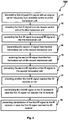
- Fig. 3 illustrates a method 300 for extending range of a remote control 5, according to the present invention.
- the method for extending range of a remote control 5 comprising the steps of:
- the present invention refers to a system and a method for extending range of a remote control 5.
- the system comprises of at least an electronic device 1, a remote control 5, a first transceiver unit 4, a second transceiver unit 3 and an infrared (IR) receiver.
- the IR receiver 2 is provided in the electronic device 1 for receiving the IR signal.
- the remote control 5 transmits first IR signal 6 to the first transceiver unit 4 for controlling the electronic device 1.
- a second IR signal 7 is transmitted to the second transceiver unit 3.
- a third IR signal 8 is transmitted to the IR receiver 2 thereby to extend the range of IR remote control 5.
- the second transceiver unit 3 also detects whether the IR signal from the remote control 5 reached the IR receiver 2 or not and transmits accordingly the IR signal from the second transceiver unit 3.
Landscapes
- Physics & Mathematics (AREA)
- General Physics & Mathematics (AREA)
- Selective Calling Equipment (AREA)
- Details Of Television Systems (AREA)
Abstract
Description
- This invention refers to a system for extending range of a remote control according to claim 1, and a method according to
claim 5. - Consumer Electronics devices (for example Television sets, Set-Top boxes, DVR's) generally controlled by a remote control system which uses Infrared (IR) signals. The Infrared remote works well for moderate distances however its performance declines when the distance increases. Further, in some cases controller devices suffer from controlling problems due to range issues. Hence, there exists a need for a remote control range extender for increasing the control area.
- Prior art document
US20060210278A1 discloses remote operation of local or distant infrared-controllable and non-infrared-controllable devices.US20060210278A1 further discloses a system for operating infrared-controllable apparatus, said system comprising a remote control comprising circuitry for sending infrared signals; first apparatus comprising circuitry for receiving first infrared signals from said remote control, circuitry for decoding data from said first infrared signals, and circuitry for sending said data over a communications network; and second apparatus comprising circuitry for receiving said data over said communications network and circuitry for sending second infrared signals associated with said received data to said infrared-controllable apparatus. - In this prior art document, the second apparatus that is second extender device which transmits the repeated IR signal to the electronics device has no capability to detect whether the actual IR signal reached the IR receiver or not. If the both command signals from remote control and second extender device reached the IR receiver, then the electronics device might get unnecessary control data.
- It is therefore the object of the present invention to provide a system, in particular a system for extending range of a remote control, and a method that has a better efficiency and increase the performance compared to the known devices and methods.
- The before mentioned object is solved by a system for extending range of a remote control according to claim 1. The system for extending range of a remote control according to the present invention preferably comprises at least one electronic device, a remote control, a first transceiver unit, a second transceiver unit and an infrared (IR) receiver. The IR receiver is provided in the electronic device for receiving the IR signal. The remote control can be configured for transmitting first IR signal with an original carrier frequency to the first transceiver unit for controlling the electronic device. The first transceiver unit can be configured for receiving first IR signal from the remote control and converting the first IR signal to a second IR signal by changing the original carrier frequency with a different carrier frequency. The first transceiver unit further can be configured for transmitting the second IR signal to the second transceiver unit. The second transceiver unit can be configured for receiving the second IR signal from the first transceiver unit and converting the second IR signal to a third IR signal by changing the received carrier frequency with the original carrier frequency. The second transceiver unit can be further configured for checking whether the first IR signal reached the IR receiver or not before transmitting the third IR signal. The second transceiver unit further configured for transmitting the third IR signal to the IR receiver in case the first IR signal not reached the IR receiver.
- This solution is beneficial since such a system for extending range of a remote control can extend IR remote control working range and also prevents the electronics device from getting unnecessary control data twice from extender and remote control.
- The system can be implemented for any consumer electronic device which utilizes IR signals for controlling the electronic device.
- Further preferred embodiments are subject-matter of dependent claims and/or of the following specification parts.
- According to a preferred embodiment of the present invention the second transceiver unit can be further configured for preventing transmission of the third IR signal to the electronic device in case the first IR signal reached the electronic device. The electronics device may include but is not limited to TV, audio system, DVD, set-up box, consumer electronics which are controlled by the remote control and so on. The system transmits the signals in the form of infrared waves.
- The before mentioned object is also solved by a method for extending range of a remote control according to
claim 5. Said method preferably comprises the steps: transmitting first infrared (IR) signal with an original carrier frequency to a first transceiver unit for controlling an electronic device, receiving first IR signal from the remote control at the first transceiver unit, converting the first IR signal to a second IR signal by changing the original carrier frequency with a different carrier frequency, transmitting the second IR signal from the first transceiver unit to the second transceiver unit, receiving the second IR signal at the second transceiver unit from the first transceiver unit and converting the second IR signal to a third IR signal by changing the received carrier frequency with the original carrier frequency. - According to a further embodiment of the present invention the method further comprising the steps of checking whether the first IR signal reached the IR receiver or not before transmitting the third IR signal from the second transceiver unit, transmitting the third IR signal to the IR receiver in case the first IR signal not reached the IR receiver and preventing transmission of the third IR signal from the second transceiver unit to the IR receiver in case the first IR signal reached the IR receiver.
- Further benefits, goals and features of the present invention will be described by the following specification of the attached figures, in which components of the invention are exemplarily illustrated. Components of the devices and method according to the inventions, which match at least essentially with respect to their function, can be marked with the same reference sign, wherein such components do not have to be marked or described in all figures.
- The invention is just exemplarily described with respect to the attached figures in the following.
-
- Fig. 1
- illustrates a general flow diagram of application of the system in TV, according to the present invention;
- Fig. 2
- illustrates the block diagram of the system for extending range of a remote control, according to the present invention; and
- Fig. 3
- illustrates a method for extending range of a remote control, according to the present invention.
-
Fig. 1 illustrates a general flow diagram 100 of application of the system in TV, according to the present invention. The system for extending the range of aremote control 5 according to the present invention preferably comprises an electronic device 1 for example TV, aremote control 5, a first transceiver unit 4, asecond transceiver unit 3 and an infrared (IR)receiver 2. TheIR receiver 2 is provided in the electronic device 1 for receiving the IR signal. Theremote control 5 transmits first IR signal 6 with an original carrier frequency to the first transceiver unit 4 for controlling the electronic device 1. From the first transceiver unit 4 a second IR signal 7 (for example 38KHz) is transmitted to thesecond transceiver unit 3, after changing the original carrier frequency with a different carrier frequency. From the second transceiver unit 3 athird IR signal 8 is transmitted to theIR receiver 2 after changing the different carrier frequency to the original carrier frequency. Thus the range of theIR remote control 5 can be increased by the first and second transceiver (or extender). -
Fig. 2 illustrates the block diagram of thesystem 200 for extending the range of aremote control 5, according to the present invention. The system for extending range of aremote control 5 according to the present invention preferably comprises at least one electronic device 1, aremote control 5, a first transceiver unit 4, asecond transceiver unit 3 and infrared (IR)receiver 2. TheIR receiver 2 is provided in the electronic device 1 for receiving the IR signal. Theremote control 5 can be configured for transmitting first IR signal 6 with an original carrier frequency to the first transceiver unit 4 for controlling the electronic device 1. The first IR signal 6 reaches the first transceiver unit 4 and part of theIR signal 10 from theremote control 5 may also reach theIR receiver 2 with weak signal strength. Hence, the IR signal faded 9 away in a travelling path by losing the strength. Many times the IR signal from theremote control 5 cannot reach theIR receiver 2. - According to a preferred embodiment of the present invention, the first transceiver unit 4 can be configured for receiving first IR signal 6 (for example 36KHz) from the
remote control 5 and converting the first IR signal 6 to a second IR signal 7 (for example 38KHz) by changing the original carrier frequency with a different carrier frequency. The first transceiver unit 4 further can be configured for transmitting thesecond IR signal 7 to thesecond transceiver unit 3. Thesecond transceiver unit 3 can be configured for receiving thesecond IR signal 7 from the first transceiver unit 4 and converting thesecond IR signal 7 to athird IR signal 8 by changing the received carrier frequency with the original carrier frequency. Thesecond transceiver unit 3 can be further configured for checking whether the first IR signal 6 reached theIR receiver 2 or not before transmitting thethird IR signal 8. Thesecond transceiver unit 3 further configured for transmitting the third IR signal 8 (for example 36KHz) to theIR receiver 2 in case the first IR signal 6 not reached theIR receiver 2. -
Fig. 3 illustrates amethod 300 for extending range of aremote control 5, according to the present invention. The method for extending range of aremote control 5 comprising the steps of: - at
block 11, the first infrared (IR) signal is transmitted with an original carrier frequency to a first transceiver unit 4 for controlling an electronic device 1; - at
block 12, the first IR signal 6 from theremote control 5 is received at the first transceiver unit 4; - at
block 13, the first IR signal 6 is converted to asecond IR signal 7 by changing the original carrier frequency with a different carrier frequency; - at
block 14, thesecond IR signal 7 from the first transceiver unit 4 is transmitted to thesecond transceiver unit 3; - at
block 15, thesecond IR signal 7 is received at thesecond transceiver unit 3 from the first transceiver unit 4; - at
block 16, thesecond IR signal 7 is converted to athird IR signal 8 by changing the received carrier frequency with the original carrier frequency; - at
block 17, thesecond transceiver unit 3 can check whether the first IR signal 6 reached theIR receiver 2 or not before transmitting thethird IR signal 8; - at
block 18, thethird IR signal 8 is transmited to theIR receiver 2 in case the first IR signal 6 not reached theIR receiver 2; and - at
block 19, the transmission of thethird IR signal 8 from thesecond transceiver unit 3 is prevented to reach theIR receiver 2 in case the first IR signal 6 reached theIR receiver 2. - Thus, the present invention refers to a system and a method for extending range of a
remote control 5. The system comprises of at least an electronic device 1, aremote control 5, a first transceiver unit 4, asecond transceiver unit 3 and an infrared (IR) receiver. TheIR receiver 2 is provided in the electronic device 1 for receiving the IR signal. Theremote control 5 transmits first IR signal 6 to the first transceiver unit 4 for controlling the electronic device 1. From the first transceiver unit 4 asecond IR signal 7 is transmitted to thesecond transceiver unit 3. From the second transceiver unit 3 athird IR signal 8 is transmitted to theIR receiver 2 thereby to extend the range of IRremote control 5. Thesecond transceiver unit 3 also detects whether the IR signal from theremote control 5 reached theIR receiver 2 or not and transmits accordingly the IR signal from thesecond transceiver unit 3. -
- 1
- electronic device
- 2
- IR receiver
- 3
- second transceiver unit
- 4
- first transceiver unit
- 5
- remote control
- 6
- first IR signal
- 7
- second IR signal
- 8
- third IR signal
- 9
- faded IR signal path
- 10
- part of the faded IR signal
- 11
- transmitting first infrared (IR) signal with an original carrier frequency from a remote control to a first transceiver unit
- 12
- receiving the first IR signal from the remote control unit at the first transceiver unit
- 13
- converting the first IR signal to a second IR signal at the first transceiver unit
- 14
- transmitting the second IR signal from the first transceiver unit to the second transceiver unit
- 15
- receiving the second IR signal from the first transceiver unit at the second transceiver unit
- 16
- converting the second IR signal to a third IR signal at the second transceiver unit
- 17
- checking whether the first IR signal reached the IR receiver or not
- 18
- transmitting the third IR signal to the IR receiver in case the first IR signal not reached the IR receiver
- 19
- preventing transmission of the third IR signal to the IR receiver in case the first IR signal reached the IR receiver
Claims (6)
- A system for extending range of a remote control comprises of
at least one electronic device (1), a remote control (5), a first transceiver unit (4), a second transceiver unit (3) and an infrared (IR) receiver (2);
wherein the IR receiver (2) is provided in the electronic device (1) for receiving the IR signal;
wherein the remote control (5) is configured for transmitting first IR signal (6) with an original carrier frequency to the first transceiver unit (4) for controlling the electronic device (1);
wherein the first transceiver unit (4) is configured for receiving first IR signal (6) from the remote control (5) and converting the first IR signal (6) to a second IR signal (7) by changing the original carrier frequency with a different carrier frequency;
wherein the first transceiver unit (4) is further configured for transmitting the second IR signal (7) to the second transceiver unit (3);
wherein the second transceiver unit (3) is configured for receiving the second IR signal (7) from the first transceiver unit (4) and converting the second IR signal (7) to a third IR signal (8) by changing the received carrier frequency with the original carrier frequency;
characterized in that
wherein the second transceiver unit (3) is further configured for checking whether the first IR signal (6) reached the IR receiver (2) or not before transmitting the third IR signal (8); and
wherein the second transceiver unit (3) is configured for transmitting the third IR signal (8) to the IR receiver (2) in case the first IR signal (6) not reached the IR receiver (2). - The system for claim 1, wherein the second transceiver unit (3) is further configured for preventing transmission of the third IR signal (8) to the IR receiver (2) in case the first IR signal (6) reached the IR receiver (2).
- The system for claim 1, wherein the electronics device (1) includes TV, audio system, DVD, set-up box, consumer electronics which are controlled by the remote control (5).
- The system for claim 1, wherein the system transmits the signals in the form of infrared waves.
- A method for extending range of a remote control comprising the steps of:transmitting first infrared (IR) signal with an original carrier frequency to a first transceiver unit (4) for controlling an electronic device (1);receiving first IR signal (6) from the remote control (5) at the first transceiver unit (4);converting the first IR signal (6) to a second IR signal (7) by changing the original carrier frequency with a different carrier frequency;transmitting the second IR signal (7) from the first transceiver unit (4) to the second transceiver unit (3);receiving the second IR signal (7) at the second transceiver unit (3) from the first transceiver unit (4); andconverting the second IR signal (7) to a third IR signal (8) by changing the received carrier frequency with the original carrier frequency.
- The method of claim 5, wherein the method further comprising the steps of:checking whether the first IR signal (6) reached the IR receiver (2) or not before transmitting the third IR signal (8) from the second transceiver unit (3);transmitting the third IR signal (8) to the IR receiver (2) in case the first IR signal (6) not reached the IR receiver (2); andpreventing transmission of the third IR signal (8) from the second transceiver unit (3) to the IR receiver (2) in case the first IR signal (6) reached the IR receiver (2).
Priority Applications (1)
| Application Number | Priority Date | Filing Date | Title |
|---|---|---|---|
| EP17173089.8A EP3407321B1 (en) | 2017-05-26 | 2017-05-26 | Infrared remote control range extender |
Applications Claiming Priority (1)
| Application Number | Priority Date | Filing Date | Title |
|---|---|---|---|
| EP17173089.8A EP3407321B1 (en) | 2017-05-26 | 2017-05-26 | Infrared remote control range extender |
Publications (2)
| Publication Number | Publication Date |
|---|---|
| EP3407321A1 true EP3407321A1 (en) | 2018-11-28 |
| EP3407321B1 EP3407321B1 (en) | 2020-10-21 |
Family
ID=59014458
Family Applications (1)
| Application Number | Title | Priority Date | Filing Date |
|---|---|---|---|
| EP17173089.8A Active EP3407321B1 (en) | 2017-05-26 | 2017-05-26 | Infrared remote control range extender |
Country Status (1)
| Country | Link |
|---|---|
| EP (1) | EP3407321B1 (en) |
Citations (4)
| Publication number | Priority date | Publication date | Assignee | Title |
|---|---|---|---|---|
| US20020105698A1 (en) * | 1999-07-13 | 2002-08-08 | Thomas Truett S. | Battery module transceiver for extending the range of an infrared remote controller |
| WO2002093528A1 (en) * | 2001-05-10 | 2002-11-21 | Thomson Licensing S.A. | Economical extension of the operating distance of an rf remote link accommodating information signals having differing carrier frequencies |
| US20060210278A1 (en) | 2005-03-21 | 2006-09-21 | Cregg Daniel B | Remote operation of local or distant infrared-controllable and non-infrared-controllable devices |
| US20120075084A1 (en) * | 2010-09-29 | 2012-03-29 | Gemtek Technology Co., Ltd. | Short-distance wireless signal extension apparatus and method thereof |
-
2017
- 2017-05-26 EP EP17173089.8A patent/EP3407321B1/en active Active
Patent Citations (4)
| Publication number | Priority date | Publication date | Assignee | Title |
|---|---|---|---|---|
| US20020105698A1 (en) * | 1999-07-13 | 2002-08-08 | Thomas Truett S. | Battery module transceiver for extending the range of an infrared remote controller |
| WO2002093528A1 (en) * | 2001-05-10 | 2002-11-21 | Thomson Licensing S.A. | Economical extension of the operating distance of an rf remote link accommodating information signals having differing carrier frequencies |
| US20060210278A1 (en) | 2005-03-21 | 2006-09-21 | Cregg Daniel B | Remote operation of local or distant infrared-controllable and non-infrared-controllable devices |
| US20120075084A1 (en) * | 2010-09-29 | 2012-03-29 | Gemtek Technology Co., Ltd. | Short-distance wireless signal extension apparatus and method thereof |
Also Published As
| Publication number | Publication date |
|---|---|
| EP3407321B1 (en) | 2020-10-21 |
Similar Documents
| Publication | Publication Date | Title |
|---|---|---|
| EP3306349A3 (en) | Systems and method for ais transponder integration with ils/vor receivers | |
| EP3451545A3 (en) | System to calibrate phase using system information | |
| US20160119741A1 (en) | Remote control system and signal converter of the same | |
| MXPA03010243A (en) | Economical extension of the operating distance of an rf remote link accommodating information signals having differing carrier frequencies. | |
| SG11202000309RA (en) | User terminal and radio communication method | |
| US20190035396A1 (en) | System and method for remote control of appliances by voice | |
| EP4440242A3 (en) | Communication device and communication method | |
| WO2021048832A8 (en) | Remote control for initiating a specified function | |
| CN100354902C (en) | Control method of remote control system and remote control system including radio frequency transceiver system | |
| MXPA03010198A (en) | Economical extension of the operating distance of an rf remote link accommodating ir remote controls having differing ir carrier frequencies. | |
| EP3407321B1 (en) | Infrared remote control range extender | |
| CN104378673A (en) | Method for preventing mutual interference of signals of remote controller and infrared forwarding equipment | |
| US20150003556A1 (en) | Communication methods between a tanker aircraft and a receiver aircraft in an in-flight refueling operation | |
| WO2019035048A8 (en) | Identification system and method for remote transmitter operation | |
| KR101019584B1 (en) | Wireless communication device for remote control of electronic devices | |
| AU2003264243A1 (en) | Method for video monitoring objects by means of a mobile communication system | |
| KR100433240B1 (en) | Wireless two-way controlled set top system | |
| JP5850025B2 (en) | Wireless communication system, wireless device, antenna side device | |
| EP3435643A1 (en) | A system and method for control of an appliance by voice | |
| EP1058219A1 (en) | Two step programming method of remote controller | |
| KR102559532B1 (en) | Wireless repeater for in-vehicle wireless transmission and wireless data transmission method using the same | |
| US20080198907A1 (en) | Circuit For A Communication Device And Method Of Controlling A Transmission | |
| KR101911029B1 (en) | Control system for broadcasting device | |
| US10530463B2 (en) | Method of extending RF signals in a wireless control system | |
| KR20150009300A (en) | Phase shifter and transmission system using the same |
Legal Events
| Date | Code | Title | Description |
|---|---|---|---|
| PUAI | Public reference made under article 153(3) epc to a published international application that has entered the european phase |
Free format text: ORIGINAL CODE: 0009012 |
|
| STAA | Information on the status of an ep patent application or granted ep patent |
Free format text: STATUS: THE APPLICATION HAS BEEN PUBLISHED |
|
| AK | Designated contracting states |
Kind code of ref document: A1 Designated state(s): AL AT BE BG CH CY CZ DE DK EE ES FI FR GB GR HR HU IE IS IT LI LT LU LV MC MK MT NL NO PL PT RO RS SE SI SK SM TR |
|
| AX | Request for extension of the european patent |
Extension state: BA ME |
|
| STAA | Information on the status of an ep patent application or granted ep patent |
Free format text: STATUS: REQUEST FOR EXAMINATION WAS MADE |
|
| 17P | Request for examination filed |
Effective date: 20190520 |
|
| RBV | Designated contracting states (corrected) |
Designated state(s): AL AT BE BG CH CY CZ DE DK EE ES FI FR GB GR HR HU IE IS IT LI LT LU LV MC MK MT NL NO PL PT RO RS SE SI SK SM TR |
|
| GRAP | Despatch of communication of intention to grant a patent |
Free format text: ORIGINAL CODE: EPIDOSNIGR1 |
|
| RIC1 | Information provided on ipc code assigned before grant |
Ipc: G08C 23/04 20060101AFI20200409BHEP |
|
| STAA | Information on the status of an ep patent application or granted ep patent |
Free format text: STATUS: GRANT OF PATENT IS INTENDED |
|
| INTG | Intention to grant announced |
Effective date: 20200514 |
|
| GRAS | Grant fee paid |
Free format text: ORIGINAL CODE: EPIDOSNIGR3 |
|
| GRAA | (expected) grant |
Free format text: ORIGINAL CODE: 0009210 |
|
| STAA | Information on the status of an ep patent application or granted ep patent |
Free format text: STATUS: THE PATENT HAS BEEN GRANTED |
|
| AK | Designated contracting states |
Kind code of ref document: B1 Designated state(s): AL AT BE BG CH CY CZ DE DK EE ES FI FR GB GR HR HU IE IS IT LI LT LU LV MC MK MT NL NO PL PT RO RS SE SI SK SM TR |
|
| REG | Reference to a national code |
Ref country code: GB Ref legal event code: FG4D |
|
| REG | Reference to a national code |
Ref country code: CH Ref legal event code: EP |
|
| REG | Reference to a national code |
Ref country code: IE Ref legal event code: FG4D |
|
| REG | Reference to a national code |
Ref country code: DE Ref legal event code: R096 Ref document number: 602017025724 Country of ref document: DE |
|
| REG | Reference to a national code |
Ref country code: AT Ref legal event code: REF Ref document number: 1326635 Country of ref document: AT Kind code of ref document: T Effective date: 20201115 |
|
| REG | Reference to a national code |
Ref country code: AT Ref legal event code: MK05 Ref document number: 1326635 Country of ref document: AT Kind code of ref document: T Effective date: 20201021 |
|
| REG | Reference to a national code |
Ref country code: NL Ref legal event code: MP Effective date: 20201021 |
|
| PG25 | Lapsed in a contracting state [announced via postgrant information from national office to epo] |
Ref country code: RS Free format text: LAPSE BECAUSE OF FAILURE TO SUBMIT A TRANSLATION OF THE DESCRIPTION OR TO PAY THE FEE WITHIN THE PRESCRIBED TIME-LIMIT Effective date: 20201021 Ref country code: PT Free format text: LAPSE BECAUSE OF FAILURE TO SUBMIT A TRANSLATION OF THE DESCRIPTION OR TO PAY THE FEE WITHIN THE PRESCRIBED TIME-LIMIT Effective date: 20210222 Ref country code: NO Free format text: LAPSE BECAUSE OF FAILURE TO SUBMIT A TRANSLATION OF THE DESCRIPTION OR TO PAY THE FEE WITHIN THE PRESCRIBED TIME-LIMIT Effective date: 20210121 Ref country code: FI Free format text: LAPSE BECAUSE OF FAILURE TO SUBMIT A TRANSLATION OF THE DESCRIPTION OR TO PAY THE FEE WITHIN THE PRESCRIBED TIME-LIMIT Effective date: 20201021 Ref country code: GR Free format text: LAPSE BECAUSE OF FAILURE TO SUBMIT A TRANSLATION OF THE DESCRIPTION OR TO PAY THE FEE WITHIN THE PRESCRIBED TIME-LIMIT Effective date: 20210122 |
|
| REG | Reference to a national code |
Ref country code: LT Ref legal event code: MG4D |
|
| PG25 | Lapsed in a contracting state [announced via postgrant information from national office to epo] |
Ref country code: SE Free format text: LAPSE BECAUSE OF FAILURE TO SUBMIT A TRANSLATION OF THE DESCRIPTION OR TO PAY THE FEE WITHIN THE PRESCRIBED TIME-LIMIT Effective date: 20201021 Ref country code: BG Free format text: LAPSE BECAUSE OF FAILURE TO SUBMIT A TRANSLATION OF THE DESCRIPTION OR TO PAY THE FEE WITHIN THE PRESCRIBED TIME-LIMIT Effective date: 20210121 Ref country code: PL Free format text: LAPSE BECAUSE OF FAILURE TO SUBMIT A TRANSLATION OF THE DESCRIPTION OR TO PAY THE FEE WITHIN THE PRESCRIBED TIME-LIMIT Effective date: 20201021 Ref country code: LV Free format text: LAPSE BECAUSE OF FAILURE TO SUBMIT A TRANSLATION OF THE DESCRIPTION OR TO PAY THE FEE WITHIN THE PRESCRIBED TIME-LIMIT Effective date: 20201021 Ref country code: IS Free format text: LAPSE BECAUSE OF FAILURE TO SUBMIT A TRANSLATION OF THE DESCRIPTION OR TO PAY THE FEE WITHIN THE PRESCRIBED TIME-LIMIT Effective date: 20210221 Ref country code: ES Free format text: LAPSE BECAUSE OF FAILURE TO SUBMIT A TRANSLATION OF THE DESCRIPTION OR TO PAY THE FEE WITHIN THE PRESCRIBED TIME-LIMIT Effective date: 20201021 Ref country code: AT Free format text: LAPSE BECAUSE OF FAILURE TO SUBMIT A TRANSLATION OF THE DESCRIPTION OR TO PAY THE FEE WITHIN THE PRESCRIBED TIME-LIMIT Effective date: 20201021 |
|
| PG25 | Lapsed in a contracting state [announced via postgrant information from national office to epo] |
Ref country code: NL Free format text: LAPSE BECAUSE OF FAILURE TO SUBMIT A TRANSLATION OF THE DESCRIPTION OR TO PAY THE FEE WITHIN THE PRESCRIBED TIME-LIMIT Effective date: 20201021 Ref country code: HR Free format text: LAPSE BECAUSE OF FAILURE TO SUBMIT A TRANSLATION OF THE DESCRIPTION OR TO PAY THE FEE WITHIN THE PRESCRIBED TIME-LIMIT Effective date: 20201021 |
|
| REG | Reference to a national code |
Ref country code: DE Ref legal event code: R097 Ref document number: 602017025724 Country of ref document: DE |
|
| PG25 | Lapsed in a contracting state [announced via postgrant information from national office to epo] |
Ref country code: SK Free format text: LAPSE BECAUSE OF FAILURE TO SUBMIT A TRANSLATION OF THE DESCRIPTION OR TO PAY THE FEE WITHIN THE PRESCRIBED TIME-LIMIT Effective date: 20201021 Ref country code: RO Free format text: LAPSE BECAUSE OF FAILURE TO SUBMIT A TRANSLATION OF THE DESCRIPTION OR TO PAY THE FEE WITHIN THE PRESCRIBED TIME-LIMIT Effective date: 20201021 Ref country code: CZ Free format text: LAPSE BECAUSE OF FAILURE TO SUBMIT A TRANSLATION OF THE DESCRIPTION OR TO PAY THE FEE WITHIN THE PRESCRIBED TIME-LIMIT Effective date: 20201021 Ref country code: EE Free format text: LAPSE BECAUSE OF FAILURE TO SUBMIT A TRANSLATION OF THE DESCRIPTION OR TO PAY THE FEE WITHIN THE PRESCRIBED TIME-LIMIT Effective date: 20201021 Ref country code: SM Free format text: LAPSE BECAUSE OF FAILURE TO SUBMIT A TRANSLATION OF THE DESCRIPTION OR TO PAY THE FEE WITHIN THE PRESCRIBED TIME-LIMIT Effective date: 20201021 Ref country code: LT Free format text: LAPSE BECAUSE OF FAILURE TO SUBMIT A TRANSLATION OF THE DESCRIPTION OR TO PAY THE FEE WITHIN THE PRESCRIBED TIME-LIMIT Effective date: 20201021 |
|
| PLBE | No opposition filed within time limit |
Free format text: ORIGINAL CODE: 0009261 |
|
| STAA | Information on the status of an ep patent application or granted ep patent |
Free format text: STATUS: NO OPPOSITION FILED WITHIN TIME LIMIT |
|
| PG25 | Lapsed in a contracting state [announced via postgrant information from national office to epo] |
Ref country code: DK Free format text: LAPSE BECAUSE OF FAILURE TO SUBMIT A TRANSLATION OF THE DESCRIPTION OR TO PAY THE FEE WITHIN THE PRESCRIBED TIME-LIMIT Effective date: 20201021 |
|
| 26N | No opposition filed |
Effective date: 20210722 |
|
| PG25 | Lapsed in a contracting state [announced via postgrant information from national office to epo] |
Ref country code: AL Free format text: LAPSE BECAUSE OF FAILURE TO SUBMIT A TRANSLATION OF THE DESCRIPTION OR TO PAY THE FEE WITHIN THE PRESCRIBED TIME-LIMIT Effective date: 20201021 Ref country code: IT Free format text: LAPSE BECAUSE OF FAILURE TO SUBMIT A TRANSLATION OF THE DESCRIPTION OR TO PAY THE FEE WITHIN THE PRESCRIBED TIME-LIMIT Effective date: 20201021 |
|
| PG25 | Lapsed in a contracting state [announced via postgrant information from national office to epo] |
Ref country code: SI Free format text: LAPSE BECAUSE OF FAILURE TO SUBMIT A TRANSLATION OF THE DESCRIPTION OR TO PAY THE FEE WITHIN THE PRESCRIBED TIME-LIMIT Effective date: 20201021 |
|
| REG | Reference to a national code |
Ref country code: CH Ref legal event code: PL |
|
| PG25 | Lapsed in a contracting state [announced via postgrant information from national office to epo] |
Ref country code: MC Free format text: LAPSE BECAUSE OF FAILURE TO SUBMIT A TRANSLATION OF THE DESCRIPTION OR TO PAY THE FEE WITHIN THE PRESCRIBED TIME-LIMIT Effective date: 20201021 Ref country code: LI Free format text: LAPSE BECAUSE OF NON-PAYMENT OF DUE FEES Effective date: 20210531 Ref country code: LU Free format text: LAPSE BECAUSE OF NON-PAYMENT OF DUE FEES Effective date: 20210526 Ref country code: CH Free format text: LAPSE BECAUSE OF NON-PAYMENT OF DUE FEES Effective date: 20210531 |
|
| REG | Reference to a national code |
Ref country code: BE Ref legal event code: MM Effective date: 20210531 |
|
| PG25 | Lapsed in a contracting state [announced via postgrant information from national office to epo] |
Ref country code: IE Free format text: LAPSE BECAUSE OF NON-PAYMENT OF DUE FEES Effective date: 20210526 |
|
| PG25 | Lapsed in a contracting state [announced via postgrant information from national office to epo] |
Ref country code: IS Free format text: LAPSE BECAUSE OF FAILURE TO SUBMIT A TRANSLATION OF THE DESCRIPTION OR TO PAY THE FEE WITHIN THE PRESCRIBED TIME-LIMIT Effective date: 20210221 Ref country code: FR Free format text: LAPSE BECAUSE OF NON-PAYMENT OF DUE FEES Effective date: 20210531 |
|
| PG25 | Lapsed in a contracting state [announced via postgrant information from national office to epo] |
Ref country code: BE Free format text: LAPSE BECAUSE OF NON-PAYMENT OF DUE FEES Effective date: 20210531 |
|
| PG25 | Lapsed in a contracting state [announced via postgrant information from national office to epo] |
Ref country code: CY Free format text: LAPSE BECAUSE OF FAILURE TO SUBMIT A TRANSLATION OF THE DESCRIPTION OR TO PAY THE FEE WITHIN THE PRESCRIBED TIME-LIMIT Effective date: 20201021 |
|
| PG25 | Lapsed in a contracting state [announced via postgrant information from national office to epo] |
Ref country code: HU Free format text: LAPSE BECAUSE OF FAILURE TO SUBMIT A TRANSLATION OF THE DESCRIPTION OR TO PAY THE FEE WITHIN THE PRESCRIBED TIME-LIMIT; INVALID AB INITIO Effective date: 20170526 |
|
| PG25 | Lapsed in a contracting state [announced via postgrant information from national office to epo] |
Ref country code: MK Free format text: LAPSE BECAUSE OF FAILURE TO SUBMIT A TRANSLATION OF THE DESCRIPTION OR TO PAY THE FEE WITHIN THE PRESCRIBED TIME-LIMIT Effective date: 20201021 |
|
| PG25 | Lapsed in a contracting state [announced via postgrant information from national office to epo] |
Ref country code: MT Free format text: LAPSE BECAUSE OF FAILURE TO SUBMIT A TRANSLATION OF THE DESCRIPTION OR TO PAY THE FEE WITHIN THE PRESCRIBED TIME-LIMIT Effective date: 20201021 |
|
| PGFP | Annual fee paid to national office [announced via postgrant information from national office to epo] |
Ref country code: GB Payment date: 20260526 Year of fee payment: 10 |
|
| PGFP | Annual fee paid to national office [announced via postgrant information from national office to epo] |
Ref country code: DE Payment date: 20260625 Year of fee payment: 10 |
|
| PGFP | Annual fee paid to national office [announced via postgrant information from national office to epo] |
Ref country code: TR Payment date: 20260522 Year of fee payment: 10 |