EP3407050A1 - Vehicle security network device and method for controlling same - Google Patents
Vehicle security network device and method for controlling same Download PDFInfo
- Publication number
- EP3407050A1 EP3407050A1 EP17741668.2A EP17741668A EP3407050A1 EP 3407050 A1 EP3407050 A1 EP 3407050A1 EP 17741668 A EP17741668 A EP 17741668A EP 3407050 A1 EP3407050 A1 EP 3407050A1
- Authority
- EP
- European Patent Office
- Prior art keywords
- asil
- vertex
- functional elements
- controllability
- edge
- Prior art date
- Legal status (The legal status is an assumption and is not a legal conclusion. Google has not performed a legal analysis and makes no representation as to the accuracy of the status listed.)
- Withdrawn
Links
Images




Classifications
-
- H—ELECTRICITY
- H04—ELECTRIC COMMUNICATION TECHNIQUE
- H04L—TRANSMISSION OF DIGITAL INFORMATION, e.g. TELEGRAPHIC COMMUNICATION
- H04L63/00—Network architectures or network communication protocols for network security
- H04L63/14—Network architectures or network communication protocols for network security for detecting or protecting against malicious traffic
- H04L63/1433—Vulnerability analysis
-
- G—PHYSICS
- G06—COMPUTING OR CALCULATING; COUNTING
- G06F—ELECTRIC DIGITAL DATA PROCESSING
- G06F21/00—Security arrangements for protecting computers, components thereof, programs or data against unauthorised activity
- G06F21/50—Monitoring users, programs or devices to maintain the integrity of platforms, e.g. of processors, firmware or operating systems
- G06F21/57—Certifying or maintaining trusted computer platforms, e.g. secure boots or power-downs, version controls, system software checks, secure updates or assessing vulnerabilities
- G06F21/577—Assessing vulnerabilities and evaluating computer system security
-
- B—PERFORMING OPERATIONS; TRANSPORTING
- B60—VEHICLES IN GENERAL
- B60R—VEHICLES, VEHICLE FITTINGS, OR VEHICLE PARTS, NOT OTHERWISE PROVIDED FOR
- B60R25/00—Fittings or systems for preventing or indicating unauthorised use or theft of vehicles
- B60R25/10—Fittings or systems for preventing or indicating unauthorised use or theft of vehicles actuating a signalling device
-
- G—PHYSICS
- G01—MEASURING; TESTING
- G01M—TESTING STATIC OR DYNAMIC BALANCE OF MACHINES OR STRUCTURES; TESTING OF STRUCTURES OR APPARATUS, NOT OTHERWISE PROVIDED FOR
- G01M17/00—Testing of vehicles
- G01M17/007—Wheeled or endless-tracked vehicles
-
- G—PHYSICS
- G07—CHECKING-DEVICES
- G07C—TIME OR ATTENDANCE REGISTERS; REGISTERING OR INDICATING THE WORKING OF MACHINES; GENERATING RANDOM NUMBERS; VOTING OR LOTTERY APPARATUS; ARRANGEMENTS, SYSTEMS OR APPARATUS FOR CHECKING NOT PROVIDED FOR ELSEWHERE
- G07C5/00—Registering or indicating the working of vehicles
- G07C5/008—Registering or indicating the working of vehicles communicating information to a remotely located station
-
- G—PHYSICS
- G07—CHECKING-DEVICES
- G07C—TIME OR ATTENDANCE REGISTERS; REGISTERING OR INDICATING THE WORKING OF MACHINES; GENERATING RANDOM NUMBERS; VOTING OR LOTTERY APPARATUS; ARRANGEMENTS, SYSTEMS OR APPARATUS FOR CHECKING NOT PROVIDED FOR ELSEWHERE
- G07C5/00—Registering or indicating the working of vehicles
- G07C5/02—Registering or indicating driving, working, idle, or waiting time only
-
- G—PHYSICS
- G07—CHECKING-DEVICES
- G07C—TIME OR ATTENDANCE REGISTERS; REGISTERING OR INDICATING THE WORKING OF MACHINES; GENERATING RANDOM NUMBERS; VOTING OR LOTTERY APPARATUS; ARRANGEMENTS, SYSTEMS OR APPARATUS FOR CHECKING NOT PROVIDED FOR ELSEWHERE
- G07C5/00—Registering or indicating the working of vehicles
- G07C5/08—Registering or indicating performance data other than driving, working, idle, or waiting time, with or without registering driving, working, idle or waiting time
-
- G—PHYSICS
- G08—SIGNALLING
- G08B—SIGNALLING SYSTEMS, e.g. PERSONAL CALLING SYSTEMS; ORDER TELEGRAPHS; ALARM SYSTEMS
- G08B21/00—Alarms responsive to a single specified undesired or abnormal condition and not otherwise provided for
- G08B21/18—Status alarms
-
- H—ELECTRICITY
- H04—ELECTRIC COMMUNICATION TECHNIQUE
- H04W—WIRELESS COMMUNICATION NETWORKS
- H04W4/00—Services specially adapted for wireless communication networks; Facilities therefor
- H04W4/30—Services specially adapted for particular environments, situations or purposes
- H04W4/40—Services specially adapted for particular environments, situations or purposes for vehicles, e.g. vehicle-to-pedestrians [V2P]
- H04W4/44—Services specially adapted for particular environments, situations or purposes for vehicles, e.g. vehicle-to-pedestrians [V2P] for communication between vehicles and infrastructures, e.g. vehicle-to-cloud [V2C] or vehicle-to-home [V2H]
-
- H—ELECTRICITY
- H04—ELECTRIC COMMUNICATION TECHNIQUE
- H04L—TRANSMISSION OF DIGITAL INFORMATION, e.g. TELEGRAPHIC COMMUNICATION
- H04L2209/00—Additional information or applications relating to cryptographic mechanisms or cryptographic arrangements for secret or secure communication H04L9/00
- H04L2209/84—Vehicles
Definitions
- Embodiments of the present invention relate to a field of vehicle system security and, more particularly, to a method of evaluating and managing security classes with respect to functional elements included in a vehicle and a device performing the same.
- Automobile components such as electronic components have different severities with respect to malfunction, and thus the International Organization for Standardization (ISO) 26262 standard that determines a rational risk class for each component has been established and provided as a risk analysis method for functional safety and a response method.
- ISO International Organization for Standardization
- the number of electronic components in a vehicle has been increased these days, and the components in the vehicle are connected to each other or other vehicles on a network.
- a risk analysis method considering a risk element of intended malfunction by security threats as well as malfunction caused by fault is needed.
- the International Electrotechnical Commission (IEC) 62443 which is the industrial security standard is capable of considering a realizability of security threats, but not a characteristic of a vehicle environment.
- the vehicle security network design device may include a level assigner configured to assign an automobile safety integrity level (ASIL) which provides a risk management standard for each of a plurality of functional elements in a vehicle, a calculator configured to calculate a device's controllability with respect to each of the plurality of functional elements based on a difference in the ASIL and a connection structure between the plurality of functional elements, and a manager configured to establish and manage a risk analysis model of the plurality of functional elements based on the ASIL and the device's controllability.
- ASIL automobile safety integrity level
- the calculator may be configured to generate a graph including a vertex corresponding to each of the plurality of functional elements and an edge indicating whether data is transmitted and received between the plurality of functional elements.
- the calculator may be configured to generate the graph including any one of a one-way edge and a two-way edge based on a data transmission and reception direction between two functional elements connected to each other.
- the calculator may be configured to generate an edge weight matrix indicating a difference in the ASIL between two functional elements included in each edge. Further, the calculator may be configured to generate a weighted, directed graph in which the difference in the ASIL corresponding to the each edge is represented on a path of the edge.
- the calculator may be configured to generate a transitive closure matrix indicating a sum of weights of at least one edge included in a path between two random vertices. Further, the calculator may be configured to calculate a difference in the ASIL between a first vertex and a second vertex as a device's controllability of a functional element corresponding to the first vertex, the second vertex maximizing the difference in the ASIL among at least one vertex having a path connected from the first vertex.
- the calculator may be configured to calculate a maximum value among values of a first row of the transitive closure matrix corresponding to the first vertex as the device's controllability of the functional element corresponding to the first vertex.
- the level assigner may be configured to assign a likelihood of risk occurrence with respect to each of the plurality of functional elements in the vehicle, and the manager may be configured to generate the risk analysis model of the plurality of functional elements based on the likelihood, the ASIL and the device's controllability.
- the level assigner may be configured to assign the likelihood according to the International Electrotechnical Commission (IEC) 62443 based on a realizability and a security vulnerability of a threat to each of the plurality of functional elements, and assign the ASIL according to the International Organization for Standardization (ISO) 26262 based on an accidental severity, an accidental exposure probability and a controllability with respect to each of the plurality of functional elements.
- IEC International Electrotechnical Commission
- ISO International Organization for Standardization
- a method of calculating a device's controllability of a functional element in a vehicle including calculating an edge weight matrix indicating a connection state of a plurality of functional elements in a vehicle based on a difference in ASIL and a connection structure between the plurality of functional elements, calculating a transitive closure matrix indicating a sum of weights of at least one edge included in a path between two random vertices using the edge weight matrix, and calculating a device's controllability of a functional element corresponding to a first vertex based on the ASIL of each of at least one vertex having a path connected from the first vertex.
- the calculating of the edge weight matrix may further include generating vertices corresponding to the plurality of functional elements, and generating a graph including an edge indicating whether data is transmitted and received between two random vertices.
- the generating of the graph including the edge may include generating the graph including any one of a one-way edge and a two-way edge based on a data transmission and reception direction between the two random vertices. Further, the generating of the graph including the edge may include generating a weighted, directed graph in which a difference in the ASIL between two vertices corresponding each edge is represented on a path of the each edge.
- the calculating of the device's controllability may include calculating a maximum value among values of a first row of the transitive closure matrix corresponding to the first vertex as the device's controllability of the functional element corresponding to the first vertex.
- the calculating of the device's controllability may include calculating a difference in the ASIL between the first vertex and a second vertex as the device's controllability of the functional element corresponding to the first vertex, the second vertex among at least one vertex having a path connected from the first vertex, and the second vertex may be a vertex which maximizes the difference in the ASIL from the first vertex.
- the instruction set may include an instruction set configured to assign a likelihood of risk occurrence with respect to each of a plurality of functional elements in a vehicle, an instruction set configured to assign an ASIL related to a risk management standard with respect to each of the plurality of functional elements in the vehicle, an instruction set configured to calculate a device's controllability with respect to each of the plurality of functional elements based on a difference in the ASIL and a connection structure between the plurality of functional elements, and an instruction set configured to generate a risk analysis model of the plurality of functional elements based on the likelihood, the ASIL and the device's controllability.
- first, second, and the like may be used herein to describe components. Each of these terminologies is not used to define an essence, order or sequence of a corresponding component but used merely to distinguish the corresponding component from other component(s).
- a first component may be referred to as a second component, and similarly the second component may also be referred to as the first component.
- a third component may be “connected”, “coupled”, and “joined” between the first and second components, although the first component may be directly connected, coupled, or joined to the second component.
- FIG. 1 is a block diagram illustrating a vehicle security network design device according to an embodiment.
- a vehicle security network design device 100 may include a processor.
- the vehicle security network design device 110 may include a level assigner 110, a calculator 120 and a manager 130 that are at least temporarily implemented by the processor.
- the level assigner 110 may assign an automobile safety integrity level (ASIL) which provides a risk management standard with respect to each of a plurality of functional elements in a vehicle.
- ASIL automobile safety integrity level
- the level assigner 110 may assign an ASIL of each of the plurality of functional elements connected to a controller area network (CAN) of the vehicle based on the following Equation 1.
- CAN controller area network
- the CAN is merely an example of an intra-vehicle network (IVN) which is managed according to embodiments, and thus description provided using the example of the CAN should not be construed as limiting the scope of the present disclosure to a specific application.
- IVN intra-vehicle network
- the level assigner 110 may assign an ASIL level by combining an accidental severity level according to a hazard occurring by a fault or functional failure of a device, a probability of exposure level reflecting an operational situation of the vehicle, and a controllability of a driver since an accident may be prevented by a control of the driver although a mechanical malfunction occurs.
- the International Organization for Standardization (ISO) 26262 standard may be used for the ASIL level assignment of the level assigner 110.
- the level assigner 110 may determine an accidental severity level as follows to assign an ASIL class related to the risk management standard.
- An exemplary evaluation matrix is introduced as shown in the following Table 1. [Table 1] Description No injuries Light injuries Severe injuries (life-threatening) Severity level S S0 S1 S2
- the level assigner 110 may determine a probability of exposure level related to a hazard element as follows.
- An exemplary evaluation matrix is introduced as shown in the following Table 2. [Table 2] Probability of exposure level E Probability Probability range (x) Frequency EO No E1 Very low Once a year E2 Low x ⁇ 1% Several times a year E3 Medium 1% ⁇ x ⁇ 10% Once a month E4 High 10% ⁇ x Often during driving
- the level assigner 110 may determine a controllability level as follows, the controllability level indicating a probability of escaping from the hazard by a control of the driver in a situation in which an accident is likely to occur.
- An exemplary evaluation matrix is introduced as shown in the following Table 3. [Table 3] Description Controllable Simply controllable Normally controllable Situation Easy Avoid accident at probability of 99% or higher Avoid accident at probability of 90% or higher Controllability level C C0 C1 C2
- the level assigner 110 may assign the ASIL class by combining the same.
- An exemplary matrix is introduced as shown in the following Table 4.
- a quality management may indicate a basic quality without a special requirement.
- a standard required for risk management with respect to a class may become higher.
- the above described evaluation levels may be represented as results ranked as shown in Table 4. However, in another example, it may also be represented as a risk level vector including each evaluation level as an element.
- the level assigner 110 may assign the likelihood of risk occurrence based on a combination of a security vulnerability (likelihood of exploited vulnerability) and a threat realizability (likelihood of realized threat) as expressed by Equation 2.
- the level assigner 110 may evaluate the threat realizability level as a potential likelihood with respect to a security attack, and be determined, in detail, in view of human resources of an attacker, material resources, and a required time. For example, the threat realizability level is evaluated relatively high with respect to a low level of experience and related knowledge required for attack, a low level of equipment necessary for attack, and a less time taken for attack.
- Exemplary evaluation matrices are introduced in the following Table 5 and Table 6.
- the level assigner 110 may evaluate a security vulnerability exposure level based on an openness of a target system and evaluate the same based on how information of an attack target is published to an outside, how often the information is 5 used, and how to access the information.
- the security vulnerability exposure level may be evaluated relatively high for a high frequency of use of the target system, a lot of information being published, and a great openness of the access level.
- Exemplary evaluation matrices are introduced in the following Table 7 and Table 8.
- the level assigner 110 may assign the likelihood of risk occurrence based on a combination of the assigned threat realizability level and the assigned security vulnerability exposure level, as shown in the following Table 9. [Table 9] Risk occurrence likelihood level D Realizability of threat Security vulnerability exposure V3 V2 V1 T3 D4 D3 D2 T2 D3 D2 D1 T1 D2 D1 -
- the calculator 120 may calculate a device's controllability with respect to each of the plurality of functional elements based on a difference in the ASIL class and a connection structure between the plurality of functional elements in the vehicle.
- the calculated device's controllability is a different concept from a controllability of a user which is defined in the ISO 26262 standard and is a factor which is newly defined here to consider a controllability and a connection between functional elements on a network in the vehicle.
- the calculator 120 may generate a graph including a vertex corresponding to each of the plurality of functional elements and an edge indicating whether data is transmitted and received between the plurality of functional elements.
- the edge may be one of a one-way edge and a two-way edge based on a data transmission and reception direction between two functional elements (vertices) connected to each other.
- the calculator 120 may generate an edge weight matrix indicating a difference in the ASIL between two functional elements included in each edge.
- the calculator 120 may calculate a transitive closure matrix indicating a sum of weights of at least one edge included in a path between two random vertices.
- the calculator 120 may detect a class difference from vj having a greatest difference in the ASIL class from vi, with respect to the vertex vj (0 ⁇ j ⁇ k) which may receive data from the vertex vi, that is, which the vertex vi is reachable. This may be calculated by finding and taking a greatest value among all values of an (i+1)-th row in the transitive closure matrix T. The calculator 120 may deduce this as a device's controllability (DC) with respect to the vertex.
- DC device's controllability
- the manager 130 may newly generate and manage a risk analysis model of the plurality of functional elements based on the ASIL, the likelihood and the device's controllability.
- the ASIL may denote a class calculated based on the ISO 26262 standard. Accordingly, the ASIL may consider factors such as an operational situation of the vehicle and a controllability of the driver which have effects when a potential threat leads to an accident.
- the ISO 26262 standard assumes that a fault or error and a functional failure which cause occurrence of threats occurs stochastically.
- a security threat may be intentionally made by an attacker having intelligence, unlike a simple mechanical fault.
- the likelihood of risk occurrence may consider factors such as a likelihood with respect to the security threat like the IEC 62443.
- the vehicle security network design device may cover risk analysis factors that the two standards, the ISO 26262 and the IEC 62443, consider, thereby supplementing an accuracy of risk analysis related to each of the functional elements.
- the manager 130 may manage a vehicle security management class that is newly analyzed in this way as a security-ASIL (S-ASIL). Detailed description will be provided later using examples with reference to FIG. 7 and the like. In the description set forth hereinafter, a method of calculating the device's controllability with respect to each of the plurality of functional elements will be described in detail.
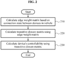
- FIG. 2 is a flowchart illustrating a method of calculating a device's controllability of a functional element in a vehicle according to an embodiment.
- a method of calculating a device's controllability of a functional element in a vehicle may include operation 210 of calculating an edge weight matrix based on a connection state between devices in a vehicle, operation 220 of calculating a transitive closure matrix using the edge weight matrix and operation 230 of calculating a device's controllability using the transitive closure matrix.
- ECUs electronice control units
- sensors various sensors, and actuators included in a vehicle
- Such an organic connection relationship of a plurality of devices may enable implementation of a user-centered interface with respect to the vehicle.
- risk of being an attack path of an outside intruder The intruder may indirectly attack an existing well-secured device through a vulnerability of another device.
- a vehicle security network design device may generate a risk analysis model in view of a controllability and a connection between functional elements corresponding to independent devices on the network in the vehicle.
- the vehicle security network design device may generate a graph model based on a connection structure between a plurality of functional elements in a vehicle.
- a functional element may denote a minimal unit of each of a plurality of functions associated with the vehicle and a functional unit to be performed by a single electronic component.
- the vertex may be defined as v i ⁇ V(0 ⁇ i ⁇ k) which is defined as each functional element in a case in which k functional elements exist in the vehicle.
- the edge may indicate the connection relationship between the plurality of functional elements and whether data is transmitted and received therebetween and be defined as (v i , v j ) ⁇ E(i ⁇ j, 0 ⁇ i, j ⁇ k).
- the vehicle security network design device may generate a graph model including any one of a one-way edge and a two-way edge based on a data transmission and reception direction between two functional elements connected to each other.
- the vehicle security network design device may implement a one-way uploading system to prevent a change in a directivity of data transmission and reception between functional elements in response to a security threat such as hacking and physically fix a communication direction between two devices to a predetermined direction.
- the one-way uploading system may be a physical and/or software function installed at a gateway which performs routing such that the functional elements are connected on a network. For example, if it has a one-way connection edge through which data is transmitted to a vertex vi and a vertex vj, and vj is unable to transmit data to vi, the one-way uploading system may be a means to non-reciprocally maintain this directivity.
- the one-way uploading system may guarantee a security class evaluated with respect to the functional elements and a validity of a management model therefor. Thus, while the security class is set and managed according to embodiments, the security attacker may not access or change the one-way uploading system.
- the one-way uploading system may be a means physically disposed between the vertex vi and the vertex vj to prevent a change of the data transmission direction.
- the one-way uploading system as a network element may maintain an edge direction in the original connection topology, thereby guaranteeing an evaluation, setting and a management validity of the security class.
- the one-way uploading system may be implemented by other applications applicable to the field of network and communications, and a structure and an operation of the one-way uploading system that may be deduced by a person skilled in the art although not described in detail should be construed as being employed for embodiments.
- the vehicle security network design device may calculate an edge weight matrix W based on a difference in the ASIL class and a connection structure between the plurality of functional elements using the generated directed graph model.
- the vehicle security network design device may use an undirected graph model.
- the vehicle security network design device may generate a more accurate risk analysis model using the directed graph model reflecting such data flow.
- the vehicle security network design device may calculate the edge weight matrix W using the following Equation 3 and Equation 4.
- a calculator in the vehicle security network design device may define a representative value A(v i ) based on the ASIL class corresponding to each of the functional elements.
- the representative value A(v i ) may be "0" if the ASIL class of the vertex vi corresponding to the functional element is QM and be defined to return values of "1" through "4", respectively, if the ASIL class is ASIL A through ASIL D.
- w i,j (0 ⁇ i,j ⁇ k) denotes a difference between A(v i ) and A(v j ) with respect to the edge (v i ,v j ) and may be defined as expressed by Equation 4.
- the vehicle security network design device may generate a weighted, directed graph in which a difference in the representative value A(v i ) corresponding to each edge is represented on a path of the edge.
- the generated weighted, directed graph will be described further with reference to the following drawings.
- the vehicle security network design device may generate a transitive closure matrix using the edge weight matrix calculated in operation 210.
- the calculator in the vehicle security network design device may calculate the transitive closure matrix indicating a total sum of weights of all edges included in a path between two random vertices.
- the calculator may calculate the transitive closure matrix T as expressed by the following Equation 5 and Equation 6.
- An element t i,j (0 ⁇ i,j ⁇ k) of the transitive closure matrix T calculated by the vehicle security network design device may indicate a total sum of weights of all edges on a path between the two vertices v i and v j .
- the element t i,j may be defined as expressed by Equation 6.
- vertices v x through v y may denote all vertices existing on a path between the two vertices v i and v j . If a value of the element t i,j is nil, it may indicate that there exists no path between the two vertices v i and v j .
- the value of the element t i,j may indicate that there exists at least one path between the two vertices v i and v j .
- the value of the element t i,j may be the same as a difference between A(v i ) and A(v j ), and thus in a case in which there exist at least two paths, a sum of weights of all edges on each path may be the same.
- the vehicle security network design device may calculate a device's controllability corresponding to each of the plurality of functional elements using the transitive closure matrix.
- the calculator in the vehicle security network design device may calculate a maximum value among values of a first row of the transitive closure matrix corresponding to a first vertex as a device's controllability of a functional element corresponding to the first vertex.
- the calculator may represent a greatest difference in the ASIL class between two vertices among vertices v j (0 ⁇ j ⁇ k) which the first vertex is reachable and which have a path connected from the first vertex.
- the vehicle security network design device since a negative number in the device's controllability is meaningless, the vehicle security network design device may regard the device's controllability for a negative number as "0".
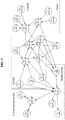
- FIG. 3 illustrates an example of a graph model of functional elements in a vehicle, the graph model generated by a vehicle security network design device according to an embodiment.
- a graph model representing 23 functional elements v 0 through v 22 included in a vehicle and a connection relationship therebetween as directed edges.
- the respective functional elements may be grouped into different functional regions in the vehicle.
- the first vertex v 0 through the third vertex v 2 may be included in a communication unit.
- the fourth vertex v 3 through the seventh vertex v 6 may be included in an infotainment.
- the eighth vertex v 7 through the fifteenth vertex v 14 may be included in an advanced driver-assistance system (ADAS).
- ADAS advanced driver-assistance system
- the seventeenth vertex v 16 through the twentieth vertex v 19 may be included in an engine.
- the twenty-first vertex v 20 through the twenty-third vertex v 22 may be included in a brake.
- An ASIL class indicated in each vertex may represent an ASIL class assigned by a level assigner in a vehicle security network design device, as described with reference to FIG. 1 .
- each ASIL class may be evaluated based on the ISO 26262 standard.
- FIG. 4 illustrates an example of a weighted, directed graph generated using a generated edge weight matrix according to an embodiment.
- a weighted, directed graph generated with respect to the plurality of functional elements in the vehicle of FIG. 3 is illustrated.
- a vehicle security network design device may generate an edge weight matrix W indicating a difference in an ASIL class between two functional elements included in each edge according to Equation 3 and Equation 4.
- the edge weight matrix W related to the plurality of functional elements in the vehicle in the example of FIG. 3 may be calculated as shown in the following Table 10.
- Table 10 i j 0 1 2 3 4 5 6 7 8 9 10 11 12 13 14 15 16 17 18 19 20 21 22 0 0 1 0 1 0 2 -1 3 4 5 0 -1 -2 -2 6 2 7 1 3 8 2 4 9 0 2 10 -1 0 0 11 1 1 12 -3 1 1 13 1 1 14 -4 0 15 1 2 2 16 2 17 -4 18 3 19 2 20 -4 0 21 2 22 3
- ASIL classes of the tenth vertex v 9 and the eleventh vertex v 10 may be assigned as ASIL B and ASIL D, respectively.
- A(v i ) corresponding to an ASIL class A(vg) may be determined to be "2"
- A(v 10 ) may be determined to be "4".
- the vehicle security network design device may calculate a value of each element of the edge weight matrix W.
- a value of nil is a non-existent value and thus, is not represented in Table 10.
- the weighted, directed graph of FIG. 4 may include 23 vertices. Further, the weighted, directed graph may further include edges representing data transmission and reception relationships of functional elements respectively corresponding to the 23 vertices. The edges may each include any one of a one-way edge and a two-way edge. In addition, the weighted, directed graph may represent a difference between representative values A(v i ) corresponding to ASIL classes of two vertices connected along the edge on a path of the edge.
- FIG. 5 illustrates an example of a directed graph reflecting a device's controllability according to an embodiment.
- a vehicle security network design device may calculate a transitive closure matrix T using the weighted, directed graph described with reference to FIG. 4 .
- a first path p 1 may be a path passing through the vertices v 9 , v 10 and v 13 .
- a second path p 2 may be a path passing through the vertices v 9 , v 12 and v 13 .
- the element t i,j may be consequentially calculated by A(v j )- A(v i ), and thus a resulting value may be the same.
- the transitive closure matrix T calculated using the weighted, directed graph described with reference to FIG. 4 may be calculated as shown in the following Table 11.
- the vehicle security network design device may calculate a device's controllability (DC) with respect to each of the functional elements using the transitive closure matrix calculated as shown in Table 11.
- the vehicle security network design device may define a device's controllability of a vertex v i as DC i .
- the vehicle security network design device may calculate a greatest value among data values of a tenth row as the device's controllability of the tenth vertex v 9 .
- t 9,j written in the tenth row of the transitive closure matrix of Table 11 are 0, 0, 1, -1, -2, ..., 2, and the vehicle security network design device may assign "2" which is the greatest value thereamong as DC 9 .
- the above description about the classes of the device's controllability are provided as an example only for better understanding of the disclosure and thus, should not construed as limiting or restricting the scope of other embodiments.
- FIG. 5 illustrates the graph model reflecting device's controllabilities of all functional elements in the vehicle which are calculated by the vehicle security network design device.
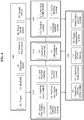
- FIG. 6 illustrates an example of a connection relationship of functional elements included in a vehicle according to an embodiment.
- a vehicle security network design device may receive data information exchanged between modules included in a predesigned vehicle as shown in the following Table 12.
- Table 12 Domain No Functional element ASIL class Data reception (Receiving From) Data transmission (Sending To) ADAS (620) a 0 Adaptive cruise control D s0. steer wheel angle p0. Throttle command s1. wheel speed of each wheel b1. Brake pressure command s3.
- Front vehicle tracking info s5. Front vehicle track info, Lane info h0. Set speed, headway gap info a 1 Lane departure D s0. steer wheel angle h0. Warning warning system s1. Wheel speed of each wheel S6.
- Lane info a 2 Lane keeping (assist) system D s0. steer wheel angle b1. braking pressure s1. wheel speed of each wheel e0. steering torque s5.
- Lane info a 5 Auto parking system D s0. steer wheel angle p0. throttle command s1. wheel speed of each wheel p1. gear engage command(P/R/D ) s4. surrounding vehicle info b1. brake pressure command s6. yaw rate b0. parking brake enable t0. target steering wheel angle h0. current parking space info Chassis (640) C 0 Traction control c s0. Steering wheel angle p0. throttle command s1. Wheel speed p1. transmissioin command(clutch (dis)engage) s6. Longitudinal acceleration b1. target brake pressure h0. intervention info c 1 Anti-lock braking system D s1. wheel speed info b1.
- traction control c 1. anti-lock braking system c 3. electronic stability system HMI (630) h 0 Dashboard, cluster unit A (Described in ADAS and chassis modules) - h 1 Infotainment system B - (Described in ADAS module) Power train (650) p 0 Engine management system D (Described in ADAS and chassis modules) - p 1 Transmission control system D (Described in ADAS and chassis modules) - Sensor (610) s 0 Steering wheel sensor C - (Described in ADAS and chassis modules) s 1 Wheel speed sensor C - (Described in ADAS and chassis modules) s 2 Tire pressure sensor A - (Described in ADAS and chassis modules) s 3 RADAR D - (Described in ADAS and chassis modules) s 4 Ultrasonic sensor A - (Described in ADAS and chassis modules) s 5 Vision (camera and tracking module) D - (Described in ADAS and chassis modules) s 6 Inertial sensor(Accele
- FIG. 6 a schematic example of wired and wireless networking in the vehicle defined as shown in Table 12 is illustrated.
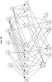
- FIG. 7A illustrates a directed graph model generated by a vehicle security network design device according to an embodiment.
- a directed graph model which represents ASIL classes and a connection relationship between a plurality of functional elements in wired and wireless networks in the vehicle defined as shown in Table 12 and FIG. 6 is illustrated.
- FIG. 7B illustrates a graph model reflecting a device's controllability from the directed graph model generated in FIG. 7A .
- a vehicle security network design device may calculate an edge weight matrix W and a transitive closure matrix T from the directed graph model described with reference to FIG. 7A . Further, the vehicle security network design device may calculate a device's controllability DC i corresponding to each of functional elements using the transitive closure matrix T. The description provided above may apply to the process of calculating the device's controllability, and thus duplicate description will be omitted.
- device's controllabilities DC i with respect to remaining functional elements may be calculated to be "0".
- a modeling algorithm related to a risk analysis model described in this example may be used to evaluate device's controllabilities of ECUs in the vehicle and to selectively detect a device to be affected when a security threat to a predetermined device occurs on a network. For example, in a case in which a security threat occurs at a predetermined node s 2 , s 3 , the vehicle security network design device may select a functional element having a higher ASIL class among functional elements existing in a range reachable from the corresponding node and display the corresponding functional element emphatically on a display of a user. In a case of a system with a huge IVN, it may not be easy to analyze functional elements with security vulnerability manually one by one. The vehicle security network design device may inspect the functional elements with security vulnerability in advance using a simulator to which the modeling algorithm related to the risk analysis model is applied, thereby increasing the safety.
- the vehicle security network design device may calculate a likelihood of risk occurrence with respect to each of the plurality of functional elements in the vehicle, an ASIL which provides a risk management standard with respect to each of the plurality of functional elements and a device's controllability with respect to each of the plurality of functional elements. Further, a manager in the vehicle security network design device may generate a risk analysis model of the plurality of functional elements based on the likelihood, the ASIL and the device's controllability. For example, with respect to the IVN suggested as shown in Table 12, the vehicle security network design device may generate a risk analysis model as shown in the following Table 13.
- ASIL class Device's controllability Risk occurrence likelihood D1 D2 D3 D4 QM DC0 QM QM QM QM DC1 QM QM QM S-ASIL A DC2 QM QM S-ASIL A S-ASIL B DC3 QM S-ASIL A S-ASIL B S-ASIL C DC4 S-ASIL A S-ASIL B S-ASIL C S-ASIL D ASIL A DC0 QM QM QM S-ASIL A DC1 QM QM S-ASIL A S-ASIL B DC2 QM S-ASIL A S-ASIL B S-ASIL C DC3 S-ASIL A ASIL B S-ASIL C S-ASIL D ASIL B DC0 QM QM S-ASIL A S-ASIL B DC1 QM S-ASIL A S-ASIL B S-ASIL C DC2 S-ASIL A S-ASIL B S-ASIL C S-ASIL D ASIL C DC0 QM S-ASIL A S-ASIL B
- QM may indicate a basic quality without a special requirement.
- S-ASIL A In a direction from S-ASIL A to S-ASIL D, a standard required for security threat related risk management with respect to a class may become higher.
- a secure-ASIL may be a risk analysis class assigned by the vehicle security network design device and indicate a risk analysis class of each of the plurality of functional elements calculated based on the likelihood, the ASIL and the device's controllability. According to the present embodiment, an effect of increasing the safety of security may be expected in that functional elements vulnerable to security threats may be evaluated based on a device's controllability even with respect to a networking system in a complex vehicle.
- the embodiments described herein may be implemented using hardware components, software components, and/or a combination thereof.
- the processing device and the component described herein may be implemented using one or more general-purpose or special purpose computers, such as, for example, a processor, a controller and an arithmetic logic unit (ALU), a digital signal processor, a microcomputer, a field programmable gate array (FPGA), a programmable logic unit (PLU), a microprocessor, or any other device capable of responding to and executing instructions in a defined manner.
- the processing device may run an operating system (OS) and one or more software applications that run on the OS.
- the processing device also may access, store, manipulate, process, and create data in response to execution of the software.
- OS operating system
- the processing device also may access, store, manipulate, process, and create data in response to execution of the software.
- a processing device may include multiple processing elements and/or multiple types of processing elements.
- a processing device may include multiple processors or a processor and a controller.
- different processing configurations are possible, such as parallel processors.
- the software may include a computer program, a piece of code, an instruction, or some combination thereof, to independently or collectively instruct and/or configure the processing device to operate as desired, thereby transforming the processing device into a special purpose processor.
- Software and data may be embodied permanently or temporarily in any type of machine, component, physical or virtual equipment, computer storage medium or device, or in a propagated signal wave capable of providing instructions or data to or being interpreted by the processing device.
- the software also may be distributed over network coupled computer systems so that the software is stored and executed in a distributed fashion.
- the software and data may be stored by one or more non-transitory computer readable recording mediums.
- the methods according to the above-described example embodiments may be recorded in non-transitory computer-readable media including program instructions to implement various operations of the above-described example embodiments.
- the media may also include, alone or in combination with the program instructions, data files, data structures, and the like.
- the program instructions recorded on the media may be those specially designed and constructed for the purposes of example embodiments, or they may be of the kind well-known and available to those having skill in the computer software arts.
- non-transitory computer-readable media examples include magnetic media such as hard disks, floppy disks, and magnetic tape; optical media such as CD-ROM discs, DVDs, and/or Blue-ray discs; magneto-optical media such as optical discs; and hardware devices that are specially configured to store and perform program instructions, such as read-only memory (ROM), random access memory (RAM), flash memory (e.g., USB flash drives, memory cards, memory sticks, etc.), and the like.
- program instructions include both machine code, such as produced by a compiler, and files containing higher level code that may be executed by the computer using an interpreter.
- the above-described devices may be configured to act as one or more software modules in order to perform the operations of the above-described example embodiments, or vice versa.
Landscapes
- Engineering & Computer Science (AREA)
- Physics & Mathematics (AREA)
- General Physics & Mathematics (AREA)
- Computer Security & Cryptography (AREA)
- General Engineering & Computer Science (AREA)
- Computer Hardware Design (AREA)
- Computing Systems (AREA)
- Computer Networks & Wireless Communication (AREA)
- Signal Processing (AREA)
- Business, Economics & Management (AREA)
- Emergency Management (AREA)
- Mechanical Engineering (AREA)
- Software Systems (AREA)
- Theoretical Computer Science (AREA)
- Small-Scale Networks (AREA)
- Traffic Control Systems (AREA)
Abstract
Description
- Embodiments of the present invention relate to a field of vehicle system security and, more particularly, to a method of evaluating and managing security classes with respect to functional elements included in a vehicle and a device performing the same.
- An initial automobile was an assembly of mechanical technologies. However, as gradually combined with electronic components, the automobile has enabled various functions and services such as automatic transmission, remote control and navigation and been developed to support high technology such as autonomous driving. Unlike components of general electronic products, malfunction of automobile electronic components may lead to serious accidents in some cases. With the increasing proportion of electronic components in a vehicle, the importance of "functional safety" has been emphasized. The "functional safety" refers to freedom from unreasonable risk, which means a rational risk level. The rational risk may indicate that a probability of malfunction occurrence is lowered and managed at a rational level based on classes of the electronic components.
- Automobile components such as electronic components have different severities with respect to malfunction, and thus the International Organization for Standardization (ISO) 26262 standard that determines a rational risk class for each component has been established and provided as a risk analysis method for functional safety and a response method. However, the number of electronic components in a vehicle has been increased these days, and the components in the vehicle are connected to each other or other vehicles on a network. Thus, a risk analysis method considering a risk element of intended malfunction by security threats as well as malfunction caused by fault is needed. Further, the International Electrotechnical Commission (IEC) 62443 which is the industrial security standard is capable of considering a realizability of security threats, but not a characteristic of a vehicle environment.
- According to an aspect of the present invention, there is provided a vehicle security network design device implemented by a processor. The vehicle security network design device may include a level assigner configured to assign an automobile safety integrity level (ASIL) which provides a risk management standard for each of a plurality of functional elements in a vehicle, a calculator configured to calculate a device's controllability with respect to each of the plurality of functional elements based on a difference in the ASIL and a connection structure between the plurality of functional elements, and a manager configured to establish and manage a risk analysis model of the plurality of functional elements based on the ASIL and the device's controllability.
- The calculator may be configured to generate a graph including a vertex corresponding to each of the plurality of functional elements and an edge indicating whether data is transmitted and received between the plurality of functional elements. In further detail, the calculator may be configured to generate the graph including any one of a one-way edge and a two-way edge based on a data transmission and reception direction between two functional elements connected to each other.
- The calculator may be configured to generate an edge weight matrix indicating a difference in the ASIL between two functional elements included in each edge. Further, the calculator may be configured to generate a weighted, directed graph in which the difference in the ASIL corresponding to the each edge is represented on a path of the edge.
- The calculator may be configured to generate a transitive closure matrix indicating a sum of weights of at least one edge included in a path between two random vertices. Further, the calculator may be configured to calculate a difference in the ASIL between a first vertex and a second vertex as a device's controllability of a functional element corresponding to the first vertex, the second vertex maximizing the difference in the ASIL among at least one vertex having a path connected from the first vertex.
- The calculator may be configured to calculate a maximum value among values of a first row of the transitive closure matrix corresponding to the first vertex as the device's controllability of the functional element corresponding to the first vertex.
- The level assigner may be configured to assign a likelihood of risk occurrence with respect to each of the plurality of functional elements in the vehicle, and the manager may be configured to generate the risk analysis model of the plurality of functional elements based on the likelihood, the ASIL and the device's controllability. The level assigner may be configured to assign the likelihood according to the International Electrotechnical Commission (IEC) 62443 based on a realizability and a security vulnerability of a threat to each of the plurality of functional elements, and assign the ASIL according to the International Organization for Standardization (ISO) 26262 based on an accidental severity, an accidental exposure probability and a controllability with respect to each of the plurality of functional elements.
- According to another aspect of the present invention, there is provided a method of calculating a device's controllability of a functional element in a vehicle, the method including calculating an edge weight matrix indicating a connection state of a plurality of functional elements in a vehicle based on a difference in ASIL and a connection structure between the plurality of functional elements, calculating a transitive closure matrix indicating a sum of weights of at least one edge included in a path between two random vertices using the edge weight matrix, and calculating a device's controllability of a functional element corresponding to a first vertex based on the ASIL of each of at least one vertex having a path connected from the first vertex.
- The calculating of the edge weight matrix may further include generating vertices corresponding to the plurality of functional elements, and generating a graph including an edge indicating whether data is transmitted and received between two random vertices.
- The generating of the graph including the edge may include generating the graph including any one of a one-way edge and a two-way edge based on a data transmission and reception direction between the two random vertices. Further, the generating of the graph including the edge may include generating a weighted, directed graph in which a difference in the ASIL between two vertices corresponding each edge is represented on a path of the each edge.
- The calculating of the device's controllability may include calculating a maximum value among values of a first row of the transitive closure matrix corresponding to the first vertex as the device's controllability of the functional element corresponding to the first vertex.
- The calculating of the device's controllability may include calculating a difference in the ASIL between the first vertex and a second vertex as the device's controllability of the functional element corresponding to the first vertex, the second vertex among at least one vertex having a path connected from the first vertex, and the second vertex may be a vertex which maximizes the difference in the ASIL from the first vertex.
- According to still another aspect of the present invention, there is provided a program stored in a computer-readable medium, the program including an instruction set to perform a vehicle security network design method. In further detail, the instruction set may include an instruction set configured to assign a likelihood of risk occurrence with respect to each of a plurality of functional elements in a vehicle, an instruction set configured to assign an ASIL related to a risk management standard with respect to each of the plurality of functional elements in the vehicle, an instruction set configured to calculate a device's controllability with respect to each of the plurality of functional elements based on a difference in the ASIL and a connection structure between the plurality of functional elements, and an instruction set configured to generate a risk analysis model of the plurality of functional elements based on the likelihood, the ASIL and the device's controllability.
-
-
FIG. 1 is a block diagram illustrating a vehicle security network design device according to an embodiment. -
FIG. 2 is a flowchart illustrating a method of calculating a device's controllability of a functional element in a vehicle according to an embodiment. -
FIG. 3 illustrates an example of a graph model of functional elements in a vehicle, the graph model generated by a vehicle security network design device according to an embodiment. -
FIG. 4 illustrates an example of a weighted, directed graph generated using a generated edge weight matrix according to an embodiment. -
FIG. 5 illustrates an example of a directed graph reflecting a device's controllability according to an embodiment. -
FIG. 6 illustrates an example of a connection relationship of functional elements included in a vehicle according to an embodiment. -
FIG. 7A illustrates a directed graph model generated by a vehicle security network design device according to an embodiment. -
FIG. 7B illustrates a graph model reflecting a device's controllability from the directed graph model generated inFIG. 7A . - The following detailed structural or functional description of embodiments is provided as an example only and various alterations and modifications may be made to the embodiments. Accordingly, the embodiments are not construed as being limited to the disclosure and should be understood to include all changes, equivalents, and replacements within the technical scope of the disclosure.
- Terms, such as first, second, and the like, may be used herein to describe components. Each of these terminologies is not used to define an essence, order or sequence of a corresponding component but used merely to distinguish the corresponding component from other component(s). For example, a first component may be referred to as a second component, and similarly the second component may also be referred to as the first component.
- It should be noted that if it is described that one component is "connected", "coupled", or "joined" to another component, a third component may be "connected", "coupled", and "joined" between the first and second components, although the first component may be directly connected, coupled, or joined to the second component.
- The singular forms "a", "an", and "the" are intended to include the plural forms as well, unless the context clearly indicates otherwise. It will be further understood that the terms "comprises/comprising" and/or "includes/including" when used herein, specify the presence of stated features, integers, steps, operations, elements, and/or components, but do not preclude the presence or addition of one or more other features, integers, steps, operations, elements, components and/or groups thereof.
- Unless otherwise defined, all terms, including technical and scientific terms, used herein have the same meaning as commonly understood by one of ordinary skill in the art to which this disclosure pertains. Terms, such as those defined in commonly used dictionaries, are to be interpreted as having a meaning that is consistent with their meaning in the context of the relevant art, and are not to be interpreted in an idealized or overly formal sense unless expressly so defined herein.
- Hereinafter, embodiments will be described in detail with reference to the accompanying drawings. The same component or components corresponding to each other will be provided with the same reference numeral, and their detailed explanation will be omitted.
-
FIG. 1 is a block diagram illustrating a vehicle security network design device according to an embodiment. A vehicle securitynetwork design device 100 may include a processor. Referring toFIG. 1 , the vehicle securitynetwork design device 110 may include alevel assigner 110, acalculator 120 and amanager 130 that are at least temporarily implemented by the processor. Thelevel assigner 110 may assign an automobile safety integrity level (ASIL) which provides a risk management standard with respect to each of a plurality of functional elements in a vehicle. In further detail, thelevel assigner 110 may assign an ASIL of each of the plurality of functional elements connected to a controller area network (CAN) of the vehicle based on thefollowing Equation 1. However, the CAN is merely an example of an intra-vehicle network (IVN) which is managed according to embodiments, and thus description provided using the example of the CAN should not be construed as limiting the scope of the present disclosure to a specific application.
- The
level assigner 110 may assign an ASIL level by combining an accidental severity level according to a hazard occurring by a fault or functional failure of a device, a probability of exposure level reflecting an operational situation of the vehicle, and a controllability of a driver since an accident may be prevented by a control of the driver although a mechanical malfunction occurs. As an example, the International Organization for Standardization (ISO) 26262 standard may be used for the ASIL level assignment of thelevel assigner 110. - The
level assigner 110 may determine an accidental severity level as follows to assign an ASIL class related to the risk management standard. An exemplary evaluation matrix is introduced as shown in the following Table 1.[Table 1] Description No injuries Light injuries Severe injuries (life-threatening) Severity level S S0 S1 S2 - In addition, the
level assigner 110 may determine a probability of exposure level related to a hazard element as follows. An exemplary evaluation matrix is introduced as shown in the following Table 2.[Table 2] Probability of exposure level E Probability Probability range (x) Frequency EO No E1 Very low Once a year E2 Low x<1% Several times a year E3 Medium 1%≤x<10% Once a month E4 High 10%≤x Often during driving - Further, the
level assigner 110 may determine a controllability level as follows, the controllability level indicating a probability of escaping from the hazard by a control of the driver in a situation in which an accident is likely to occur. An exemplary evaluation matrix is introduced as shown in the following Table 3.[Table 3] Description Controllable Simply controllable Normally controllable Situation Easy Avoid accident at probability of 99% or higher Avoid accident at probability of 90% or higher Controllability level C C0 C1 C2 - As shown above, the accidental severity level according to the hazard, the probability of exposure level reflecting the operational situation of the vehicle and the controllability of the driver are determined, and the
level assigner 110 may assign the ASIL class by combining the same. An exemplary matrix is introduced as shown in the following Table 4.[Table 4] Severity level S Probability of exposure level E Controllability level C C0 C1 C2 C3 S1 E1 QM QM QM QM E2 QM QM QM QM E3 QM QM QM ASIL A E4 QM QM ASIL A ASIL B S2 E1 QM QM QM QM E2 QM QM QM ASIL A E3 QM QM ASIL A ASIL B E4 QM ASIL A ASIL B ASIL C S3 E1 QM QM QM ASIL A E2 QM QM ASIL A ASIL B E3 QM ASIL A ASIL B ASIL C E4 ASIL A ASIL B ASIL C ASIL D - In Table 4, a quality management (QM) may indicate a basic quality without a special requirement. In a direction from ASIL A to ASIL D, a standard required for risk management with respect to a class may become higher. The above described evaluation levels may be represented as results ranked as shown in Table 4. However, in another example, it may also be represented as a risk level vector including each evaluation level as an element.
- Further, according to an embodiment, the
level assigner 110 may assign a likelihood of risk occurrence based on a predesignated standard with respect to each of the plurality of functional elements in the vehicle. In further detail, thelevel assigner 110 may assign the likelihood of risk occurrence based on the followingEquation 2.
- The
level assigner 110 may assign the likelihood of risk occurrence based on a combination of a security vulnerability (likelihood of exploited vulnerability) and a threat realizability (likelihood of realized threat) as expressed byEquation 2. In further detail, thelevel assigner 110 may evaluate the threat realizability level as a potential likelihood with respect to a security attack, and be determined, in detail, in view of human resources of an attacker, material resources, and a required time. For example, the threat realizability level is evaluated relatively high with respect to a low level of experience and related knowledge required for attack, a low level of equipment necessary for attack, and a less time taken for attack. Exemplary evaluation matrices are introduced in the following Table 5 and Table 6.[Table 5] Evaluation standard Content Class Description Required skill Ordinary person High Person with lack of or no related knowledge or experience Skilled person Medium Person having related knowledge or experience and capable of utilizing existing published attack method Security expert Low Person having knowledge and experience related to security attack and capable of proposing new attack method Attack resources General/no equipment High Immediately available general equipment Technical/purchased equipment Medium Purchasable without great effort Ordered/manufactured equipment Low Commonly unavailable or quite expensive, or need to be made to order Attack Immediate High System malfunctions soon when attack time starts Within driving time Medium System malfunctions by attack while vehicle is turned on Other long periods Low Case of long attack time to make vehicle system malfunction [Table 6] Threat realizability level T Skill Attack resource Attack time High Medium Low High High T3 T3 T 3 Medium T3 T3 T2 Low T3 T2 T1 Medium High T3 T3 T2 Medium T3 T2 T1 Low T2 T1 - Low High T3 T2 T1 Medium T2 T1 - Low T1 - - - Further, the
level assigner 110 may evaluate a security vulnerability exposure level based on an openness of a target system and evaluate the same based on how information of an attack target is published to an outside, how often the information is 5 used, and how to access the information. For example, the security vulnerability exposure level may be evaluated relatively high for a high frequency of use of the target system, a lot of information being published, and a great openness of the access level. Exemplary evaluation matrices are introduced in the following Table 7 and Table 8.[Table 7] Evaluation standard Content Class Description Frequency High High Every driving / Every moment of use Medium Medium Once or twice a month / Often Low Low Once or twice a year / Sometimes Information Publication Published High Published through Internet and provided manual Involved worker Medium Owned by service center, manufacturing company, parts manufacturing company, etc. Confidential document Low Available to authorized person at service center, manufacturing company or parts manufacturing company Access level Open High Accessible through Internet or by unauthorized person General user Medium Accessible by driver only Special user Low Accessible with authority of service center, manufacturing company or parts manufacturing company [Table 8] Security vulnerability exposure level Vulnerability Exploited (V) Frequency of use Information publication Access level High Medium Low High High V3 V3 V3 Medium V3 V3 V2 Low V3 V2 V1 Medium High V3 V3 V2 Medium V3 V2 V1 Low V2 V1 - Low High V3 V2 V1 Medium V2 V1 - Low V1 - - - The
level assigner 110 may assign the likelihood of risk occurrence based on a combination of the assigned threat realizability level and the assigned security vulnerability exposure level, as shown in the following Table 9.[Table 9] Risk occurrence likelihood level D Realizability of threat Security vulnerability exposure V3 V2 V1 T3 D4 D3 D2 T2 D3 D2 D1 T1 D2 D1 - - The
calculator 120 may calculate a device's controllability with respect to each of the plurality of functional elements based on a difference in the ASIL class and a connection structure between the plurality of functional elements in the vehicle. The calculated device's controllability is a different concept from a controllability of a user which is defined in the ISO 26262 standard and is a factor which is newly defined here to consider a controllability and a connection between functional elements on a network in the vehicle. - The
calculator 120 may generate a graph including a vertex corresponding to each of the plurality of functional elements and an edge indicating whether data is transmitted and received between the plurality of functional elements. Here, the edge may be one of a one-way edge and a two-way edge based on a data transmission and reception direction between two functional elements (vertices) connected to each other. Thecalculator 120 may generate an edge weight matrix indicating a difference in the ASIL between two functional elements included in each edge. Thecalculator 120 may calculate a transitive closure matrix indicating a sum of weights of at least one edge included in a path between two random vertices. For each vertex, thecalculator 120 may detect a class difference from vj having a greatest difference in the ASIL class from vi, with respect to the vertex vj (0 ≤ j < k) which may receive data from the vertex vi, that is, which the vertex vi is reachable. This may be calculated by finding and taking a greatest value among all values of an (i+1)-th row in the transitive closure matrix T. Thecalculator 120 may deduce this as a device's controllability (DC) with respect to the vertex. Detailed examples will be described with reference to the following drawings. - The
manager 130 may newly generate and manage a risk analysis model of the plurality of functional elements based on the ASIL, the likelihood and the device's controllability. The ASIL may denote a class calculated based on the ISO 26262 standard. Accordingly, the ASIL may consider factors such as an operational situation of the vehicle and a controllability of the driver which have effects when a potential threat leads to an accident. - However, the ISO 26262 standard assumes that a fault or error and a functional failure which cause occurrence of threats occurs stochastically. However, a security threat may be intentionally made by an attacker having intelligence, unlike a simple mechanical fault. Thus, the likelihood of risk occurrence may consider factors such as a likelihood with respect to the security threat like the IEC 62443. The vehicle security network design device may cover risk analysis factors that the two standards, the ISO 26262 and the IEC 62443, consider, thereby supplementing an accuracy of risk analysis related to each of the functional elements. The
manager 130 may manage a vehicle security management class that is newly analyzed in this way as a security-ASIL (S-ASIL). Detailed description will be provided later using examples with reference toFIG. 7 and the like. In the description set forth hereinafter, a method of calculating the device's controllability with respect to each of the plurality of functional elements will be described in detail. -
FIG. 2 is a flowchart illustrating a method of calculating a device's controllability of a functional element in a vehicle according to an embodiment. Referring toFIG. 2 , a method of calculating a device's controllability of a functional element in a vehicle may includeoperation 210 of calculating an edge weight matrix based on a connection state between devices in a vehicle,operation 220 of calculating a transitive closure matrix using the edge weight matrix andoperation 230 of calculating a device's controllability using the transitive closure matrix. - Today, electronic control units (ECUs), various sensors, and actuators included in a vehicle may be connected on a network and exchange a variety of data with each other. Such an organic connection relationship of a plurality of devices may enable implementation of a user-centered interface with respect to the vehicle. However, there may also exist a risk of being an attack path of an outside intruder. The intruder may indirectly attack an existing well-secured device through a vulnerability of another device. To consider the likelihood as described above as well, a vehicle security network design device may generate a risk analysis model in view of a controllability and a connection between functional elements corresponding to independent devices on the network in the vehicle.
- In
operation 210, the vehicle security network design device may generate a graph model based on a connection structure between a plurality of functional elements in a vehicle. In the following description, a functional element may denote a minimal unit of each of a plurality of functions associated with the vehicle and a functional unit to be performed by a single electronic component. The vehicle security network design device may generate a graph model G=(V, E) including a vertex corresponding to each of the plurality of functional elements and an edge indicating a connection relationship between the plurality of functional elements. - For example, the vertex may be defined as vi∈V(0≤i<k) which is defined as each functional element in a case in which k functional elements exist in the vehicle. In addition, the edge may indicate the connection relationship between the plurality of functional elements and whether data is transmitted and received therebetween and be defined as (vi, vj)∈E(i≠j, 0≤i, j<k). In further detail, the vehicle security network design device may generate a graph model including any one of a one-way edge and a two-way edge based on a data transmission and reception direction between two functional elements connected to each other.
- In another example, the vehicle security network design device may implement a one-way uploading system to prevent a change in a directivity of data transmission and reception between functional elements in response to a security threat such as hacking and physically fix a communication direction between two devices to a predetermined direction.
- The one-way uploading system may be a physical and/or software function installed at a gateway which performs routing such that the functional elements are connected on a network. For example, if it has a one-way connection edge through which data is transmitted to a vertex vi and a vertex vj, and vj is unable to transmit data to vi, the one-way uploading system may be a means to non-reciprocally maintain this directivity. The one-way uploading system may guarantee a security class evaluated with respect to the functional elements and a validity of a management model therefor. Thus, while the security class is set and managed according to embodiments, the security attacker may not access or change the one-way uploading system.
- Meanwhile, in another example, the one-way uploading system may be a means physically disposed between the vertex vi and the vertex vj to prevent a change of the data transmission direction. The one-way uploading system as a network element may maintain an edge direction in the original connection topology, thereby guaranteeing an evaluation, setting and a management validity of the security class.
- In addition, the one-way uploading system may be implemented by other applications applicable to the field of network and communications, and a structure and an operation of the one-way uploading system that may be deduced by a person skilled in the art although not described in detail should be construed as being employed for embodiments.
- Further, in
operation 210, the vehicle security network design device may calculate an edge weight matrix W based on a difference in the ASIL class and a connection structure between the plurality of functional elements using the generated directed graph model. In a case of using a configuration in which the plurality of functional elements existing on the network in the vehicle is connected through the ECUs, the vehicle security network design device may use an undirected graph model. However, in an actual vehicle, rather than a simple connection relationship like data transmission and reception from a sensor to a controller or data transmission and reception from the controller to an actuator, a direction in which data is transmitted and received may exist. The vehicle security network design device may generate a more accurate risk analysis model using the directed graph model reflecting such data flow. - In further detail, the vehicle security network design device may calculate the edge weight matrix W using the following
Equation 3 andEquation 4.

- A calculator in the vehicle security network design device may define a representative value A(vi) based on the ASIL class corresponding to each of the functional elements. For example, but not limited thereto, the representative value A(vi) may be "0" if the ASIL class of the vertex vi corresponding to the functional element is QM and be defined to return values of "1" through "4", respectively, if the ASIL class is ASIL A through ASIL D. Further, wi,j (0≤i,j<k) denotes a difference between A(vi) and A(vj) with respect to the edge (vi,vj) and may be defined as expressed by
Equation 4. - Further, the vehicle security network design device may generate a weighted, directed graph in which a difference in the representative value A(vi) corresponding to each edge is represented on a path of the edge. The generated weighted, directed graph will be described further with reference to the following drawings.
- In
operation 220, the vehicle security network design device may generate a transitive closure matrix using the edge weight matrix calculated inoperation 210. In further detail, the calculator in the vehicle security network design device may calculate the transitive closure matrix indicating a total sum of weights of all edges included in a path between two random vertices. For example, the calculator may calculate the transitive closure matrix T as expressed by the followingEquation 5 and Equation 6.

- An element ti,j(0≤i,j<k) of the transitive closure matrix T calculated by the vehicle security network design device may indicate a total sum of weights of all edges on a path between the two vertices vi and vj. In further detail, the element ti,j may be defined as expressed by Equation 6. In Equation 6, vertices vx through vy may denote all vertices existing on a path between the two vertices vi and vj. If a value of the element ti,j is nil, it may indicate that there exists no path between the two vertices vi and vj. Otherwise, if the value of the element ti,j is present, it may indicate that there exists at least one path between the two vertices vi and vj. As a result, the value of the element ti,j may be the same as a difference between A(vi) and A(vj), and thus in a case in which there exist at least two paths, a sum of weights of all edges on each path may be the same.
- In
operation 230, the vehicle security network design device may calculate a device's controllability corresponding to each of the plurality of functional elements using the transitive closure matrix. In further detail, the calculator in the vehicle security network design device may calculate a maximum value among values of a first row of the transitive closure matrix corresponding to a first vertex as a device's controllability of a functional element corresponding to the first vertex. Further, the calculator may represent a greatest difference in the ASIL class between two vertices among vertices vj(0≤j<k) which the first vertex is reachable and which have a path connected from the first vertex. In addition, since a negative number in the device's controllability is meaningless, the vehicle security network design device may regard the device's controllability for a negative number as "0". - The above description has provided a modeling algorithm and a graph model used by the vehicle security network design device to generate a list analysis model. Hereinafter, an exemplary process of generating a risk analysis model in an in-vehicle networking (IVN) environment in a vehicle will be described in further detail.
-
FIG. 3 illustrates an example of a graph model of functional elements in a vehicle, the graph model generated by a vehicle security network design device according to an embodiment. Referring toFIG. 3 , an example of a graph model representing 23 functional elements v0 through v22 included in a vehicle and a connection relationship therebetween as directed edges. For example, the respective functional elements may be grouped into different functional regions in the vehicle. In an example, the first vertex v0 through the third vertex v2 may be included in a communication unit. In another example, the fourth vertex v3 through the seventh vertex v6 may be included in an infotainment. Similarly, the eighth vertex v7 through the fifteenth vertex v14 may be included in an advanced driver-assistance system (ADAS). Further, the seventeenth vertex v16 through the twentieth vertex v19 may be included in an engine. In addition, the twenty-first vertex v20 through the twenty-third vertex v22 may be included in a brake. - An ASIL class indicated in each vertex may represent an ASIL class assigned by a level assigner in a vehicle security network design device, as described with reference to
FIG. 1 . For example, but not limited thereto, each ASIL class may be evaluated based on the ISO 26262 standard. -
FIG. 4 illustrates an example of a weighted, directed graph generated using a generated edge weight matrix according to an embodiment. Referring toFIG. 4 , a weighted, directed graph generated with respect to the plurality of functional elements in the vehicle ofFIG. 3 is illustrated. A vehicle security network design device may generate an edge weight matrix W indicating a difference in an ASIL class between two functional elements included in each edge according toEquation 3 andEquation 4. - The edge weight matrix W related to the plurality of functional elements in the vehicle in the example of
FIG. 3 may be calculated as shown in the following Table 10.[Table 10] i j 0 1 2 3 4 5 6 7 8 9 10 11 12 13 14 15 16 17 18 19 20 21 22 0 0 1 0 1 0 2 -1 3 4 5 0 -1 -2 -2 6 2 7 1 3 8 2 4 9 0 2 10 -1 0 0 11 1 1 12 -3 1 1 13 1 1 14 -4 0 15 1 2 2 16 2 17 -4 18 3 19 2 20 -4 0 21 2 22 3 - For example, ASIL classes of the tenth vertex v9 and the eleventh vertex v10 may be assigned as ASIL B and ASIL D, respectively. In this example, with respect to a representative value A(vi) corresponding to an ASIL class, A(vg) may be determined to be "2", and A(v10) may be determined to be "4". Accordingly, the vehicle security network design device may calculate an element w9,10=A(v10)- A(v9) of the edge weight matrix W to be "2". Similarly, the vehicle security network design device may calculate a value of each element of the edge weight matrix W. A value of nil is a non-existent value and thus, is not represented in Table 10.
- The weighted, directed graph of
FIG. 4 may include 23 vertices. Further, the weighted, directed graph may further include edges representing data transmission and reception relationships of functional elements respectively corresponding to the 23 vertices. The edges may each include any one of a one-way edge and a two-way edge. In addition, the weighted, directed graph may represent a difference between representative values A(vi) corresponding to ASIL classes of two vertices connected along the edge on a path of the edge. -
FIG. 5 illustrates an example of a directed graph reflecting a device's controllability according to an embodiment. According toEquation 5 and Equation 6, a vehicle security network design device may calculate a transitive closure matrix T using the weighted, directed graph described with reference toFIG. 4 . For example, referring to the graph ofFIG. 4 , there may exist two shortest paths connected from the tenth vertex v9 to the fourth vertex v13. In further detail, a first path p1 may be a path passing through the vertices v9, v10 and v13. In addition, a second path p2 may be a path passing through the vertices v9, v12 and v13. - Accordingly, a calculator in the vehicle security network design device may calculate an element t9,13=w9,10 +w10,13= w9,12 +w12,13 of the transitive closure matrix T to be "2". As described above, irrespective of a path, the element ti,j may be consequentially calculated by A(vj)- A(vi), and thus a resulting value may be the same. For example, the transitive closure matrix T calculated using the weighted, directed graph described with reference to
FIG. 4 may be calculated as shown in the following Table 11.[Table 11] i j 0 1 2 3 4 5 6 7 8 9 10 11 12 13 14 15 16 17 18 19 20 21 22 0 0 1 -1 -2 0 -2 1 0 1 -1 -2 0 -2 2 -1 -1 -2 -3 -1 -3 3 4 5 0 0 1 -1 -2 -2 6 2 2 3 1 0 2 7 1 1 2 0 -1 1 -1 3 2 3 3 3 3 8 2 2 3 1 0 2 0 4 3 4 4 4 4 9 0 0 1 -1 -2 0 -2 2 1 2 2 2 2 10 -2 -2 -1 -3 -4 -2 -4 -1 0 0 0 0 11 -1 -1 0 -2 -3 -1 -3 1 0 1 1 1 1 12 -1 -1 0 -2 -3 -1 -3 1 1 1 1 13 -2 -2 -1 -3 -4 -2 -4 0 0 14 -2 -2 -1 -3 -4 -2 -4 0 0 0 15 0 0 1 -1 -2 0 -2 1 2 2 2 2 16 0 0 1 -1 -2 0 -2 2 17 -2 -2 -1 -3 -4 -2 -4 18 1 1 2 0 -1 0 -1 3 19 0 0 1 -1 -2 0 -2 2 20 -2 -2 -1 -3 -4 -2 -4 0 21 0 0 1 -1 -2 0 -2 2 2 22 1 1 2 0 -1 0 -1 3 3 - Further, the vehicle security network design device may calculate a device's controllability (DC) with respect to each of the functional elements using the transitive closure matrix calculated as shown in Table 11. The vehicle security network design device may define a device's controllability of a vertex vi as DCi. For example, in a case of calculating a device's controllability of a tenth vertex v9, the vehicle security network design device may calculate a greatest value among data values of a tenth row as the device's controllability of the tenth vertex v9. In further detail, t9,j written in the tenth row of the transitive closure matrix of Table 11 are 0, 0, 1, -1, -2, ..., 2, and the vehicle security network design device may assign "2" which is the greatest value thereamong as DC9. In this example, the device's controllability may be defined as 5 classes from DCi=0 having a least difference in the ASIL class to DCi=4 having a greatest difference in the ASIL class. However, the above description about the classes of the device's controllability are provided as an example only for better understanding of the disclosure and thus, should not construed as limiting or restricting the scope of other embodiments. For example, it is obvious to a person skilled in the art that more elaborate device's controllability classes or more convenient device's controllability classes may be assigned depending on a need of a designer.
FIG. 5 illustrates the graph model reflecting device's controllabilities of all functional elements in the vehicle which are calculated by the vehicle security network design device. -
FIG. 6 illustrates an example of a connection relationship of functional elements included in a vehicle according to an embodiment. A vehicle security network design device may receive data information exchanged between modules included in a predesigned vehicle as shown in the following Table 12.[Table 12] Domain No Functional element ASIL class Data reception (Receiving From) Data transmission (Sending To) ADAS (620) a0 Adaptive cruise control D s0. steer wheel angle p0. Throttle command s1. wheel speed of each wheel b1. Brake pressure command s3. Front vehicle tracking info s5. Front vehicle track info, Lane info h0. Set speed, headway gap info a1 Lane departure D s0. steer wheel angle h0. Warning warning system s1. Wheel speed of each wheel S6. Lane info a2 Lane keeping (assist) system D s0. steer wheel angle b1. braking pressure s1. wheel speed of each wheel e0. steering torque s5. Lane info s6. yaw rate, lateral acceleration h0. Warning a3 Highway drive assist system D s0. steer wheel angle b1. braking pressure s1. wheel speed of each wheel s3. front vehicle tracking info p0. throttle command s5. front vehicle track info, Lane info e0. steering torque/target angle s6. Lateral acceleration, yaw rate h0. current set speed, warning h1. road condition a4 Active front lighting system B s0. steer wheel angle h0. high beam info s1. wheel speed of each wheel s3. front vehicle tracking info s5. front vehicle track info, Lane info a5 Auto parking system D s0. steer wheel angle p0. throttle command s1. wheel speed of each wheel p1. gear engage command(P/R/D ) s4. surrounding vehicle info b1. brake pressure command s6. yaw rate b0. parking brake enable t0. target steering wheel angle h0. current parking space info Chassis (640) C0 Traction control c s0. Steering wheel angle p0. throttle command s1. Wheel speed p1. transmissioin command(clutch (dis)engage) s6. Longitudinal acceleration b1. target brake pressure h0. intervention info c1 Anti-lock braking system D s1. wheel speed info b1. Target brake pressure p1. transmission command(clutch control) h0. intervention info c2 Active damping system c s0. steering wheel angle (Embedded actuator) Target damping coefficient s1. wheel speed info. s6. yaw rate, lateral acceleration, longitudinal acceleration c3 Electronic stability system D s0. steering wheel angle b1. target brake pressure s1. wheel speed info. s6. yaw rate, lateral acceleration h0. intervention info Brake (650) b0 Electronic parking brake system B a5. auto parking system h0. parking brake status b1 Electronic Brake control D a0. adaptive cruise control - a2. lane keeping (assist) system a3. highway drive assist system a5. auto parking system c0. traction control c1. anti-lock braking system c3. electronic stability system HMI (630) h0 Dashboard, cluster unit A (Described in ADAS and chassis modules) - h1 Infotainment system B - (Described in ADAS module) Power train (650) p0 Engine management system D (Described in ADAS and chassis modules) - p1 Transmission control system D (Described in ADAS and chassis modules) - Sensor (610) s0 Steering wheel sensor C - (Described in ADAS and chassis modules) s1 Wheel speed sensor C - (Described in ADAS and chassis modules) s2 Tire pressure sensor A - (Described in ADAS and chassis modules) s3 RADAR D - (Described in ADAS and chassis modules) s4 Ultrasonic sensor A - (Described in ADAS and chassis modules) s5 Vision (camera and tracking module) D - (Described in ADAS and chassis modules) s6 Inertial sensor(Accelerat C - (Described in ADAS and ion, yaw rate) chassis modules) Steer (650) t0 Electronic power steering D (Described in ADAS and chassis modules) - - Referring to
FIG. 6 , a schematic example of wired and wireless networking in the vehicle defined as shown in Table 12 is illustrated. -
FIG. 7A illustrates a directed graph model generated by a vehicle security network design device according to an embodiment. Referring toFIG. 7A , a directed graph model which represents ASIL classes and a connection relationship between a plurality of functional elements in wired and wireless networks in the vehicle defined as shown in Table 12 andFIG. 6 is illustrated. -
FIG. 7B illustrates a graph model reflecting a device's controllability from the directed graph model generated inFIG. 7A . A vehicle security network design device may calculate an edge weight matrix W and a transitive closure matrix T from the directed graph model described with reference toFIG. 7A . Further, the vehicle security network design device may calculate a device's controllability DCi corresponding to each of functional elements using the transitive closure matrix T. The description provided above may apply to the process of calculating the device's controllability, and thus duplicate description will be omitted. - Referring to
FIG. 7B , device's controllabilities DCi with respect to remaining functional elements, except for DC3 of a tire pressure sensor s2, DC1 of a radar s3, DC1 of an ultrasonic sensor s4, DC1 of a vison sensing module s5 and DC1 of an anti-lock braking system c1, may be calculated to be "0". - A modeling algorithm related to a risk analysis model described in this example may be used to evaluate device's controllabilities of ECUs in the vehicle and to selectively detect a device to be affected when a security threat to a predetermined device occurs on a network. For example, in a case in which a security threat occurs at a predetermined node s2, s3, the vehicle security network design device may select a functional element having a higher ASIL class among functional elements existing in a range reachable from the corresponding node and display the corresponding functional element emphatically on a display of a user. In a case of a system with a huge IVN, it may not be easy to analyze functional elements with security vulnerability manually one by one. The vehicle security network design device may inspect the functional elements with security vulnerability in advance using a simulator to which the modeling algorithm related to the risk analysis model is applied, thereby increasing the safety.
- The vehicle security network design device may calculate a likelihood of risk occurrence with respect to each of the plurality of functional elements in the vehicle, an ASIL which provides a risk management standard with respect to each of the plurality of functional elements and a device's controllability with respect to each of the plurality of functional elements. Further, a manager in the vehicle security network design device may generate a risk analysis model of the plurality of functional elements based on the likelihood, the ASIL and the device's controllability. For example, with respect to the IVN suggested as shown in Table 12, the vehicle security network design device may generate a risk analysis model as shown in the following Table 13.
[Table 13] ASIL class Device's controllability Risk occurrence likelihood D1 D2 D3 D4 QM DC0 QM QM QM QM DC1 QM QM QM S-ASIL A DC2 QM QM S-ASIL A S-ASIL B DC3 QM S-ASIL A S-ASIL B S-ASIL C DC4 S-ASIL A S-ASIL B S-ASIL C S-ASIL D ASIL A DC0 QM QM QM S-ASIL A DC1 QM QM S-ASIL A S-ASIL B DC2 QM S-ASIL A S-ASIL B S-ASIL C DC3 S-ASIL A ASIL B S-ASIL C S-ASIL D ASIL B DC0 QM QM S-ASIL A S-ASIL B DC1 QM S-ASIL A S-ASIL B S-ASIL C DC2 S-ASIL A S-ASIL B S-ASIL C S-ASIL D ASIL C DC0 QM S-ASIL A S-ASIL B S-ASIL C DC1 S-ASIL A S-ASIL B S-ASIL C S-ASIL D ASIL D DC0 S-ASIL A S-ASIL B S-ASIL C S-ASIL D - In Table 13, QM may indicate a basic quality without a special requirement. In a direction from S-ASIL A to S-ASIL D, a standard required for security threat related risk management with respect to a class may become higher.
- A secure-ASIL (S-ASIL) may be a risk analysis class assigned by the vehicle security network design device and indicate a risk analysis class of each of the plurality of functional elements calculated based on the likelihood, the ASIL and the device's controllability. According to the present embodiment, an effect of increasing the safety of security may be expected in that functional elements vulnerable to security threats may be evaluated based on a device's controllability even with respect to a networking system in a complex vehicle.
- The embodiments described herein may be implemented using hardware components, software components, and/or a combination thereof. For example, the processing device and the component described herein may be implemented using one or more general-purpose or special purpose computers, such as, for example, a processor, a controller and an arithmetic logic unit (ALU), a digital signal processor, a microcomputer, a field programmable gate array (FPGA), a programmable logic unit (PLU), a microprocessor, or any other device capable of responding to and executing instructions in a defined manner. The processing device may run an operating system (OS) and one or more software applications that run on the OS. The processing device also may access, store, manipulate, process, and create data in response to execution of the software. For purpose of simplicity, the description of a processing device is used as singular; however, one skilled in the art will be appreciated that a processing device may include multiple processing elements and/or multiple types of processing elements. For example, a processing device may include multiple processors or a processor and a controller. In addition, different processing configurations are possible, such as parallel processors.
- The software may include a computer program, a piece of code, an instruction, or some combination thereof, to independently or collectively instruct and/or configure the processing device to operate as desired, thereby transforming the processing device into a special purpose processor. Software and data may be embodied permanently or temporarily in any type of machine, component, physical or virtual equipment, computer storage medium or device, or in a propagated signal wave capable of providing instructions or data to or being interpreted by the processing device. The software also may be distributed over network coupled computer systems so that the software is stored and executed in a distributed fashion. The software and data may be stored by one or more non-transitory computer readable recording mediums.
- The methods according to the above-described example embodiments may be recorded in non-transitory computer-readable media including program instructions to implement various operations of the above-described example embodiments. The media may also include, alone or in combination with the program instructions, data files, data structures, and the like. The program instructions recorded on the media may be those specially designed and constructed for the purposes of example embodiments, or they may be of the kind well-known and available to those having skill in the computer software arts. Examples of non-transitory computer-readable media include magnetic media such as hard disks, floppy disks, and magnetic tape; optical media such as CD-ROM discs, DVDs, and/or Blue-ray discs; magneto-optical media such as optical discs; and hardware devices that are specially configured to store and perform program instructions, such as read-only memory (ROM), random access memory (RAM), flash memory (e.g., USB flash drives, memory cards, memory sticks, etc.), and the like. Examples of program instructions include both machine code, such as produced by a compiler, and files containing higher level code that may be executed by the computer using an interpreter. The above-described devices may be configured to act as one or more software modules in order to perform the operations of the above-described example embodiments, or vice versa.
- A number of example embodiments have been described above. Nevertheless, it should be understood that various modifications may be made to these example embodiments. For example, suitable results may be achieved if the described techniques are performed in a different order and/or if components in a described system, architecture, device, or circuit are combined in a different manner and/or replaced or supplemented by other components or their equivalents.
Claims (17)
- A vehicle security network design device implemented by a processor, the vehicle security network design device comprising:a level assigner configured to assign an automobile safety integrity level (ASIL) which provides a risk management standard for each of a plurality of functional elements in a vehicle;a calculator configured to calculate a device's controllability with respect to each of the plurality of functional elements based on a difference in the ASIL and a connection structure between the plurality of functional elements; anda manager configured to establish and manage a risk analysis model of the plurality of functional elements based on the ASIL and the device's controllability.
- The vehicle security network design device of claim 1, wherein the calculator is configured to generate a graph including a vertex corresponding to each of the plurality of functional elements and an edge indicating whether data is transmitted and received between the plurality of functional elements.
- The vehicle security network design device of claim 2, wherein the calculator is configured to generate the graph including any one of a one-way edge and a two-way edge based on a data transmission and reception direction between two functional elements connected to each other.
- The vehicle security network design device of claim 2, wherein the calculator is configured to generate an edge weight matrix indicating a difference in the ASIL between two functional elements included in each edge.
- The vehicle security network design device of claim 4, wherein the calculator is configured to generate a weighted, directed graph in which the difference in the ASIL corresponding to the each edge is represented on a path of the edge.
- The vehicle security network design device of claim 2, wherein the calculator is configured to generate a transitive closure matrix indicating a sum of weights of at least one edge included in a path between two random vertices.
- The vehicle security network design device of claim 6, wherein the calculator is configured to calculate a difference in the ASIL between a first vertex and a second vertex as a device's controllability of a functional element corresponding to the first vertex, the second vertex maximizing the difference in the ASIL among at least one vertex having a path connected from the first vertex.
- The vehicle security network design device of claim 7, wherein the calculator is configured to calculate a maximum value among values of a first row of the transitive closure matrix corresponding to the first vertex as the device's controllability of the functional element corresponding to the first vertex.
- The vehicle security network design device of claim 1, wherein the level assigner is configured to assign a likelihood of risk occurrence with respect to each of the plurality of functional elements in the vehicle, and the manager is configured to generate the risk analysis model of the plurality of functional elements based on the likelihood, the ASIL and the device's controllability.
- The vehicle security network design device of claim 9, wherein the level assigner is configured to assign the likelihood according to the International Electrotechnical Commission (IEC) 62443 based on a realizability and a security vulnerability of a threat to each of the plurality of functional elements, and assign the ASIL according to the International Organization for Standardization (ISO) 26262 based on an accidental severity, an accidental exposure probability and a controllability with respect to each of the plurality of functional elements.
- A method of calculating a device's controllability of a functional element in a vehicle, the method comprising:calculating an edge weight matrix indicating a connection state of a plurality of functional elements in a vehicle based on a difference in automobile safety integrity level (ASIL) and a connection structure between the plurality of functional elements;calculating a transitive closure matrix indicating a sum of weights of at least one edge included in a path between two random vertices using the edge weight matrix; andcalculating a device's controllability of a functional element corresponding to a first vertex based on the ASIL of each of at least one vertex having a path connected from the first vertex.
- The method of claim 11, wherein the calculating of the edge weight matrix further comprises generating vertices corresponding to the plurality of functional elements, and generating a graph including an edge indicating whether data is transmitted and received between two random vertices.
- The method of claim 12, wherein the generating of the graph including the edge comprises generating the graph including any one of a one-way edge and a two-way edge based on a data transmission and reception direction between the two random vertices.
- The method of claim 13, wherein the generating of the graph including the edge comprises generating a weighted, directed graph in which a difference in the ASIL between two vertices corresponding each edge is represented on a path of the each edge.
- The method of claim 11, wherein the calculating of the device's controllability comprises calculating a maximum value among values of a first row of the transitive closure matrix corresponding to the first vertex as the device's controllability of the functional element corresponding to the first vertex.
- The method of claim 11, wherein the calculating of the device's controllability comprises calculating a difference in the ASIL between the first vertex and a second vertex as the device's controllability of the functional element corresponding to the first vertex, the second vertex among at least one vertex having a path connected from the first vertex, and
the second vertex is a vertex which maximizes the difference in the ASIL from the first vertex. - A program stored in a computer-readable medium, the program including an instruction set to perform a vehicle security network design method, the instruction set comprising:an instruction set configured to assign a likelihood of risk occurrence with respect to each of a plurality of functional elements in a vehicle;an instruction set configured to assign an automobile safety integrity level (ASIL) related to a risk management standard with respect to each of the plurality of functional elements in the vehicle;an instruction set configured to calculate a device's controllability with respect to each of the plurality of functional elements based on a difference in the ASIL and a connection structure between the plurality of functional elements; andan instruction set configured to generate a risk analysis model of the plurality of functional elements based on the likelihood, the ASIL and the device's controllability.
Applications Claiming Priority (2)
| Application Number | Priority Date | Filing Date | Title |
|---|---|---|---|
| KR20160006534 | 2016-01-19 | ||
| PCT/KR2017/000652 WO2017126902A1 (en) | 2016-01-19 | 2017-01-19 | Vehicle security network device and method for controlling same |
Publications (2)
| Publication Number | Publication Date |
|---|---|
| EP3407050A1 true EP3407050A1 (en) | 2018-11-28 |
| EP3407050A4 EP3407050A4 (en) | 2019-08-21 |
Family
ID=59362770
Family Applications (1)
| Application Number | Title | Priority Date | Filing Date |
|---|---|---|---|
| EP17741668.2A Withdrawn EP3407050A4 (en) | 2016-01-19 | 2017-01-19 | VEHICLE SECURITY NETWORK DEVICE AND METHOD OF CONTROLLING THE SAME |
Country Status (5)
| Country | Link |
|---|---|
| US (2) | US10824735B2 (en) |
| EP (1) | EP3407050A4 (en) |
| KR (1) | KR102659465B1 (en) |
| CN (1) | CN108883743B (en) |
| WO (1) | WO2017126902A1 (en) |
Families Citing this family (14)
| Publication number | Priority date | Publication date | Assignee | Title |
|---|---|---|---|---|
| JP6552674B1 (en) * | 2018-04-27 | 2019-07-31 | 三菱電機株式会社 | Inspection system |
| JP6995726B2 (en) * | 2018-09-26 | 2022-01-17 | フォルシアクラリオン・エレクトロニクス株式会社 | Vulnerability evaluation device, vulnerability evaluation system and its method |
| CN113792298B (en) * | 2019-06-10 | 2023-12-26 | 百度在线网络技术(北京)有限公司 | Method and device for detecting safety risk of vehicle |
| US12250240B2 (en) * | 2019-06-24 | 2025-03-11 | Cymotive Technologies Ltd. | Systems and methods for assessing risk in networked vehicle components |
| US11570186B2 (en) * | 2019-12-12 | 2023-01-31 | Intel Corporation | Security reporting via message tagging |
| CN112637003B (en) * | 2020-12-04 | 2022-03-29 | 重庆邮电大学 | A message transmission time estimation method for automotive CAN network |
| KR102430075B1 (en) * | 2020-12-07 | 2022-08-04 | 현대오토에버 주식회사 | Security apparatus for plurality of vehicle controller and external invasion detection method thereof |
| TWI768991B (en) * | 2021-06-29 | 2022-06-21 | 微馳智電股份有限公司 | Method and system for adaptively processingcar information |
| DE102022203086A1 (en) * | 2022-03-29 | 2023-10-05 | Volkswagen Aktiengesellschaft | Risk analysis of a distributed object of investigation |
| DE102022121670A1 (en) | 2022-08-26 | 2024-02-29 | Connaught Electronics Ltd. | Lane recognition and driving a vehicle |
| CN116070382B (en) * | 2022-12-30 | 2025-05-16 | 中国电信股份有限公司 | Network risk prediction method and device, processor and electronic device |
| CN116605243A (en) * | 2023-05-23 | 2023-08-18 | 浙江吉利控股集团有限公司 | Method and device for determining functional safety target of vehicle and electronic equipment |
| US20250037516A1 (en) * | 2023-07-28 | 2025-01-30 | International Engine Intellectual Property Company, Llc | Systems for prognosing remaining useful life |
| CN117254945B (en) * | 2023-09-08 | 2025-01-24 | 木卫四(北京)科技有限公司 | Vulnerability tracing method and device based on automobile attack link |
Family Cites Families (10)
| Publication number | Priority date | Publication date | Assignee | Title |
|---|---|---|---|---|
| DE19608694C1 (en) | 1996-03-06 | 1997-03-13 | G Uwe Hahn | Automobile security system preventing unauthorised use |
| EP2441229B1 (en) | 2009-06-11 | 2020-05-06 | Panasonic Avionics Corporation | System and method for providing security aboard a moving platform |
| KR101296229B1 (en) | 2011-09-06 | 2013-09-16 | 건국대학교 산학협력단 | Security Enhancement Method Design in VANET using Authenticated Boot with a Refined TPM |
| EP2570309A1 (en) | 2011-09-16 | 2013-03-20 | Gemalto SA | Vehicle providing a secured access to security data |
| US9182473B2 (en) | 2012-05-10 | 2015-11-10 | Lear Corporation | System, method and product for locating vehicle key using neural networks |
| MX356554B (en) | 2012-10-17 | 2018-06-04 | Towersec Ltd | A device for detection and prevention of an attack on a vehicle. |
| AU2013370495B2 (en) * | 2012-12-26 | 2019-05-09 | Cambridge Mobile Telematics Inc | Methods and systems for driver identification |
| KR101521412B1 (en) * | 2013-07-11 | 2015-05-19 | 가톨릭관동대학교산학협력단 | Protocol Management System for Aggregating Massages based on certification |
| KR102271978B1 (en) | 2013-10-08 | 2021-07-02 | 주식회사 아이씨티케이 홀딩스 | Network security apparatus for vehicle and design method thereof |
| US9767627B2 (en) * | 2014-07-11 | 2017-09-19 | Entrust, Inc. | Method and apparatus for providing vehicle security |
-
2017
- 2017-01-19 EP EP17741668.2A patent/EP3407050A4/en not_active Withdrawn
- 2017-01-19 KR KR1020170009026A patent/KR102659465B1/en active Active
- 2017-01-19 US US16/071,002 patent/US10824735B2/en active Active
- 2017-01-19 WO PCT/KR2017/000652 patent/WO2017126902A1/en not_active Ceased
- 2017-01-19 CN CN201780018457.7A patent/CN108883743B/en active Active
-
2020
- 2020-09-25 US US17/033,179 patent/US11989306B2/en active Active
Also Published As
| Publication number | Publication date |
|---|---|
| CN108883743B (en) | 2021-06-18 |
| WO2017126902A1 (en) | 2017-07-27 |
| KR102659465B1 (en) | 2024-04-23 |
| US10824735B2 (en) | 2020-11-03 |
| US11989306B2 (en) | 2024-05-21 |
| US20210012015A1 (en) | 2021-01-14 |
| CN108883743A (en) | 2018-11-23 |
| EP3407050A4 (en) | 2019-08-21 |
| KR20170087047A (en) | 2017-07-27 |
| US20190114437A1 (en) | 2019-04-18 |
Similar Documents
| Publication | Publication Date | Title |
|---|---|---|
| US11989306B2 (en) | Vehicle security network device and method for controlling same | |
| Mohammed | Building Trust in Driverless Technology: Overcoming Cybersecurity Challenges | |
| JP7194396B2 (en) | Specially programmed computing system with associated devices configured to implement secure lockdown and method of use | |
| Gosavi et al. | Application of functional safety in autonomous vehicles using ISO 26262 standard: A survey | |
| US20240153321A1 (en) | Systems and methods for autonomous vehicle incident management and recertification | |
| CN112204578A (en) | Detecting data anomalies on a data interface using machine learning | |
| Naufal et al. | A 2 cps: A vehicle-centric safety conceptual framework for autonomous transport systems | |
| Katrakazas et al. | Cyber security and its impact on CAV safety: Overview, policy needs and challenges | |
| WO2017104112A1 (en) | Security processing method and server | |
| US11068295B2 (en) | Device operation across multiple operating system modalities | |
| Ryan et al. | Semiautonomous vehicle risk analysis: A telematics‐based anomaly detection approach | |
| US12248852B2 (en) | Decision architecture for autonomous systems | |
| Agrawal et al. | Threat/hazard analysis and risk assessment: a framework to align the functional safety and security process in automotive domain | |
| EP4219261B1 (en) | Estimation of risk exposure for autonomous vehicles | |
| CN118626761A (en) | Quantitative analysis method for integrated safety risks of intelligent connected vehicles | |
| CN112346450A (en) | Robust Autonomous Driving Design | |
| US12288166B2 (en) | Assessment and response mechanism for autonomous systems | |
| US20220402499A1 (en) | Detecting operator contact with a steering wheel | |
| Chowdhury et al. | An overview of cyber attacks and defenses on intelligent connected vehicles | |
| Singh et al. | Vulnerability assessment, risk, and challenges associated with automated vehicles based on artificial intelligence | |
| Hakkala et al. | Automobile automation and lifecycle: How digitalisation and security issues affect the car as a product and service? | |
| Staron et al. | Data veracity in intelligent transportation systems: the slippery road warning scenario | |
| Schmittner et al. | A proposal for a comprehensive automotive cybersecurity reference architecture | |
| Arab et al. | Safety verification for evasive collision avoidance in autonomous vehicles with enhanced resolutions | |
| KR102819265B1 (en) | Method and Apparatus for Obtaining Data on Accidents of Connected and Automated Vehicles Using Probability-based Anomaly Detection |
Legal Events
| Date | Code | Title | Description |
|---|---|---|---|
| STAA | Information on the status of an ep patent application or granted ep patent |
Free format text: STATUS: THE INTERNATIONAL PUBLICATION HAS BEEN MADE |
|
| PUAI | Public reference made under article 153(3) epc to a published international application that has entered the european phase |
Free format text: ORIGINAL CODE: 0009012 |
|
| STAA | Information on the status of an ep patent application or granted ep patent |
Free format text: STATUS: REQUEST FOR EXAMINATION WAS MADE |
|
| 17P | Request for examination filed |
Effective date: 20180816 |
|
| AK | Designated contracting states |
Kind code of ref document: A1 Designated state(s): AL AT BE BG CH CY CZ DE DK EE ES FI FR GB GR HR HU IE IS IT LI LT LU LV MC MK MT NL NO PL PT RO RS SE SI SK SM TR |
|
| AX | Request for extension of the european patent |
Extension state: BA ME |
|
| DAV | Request for validation of the european patent (deleted) | ||
| DAX | Request for extension of the european patent (deleted) | ||
| A4 | Supplementary search report drawn up and despatched |
Effective date: 20190724 |
|
| RIC1 | Information provided on ipc code assigned before grant |
Ipc: H04W 4/44 20180101ALI20190718BHEP Ipc: H04L 29/06 20060101AFI20190718BHEP Ipc: G06F 21/57 20130101ALI20190718BHEP |
|
| GRAP | Despatch of communication of intention to grant a patent |
Free format text: ORIGINAL CODE: EPIDOSNIGR1 |
|
| STAA | Information on the status of an ep patent application or granted ep patent |
Free format text: STATUS: GRANT OF PATENT IS INTENDED |
|
| RIC1 | Information provided on ipc code assigned before grant |
Ipc: G08B 21/18 20060101ALI20210223BHEP Ipc: G06F 21/57 20130101ALI20210223BHEP Ipc: G01M 17/007 20060101ALI20210223BHEP Ipc: H04W 4/44 20180101ALI20210223BHEP Ipc: H04L 29/06 20060101AFI20210223BHEP Ipc: B60R 25/10 20130101ALI20210223BHEP |
|
| INTG | Intention to grant announced |
Effective date: 20210324 |
|
| STAA | Information on the status of an ep patent application or granted ep patent |
Free format text: STATUS: THE APPLICATION IS DEEMED TO BE WITHDRAWN |
|
| 18D | Application deemed to be withdrawn |
Effective date: 20210803 |