EP3407033A1 - Transducer and method for converting mechanical energy to light energy - Google Patents
Transducer and method for converting mechanical energy to light energy Download PDFInfo
- Publication number
- EP3407033A1 EP3407033A1 EP17172291.1A EP17172291A EP3407033A1 EP 3407033 A1 EP3407033 A1 EP 3407033A1 EP 17172291 A EP17172291 A EP 17172291A EP 3407033 A1 EP3407033 A1 EP 3407033A1
- Authority
- EP
- European Patent Office
- Prior art keywords
- molecule
- type
- molecules
- acceptor
- substrate
- Prior art date
- Legal status (The legal status is an assumption and is not a legal conclusion. Google has not performed a legal analysis and makes no representation as to the accuracy of the status listed.)
- Granted
Links
Images

Classifications
-
- G—PHYSICS
- G01—MEASURING; TESTING
- G01H—MEASUREMENT OF MECHANICAL VIBRATIONS OR ULTRASONIC, SONIC OR INFRASONIC WAVES
- G01H9/00—Measuring mechanical vibrations or ultrasonic, sonic or infrasonic waves by using radiation-sensitive means, e.g. optical means
Definitions
- the present disclosure relates to a transducer and method for converting mechanical energy to light energy.
- a number of techniques and devices for converting mechanical energy to light energy are known.
- techniques and devices for converting mechanical energy in the form of sound energy, or sound waves, to light energy are known.
- the known techniques and devices for converting mechanical energy to light energy including for converting sound energy in particular to light energy, have various problems and limitations.
- a transducer for converting mechanical energy to light energy comprising:
- the molecule of the first type is movable so as to traverse the molecules of the second type in sequence.
- the movement may be for example a back-and-forth or reciprocating movement of the molecule, as discussed further below.
- the first type of molecule is a donor molecule and the second type of molecule is an acceptor molecule, whereby movement of the donor molecule across the acceptor molecules in sequence causes the acceptor molecules to emit light in sequence.
- the transducer comprises a substrate on which the molecule of the first type is carried, the substrate being movable so as to move the molecule of the first type across the molecules of the second type in sequence.
- the substrate may be elastically deformable.
- the substrate may be a membrane, that is, a pliable sheet-like structure.
- a number of plastics or metals are suitable for example.
- a preferred material is a so-called 2D topological material or "single layer" material. Examples include graphene, MoS 2 , black phosphorus or phosphorene, etc.
- Graphene is formed of one or more layers of carbon atoms arranged in a repeating hexagonal pattern and is known to be a very strong, lightweight and durable material despite having atomic level thickness, and is capable of withstanding operation or use at high temperatures.
- the substrate is fixed at opposed edges.
- movement of the substrate is a reciprocating back-and-forth bowing of the body of the substrate.
- the transducer comprises a housing in which the substrate is located, the housing having an opening for admitting a pressure wave which in use drives movement of the molecule of the first type.
- the pressure wave may be for example a sound wave.
- the housing comprises at least one window for admitting light for exciting the or each donor molecule.
- the housing comprises at least one window for allowing light generated by the or each acceptor molecule to exit the housing.
- There may for example be one window that both admits light and allows light to exit.
- there may for example be at least one window for admitting light and at least one separate window for allowing light to exit.
- the transducer comprises plural molecules of the first type.
- a method of converting mechanical energy to light energy comprising:
- the first type of molecule is a donor molecule and the second type of molecule is an acceptor molecule, whereby moving the donor molecule across the acceptor molecules in sequence causes the acceptor molecules to emit light in sequence.
- the molecule of the first type is carried on a substrate and the moving comprises moving the substrate so as to move the molecule of the first type across the molecules of the second type in sequence.
- the substrate is moved by a sound wave incident on the substrate.
- the substrate is elastically deformable and is fixed at opposed edges such that movement of the substrate is a reciprocating, bowing back-and-forth of the body of the substrate.
- plural molecules of the first type are moved across molecules of the second type in sequence.
- FRET Förster Resonance Energy Transfer
- the efficiency of the energy transfer from the donor molecule to the acceptor molecule is inversely proportional to the sixth power of the distance between the donor molecule and the acceptor molecule. This means that FRET is extremely sensitive to small changes in distance between the donor molecule and the acceptor molecule.
- the distance between the donor molecule and the acceptor molecule for FRET to take place is much less than the wavelength of the light that is transferred, and may be in the range of for example 1 to 10nm or so.
- a transducer for converting mechanical energy to light energy.
- the transducer has at least one molecule of a first type and a plurality of molecules of a second type.
- the molecules of the first and second types are capable of energy transfer according to FRET.
- One of the first type and second type of molecule is a donor molecule and the other of the first type and second type of molecule is an acceptor molecule.
- the molecules of the second type are spaced from each other.
- the molecule of the first type is movable across the molecules of the second type in sequence. This enables energy transfer according to FRET between the molecule of the first type and the molecules of the second type in sequence thereby to cause the acceptor molecule or molecules to emit light.
- the molecule of the first type is movable so as to traverse the molecules of the second type in sequence.
- the movement may in effect be a back-and-forth or reciprocating movement of the molecule.
- the first type of molecule is a donor molecule and the second type of molecule is an acceptor molecule
- movement of the donor molecule across the acceptor molecules in sequence causes the acceptor molecules to emit light in sequence.
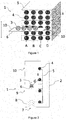
- FIG. 1 shows a schematic perspective view and Figure 2 shows a schematic side view of an example of a transducer 1.
- the transducer 1 has a container or housing 2 for containing the operative parts of the transducer 1.
- the housing 2 is preferably formed of a strong material that is also light weight and is capable of withstanding operation at high temperatures. A number of plastics or metals are suitable for example. A preferred material is graphene. Graphene is formed of one or more layers of carbon atoms arranged in a repeating hexagonal pattern and is known to be a very strong, lightweight and durable material despite having atomic level thickness, and is capable of withstanding operation or use at high temperatures. Other so-called 2D topological materials or "single layer" materials may be used.
- the housing 2 is not indicated in other figures for reasons of clarity.
- the transducer 1 has at least one molecule 3 of a first type and a plurality of molecules 4 of a second type.
- the molecules 3, 4 of the first and second types are capable of energy transfer according to Förster Resonance Energy Transfer (FRET). Accordingly, one of the first type and second type of molecule is a donor molecule and the other of the first type and second type of molecule is an acceptor molecule. That is, the molecule 3 of the first type may be a donor molecule and the molecules 4 of the second type may be acceptor molecules or vice versa.
- FRET Förster Resonance Energy Transfer
- the molecule 3 of the first type is a donor molecule or an acceptor molecule and, correspondingly, the molecules 4 of the second type are acceptor molecules or donor molecules is a design choice, depending on for example the properties required of the transducer 1 and on manufacturing convenience.
- the molecules 4 of the second type being acceptor molecules 4, it being understood that the roles may be reversed in other examples.
- Adjacent pairs of acceptor molecules 4 are spaced from each other by a spacing or separation s .
- the donor molecule 3 is movable across the acceptor molecules 4 in sequence, as indicated by arrows in Figures 1 and 2 .
- the separation s between pairs of adjacent acceptor molecules 4 may be the same or may be different.
- the separation s between adjacent acceptor molecules 4 may be determined so as to achieve desired properties for the light that is emitted by the acceptor molecules 4, as discussed further below.
- the separation s is preferably greater than the average Förster radius, i.e. greater than around 10 nm, in order to create independent resonance energy transfer floors or layers in the transducer 1.
- acceptor molecules 4 there may be plural sets of acceptor molecules 4, with four sets being shown by way of example and indicated by A, B, C, D. Within each set, the acceptor molecules 4 are arranged linearly in this example. Other non-linear arrangements, for some or all of the sets, may be used, depending on for example the properties required of the transducer 1.
- a respective donor molecule 3 is provided for each set of acceptor molecules 4.
- the separation s between pairs of adjacent acceptor molecules 4 within a set may be the same or may be different.
- the separation s between pairs of adjacent acceptor molecules 4 may be the same or may be different across different sets A, B, C, D... of acceptor molecules 4.
- acceptor molecules 4 there may be a single set of acceptor molecules 4 and a single donor molecule 3 or plural sets of acceptor molecules 4 and a corresponding number of donor molecules 3.
- the description will largely be in terms of one donor molecule 3 moving across one set of acceptor molecules 4 for convenience and brevity.
- the acceptor molecules 4 are supported or carried by a substrate 5.
- the acceptor molecule substrate 5 is preferably formed of a strong material that is also light weight and is capable of withstanding operation at high temperatures. A number of plastics or metals are suitable for example. However, a preferred material is a so-called 2D topological material or "single layer" material. Examples include graphene, MoS 2 , black phosphorus or phosphorene, etc.
- the donor molecule 3 is supported or carried by another substrate 6. Where there are plural donor molecules 3, they may be provided on their own separate substrates 6, or two or more, and in some examples all, of the donor molecules 3 may be provided on the same substrate 6.
- the donor molecule substrate 6 is movable so as to move the donor molecule 3 across the acceptor molecules 4 in sequence.
- the transducer 1 is arranged so that the donor molecule substrate 6 is movable by an incoming pressure wave, such as a sound wave.
- the housing 2 may have an opening 7 arranged generally along the direction of movement of the donor molecule substrate 6 to admit a sound wave 8 into the housing 2 to bear on the donor molecule substrate 6.
- the transducer 1 is arranged so that light can be incident on the donor molecule 3.
- the light may be ambient light, which means that the transducer 1 requires no power and may be a passive device.
- the incident light may be from a specific light source (not shown) which may be electrically powered for example.
- the transducer 1 in this example has one or more entrance windows 9 for admitting light to be incident on the donor molecule 3. The light that is incident on the donor molecule 3 causes the donor molecule 3 to transition to an electronic excited state.
- the donor molecule 3 As the donor molecule substrate 6 moves, the donor molecule 3 is driven to move across the acceptor molecules 4 in sequence. As discussed above, when the electronically excited donor molecule 3 is sufficiently close to an acceptor molecule 4, such as within a distance of for example 1 to 10nm or so, energy transfer according to FRET takes place. That is, once the distance d between the donor molecule 3 and an acceptor molecule 4 is less than the minimum distance required for FRET, energy is transferred by the donor molecule 3 emitting a photon that is accepted by the corresponding acceptor molecule 4. When the acceptor molecule 4 receives or accepts the photon emitted by the donor molecule, the acceptor molecule 4 enters an electron excited state.
- FRET Fluorescence Activated Reassisted Reassisted Reassisted Reassisted Reassisted Reassisted Reassisted Reassisted Reassisted Reassisted Reassisted Reassisted Reassisted Reassisted Reassisted Reassisted Reassisted Reassisted Reassisted Reassisted Reassisted Reassisted Reassisted Reassisted Reassisted Reassisted by the donor molecule 3
- the acceptor molecule 4 spontaneously relaxes to a lower state or a rest state by emitting a (real) photon.
- the photon emitted by the acceptor molecule 4 leaves the housing 2 through an exit window 10.
- At least one window may be both an entrance window for admitting light and an exit window for allowing generated light to exit the housing 2.
- the housing 2 may be for example entirely open or transparent to light (at least at the relevant frequencies) at least along one side or entirely. The important thing is that light can enter the housing 2 and can leave the housing 2.
- a sound wave 8 is used to drive the movement of the donor molecule 3, the transducer 1 may be regarded as an acousto-optic transducer.
- the transducer 1 may be manufactured at approximately nanoscale dimensions.
- the sensitivity of the transducer 1 to different volumes (amplitudes) of sound may be set or varied by for example setting or varying the maximum and/or minimum separation between the donor molecule 3 and the acceptor molecules 4 as the donor molecule 3 moves across the acceptor molecules 4.
- the substrate 6 for the donor molecule 3 is elastically deformable. That is, the donor molecule substrate 6 may be resilient so as to flex and return to its rest position on application and removal of a force, such as by a sound wave entering the transducer 1.
- the donor molecule substrate 6 may be a membrane, that is, a pliable sheet-like structure.
- the donor molecule substrate 6 may be formed of a metal or plastics for example. However, a preferred material is a so-called 2D topological material or "single layer" material. Examples include graphene, MoS 2 , black phosphorus or phosphorene, etc.
- Graphene is formed of one or more layers of carbon atoms arranged in a repeating hexagonal pattern and is known to be a very strong, lightweight and durable material despite having atomic level thickness, and is capable of withstanding operation or use at high temperatures, and so is particularly suitable for the donor molecule substrate 6.
- the donor molecule substrate 6 may be fixed at opposed edges 10, for example by fixing the opposed edges 10 to the housing 2.
- the effect of this on the donor molecule substrate 6 is shown schematically in Figures 3 and 4 .
- a pressure wave such as a sound wave
- the donor molecule substrate 6 flexes or bows at the centre, as indicated by arrows.
- the donor molecule substrate 6 returns to its rest position and then continues to move so as to bow in the opposite direction.
- the result of this is that the movement of the donor molecule substrate 6 in this example is a reciprocating back-and-forth bowing of the body or centre of the donor molecule substrate 6.
- the amplitude a of the movement will be determined by the material and dimensions of the donor molecule substrate 6, as well as by the amplitude and frequency of the incoming sound wave, and so can be controlled accordingly.
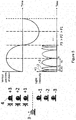
- the left hand side of Figure 5 shows schematically a donor molecule 6 moving back and forth over a succession of spatially separated acceptor molecules 4.
- acceptor molecules 4 which are numbered -3, -2, -1, +1, +2, +3, with no acceptor molecule 4 at the base or zero location. More or fewer acceptor molecules 4 may be provided in other examples and there may be an acceptor molecule 4 at the base or zero location in other examples.
- the right hand side of Figure 5 illustrates at the top the displacement of the donor molecule 3 from its rest position with respect to time and at the bottom the corresponding intensity of light that is emitted by the acceptor molecules 4 with respect to time.
- the donor molecule substrate 6 is at its rest position and is driven by an incoming sound wave and so moves the donor molecule 3 towards the acceptor molecule 4 at position +1.
- FRET takes place, resulting in the acceptor molecule 4 at position +1 emitting light.
- the donor molecule 3 continues moving and so moves away from the acceptor molecule 4 at position +1, which stops emitting light.
- Continued movement of the donor molecule 3 brings the donor molecule 3 close to the acceptor molecule 4 at position +2, such that FRET takes place and light is emitted by the acceptor molecule 4 at position +2.
- the donor molecule 3 continues to move in the same direction such that the acceptor molecule 4 at position +2 and then the acceptor molecule 4 at position +3 is caused to emit light.
- the movement of the substrate 6 and the donor molecule 3 ceases and the resilience of the substrate 6 drives the substrate 6 and the donor molecule back in the opposite direction, back towards the rest or zero position.
- the substrate 6 continues to move in that direction, and so is brought into proximity to the acceptor molecules 4 at positions -1, -2, -3 in turn, which therefore emit light in turn.
- the reciprocating movement of the substrate 6 may continue so as to drive the donor molecule 3 back and forth over the acceptor molecules 4, at least until for example friction or damping losses or the like cause the substrate 6 to cease its reciprocating movement and/or another sound wave is incident on the substrate 6 to begin another process of movement back and forth.
- the reciprocating movement of the substrate 6 and therefore the donor molecule 3 means that the donor molecule 3 is moving with a high speed when near the rest or zero position, and its speed drops to zero at the extremes of the movement of the substrate 6. (In the ideal case, this is in effect a simple harmonic oscillator motion, though in practice will be a damped oscillator motion.)
- the result of this on the intensity of the light that is emitted can be seen in the graph at the bottom of the right hand side of Figure 5 .
- the width or period P of the pulses of light emitted in turn by the acceptor molecules 4 varies, from a minimum of P1 for the acceptor molecule 4 at positions -1 and +1 to a minimum of P3 for the acceptor molecule 4 at positions -3 and +3. That is, the intensity of the light that is emitted by the acceptor molecules 4 is modulated.
- the modulation frequency is 2N A x f where N A is the number of acceptor molecules 4 over which the donor molecule 3 passes and f is the mechanical resonant frequency of the donor molecule substrate 6, the factor 2 arising because the donor molecule 3 moves over each acceptor molecule twice in a cycle.
- the separation s between adjacent pairs of acceptor molecules 4 is preferably greater than the average Förster radius, i.e. greater than around 10 nm, in order to create independent resonance energy transfer floors or layers in the transducer 1.
- the resulting modulation frequency decreases, and so there is a balance to be made. In any event, this arrangement operates in effect as a frequency multiplier, on a nanometre scale, which is beneficial for a number of applications.
- the donor molecule 3 may be the same type of molecule as the acceptor molecule 4, in which case they will (normally) emit light of the same wavelength.
- the donor molecules 3 and acceptor molecules 4 may be of different types, in which case they will typically emit light of different wavelengths.
- the type of molecule of the acceptor molecule 4 may be selected so as to produce a desired wavelength for the emitted light.
- the sets of acceptor molecules 4 A, B, C, D... may in general all be of the same type of material or different materials and the corresponding donor molecules 3 may in general all be of the same type of material or different materials.
- the sets of acceptor molecules 4 A, B, C, D... may be of different materials which are selected so that the different sets of acceptor molecules emit light of different wavelengths.
- At least one of the donor molecule 3 and the acceptor molecules 4 may be an inorganic compound of a group 12 element with a group 16 element (in other words, a compound of a group IIB element with a group VIB element under the former IUPAC group IUPAC group nomenclature).
- Such II-VI compounds have desirable optical properties, which can be engineered to suit different applications.
- the inorganic compound may be selected from a group consisting of cadmium sulphide, cadmium selenide, zinc sulphide and zinc selenide.
- the donor molecule 3 and the acceptor molecules may be an organic compound.
- the organic compound may be selected from a group consisting of a fluorescent protein and a rylene dye.
- At least one of the donor molecule 3 and the acceptor molecules 4 may be in the form of a quantum dot.
- a quantum dot is a nanoscale particle having quantum properties, which may include their optical and/or electronic properties, which differ from the properties of particles made of similar materials, but at larger scales, as a result of quantum effects.
- at least one of the donor molecule 3 and the acceptor molecules may be coated onto a nanoscale particle or otherwise embodied as a quantum dot, and the optical properties of the donor molecule 3 and/or of the acceptor molecule 4 may be varied according to choice, by adjusting one or more properties of the nanoscale particles, such as their size and/or shape.
- the window or windows 9, 10 may be provided with a filter and/or a lens. These allow the properties of the light incident on the donor molecule 4 and the light emitted by the acceptor molecules 4 to be controlled accordingly.
- transducers 1 as described herein may be used in a number of applications. This includes for example energy harvesting, by which the energy from a sound wave is converted into light energy which in turn may be converted into electric energy by the photoelectric effect if caused to be incident on a suitable material.
- the transducers 1 as described herein may be used in nanoscale communication; in nanoscale networks; in biomedical nanoscale systems; as a sensor with acousto-optic sensing capability; in visible light communication, to improve the modulated light frequency; in nano photonics chips; in conjunction with LEDs to improve their modulation speeds; etc.
- Another application is for lighting effects, where for example the incident sound wave is music and the transducer 1 can produce lighting effects that mirror of follow the changing music (it being understood that the light emitted by the acceptor molecules 4 would typically be in the visible and/or ultra violet part of the spectrum in such an application).
Landscapes
- Physics & Mathematics (AREA)
- General Physics & Mathematics (AREA)
- Electrostatic, Electromagnetic, Magneto- Strictive, And Variable-Resistance Transducers (AREA)
Abstract
Description
- The present disclosure relates to a transducer and method for converting mechanical energy to light energy.
- A number of techniques and devices for converting mechanical energy to light energy are known. As a particular example, techniques and devices for converting mechanical energy in the form of sound energy, or sound waves, to light energy are known. However, the known techniques and devices for converting mechanical energy to light energy, including for converting sound energy in particular to light energy, have various problems and limitations.
- According to a first aspect disclosed herein, there is provided a transducer for converting mechanical energy to light energy, the transducer comprising:
- at least one molecule of a first type; and
- a plurality of molecules of a second type, the molecules of the second type being spaced from each other;
- the molecules of the first and second types being capable of energy transfer according to Förster Resonance Energy Transfer wherein one of the first type and second type of molecule is a donor molecule and the other of the first type and second type of molecule is an acceptor molecule;
- the transducer being arranged such that the molecule of the first type is movable across the molecules of the second type in sequence so as to enable energy transfer according to Förster Resonance Energy Transfer between the molecule of the first type and the molecules of the second type in sequence thereby to cause the acceptor molecule or molecules to emit light.
- In examples, the molecule of the first type is movable so as to traverse the molecules of the second type in sequence. The movement may be for example a back-and-forth or reciprocating movement of the molecule, as discussed further below.
- In an example, the first type of molecule is a donor molecule and the second type of molecule is an acceptor molecule, whereby movement of the donor molecule across the acceptor molecules in sequence causes the acceptor molecules to emit light in sequence.
- In an example, the transducer comprises a substrate on which the molecule of the first type is carried, the substrate being movable so as to move the molecule of the first type across the molecules of the second type in sequence. The substrate may be elastically deformable. The substrate may be a membrane, that is, a pliable sheet-like structure. A number of plastics or metals are suitable for example. However, a preferred material is a so-called 2D topological material or "single layer" material. Examples include graphene, MoS2, black phosphorus or phosphorene, etc. Graphene is formed of one or more layers of carbon atoms arranged in a repeating hexagonal pattern and is known to be a very strong, lightweight and durable material despite having atomic level thickness, and is capable of withstanding operation or use at high temperatures.
- In an example, the substrate is fixed at opposed edges. In this example, movement of the substrate is a reciprocating back-and-forth bowing of the body of the substrate.
- In an example, the transducer comprises a housing in which the substrate is located, the housing having an opening for admitting a pressure wave which in use drives movement of the molecule of the first type. The pressure wave may be for example a sound wave.
- In an example, the housing comprises at least one window for admitting light for exciting the or each donor molecule. In an example, the housing comprises at least one window for allowing light generated by the or each acceptor molecule to exit the housing. There may for example be one window that both admits light and allows light to exit. Alternatively, there may for example be at least one window for admitting light and at least one separate window for allowing light to exit.
- In an example, the transducer comprises plural molecules of the first type.
- According to a second aspect disclosed herein, there is provided a method of converting mechanical energy to light energy, the method comprising:
- moving a molecule of a first type across molecules of a second type in sequence, wherein the molecules of the first and second types are capable of energy transfer according to Förster Resonance Energy Transfer wherein one of the first type and second type of molecule is a donor molecule and the other of the first type and second type of molecule is an acceptor molecule, and wherein the molecules of the second type are spaced from each other, whereby the moving the molecule of the first type brings the molecule of the first type close to the molecules of the second type in sequence so as to enable energy transfer according to Förster Resonance Energy Transfer between the molecule of the first type and the molecules of the second type in sequence, thereby to cause the acceptor molecule or molecules to emit light.
- In an example, the first type of molecule is a donor molecule and the second type of molecule is an acceptor molecule, whereby moving the donor molecule across the acceptor molecules in sequence causes the acceptor molecules to emit light in sequence.
- In an example, the molecule of the first type is carried on a substrate and the moving comprises moving the substrate so as to move the molecule of the first type across the molecules of the second type in sequence. In an example, the substrate is moved by a sound wave incident on the substrate.
- In an example, the substrate is elastically deformable and is fixed at opposed edges such that movement of the substrate is a reciprocating, bowing back-and-forth of the body of the substrate.
- In an example, plural molecules of the first type are moved across molecules of the second type in sequence.
- To assist understanding of the present disclosure and to show how embodiments may be put into effect, reference is made by way of example to the accompanying drawings in which:
-
Figure 1 shows a schematic perspective view of an example of a transducer; -
Figure 2 shows a schematic side view of an example of a transducer; -
Figure 3 shows schematically an example of movement of a donor molecule and a donor molecule substrate; -
Figure 4 shows schematically an example of movement of a donor molecule; and -
Figure 5 shows schematically an example of movement of a donor molecule over acceptor molecules and the intensity of the light emitted by the acceptor molecules. - By way of introduction first, reference is made to the known "Förster Resonance Energy Transfer" (FRET). In FRET, energy is transferred from a first light-sensitive molecule (the "donor" molecule) to a second light-sensitive molecule (the "acceptor" molecule). The donor molecule is initially in an electronic excited state, and may be put into that excited state by light that is incident on the donor molecule. When the donor molecule is sufficiently close to the acceptor molecule, energy of the excited donor molecule is transferred to the acceptor molecule through non-radiative dipole-dipole coupling. The acceptor molecule may then emit light as a result. The efficiency of the energy transfer from the donor molecule to the acceptor molecule is inversely proportional to the sixth power of the distance between the donor molecule and the acceptor molecule. This means that FRET is extremely sensitive to small changes in distance between the donor molecule and the acceptor molecule. The distance between the donor molecule and the acceptor molecule for FRET to take place is much less than the wavelength of the light that is transferred, and may be in the range of for example 1 to 10nm or so.
- In some examples described herein, a transducer is provided for converting mechanical energy to light energy. The transducer has at least one molecule of a first type and a plurality of molecules of a second type. The molecules of the first and second types are capable of energy transfer according to FRET. One of the first type and second type of molecule is a donor molecule and the other of the first type and second type of molecule is an acceptor molecule. The molecules of the second type are spaced from each other. The molecule of the first type is movable across the molecules of the second type in sequence. This enables energy transfer according to FRET between the molecule of the first type and the molecules of the second type in sequence thereby to cause the acceptor molecule or molecules to emit light. That is, the molecule of the first type is movable so as to traverse the molecules of the second type in sequence. The movement may in effect be a back-and-forth or reciprocating movement of the molecule. In the case that the first type of molecule is a donor molecule and the second type of molecule is an acceptor molecule, movement of the donor molecule across the acceptor molecules in sequence causes the acceptor molecules to emit light in sequence.
- Referring now to the drawings, examples of a transducer according to embodiments will be described.
-
Figure 1 shows a schematic perspective view andFigure 2 shows a schematic side view of an example of atransducer 1. The figures are not to scale and each shows only a portion of thetransducer 1. Thetransducer 1 has a container orhousing 2 for containing the operative parts of thetransducer 1. Thehousing 2 is preferably formed of a strong material that is also light weight and is capable of withstanding operation at high temperatures. A number of plastics or metals are suitable for example. A preferred material is graphene. Graphene is formed of one or more layers of carbon atoms arranged in a repeating hexagonal pattern and is known to be a very strong, lightweight and durable material despite having atomic level thickness, and is capable of withstanding operation or use at high temperatures. Other so-called 2D topological materials or "single layer" materials may be used. Thehousing 2 is not indicated in other figures for reasons of clarity. - The
transducer 1 has at least onemolecule 3 of a first type and a plurality ofmolecules 4 of a second type. Themolecules molecule 3 of the first type may be a donor molecule and themolecules 4 of the second type may be acceptor molecules or vice versa. Whether themolecule 3 of the first type is a donor molecule or an acceptor molecule and, correspondingly, themolecules 4 of the second type are acceptor molecules or donor molecules is a design choice, depending on for example the properties required of thetransducer 1 and on manufacturing convenience. For convenience and brevity, reference will be made herein to the molecule(s) 3 of the first type being a donor molecule(s) 3 and themolecules 4 of the second type beingacceptor molecules 4, it being understood that the roles may be reversed in other examples. - Adjacent pairs of
acceptor molecules 4 are spaced from each other by a spacing or separation s. Thedonor molecule 3 is movable across theacceptor molecules 4 in sequence, as indicated by arrows inFigures 1 and 2 . The separation s between pairs ofadjacent acceptor molecules 4 may be the same or may be different. The separation s betweenadjacent acceptor molecules 4 may be determined so as to achieve desired properties for the light that is emitted by theacceptor molecules 4, as discussed further below. The separation s is preferably greater than the average Förster radius, i.e. greater than around 10 nm, in order to create independent resonance energy transfer floors or layers in thetransducer 1. - Referring particularly to
Figure 2 , there may be plural sets ofacceptor molecules 4, with four sets being shown by way of example and indicated by A, B, C, D. Within each set, theacceptor molecules 4 are arranged linearly in this example. Other non-linear arrangements, for some or all of the sets, may be used, depending on for example the properties required of thetransducer 1. Arespective donor molecule 3 is provided for each set ofacceptor molecules 4. The separation s between pairs ofadjacent acceptor molecules 4 within a set may be the same or may be different. The separation s between pairs ofadjacent acceptor molecules 4 may be the same or may be different across different sets A, B, C, D... ofacceptor molecules 4. Thus, there may be a single set ofacceptor molecules 4 and asingle donor molecule 3 or plural sets ofacceptor molecules 4 and a corresponding number ofdonor molecules 3. In some examples, there may beplural donor molecules 3 for moving across a single set ofacceptor molecules 4. In the following, the description will largely be in terms of onedonor molecule 3 moving across one set ofacceptor molecules 4 for convenience and brevity. - The
acceptor molecules 4 are supported or carried by asubstrate 5. Theacceptor molecule substrate 5 is preferably formed of a strong material that is also light weight and is capable of withstanding operation at high temperatures. A number of plastics or metals are suitable for example. However, a preferred material is a so-called 2D topological material or "single layer" material. Examples include graphene, MoS2, black phosphorus or phosphorene, etc. - The
donor molecule 3 is supported or carried by anothersubstrate 6. Where there areplural donor molecules 3, they may be provided on their ownseparate substrates 6, or two or more, and in some examples all, of thedonor molecules 3 may be provided on thesame substrate 6. - The
donor molecule substrate 6 is movable so as to move thedonor molecule 3 across theacceptor molecules 4 in sequence. In an example, thetransducer 1 is arranged so that thedonor molecule substrate 6 is movable by an incoming pressure wave, such as a sound wave. For example, thehousing 2 may have anopening 7 arranged generally along the direction of movement of thedonor molecule substrate 6 to admit asound wave 8 into thehousing 2 to bear on thedonor molecule substrate 6. - The
transducer 1 is arranged so that light can be incident on thedonor molecule 3. Depending on the material of thedonor molecule 3 and/or specific requirements, the light may be ambient light, which means that thetransducer 1 requires no power and may be a passive device. Alternatively or additionally, the incident light may be from a specific light source (not shown) which may be electrically powered for example. Thetransducer 1 in this example has one ormore entrance windows 9 for admitting light to be incident on thedonor molecule 3. The light that is incident on thedonor molecule 3 causes thedonor molecule 3 to transition to an electronic excited state. - As the
donor molecule substrate 6 moves, thedonor molecule 3 is driven to move across theacceptor molecules 4 in sequence. As discussed above, when the electronicallyexcited donor molecule 3 is sufficiently close to anacceptor molecule 4, such as within a distance of for example 1 to 10nm or so, energy transfer according to FRET takes place. That is, once the distance d between thedonor molecule 3 and anacceptor molecule 4 is less than the minimum distance required for FRET, energy is transferred by thedonor molecule 3 emitting a photon that is accepted by thecorresponding acceptor molecule 4. When theacceptor molecule 4 receives or accepts the photon emitted by the donor molecule, theacceptor molecule 4 enters an electron excited state. (In fact, FRET is analogous to near-field communication, in that the radius of interaction is much smaller than the wavelength of light emitted. As such, the photon that is emitted by thedonor molecule 3 is a virtual photon which is instantly absorbed by a receivingacceptor molecule 4.) Subsequently, and typically practically instantaneously, theacceptor molecule 4 spontaneously relaxes to a lower state or a rest state by emitting a (real) photon. The photon emitted by theacceptor molecule 4 leaves thehousing 2 through anexit window 10. There may be one ormore exit windows 10. For example, there may be oneexit window 10 for eachacceptor molecule 4. At least one window may be both an entrance window for admitting light and an exit window for allowing generated light to exit thehousing 2. Thehousing 2 may be for example entirely open or transparent to light (at least at the relevant frequencies) at least along one side or entirely. The important thing is that light can enter thehousing 2 and can leave thehousing 2. As in this example asound wave 8 is used to drive the movement of thedonor molecule 3, thetransducer 1 may be regarded as an acousto-optic transducer. - This arrangement has a number of advantages in this respect. The
transducer 1 may be manufactured at approximately nanoscale dimensions. The sensitivity of thetransducer 1 to different volumes (amplitudes) of sound may be set or varied by for example setting or varying the maximum and/or minimum separation between thedonor molecule 3 and theacceptor molecules 4 as thedonor molecule 3 moves across theacceptor molecules 4. - In an example, the
substrate 6 for thedonor molecule 3 is elastically deformable. That is, thedonor molecule substrate 6 may be resilient so as to flex and return to its rest position on application and removal of a force, such as by a sound wave entering thetransducer 1. Thedonor molecule substrate 6 may be a membrane, that is, a pliable sheet-like structure. Thedonor molecule substrate 6 may be formed of a metal or plastics for example. However, a preferred material is a so-called 2D topological material or "single layer" material. Examples include graphene, MoS2, black phosphorus or phosphorene, etc. Graphene is formed of one or more layers of carbon atoms arranged in a repeating hexagonal pattern and is known to be a very strong, lightweight and durable material despite having atomic level thickness, and is capable of withstanding operation or use at high temperatures, and so is particularly suitable for thedonor molecule substrate 6. - The
donor molecule substrate 6 may be fixed atopposed edges 10, for example by fixing theopposed edges 10 to thehousing 2. The effect of this on thedonor molecule substrate 6 is shown schematically inFigures 3 and 4 . As a pressure wave, such as a sound wave, bears on thedonor molecule substrate 6, thedonor molecule substrate 6 flexes or bows at the centre, as indicated by arrows. Then, owing to the resilience of thedonor molecule substrate 6, thedonor molecule substrate 6 returns to its rest position and then continues to move so as to bow in the opposite direction. The result of this is that the movement of thedonor molecule substrate 6 in this example is a reciprocating back-and-forth bowing of the body or centre of thedonor molecule substrate 6. The amplitude a of the movement will be determined by the material and dimensions of thedonor molecule substrate 6, as well as by the amplitude and frequency of the incoming sound wave, and so can be controlled accordingly. - The effect of this on the light emitted by the
acceptor molecules 4 will be discussed with reference toFigure 5 . The left hand side ofFigure 5 shows schematically adonor molecule 6 moving back and forth over a succession of spatially separatedacceptor molecules 4. In this example, there are sixacceptor molecules 4 which are numbered -3, -2, -1, +1, +2, +3, with noacceptor molecule 4 at the base or zero location. More orfewer acceptor molecules 4 may be provided in other examples and there may be anacceptor molecule 4 at the base or zero location in other examples. The right hand side ofFigure 5 illustrates at the top the displacement of thedonor molecule 3 from its rest position with respect to time and at the bottom the corresponding intensity of light that is emitted by theacceptor molecules 4 with respect to time. - Starting at time zero, the
donor molecule substrate 6 is at its rest position and is driven by an incoming sound wave and so moves thedonor molecule 3 towards theacceptor molecule 4 at position +1. When thedonor molecule 3 is close enough to theacceptor molecule 4 at position +1, FRET takes place, resulting in theacceptor molecule 4 at position +1 emitting light. Thedonor molecule 3 continues moving and so moves away from theacceptor molecule 4 at position +1, which stops emitting light. Continued movement of thedonor molecule 3 brings thedonor molecule 3 close to theacceptor molecule 4 at position +2, such that FRET takes place and light is emitted by theacceptor molecule 4 at position +2. In this example, thedonor molecule 3 continues to move in the same direction such that theacceptor molecule 4 at position +2 and then theacceptor molecule 4 at position +3 is caused to emit light. At this point in this example, the movement of thesubstrate 6 and thedonor molecule 3 ceases and the resilience of thesubstrate 6 drives thesubstrate 6 and the donor molecule back in the opposite direction, back towards the rest or zero position. Thesubstrate 6 continues to move in that direction, and so is brought into proximity to theacceptor molecules 4 at positions -1, -2, -3 in turn, which therefore emit light in turn. The reciprocating movement of thesubstrate 6 may continue so as to drive thedonor molecule 3 back and forth over theacceptor molecules 4, at least until for example friction or damping losses or the like cause thesubstrate 6 to cease its reciprocating movement and/or another sound wave is incident on thesubstrate 6 to begin another process of movement back and forth. - The reciprocating movement of the
substrate 6 and therefore thedonor molecule 3 means that thedonor molecule 3 is moving with a high speed when near the rest or zero position, and its speed drops to zero at the extremes of the movement of thesubstrate 6. (In the ideal case, this is in effect a simple harmonic oscillator motion, though in practice will be a damped oscillator motion.) The result of this on the intensity of the light that is emitted can be seen in the graph at the bottom of the right hand side ofFigure 5 . It will be seen immediately that the width or period P of the pulses of light emitted in turn by theacceptor molecules 4 varies, from a minimum of P1 for theacceptor molecule 4 at positions -1 and +1 to a minimum of P3 for theacceptor molecule 4 at positions -3 and +3. That is, the intensity of the light that is emitted by theacceptor molecules 4 is modulated. In the ideal case (with no losses due to damping, etc.), the modulation frequency is 2NA x f where NA is the number ofacceptor molecules 4 over which thedonor molecule 3 passes and f is the mechanical resonant frequency of thedonor molecule substrate 6, thefactor 2 arising because thedonor molecule 3 moves over each acceptor molecule twice in a cycle. It may be noted that if the amplitude of movement of thedonor molecule substrate 6 is large, particularly much larger than the minimum distance required for FRET to take place (which is typically around 1 to 10nm as discussed above), then there may be a correspondingly large number NA ofacceptor molecules 4 over which thedonor molecule 3 moves, resulting in a high modulation frequency. As mentioned, the separation s between adjacent pairs ofacceptor molecules 4 is preferably greater than the average Förster radius, i.e. greater than around 10 nm, in order to create independent resonance energy transfer floors or layers in thetransducer 1. However, as the separation s increases, the resulting modulation frequency decreases, and so there is a balance to be made. In any event, this arrangement operates in effect as a frequency multiplier, on a nanometre scale, which is beneficial for a number of applications. - The
donor molecule 3 may be the same type of molecule as theacceptor molecule 4, in which case they will (normally) emit light of the same wavelength. Alternatively, thedonor molecules 3 andacceptor molecules 4 may be of different types, in which case they will typically emit light of different wavelengths. The type of molecule of theacceptor molecule 4 may be selected so as to produce a desired wavelength for the emitted light. Where plural sets of acceptor molecules 4 A, B, C, D... andcorresponding donor molecules 3 are provided, the sets of acceptor molecules 4 A, B, C, D... may in general all be of the same type of material or different materials and thecorresponding donor molecules 3 may in general all be of the same type of material or different materials. - Where plural sets of acceptor molecules 4 A, B, C, D... and
corresponding donor molecules 3 are provided, the sets of acceptor molecules 4 A, B, C, D... may be of different materials which are selected so that the different sets of acceptor molecules emit light of different wavelengths. - At least one of the
donor molecule 3 and theacceptor molecules 4 may be an inorganic compound of a group 12 element with a group 16 element (in other words, a compound of a group IIB element with a group VIB element under the former IUPAC group IUPAC group nomenclature). Such II-VI compounds have desirable optical properties, which can be engineered to suit different applications. As particular examples, the inorganic compound may be selected from a group consisting of cadmium sulphide, cadmium selenide, zinc sulphide and zinc selenide. - Alternatively or additionally, at least one of the
donor molecule 3 and the acceptor molecules may be an organic compound. This has the advantage of allowing the acousto-optic transducer 1 to be used in biochemical, biomedical, genetic and other bioengineering applications. As particular examples, the organic compound may be selected from a group consisting of a fluorescent protein and a rylene dye. - At least one of the
donor molecule 3 and theacceptor molecules 4 may be in the form of a quantum dot. A quantum dot is a nanoscale particle having quantum properties, which may include their optical and/or electronic properties, which differ from the properties of particles made of similar materials, but at larger scales, as a result of quantum effects. Thus, for example, at least one of thedonor molecule 3 and the acceptor molecules may be coated onto a nanoscale particle or otherwise embodied as a quantum dot, and the optical properties of thedonor molecule 3 and/or of theacceptor molecule 4 may be varied according to choice, by adjusting one or more properties of the nanoscale particles, such as their size and/or shape. - The window or
windows donor molecule 4 and the light emitted by theacceptor molecules 4 to be controlled accordingly. - Examples of
transducers 1 as described herein may be used in a number of applications. This includes for example energy harvesting, by which the energy from a sound wave is converted into light energy which in turn may be converted into electric energy by the photoelectric effect if caused to be incident on a suitable material. Thetransducers 1 as described herein may be used in nanoscale communication; in nanoscale networks; in biomedical nanoscale systems; as a sensor with acousto-optic sensing capability; in visible light communication, to improve the modulated light frequency; in nano photonics chips; in conjunction with LEDs to improve their modulation speeds; etc. Another application is for lighting effects, where for example the incident sound wave is music and thetransducer 1 can produce lighting effects that mirror of follow the changing music (it being understood that the light emitted by theacceptor molecules 4 would typically be in the visible and/or ultra violet part of the spectrum in such an application). - The examples described herein are to be understood as illustrative examples of embodiments of the invention. Further embodiments and examples are envisaged. Any feature described in relation to any one example or embodiment may be used alone or in combination with other features. In addition, any feature described in relation to any one example or embodiment may also be used in combination with one or more features of any other of the examples or embodiments, or any combination of any other of the examples or embodiments. Furthermore, equivalents and modifications not described herein may also be employed within the scope of the invention, which is defined in the claims.
Claims (15)
- A transducer for converting mechanical energy to light energy, the transducer comprising:at least one molecule of a first type; anda plurality of molecules of a second type, the molecules of the second type being spaced from each other;the molecules of the first and second types being capable of energy transfer according to Förster Resonance Energy Transfer wherein one of the first type and second type of molecule is a donor molecule and the other of the first type and second type of molecule is an acceptor molecule;the transducer being arranged such that the molecule of the first type is movable across the molecules of the second type in sequence so as to enable energy transfer according to Förster Resonance Energy Transfer between the molecule of the first type and the molecules of the second type in sequence thereby to cause the acceptor molecule or molecules to emit light.
- A transducer according to claim 1, wherein the first type of molecule is a donor molecule and the second type of molecule is an acceptor molecule, whereby movement of the donor molecule across the acceptor molecules in sequence causes the acceptor molecules to emit light in sequence.
- A transducer according to claim 1 or claim 2, comprising a substrate on which the molecule of the first type is carried, the substrate being movable so as to move the molecule of the first type across the molecules of the second type in sequence.
- A transducer according to claim 3, wherein the substrate is elastically deformable.
- A transducer according to claim 4, wherein the substrate is fixed at opposed edges.
- A transducer according to any of claims 1 to 5, wherein the transducer comprises a housing in which the substrate is located, the housing having an opening for admitting a pressure wave which in use drives movement of the molecule of the first type.
- A transducer according to claim 6, the housing comprising at least one window for admitting light for exciting the or each donor molecule.
- A transducer according to claim 6 or claim 7, the housing comprising at least one window for allowing light generated by the or each acceptor molecule to exit the housing.
- A transducer according to any of claims 1 to 8, comprising plural molecules of the first type.
- A method of converting mechanical energy to light energy, the method comprising:moving a molecule of a first type across molecules of a second type in sequence, wherein the molecules of the first and second types are capable of energy transfer according to Förster Resonance Energy Transfer wherein one of the first type and second type of molecule is a donor molecule and the other of the first type and second type of molecule is an acceptor molecule, and wherein the molecules of the second type are spaced from each other, whereby the moving the molecule of the first type brings the molecule of the first type close to the molecules of the second type in sequence so as to enable energy transfer according to Förster Resonance Energy Transfer between the molecule of the first type and the molecules of the second type in sequence, thereby to cause the acceptor molecule or molecules to emit light.
- A method according to claim 10, wherein the first type of molecule is a donor molecule and the second type of molecule is an acceptor molecule, whereby moving the donor molecule across the acceptor molecules in sequence causes the acceptor molecules to emit light in sequence.
- A method according to claim 10 or claim 11, wherein the molecule of the first type is carried on a substrate and the moving comprises moving the substrate so as to move the molecule of the first type across the molecules of the second type in sequence.
- A method according to claim 12, wherein the substrate is moved by a sound wave incident on the substrate.
- A method according to claim 12 or claim 13, wherein the substrate is elastically deformable and is fixed at opposed edges such that movement of the substrate is a reciprocating, bowing back-and-forth of the body of the substrate.
- A method according to any of claims 10 to 14, wherein plural molecules of the first type are moved across molecules of the second type in sequence.
Priority Applications (1)
| Application Number | Priority Date | Filing Date | Title |
|---|---|---|---|
| EP17172291.1A EP3407033B1 (en) | 2017-05-22 | 2017-05-22 | Transducer and method for converting mechanical energy to light energy |
Applications Claiming Priority (1)
| Application Number | Priority Date | Filing Date | Title |
|---|---|---|---|
| EP17172291.1A EP3407033B1 (en) | 2017-05-22 | 2017-05-22 | Transducer and method for converting mechanical energy to light energy |
Publications (2)
| Publication Number | Publication Date |
|---|---|
| EP3407033A1 true EP3407033A1 (en) | 2018-11-28 |
| EP3407033B1 EP3407033B1 (en) | 2022-07-27 |
Family
ID=59061782
Family Applications (1)
| Application Number | Title | Priority Date | Filing Date |
|---|---|---|---|
| EP17172291.1A Active EP3407033B1 (en) | 2017-05-22 | 2017-05-22 | Transducer and method for converting mechanical energy to light energy |
Country Status (1)
| Country | Link |
|---|---|
| EP (1) | EP3407033B1 (en) |
Citations (2)
| Publication number | Priority date | Publication date | Assignee | Title |
|---|---|---|---|---|
| WO2015061460A1 (en) * | 2013-10-23 | 2015-04-30 | Google Inc. | Non-invasive analyte detection system with modulation source |
| US20170020441A1 (en) * | 2015-07-24 | 2017-01-26 | Johnson & Johnson Vision Care, Inc. | Systems and biomedical devices for sensing and for biometric based information communication |
-
2017
- 2017-05-22 EP EP17172291.1A patent/EP3407033B1/en active Active
Patent Citations (2)
| Publication number | Priority date | Publication date | Assignee | Title |
|---|---|---|---|---|
| WO2015061460A1 (en) * | 2013-10-23 | 2015-04-30 | Google Inc. | Non-invasive analyte detection system with modulation source |
| US20170020441A1 (en) * | 2015-07-24 | 2017-01-26 | Johnson & Johnson Vision Care, Inc. | Systems and biomedical devices for sensing and for biometric based information communication |
Non-Patent Citations (2)
| Title |
|---|
| BURHAN GULBAHAR ET AL: "CSSTag: Optical Nanoscale Radar and Particle Tracking for In-Body and Microfluidic Systems with Vibrating Graphene and Resonance Energy Transfer", 4 September 2017 (2017-09-04), pages 1 - 13, XP055405824, Retrieved from the Internet <URL:https://arxiv.org/abs/1709.00907v1> [retrieved on 20170912] * |
| GULBAHAR BURHAN ET AL: "Nanoscale optical communications modulator and acousto-optic transduction with vibrating graphene and resonance energy transfer", 2017 IEEE INTERNATIONAL CONFERENCE ON COMMUNICATIONS (ICC), IEEE, 25 May 2017 (2017-05-25), pages 1 - 7, XP033132910, DOI: 10.1109/ICC.2017.7997036 * |
Also Published As
| Publication number | Publication date |
|---|---|
| EP3407033B1 (en) | 2022-07-27 |
Similar Documents
| Publication | Publication Date | Title |
|---|---|---|
| Xiao et al. | Recent progress in silicon‐based photonic integrated circuits and emerging applications | |
| Yadav et al. | Room temperature weak-to-strong coupling and the emergence of collective emission from quantum dots coupled to plasmonic arrays | |
| Xia et al. | Opto-mechanical photonic crystal cavities for sensing application | |
| Kurzmann et al. | Auger recombination in self-assembled quantum dots: quenching and broadening of the charged exciton transition | |
| Moczała-Dusanowska et al. | Strain-tunable single-photon source based on a quantum dot–micropillar system | |
| Park et al. | Polariton dynamics in two-dimensional Ruddlesden–Popper perovskites strongly coupled with plasmonic lattices | |
| US9499400B2 (en) | Optical devices and methods of controlling propagation directions of light from the optical devices | |
| Choi et al. | Perspective and potential of smart optical materials | |
| JP2017151442A (en) | Nanostructure material, methods, and devices | |
| Khelifa et al. | WSe2 light-emitting device coupled to an h-BN waveguide | |
| US7196349B2 (en) | Resonant cavity enhanced multi-quantum well light modulator and detector | |
| Ho et al. | Finite-area membrane metasurfaces for enhancing light-matter coupling in monolayer transition metal dichalcogenides | |
| EP3407033B1 (en) | Transducer and method for converting mechanical energy to light energy | |
| Bera et al. | Dirac point modulated self-powered ultrasensitive photoresponse and color-tunable electroluminescence from flexible graphene/metal–organic frameworks/graphene vertical phototransistor | |
| Al-Shammari et al. | Tunable wettability of ferroelectric lithium niobate surfaces: the role of engineered microstructure and tailored metallic nanostructures | |
| Lee et al. | Harvesting electrical energy using plasmon-enhanced light pressure in a platinum cut cone | |
| US9903816B2 (en) | Photonic crystal sensor structure and a method for manufacturing the same | |
| Pugliese et al. | Highly reflective periodic nanostructure based on thermal evaporated tungsten oxide and calcium fluoride for advanced photonic applications | |
| Gulbahar et al. | Nanoscale optical communications modulator and acousto-optic transduction with vibrating graphene and resonance energy transfer | |
| US20250025874A1 (en) | Apparatus and methods for performing microfluidic-based biochemical assays | |
| CN110582691B (en) | Acousto-optic transducers, arrays and methods | |
| Nagao et al. | Analysis of trap-state dynamics of single CdSe/ZnS quantum dots on a TiO2 substrate with different Nb concentrations | |
| Aubret et al. | Nondestructive encapsulation of CdSe/CdS quantum dots in an inorganic matrix by pulsed laser deposition | |
| Zhang et al. | InGaN/GaN micro mirror with electrostatic comb drive actuation integrated on a patterned silicon-on-insulator wafer | |
| See et al. | Quantum dot emission modulation using piezoelectric photonic crystal MEMS resonators |
Legal Events
| Date | Code | Title | Description |
|---|---|---|---|
| PUAI | Public reference made under article 153(3) epc to a published international application that has entered the european phase |
Free format text: ORIGINAL CODE: 0009012 |
|
| STAA | Information on the status of an ep patent application or granted ep patent |
Free format text: STATUS: THE APPLICATION HAS BEEN PUBLISHED |
|
| AK | Designated contracting states |
Kind code of ref document: A1 Designated state(s): AL AT BE BG CH CY CZ DE DK EE ES FI FR GB GR HR HU IE IS IT LI LT LU LV MC MK MT NL NO PL PT RO RS SE SI SK SM TR |
|
| AX | Request for extension of the european patent |
Extension state: BA ME |
|
| STAA | Information on the status of an ep patent application or granted ep patent |
Free format text: STATUS: REQUEST FOR EXAMINATION WAS MADE |
|
| 17P | Request for examination filed |
Effective date: 20190528 |
|
| RBV | Designated contracting states (corrected) |
Designated state(s): AL AT BE BG CH CY CZ DE DK EE ES FI FR GB GR HR HU IE IS IT LI LT LU LV MC MK MT NL NO PL PT RO RS SE SI SK SM TR |
|
| GRAP | Despatch of communication of intention to grant a patent |
Free format text: ORIGINAL CODE: EPIDOSNIGR1 |
|
| STAA | Information on the status of an ep patent application or granted ep patent |
Free format text: STATUS: GRANT OF PATENT IS INTENDED |
|
| INTG | Intention to grant announced |
Effective date: 20220218 |
|
| GRAS | Grant fee paid |
Free format text: ORIGINAL CODE: EPIDOSNIGR3 |
|
| GRAA | (expected) grant |
Free format text: ORIGINAL CODE: 0009210 |
|
| STAA | Information on the status of an ep patent application or granted ep patent |
Free format text: STATUS: THE PATENT HAS BEEN GRANTED |
|
| AK | Designated contracting states |
Kind code of ref document: B1 Designated state(s): AL AT BE BG CH CY CZ DE DK EE ES FI FR GB GR HR HU IE IS IT LI LT LU LV MC MK MT NL NO PL PT RO RS SE SI SK SM TR |
|
| REG | Reference to a national code |
Ref country code: CH Ref legal event code: EP |
|
| REG | Reference to a national code |
Ref country code: AT Ref legal event code: REF Ref document number: 1507348 Country of ref document: AT Kind code of ref document: T Effective date: 20220815 |
|
| REG | Reference to a national code |
Ref country code: DE Ref legal event code: R096 Ref document number: 602017059813 Country of ref document: DE |
|
| REG | Reference to a national code |
Ref country code: IE Ref legal event code: FG4D |
|
| REG | Reference to a national code |
Ref country code: LT Ref legal event code: MG9D |
|
| REG | Reference to a national code |
Ref country code: NL Ref legal event code: MP Effective date: 20220727 |
|
| PG25 | Lapsed in a contracting state [announced via postgrant information from national office to epo] |
Ref country code: SE Free format text: LAPSE BECAUSE OF FAILURE TO SUBMIT A TRANSLATION OF THE DESCRIPTION OR TO PAY THE FEE WITHIN THE PRESCRIBED TIME-LIMIT Effective date: 20220727 Ref country code: RS Free format text: LAPSE BECAUSE OF FAILURE TO SUBMIT A TRANSLATION OF THE DESCRIPTION OR TO PAY THE FEE WITHIN THE PRESCRIBED TIME-LIMIT Effective date: 20220727 Ref country code: PT Free format text: LAPSE BECAUSE OF FAILURE TO SUBMIT A TRANSLATION OF THE DESCRIPTION OR TO PAY THE FEE WITHIN THE PRESCRIBED TIME-LIMIT Effective date: 20221128 Ref country code: NO Free format text: LAPSE BECAUSE OF FAILURE TO SUBMIT A TRANSLATION OF THE DESCRIPTION OR TO PAY THE FEE WITHIN THE PRESCRIBED TIME-LIMIT Effective date: 20221027 Ref country code: NL Free format text: LAPSE BECAUSE OF FAILURE TO SUBMIT A TRANSLATION OF THE DESCRIPTION OR TO PAY THE FEE WITHIN THE PRESCRIBED TIME-LIMIT Effective date: 20220727 Ref country code: LV Free format text: LAPSE BECAUSE OF FAILURE TO SUBMIT A TRANSLATION OF THE DESCRIPTION OR TO PAY THE FEE WITHIN THE PRESCRIBED TIME-LIMIT Effective date: 20220727 Ref country code: LT Free format text: LAPSE BECAUSE OF FAILURE TO SUBMIT A TRANSLATION OF THE DESCRIPTION OR TO PAY THE FEE WITHIN THE PRESCRIBED TIME-LIMIT Effective date: 20220727 Ref country code: FI Free format text: LAPSE BECAUSE OF FAILURE TO SUBMIT A TRANSLATION OF THE DESCRIPTION OR TO PAY THE FEE WITHIN THE PRESCRIBED TIME-LIMIT Effective date: 20220727 Ref country code: ES Free format text: LAPSE BECAUSE OF FAILURE TO SUBMIT A TRANSLATION OF THE DESCRIPTION OR TO PAY THE FEE WITHIN THE PRESCRIBED TIME-LIMIT Effective date: 20220727 |
|
| REG | Reference to a national code |
Ref country code: AT Ref legal event code: MK05 Ref document number: 1507348 Country of ref document: AT Kind code of ref document: T Effective date: 20220727 |
|
| PG25 | Lapsed in a contracting state [announced via postgrant information from national office to epo] |
Ref country code: PL Free format text: LAPSE BECAUSE OF FAILURE TO SUBMIT A TRANSLATION OF THE DESCRIPTION OR TO PAY THE FEE WITHIN THE PRESCRIBED TIME-LIMIT Effective date: 20220727 Ref country code: IS Free format text: LAPSE BECAUSE OF FAILURE TO SUBMIT A TRANSLATION OF THE DESCRIPTION OR TO PAY THE FEE WITHIN THE PRESCRIBED TIME-LIMIT Effective date: 20221127 Ref country code: HR Free format text: LAPSE BECAUSE OF FAILURE TO SUBMIT A TRANSLATION OF THE DESCRIPTION OR TO PAY THE FEE WITHIN THE PRESCRIBED TIME-LIMIT Effective date: 20220727 Ref country code: GR Free format text: LAPSE BECAUSE OF FAILURE TO SUBMIT A TRANSLATION OF THE DESCRIPTION OR TO PAY THE FEE WITHIN THE PRESCRIBED TIME-LIMIT Effective date: 20221028 |
|
| PG25 | Lapsed in a contracting state [announced via postgrant information from national office to epo] |
Ref country code: SM Free format text: LAPSE BECAUSE OF FAILURE TO SUBMIT A TRANSLATION OF THE DESCRIPTION OR TO PAY THE FEE WITHIN THE PRESCRIBED TIME-LIMIT Effective date: 20220727 Ref country code: RO Free format text: LAPSE BECAUSE OF FAILURE TO SUBMIT A TRANSLATION OF THE DESCRIPTION OR TO PAY THE FEE WITHIN THE PRESCRIBED TIME-LIMIT Effective date: 20220727 Ref country code: DK Free format text: LAPSE BECAUSE OF FAILURE TO SUBMIT A TRANSLATION OF THE DESCRIPTION OR TO PAY THE FEE WITHIN THE PRESCRIBED TIME-LIMIT Effective date: 20220727 Ref country code: CZ Free format text: LAPSE BECAUSE OF FAILURE TO SUBMIT A TRANSLATION OF THE DESCRIPTION OR TO PAY THE FEE WITHIN THE PRESCRIBED TIME-LIMIT Effective date: 20220727 Ref country code: AT Free format text: LAPSE BECAUSE OF FAILURE TO SUBMIT A TRANSLATION OF THE DESCRIPTION OR TO PAY THE FEE WITHIN THE PRESCRIBED TIME-LIMIT Effective date: 20220727 |
|
| REG | Reference to a national code |
Ref country code: DE Ref legal event code: R097 Ref document number: 602017059813 Country of ref document: DE |
|
| PG25 | Lapsed in a contracting state [announced via postgrant information from national office to epo] |
Ref country code: SK Free format text: LAPSE BECAUSE OF FAILURE TO SUBMIT A TRANSLATION OF THE DESCRIPTION OR TO PAY THE FEE WITHIN THE PRESCRIBED TIME-LIMIT Effective date: 20220727 Ref country code: EE Free format text: LAPSE BECAUSE OF FAILURE TO SUBMIT A TRANSLATION OF THE DESCRIPTION OR TO PAY THE FEE WITHIN THE PRESCRIBED TIME-LIMIT Effective date: 20220727 |
|
| PLBE | No opposition filed within time limit |
Free format text: ORIGINAL CODE: 0009261 |
|
| STAA | Information on the status of an ep patent application or granted ep patent |
Free format text: STATUS: NO OPPOSITION FILED WITHIN TIME LIMIT |
|
| PG25 | Lapsed in a contracting state [announced via postgrant information from national office to epo] |
Ref country code: AL Free format text: LAPSE BECAUSE OF FAILURE TO SUBMIT A TRANSLATION OF THE DESCRIPTION OR TO PAY THE FEE WITHIN THE PRESCRIBED TIME-LIMIT Effective date: 20220727 |
|
| 26N | No opposition filed |
Effective date: 20230502 |
|
| PG25 | Lapsed in a contracting state [announced via postgrant information from national office to epo] |
Ref country code: SI Free format text: LAPSE BECAUSE OF FAILURE TO SUBMIT A TRANSLATION OF THE DESCRIPTION OR TO PAY THE FEE WITHIN THE PRESCRIBED TIME-LIMIT Effective date: 20220727 |
|
| REG | Reference to a national code |
Ref country code: CH Ref legal event code: PL |
|
| PG25 | Lapsed in a contracting state [announced via postgrant information from national office to epo] |
Ref country code: MC Free format text: LAPSE BECAUSE OF FAILURE TO SUBMIT A TRANSLATION OF THE DESCRIPTION OR TO PAY THE FEE WITHIN THE PRESCRIBED TIME-LIMIT Effective date: 20220727 |
|
| REG | Reference to a national code |
Ref country code: BE Ref legal event code: MM Effective date: 20230531 |
|
| PG25 | Lapsed in a contracting state [announced via postgrant information from national office to epo] |
Ref country code: MC Free format text: LAPSE BECAUSE OF FAILURE TO SUBMIT A TRANSLATION OF THE DESCRIPTION OR TO PAY THE FEE WITHIN THE PRESCRIBED TIME-LIMIT Effective date: 20220727 Ref country code: LU Free format text: LAPSE BECAUSE OF NON-PAYMENT OF DUE FEES Effective date: 20230522 Ref country code: LI Free format text: LAPSE BECAUSE OF NON-PAYMENT OF DUE FEES Effective date: 20230531 Ref country code: CH Free format text: LAPSE BECAUSE OF NON-PAYMENT OF DUE FEES Effective date: 20230531 |
|
| REG | Reference to a national code |
Ref country code: IE Ref legal event code: MM4A |
|
| PG25 | Lapsed in a contracting state [announced via postgrant information from national office to epo] |
Ref country code: IE Free format text: LAPSE BECAUSE OF NON-PAYMENT OF DUE FEES Effective date: 20230522 |
|
| PG25 | Lapsed in a contracting state [announced via postgrant information from national office to epo] |
Ref country code: IE Free format text: LAPSE BECAUSE OF NON-PAYMENT OF DUE FEES Effective date: 20230522 |
|
| PG25 | Lapsed in a contracting state [announced via postgrant information from national office to epo] |
Ref country code: IT Free format text: LAPSE BECAUSE OF FAILURE TO SUBMIT A TRANSLATION OF THE DESCRIPTION OR TO PAY THE FEE WITHIN THE PRESCRIBED TIME-LIMIT Effective date: 20220727 Ref country code: FR Free format text: LAPSE BECAUSE OF NON-PAYMENT OF DUE FEES Effective date: 20230531 Ref country code: BE Free format text: LAPSE BECAUSE OF NON-PAYMENT OF DUE FEES Effective date: 20230531 |
|
| PG25 | Lapsed in a contracting state [announced via postgrant information from national office to epo] |
Ref country code: BG Free format text: LAPSE BECAUSE OF FAILURE TO SUBMIT A TRANSLATION OF THE DESCRIPTION OR TO PAY THE FEE WITHIN THE PRESCRIBED TIME-LIMIT Effective date: 20220727 |
|
| PG25 | Lapsed in a contracting state [announced via postgrant information from national office to epo] |
Ref country code: BG Free format text: LAPSE BECAUSE OF FAILURE TO SUBMIT A TRANSLATION OF THE DESCRIPTION OR TO PAY THE FEE WITHIN THE PRESCRIBED TIME-LIMIT Effective date: 20220727 |
|
| PGFP | Annual fee paid to national office [announced via postgrant information from national office to epo] |
Ref country code: DE Payment date: 20250521 Year of fee payment: 9 |
|
| PGFP | Annual fee paid to national office [announced via postgrant information from national office to epo] |
Ref country code: GB Payment date: 20250527 Year of fee payment: 9 |
|
| PG25 | Lapsed in a contracting state [announced via postgrant information from national office to epo] |
Ref country code: CY Free format text: LAPSE BECAUSE OF FAILURE TO SUBMIT A TRANSLATION OF THE DESCRIPTION OR TO PAY THE FEE WITHIN THE PRESCRIBED TIME-LIMIT; INVALID AB INITIO Effective date: 20170522 |
|
| PG25 | Lapsed in a contracting state [announced via postgrant information from national office to epo] |
Ref country code: HU Free format text: LAPSE BECAUSE OF FAILURE TO SUBMIT A TRANSLATION OF THE DESCRIPTION OR TO PAY THE FEE WITHIN THE PRESCRIBED TIME-LIMIT; INVALID AB INITIO Effective date: 20170522 |
|
| REG | Reference to a national code |
Ref country code: DE Ref legal event code: R082 Ref document number: 602017059813 Country of ref document: DE Representative=s name: WESTPHAL, MUSSGNUG & PARTNER PATENTANWAELTE MI, DE |
|
| PGFP | Annual fee paid to national office [announced via postgrant information from national office to epo] |
Ref country code: TR Payment date: 20260522 Year of fee payment: 10 |