EP3406971A1 - Steam turbine and method of assembling and disassembling the same - Google Patents
Steam turbine and method of assembling and disassembling the same Download PDFInfo
- Publication number
- EP3406971A1 EP3406971A1 EP18167458.1A EP18167458A EP3406971A1 EP 3406971 A1 EP3406971 A1 EP 3406971A1 EP 18167458 A EP18167458 A EP 18167458A EP 3406971 A1 EP3406971 A1 EP 3406971A1
- Authority
- EP
- European Patent Office
- Prior art keywords
- steam
- connection unit
- main body
- turbine
- guide rods
- Prior art date
- Legal status (The legal status is an assumption and is not a legal conclusion. Google has not performed a legal analysis and makes no representation as to the accuracy of the status listed.)
- Granted
Links
Images






Classifications
-
- F—MECHANICAL ENGINEERING; LIGHTING; HEATING; WEAPONS; BLASTING
- F01—MACHINES OR ENGINES IN GENERAL; ENGINE PLANTS IN GENERAL; STEAM ENGINES
- F01D—NON-POSITIVE DISPLACEMENT MACHINES OR ENGINES, e.g. STEAM TURBINES
- F01D17/00—Regulating or controlling by varying flow
- F01D17/10—Final actuators
-
- F—MECHANICAL ENGINEERING; LIGHTING; HEATING; WEAPONS; BLASTING
- F01—MACHINES OR ENGINES IN GENERAL; ENGINE PLANTS IN GENERAL; STEAM ENGINES
- F01D—NON-POSITIVE DISPLACEMENT MACHINES OR ENGINES, e.g. STEAM TURBINES
- F01D17/00—Regulating or controlling by varying flow
- F01D17/10—Final actuators
- F01D17/12—Final actuators arranged in stator parts
- F01D17/14—Final actuators arranged in stator parts varying effective cross-sectional area of nozzles or guide conduits
- F01D17/141—Final actuators arranged in stator parts varying effective cross-sectional area of nozzles or guide conduits by means of shiftable members or valves obturating part of the flow path
- F01D17/145—Final actuators arranged in stator parts varying effective cross-sectional area of nozzles or guide conduits by means of shiftable members or valves obturating part of the flow path by means of valves, e.g. for steam turbines
-
- F—MECHANICAL ENGINEERING; LIGHTING; HEATING; WEAPONS; BLASTING
- F01—MACHINES OR ENGINES IN GENERAL; ENGINE PLANTS IN GENERAL; STEAM ENGINES
- F01D—NON-POSITIVE DISPLACEMENT MACHINES OR ENGINES, e.g. STEAM TURBINES
- F01D25/00—Component parts, details, or accessories, not provided for in, or of interest apart from, other groups
- F01D25/28—Supporting or mounting arrangements, e.g. for turbine casing
- F01D25/285—Temporary support structures, e.g. for testing, assembling, installing, repairing; Assembly methods using such structures
-
- F—MECHANICAL ENGINEERING; LIGHTING; HEATING; WEAPONS; BLASTING
- F16—ENGINEERING ELEMENTS AND UNITS; GENERAL MEASURES FOR PRODUCING AND MAINTAINING EFFECTIVE FUNCTIONING OF MACHINES OR INSTALLATIONS; THERMAL INSULATION IN GENERAL
- F16L—PIPES; JOINTS OR FITTINGS FOR PIPES; SUPPORTS FOR PIPES, CABLES OR PROTECTIVE TUBING; MEANS FOR THERMAL INSULATION IN GENERAL
- F16L23/00—Flanged joints
- F16L23/003—Auxiliary devices
-
- F—MECHANICAL ENGINEERING; LIGHTING; HEATING; WEAPONS; BLASTING
- F05—INDEXING SCHEMES RELATING TO ENGINES OR PUMPS IN VARIOUS SUBCLASSES OF CLASSES F01-F04
- F05D—INDEXING SCHEME FOR ASPECTS RELATING TO NON-POSITIVE-DISPLACEMENT MACHINES OR ENGINES, GAS-TURBINES OR JET-PROPULSION PLANTS
- F05D2220/00—Application
- F05D2220/30—Application in turbines
- F05D2220/31—Application in turbines in steam turbines
-
- F—MECHANICAL ENGINEERING; LIGHTING; HEATING; WEAPONS; BLASTING
- F05—INDEXING SCHEMES RELATING TO ENGINES OR PUMPS IN VARIOUS SUBCLASSES OF CLASSES F01-F04
- F05D—INDEXING SCHEME FOR ASPECTS RELATING TO NON-POSITIVE-DISPLACEMENT MACHINES OR ENGINES, GAS-TURBINES OR JET-PROPULSION PLANTS
- F05D2230/00—Manufacture
- F05D2230/60—Assembly methods
-
- F—MECHANICAL ENGINEERING; LIGHTING; HEATING; WEAPONS; BLASTING
- F05—INDEXING SCHEMES RELATING TO ENGINES OR PUMPS IN VARIOUS SUBCLASSES OF CLASSES F01-F04
- F05D—INDEXING SCHEME FOR ASPECTS RELATING TO NON-POSITIVE-DISPLACEMENT MACHINES OR ENGINES, GAS-TURBINES OR JET-PROPULSION PLANTS
- F05D2230/00—Manufacture
- F05D2230/60—Assembly methods
- F05D2230/64—Assembly methods using positioning or alignment devices for aligning or centring, e.g. pins
-
- F—MECHANICAL ENGINEERING; LIGHTING; HEATING; WEAPONS; BLASTING
- F05—INDEXING SCHEMES RELATING TO ENGINES OR PUMPS IN VARIOUS SUBCLASSES OF CLASSES F01-F04
- F05D—INDEXING SCHEME FOR ASPECTS RELATING TO NON-POSITIVE-DISPLACEMENT MACHINES OR ENGINES, GAS-TURBINES OR JET-PROPULSION PLANTS
- F05D2230/00—Manufacture
- F05D2230/70—Disassembly methods
Definitions
- the present invention relates to a steam turbine and a method of assembling and disassembling the same.
- a steam turbine which is used in a steam power plant or a nuclear power plant, is provided with a plurality of steam valves configured to control the amount of steam depending on a change in load or to interrupt the supply of steam when the steam turbine malfunctions.
- a steam valve includes a main steam stop valve and a steam addition and reduction valve.
- the main steam stop valve is an ON/OFF valve configured to stop or allow the flow of steam.
- the main steam stop valve is closed to interrupt the introduction of steam into the steam turbine when power generation is stopped.
- the steam addition and reduction valve is a flow control valve configured to control the flow rate of steam that is introduced into the steam turbine.
- the steam valve When the steam turbine is assembled or disassembled, the steam valve must be coupled to or separated from a turbine main body in which a turbine unit is disposed. Since the steam valve generally weighs several hundred or thousand kilograms, the steam valve is moved using a crane during the assembly or disassembly of the steam turbine.
- the present invention has been made in view of the related art, and it is an object of the present invention to provide a steam turbine configured such that components constituting a steam valve are prevented from being damaged during the assembly or disassembly of the steam turbine and to provide a method of assembling and disassembling the configured steam turbine.
- a steam turbine comprising a turbine main body supplied with steam from a steam supply unit and a steam valve for controlling an amount of steam to be supplied from the steam supply unit to the turbine main body
- the turbine main body comprises a first connection unit; and a plurality of guide rods extending from the first connection unit in a first direction
- the steam valve comprises a second connection unit configured to be coupled to the first connection unit; and a flange disposed around the second connection unit and configured to receive the guide rods through a plurality of first through-holes respectively formed in the flange.
- the first connection unit may include an inner circumference and an end surface provided around the inner circumference.
- the guide rods may be arranged symmetrically around the inner circumference of the first connection unit, and may be fixedly coupled to the end surface of the first connection unit.
- Each of the guide rods may include a distal end formed to have a tapered surface, and may be formed to have a cylindrical shape and a flat side surface.
- the flange may be further configured to receive a plurality of screw jacks through a plurality of third through-holes respectively formed in the flange adjacent to the first through-holes.
- the turbine main body may further comprise a plurality of threaded rods extending in the first direction, and may be fixedly coupled to the first connection unit adjacent to the guide rods.
- the flange may be further configured to receive the threaded rods through a plurality of second through-holes respectively formed in the flange adjacent to the first through-holes.
- Each of the threaded rods may have an outer diameter smaller than an inner diameter of a corresponding one of the second through-holes.
- the turbine main body may further comprise a plurality of nuts respectively fitted onto the threaded rods for moving the steam valve toward the turbine main body.
- a method of assembling a steam turbine includes steps of preparing a turbine main body comprising a turbine unit configured to be rotated by a supply of steam, a first connection unit configured to receive the supply of steam, a plurality of guide rods extending from the first connection unit in a first direction, and a plurality of threaded rods disposed so as to be adjacent to the guide rods, the threaded rods extending in the first direction; preparing a steam valve configured to control an amount of steam to be supplied into the turbine main body, the steam valve comprising a second connection unit disposed so as to face the first connection unit, and a flange disposed around the second connection unit and configured to receive the guide rods through a plurality of first through-holes respectively formed in the flange and to receive the threaded rods through a plurality of second through-holes respectively formed in the flange adjacent to the first through-holes; moving the steam valve toward the turbine main body in opposition
- the step of rotating the nuts may include simultaneously moving the nuts toward the turbine main body, and the step of simultaneously moving the nuts may include moving each of the nuts an equal distance in opposition to the first direction.
- a method of disassembling a steam turbine includes steps of preparing a turbine main body and a steam valve configured to control an amount of steam to be supplied into the turbine main body, wherein the turbine main body may include a turbine unit configured to be rotated by a supply of steam, a first connection unit configured to receive the supply of steam, a plurality of guide rods extending from the first connection unit in a first direction, and a plurality of threaded rods disposed so as to be adjacent to the guide rods, the threaded rods extending in the first direction, and wherein the steam valve may include a second connection unit disposed in a state of being in tight contact with the first connection unit, and a flange disposed around the second connection unit and configured to receive the guide rods through a plurality of first through-holes respectively formed in the flange, to receive the threaded rods through a plurality of second through-holes respectively formed in the flange adjacent to the first
- the method may include steps of inserting each of the screw jacks into a corresponding one of the third through-holes, from the steam valve toward the turbine main body in opposition to the first direction; and actuating the screw jacks such that the steam valve is separated from the turbine main body in the first direction.
- the screw jacks may be applied around the flange in a symmetrical fashion corresponding to the arrangement of the guide rods.
- the power facility including the steam turbine according to this embodiment is used in a steam power plant or a nuclear power plant.
- the power facility may operate a generator using steam that is generated by thermal energy obtained through the combustion of coal, petroleum, or natural gas or through atomic fission in order to produce electric power.
- the power facility including the steam turbine according to this embodiment may also be applicable to a steam power plant, in addition to the nuclear power plant.
- FIG. 1 schematically shows a power facility including a steam turbine according to an embodiment of the present invention.
- the power facility may include a nuclear reactor 7, a steam valve 16, steam turbines 17 and 19, a moisture separator and reheater 18, a generator (G) 20, a condenser 21, water heaters 22 and 24, and a water supply pump 23.
- the nuclear reactor 7 controls a chain reaction of atomic fission in order to generate steam using thermal energy generated during atomic fission.
- the nuclear reactor 7 may include a plurality of fuel rods, a control rod, and a cooler.
- a main steam pipe 14 may be connected to the nuclear reactor 7 in order to supply steam that is generated by the nuclear reactor 7 to the high-pressure turbine 17.
- the steam supplied to the main steam pipe 14 may be supplied to the high-pressure turbine 17 via the steam valve 16, which is disposed in the main steam pipe 14.
- the steam valve 16 may control the amount of steam to be supplied to the high-pressure turbine 17.
- the steam supplied to the high-pressure turbine 17 is supplied to the low-pressure turbine 19 via the moisture separator and reheater 18.
- the low-pressure turbine 19 may be connected to the generator 20.
- the condenser 21, which condenses steam discharged from the low-pressure turbine 19, may be installed at the outlet of the low-pressure turbine 19.
- the low-pressure water heater 22, the water supply pump 23, and the high-pressure water heater 24 may be installed downstream of the condenser 21.
- a water supply pipe 15 may be connected to the downstream side of the condenser 21 and extends from the condenser 21 to the nuclear reactor 7.
- the low-pressure water heater 22, which heats the water supplied from the condenser 21, the water supply pump 23, which pressurizes the water to be supplied to the nuclear reactor 7, and the high-pressure water heater 24, which heats the water to be supplied to the nuclear reactor 7, may be arranged in that order along the water supply pipe 15.
- FIG. 2 illustrates a turbine main body and a steam valve, shown in region A of FIG. 1 .
- FIG. 3 shows the state in which connection units corresponding to the turbine main body and steam valve, shown in region B of FIG. 2 , are coupled to each other.
- a steam turbine may include a turbine main body 500 and a steam valve 100 configured to control the amount of steam to be supplied to the turbine main body 500.
- a steam supply unit (not shown) supplies steam to the turbine main body 500, and the supplied steam rotates a turbine unit of the turbine main body 500.
- the steam supply unit may be the nuclear reactor 7 shown in FIG. 1 . That is, though the present invention is not limited to application of the nuclear reactor 7, the steam supplied to the turbine main body 500 may be steam generated by thermal energy obtained through atomic fission. Alternatively, the steam supply unit may be a boiler in a steam power plant, such that steam supplied to the turbine main body 500 is generated by thermal energy obtained through combustion of fossil fuels such as coal, petroleum, or natural gas.
- the turbine main body 500 is a device that rotates a turbine unit using the steam supplied from the steam supply unit in order to generate rotary motion.
- the generator 20 shown in FIG. 1 may be rotated to generate electricity and is connected to the turbine main body 500. That is, the turbine main body 500 shown in FIGS. 2 and 3 may be the steam turbines 17 and 19 shown in FIG. 1 .
- steam valves 100 and 300 are respectively disposed between the turbine main body 500 and the steam supply unit.
- the steam valves 100 and 300 may be employed to control the amount of steam to be supplied from the steam supply unit to the turbine main body 500.
- a steam valve 100 or 300 may be fixedly coupled to one side of the turbine main body 500.
- FIG. 2 two steam valves 100 and 300 are shown as being coupled to the turbine main body 500, but the present invention is not limited to this configuration, and one or more steam valves may be employed and respectively coupled to the turbine main body 500. That is, the present embodiment is applicable to a single steam valve, or to plural steam valves individually.
- a first connection unit 510 of the turbine main body 500 and a second connection unit 120 of the steam valve 100 are brought into tight contact with each other. More specifically, a piston 130, which is connected to the second connection unit 120, comes into tight contact with an inner wall of the first connection unit 510 of the turbine main body 500.
- a piston ring 170 may be disposed at an outer circumferential surface of the piston 130 in order to prevent the leakage of steam. That is, the piston ring 170 may be interposed between the inner wall of the first connection unit 510 and the outer circumferential surface of the piston 130 in order to prevent the leakage (discharge) of steam being supplied to the turbine main body 500.
- a crane is used to move the steam valve 100, which weighs several hundreds or thousands of kilograms, toward the turbine main body 500 in a substantially horizontal direction.
- the piston ring 170 may collide with the inner wall of the first connection unit 510, whereby the piston ring 170 may be damaged. That is, the piston ring 170 may be damaged when the steam valve 100 is horizontally moved toward the turbine main body 500 while the turbine main body 500 and the steam valve 100 are misaligned or otherwise imperfectly aligned with each other.
- a plurality of guide rods 530 provided to the turbine main body 500 may be inserted into first through-holes 143 (see FIG. 10 ) formed in a flange 110 of the steam valve 100 in order to correctly align the turbine main body 500 and the steam valve 100 with each other.
- the guide rods 530 of the turbine main body 500 which are inserted into the first through-holes 143 formed in the flange 110, may serve to guide the movement of the valve main body 150.
- damage to the piston ring 170 may be prevented.
- a plurality of threaded rods 550 may be arranged in the vicinity of the guide rods 530 of the turbine main body 500.
- the threaded rods 550 may, together with the guide rods 530, serve to prevent the piston ring 170 from being damaged during the assembly of the steam turbine.
- the guide rods 530 and the threaded rods 550 will be described below in detail.
- the turbine main body 500 is a device that rotates a turbine unit disposed therein using the steam supplied from the steam supply unit in order to generate rotary motion.
- the turbine main body 500 may include a first connection unit 510, a plurality of guide rods 530, and a plurality of threaded rods 550.
- the first connection unit 510 comes into tight contact with the second connection unit 120 of the steam valve 100 when the assembly of the steam turbine is completed by fastening the first connection unit 510 and the second connection unit 120 to each other.
- the first connection unit 510 may introduce the steam supplied from the steam supply unit into the turbine main body 500.
- the guide rods 530 may be arranged along the circumference of the first connection unit 510.
- the guide rods 530 may extend in a first direction.
- the first direction means a direction that faces the second connection unit 120 from the first connection unit 510, which is opposite the second connection unit 120, in FIG. 4 . That is, the guide rods 530 may extend from the first connection unit 510 toward the second connection unit 120, when the first and second connection units are positioned for assembly.
- the first connection unit 510 includes an inner circumference and an end surface 511 provided around the inner circumference, so that the guide rods 530 may be fixedly coupled to the end surface 511 of the first connection unit 510.
- the plurality of threaded rods 550 extend in the first direction, from the end surface 511, and may be fixedly coupled to the first connection unit 510 adjacent to the guide rods 530.
- the guide rods 530 may serve to guide the second connection unit 120 of the steam valve 100 such that the second connection unit 120 of the steam valve 100 can be correctly coupled to the first connection unit 510 of the turbine main body 500.
- the guide rods 530 are inserted into the first through-holes 143 (see FIG. 10 ) formed in the flange 110 of the second connection unit 120, whereby the second connection unit 120 is moved along a predetermined route and is then coupled to the first connection unit 510.
- the piston ring 170 of the steam valve 100 is inserted into the inner wall of the first connection unit 510, therefore, the piston ring 170 may be prevented from being damaged.
- the guide rods 530 may be arranged symmetrically along the circumference of the first connection unit 510. That is, the guide rods 530 are arranged symmetrically around the inner circumference of the first connection unit 510.
- a guide rod 535 may be disposed at the circumference of the first connection unit 510 in the direction of 1 o'clock
- a guide rod (not shown) may be disposed at the circumference of the first connection unit 510 in the direction of 4 o'clock
- a guide rod 531 may be disposed at the circumference of the first connection unit 510 in the direction of 7 o'clock
- a guide rod 533 may be disposed at the circumference of the first connection unit 510 in the direction of 10 o'clock.
- the peak is defined as 12 o'clock
- the nadir is defined as 6
- Each of the guide rods 530 may be formed to have a cylindrical shape.
- the basic shape of each of the guide rods is a right circular cylinder, such that the side surface of each of the guide rods 530 may form a straight line. That is, the outer circumferential surface of each of the guide rods 530 may be flat over its full length. Consequently, each of the guide rods 530 may be easily pass through a corresponding one of the first through-holes 143 (see FIG. 10 ) formed in the flange 110.
- the flange 110 may be integrally formed with the second connection unit 120 to be disposed around the second connection unit 120 so as to face the end surface 511 of the first connection unit 510.
- a distal end of each of the guide rods 530 may be formed to have a tapered surface, such that the sectional area of each distal end gradually decreases from the turbine main body 500 toward the steam valve 100.
- the distal end of each of the guide rods 530 may be formed to have a cone shape including a pointed tip. As shown in FIG. 4 , therefore, each of the guide rods 530 may be easily inserted into a corresponding one of the first through-holes 143 (see FIG. 10 ) formed in the flange 110.
- the threaded rods 550 may be arranged along the circumference of the first connection unit 510.
- the threaded rods 550 may be fixedly coupled to the first connection unit 510. That is, the threaded rods 550 are fixed so as not to be rotated or moved when the turbine main body 500 and the steam valve 100 are assembled.
- the threaded rods 550 may be arranged so as to be adjacent to the guide rods 530.
- a threaded rod 551 may be disposed so as to be adjacent to the guide rod 531
- a threaded rod 553 may be disposed so as to be adjacent to the guide rod 533
- a threaded rod 555 may be disposed so as to be adjacent to the guide rod 535.
- the threaded rods 550 may extend in the first direction in the same manner as the guide rods 530.
- Each of the threaded rods 550 may be formed to have a cylindrical shape.
- a screw thread may be formed in the outer circumferential surface of each of the threaded rods 550.
- Nuts 560 may be fitted onto the threaded rods 550.
- a nut 561 may be fitted onto the threaded rod 551
- a nut 563 may be fitted onto the threaded rod 553
- a nut 565 may be fitted onto the threaded rod 555.
- the flange 110 may be moved toward the first connection unit 510 by rotating the nuts 560.
- the second connection unit 120 may be correctly moved toward the first connection unit 510 by simultaneously and equally rotating the nuts 560 fitted onto the threaded rods 550.
- each of the nuts 560 may be moved an equal distance toward the first connection unit 510 by simultaneously and equally rotating the nuts 560.
- the first connection unit and the second connection unit are fastened to each other using separate coupling means (not shown).
- each of the guide rods 530 can be inserted into a corresponding one of the first through-holes 143 (see FIG. 10 ) formed in the flange 110 of the steam valve 100.
- each of the guide rods 530 can be easily inserted into a corresponding one of the first through-holes 143 (see FIG. 10 ), since the distal end of each of the guide rods 530 is tapered.
- the steam valve 100 is further moved toward the turbine main body 500 such that each of the threaded rods 550 can be inserted through a corresponding one of the second through-holes 141 (see FIG. 10 ) formed in the flange 110.
- the nuts 560 are fitted onto nut-receiving ends of the threaded rods 550 after the threaded rods 550 have been sufficiently inserted through the second through-holes 141 (see FIG. 10 ) to expose one or more of the nut-receiving ends.
- the nuts 560 fitted onto the threaded rods 550 are rotated simultaneously and equally such that the nuts 560 are moved toward the turbine main body 500, as shown in FIGS. 6 and 7 .
- the steam valve 100 may be moved toward the turbine main body 500.
- the steam valve 100 can be correctly moved toward the turbine main body 500 along the guide rods 530 by simultaneously and equally rotating the nuts 560 fitted onto the threaded rods 550. Because the steam valve 100 is moved correctly, the piston 130 of the steam valve 100 may be moved without uneven friction between the piston 130 of the steam valve 100 and the inner wall of the first connection unit 510.
- the piston 130 is moved correctly when the steam valve 100 is moved to the turbine main body 500 during the assembly of the steam turbine, as shown in FIGS. 8 and 9 .
- the piston ring 170 it is possible to prevent the piston ring 170 from being damaged due to uneven friction between the piston ring 170 and the inner wall of the first connection unit 510.
- the first through-holes 143 and the second through-holes 141 may be formed in the flange 110.
- the guide rods 530 may be inserted through the first through-holes 143 formed in the flange 110
- the threaded rods 550 may be inserted through the second through-holes 141 formed in the flange 110.
- the second through-holes 141 may be formed so as to be adjacent to the first through-holes 143 based on the positional relationship between the guide rods 530 and the threaded rods 550.
- first through-holes 143 and the second through-holes 141 may be formed in the flange 110 in a symmetrical fashion.
- one of the first through-holes 143 and one of the second through-holes 141 may be disposed in a region G1, and another of the first through-holes 143 and another of the second through-holes 141 may be disposed in another region G2.
- yet another of the first through-holes 143 and yet another of the second through-holes 141 may be disposed in yet another region G3, and still yet another of the first through-holes 143 and still yet another of the second through-holes 141 may be disposed in still yet another region G4.
- the regions G1, G2, G3, and G4 may be disposed in a symmetrical fashion, as shown in FIG. 10 .
- a third through-hole 145 may be formed in each of the regions G1, G2, G3, and G4 so as to be adjacent to a corresponding one of the first through-holes 143 and a corresponding one of the second through-holes 141.
- a plurality of screw jacks 570 may be inserted through the third through-holes 145, a description of which will follow.
- the screw jacks 570 may be used to separate the steam valve 100 from the turbine main body 500.
- the screw jacks 570 will be described below in detail.
- each of the screw jacks 570 is inserted into a corresponding one of the third through-holes 145 (see FIG. 10 ) formed in the flange 110.
- Each of the screw jacks 570 is a bar-shaped member having a screw thread formed in the outer circumferential surface thereof
- Each of the screw jacks 570 may be a well-known device that is capable of moving an object through rotary motion thereof. According to this embodiment, each of the third through-holes 145 (see FIG.
- the screw jacks 570 are applied around the flange 110 in a symmetrical fashion corresponding to the arrangement of the guide rods 530 or the threaded rods 550, and are actuated such that the steam valve 100 is separated from the turbine main body 500 in the first direction.
- the screw jacks 570 are simultaneously rotated in one direction. At this time, the screw jacks 570 are moved in the same direction as the direction in which the guide rods 530 and the threaded rods 550 extend.
- the second connection unit 120 becomes gradually spaced apart from the first connection unit 510, in a manner reverse to the process of assembling the steam turbine.
- the screw jacks 570 are rotated simultaneously and equally, the second connection unit 120 may be correctly moved from the first connection unit 510.
- the piston 130 is correctly moved by the screw jacks 570, making it possible to prevent the piston ring 170 from being damaged due to uneven friction between the piston ring 170 and the inner wall of the first connection unit 510, in the same manner as in the process of assembling the steam turbine.
Landscapes
- Engineering & Computer Science (AREA)
- General Engineering & Computer Science (AREA)
- Mechanical Engineering (AREA)
- Control Of Turbines (AREA)
Abstract
Description
- This application claims priority to and the benefit of Korean Patent Application No.
10-2017-0063415 - The present invention relates to a steam turbine and a method of assembling and disassembling the same.
- A steam turbine, which is used in a steam power plant or a nuclear power plant, is provided with a plurality of steam valves configured to control the amount of steam depending on a change in load or to interrupt the supply of steam when the steam turbine malfunctions. In general, a steam valve includes a main steam stop valve and a steam addition and reduction valve. The main steam stop valve is an ON/OFF valve configured to stop or allow the flow of steam. For example, the main steam stop valve is closed to interrupt the introduction of steam into the steam turbine when power generation is stopped. The steam addition and reduction valve is a flow control valve configured to control the flow rate of steam that is introduced into the steam turbine.
- When the steam turbine is assembled or disassembled, the steam valve must be coupled to or separated from a turbine main body in which a turbine unit is disposed. Since the steam valve generally weighs several hundred or thousand kilograms, the steam valve is moved using a crane during the assembly or disassembly of the steam turbine.
- Therefore, the present invention has been made in view of the related art, and it is an object of the present invention to provide a steam turbine configured such that components constituting a steam valve are prevented from being damaged during the assembly or disassembly of the steam turbine and to provide a method of assembling and disassembling the configured steam turbine.
- In accordance with an aspect of the present invention, the above and other objects can be accomplished by the provision of a steam turbine comprising a turbine main body supplied with steam from a steam supply unit and a steam valve for controlling an amount of steam to be supplied from the steam supply unit to the turbine main body, wherein the turbine main body comprises a first connection unit; and a plurality of guide rods extending from the first connection unit in a first direction, and wherein the steam valve comprises a second connection unit configured to be coupled to the first connection unit; and a flange disposed around the second connection unit and configured to receive the guide rods through a plurality of first through-holes respectively formed in the flange. Here, the first connection unit may include an inner circumference and an end surface provided around the inner circumference.
- The guide rods may be arranged symmetrically around the inner circumference of the first connection unit, and may be fixedly coupled to the end surface of the first connection unit. Each of the guide rods may include a distal end formed to have a tapered surface, and may be formed to have a cylindrical shape and a flat side surface.
- The flange may be further configured to receive a plurality of screw jacks through a plurality of third through-holes respectively formed in the flange adjacent to the first through-holes.
- The turbine main body may further comprise a plurality of threaded rods extending in the first direction, and may be fixedly coupled to the first connection unit adjacent to the guide rods.
- The flange may be further configured to receive the threaded rods through a plurality of second through-holes respectively formed in the flange adjacent to the first through-holes. Each of the threaded rods may have an outer diameter smaller than an inner diameter of a corresponding one of the second through-holes.
- The turbine main body may further comprise a plurality of nuts respectively fitted onto the threaded rods for moving the steam valve toward the turbine main body.
- In accordance with another aspect of the present invention, there is provided a method of assembling a steam turbine. The method includes steps of preparing a turbine main body comprising a turbine unit configured to be rotated by a supply of steam, a first connection unit configured to receive the supply of steam, a plurality of guide rods extending from the first connection unit in a first direction, and a plurality of threaded rods disposed so as to be adjacent to the guide rods, the threaded rods extending in the first direction; preparing a steam valve configured to control an amount of steam to be supplied into the turbine main body, the steam valve comprising a second connection unit disposed so as to face the first connection unit, and a flange disposed around the second connection unit and configured to receive the guide rods through a plurality of first through-holes respectively formed in the flange and to receive the threaded rods through a plurality of second through-holes respectively formed in the flange adjacent to the first through-holes; moving the steam valve toward the turbine main body in opposition to the first direction such that a distal end of each of the guide rods is inserted into a corresponding one of the first through-holes; further moving the steam valve toward the turbine main body after the guide rod insertion, such that a nut-receiving end of each of the threaded rods is inserted through a corresponding one of the second through-holes; fitting each of a plurality of nuts onto the nut-receiving end of a corresponding one of the threaded rods, after the threaded rod insertion; and rotating the nuts such that the first connection unit and the second connection unit come into tight contact with each other.
- The step of rotating the nuts may include simultaneously moving the nuts toward the turbine main body, and the step of simultaneously moving the nuts may include moving each of the nuts an equal distance in opposition to the first direction.
- In accordance with a further aspect of the present invention, there is provided a method of disassembling a steam turbine. The method includes steps of preparing a turbine main body and a steam valve configured to control an amount of steam to be supplied into the turbine main body, wherein the turbine main body may include a turbine unit configured to be rotated by a supply of steam, a first connection unit configured to receive the supply of steam, a plurality of guide rods extending from the first connection unit in a first direction, and a plurality of threaded rods disposed so as to be adjacent to the guide rods, the threaded rods extending in the first direction, and wherein the steam valve may include a second connection unit disposed in a state of being in tight contact with the first connection unit, and a flange disposed around the second connection unit and configured to receive the guide rods through a plurality of first through-holes respectively formed in the flange, to receive the threaded rods through a plurality of second through-holes respectively formed in the flange adjacent to the first through-holes, and to receive a plurality of screw jacks through a plurality of third through-holes respectively formed in the flange adjacent to the first through-holes. In addition, the method may include steps of inserting each of the screw jacks into a corresponding one of the third through-holes, from the steam valve toward the turbine main body in opposition to the first direction; and actuating the screw jacks such that the steam valve is separated from the turbine main body in the first direction. The screw jacks may be applied around the flange in a symmetrical fashion corresponding to the arrangement of the guide rods.
- The above and other objects, features and other advantages of the present invention will be more clearly understood from the following detailed description taken in conjunction with the accompanying drawings, in which:
-
FIG. 1 is a view schematically showing a power facility including a steam turbine according to an embodiment of the present invention; -
FIG. 2 is a view schematically showing a turbine main body and a steam valve, shown in region A ofFIG. 1 ; -
FIG. 3 is a view showing the state in which a first connection unit and a second connection unit, shown in region B ofFIG. 2 , are coupled to each other; -
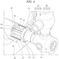
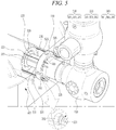
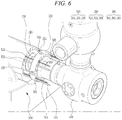
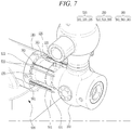
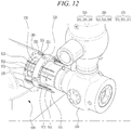
FIGS. 4 to 7 are views sequentially showing a method of assembling the steam turbine according to an embodiment of the present invention; -
FIGS. 8 and 9 are views illustrating a process in which a piston of the steam valve is disposed in the turbine main body; -
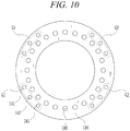
FIG. 10 is a view schematically showing a flange of the steam valve; and -
FIGS. 11 to 14 are views sequentially showing a method of disassembling the steam turbine according to an embodiment of the present invention. - Since embodiments of the present invention can be variously modified in many different forms, reference will now be made in detail to specific embodiments of the present invention. It is to be understood that the present description is not intended to limit the present invention to those specific embodiments and that the present invention is intended to cover not only the specific embodiments but also various alternatives, modifications, equivalents and other embodiments that may be included within the spirit and scope of the present invention as defined by the appended claims.
- The terminology used herein is for the purpose of describing particular embodiments only and is not intended to be limiting. As used herein, the singular forms are intended to include the plural forms as well, unless the context clearly indicates otherwise. It will be further understood that the terms "comprise", "include", "have", etc. when used in this specification, specify the presence of stated features, integers, steps, operations, elements, components, and/or combinations thereof, but do not preclude the presence or addition of one or more other features, integers, steps, operations, elements, components, and/or combinations thereof Hereinafter, a steam turbine according to an embodiment of the present invention will be described with reference to the accompanying drawings.
- Before describing the steam turbine according to this embodiment, a power facility including the steam turbine according to this embodiment will be described. The power facility including the steam turbine according to this embodiment is used in a steam power plant or a nuclear power plant. The power facility may operate a generator using steam that is generated by thermal energy obtained through the combustion of coal, petroleum, or natural gas or through atomic fission in order to produce electric power.
- Hereinafter, a power facility that is applied to a nuclear power plant will be described with reference to
FIG. 1 . However, the power facility including the steam turbine according to this embodiment may also be applicable to a steam power plant, in addition to the nuclear power plant. -
FIG. 1 schematically shows a power facility including a steam turbine according to an embodiment of the present invention. - Referring to
FIG. 1 , the power facility may include anuclear reactor 7, asteam valve 16,steam turbines reheater 18, a generator (G) 20, acondenser 21,water heaters water supply pump 23. - The
nuclear reactor 7 controls a chain reaction of atomic fission in order to generate steam using thermal energy generated during atomic fission. Thenuclear reactor 7 may include a plurality of fuel rods, a control rod, and a cooler. - A
main steam pipe 14 may be connected to thenuclear reactor 7 in order to supply steam that is generated by thenuclear reactor 7 to the high-pressure turbine 17. The steam supplied to themain steam pipe 14 may be supplied to the high-pressure turbine 17 via thesteam valve 16, which is disposed in themain steam pipe 14. Thesteam valve 16 may control the amount of steam to be supplied to the high-pressure turbine 17. - The steam supplied to the high-
pressure turbine 17 is supplied to the low-pressure turbine 19 via the moisture separator andreheater 18. The low-pressure turbine 19 may be connected to thegenerator 20. - The
condenser 21, which condenses steam discharged from the low-pressure turbine 19, may be installed at the outlet of the low-pressure turbine 19. The low-pressure water heater 22, thewater supply pump 23, and the high-pressure water heater 24 may be installed downstream of thecondenser 21. - A
water supply pipe 15 may be connected to the downstream side of thecondenser 21 and extends from thecondenser 21 to thenuclear reactor 7. The low-pressure water heater 22, which heats the water supplied from thecondenser 21, thewater supply pump 23, which pressurizes the water to be supplied to thenuclear reactor 7, and the high-pressure water heater 24, which heats the water to be supplied to thenuclear reactor 7, may be arranged in that order along thewater supply pipe 15. - Hereinafter, the steam turbine, which is used in the power facility, will be described with reference to
FIGS. 2 and3 . -
FIG. 2 illustrates a turbine main body and a steam valve, shown in region A ofFIG. 1 .FIG. 3 shows the state in which connection units corresponding to the turbine main body and steam valve, shown in region B ofFIG. 2 , are coupled to each other. - Referring to
FIGS. 2 and3 , a steam turbine according to an embodiment of the present invention may include a turbinemain body 500 and asteam valve 100 configured to control the amount of steam to be supplied to the turbinemain body 500. A steam supply unit (not shown) supplies steam to the turbinemain body 500, and the supplied steam rotates a turbine unit of the turbinemain body 500. - The steam supply unit may be the
nuclear reactor 7 shown inFIG. 1 . That is, though the present invention is not limited to application of thenuclear reactor 7, the steam supplied to the turbinemain body 500 may be steam generated by thermal energy obtained through atomic fission. Alternatively, the steam supply unit may be a boiler in a steam power plant, such that steam supplied to the turbinemain body 500 is generated by thermal energy obtained through combustion of fossil fuels such as coal, petroleum, or natural gas. - The turbine
main body 500 is a device that rotates a turbine unit using the steam supplied from the steam supply unit in order to generate rotary motion. Meanwhile, thegenerator 20 shown inFIG. 1 may be rotated to generate electricity and is connected to the turbinemain body 500. That is, the turbinemain body 500 shown inFIGS. 2 and3 may be thesteam turbines FIG. 1 . Thus, referring toFIG. 2 ,steam valves main body 500 and the steam supply unit. - The
steam valves main body 500. Specifically, asteam valve main body 500. InFIG. 2 , twosteam valves main body 500, but the present invention is not limited to this configuration, and one or more steam valves may be employed and respectively coupled to the turbinemain body 500. That is, the present embodiment is applicable to a single steam valve, or to plural steam valves individually. - Referring to
FIG. 3 , when thesteam valve 100 is coupled to the turbinemain body 500, afirst connection unit 510 of the turbinemain body 500 and asecond connection unit 120 of thesteam valve 100 are brought into tight contact with each other. More specifically, apiston 130, which is connected to thesecond connection unit 120, comes into tight contact with an inner wall of thefirst connection unit 510 of the turbinemain body 500. Apiston ring 170 may be disposed at an outer circumferential surface of thepiston 130 in order to prevent the leakage of steam. That is, thepiston ring 170 may be interposed between the inner wall of thefirst connection unit 510 and the outer circumferential surface of thepiston 130 in order to prevent the leakage (discharge) of steam being supplied to the turbinemain body 500. - When the
steam valve 100 is coupled to the turbinemain body 500 in the course of assembling or reassembling a steam turbine, a crane is used to move thesteam valve 100, which weighs several hundreds or thousands of kilograms, toward the turbinemain body 500 in a substantially horizontal direction. When thepiston 130 of thesteam valve 100 is inserted into thefirst connection unit 510 of the turbinemain body 500, thepiston ring 170 may collide with the inner wall of thefirst connection unit 510, whereby thepiston ring 170 may be damaged. That is, thepiston ring 170 may be damaged when thesteam valve 100 is horizontally moved toward the turbinemain body 500 while the turbinemain body 500 and thesteam valve 100 are misaligned or otherwise imperfectly aligned with each other. - According to this embodiment, during the assembly of the steam turbine, a plurality of
guide rods 530 provided to the turbinemain body 500 may be inserted into first through-holes 143 (seeFIG. 10 ) formed in aflange 110 of thesteam valve 100 in order to correctly align the turbinemain body 500 and thesteam valve 100 with each other. Specifically, as a valvemain body 150 is moved horizontally using a crane, theguide rods 530 of the turbinemain body 500, which are inserted into the first through-holes 143 formed in theflange 110, may serve to guide the movement of the valvemain body 150. When thepiston 130 is to be inserted into the inner wall of thefirst connection unit 510, therefore, damage to thepiston ring 170 may be prevented. - Meanwhile, according to this embodiment, a plurality of threaded rods 550 (see
FIG. 4 ) may be arranged in the vicinity of theguide rods 530 of the turbinemain body 500. The threadedrods 550 may, together with theguide rods 530, serve to prevent thepiston ring 170 from being damaged during the assembly of the steam turbine. Theguide rods 530 and the threadedrods 550 will be described below in detail. - Hereinafter, a method of assembling a steam turbine according to an embodiment of the present invention will be described with reference to
FIGS. 4 to 7 . Preliminary to describing the method of assembling the steam turbine according to this embodiment, the structure of the steam turbine of the present invention will be described in more detail. - Referring to
FIGS. 4 to 7 , the turbinemain body 500 is a device that rotates a turbine unit disposed therein using the steam supplied from the steam supply unit in order to generate rotary motion. The turbinemain body 500 may include afirst connection unit 510, a plurality ofguide rods 530, and a plurality of threadedrods 550. - The
first connection unit 510 comes into tight contact with thesecond connection unit 120 of thesteam valve 100 when the assembly of the steam turbine is completed by fastening thefirst connection unit 510 and thesecond connection unit 120 to each other. Thefirst connection unit 510 may introduce the steam supplied from the steam supply unit into the turbinemain body 500. - According to this embodiment, the
guide rods 530 may be arranged along the circumference of thefirst connection unit 510. Theguide rods 530 may extend in a first direction. Here, the first direction means a direction that faces thesecond connection unit 120 from thefirst connection unit 510, which is opposite thesecond connection unit 120, inFIG. 4 . That is, theguide rods 530 may extend from thefirst connection unit 510 toward thesecond connection unit 120, when the first and second connection units are positioned for assembly. - The
first connection unit 510 includes an inner circumference and an end surface 511 provided around the inner circumference, so that theguide rods 530 may be fixedly coupled to the end surface 511 of thefirst connection unit 510. Similarly, the plurality of threadedrods 550 extend in the first direction, from the end surface 511, and may be fixedly coupled to thefirst connection unit 510 adjacent to theguide rods 530. - When the
steam valve 100 is coupled to the turbinemain body 500, theguide rods 530 may serve to guide thesecond connection unit 120 of thesteam valve 100 such that thesecond connection unit 120 of thesteam valve 100 can be correctly coupled to thefirst connection unit 510 of the turbinemain body 500. When thesecond connection unit 120 is moved toward thefirst connection unit 510 by the crane (not shown), theguide rods 530 are inserted into the first through-holes 143 (seeFIG. 10 ) formed in theflange 110 of thesecond connection unit 120, whereby thesecond connection unit 120 is moved along a predetermined route and is then coupled to thefirst connection unit 510. When thepiston ring 170 of thesteam valve 100 is inserted into the inner wall of thefirst connection unit 510, therefore, thepiston ring 170 may be prevented from being damaged. - The
guide rods 530 may be arranged symmetrically along the circumference of thefirst connection unit 510. That is, theguide rods 530 are arranged symmetrically around the inner circumference of thefirst connection unit 510. For example, in the case in which fourguide rods 530 are arranged along the circumference of thefirst connection unit 510, aguide rod 535 may be disposed at the circumference of thefirst connection unit 510 in the direction of 1 o'clock, a guide rod (not shown) may be disposed at the circumference of thefirst connection unit 510 in the direction of 4 o'clock, aguide rod 531 may be disposed at the circumference of thefirst connection unit 510 in the direction of 7 o'clock, and aguide rod 533 may be disposed at the circumference of thefirst connection unit 510 in the direction of 10 o'clock. Here, when thefirst connection unit 510 of the turbinemain body 500 is viewed from thesteam valve 100, the peak is defined as 12 o'clock, and the nadir is defined as 6 o'clock. - Each of the
guide rods 530 may be formed to have a cylindrical shape. In particular, the basic shape of each of the guide rods is a right circular cylinder, such that the side surface of each of theguide rods 530 may form a straight line. That is, the outer circumferential surface of each of theguide rods 530 may be flat over its full length. Consequently, each of theguide rods 530 may be easily pass through a corresponding one of the first through-holes 143 (seeFIG. 10 ) formed in theflange 110. Theflange 110 may be integrally formed with thesecond connection unit 120 to be disposed around thesecond connection unit 120 so as to face the end surface 511 of thefirst connection unit 510. - In addition, a distal end of each of the
guide rods 530 may be formed to have a tapered surface, such that the sectional area of each distal end gradually decreases from the turbinemain body 500 toward thesteam valve 100. For example, the distal end of each of theguide rods 530 may be formed to have a cone shape including a pointed tip. As shown inFIG. 4 , therefore, each of theguide rods 530 may be easily inserted into a corresponding one of the first through-holes 143 (seeFIG. 10 ) formed in theflange 110. - Meanwhile, according to this embodiment, the threaded
rods 550 may be arranged along the circumference of thefirst connection unit 510. The threadedrods 550 may be fixedly coupled to thefirst connection unit 510. That is, the threadedrods 550 are fixed so as not to be rotated or moved when the turbinemain body 500 and thesteam valve 100 are assembled. - The threaded
rods 550 may be arranged so as to be adjacent to theguide rods 530. For example, a threadedrod 551 may be disposed so as to be adjacent to theguide rod 531, a threadedrod 553 may be disposed so as to be adjacent to theguide rod 533, and a threadedrod 555 may be disposed so as to be adjacent to theguide rod 535. The threadedrods 550 may extend in the first direction in the same manner as theguide rods 530. - Each of the threaded
rods 550 may be formed to have a cylindrical shape. A screw thread may be formed in the outer circumferential surface of each of the threadedrods 550. When the turbinemain body 500 and thesteam valve 100 are assembled, the threadedrods 550 are inserted through second through-holes 141 (seeFIG. 10 ) formed in theflange 110. The inner diameter of each of the second through-holes 141 (seeFIG. 10 ) may be greater than the outer diameter of a corresponding one of the threadedrods 550. When the threadedrods 550 are inserted through the second through-holes 141 (seeFIG. 10 ), uneven friction between the outer circumferential surface of each of the threadedrods 550 and the inner circumferential surface of a corresponding one of the second through-holes 141 (seeFIG. 10 ) is prevented. -
Nuts 560 may be fitted onto the threadedrods 550. Anut 561 may be fitted onto the threadedrod 551, anut 563 may be fitted onto the threadedrod 553, and anut 565 may be fitted onto the threadedrod 555. - The
flange 110 may be moved toward thefirst connection unit 510 by rotating the nuts 560. According to this embodiment, thesecond connection unit 120 may be correctly moved toward thefirst connection unit 510 by simultaneously and equally rotating the nuts 560 fitted onto the threadedrods 550. The movement of thefirst connection unit 510 toward thesecond connection unit 120, and in turn thesteam valve 100 toward the turbinemain body 500, follows a path in opposition to the first direction of the extending of theguide rods 530 and threadedrods 550. At this time, each of thenuts 560 may be moved an equal distance toward thefirst connection unit 510 by simultaneously and equally rotating the nuts 560. After thenuts 560 are rotated to draw thesteam valve 100 tightly against the turbinemain body 500, the first connection unit and the second connection unit are fastened to each other using separate coupling means (not shown). - The process of assembling the steam turbine according to this embodiment will now be described with reference to
FIGS. 4 to 7 . - Referring to
FIG. 4 , thesteam valve 100 is moved first toward the turbinemain body 500 such that each of theguide rods 530 can be inserted into a corresponding one of the first through-holes 143 (seeFIG. 10 ) formed in theflange 110 of thesteam valve 100. At this time, each of theguide rods 530 can be easily inserted into a corresponding one of the first through-holes 143 (seeFIG. 10 ), since the distal end of each of theguide rods 530 is tapered. - As shown in
FIG. 5 , thesteam valve 100 is further moved toward the turbinemain body 500 such that each of the threadedrods 550 can be inserted through a corresponding one of the second through-holes 141 (seeFIG. 10 ) formed in theflange 110. Subsequently, thenuts 560 are fitted onto nut-receiving ends of the threadedrods 550 after the threadedrods 550 have been sufficiently inserted through the second through-holes 141 (seeFIG. 10 ) to expose one or more of the nut-receiving ends. - Subsequently, the
nuts 560 fitted onto the threadedrods 550 are rotated simultaneously and equally such that thenuts 560 are moved toward the turbinemain body 500, as shown inFIGS. 6 and7 . As a result, thesteam valve 100 may be moved toward the turbinemain body 500. Thesteam valve 100 can be correctly moved toward the turbinemain body 500 along theguide rods 530 by simultaneously and equally rotating the nuts 560 fitted onto the threadedrods 550. Because thesteam valve 100 is moved correctly, thepiston 130 of thesteam valve 100 may be moved without uneven friction between thepiston 130 of thesteam valve 100 and the inner wall of thefirst connection unit 510. - That is, in the method of assembling the steam turbine according to this embodiment, the
piston 130 is moved correctly when thesteam valve 100 is moved to the turbinemain body 500 during the assembly of the steam turbine, as shown inFIGS. 8 and 9 . As a result, it is possible to prevent thepiston ring 170 from being damaged due to uneven friction between thepiston ring 170 and the inner wall of thefirst connection unit 510. - Meanwhile, referring to
FIG. 10 , the first through-holes 143 and the second through-holes 141 may be formed in theflange 110. As described above, theguide rods 530 may be inserted through the first through-holes 143 formed in theflange 110, and the threadedrods 550 may be inserted through the second through-holes 141 formed in theflange 110. The second through-holes 141 may be formed so as to be adjacent to the first through-holes 143 based on the positional relationship between theguide rods 530 and the threadedrods 550. - In addition, the first through-
holes 143 and the second through-holes 141 may be formed in theflange 110 in a symmetrical fashion. For example, one of the first through-holes 143 and one of the second through-holes 141 may be disposed in a region G1, and another of the first through-holes 143 and another of the second through-holes 141 may be disposed in another region G2. - In addition, yet another of the first through-
holes 143 and yet another of the second through-holes 141 may be disposed in yet another region G3, and still yet another of the first through-holes 143 and still yet another of the second through-holes 141 may be disposed in still yet another region G4. At this time, the regions G1, G2, G3, and G4 may be disposed in a symmetrical fashion, as shown inFIG. 10 . - Meanwhile, a third through-
hole 145 may be formed in each of the regions G1, G2, G3, and G4 so as to be adjacent to a corresponding one of the first through-holes 143 and a corresponding one of the second through-holes 141. A plurality of screw jacks 570 (seeFIG. 11 ) may be inserted through the third through-holes 145, a description of which will follow. The screw jacks 570 may be used to separate thesteam valve 100 from the turbinemain body 500. The screw jacks 570 will be described below in detail. - Hereinafter, a method of disassembling a steam turbine according to an embodiment of the present invention will be described with reference to the sequential views of
FIGS. 11 to 14 . - When it is necessary to maintain and repair the steam turbine, the
steam valve 100 is separated from the turbinemain body 500 in order to disassemble the steam turbine. First, as shown inFIG. 11 , each of thescrew jacks 570 is inserted into a corresponding one of the third through-holes 145 (seeFIG. 10 ) formed in theflange 110. Each of thescrew jacks 570 is a bar-shaped member having a screw thread formed in the outer circumferential surface thereof Each of thescrew jacks 570 may be a well-known device that is capable of moving an object through rotary motion thereof. According to this embodiment, each of the third through-holes 145 (seeFIG. 10 ) formed in theflange 110 is provided in the inner circumferential surface thereof with a screw thread, which is engaged with the screw thread formed in a corresponding one of the screw jacks 570. Thus, thescrew jacks 570 are applied around theflange 110 in a symmetrical fashion corresponding to the arrangement of theguide rods 530 or the threadedrods 550, and are actuated such that thesteam valve 100 is separated from the turbinemain body 500 in the first direction. - Subsequently, as shown in
FIGS. 12 to 14 , thescrew jacks 570 are simultaneously rotated in one direction. At this time, thescrew jacks 570 are moved in the same direction as the direction in which theguide rods 530 and the threadedrods 550 extend. - As a result, the
second connection unit 120 becomes gradually spaced apart from thefirst connection unit 510, in a manner reverse to the process of assembling the steam turbine. When thescrew jacks 570 are rotated simultaneously and equally, thesecond connection unit 120 may be correctly moved from thefirst connection unit 510. - During the disassembly of the steam turbine, the
piston 130 is correctly moved by thescrew jacks 570, making it possible to prevent thepiston ring 170 from being damaged due to uneven friction between thepiston ring 170 and the inner wall of thefirst connection unit 510, in the same manner as in the process of assembling the steam turbine. - As is apparent from the above description, in the steam turbine and the method of assembling and disassembling the same, it is possible to prevent components constituting the steam valve from being damaged during the assembly or disassembly of the steam turbine.
- Although embodiments have been described with reference to a number of illustrative embodiments thereof, those skilled in the art will appreciate that the present invention can be variously modified and altered through the addition, change, or deletion of components without departing from the idea of the invention as disclosed in the accompanying claims and that such modifications and alterations fall within the scope of rights of the present invention.
- Although the preferred embodiments of the present invention have been disclosed for illustrative purposes, those skilled in the art will appreciate that various modifications, additions and substitutions are possible, without departing from the scope and spirit of the invention as disclosed in the accompanying claims.
Claims (15)
- A steam turbine comprising a turbine main body(500) supplied with steam from a steam supply unit and a steam valve(100, 300) for controlling an amount of steam to be supplied from the steam supply unit to the turbine main body(500),
wherein the turbine main body(500) comprises:a first connection unit(510); anda plurality of guide rods(530) extending from the first connection unit(510) in a first direction, andwherein the steam valve(100, 300) comprises:a second connection unit(120) configured to be coupled to the first connection unit(510); anda flange(110) disposed around the second connection unit(120) and configured to receive the guide rods(530) through a plurality of first through-holes respectively formed in the flange(110). - The steam turbine according to claim 1, wherein the first connection unit(510) includes an inner circumference and an end surface provided around the inner circumference.
- The steam turbine according to claim 1 or claim 2, wherein the guide rods(530) are arranged symmetrically around the inner circumference of the first connection unit(510).
- The steam turbine according to one of the claim 1 to the claim 3, wherein the guide rods(530) are fixedly coupled to the end surface of the first connection unit(510).
- The steam turbine according to one of the claim 1 to the claim 4, wherein the turbine main body(500) further comprises a plurality of threaded rods extending in the first direction,
and wherein the threaded rods are fixedly coupled to the first connection unit(510) adjacent to the guide rods(530). - The steam turbine according to one of the claim 1 to the claim 5, wherein the flange(110) is further configured to receive the threaded rods through a plurality of second through-holes respectively formed in the flange(110) adjacent to the first through-holes.
- The steam turbine according to one of the claim 1 to the claim 6, wherein each of the threaded rods has an outer diameter smaller than an inner diameter of a corresponding one of the second through-holes, and
wherein the turbine main body(500) further comprises a plurality of nuts respectively fitted onto the threaded rods for moving the steam valve(100, 300) toward the turbine main body(500). - The steam turbine according to one of the claim 1 to the claim 7, wherein each of the guide rods(530) includes a distal end formed to have a tapered surface, or wherein each of the guide rods(530) is formed to have a cylindrical shape and a flat side surface.
- The steam turbine according to one of the claim 1 to the claim 8, wherein the flange(110) is further configured to receive a plurality of screw jacks through a plurality of third through-holes respectively formed in the flange(110) adjacent to the first through-holes.
- A method of assembling a steam turbine, the method comprising:preparing a turbine main body(500) comprising a turbine unit configured to be rotated by a supply of steam, a first connection unit(510) configured to receive the supply of steam, a plurality of guide rods(530) extending from the first connection unit(510) in a first direction, and a plurality of threaded rods disposed so as to be adjacent to the guide rods(530), the threaded rods extending in the first direction;preparing a steam valve(100, 300) configured to control an amount of steam to be supplied into the turbine main body(500), the steam valve(100, 300) comprising a second connection unit(120) disposed so as to face the first connection unit(510), and a flange(110) disposed around the second connection unit(120) and configured to receive the guide rods(530) through a plurality of first through-holes respectively formed in the flange(110) and to receive the threaded rods through a plurality of second through-holes respectively formed in the flange(110) adjacent to the first through-holes;moving the steam valve(100, 300) toward the turbine main body(500) in opposition to the first direction such that a distal end of each of the guide rods(530) is inserted into a corresponding one of the first through-holes;further moving the steam valve(100, 300) toward the turbine main body(500) after the guide rod insertion, such that a nut-receiving end of each of the threaded rods is inserted through a corresponding one of the second through-holes;fitting each of a plurality of nuts onto the nut-receiving end of a corresponding one of the threaded rods, after the threaded rod insertion; androtating the nuts such that the first connection unit(510) and the second connection unit(120) come into tight contact with each other.
- The method according to claim 10, wherein the rotating the nuts comprises simultaneously moving the nuts toward the turbine main body(500).
- The method according to claim 10 or claim 11, wherein the simultaneously moving the nuts comprises moving each of the nuts an equal distance in opposition to the first direction.
- The method according to one of the claim 10 to the claim 12, wherein the first connection unit(510) includes an inner circumference and an end surface provided around the inner circumference, and the guide rods(530) are arranged symmetrically around the inner circumference of the first connection unit(510).
- The method according to one of the claim 10 to the claim 13, wherein the first connection unit(510) includes an inner circumference and an end surface provided around the inner circumference, and the guide rods(530) are fixedly coupled to the end surface of the first connection unit(510).
- The method according to one of the claim 10 to the claim 14, wherein the first connection unit(510) includes an inner circumference and an end surface provided around the inner circumference, and the threaded rods are fixedly coupled to the end surface of the first connection unit(510) adjacent to the guide rods(530), and
wherein each of the threaded rods has an outer diameter smaller than an inner diameter of a corresponding one of the second through-holes.
Applications Claiming Priority (1)
| Application Number | Priority Date | Filing Date | Title |
|---|---|---|---|
| KR1020170063415A KR101925214B1 (en) | 2017-05-23 | 2017-05-23 | Steam turbine and method for assembling and method for disassembling the same |
Publications (3)
| Publication Number | Publication Date |
|---|---|
| EP3406971A1 true EP3406971A1 (en) | 2018-11-28 |
| EP3406971B1 EP3406971B1 (en) | 2022-08-31 |
| EP3406971B8 EP3406971B8 (en) | 2022-11-02 |
Family
ID=62002069
Family Applications (1)
| Application Number | Title | Priority Date | Filing Date |
|---|---|---|---|
| EP18167458.1A Active EP3406971B8 (en) | 2017-05-23 | 2018-04-16 | Steam turbine and method of assembling the same |
Country Status (3)
| Country | Link |
|---|---|
| US (1) | US10724394B2 (en) |
| EP (1) | EP3406971B8 (en) |
| KR (1) | KR101925214B1 (en) |
Citations (7)
| Publication number | Priority date | Publication date | Assignee | Title |
|---|---|---|---|---|
| US3730537A (en) * | 1969-05-15 | 1973-05-01 | Brown & Root | Method and apparatus utilizing handled seal for submergible coupling |
| US3768776A (en) * | 1972-07-24 | 1973-10-30 | Carrier Corp | Steam turbine governor valve actuating mechanism |
| WO1985003986A1 (en) * | 1984-03-05 | 1985-09-12 | Dresser Industries, Inc. | Clamping assembly |
| US6099246A (en) * | 1998-01-27 | 2000-08-08 | Siemens Aktiengesellschaft | Admission section of a turbine casing |
| US20120042492A1 (en) * | 2010-08-20 | 2012-02-23 | Merrill Peter K | Alignment Mechanism for Assembly of a Diffuser Inside a Pressure Reducing and Conditioning Valve |
| WO2013181704A1 (en) * | 2012-06-05 | 2013-12-12 | Osprey Subsea Technical Solutions (Osts) Pty Ltd | Flange catching, aligning and closing tool |
| CN102554869B (en) * | 2010-12-15 | 2014-06-11 | 珠海格力电器股份有限公司 | Tooling for fast fastening, dismantling or adjusting peripheral bolts and method of use thereof |
Family Cites Families (18)
| Publication number | Priority date | Publication date | Assignee | Title |
|---|---|---|---|---|
| US4052045A (en) * | 1976-07-29 | 1977-10-04 | Billy Joe Shaddix | Alignment of flanges |
| US4395885A (en) * | 1981-10-08 | 1983-08-02 | Cozby Enterprises, Inc. | Unitary steam engine |
| US4842244A (en) * | 1987-11-10 | 1989-06-27 | Niagara Mohawk Power Corporation | Valve control system for power generating plants |
| CH677820A5 (en) * | 1988-12-23 | 1991-06-28 | Asea Brown Boveri | |
| US5882511A (en) * | 1996-10-30 | 1999-03-16 | Fil-Tech Corporation | Filter apparatus with coupling and latch mechanism |
| US20030150493A1 (en) * | 2002-02-14 | 2003-08-14 | Glover Walter S. | In-line differential pressure controller |
| US7421783B2 (en) * | 2004-11-12 | 2008-09-09 | General Electric Company | Methods of installing centerline supported carriers for steam turbines |
| JP2007170630A (en) | 2005-12-26 | 2007-07-05 | Tabuchi Corp | Check valve mounting structure |
| EP1816357A1 (en) * | 2006-02-02 | 2007-08-08 | Siemens Aktiengesellschaft | Screw for a thermally charged environment |
| KR200444248Y1 (en) | 2007-10-10 | 2009-04-22 | 두산중공업 주식회사 | Control Valve for Turbine Main Steam in Power Plant |
| WO2009123299A1 (en) * | 2008-04-03 | 2009-10-08 | Mitsubishi Heavy Industries, Ltd. | Connecting structure of double tube and assembling or disassembling method of double tube |
| US8684677B1 (en) * | 2009-07-02 | 2014-04-01 | Cummins Turbo Technologies Limited | Turbocharger |
| US20110131781A1 (en) * | 2009-12-31 | 2011-06-09 | Alistair Jeffrey Smith | Systems and methods for assembling a bore repair assembly for use in a wind turbine |
| EP2937520B1 (en) | 2012-12-21 | 2017-09-20 | Mitsubishi Hitachi Power Systems, Ltd. | Steam valve and steam turbine |
| US9267615B1 (en) * | 2013-10-30 | 2016-02-23 | Cortec, L.L.C. | Method and apparatus for removing, repairing, refurbishing, replacing, and/or installing valve between two fixed spool pieces |
| KR101624054B1 (en) * | 2014-11-21 | 2016-05-24 | 두산중공업 주식회사 | Gas turbine with a plurality of tie rods and assembling method thoreof |
| KR101657698B1 (en) | 2015-04-27 | 2016-09-19 | 한국해양대학교 산학협력단 | Apparatus For Underwater Visible Lighting Equipped With Duplex Communication System |
| WO2017023303A1 (en) * | 2015-08-05 | 2017-02-09 | Stren Microlift Technology, Llc | Hydraulic pumping system for use with a subterranean well |
-
2017
- 2017-05-23 KR KR1020170063415A patent/KR101925214B1/en active Active
-
2018
- 2018-03-26 US US15/935,057 patent/US10724394B2/en active Active
- 2018-04-16 EP EP18167458.1A patent/EP3406971B8/en active Active
Patent Citations (7)
| Publication number | Priority date | Publication date | Assignee | Title |
|---|---|---|---|---|
| US3730537A (en) * | 1969-05-15 | 1973-05-01 | Brown & Root | Method and apparatus utilizing handled seal for submergible coupling |
| US3768776A (en) * | 1972-07-24 | 1973-10-30 | Carrier Corp | Steam turbine governor valve actuating mechanism |
| WO1985003986A1 (en) * | 1984-03-05 | 1985-09-12 | Dresser Industries, Inc. | Clamping assembly |
| US6099246A (en) * | 1998-01-27 | 2000-08-08 | Siemens Aktiengesellschaft | Admission section of a turbine casing |
| US20120042492A1 (en) * | 2010-08-20 | 2012-02-23 | Merrill Peter K | Alignment Mechanism for Assembly of a Diffuser Inside a Pressure Reducing and Conditioning Valve |
| CN102554869B (en) * | 2010-12-15 | 2014-06-11 | 珠海格力电器股份有限公司 | Tooling for fast fastening, dismantling or adjusting peripheral bolts and method of use thereof |
| WO2013181704A1 (en) * | 2012-06-05 | 2013-12-12 | Osprey Subsea Technical Solutions (Osts) Pty Ltd | Flange catching, aligning and closing tool |
Also Published As
| Publication number | Publication date |
|---|---|
| EP3406971B8 (en) | 2022-11-02 |
| US10724394B2 (en) | 2020-07-28 |
| EP3406971B1 (en) | 2022-08-31 |
| KR20180128200A (en) | 2018-12-03 |
| US20180340443A1 (en) | 2018-11-29 |
| KR101925214B1 (en) | 2018-12-04 |
Similar Documents
| Publication | Publication Date | Title |
|---|---|---|
| US8978388B2 (en) | Load member for transition duct in turbine system | |
| US5526386A (en) | Method and apparatus for steam mixing a nuclear fueled electricity generation system | |
| CN101999056B (en) | Connecting structure of double tube and assembling or disassembling method of double tube | |
| WO1995032509A9 (en) | Method and apparatus for improving the performance and steam mixing capabilities of a nuclear power electrical generation system | |
| EP3327348A1 (en) | Pipe reinforcement device and pipe reinforcement method | |
| JP2013170814A (en) | Combustion liner guide stopper and method for assembling combustor | |
| US10724394B2 (en) | Steam turbine and method of assembling and disassembling the same | |
| US8650852B2 (en) | Support assembly for transition duct in turbine system | |
| US7203263B2 (en) | Core spray apparatus and method for installing the same | |
| JP7536513B2 (en) | Cross-fire tube installation/removal method and device | |
| EP2543824B1 (en) | Support assembly for a turbine system and corresponding turbine system | |
| EP2568143A2 (en) | Piping assembly and method for connecting inner and outer shell in turbine system | |
| JP7571117B2 (en) | Axial retention assembly for a combustor component of a gas turbine engine - Patents.com | |
| CN214366251U (en) | Water-attack-prevention steam immersion jet nozzle heat exchange system | |
| US20090060110A1 (en) | Device and method for shutting off an orifice of a bundle wrapper of a steam generator of a pressurized-water nuclear reactor | |
| EP3255345A1 (en) | Installation tool and system for assembling a gas turbine combustor | |
| US8677585B2 (en) | Alignment mechanism for assembly of a diffuser inside a pressure reducing and conditioning valve | |
| KR20160115835A (en) | Integrated dual fuel delivery system | |
| CN102933899A (en) | Device for producing fixture units for steam generator pipes | |
| EP3221642B1 (en) | Lance injector for injecting fuel into a combustion chamber of a gas turbine | |
| EP3318733A1 (en) | Feedwater bypass system for a desuperheater | |
| RU2810870C2 (en) | Axial retaining unit for gas turbine engine combustion chamber components | |
| KR101810893B1 (en) | Maintenace method of in hydraulic actuator for power plant and maintenance method used in it | |
| CN116357476A (en) | A solid attitude control engine capable of multiple starts | |
| US20130067982A1 (en) | Apparatus for producing inserts for steam generator tubes |
Legal Events
| Date | Code | Title | Description |
|---|---|---|---|
| PUAI | Public reference made under article 153(3) epc to a published international application that has entered the european phase |
Free format text: ORIGINAL CODE: 0009012 |
|
| STAA | Information on the status of an ep patent application or granted ep patent |
Free format text: STATUS: REQUEST FOR EXAMINATION WAS MADE |
|
| 17P | Request for examination filed |
Effective date: 20180416 |
|
| AK | Designated contracting states |
Kind code of ref document: A1 Designated state(s): AL AT BE BG CH CY CZ DE DK EE ES FI FR GB GR HR HU IE IS IT LI LT LU LV MC MK MT NL NO PL PT RO RS SE SI SK SM TR |
|
| AX | Request for extension of the european patent |
Extension state: BA ME |
|
| RBV | Designated contracting states (corrected) |
Designated state(s): AL AT BE BG CH CY CZ DE DK EE ES FI FR GB GR HR HU IE IS IT LI LT LU LV MC MK MT NL NO PL PT RO RS SE SI SK SM TR |
|
| STAA | Information on the status of an ep patent application or granted ep patent |
Free format text: STATUS: EXAMINATION IS IN PROGRESS |
|
| 17Q | First examination report despatched |
Effective date: 20210622 |
|
| GRAP | Despatch of communication of intention to grant a patent |
Free format text: ORIGINAL CODE: EPIDOSNIGR1 |
|
| STAA | Information on the status of an ep patent application or granted ep patent |
Free format text: STATUS: GRANT OF PATENT IS INTENDED |
|
| INTG | Intention to grant announced |
Effective date: 20220524 |
|
| GRAS | Grant fee paid |
Free format text: ORIGINAL CODE: EPIDOSNIGR3 |
|
| GRAA | (expected) grant |
Free format text: ORIGINAL CODE: 0009210 |
|
| STAA | Information on the status of an ep patent application or granted ep patent |
Free format text: STATUS: THE PATENT HAS BEEN GRANTED |
|
| AK | Designated contracting states |
Kind code of ref document: B1 Designated state(s): AL AT BE BG CH CY CZ DE DK EE ES FI FR GB GR HR HU IE IS IT LI LT LU LV MC MK MT NL NO PL PT RO RS SE SI SK SM TR |
|
| REG | Reference to a national code |
Ref country code: CH Ref legal event code: EP Ref country code: GB Ref legal event code: FG4D |
|
| REG | Reference to a national code |
Ref country code: DE Ref legal event code: R081 Ref document number: 602018039905 Country of ref document: DE Owner name: DOOSAN ENERBILITY CO., LTD., CHANGWON-SI, KR Free format text: FORMER OWNER: DOOSAN HEAVY INDUSTRIES & CONSTRUCTION CO., LTD., CHANGWON-SI, GYEONGSANGNAM-DO, KR |
|
| REG | Reference to a national code |
Ref country code: AT Ref legal event code: REF Ref document number: 1515553 Country of ref document: AT Kind code of ref document: T Effective date: 20220915 |
|
| REG | Reference to a national code |
Ref country code: DE Ref legal event code: R096 Ref document number: 602018039905 Country of ref document: DE |
|
| REG | Reference to a national code |
Ref country code: IE Ref legal event code: FG4D |
|
| RAP4 | Party data changed (patent owner data changed or rights of a patent transferred) |
Owner name: DOOSAN ENERBILITY CO., LTD. |
|
| REG | Reference to a national code |
Ref country code: CH Ref legal event code: PK Free format text: BERICHTIGUNG B8 |
|
| REG | Reference to a national code |
Ref country code: LT Ref legal event code: MG9D |
|
| REG | Reference to a national code |
Ref country code: NL Ref legal event code: MP Effective date: 20220831 |
|
| PG25 | Lapsed in a contracting state [announced via postgrant information from national office to epo] |
Ref country code: SE Free format text: LAPSE BECAUSE OF FAILURE TO SUBMIT A TRANSLATION OF THE DESCRIPTION OR TO PAY THE FEE WITHIN THE PRESCRIBED TIME-LIMIT Effective date: 20220831 Ref country code: RS Free format text: LAPSE BECAUSE OF FAILURE TO SUBMIT A TRANSLATION OF THE DESCRIPTION OR TO PAY THE FEE WITHIN THE PRESCRIBED TIME-LIMIT Effective date: 20220831 Ref country code: NO Free format text: LAPSE BECAUSE OF FAILURE TO SUBMIT A TRANSLATION OF THE DESCRIPTION OR TO PAY THE FEE WITHIN THE PRESCRIBED TIME-LIMIT Effective date: 20221130 Ref country code: LV Free format text: LAPSE BECAUSE OF FAILURE TO SUBMIT A TRANSLATION OF THE DESCRIPTION OR TO PAY THE FEE WITHIN THE PRESCRIBED TIME-LIMIT Effective date: 20220831 Ref country code: LT Free format text: LAPSE BECAUSE OF FAILURE TO SUBMIT A TRANSLATION OF THE DESCRIPTION OR TO PAY THE FEE WITHIN THE PRESCRIBED TIME-LIMIT Effective date: 20220831 Ref country code: FI Free format text: LAPSE BECAUSE OF FAILURE TO SUBMIT A TRANSLATION OF THE DESCRIPTION OR TO PAY THE FEE WITHIN THE PRESCRIBED TIME-LIMIT Effective date: 20220831 |
|
| REG | Reference to a national code |
Ref country code: AT Ref legal event code: MK05 Ref document number: 1515553 Country of ref document: AT Kind code of ref document: T Effective date: 20220831 |
|
| PG25 | Lapsed in a contracting state [announced via postgrant information from national office to epo] |
Ref country code: PL Free format text: LAPSE BECAUSE OF FAILURE TO SUBMIT A TRANSLATION OF THE DESCRIPTION OR TO PAY THE FEE WITHIN THE PRESCRIBED TIME-LIMIT Effective date: 20220831 Ref country code: IS Free format text: LAPSE BECAUSE OF FAILURE TO SUBMIT A TRANSLATION OF THE DESCRIPTION OR TO PAY THE FEE WITHIN THE PRESCRIBED TIME-LIMIT Effective date: 20221231 Ref country code: HR Free format text: LAPSE BECAUSE OF FAILURE TO SUBMIT A TRANSLATION OF THE DESCRIPTION OR TO PAY THE FEE WITHIN THE PRESCRIBED TIME-LIMIT Effective date: 20220831 Ref country code: GR Free format text: LAPSE BECAUSE OF FAILURE TO SUBMIT A TRANSLATION OF THE DESCRIPTION OR TO PAY THE FEE WITHIN THE PRESCRIBED TIME-LIMIT Effective date: 20221201 |
|
| PG25 | Lapsed in a contracting state [announced via postgrant information from national office to epo] |
Ref country code: SM Free format text: LAPSE BECAUSE OF FAILURE TO SUBMIT A TRANSLATION OF THE DESCRIPTION OR TO PAY THE FEE WITHIN THE PRESCRIBED TIME-LIMIT Effective date: 20220831 Ref country code: RO Free format text: LAPSE BECAUSE OF FAILURE TO SUBMIT A TRANSLATION OF THE DESCRIPTION OR TO PAY THE FEE WITHIN THE PRESCRIBED TIME-LIMIT Effective date: 20220831 Ref country code: PT Free format text: LAPSE BECAUSE OF FAILURE TO SUBMIT A TRANSLATION OF THE DESCRIPTION OR TO PAY THE FEE WITHIN THE PRESCRIBED TIME-LIMIT Effective date: 20230102 Ref country code: ES Free format text: LAPSE BECAUSE OF FAILURE TO SUBMIT A TRANSLATION OF THE DESCRIPTION OR TO PAY THE FEE WITHIN THE PRESCRIBED TIME-LIMIT Effective date: 20220831 Ref country code: DK Free format text: LAPSE BECAUSE OF FAILURE TO SUBMIT A TRANSLATION OF THE DESCRIPTION OR TO PAY THE FEE WITHIN THE PRESCRIBED TIME-LIMIT Effective date: 20220831 Ref country code: AT Free format text: LAPSE BECAUSE OF FAILURE TO SUBMIT A TRANSLATION OF THE DESCRIPTION OR TO PAY THE FEE WITHIN THE PRESCRIBED TIME-LIMIT Effective date: 20220831 |
|
| PG25 | Lapsed in a contracting state [announced via postgrant information from national office to epo] |
Ref country code: SK Free format text: LAPSE BECAUSE OF FAILURE TO SUBMIT A TRANSLATION OF THE DESCRIPTION OR TO PAY THE FEE WITHIN THE PRESCRIBED TIME-LIMIT Effective date: 20220831 Ref country code: EE Free format text: LAPSE BECAUSE OF FAILURE TO SUBMIT A TRANSLATION OF THE DESCRIPTION OR TO PAY THE FEE WITHIN THE PRESCRIBED TIME-LIMIT Effective date: 20220831 |
|
| REG | Reference to a national code |
Ref country code: DE Ref legal event code: R097 Ref document number: 602018039905 Country of ref document: DE |
|
| PG25 | Lapsed in a contracting state [announced via postgrant information from national office to epo] |
Ref country code: NL Free format text: LAPSE BECAUSE OF FAILURE TO SUBMIT A TRANSLATION OF THE DESCRIPTION OR TO PAY THE FEE WITHIN THE PRESCRIBED TIME-LIMIT Effective date: 20220831 Ref country code: AL Free format text: LAPSE BECAUSE OF FAILURE TO SUBMIT A TRANSLATION OF THE DESCRIPTION OR TO PAY THE FEE WITHIN THE PRESCRIBED TIME-LIMIT Effective date: 20220831 |
|
| PLBE | No opposition filed within time limit |
Free format text: ORIGINAL CODE: 0009261 |
|
| STAA | Information on the status of an ep patent application or granted ep patent |
Free format text: STATUS: NO OPPOSITION FILED WITHIN TIME LIMIT |
|
| 26N | No opposition filed |
Effective date: 20230601 |
|
| PG25 | Lapsed in a contracting state [announced via postgrant information from national office to epo] |
Ref country code: SI Free format text: LAPSE BECAUSE OF FAILURE TO SUBMIT A TRANSLATION OF THE DESCRIPTION OR TO PAY THE FEE WITHIN THE PRESCRIBED TIME-LIMIT Effective date: 20220831 |
|
| REG | Reference to a national code |
Ref country code: CH Ref legal event code: PL |
|
| GBPC | Gb: european patent ceased through non-payment of renewal fee |
Effective date: 20230416 |
|
| PG25 | Lapsed in a contracting state [announced via postgrant information from national office to epo] |
Ref country code: LU Free format text: LAPSE BECAUSE OF NON-PAYMENT OF DUE FEES Effective date: 20230416 |
|
| REG | Reference to a national code |
Ref country code: BE Ref legal event code: MM Effective date: 20230430 |
|
| PG25 | Lapsed in a contracting state [announced via postgrant information from national office to epo] |
Ref country code: MC Free format text: LAPSE BECAUSE OF FAILURE TO SUBMIT A TRANSLATION OF THE DESCRIPTION OR TO PAY THE FEE WITHIN THE PRESCRIBED TIME-LIMIT Effective date: 20220831 |
|
| PG25 | Lapsed in a contracting state [announced via postgrant information from national office to epo] |
Ref country code: GB Free format text: LAPSE BECAUSE OF NON-PAYMENT OF DUE FEES Effective date: 20230416 |
|
| PG25 | Lapsed in a contracting state [announced via postgrant information from national office to epo] |
Ref country code: MC Free format text: LAPSE BECAUSE OF FAILURE TO SUBMIT A TRANSLATION OF THE DESCRIPTION OR TO PAY THE FEE WITHIN THE PRESCRIBED TIME-LIMIT Effective date: 20220831 Ref country code: LI Free format text: LAPSE BECAUSE OF NON-PAYMENT OF DUE FEES Effective date: 20230430 Ref country code: GB Free format text: LAPSE BECAUSE OF NON-PAYMENT OF DUE FEES Effective date: 20230416 Ref country code: FR Free format text: LAPSE BECAUSE OF NON-PAYMENT OF DUE FEES Effective date: 20230430 Ref country code: CH Free format text: LAPSE BECAUSE OF NON-PAYMENT OF DUE FEES Effective date: 20230430 |
|
| REG | Reference to a national code |
Ref country code: IE Ref legal event code: MM4A |
|
| PG25 | Lapsed in a contracting state [announced via postgrant information from national office to epo] |
Ref country code: BE Free format text: LAPSE BECAUSE OF NON-PAYMENT OF DUE FEES Effective date: 20230430 |
|
| PG25 | Lapsed in a contracting state [announced via postgrant information from national office to epo] |
Ref country code: IE Free format text: LAPSE BECAUSE OF NON-PAYMENT OF DUE FEES Effective date: 20230416 |
|
| PG25 | Lapsed in a contracting state [announced via postgrant information from national office to epo] |
Ref country code: IE Free format text: LAPSE BECAUSE OF NON-PAYMENT OF DUE FEES Effective date: 20230416 |
|
| PG25 | Lapsed in a contracting state [announced via postgrant information from national office to epo] |
Ref country code: IT Free format text: LAPSE BECAUSE OF FAILURE TO SUBMIT A TRANSLATION OF THE DESCRIPTION OR TO PAY THE FEE WITHIN THE PRESCRIBED TIME-LIMIT Effective date: 20220831 |
|
| PG25 | Lapsed in a contracting state [announced via postgrant information from national office to epo] |
Ref country code: BG Free format text: LAPSE BECAUSE OF FAILURE TO SUBMIT A TRANSLATION OF THE DESCRIPTION OR TO PAY THE FEE WITHIN THE PRESCRIBED TIME-LIMIT Effective date: 20220831 |
|
| PG25 | Lapsed in a contracting state [announced via postgrant information from national office to epo] |
Ref country code: BG Free format text: LAPSE BECAUSE OF FAILURE TO SUBMIT A TRANSLATION OF THE DESCRIPTION OR TO PAY THE FEE WITHIN THE PRESCRIBED TIME-LIMIT Effective date: 20220831 |
|
| PGFP | Annual fee paid to national office [announced via postgrant information from national office to epo] |
Ref country code: DE Payment date: 20250225 Year of fee payment: 8 |
|
| PG25 | Lapsed in a contracting state [announced via postgrant information from national office to epo] |
Ref country code: CY Free format text: LAPSE BECAUSE OF FAILURE TO SUBMIT A TRANSLATION OF THE DESCRIPTION OR TO PAY THE FEE WITHIN THE PRESCRIBED TIME-LIMIT; INVALID AB INITIO Effective date: 20180416 |
|
| PGFP | Annual fee paid to national office [announced via postgrant information from national office to epo] |
Ref country code: CZ Payment date: 20250331 Year of fee payment: 8 |
|
| PG25 | Lapsed in a contracting state [announced via postgrant information from national office to epo] |
Ref country code: HU Free format text: LAPSE BECAUSE OF FAILURE TO SUBMIT A TRANSLATION OF THE DESCRIPTION OR TO PAY THE FEE WITHIN THE PRESCRIBED TIME-LIMIT; INVALID AB INITIO Effective date: 20180416 |
|
| PG25 | Lapsed in a contracting state [announced via postgrant information from national office to epo] |
Ref country code: TR Free format text: LAPSE BECAUSE OF FAILURE TO SUBMIT A TRANSLATION OF THE DESCRIPTION OR TO PAY THE FEE WITHIN THE PRESCRIBED TIME-LIMIT Effective date: 20220831 |