EP3406948A1 - Pneumatic inflation system - Google Patents
Pneumatic inflation system Download PDFInfo
- Publication number
- EP3406948A1 EP3406948A1 EP18174244.6A EP18174244A EP3406948A1 EP 3406948 A1 EP3406948 A1 EP 3406948A1 EP 18174244 A EP18174244 A EP 18174244A EP 3406948 A1 EP3406948 A1 EP 3406948A1
- Authority
- EP
- European Patent Office
- Prior art keywords
- disc
- rupture
- outlet
- inlet
- inflation system
- Prior art date
- Legal status (The legal status is an assumption and is not a legal conclusion. Google has not performed a legal analysis and makes no representation as to the accuracy of the status listed.)
- Granted
Links
Images
Classifications
-
- F—MECHANICAL ENGINEERING; LIGHTING; HEATING; WEAPONS; BLASTING
- F16—ENGINEERING ELEMENTS AND UNITS; GENERAL MEASURES FOR PRODUCING AND MAINTAINING EFFECTIVE FUNCTIONING OF MACHINES OR INSTALLATIONS; THERMAL INSULATION IN GENERAL
- F16K—VALVES; TAPS; COCKS; ACTUATING-FLOATS; DEVICES FOR VENTING OR AERATING
- F16K31/00—Actuating devices; Operating means; Releasing devices
- F16K31/12—Actuating devices; Operating means; Releasing devices actuated by fluid
- F16K31/122—Actuating devices; Operating means; Releasing devices actuated by fluid the fluid acting on a piston
- F16K31/124—Actuating devices; Operating means; Releasing devices actuated by fluid the fluid acting on a piston servo actuated
-
- G—PHYSICS
- G05—CONTROLLING; REGULATING
- G05D—SYSTEMS FOR CONTROLLING OR REGULATING NON-ELECTRIC VARIABLES
- G05D7/00—Control of flow
- G05D7/06—Control of flow characterised by the use of electric means
- G05D7/0617—Control of flow characterised by the use of electric means specially adapted for fluid materials
- G05D7/0629—Control of flow characterised by the use of electric means specially adapted for fluid materials characterised by the type of regulator means
- G05D7/0676—Control of flow characterised by the use of electric means specially adapted for fluid materials characterised by the type of regulator means by action on flow sources
-
- B—PERFORMING OPERATIONS; TRANSPORTING
- B64—AIRCRAFT; AVIATION; COSMONAUTICS
- B64D—EQUIPMENT FOR FITTING IN OR TO AIRCRAFT; FLIGHT SUITS; PARACHUTES; ARRANGEMENT OR MOUNTING OF POWER PLANTS OR PROPULSION TRANSMISSIONS IN AIRCRAFT
- B64D25/00—Emergency apparatus or devices, not otherwise provided for
- B64D25/08—Ejecting or escaping means
- B64D25/14—Inflatable escape chutes
-
- F—MECHANICAL ENGINEERING; LIGHTING; HEATING; WEAPONS; BLASTING
- F16—ENGINEERING ELEMENTS AND UNITS; GENERAL MEASURES FOR PRODUCING AND MAINTAINING EFFECTIVE FUNCTIONING OF MACHINES OR INSTALLATIONS; THERMAL INSULATION IN GENERAL
- F16K—VALVES; TAPS; COCKS; ACTUATING-FLOATS; DEVICES FOR VENTING OR AERATING
- F16K13/00—Other constructional types of cut-off apparatus; Arrangements for cutting-off
- F16K13/04—Other constructional types of cut-off apparatus; Arrangements for cutting-off with a breakable closure member
-
- F—MECHANICAL ENGINEERING; LIGHTING; HEATING; WEAPONS; BLASTING
- F16—ENGINEERING ELEMENTS AND UNITS; GENERAL MEASURES FOR PRODUCING AND MAINTAINING EFFECTIVE FUNCTIONING OF MACHINES OR INSTALLATIONS; THERMAL INSULATION IN GENERAL
- F16K—VALVES; TAPS; COCKS; ACTUATING-FLOATS; DEVICES FOR VENTING OR AERATING
- F16K17/00—Safety valves; Equalising valves, e.g. pressure relief valves
- F16K17/40—Safety valves; Equalising valves, e.g. pressure relief valves with a fracturing member, e.g. fracturing diaphragm, glass, fusible joint
- F16K17/403—Safety valves; Equalising valves, e.g. pressure relief valves with a fracturing member, e.g. fracturing diaphragm, glass, fusible joint with a fracturing valve member
-
- F—MECHANICAL ENGINEERING; LIGHTING; HEATING; WEAPONS; BLASTING
- F17—STORING OR DISTRIBUTING GASES OR LIQUIDS
- F17C—VESSELS FOR CONTAINING OR STORING COMPRESSED, LIQUEFIED OR SOLIDIFIED GASES; FIXED-CAPACITY GAS-HOLDERS; FILLING VESSELS WITH, OR DISCHARGING FROM VESSELS, COMPRESSED, LIQUEFIED, OR SOLIDIFIED GASES
- F17C1/00—Pressure vessels, e.g. gas cylinder, gas tank, replaceable cartridge
- F17C1/005—Storage of gas or gaseous mixture at high pressure and at high density condition, e.g. in the single state phase
-
- A—HUMAN NECESSITIES
- A62—LIFE-SAVING; FIRE-FIGHTING
- A62B—DEVICES, APPARATUS OR METHODS FOR LIFE-SAVING
- A62B1/00—Devices for lowering persons from buildings or the like
- A62B1/20—Devices for lowering persons from buildings or the like by making use of sliding-ropes, sliding-poles or chutes, e.g. hoses, pipes, sliding-grooves, sliding-sheets
-
- B—PERFORMING OPERATIONS; TRANSPORTING
- B63—SHIPS OR OTHER WATERBORNE VESSELS; RELATED EQUIPMENT
- B63C—LAUNCHING, HAULING-OUT, OR DRY-DOCKING OF VESSELS; LIFE-SAVING IN WATER; EQUIPMENT FOR DWELLING OR WORKING UNDER WATER; MEANS FOR SALVAGING OR SEARCHING FOR UNDERWATER OBJECTS
- B63C9/00—Life-saving in water
- B63C9/08—Life-buoys, e.g. rings; Life-belts, jackets, suits, or the like
- B63C9/18—Inflatable equipment characterised by the gas-generating or inflation device
- B63C9/19—Arrangements for puncturing gas-generating cartridges
-
- B—PERFORMING OPERATIONS; TRANSPORTING
- B63—SHIPS OR OTHER WATERBORNE VESSELS; RELATED EQUIPMENT
- B63C—LAUNCHING, HAULING-OUT, OR DRY-DOCKING OF VESSELS; LIFE-SAVING IN WATER; EQUIPMENT FOR DWELLING OR WORKING UNDER WATER; MEANS FOR SALVAGING OR SEARCHING FOR UNDERWATER OBJECTS
- B63C9/00—Life-saving in water
- B63C9/24—Arrangements of inflating valves or of controls thereof
Definitions
- the subject matter disclosed herein relates to inflation systems, and more particularly, to a system and a method for inflating an emergency evacuation device.
- inflatable evacuation devices such as floats, slides, and rafts are utilized to provide for aircraft occupant evacuations.
- Inflatable evacuation devices often utilize inflation systems to allow for the devices to be stored in a packed state and then rapidly inflated in emergency situations.
- inflation systems utilized in inflatable evacuation devices can leak over time, causing pack growth and pack drop. Leakage from the inflation systems into the packed inflatable evacuation device requires the replacement of the inflatable evacuation devices.
- pneumatic inflation system use high pressure stored gas, which needs to be discharged within specified time by the opening of a normally closed inflation valve.
- inflation valves are flow isolation valves actuated either by manual or electrical triggering.
- the inflation valve isolates the high pressure stored gas from the downstream inflatable pack.
- the stored high pressure gas is effective up to the valve primary sealing, blocking the inlet - outlet flow path.
- the fluid leakage through this seal can be less than desirable. For instance, leaked gas flows down to the downstream inflatable if it is not vented leading to the aforementioned pack growth. Venting of this leaked gas to external ambient requires additional components which adds system complexity. Pack growth and drop both call for the replacement and maintenance of the inflatable pack assembly. This can lead to the inadvertent inflation and deployment in some instances.
- an inflation system that includes a gas source and a valve.
- the valve includes a valve body, an inlet in the valve body in fluid communication with the gas and an outlet in the valve body, and a rupture disc in fluid communication with and between the inlet and the outlet that prevents fluid communication between the inlet and the outlet.
- the valve also includes a piston that is urged by a gas from the gas source to rupture the rupture disc to allow fluid communication between the gas source and the outlet.
- the method includes: providing a gas source in fluid communication with an inlet, preventing fluid communication between the inlet and an outlet via a rupture disc; urging a piston into the rupture disc via the pneumatic source; rupturing the rupture disc via the piston; and providing fluid communication between the pneumatic source and the inlet via the rupture disc.
- an inflatable system that includes an inflatable device having a device inlet, and an inflation system.
- the inflations system includes a gas source and a valve.
- the valve includes a valve body, an inlet in the valve body in fluid communication with the gas and an outlet in the valve body, and a rupture disc in fluid communication with and between the inlet and the outlet that prevents fluid communication between the inlet and the outlet.
- the valve also includes a piston that is urged by a gas from the gas source to rupture the rupture disc to allow fluid communication between the gas source and the outlet.
- a technical effect of the embodiments described above includes providing is a valve having zero internal leakage that can be used to in inflation systems.
- Such emergency evacuation devices must last for a long time with minimum scheduled maintenance.
- such systems need to include low or zero leakage inflation systems.
- Leakage is influenced by the sealing design type, sealing materials and the operating environments.
- the design parameters influencing the internal leakage need to be tightly controlled in the component processing to achieve valve assemblies meeting the required leak tightness.
- a valve having zero internal leakage features achieved by using fluid isolation rupture discs which can be retained by fusion welding them to an outer body (e.g., retainer body). To initiate the inflation, this disc is ruptured by a knife edge cutter tool (e.g., puncher) actuated by the electropneumatic action.
- a knife edge cutter tool e.g., puncher
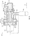
- FIG. 1 an inflation system 100.
- the inflation system 100 can be part of an emergency evacuation system such as a life raft, a float or an evacuation slide. All of these evacuation systems include an inflatable element that, in operation, is connected to an outlet 108 of the inflation system. When needed, which is more fully explained below, gas contained in the gas bottle 104 is provided through the outlet 108 to the inflatable element 201 causing inflation of the inflatable element.
- the gas bottle 104 is an example of pneumatic source.
- the inflatable element 201 can be a life raft, a float or an evacuation slide or any other inflatable device.
- the inflation system 100 includes a valve body 102.
- the valve body 102 includes an inlet 106 and the outlet 108.
- the gas bottle 104 is connected to the inlet 106 in a sealed manner to keep gas from escaping from the bottle as much as possible.
- a membrane 150 Located within the valve body 102 is a membrane 150.
- the membrane 150 prevents gas from the bottle 104 from reaching outlet 108.
- a solenoid valve 110 is connected to the valve body 102 and is used to cause certain other elements (e.g., knife edge piston 130) to puncture the member 150.
- the solenoid valve 110 causes the knife edge piston 130 to rupture the membrane 150 when the valve is activated. Rupturing the membrane 150 allows the gas in the gas bottle 104 to travel from the inlet 106 to the outlet 108 and inflate the connected inflatable element.
- the solenoid valve 110 is coupled to the valve body 102 and is a 2 position, 2 way normally closed in-line solenoid valve in one embodiment.
- the valve 110 includes an inlet 112 and an outlet 114. High pressure gas is drawn from the valve inlet 106 and is routed to the inlet 112 of solenoid valve. Upon electrical actuation, the solenoid valve 110 opens admitting high pressure gas into the valve body 102 and causing motion of the knife edge piston 130.
- the valve body 102 includes piston 130 disposed within it.
- the piston 130 includes a piston head 124 that is moveable retained in command cavity 120 of the valve body.
- the piston head can move in the direction A shown in FIG. 1 within the command cavity 120.
- a sealing element such as an o-ring 125 may surround the piston head 124 to seal gas from one side of the piston head 124 from traveling to the other side.
- the piston 130 also includes a knife end 131 that includes sharp edges 133 that can rupture membrane 150.
- the knife end 131 is contained and moves within the rupture cavity 135 of the valve body.
- the pressure of the gas in the rupture cavity 135 is as the pressure of the gas in the gas bottle 104. This pushes the piston head 124 to the left in FIG. 1A .
- the piston 130 may include another o-ring 142 to seal gas in the rupture cavity 135.
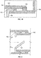
- the profile of the knife end 131 can be designed either to make full opening by dislodging the ruptured part of membrane 150 or to make an angular opening holding the partially ruptured part like a hinge assembly as shown FIG. 2 .
- the knife end 131 is integral with the piston 130.
- the piston includes piston head 124 and inner piston head 161. As described above, each head includes radial seals 125, 142 to hold the fluid pressure.
- inner piston head seal 142 experiences the fluid pressure within the main body and the piston head seal 125 experiences the fluid pressure in the command cavity 120.
- the leakage through the inner piston head seal 142 is vented out through vent port 128. This pressure force retains the piston 130 in the initial position withstanding the vibration and shock loads.
- leaked gas of the solenoid valve 110 is vented out through vent port 170.
- Springs 122 may also be provided in the command cavity and contacting the piston head 124 to provide for increased speed of rupturing action.
- the valve body 102 includes a removable disk retaining body 140.
- the disk retainer body 140 can be coupled to and removed from the rest of the valve body 102 (e.g., from main body portion 131) due to a threaded connection 156.
- the connection between the disk retaining body 140 and the valve body 102 is best shown in FIG. 1B which is a detail of region B in FIG. 1A .
- Threaded connection 156 allows the disk retaining body 140 to be removed after each bursting of the membrane 150 (or solenoid) firing and the remains of used disc can be removed by conventional machining. For the repeated use, new membrane shall be used and welded with retainer body.
- the membrane 150 blocks the path between the inlet 104 and the outlet 108.
- the membrane 150 may also be referred to as a rupture disk herein as it can be circular in one embodiment and is ruptured to allow for flow between the inlet 104 and the outlet 108. Edges of the rupture disk 150 are fusion welded to the retainer body 140 as shown by welds 154 in FIG. 1B .
- gas bottle is pressurized and the disc is designed to be flat withstanding the pressure in the forward acting direction.
- the amount of distance travelled by the piston 130 can be controlled by a stroke limit 162 between an edge of the piston head 130 and the valve body 102,
- the rupture disk 150 can include indentations 152.
- the indentations 152 may align with the knife end 131 to allow for easier rupturing.
- the disc 150 can be designed with a slight reverse buckling. This induces tensile stress in the disc 150 and final bursting or rupturing occurs under the punching action of the knife end 131. Rupturing action in the tensile loading condition burst the disc with full opening without fragmentation.
- strength is determined by the material used, thickness of material, manner in which disc is gripped or retained and the presence or absence of the initial surface imperfection and indentations 152 or scoring marks.
- the ruptured portion of the disk 150 is retained within retainer body by action the fluid pressure force. Since the flow outlet 108 is located 90 degrees away from the central flow path (arrow B), the dislodged disc part does not get into the valve outlet path. For the case of angular opening which does not require complete rupturing, the cutting profile of tool shall be designed accordingly.
- the solenoid 110 After the solenoid 110 is fired, it can be closed (e.g., reset) by disconnecting the electrical supply.
- Parameters of the rupturing action involves the type of disc 150 and its initial indentations 152, design of the knife edge profile of the knife end 130, the differential pressure force acting on the puncture tool and the speed with which the differential force builds up to for the movement and puncturing action.
- Other design parameters includes the solenoid valve port size, solenoid valve opening response time ,command cavity volume, spring force, oring sliding friction force, differential areas of the pistons and the travel distance of the puncher from the initial position. This component function as single action discharge valve with expendable rupture disc. The radial elastomer seals and the rupture disc need to be replaced after each firing.
- one or more embodiments disclosed herein will not allow for internal leaking from the gas bottle 104 to the outlet 108.
- the disc 150 can be replaced with new disc which can be fusion welded to the retainer 140. Except the rupture disc and two piston seals, all other parts are re-usable.
- the rupturing action be made smooth and uniform by the suitable designing of knife edge profile. If required, the profile can be designed to have an angular opening of the valve by rupturing the disc partially (e.g., FIG. 2 ). Since the rupturing action involves tensile loading of the rupture disc, the disc gets ruptured without fragmentation. In the rupturing with the full opening, the dislodged or ruptured piece part does not interfere with flow path. This design does not permit internal leakage and performs as zero leakage inflation valve. This design can be adapted to function at elevated operating temperature also.
Landscapes
- Engineering & Computer Science (AREA)
- General Engineering & Computer Science (AREA)
- Mechanical Engineering (AREA)
- Business, Economics & Management (AREA)
- Emergency Management (AREA)
- Aviation & Aerospace Engineering (AREA)
- Physics & Mathematics (AREA)
- General Physics & Mathematics (AREA)
- Automation & Control Theory (AREA)
- Safety Valves (AREA)
Abstract
Description
- This application claims priority to Indian Provisional Patent Application No.
201711018614 filed May 26, 2017 - The subject matter disclosed herein relates to inflation systems, and more particularly, to a system and a method for inflating an emergency evacuation device.
- Typically, inflatable evacuation devices such as floats, slides, and rafts are utilized to provide for aircraft occupant evacuations. Inflatable evacuation devices often utilize inflation systems to allow for the devices to be stored in a packed state and then rapidly inflated in emergency situations. Often, inflation systems utilized in inflatable evacuation devices can leak over time, causing pack growth and pack drop. Leakage from the inflation systems into the packed inflatable evacuation device requires the replacement of the inflatable evacuation devices.
- In more detail, pneumatic inflation system use high pressure stored gas, which needs to be discharged within specified time by the opening of a normally closed inflation valve. Typically, inflation valves are flow isolation valves actuated either by manual or electrical triggering. In operation, the inflation valve isolates the high pressure stored gas from the downstream inflatable pack. In the in-service conditions, the stored high pressure gas is effective up to the valve primary sealing, blocking the inlet - outlet flow path. The fluid leakage through this seal can be less than desirable. For instance, leaked gas flows down to the downstream inflatable if it is not vented leading to the aforementioned pack growth. Venting of this leaked gas to external ambient requires additional components which adds system complexity. Pack growth and drop both call for the replacement and maintenance of the inflatable pack assembly. This can lead to the inadvertent inflation and deployment in some instances.
- According to one embodiment, an inflation system that includes a gas source and a valve is disclosed. The valve includes a valve body, an inlet in the valve body in fluid communication with the gas and an outlet in the valve body, and a rupture disc in fluid communication with and between the inlet and the outlet that prevents fluid communication between the inlet and the outlet. The valve also includes a piston that is urged by a gas from the gas source to rupture the rupture disc to allow fluid communication between the gas source and the outlet.
- Also disclosed is a method to inflate an inflatable device. The method includes: providing a gas source in fluid communication with an inlet, preventing fluid communication between the inlet and an outlet via a rupture disc; urging a piston into the rupture disc via the pneumatic source; rupturing the rupture disc via the piston; and providing fluid communication between the pneumatic source and the inlet via the rupture disc.
- In one embodiment, an inflatable system that includes an inflatable device having a device inlet, and an inflation system is disclosed. The inflations system includes a gas source and a valve. The valve includes a valve body, an inlet in the valve body in fluid communication with the gas and an outlet in the valve body, and a rupture disc in fluid communication with and between the inlet and the outlet that prevents fluid communication between the inlet and the outlet. The valve also includes a piston that is urged by a gas from the gas source to rupture the rupture disc to allow fluid communication between the gas source and the outlet.
- A technical effect of the embodiments described above includes providing is a valve having zero internal leakage that can be used to in inflation systems.
- Other aspects, features, and techniques of the embodiments will become more apparent from the following description taken in conjunction with the drawings.
- The subject matter is particularly pointed out and distinctly claimed in the claims at the conclusion of the specification. The foregoing and other features, and advantages of the embodiments are apparent from the following detailed description taken in conjunction with the accompanying drawings in which like elements are numbered alike in the FIGURES:
-
FIG. 1A illustrates a partial cross-sectional view of one embodiment of an inflation system for use with an inflatable evacuation device; -
FIG. 1B is a detail view of the fusion weld and the threaded connection of the inflation system ofFIG. 1A ; and -
FIG. 2 is a pictorial view of the inflation system ofFIG. 1A shown in a ruptured state. - In the context of aircraft or other vehicle life rafts and floats, such emergency evacuation devices must last for a long time with minimum scheduled maintenance. As such, such systems need to include low or zero leakage inflation systems. Leakage is influenced by the sealing design type, sealing materials and the operating environments. The design parameters influencing the internal leakage need to be tightly controlled in the component processing to achieve valve assemblies meeting the required leak tightness. Disclosed herein is a valve having zero internal leakage features achieved by using fluid isolation rupture discs which can be retained by fusion welding them to an outer body (e.g., retainer body). To initiate the inflation, this disc is ruptured by a knife edge cutter tool (e.g., puncher) actuated by the electropneumatic action.
- Referring now to the drawings,
FIG. 1 aninflation system 100. Theinflation system 100 can be part of an emergency evacuation system such as a life raft, a float or an evacuation slide. All of these evacuation systems include an inflatable element that, in operation, is connected to anoutlet 108 of the inflation system. When needed, which is more fully explained below, gas contained in thegas bottle 104 is provided through theoutlet 108 to theinflatable element 201 causing inflation of the inflatable element. Thegas bottle 104 is an example of pneumatic source. Theinflatable element 201 can be a life raft, a float or an evacuation slide or any other inflatable device. - The
inflation system 100 includes avalve body 102. Thevalve body 102 includes aninlet 106 and theoutlet 108. Thegas bottle 104 is connected to theinlet 106 in a sealed manner to keep gas from escaping from the bottle as much as possible. - Located within the
valve body 102 is amembrane 150. Themembrane 150 prevents gas from thebottle 104 from reachingoutlet 108. Asolenoid valve 110 is connected to thevalve body 102 and is used to cause certain other elements (e.g., knife edge piston 130) to puncture themember 150. In general, thesolenoid valve 110 causes the knife edge piston 130 to rupture themembrane 150 when the valve is activated. Rupturing themembrane 150 allows the gas in thegas bottle 104 to travel from theinlet 106 to theoutlet 108 and inflate the connected inflatable element. - The
solenoid valve 110 is coupled to thevalve body 102 and is a 2 position, 2 way normally closed in-line solenoid valve in one embodiment. Thevalve 110 includes aninlet 112 and anoutlet 114. High pressure gas is drawn from thevalve inlet 106 and is routed to theinlet 112 of solenoid valve. Upon electrical actuation, thesolenoid valve 110 opens admitting high pressure gas into thevalve body 102 and causing motion of the knife edge piston 130. - In more detail, the
valve body 102 includes piston 130 disposed within it. The piston 130 includes apiston head 124 that is moveable retained incommand cavity 120 of the valve body. In one embodiment, the piston head can move in the direction A shown inFIG. 1 within thecommand cavity 120. A sealing element such as an o-ring 125 may surround thepiston head 124 to seal gas from one side of thepiston head 124 from traveling to the other side. - The piston 130 also includes a knife end 131 that includes
sharp edges 133 that can rupturemembrane 150. The knife end 131 is contained and moves within therupture cavity 135 of the valve body. - In normal operation, the pressure of the gas in the
rupture cavity 135 is as the pressure of the gas in thegas bottle 104. This pushes thepiston head 124 to the left inFIG. 1A . The piston 130 may include another o-ring 142 to seal gas in therupture cavity 135. - After the solenoid is activated, gas is provided through the solenoid outlet to the
command cavity 120 ofvalve body 102. The differential fluid pressure force moves the knife end 131 towards themembrane 150. The knife end 131 punctures the membrane and allows the gas to pass form theinlet 104 to theoutlet 108. - The profile of the knife end 131 can be designed either to make full opening by dislodging the ruptured part of
membrane 150 or to make an angular opening holding the partially ruptured part like a hinge assembly as shownFIG. 2 . - In one embodiment, the knife end 131 is integral with the piston 130. The piston includes
piston head 124 andinner piston head 161. As described above, each head includesradial seals piston head seal 142 experiences the fluid pressure within the main body and thepiston head seal 125 experiences the fluid pressure in thecommand cavity 120. The leakage through the innerpiston head seal 142 is vented out throughvent port 128. This pressure force retains the piston 130 in the initial position withstanding the vibration and shock loads. In the in-service condition, leaked gas of thesolenoid valve 110 is vented out throughvent port 170. -
Springs 122 may also be provided in the command cavity and contacting thepiston head 124 to provide for increased speed of rupturing action. - Opposite the solenoid, the
valve body 102 includes a removabledisk retaining body 140. Thedisk retainer body 140 can be coupled to and removed from the rest of the valve body 102 (e.g., from main body portion 131) due to a threadedconnection 156. The connection between thedisk retaining body 140 and thevalve body 102 is best shown inFIG. 1B which is a detail of region B inFIG. 1A . Threadedconnection 156 allows thedisk retaining body 140 to be removed after each bursting of the membrane 150 (or solenoid) firing and the remains of used disc can be removed by conventional machining. For the repeated use, new membrane shall be used and welded with retainer body. - The
membrane 150, as discussed above, blocks the path between theinlet 104 and theoutlet 108. Themembrane 150 may also be referred to as a rupture disk herein as it can be circular in one embodiment and is ruptured to allow for flow between theinlet 104 and theoutlet 108. Edges of therupture disk 150 are fusion welded to theretainer body 140 as shown bywelds 154 inFIG. 1B . In the final use, gas bottle is pressurized and the disc is designed to be flat withstanding the pressure in the forward acting direction. - The amount of distance travelled by the piston 130 can be controlled by a
stroke limit 162 between an edge of the piston head 130 and thevalve body 102, - With referent to
FIGs. 1A and1B , therupture disk 150 can includeindentations 152. Theindentations 152 may align with the knife end 131 to allow for easier rupturing. In some cases thedisc 150 can be designed with a slight reverse buckling. This induces tensile stress in thedisc 150 and final bursting or rupturing occurs under the punching action of the knife end 131. Rupturing action in the tensile loading condition burst the disc with full opening without fragmentation. For a givendisc 150 isolation sealing, strength is determined by the material used, thickness of material, manner in which disc is gripped or retained and the presence or absence of the initial surface imperfection andindentations 152 or scoring marks. - After firing of the solenoid 110 (e.g., the fully opened case), the ruptured portion of the
disk 150 is retained within retainer body by action the fluid pressure force. Since theflow outlet 108 is located 90 degrees away from the central flow path (arrow B), the dislodged disc part does not get into the valve outlet path. For the case of angular opening which does not require complete rupturing, the cutting profile of tool shall be designed accordingly. - After the
solenoid 110 is fired, it can be closed (e.g., reset) by disconnecting the electrical supply. - Parameters of the rupturing action involves the type of
disc 150 and itsinitial indentations 152, design of the knife edge profile of the knife end 130, the differential pressure force acting on the puncture tool and the speed with which the differential force builds up to for the movement and puncturing action. Other design parameters includes the solenoid valve port size, solenoid valve opening response time ,command cavity volume, spring force, oring sliding friction force, differential areas of the pistons and the travel distance of the puncher from the initial position. This component function as single action discharge valve with expendable rupture disc. The radial elastomer seals and the rupture disc need to be replaced after each firing. - Advantageously, one or more embodiments disclosed herein will not allow for internal leaking from the
gas bottle 104 to theoutlet 108. - After each disc rupturing, the
disc 150 can be replaced with new disc which can be fusion welded to theretainer 140. Except the rupture disc and two piston seals, all other parts are re-usable. The rupturing action be made smooth and uniform by the suitable designing of knife edge profile. If required, the profile can be designed to have an angular opening of the valve by rupturing the disc partially (e.g.,FIG. 2 ). Since the rupturing action involves tensile loading of the rupture disc, the disc gets ruptured without fragmentation. In the rupturing with the full opening, the dislodged or ruptured piece part does not interfere with flow path. This design does not permit internal leakage and performs as zero leakage inflation valve. This design can be adapted to function at elevated operating temperature also. - The terminology used herein is for the purpose of describing particular embodiments only and is not intended to be limiting of the embodiments. While the description of the present embodiments has been presented for purposes of illustration and description, it is not intended to be exhaustive or limited to the embodiments in the form disclosed. Many modifications, variations, alterations, substitutions or equivalent arrangement not hereto described will be apparent to those of ordinary skill in the art without departing from the scope of the embodiments. Additionally, while various embodiments have been described, it is to be understood that aspects may include only some of the described embodiments. Accordingly, the embodiments are not to be seen as limited by the foregoing description, but are only limited by the scope of the appended claims.
Claims (15)
- An inflation system (100), comprising:a gas source (104);a valve including:a valve body (102);an inlet (106) in the valve body in fluid communication with the gas source;an outlet (108) in the valve body;a rupture disc (150) in fluid communication with and between the inlet and the outlet, wherein the rupture disc prevents fluid communication between the inlet and the outlet; anda piston (130), wherein the piston is urged by a gas from the gas source to rupture the rupture disc to allow fluid communication between the gas source and the outlet.
- The inflation system of claim 1, wherein the valve body (102) includes a body portion and a disc retaining body connected to the body portion, the inlet being formed in the body portion and the outlet being formed in the disk retaining body.
- The inflation system of claim 2, wherein the rupture disc (150) is fusion welded to the disc retaining body.
- The inflation system of claim 3, wherein the disc retaining body includes a threaded connection.
- The inflation system of any preceding claim, wherein the rupture disc (150) includes an indentation.
- The inflation system of any preceding claim, further comprising a solenoid valve (110) to selectively allow flow between the gas source and the rupture disk.
- The inflation system of claim 6, wherein the solenoid valve (110) selectively allows flow into a command cavity defined by the rupture member.
- The inflation system of any preceding claim, wherein the piston (130) includes a knife edge.
- The inflation system of any preceding claim, wherein the gas source (104) is a gas bottle.
- A method to inflate an inflatable device, the method comprising:providing a gas source in fluid communication with an inlet;preventing fluid communication between the inlet and an outlet via a rupture disc;urging a piston into the rupture disc via the gas source;rupturing the rupture disc via the piston; andproviding fluid communication between the gas source and the outlet via the rupture disc.
- The method of claim 10, wherein the rupture disc is disposed in a disc retaining body.
- The method of claim 11, further comprising fusion welding the rupture disc to the disc retaining body.
- The method of any of claims 10-12, wherein the disc retaining body includes a threaded connection and the rupture disc includes an indentation.
- The method of any of claims 10-13, further comprising selectively allowing flow between the pneumatic source and the rupture member via a solenoid valve.
- The method of claim 14, further comprising selectively allowing flow into a command cavity defined by the rupture member via the solenoid valve.
Applications Claiming Priority (1)
| Application Number | Priority Date | Filing Date | Title |
|---|---|---|---|
| IN201711018614 | 2017-05-26 |
Publications (2)
| Publication Number | Publication Date |
|---|---|
| EP3406948A1 true EP3406948A1 (en) | 2018-11-28 |
| EP3406948B1 EP3406948B1 (en) | 2020-11-25 |
Family
ID=62386083
Family Applications (1)
| Application Number | Title | Priority Date | Filing Date |
|---|---|---|---|
| EP18174244.6A Not-in-force EP3406948B1 (en) | 2017-05-26 | 2018-05-25 | Pneumatic inflation system |
Country Status (2)
| Country | Link |
|---|---|
| US (1) | US10481620B2 (en) |
| EP (1) | EP3406948B1 (en) |
Families Citing this family (13)
| Publication number | Priority date | Publication date | Assignee | Title |
|---|---|---|---|---|
| US10946971B2 (en) * | 2018-08-17 | 2021-03-16 | Goodrich Corporation | Inflation control system |
| US11119516B2 (en) | 2019-12-11 | 2021-09-14 | Goodrich Coproration | Solenoid-operated pressure-regulator modules for inflation systems and methods thereof |
| US11169552B2 (en) | 2019-12-13 | 2021-11-09 | Goodrich Corporation | Solenoid initiator with a manual override for inflation system |
| CN111959716B (en) * | 2020-08-14 | 2021-07-30 | 湖南大平安安全科技有限公司 | Inflatable rescue equipment |
| US20220196181A1 (en) * | 2020-12-23 | 2022-06-23 | Goodrich Corporation | Inflatable systems with electro-pneumatic valve modules |
| WO2023119209A1 (en) | 2021-12-23 | 2023-06-29 | Astrix Astronautics Limited | Inflatable structures of or for spacecraft |
| US12092233B2 (en) * | 2022-04-29 | 2024-09-17 | Goodrich Corporation | Electrically operated pressure regulator with rupture disc isolation valve for inflation system |
| US11802629B1 (en) * | 2022-05-18 | 2023-10-31 | Goodrich Corporation | Solenoid actuated pressure regulator for inflation system |
| US11859770B1 (en) | 2022-06-14 | 2024-01-02 | Goodrich Corporation | Compressed gas cylinder actuation device |
| EP4293273B1 (en) * | 2022-06-14 | 2026-02-25 | Goodrich Corporation | Compressed gas cylinder actuation device |
| US12203600B2 (en) | 2022-07-22 | 2025-01-21 | Goodrich Corporation | Magneto strictive actuated pressure regulator module for inflation system |
| EP4310384B1 (en) * | 2022-07-22 | 2025-12-03 | Goodrich Corporation | Magneto strictive actuated pressure regulator module for inflation system |
| CN116085509A (en) * | 2023-01-19 | 2023-05-09 | 哲弗智能系统(上海)有限公司 | Divide accuse valve and fire extinguishing systems |
Citations (3)
| Publication number | Priority date | Publication date | Assignee | Title |
|---|---|---|---|---|
| US6089403A (en) * | 1997-11-25 | 2000-07-18 | Mackal; Glenn H. | Inflation system with pneumatic assist |
| US20050098209A1 (en) * | 2003-09-08 | 2005-05-12 | Mackal Glenn H. | Inflation valve with pneumatic assist |
| US20050103379A1 (en) * | 2002-04-19 | 2005-05-19 | Goran Sundholm | Valve element |
Family Cites Families (11)
| Publication number | Priority date | Publication date | Assignee | Title |
|---|---|---|---|---|
| USRE30552E (en) * | 1979-06-25 | 1981-03-24 | Tom Mcguane Industries, Inc. | Fuel vapor vent valve |
| US4476937A (en) | 1982-10-08 | 1984-10-16 | The United States Of America As Represented By The Secretary Of The Army | Rapid acting two stage pyrotechnic valve for fixed fire extinguishers |
| US4500014A (en) * | 1982-12-14 | 1985-02-19 | Halkey-Roberts Corp. | Multiple firing inflator |
| US4669626A (en) * | 1983-09-20 | 1987-06-02 | Continental Disc Corporation | Rupture disc with selectively positioned initial buckling |
| US4959034A (en) * | 1988-10-25 | 1990-09-25 | Wass Lloyd G | Puncture disc inflation valve with improved cutting bayonet |
| US5860443A (en) | 1997-02-28 | 1999-01-19 | Breed Automotive Technology, Inc. | Rapid release mechanism with damping control |
| US6260570B1 (en) | 1997-06-16 | 2001-07-17 | Lloyd G. Wass | Puncture disc raft inflation valve having a one-piece valve body |
| US7878215B2 (en) | 2008-11-21 | 2011-02-01 | Fike Corporation | Impulse actuated valve |
| WO2014018332A1 (en) | 2012-07-23 | 2014-01-30 | Carleton Technologies, Inc. | Inflator assembly adapted for manual or automatic inflation |
| US9649520B2 (en) | 2014-07-11 | 2017-05-16 | Kidde Technologies, Inc. | Burst disc puncture pressure-imbalance actuator for a fire extinguisher |
| US10011332B2 (en) * | 2015-03-17 | 2018-07-03 | Bogdan Michalski | Modular electronic activation system |
-
2017
- 2017-09-20 US US15/709,715 patent/US10481620B2/en active Active
-
2018
- 2018-05-25 EP EP18174244.6A patent/EP3406948B1/en not_active Not-in-force
Patent Citations (3)
| Publication number | Priority date | Publication date | Assignee | Title |
|---|---|---|---|---|
| US6089403A (en) * | 1997-11-25 | 2000-07-18 | Mackal; Glenn H. | Inflation system with pneumatic assist |
| US20050103379A1 (en) * | 2002-04-19 | 2005-05-19 | Goran Sundholm | Valve element |
| US20050098209A1 (en) * | 2003-09-08 | 2005-05-12 | Mackal Glenn H. | Inflation valve with pneumatic assist |
Also Published As
| Publication number | Publication date |
|---|---|
| EP3406948B1 (en) | 2020-11-25 |
| US20180341279A1 (en) | 2018-11-29 |
| US10481620B2 (en) | 2019-11-19 |
Similar Documents
| Publication | Publication Date | Title |
|---|---|---|
| EP3406948B1 (en) | Pneumatic inflation system | |
| EP3569921B1 (en) | Poppet type pneumatic valve for inflation system | |
| US11598445B2 (en) | Inflation valve assembly | |
| US3645286A (en) | Safety valve for liquid pressure cylinders | |
| EP3060832B1 (en) | Systems and methods for cascading burst discs | |
| EP3360773B1 (en) | Solenoid valve for inflation system | |
| EP3360772B1 (en) | Solenoid valve for inflation system | |
| CN107024323B (en) | Leak inspection device and leak inspection method | |
| EP3473903B1 (en) | Electro-pneumatic valve assembly | |
| EP2636932A1 (en) | Pinch valve having integrated pressure chamber | |
| US20100163763A1 (en) | Pilot operated vacuum packable inflation system | |
| EP3550144B1 (en) | Reduced pressurization shift within diaphragm pump cavity | |
| EP1942295B1 (en) | Floating lifter pressure relief valve | |
| US10261526B2 (en) | Pressure reducing valve | |
| EP4202286A1 (en) | A release valve | |
| CN212338309U (en) | A normally open safety valve with a bursting disc | |
| EP4293273B1 (en) | Compressed gas cylinder actuation device | |
| US11859770B1 (en) | Compressed gas cylinder actuation device | |
| US4476937A (en) | Rapid acting two stage pyrotechnic valve for fixed fire extinguishers | |
| US20200056708A1 (en) | Trigger mechanism for a valve assembly | |
| MX2022000239A (en) | PRESSURE REGULATION SYSTEM FOR A BEVERAGE CONTAINER AND A BEVERAGE CONTAINER PROVIDED THERETO. | |
| CA3170489A1 (en) | Pneumatic release system | |
| GB2291172A (en) | Gas release valve | |
| RU25500U1 (en) | FILLING A LIQUEFIED GAS | |
| HK1204037A1 (en) | Pneumatic gate valve with integrated pressurized gas reservoir |
Legal Events
| Date | Code | Title | Description |
|---|---|---|---|
| PUAI | Public reference made under article 153(3) epc to a published international application that has entered the european phase |
Free format text: ORIGINAL CODE: 0009012 |
|
| STAA | Information on the status of an ep patent application or granted ep patent |
Free format text: STATUS: THE APPLICATION HAS BEEN PUBLISHED |
|
| AK | Designated contracting states |
Kind code of ref document: A1 Designated state(s): AL AT BE BG CH CY CZ DE DK EE ES FI FR GB GR HR HU IE IS IT LI LT LU LV MC MK MT NL NO PL PT RO RS SE SI SK SM TR |
|
| AX | Request for extension of the european patent |
Extension state: BA ME |
|
| STAA | Information on the status of an ep patent application or granted ep patent |
Free format text: STATUS: REQUEST FOR EXAMINATION WAS MADE |
|
| 17P | Request for examination filed |
Effective date: 20190528 |
|
| RBV | Designated contracting states (corrected) |
Designated state(s): AL AT BE BG CH CY CZ DE DK EE ES FI FR GB GR HR HU IE IS IT LI LT LU LV MC MK MT NL NO PL PT RO RS SE SI SK SM TR |
|
| STAA | Information on the status of an ep patent application or granted ep patent |
Free format text: STATUS: EXAMINATION IS IN PROGRESS |
|
| 17Q | First examination report despatched |
Effective date: 20191017 |
|
| GRAP | Despatch of communication of intention to grant a patent |
Free format text: ORIGINAL CODE: EPIDOSNIGR1 |
|
| STAA | Information on the status of an ep patent application or granted ep patent |
Free format text: STATUS: GRANT OF PATENT IS INTENDED |
|
| INTG | Intention to grant announced |
Effective date: 20200609 |
|
| GRAS | Grant fee paid |
Free format text: ORIGINAL CODE: EPIDOSNIGR3 |
|
| GRAA | (expected) grant |
Free format text: ORIGINAL CODE: 0009210 |
|
| STAA | Information on the status of an ep patent application or granted ep patent |
Free format text: STATUS: THE PATENT HAS BEEN GRANTED |
|
| AK | Designated contracting states |
Kind code of ref document: B1 Designated state(s): AL AT BE BG CH CY CZ DE DK EE ES FI FR GB GR HR HU IE IS IT LI LT LU LV MC MK MT NL NO PL PT RO RS SE SI SK SM TR |
|
| REG | Reference to a national code |
Ref country code: GB Ref legal event code: FG4D |
|
| REG | Reference to a national code |
Ref country code: CH Ref legal event code: EP |
|
| REG | Reference to a national code |
Ref country code: AT Ref legal event code: REF Ref document number: 1338729 Country of ref document: AT Kind code of ref document: T Effective date: 20201215 |
|
| REG | Reference to a national code |
Ref country code: DE Ref legal event code: R096 Ref document number: 602018010019 Country of ref document: DE |
|
| REG | Reference to a national code |
Ref country code: IE Ref legal event code: FG4D |
|
| REG | Reference to a national code |
Ref country code: AT Ref legal event code: MK05 Ref document number: 1338729 Country of ref document: AT Kind code of ref document: T Effective date: 20201125 |
|
| REG | Reference to a national code |
Ref country code: NL Ref legal event code: MP Effective date: 20201125 |
|
| PG25 | Lapsed in a contracting state [announced via postgrant information from national office to epo] |
Ref country code: NO Free format text: LAPSE BECAUSE OF FAILURE TO SUBMIT A TRANSLATION OF THE DESCRIPTION OR TO PAY THE FEE WITHIN THE PRESCRIBED TIME-LIMIT Effective date: 20210225 Ref country code: GR Free format text: LAPSE BECAUSE OF FAILURE TO SUBMIT A TRANSLATION OF THE DESCRIPTION OR TO PAY THE FEE WITHIN THE PRESCRIBED TIME-LIMIT Effective date: 20210226 Ref country code: FI Free format text: LAPSE BECAUSE OF FAILURE TO SUBMIT A TRANSLATION OF THE DESCRIPTION OR TO PAY THE FEE WITHIN THE PRESCRIBED TIME-LIMIT Effective date: 20201125 Ref country code: PT Free format text: LAPSE BECAUSE OF FAILURE TO SUBMIT A TRANSLATION OF THE DESCRIPTION OR TO PAY THE FEE WITHIN THE PRESCRIBED TIME-LIMIT Effective date: 20210325 Ref country code: RS Free format text: LAPSE BECAUSE OF FAILURE TO SUBMIT A TRANSLATION OF THE DESCRIPTION OR TO PAY THE FEE WITHIN THE PRESCRIBED TIME-LIMIT Effective date: 20201125 |
|
| PG25 | Lapsed in a contracting state [announced via postgrant information from national office to epo] |
Ref country code: AT Free format text: LAPSE BECAUSE OF FAILURE TO SUBMIT A TRANSLATION OF THE DESCRIPTION OR TO PAY THE FEE WITHIN THE PRESCRIBED TIME-LIMIT Effective date: 20201125 Ref country code: LV Free format text: LAPSE BECAUSE OF FAILURE TO SUBMIT A TRANSLATION OF THE DESCRIPTION OR TO PAY THE FEE WITHIN THE PRESCRIBED TIME-LIMIT Effective date: 20201125 Ref country code: PL Free format text: LAPSE BECAUSE OF FAILURE TO SUBMIT A TRANSLATION OF THE DESCRIPTION OR TO PAY THE FEE WITHIN THE PRESCRIBED TIME-LIMIT Effective date: 20201125 Ref country code: IS Free format text: LAPSE BECAUSE OF FAILURE TO SUBMIT A TRANSLATION OF THE DESCRIPTION OR TO PAY THE FEE WITHIN THE PRESCRIBED TIME-LIMIT Effective date: 20210325 Ref country code: SE Free format text: LAPSE BECAUSE OF FAILURE TO SUBMIT A TRANSLATION OF THE DESCRIPTION OR TO PAY THE FEE WITHIN THE PRESCRIBED TIME-LIMIT Effective date: 20201125 Ref country code: BG Free format text: LAPSE BECAUSE OF FAILURE TO SUBMIT A TRANSLATION OF THE DESCRIPTION OR TO PAY THE FEE WITHIN THE PRESCRIBED TIME-LIMIT Effective date: 20210225 |
|
| REG | Reference to a national code |
Ref country code: LT Ref legal event code: MG9D |
|
| PG25 | Lapsed in a contracting state [announced via postgrant information from national office to epo] |
Ref country code: HR Free format text: LAPSE BECAUSE OF FAILURE TO SUBMIT A TRANSLATION OF THE DESCRIPTION OR TO PAY THE FEE WITHIN THE PRESCRIBED TIME-LIMIT Effective date: 20201125 |
|
| PG25 | Lapsed in a contracting state [announced via postgrant information from national office to epo] |
Ref country code: SK Free format text: LAPSE BECAUSE OF FAILURE TO SUBMIT A TRANSLATION OF THE DESCRIPTION OR TO PAY THE FEE WITHIN THE PRESCRIBED TIME-LIMIT Effective date: 20201125 Ref country code: RO Free format text: LAPSE BECAUSE OF FAILURE TO SUBMIT A TRANSLATION OF THE DESCRIPTION OR TO PAY THE FEE WITHIN THE PRESCRIBED TIME-LIMIT Effective date: 20201125 Ref country code: LT Free format text: LAPSE BECAUSE OF FAILURE TO SUBMIT A TRANSLATION OF THE DESCRIPTION OR TO PAY THE FEE WITHIN THE PRESCRIBED TIME-LIMIT Effective date: 20201125 Ref country code: EE Free format text: LAPSE BECAUSE OF FAILURE TO SUBMIT A TRANSLATION OF THE DESCRIPTION OR TO PAY THE FEE WITHIN THE PRESCRIBED TIME-LIMIT Effective date: 20201125 Ref country code: CZ Free format text: LAPSE BECAUSE OF FAILURE TO SUBMIT A TRANSLATION OF THE DESCRIPTION OR TO PAY THE FEE WITHIN THE PRESCRIBED TIME-LIMIT Effective date: 20201125 Ref country code: SM Free format text: LAPSE BECAUSE OF FAILURE TO SUBMIT A TRANSLATION OF THE DESCRIPTION OR TO PAY THE FEE WITHIN THE PRESCRIBED TIME-LIMIT Effective date: 20201125 |
|
| REG | Reference to a national code |
Ref country code: DE Ref legal event code: R097 Ref document number: 602018010019 Country of ref document: DE |
|
| PG25 | Lapsed in a contracting state [announced via postgrant information from national office to epo] |
Ref country code: DK Free format text: LAPSE BECAUSE OF FAILURE TO SUBMIT A TRANSLATION OF THE DESCRIPTION OR TO PAY THE FEE WITHIN THE PRESCRIBED TIME-LIMIT Effective date: 20201125 |
|
| PLBE | No opposition filed within time limit |
Free format text: ORIGINAL CODE: 0009261 |
|
| STAA | Information on the status of an ep patent application or granted ep patent |
Free format text: STATUS: NO OPPOSITION FILED WITHIN TIME LIMIT |
|
| PG25 | Lapsed in a contracting state [announced via postgrant information from national office to epo] |
Ref country code: IT Free format text: LAPSE BECAUSE OF FAILURE TO SUBMIT A TRANSLATION OF THE DESCRIPTION OR TO PAY THE FEE WITHIN THE PRESCRIBED TIME-LIMIT Effective date: 20201125 Ref country code: AL Free format text: LAPSE BECAUSE OF FAILURE TO SUBMIT A TRANSLATION OF THE DESCRIPTION OR TO PAY THE FEE WITHIN THE PRESCRIBED TIME-LIMIT Effective date: 20201125 Ref country code: NL Free format text: LAPSE BECAUSE OF FAILURE TO SUBMIT A TRANSLATION OF THE DESCRIPTION OR TO PAY THE FEE WITHIN THE PRESCRIBED TIME-LIMIT Effective date: 20201125 |
|
| 26N | No opposition filed |
Effective date: 20210826 |
|
| PG25 | Lapsed in a contracting state [announced via postgrant information from national office to epo] |
Ref country code: SI Free format text: LAPSE BECAUSE OF FAILURE TO SUBMIT A TRANSLATION OF THE DESCRIPTION OR TO PAY THE FEE WITHIN THE PRESCRIBED TIME-LIMIT Effective date: 20201125 |
|
| REG | Reference to a national code |
Ref country code: CH Ref legal event code: PL |
|
| PG25 | Lapsed in a contracting state [announced via postgrant information from national office to epo] |
Ref country code: MC Free format text: LAPSE BECAUSE OF FAILURE TO SUBMIT A TRANSLATION OF THE DESCRIPTION OR TO PAY THE FEE WITHIN THE PRESCRIBED TIME-LIMIT Effective date: 20201125 Ref country code: LI Free format text: LAPSE BECAUSE OF NON-PAYMENT OF DUE FEES Effective date: 20210531 Ref country code: LU Free format text: LAPSE BECAUSE OF NON-PAYMENT OF DUE FEES Effective date: 20210525 Ref country code: CH Free format text: LAPSE BECAUSE OF NON-PAYMENT OF DUE FEES Effective date: 20210531 Ref country code: ES Free format text: LAPSE BECAUSE OF FAILURE TO SUBMIT A TRANSLATION OF THE DESCRIPTION OR TO PAY THE FEE WITHIN THE PRESCRIBED TIME-LIMIT Effective date: 20201125 |
|
| REG | Reference to a national code |
Ref country code: BE Ref legal event code: MM Effective date: 20210531 |
|
| PG25 | Lapsed in a contracting state [announced via postgrant information from national office to epo] |
Ref country code: IE Free format text: LAPSE BECAUSE OF NON-PAYMENT OF DUE FEES Effective date: 20210525 |
|
| PG25 | Lapsed in a contracting state [announced via postgrant information from national office to epo] |
Ref country code: IS Free format text: LAPSE BECAUSE OF FAILURE TO SUBMIT A TRANSLATION OF THE DESCRIPTION OR TO PAY THE FEE WITHIN THE PRESCRIBED TIME-LIMIT Effective date: 20210325 |
|
| PG25 | Lapsed in a contracting state [announced via postgrant information from national office to epo] |
Ref country code: BE Free format text: LAPSE BECAUSE OF NON-PAYMENT OF DUE FEES Effective date: 20210531 |
|
| GBPC | Gb: european patent ceased through non-payment of renewal fee |
Effective date: 20220525 |
|
| PG25 | Lapsed in a contracting state [announced via postgrant information from national office to epo] |
Ref country code: GB Free format text: LAPSE BECAUSE OF NON-PAYMENT OF DUE FEES Effective date: 20220525 |
|
| P01 | Opt-out of the competence of the unified patent court (upc) registered |
Effective date: 20230521 |
|
| PG25 | Lapsed in a contracting state [announced via postgrant information from national office to epo] |
Ref country code: CY Free format text: LAPSE BECAUSE OF FAILURE TO SUBMIT A TRANSLATION OF THE DESCRIPTION OR TO PAY THE FEE WITHIN THE PRESCRIBED TIME-LIMIT Effective date: 20201125 |
|
| PG25 | Lapsed in a contracting state [announced via postgrant information from national office to epo] |
Ref country code: HU Free format text: LAPSE BECAUSE OF FAILURE TO SUBMIT A TRANSLATION OF THE DESCRIPTION OR TO PAY THE FEE WITHIN THE PRESCRIBED TIME-LIMIT; INVALID AB INITIO Effective date: 20180525 |
|
| PG25 | Lapsed in a contracting state [announced via postgrant information from national office to epo] |
Ref country code: MK Free format text: LAPSE BECAUSE OF FAILURE TO SUBMIT A TRANSLATION OF THE DESCRIPTION OR TO PAY THE FEE WITHIN THE PRESCRIBED TIME-LIMIT Effective date: 20201125 |
|
| PGFP | Annual fee paid to national office [announced via postgrant information from national office to epo] |
Ref country code: DE Payment date: 20240418 Year of fee payment: 7 |
|
| PGFP | Annual fee paid to national office [announced via postgrant information from national office to epo] |
Ref country code: FR Payment date: 20240418 Year of fee payment: 7 |
|
| PG25 | Lapsed in a contracting state [announced via postgrant information from national office to epo] |
Ref country code: MT Free format text: LAPSE BECAUSE OF FAILURE TO SUBMIT A TRANSLATION OF THE DESCRIPTION OR TO PAY THE FEE WITHIN THE PRESCRIBED TIME-LIMIT Effective date: 20201125 |
|
| REG | Reference to a national code |
Ref country code: DE Ref legal event code: R119 Ref document number: 602018010019 Country of ref document: DE |
|
| PG25 | Lapsed in a contracting state [announced via postgrant information from national office to epo] |
Ref country code: TR Free format text: LAPSE BECAUSE OF FAILURE TO SUBMIT A TRANSLATION OF THE DESCRIPTION OR TO PAY THE FEE WITHIN THE PRESCRIBED TIME-LIMIT Effective date: 20201125 |
|
| PG25 | Lapsed in a contracting state [announced via postgrant information from national office to epo] |
Ref country code: DE Free format text: LAPSE BECAUSE OF NON-PAYMENT OF DUE FEES Effective date: 20251202 |
|
| PG25 | Lapsed in a contracting state [announced via postgrant information from national office to epo] |
Ref country code: FR Free format text: LAPSE BECAUSE OF NON-PAYMENT OF DUE FEES Effective date: 20250531 |