EP3406893A1 - System and method for estimating consumed battery life of a pitch system of a wind turbine - Google Patents
System and method for estimating consumed battery life of a pitch system of a wind turbine Download PDFInfo
- Publication number
- EP3406893A1 EP3406893A1 EP17382298.2A EP17382298A EP3406893A1 EP 3406893 A1 EP3406893 A1 EP 3406893A1 EP 17382298 A EP17382298 A EP 17382298A EP 3406893 A1 EP3406893 A1 EP 3406893A1
- Authority
- EP
- European Patent Office
- Prior art keywords
- battery
- battery life
- consumed
- predetermined threshold
- cabinet
- Prior art date
- Legal status (The legal status is an assumption and is not a legal conclusion. Google has not performed a legal analysis and makes no representation as to the accuracy of the status listed.)
- Granted
Links
Images



Classifications
-
- F—MECHANICAL ENGINEERING; LIGHTING; HEATING; WEAPONS; BLASTING
- F03—MACHINES OR ENGINES FOR LIQUIDS; WIND, SPRING, OR WEIGHT MOTORS; PRODUCING MECHANICAL POWER OR A REACTIVE PROPULSIVE THRUST, NOT OTHERWISE PROVIDED FOR
- F03D—WIND MOTORS
- F03D17/00—Monitoring or testing of wind motors, e.g. diagnostics
-
- F—MECHANICAL ENGINEERING; LIGHTING; HEATING; WEAPONS; BLASTING
- F03—MACHINES OR ENGINES FOR LIQUIDS; WIND, SPRING, OR WEIGHT MOTORS; PRODUCING MECHANICAL POWER OR A REACTIVE PROPULSIVE THRUST, NOT OTHERWISE PROVIDED FOR
- F03D—WIND MOTORS
- F03D7/00—Controlling wind motors
- F03D7/02—Controlling wind motors the wind motors having rotation axis substantially parallel to the air flow entering the rotor
- F03D7/022—Adjusting aerodynamic properties of the blades
- F03D7/0224—Adjusting blade pitch
-
- F—MECHANICAL ENGINEERING; LIGHTING; HEATING; WEAPONS; BLASTING
- F03—MACHINES OR ENGINES FOR LIQUIDS; WIND, SPRING, OR WEIGHT MOTORS; PRODUCING MECHANICAL POWER OR A REACTIVE PROPULSIVE THRUST, NOT OTHERWISE PROVIDED FOR
- F03D—WIND MOTORS
- F03D7/00—Controlling wind motors
- F03D7/02—Controlling wind motors the wind motors having rotation axis substantially parallel to the air flow entering the rotor
- F03D7/0264—Controlling wind motors the wind motors having rotation axis substantially parallel to the air flow entering the rotor for stopping; controlling in emergency situations
-
- G—PHYSICS
- G01—MEASURING; TESTING
- G01N—INVESTIGATING OR ANALYSING MATERIALS BY DETERMINING THEIR CHEMICAL OR PHYSICAL PROPERTIES
- G01N25/00—Investigating or analyzing materials by the use of thermal means
-
- F—MECHANICAL ENGINEERING; LIGHTING; HEATING; WEAPONS; BLASTING
- F05—INDEXING SCHEMES RELATING TO ENGINES OR PUMPS IN VARIOUS SUBCLASSES OF CLASSES F01-F04
- F05B—INDEXING SCHEME RELATING TO WIND, SPRING, WEIGHT, INERTIA OR LIKE MOTORS, TO MACHINES OR ENGINES FOR LIQUIDS COVERED BY SUBCLASSES F03B, F03D AND F03G
- F05B2260/00—Function
- F05B2260/70—Adjusting of angle of incidence or attack of rotating blades
- F05B2260/74—Adjusting of angle of incidence or attack of rotating blades by turning around an axis perpendicular the rotor centre line
-
- F—MECHANICAL ENGINEERING; LIGHTING; HEATING; WEAPONS; BLASTING
- F05—INDEXING SCHEMES RELATING TO ENGINES OR PUMPS IN VARIOUS SUBCLASSES OF CLASSES F01-F04
- F05B—INDEXING SCHEME RELATING TO WIND, SPRING, WEIGHT, INERTIA OR LIKE MOTORS, TO MACHINES OR ENGINES FOR LIQUIDS COVERED BY SUBCLASSES F03B, F03D AND F03G
- F05B2260/00—Function
- F05B2260/80—Diagnostics
-
- F—MECHANICAL ENGINEERING; LIGHTING; HEATING; WEAPONS; BLASTING
- F05—INDEXING SCHEMES RELATING TO ENGINES OR PUMPS IN VARIOUS SUBCLASSES OF CLASSES F01-F04
- F05B—INDEXING SCHEME RELATING TO WIND, SPRING, WEIGHT, INERTIA OR LIKE MOTORS, TO MACHINES OR ENGINES FOR LIQUIDS COVERED BY SUBCLASSES F03B, F03D AND F03G
- F05B2260/00—Function
- F05B2260/82—Forecasts
- F05B2260/821—Parameter estimation or prediction
-
- F—MECHANICAL ENGINEERING; LIGHTING; HEATING; WEAPONS; BLASTING
- F05—INDEXING SCHEMES RELATING TO ENGINES OR PUMPS IN VARIOUS SUBCLASSES OF CLASSES F01-F04
- F05B—INDEXING SCHEME RELATING TO WIND, SPRING, WEIGHT, INERTIA OR LIKE MOTORS, TO MACHINES OR ENGINES FOR LIQUIDS COVERED BY SUBCLASSES F03B, F03D AND F03G
- F05B2260/00—Function
- F05B2260/84—Modelling or simulation
-
- F—MECHANICAL ENGINEERING; LIGHTING; HEATING; WEAPONS; BLASTING
- F05—INDEXING SCHEMES RELATING TO ENGINES OR PUMPS IN VARIOUS SUBCLASSES OF CLASSES F01-F04
- F05B—INDEXING SCHEME RELATING TO WIND, SPRING, WEIGHT, INERTIA OR LIKE MOTORS, TO MACHINES OR ENGINES FOR LIQUIDS COVERED BY SUBCLASSES F03B, F03D AND F03G
- F05B2270/00—Control
- F05B2270/10—Purpose of the control system
- F05B2270/107—Purpose of the control system to cope with emergencies
- F05B2270/1074—Purpose of the control system to cope with emergencies by using back-up controls
-
- F—MECHANICAL ENGINEERING; LIGHTING; HEATING; WEAPONS; BLASTING
- F05—INDEXING SCHEMES RELATING TO ENGINES OR PUMPS IN VARIOUS SUBCLASSES OF CLASSES F01-F04
- F05B—INDEXING SCHEME RELATING TO WIND, SPRING, WEIGHT, INERTIA OR LIKE MOTORS, TO MACHINES OR ENGINES FOR LIQUIDS COVERED BY SUBCLASSES F03B, F03D AND F03G
- F05B2270/00—Control
- F05B2270/30—Control parameters, e.g. input parameters
- F05B2270/303—Temperature
-
- F—MECHANICAL ENGINEERING; LIGHTING; HEATING; WEAPONS; BLASTING
- F05—INDEXING SCHEMES RELATING TO ENGINES OR PUMPS IN VARIOUS SUBCLASSES OF CLASSES F01-F04
- F05B—INDEXING SCHEME RELATING TO WIND, SPRING, WEIGHT, INERTIA OR LIKE MOTORS, TO MACHINES OR ENGINES FOR LIQUIDS COVERED BY SUBCLASSES F03B, F03D AND F03G
- F05B2270/00—Control
- F05B2270/40—Type of control system
- F05B2270/404—Type of control system active, predictive, or anticipative
-
- Y—GENERAL TAGGING OF NEW TECHNOLOGICAL DEVELOPMENTS; GENERAL TAGGING OF CROSS-SECTIONAL TECHNOLOGIES SPANNING OVER SEVERAL SECTIONS OF THE IPC; TECHNICAL SUBJECTS COVERED BY FORMER USPC CROSS-REFERENCE ART COLLECTIONS [XRACs] AND DIGESTS
- Y02—TECHNOLOGIES OR APPLICATIONS FOR MITIGATION OR ADAPTATION AGAINST CLIMATE CHANGE
- Y02E—REDUCTION OF GREENHOUSE GAS [GHG] EMISSIONS, RELATED TO ENERGY GENERATION, TRANSMISSION OR DISTRIBUTION
- Y02E10/00—Energy generation through renewable energy sources
- Y02E10/70—Wind energy
- Y02E10/72—Wind turbines with rotation axis in wind direction
Definitions
- the present disclosure relates generally to wind turbines, and more particularly to systems and methods for estimating the consumed battery life of a pitch system of a wind turbine based on temperature.
- a modem wind turbine typically includes a tower, a generator, a gearbox, a nacelle, and a rotor including one or more rotor blades.
- the rotor blades capture kinetic energy from wind using known foil principles and transmit the kinetic energy through rotational energy to turn a shaft coupling the rotor blades to a gearbox, or if a gearbox is not used, directly to the generator.
- the generator then converts the mechanical energy to electrical energy that may be deployed to a utility grid.
- the direction of the wind which powers the wind turbine may change.
- the wind turbine may thus adjust the nacelle through, for example, a yaw adjustment about a longitudinal axis of the tower to maintain alignment with the wind direction.
- the wind turbine may adjust a pitch angle of one or more of the rotor blades via a pitch drive mechanism configured with a pitch bearing to change the angle of the blades with respect to the wind.
- Typical pitch drive mechanisms include pitch drive motor, a pitch drive gearbox, and a pitch drive pinion.
- the pitch drive motor is coupled to the pitch drive gearbox so that the pitch drive motor imparts mechanical force to the pitch drive gearbox.
- the pitch drive gearbox may be coupled to the pitch drive pinion for rotation therewith.
- the pitch drive pinion may, in turn, be in rotational engagement with the pitch bearing coupled between the hub and a corresponding rotor blade such that rotation of the pitch drive pinion causes rotation of the pitch bearing.
- rotation of the pitch drive motor drives the pitch drive gearbox and the pitch drive pinion, thereby rotating the pitch bearing and the rotor blade about the pitch axis.
- the pitch drive motors are driven by the power grid.
- the pitch drive motors may be driven by one or more backup batteries. If pitching of the blades relies on such batteries (i.e. due to a grid loss), it is important to ensure that the batteries are capable of operating when needed. Overtime, however, the motor batteries of the pitch drive mechanisms lose their charge and eventually die. Thus, if such batteries die without notice, the rotor blade associated with the dead batteries may become stuck since there is no power available to pitch the blade. In such instances, loads may increase on the stuck rotor blade, thereby causing damage thereto.
- the present disclosure is directed to systems and methods for estimating the consumed battery life of the pitch system of the wind turbine based on temperature.
- the present disclosure is directed to a method for estimating consumed battery life of at least one battery of a pitch drive mechanism of a rotor blade of a wind turbine.
- the method includes monitoring, via at least one sensor, an actual temperature of the battery over a predetermined time period.
- the method also includes storing, via a turbine controller, the monitored actual temperatures of the battery during the predetermined time period. Further, the method includes determining, via the turbine controller, the consumed battery life as a function of the monitored actual temperatures.
- the battery may be stored in a battery cabinet.
- the temperature of the battery may correspond to a cabinet temperature of the battery cabinet. Since the battery has a thermal time constant, the internal battery temperature will lag the measured temperature in the battery cabinet.
- the method may also include calibrating the monitored actual temperatures using a thermal model of the battery cabinet and the battery to improve accuracy. In such embodiments, the calibration can be made either in real time or performed later prior to calculating the consumed life of the battery.
- the step of determining the consumed battery life as a function of the monitored temperature may include determining the consumed battery life using an Arrhenius equation.
- the method may include averaging a subset of the monitored actual temperatures for predetermined time intervals to obtain an average temperature and determining the consumed battery life as a function of the average temperature. More specifically, in certain embodiments, the predetermined time intervals may range from about five (5) minutes to about twenty (20) minutes, e.g. such as about ten (10) minutes.
- the method may further include generating, via the turbine controller, an alarm signal if the consumed battery life exceeds a predetermined threshold.
- the predetermined threshold may correspond to 80% or greater of a total battery life of the battery.
- the method may further include replacing the battery if the consumed battery life exceeds the predetermined threshold.
- the battery cabinet may contain a plurality of batteries stored therein.
- the method may further include replacing all of the plurality of batteries in the battery cabinet if the consumed battery life exceeds the predetermined threshold.
- the method may also include replacing additional batteries of pitch drive mechanisms of adjacent rotor blades if the consumed battery life exceeds the predetermined threshold.
- the present disclosure is directed to a system for estimating consumed battery life of at least one battery of a pitch drive mechanism of a rotor blade of a wind turbine.
- the system includes at least one sensor configured for monitoring an actual temperature of the battery over a predetermined time period and a controller communicatively coupled to the at least one sensor.
- the controller includes at least one processor configured to perform one or more operations, including but not limited to storing the monitored actual temperatures of the battery during the predetermined time period and determining the consumed battery life as a function of the monitored actual temperatures.
- the battery (or batteries) may be stored in a thermally-isolated battery cabinet.
- the monitored temperature of the battery may correspond to a cabinet temperature of the battery cabinet.
- the system may further include any of the additional features and/or steps as described herein.
- the present disclosure is directed to a method for preventing damaging loads from occurring during an adverse grid event of a wind turbine.
- the method includes monitoring, via at least one sensor, an actual temperature of at least one battery of a pitch drive mechanism of a rotor blade of the wind turbine over a predetermined time period.
- Another step includes storing, via a turbine controller, the monitored actual temperatures of the battery during the predetermined time period.
- the method also includes determining, via the turbine controller, the consumed battery life as a function of the monitored actual temperatures. Further, the method includes replacing the battery if the consumed battery life exceeds a predetermined threshold. It should also be understood that the method may further include any of the additional features and/or steps as described herein.
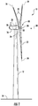
- FIG. 1 illustrates perspective view of one embodiment of a wind turbine 10 according to the present disclosure.
- the wind turbine 10 includes a tower 12 extending from a support surface 14, a nacelle 16 mounted on the tower 12, and a rotor 18 coupled to the nacelle 16.
- the rotor 18 includes a rotatable hub 20 and at least one rotor blade 22 coupled to and extending outwardly from the hub 20.
- the rotor 18 includes three rotor blades 22.
- the rotor 18 may include more or less than three rotor blades 22.
- Each rotor blade 22 may be spaced about the hub 20 to facilitate rotating the rotor 18 to enable kinetic energy to be transferred from the wind into usable mechanical energy, and subsequently, electrical energy.
- the hub 20 may be rotatably coupled to an electric generator 24 ( FIG. 2 ) positioned within the nacelle 16 to permit electrical energy to be produced.
- a generator 24 may be disposed within the nacelle 16.
- the generator 24 may be coupled to the rotor 18 of the wind turbine 10 for generating electrical power from the rotational energy generated by the rotor 18.
- the rotor 18 may include a main shaft 40 coupled to the hub 20 for rotation therewith.
- the generator 24 may then be coupled to the main shaft 40 such that rotation of the main shaft 40 drives the generator 24.
- the generator 24 includes a generator shaft 42 rotatably coupled to the main shaft 40 through a gearbox 44.
- the generator shaft 42 may be rotatably coupled directly to the main shaft 40.
- the generator 24 may be directly rotatably coupled to the main shaft 40.
- the main shaft 40 may generally be supported within the nacelle 16 by a support frame or bedplate 46 positioned atop the wind turbine tower 12.
- the main shaft 40 may be supported by the bedplate 46 via a pair of pillow blocks 48, 50 mounted to the bedplate 46.
- the wind turbine 10 may also include a turbine control system or a turbine controller 26 within the nacelle 16.
- the turbine controller 26 is disposed within a control cabinet 52 mounted to a portion of the nacelle 16.
- the turbine controller 26 may be disposed at any location on or in the wind turbine 10, at any location on the support surface 14 or generally at any other location.
- the turbine controller 26 may generally be configured to control the various operating modes (e.g., start-up or shutdown sequences) and/or components of the wind turbine 10.
- Each rotor blade 22 may also include a pitch adjustment mechanism 32 configured to rotate each rotor blade 22 about its pitch axis 34.
- each pitch adjustment mechanism 32 may include a pitch drive motor 33 (e.g., any suitable electric, hydraulic, or pneumatic motor), a pitch drive gearbox 35, and a pitch drive pinion 37.
- the pitch drive motor 33 may be coupled to the pitch drive gearbox 35 so that the pitch drive motor 33 imparts mechanical force to the pitch drive gearbox 35.
- the pitch drive gearbox 35 may be coupled to the pitch drive pinion 37 for rotation therewith.
- the pitch drive pinion 37 may, in turn, be in rotational engagement with a pitch bearing 54 coupled between the hub 20 and a corresponding rotor blade 22 such that rotation of the pitch drive pinion 37 causes rotation of the pitch bearing 54.
- rotation of the pitch drive motor 33 drives the pitch drive gearbox 35 and the pitch drive pinion 37, thereby rotating the pitch bearing 54 and the rotor blade 22 about the pitch axis 34.
- the wind turbine 10 may include one or more yaw drive mechanisms 38 communicatively coupled to the controller 26, with each yaw drive mechanism(s) 38 being configured to change the angle of the nacelle 16 relative to the wind (e.g., by engaging a yaw bearing 56 of the wind turbine 10).
- the turbine controller 26 may also be communicatively coupled to each pitch adjustment mechanism 32 of the wind turbine 10 (one of which is shown) through a separate or integral pitch controller 30 ( FIG. 1 ) for controlling and/or altering the pitch angle of the rotor blades 22 (i.e., an angle that determines a perspective of the rotor blades 22 with respect to the direction 28 of the wind).
- one or more sensors 57, 58, 59 may be provided on the wind turbine 10. More specifically, as shown, a blade sensor 57 may be configured with one or more of the rotor blades 22 to monitor the rotor blades 22. Further, as shown, a wind sensor 58 may be provided on the wind turbine 10. For example, the wind sensor 58 may a wind vane, and anemometer, a LIDAR sensor, or another suitable sensor that measures wind speed and/or direction. In addition, a pitch sensor 59 may be configured with each of the pitch drive mechanism 32, e.g. with one or more batteries of the pitch drive motors 33 thereof, which will be discussed in more detail below.
- the sensors 57, 58, 59 may further be in communication with the controller 26, and may provide related information to the controller 26.
- the pitch sensor(s) 59 may correspond to temperature sensors that send temperature signals to the controllers 26, 30 to indicate an actual temperature of the pitch batteries, which is described in more detail herein.
- the term "monitor" and variations thereof indicates that the various sensors of the wind turbine 10 may be configured to provide a direct measurement of the parameters being monitored and/or an indirect measurement of such parameters.
- the sensors described herein may, for example, be used to generate signals relating to the parameter being monitored, which can then be utilized by the controller 26 to determine the condition.
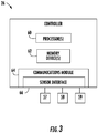
- the controller 26 may include one or more processor(s) 60 and associated memory device(s) 62 configured to perform a variety of computer-implemented functions (e.g., performing the methods, steps, calculations and the like and storing relevant data as disclosed herein). Additionally, the controller 26 may also include a communications module 64 to facilitate communications between the controller 26 and the various components of the wind turbine 10.
- the communications module 64 may include a sensor interface 66 (e.g., one or more analog-to-digital converters) to permit signals transmitted from one or more sensors 57, 58, 59 to be converted into signals that can be understood and processed by the processors 60.
- the sensors 57, 58, 59 may be communicatively coupled to the communications module 64 using any suitable means.
- the sensors 57, 58, 59 are coupled to the sensor interface 66 via a wired connection.
- the sensors 57, 58, 59 may be coupled to the sensor interface 66 via a wireless connection, such as by using any suitable wireless communications protocol known in the art.
- the term "processor” refers not only to integrated circuits referred to in the art as being included in a computer, but also refers to a controller, a microcontroller, a microcomputer, a programmable logic controller (PLC), an application specific integrated circuit, and other programmable circuits.
- the memory device(s) 62 may generally comprise memory element(s) including, but not limited to, computer readable medium (e.g., random access memory (RAM)), computer readable non-volatile medium (e.g., a flash memory), a floppy disk, a compact disc-read only memory (CD-ROM), a magneto-optical disk (MOD), a digital versatile disc (DVD) and/or other suitable memory elements.
- RAM random access memory
- CD-ROM compact disc-read only memory
- MOD magneto-optical disk
- DVD digital versatile disc
- Such memory device(s) 62 may generally be configured to store suitable computer-readable instructions that, when implemented by the processor(s) 60, configure the controller 26 to perform various functions including, but not limited to, transmitting suitable control signals to implement corrective action(s) in response to a distance signal exceeding a predetermined threshold as described herein, as well as various other suitable computer-implemented functions.
- the pitch system 70 may include a plurality of pitch drive mechanisms 32, i.e. one for each pitch axis 34. Further, as shown, each of the pitch drive mechanisms may be communicatively coupled to the power grid 45 as well as one or more backup batteries 72. More specifically, as shown, each pitch drive mechanism 32 may be associated with a plurality of backup batteries 72 that are stored in a battery cabinet 74. Thus, in certain embodiments, the battery cabinets 74 may be thermally isolated containers.
- the pitch drive motors 33 are driven by the power grid 45. However, in some instances, such as during an adverse grid event or grid loss, the pitch drive motors 33 may be driven by one or more backup batteries 72. If pitching of the rotor blades 22 relies on such batteries 72 (i.e. due to a grid loss), it is important to ensure that the batteries 72 are capable of operating when needed.
- the turbine controller 26 or pitch controller 30 is configured to implement a control strategy to estimate the consumed battery life of one or more of the batteries 72 of the pitch drive mechanisms 32 so as to reduce damaging loads from occurring during an adverse grid event of a wind turbine 10 or any other scenarios where battery power is used to pitch the rotor blades 22.
- the method 100 includes monitoring, via at least one sensor (e.g. one of the pitch sensors 59), an actual temperature of the battery 72 over a predetermined time period. More specifically, in one embodiment, the monitored temperature of the battery(ies) 72 may correspond to a cabinet temperature of the associated battery cabinet 74. As shown at 104, the method 100 also includes storing the monitored actual temperatures of the battery 72 during the predetermined time period, e.g. in the memory devices 62 of the turbine controller 26.
- the internal battery temperature will lag the measured temperature in the battery cabinet 74.
- the stored temperatures may be calibrated using a thermal model of the battery cabinet 74 and associated battery 72. This calibration can be made either in real time (before 104) or performed later prior to calculating the consumed life of the battery (i.e. after 104 but before 106).
- the method 100 includes determining the consumed battery life as a function of the monitored actual temperatures via the turbine controller 26.
- the controller 26 may be configured to determine the consumed battery life using an Arrhenius equation.
- an Arrhenius equation generally refers to a formula for the temperature dependence of reaction rates.
- the Arrhenius equation provides the dependence of the rate constant of a chemical reaction on the absolute temperature, a pre-exponential factor and other constants of the reaction. Additionally, an acceleration factor (AF) can be derived from the Arrhenius equation in order to obtain the variation of the consumed battery life for any battery temperature with respect to a reference temperature.
- AF acceleration factor
- the method 100 may include averaging a subset of the monitored actual temperatures for predetermined time intervals to obtain an average temperature.
- the controller 26 can then determine the consumed battery life as a function of the average temperature.
- the predetermined time intervals may include any suitable time period, for example, ranging from about five (5) minutes to about twenty (20) minutes, e.g. such as about ten (10) minutes. In additional embodiments, the predetermined time intervals may be less than 5 minutes or greater than 20 minutes.
- the controller 26 may be configured to generate an alarm signal, such as a software alarm in the SCADA system.
- an alarm signal such as a software alarm in the SCADA system.
- maintenance manuals for the batteries 72 may be modified such that battery replacement in all and/or a single axis could be completed when the alarm signal is generated. As such, the issue of the battery life being dependent on site temperature is effectively eliminated.
- the predetermined threshold as described herein may correspond to 80% or greater of a total battery life of the batteries 72. It should be understood, however, the predetermined threshold may also be set to be less than 80% of the total battery life of the battery 72. Accordingly, setting a minimum threshold for battery life can be useful in order to set a minimum pitch rate in case of grid loss.
- the present disclosure ensures all batteries 72 have more than the predetermined threshold of life left (e.g. more than 20%); therefore, the probability of having a pitch rate below a certain minimum rate (e.g. 3°/s) is also low, thereby reducing the loads for this scenario. As such, the present disclosure prevents the rotor blades 22 from becoming stuck in the instance of a grid loss.
- the method 100 may also include replacing the battery 72 if the consumed battery life exceeds the predetermined threshold.
- the method 100 may also include replacing all of the batteries 72 in the battery cabinet 74 if the consumed battery life of one of the batteries 72 therein exceeds the predetermined threshold.
- the method 100 may include replacing additional batteries 72 of pitch drive mechanisms 32 of adjacent rotor blades 22 if the consumed battery life of one of the batteries 72 in one of the battery cabinets 74 exceeds the predetermined threshold.
- all of the batteries 72 in an axis could be replaced at the same time to save time and costs associated with maintenance of such batteries 72.
- the controller 26 may be configured to calculate the battery life left per axis using, e.g. three separate equations. Such an embodiment may be beneficial in cases where batteries 72 were replaced due to other failure modes other than wear out.
- the method 200 includes monitoring an actual temperature of at least one battery 72 of a pitch drive mechanism 32 of a rotor blade 22 of the wind turbine 10 over a predetermined time period, e.g. via at least one sensor 59.
- the method 200 includes storing the monitored actual temperatures of the battery 72 during the predetermined time period via the turbine controller 26, e.g. in the memory device(s) 62.
- the controller 26 determines the consumed battery life as a function of the monitored actual temperatures.
- the method 200 includes replacing the battery 72 if the consumed battery life exceeds a predetermined threshold.
Landscapes
- Engineering & Computer Science (AREA)
- Life Sciences & Earth Sciences (AREA)
- Chemical & Material Sciences (AREA)
- Sustainable Development (AREA)
- Sustainable Energy (AREA)
- Combustion & Propulsion (AREA)
- Mechanical Engineering (AREA)
- General Engineering & Computer Science (AREA)
- Physics & Mathematics (AREA)
- Fluid Mechanics (AREA)
- Health & Medical Sciences (AREA)
- Analytical Chemistry (AREA)
- Biochemistry (AREA)
- General Health & Medical Sciences (AREA)
- General Physics & Mathematics (AREA)
- Immunology (AREA)
- Pathology (AREA)
- Wind Motors (AREA)
Abstract
Description
- The present disclosure relates generally to wind turbines, and more particularly to systems and methods for estimating the consumed battery life of a pitch system of a wind turbine based on temperature.
- Wind power is considered one of the cleanest, most environmentally friendly energy sources presently available, and wind turbines have gained increased attention in this regard. A modem wind turbine typically includes a tower, a generator, a gearbox, a nacelle, and a rotor including one or more rotor blades. The rotor blades capture kinetic energy from wind using known foil principles and transmit the kinetic energy through rotational energy to turn a shaft coupling the rotor blades to a gearbox, or if a gearbox is not used, directly to the generator. The generator then converts the mechanical energy to electrical energy that may be deployed to a utility grid.
- During operation, the direction of the wind which powers the wind turbine may change. The wind turbine may thus adjust the nacelle through, for example, a yaw adjustment about a longitudinal axis of the tower to maintain alignment with the wind direction. In addition, the wind turbine may adjust a pitch angle of one or more of the rotor blades via a pitch drive mechanism configured with a pitch bearing to change the angle of the blades with respect to the wind.
- Typical pitch drive mechanisms include pitch drive motor, a pitch drive gearbox, and a pitch drive pinion. In such configurations, the pitch drive motor is coupled to the pitch drive gearbox so that the pitch drive motor imparts mechanical force to the pitch drive gearbox. Similarly, the pitch drive gearbox may be coupled to the pitch drive pinion for rotation therewith. The pitch drive pinion may, in turn, be in rotational engagement with the pitch bearing coupled between the hub and a corresponding rotor blade such that rotation of the pitch drive pinion causes rotation of the pitch bearing. Thus, in such embodiments, rotation of the pitch drive motor drives the pitch drive gearbox and the pitch drive pinion, thereby rotating the pitch bearing and the rotor blade about the pitch axis.
- During normal operation, the pitch drive motors are driven by the power grid. However, in some instances, such as during an adverse grid event, the pitch drive motors may be driven by one or more backup batteries. If pitching of the blades relies on such batteries (i.e. due to a grid loss), it is important to ensure that the batteries are capable of operating when needed. Overtime, however, the motor batteries of the pitch drive mechanisms lose their charge and eventually die. Thus, if such batteries die without notice, the rotor blade associated with the dead batteries may become stuck since there is no power available to pitch the blade. In such instances, loads may increase on the stuck rotor blade, thereby causing damage thereto.
- As such, a predictive maintenance system and method that addresses the aforementioned issues would be desired. Accordingly, the present disclosure is directed to systems and methods for estimating the consumed battery life of the pitch system of the wind turbine based on temperature.
- Aspects and advantages of the invention will be set forth in part in the following description, or may be obvious from the description, or may be learned through practice of the invention.
- In one aspect, the present disclosure is directed to a method for estimating consumed battery life of at least one battery of a pitch drive mechanism of a rotor blade of a wind turbine. The method includes monitoring, via at least one sensor, an actual temperature of the battery over a predetermined time period. The method also includes storing, via a turbine controller, the monitored actual temperatures of the battery during the predetermined time period. Further, the method includes determining, via the turbine controller, the consumed battery life as a function of the monitored actual temperatures.
- In one embodiment, the battery may be stored in a battery cabinet. In such embodiments, the temperature of the battery may correspond to a cabinet temperature of the battery cabinet. Since the battery has a thermal time constant, the internal battery temperature will lag the measured temperature in the battery cabinet. Thus, the method may also include calibrating the monitored actual temperatures using a thermal model of the battery cabinet and the battery to improve accuracy. In such embodiments, the calibration can be made either in real time or performed later prior to calculating the consumed life of the battery.
- In another embodiment, the step of determining the consumed battery life as a function of the monitored temperature may include determining the consumed battery life using an Arrhenius equation.
- In further embodiments, the method may include averaging a subset of the monitored actual temperatures for predetermined time intervals to obtain an average temperature and determining the consumed battery life as a function of the average temperature. More specifically, in certain embodiments, the predetermined time intervals may range from about five (5) minutes to about twenty (20) minutes, e.g. such as about ten (10) minutes.
- In several embodiments, the method may further include generating, via the turbine controller, an alarm signal if the consumed battery life exceeds a predetermined threshold. For example, in one embodiment, the predetermined threshold may correspond to 80% or greater of a total battery life of the battery. As such, the method may further include replacing the battery if the consumed battery life exceeds the predetermined threshold.
- In yet another embodiment, the battery cabinet may contain a plurality of batteries stored therein. In such embodiments, the method may further include replacing all of the plurality of batteries in the battery cabinet if the consumed battery life exceeds the predetermined threshold.
- In still further embodiments, the method may also include replacing additional batteries of pitch drive mechanisms of adjacent rotor blades if the consumed battery life exceeds the predetermined threshold.
- In another aspect, the present disclosure is directed to a system for estimating consumed battery life of at least one battery of a pitch drive mechanism of a rotor blade of a wind turbine. The system includes at least one sensor configured for monitoring an actual temperature of the battery over a predetermined time period and a controller communicatively coupled to the at least one sensor. The controller includes at least one processor configured to perform one or more operations, including but not limited to storing the monitored actual temperatures of the battery during the predetermined time period and determining the consumed battery life as a function of the monitored actual temperatures.
- In one embodiment, the battery (or batteries) may be stored in a thermally-isolated battery cabinet. In such embodiments, the monitored temperature of the battery may correspond to a cabinet temperature of the battery cabinet. It should also be understood that the system may further include any of the additional features and/or steps as described herein.
- In yet another aspect, the present disclosure is directed to a method for preventing damaging loads from occurring during an adverse grid event of a wind turbine. The method includes monitoring, via at least one sensor, an actual temperature of at least one battery of a pitch drive mechanism of a rotor blade of the wind turbine over a predetermined time period. Another step includes storing, via a turbine controller, the monitored actual temperatures of the battery during the predetermined time period. The method also includes determining, via the turbine controller, the consumed battery life as a function of the monitored actual temperatures. Further, the method includes replacing the battery if the consumed battery life exceeds a predetermined threshold. It should also be understood that the method may further include any of the additional features and/or steps as described herein.
- These and other features, aspects and advantages of the present invention will become better understood with reference to the following description and appended claims. The accompanying drawings, which are incorporated in and constitute a part of this specification, illustrate embodiments of the invention and, together with the description, serve to explain the principles of the invention.
- A full and enabling disclosure of the present invention, including the best mode thereof, directed to one of ordinary skill in the art, is set forth in the specification, which makes reference to the appended figures, in which:
-
FIG. 1 illustrates a perspective view of a wind turbine according to one embodiment of the present disclosure; -
FIG. 2 illustrates a perspective, internal view of a nacelle of a wind turbine according to one embodiment of the present disclosure; -
FIG. 3 illustrates a schematic diagram of one embodiment of suitable components that may be included in a wind turbine controller according to the present disclosure; -
FIG. 4 illustrates a schematic diagram of one embodiment of a pitch system of a wind turbine according to the present disclosure; -
FIG. 5 illustrates a flow diagram of one embodiment of a method for estimating consumed battery life of at least one battery of a pitch drive mechanism of a rotor blade of a wind turbine according to the present disclosure; and -
FIG. 6 illustrates a flow diagram of one embodiment of a method for preventing damaging loads from occurring during an adverse grid event of a wind turbine according to the present disclosure. - Reference now will be made in detail to embodiments of the invention, one or more examples of which are illustrated in the drawings. Each example is provided by way of explanation of the invention, not limitation of the invention. In fact, it will be apparent to those skilled in the art that various modifications and variations can be made in the present invention without departing from the scope or spirit of the invention. For instance, features illustrated or described as part of one embodiment can be used with another embodiment to yield a still further embodiment. Thus, it is intended that the present invention covers such modifications and variations as come within the scope of the appended claims and their equivalents.
- Referring now to the drawings,
FIG. 1 illustrates perspective view of one embodiment of awind turbine 10 according to the present disclosure. As shown, thewind turbine 10 includes atower 12 extending from asupport surface 14, anacelle 16 mounted on thetower 12, and arotor 18 coupled to thenacelle 16. Therotor 18 includes arotatable hub 20 and at least onerotor blade 22 coupled to and extending outwardly from thehub 20. For example, in the illustrated embodiment, therotor 18 includes threerotor blades 22. However, in an alternative embodiment, therotor 18 may include more or less than threerotor blades 22. Eachrotor blade 22 may be spaced about thehub 20 to facilitate rotating therotor 18 to enable kinetic energy to be transferred from the wind into usable mechanical energy, and subsequently, electrical energy. For instance, thehub 20 may be rotatably coupled to an electric generator 24 (FIG. 2 ) positioned within thenacelle 16 to permit electrical energy to be produced. - Referring now to
FIG. 2 , a simplified, internal view of one embodiment of thenacelle 16 of thewind turbine 10 is illustrated. As shown, agenerator 24 may be disposed within thenacelle 16. In general, thegenerator 24 may be coupled to therotor 18 of thewind turbine 10 for generating electrical power from the rotational energy generated by therotor 18. For example, therotor 18 may include amain shaft 40 coupled to thehub 20 for rotation therewith. Thegenerator 24 may then be coupled to themain shaft 40 such that rotation of themain shaft 40 drives thegenerator 24. For instance, in the illustrated embodiment, thegenerator 24 includes agenerator shaft 42 rotatably coupled to themain shaft 40 through agearbox 44. However, in other embodiments, it should be appreciated that thegenerator shaft 42 may be rotatably coupled directly to themain shaft 40. Alternatively, thegenerator 24 may be directly rotatably coupled to themain shaft 40. - It should be appreciated that the
main shaft 40 may generally be supported within thenacelle 16 by a support frame orbedplate 46 positioned atop thewind turbine tower 12. For example, themain shaft 40 may be supported by thebedplate 46 via a pair of pillow blocks 48, 50 mounted to thebedplate 46. - As shown in
FIGS. 1 and2 , thewind turbine 10 may also include a turbine control system or aturbine controller 26 within thenacelle 16. For example, as shown inFIG. 2 , theturbine controller 26 is disposed within acontrol cabinet 52 mounted to a portion of thenacelle 16. However, it should be appreciated that theturbine controller 26 may be disposed at any location on or in thewind turbine 10, at any location on thesupport surface 14 or generally at any other location. Theturbine controller 26 may generally be configured to control the various operating modes (e.g., start-up or shutdown sequences) and/or components of thewind turbine 10. - Each
rotor blade 22 may also include apitch adjustment mechanism 32 configured to rotate eachrotor blade 22 about itspitch axis 34. Further, eachpitch adjustment mechanism 32 may include a pitch drive motor 33 (e.g., any suitable electric, hydraulic, or pneumatic motor), apitch drive gearbox 35, and apitch drive pinion 37. In such embodiments, thepitch drive motor 33 may be coupled to thepitch drive gearbox 35 so that thepitch drive motor 33 imparts mechanical force to thepitch drive gearbox 35. Similarly, thepitch drive gearbox 35 may be coupled to thepitch drive pinion 37 for rotation therewith. Thepitch drive pinion 37 may, in turn, be in rotational engagement with a pitch bearing 54 coupled between thehub 20 and acorresponding rotor blade 22 such that rotation of thepitch drive pinion 37 causes rotation of thepitch bearing 54. Thus, in such embodiments, rotation of thepitch drive motor 33 drives thepitch drive gearbox 35 and thepitch drive pinion 37, thereby rotating the pitch bearing 54 and therotor blade 22 about thepitch axis 34. Similarly, thewind turbine 10 may include one or moreyaw drive mechanisms 38 communicatively coupled to thecontroller 26, with each yaw drive mechanism(s) 38 being configured to change the angle of thenacelle 16 relative to the wind (e.g., by engaging a yaw bearing 56 of the wind turbine 10). - Further, the
turbine controller 26 may also be communicatively coupled to eachpitch adjustment mechanism 32 of the wind turbine 10 (one of which is shown) through a separate or integral pitch controller 30 (FIG. 1 ) for controlling and/or altering the pitch angle of the rotor blades 22 (i.e., an angle that determines a perspective of therotor blades 22 with respect to thedirection 28 of the wind). - In addition, as shown in
FIG. 2 , one ormore sensors wind turbine 10. More specifically, as shown, ablade sensor 57 may be configured with one or more of therotor blades 22 to monitor therotor blades 22. Further, as shown, awind sensor 58 may be provided on thewind turbine 10. For example, thewind sensor 58 may a wind vane, and anemometer, a LIDAR sensor, or another suitable sensor that measures wind speed and/or direction. In addition, apitch sensor 59 may be configured with each of thepitch drive mechanism 32, e.g. with one or more batteries of thepitch drive motors 33 thereof, which will be discussed in more detail below. As such, thesensors controller 26, and may provide related information to thecontroller 26. For example, the pitch sensor(s) 59 may correspond to temperature sensors that send temperature signals to thecontrollers - It should also be appreciated that, as used herein, the term "monitor" and variations thereof indicates that the various sensors of the
wind turbine 10 may be configured to provide a direct measurement of the parameters being monitored and/or an indirect measurement of such parameters. Thus, the sensors described herein may, for example, be used to generate signals relating to the parameter being monitored, which can then be utilized by thecontroller 26 to determine the condition. - Referring now to
FIG. 3 , there is illustrated a block diagram of one embodiment of suitable components that may be included within thecontroller 26 according to the present disclosure. As shown, thecontroller 26 may include one or more processor(s) 60 and associated memory device(s) 62 configured to perform a variety of computer-implemented functions (e.g., performing the methods, steps, calculations and the like and storing relevant data as disclosed herein). Additionally, thecontroller 26 may also include acommunications module 64 to facilitate communications between thecontroller 26 and the various components of thewind turbine 10. Further, thecommunications module 64 may include a sensor interface 66 (e.g., one or more analog-to-digital converters) to permit signals transmitted from one ormore sensors processors 60. It should be appreciated that thesensors communications module 64 using any suitable means. For example, as shown inFIG. 3 , thesensors sensor interface 66 via a wired connection. However, in other embodiments, thesensors sensor interface 66 via a wireless connection, such as by using any suitable wireless communications protocol known in the art. - As used herein, the term "processor" refers not only to integrated circuits referred to in the art as being included in a computer, but also refers to a controller, a microcontroller, a microcomputer, a programmable logic controller (PLC), an application specific integrated circuit, and other programmable circuits. Additionally, the memory device(s) 62 may generally comprise memory element(s) including, but not limited to, computer readable medium (e.g., random access memory (RAM)), computer readable non-volatile medium (e.g., a flash memory), a floppy disk, a compact disc-read only memory (CD-ROM), a magneto-optical disk (MOD), a digital versatile disc (DVD) and/or other suitable memory elements. Such memory device(s) 62 may generally be configured to store suitable computer-readable instructions that, when implemented by the processor(s) 60, configure the
controller 26 to perform various functions including, but not limited to, transmitting suitable control signals to implement corrective action(s) in response to a distance signal exceeding a predetermined threshold as described herein, as well as various other suitable computer-implemented functions. - Referring now to
FIG. 4 , a schematic diagram of one embodiment anoverall pitch system 70 for thewind turbine 10 is illustrated. More specifically, as shown, thepitch system 70 may include a plurality ofpitch drive mechanisms 32, i.e. one for eachpitch axis 34. Further, as shown, each of the pitch drive mechanisms may be communicatively coupled to thepower grid 45 as well as one or morebackup batteries 72. More specifically, as shown, eachpitch drive mechanism 32 may be associated with a plurality ofbackup batteries 72 that are stored in abattery cabinet 74. Thus, in certain embodiments, thebattery cabinets 74 may be thermally isolated containers. - During normal operation of the
wind turbine 10, thepitch drive motors 33 are driven by thepower grid 45. However, in some instances, such as during an adverse grid event or grid loss, thepitch drive motors 33 may be driven by one or morebackup batteries 72. If pitching of therotor blades 22 relies on such batteries 72 (i.e. due to a grid loss), it is important to ensure that thebatteries 72 are capable of operating when needed. Thus, the turbine controller 26 (or pitch controller 30) is configured to implement a control strategy to estimate the consumed battery life of one or more of thebatteries 72 of thepitch drive mechanisms 32 so as to reduce damaging loads from occurring during an adverse grid event of awind turbine 10 or any other scenarios where battery power is used to pitch therotor blades 22. - More specifically, as shown in
FIG. 5 , a flow diagram of one embodiment of amethod 100 for estimating consumed battery life of at least onebattery 72 of thepitch drive mechanism 32 is illustrated. As shown at 102, themethod 100 includes monitoring, via at least one sensor (e.g. one of the pitch sensors 59), an actual temperature of thebattery 72 over a predetermined time period. More specifically, in one embodiment, the monitored temperature of the battery(ies) 72 may correspond to a cabinet temperature of the associatedbattery cabinet 74. As shown at 104, themethod 100 also includes storing the monitored actual temperatures of thebattery 72 during the predetermined time period, e.g. in thememory devices 62 of theturbine controller 26. - Since the
battery 72 has a thermal time constant, the internal battery temperature will lag the measured temperature in thebattery cabinet 74. To improve accuracy, the stored temperatures may be calibrated using a thermal model of thebattery cabinet 74 and associatedbattery 72. This calibration can be made either in real time (before 104) or performed later prior to calculating the consumed life of the battery (i.e. after 104 but before 106). - As shown at 106, the
method 100 includes determining the consumed battery life as a function of the monitored actual temperatures via theturbine controller 26. For example, in one embodiment, thecontroller 26 may be configured to determine the consumed battery life using an Arrhenius equation. As used herein, an Arrhenius equation generally refers to a formula for the temperature dependence of reaction rates. For example, in one embodiment, the Arrhenius equation may be represented by Equation (1) below:
- k is the rate constant,
- T is the absolute temperature (in kelvins),
- A is the pre-exponential factor, a constant for each chemical reaction that defines the rate due to frequency of collisions in the correct orientation,
- Ea is the activation energy for the reaction (in Joules mol-1), and
- R is the universal gas constant.
- Thus, the Arrhenius equation provides the dependence of the rate constant of a chemical reaction on the absolute temperature, a pre-exponential factor and other constants of the reaction. Additionally, an acceleration factor (AF) can be derived from the Arrhenius equation in order to obtain the variation of the consumed battery life for any battery temperature with respect to a reference temperature.
- In further embodiments, the
method 100 may include averaging a subset of the monitored actual temperatures for predetermined time intervals to obtain an average temperature. In such embodiments, thecontroller 26 can then determine the consumed battery life as a function of the average temperature. It should be understood that the predetermined time intervals may include any suitable time period, for example, ranging from about five (5) minutes to about twenty (20) minutes, e.g. such as about ten (10) minutes. In additional embodiments, the predetermined time intervals may be less than 5 minutes or greater than 20 minutes. - If the consumed battery life exceeds a predetermined threshold, the
controller 26 may be configured to generate an alarm signal, such as a software alarm in the SCADA system. In this way, maintenance manuals for thebatteries 72 may be modified such that battery replacement in all and/or a single axis could be completed when the alarm signal is generated. As such, the issue of the battery life being dependent on site temperature is effectively eliminated. - In one embodiment, the predetermined threshold as described herein may correspond to 80% or greater of a total battery life of the
batteries 72. It should be understood, however, the predetermined threshold may also be set to be less than 80% of the total battery life of thebattery 72. Accordingly, setting a minimum threshold for battery life can be useful in order to set a minimum pitch rate in case of grid loss. In other words, the present disclosure ensures allbatteries 72 have more than the predetermined threshold of life left (e.g. more than 20%); therefore, the probability of having a pitch rate below a certain minimum rate (e.g. 3°/s) is also low, thereby reducing the loads for this scenario. As such, the present disclosure prevents therotor blades 22 from becoming stuck in the instance of a grid loss. - Accordingly, the
method 100 may also include replacing thebattery 72 if the consumed battery life exceeds the predetermined threshold. In such embodiments, themethod 100 may also include replacing all of thebatteries 72 in thebattery cabinet 74 if the consumed battery life of one of thebatteries 72 therein exceeds the predetermined threshold. In addition, themethod 100 may include replacingadditional batteries 72 ofpitch drive mechanisms 32 ofadjacent rotor blades 22 if the consumed battery life of one of thebatteries 72 in one of thebattery cabinets 74 exceeds the predetermined threshold. In other words, for certain embodiments, all of thebatteries 72 in an axis could be replaced at the same time to save time and costs associated with maintenance ofsuch batteries 72. Alternatively, if all ofbatteries 72 for the axes were not replaced, thecontroller 26 may be configured to calculate the battery life left per axis using, e.g. three separate equations. Such an embodiment may be beneficial in cases wherebatteries 72 were replaced due to other failure modes other than wear out. - Referring now to
FIG. 6 , a flow diagram of one embodiment of amethod 200 for preventing damaging loads from occurring during an adverse grid event of awind turbine 10 is illustrated. As shown at 202, themethod 200 includes monitoring an actual temperature of at least onebattery 72 of apitch drive mechanism 32 of arotor blade 22 of thewind turbine 10 over a predetermined time period, e.g. via at least onesensor 59. As shown at 204, themethod 200 includes storing the monitored actual temperatures of thebattery 72 during the predetermined time period via theturbine controller 26, e.g. in the memory device(s) 62. As shown at 206, thecontroller 26 then determines the consumed battery life as a function of the monitored actual temperatures. Thus, as shown at 208, themethod 200 includes replacing thebattery 72 if the consumed battery life exceeds a predetermined threshold. - This written description uses examples to disclose the invention, including the best mode, and also to enable any person skilled in the art to practice the invention, including making and using any devices or systems and performing any incorporated methods. The patentable scope of the invention is defined by the claims, and may include other examples that occur to those skilled in the art. Such other examples are intended to be within the scope of the claims if they include structural elements that do not differ from the literal language of the claims, or if they include equivalent structural elements with insubstantial differences from the literal languages of the claims.
Reference Character Component 10 Wind Turbine 12 Tower 14 Surface 16 Nacelle 18 Rotor 20 Rotatable Hub 22 Rotor Blade 24 Generator 26 Turbine Controller 28 Direction 32 Pitch Drive Mechanism 33 Pitch Drive Motor 34 Pitch Axes 35 Pitch Drive Gearbox 36 Yaw Axis 37 Pitch Drive Pinion 38 Yaw Drive Mechanism 40 Main Shaft 42 Generator Shaft 44 Gearbox 45 Power Grid 46 Bedplate 48 Pillow blocks 50 Pillow Blocks 52 Control Cabinet 54 Pitch Bearing 56 Yaw Bearing 57 Sensor 58 Sensor 59 Sensor 60 Processor(s) 62 Memory Device(s) 64 Communications Module 66 Sensor Interface 70 System 72 Batteries 74 Battery Cabinet 100 Method 102 Method Step 104 Method Step 106 Method Step 200 Method 202 Method Step 204 Method Step 206 Method Step 208 Method Step
Claims (20)
- A method for estimating consumed battery life of at least one battery of a pitch drive mechanism of a rotor blade of a wind turbine, the method comprising:monitoring, via at least one sensor, an actual temperature of the battery over a predetermined time period;storing, via a turbine controller, the monitored actual temperatures of the battery during the predetermined time period; and,determining, via the turbine controller, the consumed battery life as a function of the monitored actual temperatures.
- The method of claim 1, wherein the battery is stored in a battery cabinet, the actual temperature of the battery corresponding to a cabinet temperature of the battery cabinet.
- The method of claim 2, further comprising calibrating the monitored actual temperatures using a thermal model of the battery cabinet and the battery.
- The method of claim 1, wherein determining, via the turbine controller, the consumed battery life as a function of the monitored actual temperature further comprises determining the consumed battery life using an Arrhenius equation.
- The method of claim 1, further comprising:averaging a subset of the monitored actual temperatures for predetermined time intervals to obtain an average temperature; and,determining the consumed battery life as a function of the average temperature.
- The method of claim 2, further comprising generating, via the turbine controller, an alarm signal if the consumed battery life exceeds a predetermined threshold.
- The method of claim 6, wherein the predetermined threshold comprises 80% or greater of a total battery life of the battery.
- The method of claim 6, further comprising replacing the battery if the consumed battery life exceeds the predetermined threshold.
- The method of claim 6, wherein the battery cabinet comprises a plurality of batteries stored therein, the method further comprising replacing all of the plurality of batteries in the battery cabinet if the consumed battery life exceeds the predetermined threshold.
- The method of claim 6, further comprising replacing additional batteries of pitch drive mechanisms of adjacent rotor blades if the consumed battery life exceeds the predetermined threshold.
- A system for estimating consumed battery life of at least one battery of a pitch drive mechanism of a rotor blade of a wind turbine, the system comprising:at least one sensor configured for monitoring an actual temperature of the battery over a predetermined time period;a controller communicatively coupled to the at least one sensor, the controller comprising at least one processor configured to perform one or more operations, the one or more operations comprising:storing the monitored actual temperatures of the battery during the predetermined time period; and,determining the consumed battery life as a function of the monitored actual temperatures.
- The system of claim 11, wherein the battery is stored in a thermally-isolated battery cabinet, the temperature of the battery corresponding to a cabinet temperature of the battery cabinet.
- The system of claim 11, wherein determining the consumed battery life as a function of the monitored temperature further comprises determining the consumed battery life using an Arrhenius equation.
- The system of claim 11, wherein the one or more operations further comprise:averaging a subset of the monitored actual temperatures for predetermined time intervals to obtain an average temperature; and,determining the consumed battery life as a function of the average temperature.
- The system of claim 12, wherein the one or more operations further comprise:generating an alarm signal if the consumed battery life exceeds a predetermined threshold.
- The system of claim 15, wherein the predetermined threshold comprises 80% or greater of a total battery life of the battery.
- The system of claim 15, wherein the one or more operations further comprise:replacing the battery if the consumed battery life exceeds the predetermined threshold.
- The system of claim 15, wherein the battery cabinet comprises a plurality of batteries stored therein, and wherein the one or more operations further comprise:replacing all of the plurality of batteries within the battery cabinet if the consumed battery life exceeds the predetermined threshold.
- A method for preventing damaging loads from occurring during an adverse grid event of a wind turbine, the method comprising:monitoring, via at least one sensor, an actual temperature of at least one battery of a pitch drive mechanism of a rotor blade of the wind turbine over a predetermined time period;storing, via a turbine controller, the monitored actual temperatures of the battery during the predetermined time period;determining, via the turbine controller, the consumed battery life as a function of the monitored actual temperatures; and,replacing the battery if the consumed battery life exceeds a predetermined threshold.
- The method of claim 19, further comprising replacing additional batteries of pitch drive mechanisms of adjacent rotor blades if the consumed battery life exceeds the predetermined threshold.
Priority Applications (4)
| Application Number | Priority Date | Filing Date | Title |
|---|---|---|---|
| DK17382298.2T DK3406893T3 (en) | 2017-05-25 | 2017-05-25 | SYSTEM AND METHOD FOR ESTIMATING BATTERY LIFE EXPENDED BY A PITCH SYSTEM OF A WIND MILL |
| EP17382298.2A EP3406893B1 (en) | 2017-05-25 | 2017-05-25 | System and method for estimating consumed battery life of a pitch system of a wind turbine |
| ES17382298T ES3046182T3 (en) | 2017-05-25 | 2017-05-25 | System and method for estimating consumed battery life of a pitch system of a wind turbine |
| US15/976,914 US10738767B2 (en) | 2017-05-25 | 2018-05-11 | System and method for estimating consumed battery life of a pitch system of a wind turbine |
Applications Claiming Priority (1)
| Application Number | Priority Date | Filing Date | Title |
|---|---|---|---|
| EP17382298.2A EP3406893B1 (en) | 2017-05-25 | 2017-05-25 | System and method for estimating consumed battery life of a pitch system of a wind turbine |
Publications (2)
| Publication Number | Publication Date |
|---|---|
| EP3406893A1 true EP3406893A1 (en) | 2018-11-28 |
| EP3406893B1 EP3406893B1 (en) | 2025-07-23 |
Family
ID=59077988
Family Applications (1)
| Application Number | Title | Priority Date | Filing Date |
|---|---|---|---|
| EP17382298.2A Active EP3406893B1 (en) | 2017-05-25 | 2017-05-25 | System and method for estimating consumed battery life of a pitch system of a wind turbine |
Country Status (4)
| Country | Link |
|---|---|
| US (1) | US10738767B2 (en) |
| EP (1) | EP3406893B1 (en) |
| DK (1) | DK3406893T3 (en) |
| ES (1) | ES3046182T3 (en) |
Cited By (2)
| Publication number | Priority date | Publication date | Assignee | Title |
|---|---|---|---|---|
| CN111997843A (en) * | 2020-08-26 | 2020-11-27 | 中车青岛四方车辆研究所有限公司 | Backup power supply life health monitoring method and monitoring system |
| EP3796016A1 (en) * | 2019-09-09 | 2021-03-24 | General Electric Company | System and method for detecting battery faults in a pitch system of a wind turbine |
Families Citing this family (2)
| Publication number | Priority date | Publication date | Assignee | Title |
|---|---|---|---|---|
| CN109611272A (en) * | 2018-12-29 | 2019-04-12 | 固安华电天仁控制设备有限公司 | It is a kind of easily to replace without box variable blade control system |
| US11879425B2 (en) * | 2021-12-08 | 2024-01-23 | Ge Infrastructure Technology Llc | System and method for controlling blade pitch of wind turbine rotor blades in an idling state of the rotor hub |
Citations (3)
| Publication number | Priority date | Publication date | Assignee | Title |
|---|---|---|---|---|
| US6014012A (en) * | 1998-07-28 | 2000-01-11 | Ntt Power And Building Facilities Inc. | Apparatus for managing a battery unit having storage batteries |
| US20140257751A1 (en) * | 2013-03-06 | 2014-09-11 | General Electric Company | Methods for scheduling the replacement of wind turbine batteries and related systems |
| US20160107526A1 (en) * | 2014-10-15 | 2016-04-21 | Johnson Controls Technology Company | Cooling strategy for battery systems |
Family Cites Families (1)
| Publication number | Priority date | Publication date | Assignee | Title |
|---|---|---|---|---|
| EP2501932B1 (en) * | 2009-11-17 | 2015-05-06 | SSB Wind Systems GmbH & Co. KG | Control cabinet for a wind turbine |
-
2017
- 2017-05-25 DK DK17382298.2T patent/DK3406893T3/en active
- 2017-05-25 EP EP17382298.2A patent/EP3406893B1/en active Active
- 2017-05-25 ES ES17382298T patent/ES3046182T3/en active Active
-
2018
- 2018-05-11 US US15/976,914 patent/US10738767B2/en active Active
Patent Citations (3)
| Publication number | Priority date | Publication date | Assignee | Title |
|---|---|---|---|---|
| US6014012A (en) * | 1998-07-28 | 2000-01-11 | Ntt Power And Building Facilities Inc. | Apparatus for managing a battery unit having storage batteries |
| US20140257751A1 (en) * | 2013-03-06 | 2014-09-11 | General Electric Company | Methods for scheduling the replacement of wind turbine batteries and related systems |
| US20160107526A1 (en) * | 2014-10-15 | 2016-04-21 | Johnson Controls Technology Company | Cooling strategy for battery systems |
Cited By (4)
| Publication number | Priority date | Publication date | Assignee | Title |
|---|---|---|---|---|
| EP3796016A1 (en) * | 2019-09-09 | 2021-03-24 | General Electric Company | System and method for detecting battery faults in a pitch system of a wind turbine |
| US11476685B2 (en) | 2019-09-09 | 2022-10-18 | General Electric Company | System and method for detecting battery faults in a pitch system of a wind turbine |
| CN111997843A (en) * | 2020-08-26 | 2020-11-27 | 中车青岛四方车辆研究所有限公司 | Backup power supply life health monitoring method and monitoring system |
| CN111997843B (en) * | 2020-08-26 | 2021-10-29 | 中车青岛四方车辆研究所有限公司 | Backup power supply life health monitoring method and monitoring system |
Also Published As
| Publication number | Publication date |
|---|---|
| ES3046182T3 (en) | 2025-12-01 |
| EP3406893B1 (en) | 2025-07-23 |
| DK3406893T3 (en) | 2025-10-27 |
| US20180340517A1 (en) | 2018-11-29 |
| US10738767B2 (en) | 2020-08-11 |
Similar Documents
| Publication | Publication Date | Title |
|---|---|---|
| US10830208B2 (en) | System and method for mitigating blade run-away loads in the event of a pitch system failure | |
| US11041483B2 (en) | Methods of operating a wind turbine | |
| EP3597904B1 (en) | System and method for reducing wind turbine loads by yawing the nacelle to a predetermined position based on rotor imbalance | |
| US10914290B2 (en) | System and method for testing an energy storage device of a wind turbine pitch system | |
| EP3409940A1 (en) | System and method for reducing loads during an idling or parked state of a wind turbine via yaw offset | |
| EP3597910B1 (en) | System and method for reducing loads during an idling or parked state of a wind turbine with a stuck rotor blade | |
| US10738767B2 (en) | System and method for estimating consumed battery life of a pitch system of a wind turbine | |
| EP3454067B1 (en) | Predictive battery test systems and methods | |
| EP3581795B1 (en) | System and method for controlling a wind turbine to minimize rotor blade damage | |
| EP3625528B1 (en) | System and method for estimating motor temperature of a pitch system of a wind turbine | |
| EP3796016B1 (en) | System and method for detecting battery faults in a pitch system of a wind turbine | |
| EP3788258B1 (en) | System and method for improved overspeed monitoring of a wind turbine operating at reduced rotor speeds | |
| US10876518B2 (en) | System and method for mitigating damage in a rotor blade of a wind turbine | |
| US10316822B2 (en) | System and method for improved overspeed monitoring of a wind turbine operating at reduced rotor speeds | |
| US11754039B1 (en) | Load dependent autonomous yaw control for a wind turbine | |
| EP3722597B1 (en) | System and method for preventing catastrophic damage in drivetrain of a wind turbine | |
| EP4040626A1 (en) | Systems and methods for operating a power generating asset | |
| US10697432B2 (en) | Wind farm energy storage device for curtailment and auxiliary loads use |
Legal Events
| Date | Code | Title | Description |
|---|---|---|---|
| PUAI | Public reference made under article 153(3) epc to a published international application that has entered the european phase |
Free format text: ORIGINAL CODE: 0009012 |
|
| STAA | Information on the status of an ep patent application or granted ep patent |
Free format text: STATUS: THE APPLICATION HAS BEEN PUBLISHED |
|
| AK | Designated contracting states |
Kind code of ref document: A1 Designated state(s): AL AT BE BG CH CY CZ DE DK EE ES FI FR GB GR HR HU IE IS IT LI LT LU LV MC MK MT NL NO PL PT RO RS SE SI SK SM TR |
|
| AX | Request for extension of the european patent |
Extension state: BA ME |
|
| STAA | Information on the status of an ep patent application or granted ep patent |
Free format text: STATUS: REQUEST FOR EXAMINATION WAS MADE |
|
| 17P | Request for examination filed |
Effective date: 20190528 |
|
| RBV | Designated contracting states (corrected) |
Designated state(s): AL AT BE BG CH CY CZ DE DK EE ES FI FR GB GR HR HU IE IS IT LI LT LU LV MC MK MT NL NO PL PT RO RS SE SI SK SM TR |
|
| STAA | Information on the status of an ep patent application or granted ep patent |
Free format text: STATUS: EXAMINATION IS IN PROGRESS |
|
| 17Q | First examination report despatched |
Effective date: 20220112 |
|
| P01 | Opt-out of the competence of the unified patent court (upc) registered |
Effective date: 20230530 |
|
| RAP1 | Party data changed (applicant data changed or rights of an application transferred) |
Owner name: GENERAL ELECTRIC RENOVABLES ESPANA, S.L. |
|
| GRAP | Despatch of communication of intention to grant a patent |
Free format text: ORIGINAL CODE: EPIDOSNIGR1 |
|
| STAA | Information on the status of an ep patent application or granted ep patent |
Free format text: STATUS: GRANT OF PATENT IS INTENDED |
|
| INTG | Intention to grant announced |
Effective date: 20250228 |
|
| GRAS | Grant fee paid |
Free format text: ORIGINAL CODE: EPIDOSNIGR3 |
|
| GRAA | (expected) grant |
Free format text: ORIGINAL CODE: 0009210 |
|
| STAA | Information on the status of an ep patent application or granted ep patent |
Free format text: STATUS: THE PATENT HAS BEEN GRANTED |
|
| AK | Designated contracting states |
Kind code of ref document: B1 Designated state(s): AL AT BE BG CH CY CZ DE DK EE ES FI FR GB GR HR HU IE IS IT LI LT LU LV MC MK MT NL NO PL PT RO RS SE SI SK SM TR |
|
| REG | Reference to a national code |
Ref country code: GB Ref legal event code: FG4D |
|
| REG | Reference to a national code |
Ref country code: CH Ref legal event code: EP |
|
| REG | Reference to a national code |
Ref country code: DE Ref legal event code: R096 Ref document number: 602017090724 Country of ref document: DE |
|
| REG | Reference to a national code |
Ref country code: IE Ref legal event code: FG4D |
|
| REG | Reference to a national code |
Ref country code: DK Ref legal event code: T3 Effective date: 20251022 |
|
| REG | Reference to a national code |
Ref country code: NL Ref legal event code: MP Effective date: 20250723 |
|
| REG | Reference to a national code |
Ref country code: ES Ref legal event code: FG2A Ref document number: 3046182 Country of ref document: ES Kind code of ref document: T3 Effective date: 20251201 |
|
| PG25 | Lapsed in a contracting state [announced via postgrant information from national office to epo] |
Ref country code: PT Free format text: LAPSE BECAUSE OF FAILURE TO SUBMIT A TRANSLATION OF THE DESCRIPTION OR TO PAY THE FEE WITHIN THE PRESCRIBED TIME-LIMIT Effective date: 20251124 |
|
| PG25 | Lapsed in a contracting state [announced via postgrant information from national office to epo] |
Ref country code: NL Free format text: LAPSE BECAUSE OF FAILURE TO SUBMIT A TRANSLATION OF THE DESCRIPTION OR TO PAY THE FEE WITHIN THE PRESCRIBED TIME-LIMIT Effective date: 20250723 |
|
| REG | Reference to a national code |
Ref country code: AT Ref legal event code: MK05 Ref document number: 1816641 Country of ref document: AT Kind code of ref document: T Effective date: 20250723 |
|
| PG25 | Lapsed in a contracting state [announced via postgrant information from national office to epo] |
Ref country code: IS Free format text: LAPSE BECAUSE OF FAILURE TO SUBMIT A TRANSLATION OF THE DESCRIPTION OR TO PAY THE FEE WITHIN THE PRESCRIBED TIME-LIMIT Effective date: 20251123 |
|
| PG25 | Lapsed in a contracting state [announced via postgrant information from national office to epo] |
Ref country code: NO Free format text: LAPSE BECAUSE OF FAILURE TO SUBMIT A TRANSLATION OF THE DESCRIPTION OR TO PAY THE FEE WITHIN THE PRESCRIBED TIME-LIMIT Effective date: 20251023 |
|
| REG | Reference to a national code |
Ref country code: LT Ref legal event code: MG9D |
|
| PG25 | Lapsed in a contracting state [announced via postgrant information from national office to epo] |
Ref country code: AT Free format text: LAPSE BECAUSE OF FAILURE TO SUBMIT A TRANSLATION OF THE DESCRIPTION OR TO PAY THE FEE WITHIN THE PRESCRIBED TIME-LIMIT Effective date: 20250723 |
|
| PG25 | Lapsed in a contracting state [announced via postgrant information from national office to epo] |
Ref country code: FI Free format text: LAPSE BECAUSE OF FAILURE TO SUBMIT A TRANSLATION OF THE DESCRIPTION OR TO PAY THE FEE WITHIN THE PRESCRIBED TIME-LIMIT Effective date: 20250723 |
|
| PG25 | Lapsed in a contracting state [announced via postgrant information from national office to epo] |
Ref country code: HR Free format text: LAPSE BECAUSE OF FAILURE TO SUBMIT A TRANSLATION OF THE DESCRIPTION OR TO PAY THE FEE WITHIN THE PRESCRIBED TIME-LIMIT Effective date: 20250723 |
|
| PG25 | Lapsed in a contracting state [announced via postgrant information from national office to epo] |
Ref country code: GR Free format text: LAPSE BECAUSE OF FAILURE TO SUBMIT A TRANSLATION OF THE DESCRIPTION OR TO PAY THE FEE WITHIN THE PRESCRIBED TIME-LIMIT Effective date: 20251024 |
|
| PG25 | Lapsed in a contracting state [announced via postgrant information from national office to epo] |
Ref country code: SE Free format text: LAPSE BECAUSE OF FAILURE TO SUBMIT A TRANSLATION OF THE DESCRIPTION OR TO PAY THE FEE WITHIN THE PRESCRIBED TIME-LIMIT Effective date: 20250723 |
|
| PG25 | Lapsed in a contracting state [announced via postgrant information from national office to epo] |
Ref country code: LV Free format text: LAPSE BECAUSE OF FAILURE TO SUBMIT A TRANSLATION OF THE DESCRIPTION OR TO PAY THE FEE WITHIN THE PRESCRIBED TIME-LIMIT Effective date: 20250723 |
|
| PG25 | Lapsed in a contracting state [announced via postgrant information from national office to epo] |
Ref country code: PL Free format text: LAPSE BECAUSE OF FAILURE TO SUBMIT A TRANSLATION OF THE DESCRIPTION OR TO PAY THE FEE WITHIN THE PRESCRIBED TIME-LIMIT Effective date: 20250723 Ref country code: BG Free format text: LAPSE BECAUSE OF FAILURE TO SUBMIT A TRANSLATION OF THE DESCRIPTION OR TO PAY THE FEE WITHIN THE PRESCRIBED TIME-LIMIT Effective date: 20250723 |
|
| PG25 | Lapsed in a contracting state [announced via postgrant information from national office to epo] |
Ref country code: RS Free format text: LAPSE BECAUSE OF FAILURE TO SUBMIT A TRANSLATION OF THE DESCRIPTION OR TO PAY THE FEE WITHIN THE PRESCRIBED TIME-LIMIT Effective date: 20251023 |
|
| REG | Reference to a national code |
Ref country code: CH Ref legal event code: W10 Free format text: ST27 STATUS EVENT CODE: U-0-0-W10-W00 (AS PROVIDED BY THE NATIONAL OFFICE) Effective date: 20260218 |
|
| RAP4 | Party data changed (patent owner data changed or rights of a patent transferred) |
Owner name: GE VERNOVA RENOVABLES ESPANA, S.L. |
|
| REG | Reference to a national code |
Ref country code: CH Ref legal event code: W10 Free format text: ST27 STATUS EVENT CODE: U-0-0-W10-W00 (AS PROVIDED BY THE NATIONAL OFFICE) Effective date: 20260325 |
|
| PG25 | Lapsed in a contracting state [announced via postgrant information from national office to epo] |
Ref country code: SM Free format text: LAPSE BECAUSE OF FAILURE TO SUBMIT A TRANSLATION OF THE DESCRIPTION OR TO PAY THE FEE WITHIN THE PRESCRIBED TIME-LIMIT Effective date: 20250723 |
|
| PG25 | Lapsed in a contracting state [announced via postgrant information from national office to epo] |
Ref country code: IT Free format text: LAPSE BECAUSE OF FAILURE TO SUBMIT A TRANSLATION OF THE DESCRIPTION OR TO PAY THE FEE WITHIN THE PRESCRIBED TIME-LIMIT Effective date: 20250723 |
|
| RAP4 | Party data changed (patent owner data changed or rights of a patent transferred) |
Owner name: GE VERNOVA RENOVABLES ESPANA, S.L. |
|
| PG25 | Lapsed in a contracting state [announced via postgrant information from national office to epo] |
Ref country code: CZ Free format text: LAPSE BECAUSE OF FAILURE TO SUBMIT A TRANSLATION OF THE DESCRIPTION OR TO PAY THE FEE WITHIN THE PRESCRIBED TIME-LIMIT Effective date: 20250723 |
|
| PG25 | Lapsed in a contracting state [announced via postgrant information from national office to epo] |
Ref country code: SK Free format text: LAPSE BECAUSE OF FAILURE TO SUBMIT A TRANSLATION OF THE DESCRIPTION OR TO PAY THE FEE WITHIN THE PRESCRIBED TIME-LIMIT Effective date: 20250723 Ref country code: EE Free format text: LAPSE BECAUSE OF FAILURE TO SUBMIT A TRANSLATION OF THE DESCRIPTION OR TO PAY THE FEE WITHIN THE PRESCRIBED TIME-LIMIT Effective date: 20250723 |