EP3406887A1 - Method for manufacturing a thrust reverser cascade and thrust reverser cascade - Google Patents
Method for manufacturing a thrust reverser cascade and thrust reverser cascade Download PDFInfo
- Publication number
- EP3406887A1 EP3406887A1 EP18152219.4A EP18152219A EP3406887A1 EP 3406887 A1 EP3406887 A1 EP 3406887A1 EP 18152219 A EP18152219 A EP 18152219A EP 3406887 A1 EP3406887 A1 EP 3406887A1
- Authority
- EP
- European Patent Office
- Prior art keywords
- strong back
- vane
- back member
- strip assembly
- members
- Prior art date
- Legal status (The legal status is an assumption and is not a legal conclusion. Google has not performed a legal analysis and makes no representation as to the accuracy of the status listed.)
- Granted
Links
Images


Classifications
-
- F—MECHANICAL ENGINEERING; LIGHTING; HEATING; WEAPONS; BLASTING
- F02—COMBUSTION ENGINES; HOT-GAS OR COMBUSTION-PRODUCT ENGINE PLANTS
- F02K—JET-PROPULSION PLANTS
- F02K1/00—Plants characterised by the form or arrangement of the jet pipe or nozzle; Jet pipes or nozzles peculiar thereto
- F02K1/54—Nozzles having means for reversing jet thrust
- F02K1/64—Reversing fan flow
- F02K1/70—Reversing fan flow using thrust reverser flaps or doors mounted on the fan housing
-
- F—MECHANICAL ENGINEERING; LIGHTING; HEATING; WEAPONS; BLASTING
- F02—COMBUSTION ENGINES; HOT-GAS OR COMBUSTION-PRODUCT ENGINE PLANTS
- F02K—JET-PROPULSION PLANTS
- F02K1/00—Plants characterised by the form or arrangement of the jet pipe or nozzle; Jet pipes or nozzles peculiar thereto
- F02K1/54—Nozzles having means for reversing jet thrust
- F02K1/64—Reversing fan flow
- F02K1/70—Reversing fan flow using thrust reverser flaps or doors mounted on the fan housing
- F02K1/72—Reversing fan flow using thrust reverser flaps or doors mounted on the fan housing the aft end of the fan housing being movable to uncover openings in the fan housing for the reversed flow
-
- F—MECHANICAL ENGINEERING; LIGHTING; HEATING; WEAPONS; BLASTING
- F05—INDEXING SCHEMES RELATING TO ENGINES OR PUMPS IN VARIOUS SUBCLASSES OF CLASSES F01-F04
- F05D—INDEXING SCHEME FOR ASPECTS RELATING TO NON-POSITIVE-DISPLACEMENT MACHINES OR ENGINES, GAS-TURBINES OR JET-PROPULSION PLANTS
- F05D2230/00—Manufacture
- F05D2230/50—Building or constructing in particular ways
- F05D2230/51—Building or constructing in particular ways in a modular way, e.g. using several identical or complementary parts or features
-
- F—MECHANICAL ENGINEERING; LIGHTING; HEATING; WEAPONS; BLASTING
- F05—INDEXING SCHEMES RELATING TO ENGINES OR PUMPS IN VARIOUS SUBCLASSES OF CLASSES F01-F04
- F05D—INDEXING SCHEME FOR ASPECTS RELATING TO NON-POSITIVE-DISPLACEMENT MACHINES OR ENGINES, GAS-TURBINES OR JET-PROPULSION PLANTS
- F05D2230/00—Manufacture
- F05D2230/60—Assembly methods
-
- F—MECHANICAL ENGINEERING; LIGHTING; HEATING; WEAPONS; BLASTING
- F05—INDEXING SCHEMES RELATING TO ENGINES OR PUMPS IN VARIOUS SUBCLASSES OF CLASSES F01-F04
- F05D—INDEXING SCHEME FOR ASPECTS RELATING TO NON-POSITIVE-DISPLACEMENT MACHINES OR ENGINES, GAS-TURBINES OR JET-PROPULSION PLANTS
- F05D2240/00—Components
- F05D2240/10—Stators
- F05D2240/12—Fluid guiding means, e.g. vanes
- F05D2240/129—Cascades, i.e. assemblies of similar profiles acting in parallel
-
- F—MECHANICAL ENGINEERING; LIGHTING; HEATING; WEAPONS; BLASTING
- F05—INDEXING SCHEMES RELATING TO ENGINES OR PUMPS IN VARIOUS SUBCLASSES OF CLASSES F01-F04
- F05D—INDEXING SCHEME FOR ASPECTS RELATING TO NON-POSITIVE-DISPLACEMENT MACHINES OR ENGINES, GAS-TURBINES OR JET-PROPULSION PLANTS
- F05D2240/00—Components
- F05D2240/40—Use of a multiplicity of similar components
-
- Y—GENERAL TAGGING OF NEW TECHNOLOGICAL DEVELOPMENTS; GENERAL TAGGING OF CROSS-SECTIONAL TECHNOLOGIES SPANNING OVER SEVERAL SECTIONS OF THE IPC; TECHNICAL SUBJECTS COVERED BY FORMER USPC CROSS-REFERENCE ART COLLECTIONS [XRACs] AND DIGESTS
- Y02—TECHNOLOGIES OR APPLICATIONS FOR MITIGATION OR ADAPTATION AGAINST CLIMATE CHANGE
- Y02T—CLIMATE CHANGE MITIGATION TECHNOLOGIES RELATED TO TRANSPORTATION
- Y02T50/00—Aeronautics or air transport
- Y02T50/60—Efficient propulsion technologies, e.g. for aircraft
Definitions
- This disclosure relates to a cascade for a thrust reverser for a jet engine and more particularly to a method of manufacturing and assembling of the cascade.
- Thrust reversers are devices used to turn jet engine exhaust to a direction with a sufficient forward component to create reverse thrust to enable aerodynamic breaking during an airplane landing maneuver.
- a cascade is a component of the thrust reverser assembly mounted to a nacelle of a jet engine.
- a blocker door of the thrust reverser assembly directs exhaust air flow to and through the cascade and the cascade configuration further directs the exhaust air flow which exits the cascade.
- a cascade typically includes surfaces which will selectively direct the exhaust flow in forward and side directions.
- the direction of the exhaust air flow is tailored by the direction of the surfaces of vanes and strong backs within the cascade. Vane surfaces selectively direct the exhaust air flow in a forward direction and strong backs selectively direct the exhaust air flow in a side-turning direction.
- Cascades as a result of having surfaces which direct exhaust air flow in varied directions, have a complex shape. The complex shape results in considerable labor, cost and turnaround time for production.
- Cascades have been made conventionally with composite material by way of hand layups. This fabrication methodology is labor intensive and results in a high cost. Other methods of manufacturing cascades has included compression mold thermoplastic manufacturing processes which is less labor intensive but which has complex four sided mold designs which result in requiring complicated mold shapes. With the cascade having four sided structures, this configuration has necessitated complicated installation, removal and tracking procedures of these molded pieces which add cost penalties with respect to labor efforts required and the length of time of the process.
- the streamlining requires simplification of the aerodynamic lines of the cascade geometry which directs the exhaust air flow.
- the reverse thruster aerodynamic performance is penalized.
- To compensate for the reduced aerodynamic performance relatively larger cascades are required. These cascades are typically required to be longer. This increase in size further contributes to increased weight and installation challenges such as, the aerolines of the fan outer wall and external nacelle, longer actuators etc. Any change in aerolines requires re-certification costs and further additional testing costs.
- cascades which perform the needed function of directing exhaust air flow from the jet engine.
- the cascade will need to direct the exhaust air flow in various directions so as to avoid imparting wear onto different parts of the aircraft and to direct flow in a forward direction of the aircraft to slow down the speed of the aircraft after the aircraft has touched down on the airstrip in a landing maneuver.
- the manufacturing of cascades also needs to be less labor intensive and less expensive without compromising the needed aerodynamic performance of the cascade which would otherwise place increased challenges on installation and impose cost penalties associated with re-certification.
- An example of a method for manufacturing a cascade for a thrust reverser for a jet engine includes forming a strip assembly.
- the strip assembly includes a strong back member which includes a length.
- the strip assembly also includes a plurality of first vane members which extend from a first side of the strong back member in a first direction nonparallel relative to the length of strong back member wherein the plurality of the first vane members are spaced apart from one another along the length of the strong back member.
- An example of a method of assembling a cascade for a thrust reverser for a jet engine includes the steps of placing a strip assembly into a first position wherein the strip assembly includes a strong back member having a length.
- the strip assembly further includes a plurality of first vane members which extend from a first side of the strong back member in a first direction nonparallel relative to the length of strong back member wherein the first vane members are spaced apart from one another along the length of the strong back member.
- the method further includes placing a second strip assembly into a second position wherein the second strip assembly includes a second strong back member which includes a length.
- the second strip assembly further includes a plurality of third vane members which extend from a second side of the second strong back member in a third direction nonparallel relative to the length of the second strong back member wherein the plurality of third vane members are spaced apart from one another along the length of the second strong back member.
- An example of a thrust reverser cascade includes a strip assembly which includes a strong back member which further includes a plurality of first vane members which extend from a first side of the strong back member. Also included is a second strip assembly which includes a second strong back member which includes a plurality of third vane members which extend from a second side of the second strong back member.
- the strip assembly is secured at opposing end portions of the strip assembly to a nacelle and the second strip assembly is secured at opposing end portions of the second strip assembly to the nacelle. With each of the strip assembly and the second strip assembly secured to the nacelle, a distal end of one of the first vane members adjoins a distal end of one of the third vane members.
- An example of a method for manufacturing a cascade for a thrust reverser for a jet engine which includes forming a vane strip assembly, wherein the vane strip assembly includes a vane member comprising a length; and a plurality of first strong back members which extend from a first side of the vane member in a first direction nonparallel relative to the length of the vane member wherein the plurality of the first strong back members are spaced apart from one another along the length of the vane member.
- An example of a method for assembling a cascade for a thrust reverser for a jet engine which includes the steps of placing a vane strip assembly into a first position wherein the vane strip assembly includes: a vane member comprising a length; and a plurality of first strong back members which extend from a first side of the vane member in a first direction nonparallel relative to the length of the vane member wherein the first strong back members are spaced apart from one another along the length of the vane member.
- the method further includes the step of placing a second vane strip assembly into a second position wherein the second vane strip assembly which includes: a second vane member comprising a length; and a plurality of third strong back members which extend from a second side of the second vane member in a third direction nonparallel relative to the length of the second vane member.
- the plurality of third strong back members are spaced apart from one another along the length of the second vane member; and with the strip assembly in the first position and the second vane strip assembly in the second position, one of the plurality of first strong back members adjoins one of the plurality of third strong back members.
- An example includes a reverse thruster cascade which includes a vane strip assembly which includes a vane member comprising a plurality of first strong back members which extend from a first side of the vane member.
- the reverse thruster cascade further includes a second vane strip assembly including a second vane member comprising a plurality of third strong back members which extend from a second side of the second vane member.
- the vane strip assembly is secured at opposing end portions of the vane strip assembly to a nacelle.
- the second vane strip assembly is secured at opposing end portions of the second vane strip assembly to the nacelle such that with each of the vane strip assembly and the second vane assembly secured to the nacelle a distal end of one of the plurality of the first strong back members adjoins a distal end of one of the plurality of the third strong back members.
- a method of assembling a cascade for a thrust reverser for a jet engine comprising the steps of: placing a strip assembly into a first position wherein the strip assembly comprises: a strong back member comprising a length; and a plurality of first vane members which extend from a first side of the strong back member in a first direction nonparallel relative to the length of the strong back member wherein the first vane members are spaced apart from one another along the length of the strong back member; and placing a second strip assembly into a second position wherein the second strip assembly comprises: a second strong back member comprising a length; and a plurality of third vane members which extend from a second side of the second strong back member in a third direction nonparallel relative to the length of the second strong back member wherein: the plurality of third vane members are spaced apart from one another along the length of the second strong back member; and with the strip assembly in the first position and the second strip assembly in the second position, one of the plurality of first vane members adjoins one
- Clause 2 The method of assembling of clause 1, further includes a distal end of the one of the plurality of first vane members relative to the first side of the strong back member and a distal end of the one of the plurality of third vane members relative to the second side of the second strong back member, adjoin one another in one of the following configurations:
- Clause 3 The method of assembling of clause 1 or -2, further includes the one of the plurality of first vane members extends away from the first side of the strong back member toward the second strong back member and the one of the plurality of third vane members extends away from the second side of the second strong back member toward the strong back member positioning the one of the plurality of the first vane members and the one of the plurality of third vane members in angular relationship to one another.
- a method for manufacturing a cascade for a thrust reverser for a jet engine comprising:
- Clause 6 The method of clause 5, wherein the step of forming further includes the vane member comprises a curvilinear surface wherein the curvilinear surface forms a recess facing a forward direction.
- Clause 7 The method of clause 6, wherein the step of forming further includes a top portion of the curvilinear surface extends in a second direction nonparallel relative to a central axis of the jet engine such that, with the vane strip assembly positioned on a nacelle of the jet engine, the second direction forms an angle relative to the central axis of the jet engine in a range including thirty degrees up to and including ninety degrees.
- Clause 8 The method of any of clauses 5 to 7, wherein the step forming further includes a plurality of second strong back members which extend from a second side of the vane member, opposing the first side of the vane member, in a third direction nonparallel relative to the length of the vane member wherein the plurality of second strong back members are spaced apart from one another along the length of the vane member.
- Clause 9 The method of clause 8, wherein the step of forming further includes one first strong back member of the plurality of first strong back members and one second strong back member of the plurality of second strong back members extend in alignment with one another.
- Clause 10 The method of clause 9, wherein the step of forming further includes each of the plurality of the first strong back members is positioned to extend from the vane member in alignment with one second strong back member of the plurality of the second strong back members.
- Clause 11 The method of any of clauses 5 to 10, wherein the step of forming further includes the first strong back member comprising a first side and a second side opposing the first side, wherein:
- a method for assembling a cascade for a thrust reverser for a jet engine comprising the steps of:
- Clause 13 The method of assembling of clause 12, further includes a distal end of the one of the plurality of first strong back members relative to the first side of the vane member and a distal end of the one of the plurality of third strong back members relative to the second side of the second vane member, adjoin one another in one of the following configurations:
- a reverse thruster cascade comprising:
- Clause 16 The reverse thruster cascade of clause 14 or 15, wherein the one of the plurality of first strong back members and the one of the plurality of third vane members extend in alignment with one another forming a strong back assembly between the vane strip assembly and the second vane strip assembly.
- a reverse thruster cascade comprising:
- thrust reversers are devices used to turn jet engine exhaust to a direction with a sufficient forward component to create reverse thrust to enable aerodynamic breaking during an airplane landing maneuver.
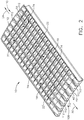
- Cascade 10, as seen in FIG. 1 is a component of a thrust reverser assembly and is mounted to nacelle 12 of a jet engine 14 of aircraft 16.
- a blocker (not shown) of the thrust reverser assembly directs exhaust air flow from jet engine to and through cascade 10.
- the configuration of cascade 10 further directs the exhaust air flow which exits cascade 10.
- Cascades 10 include surfaces which will selectively direct the exhaust air flow in a forward and side directions as needed.
- the direction of the air flow is tailored by the direction of the surfaces of vanes 18, as seen in FIG. 2 , within cascade 10 which selectively direct the exhaust air flow in a forward direction 20 of aircraft 16 and strong-back members 22, which extend in forward and aft directions 20, 24 of aircraft 16 which selectively direct the exhaust air flow in a side-turning direction.
- a method for manufacturing and assembling cascade 10 for a thrust reverser will be discussed herein, wherein the manufacturing and assembly will be streamlined so as to require less labor, cost and production time. Furthermore, the methodology for manufacturing and assembling of cascade 10 in the present disclosure will be performed without compromising the needed aerodynamic performance of cascade 10 which would otherwise lead to yet additional installation and re-certification costs.
- each strip assembly 19 is configured with no more than three sides positioned on one or both sides of strong back member 22 providing a more simplified shape than a four sided shape. This open construction of no more than three sides provides ease in installation, removal and tracking procedures of the strip assemblies 19. Additionally the assembling of strip assemblies 19 into fabricating cascade 10 will permit the fabricator the versatility to provide needed orientation of surfaces with respect to strip assemblies 19 which in turn will not compromise the needed aerodynamic performance of cascade 10.
- method 26 includes step 28 of manufacturing cascade 10 for a thrust reverser for jet engine 14 which includes forming strip assembly 19 by way of methodologies mentioned above an in this example by way of thermal compressing thermoplastic resin.
- Strip assembly 19 includes strong back member 22 having length L, as seen in FIG. 3 .
- Strip assembly 19 further includes plurality of first vane members 30 which extend from a first side 32 of the strong back member 22 in first direction 34 non-parallel relative to length L of strong back member 22 wherein first vane members 30 are spaced apart from one another along length L of strong back member 22.
- Plurality of first vane members 30 includes curvilinear surface 36, as seen in FIG. 5 .
- Curvilinear surface 36 forms recess 38 facing forward direction 20 with respect to aircraft 16, as seen in FIG. 3 , of strip assembly 19.
- Step 28 of manufacturing cascade 10 further includes top portion 42 of curvilinear surface 36 extends in second direction 44 nonparallel relative to central axis 46 of jet engine 14.
- second direction 44 forms angle A relative to central axis 46 of jet engine 14 in a range including thirty degrees up to and including ninety degrees.
- Exhaust air flow of engine 14 is selectively directed in forward direction 20 of aircraft 16 providing braking for aircraft 16 in a landing maneuver.
- Method 26 further includes plurality of second vane members 48, as seen in FIG. 3 .
- Second vane members 48 which extend from second side 50 of the strong back member 22, opposing first side 30 of strong back member 22, in third direction 52 nonparallel relative to length L of strong back member 22.
- the plurality of second vane members 48 are spaced apart from one another along length L of strong back member 22, as seen in FIG. 3 .
- one first vane member 30 of the plurality of first vane members 30 and one second vane member 48 of plurality of second vane members 48 extend in alignment with one another which contribute to providing first embodiment configuration of vane assembly 74 as seen in FIG. 2 and which will be further discussed herein.
- juncture 53 of strong back member 22, first vane member 30 and second vane member 48 is a continuous structure providing a desired strengthened interconnection of strong back member 22 with first and second vane members 30, 48.
- each of plurality of first vane members 30 is positioned to extend from the strong back member 22 in alignment with one second vane member 48 of plurality of the second vane members 48.
- This structure arrangement provides a three sided configuration positioned on either side of strong back member 22 with spaced apart first vane members 30 and first side 32 of strong back 22 on one side of strong back member 22 and second vane members 48 spaced apart on second side 50 of strong back member 22.
- This simplified open configuration for strip assembly 19 provides for less complicated molding steps, less labor efforts along with no compromise in aerodynamic surfaces so as to precipitate a need for recertification.
- first vane member 30 and second vane member 48 are seen in which first vane member 30 extends from strong back member 22 in alignment with one second vane member 48.
- a second example of a configuration of first vane member 30 and second vane member 48 is seen in FIG. 7 wherein a length L' of one of the plurality of first vane member 30 and length L" of one of the plurality of second vane member 48 are positioned in angular relationship to one another.
- This configuration will provide additional support for cascade 10 with respect to exhaust air flow of engine 14 being diverted through cascade 10 as will be discussed further herein with the assembling of cascade 10.
- This configuration will provide the ability to assemble second embodiment of the angular arrangement of vane assembly 74' which will be discussed herein.
- At least one second vane members 48 is similar in construction in this example to first vane members 30, as seen in FIG. 3 .
- At least one second vane member 48 includes curvilinear surface 54 which forms recess 56 and which faces forward direction 20 of aircraft 16.
- Top portion 58 of curvilinear surface 54 of second vane members 48 extends in second direction 44 as shown in FIG. 3 . This configuration is similar to that shown in FIGS. 3 and 5 for first vane members 30.
- Second direction 44 for second vane members 48 is nonparallel to central axis 46 of jet engine 14 (not shown) as is second direction 44 of first vane members 30 such that, with the strip assembly 19 positioned on nacelle 12 of jet engine 14, second direction 44 for second vane members 48 form an angle relative to central axis 46 of jet engine 14 in a range including thirty degrees up to and including ninety degrees, similarly as described above and as shown for first vane member 30 in FIG. 5 .
- Step 28 further includes strong back member 22 including first side surface 32 which extends along length L of strong back member 22 and extends transverse to length L of strong back member 22. Also included is second side surface 50 of strong back member 22 opposing first side 32, wherein second side surface 50 also extends along length L of strong back member 22 and extends transverse to length L of strong back member 22, as seen in FIG. 3 . As seen in FIG. 8 , first side surface 32 of the strong back member 22 has top portion 59 such that, with strip assembly 19 positioned on nacelle 12 of jet engine 14, as seen in FIG.
- top portion 59 of first side surface 32 extends in fourth direction 60 relative to radial direction 62 which extends from central axis 46 of jet engine 14 and aligned with strong back member 22 positioned closer to central axis 46 of jet engine 14 than top portion 59 of first side 32 of strong back member 22.
- Fourth direction 60 extends relative to radial direction 62 within an angular range including extending parallel with radial direction 62 and up to and including being angularly displaced sixty degrees from radial direction 62 as indicated for example by angle B.
- Second side 50 opposing first side 32 of strong back member 22 extends along length L of strong back member 22 and extends transverse to length L of strong back member 22.
- Second side 50 of strong back member 22 has top portion 64 such that, with strip assembly 19 positioned on nacelle 12 of jet engine 14, top portion 64 of second side surface 50 extends in fifth direction 66 relative to radial direction 62 which extends from central axis 46 of jet engine 14 and aligned with strong back member 22 positioned closer to central axis 46 of jet engine 14 than top portion 64 of second side 50 of strong back member 22.
- Fifth direction 66 extends relative to radial direction 62 within an angular range including extending parallel with radial direction 62 and up to and including being angularly displaced sixty degrees from radial direction 62, as seen for example as angle C in FIG. 8 .
- This variable configuration for first surface 32 and second surface 50 of strong back member 22 provides the fabricator the ability to manufacture cascade 10 to provide a selected directed side turning of exhaust air flow from jet engine 14, depending on the position of a particular cascade 10 is located on nacelle 12, so as direct exhaust air flow away from aircraft parts as needed.
- method 68 of assembling cascade 10 for a thrust reverser for jet engine 14 includes step 70 of placing strip assembly 19 into a first position, as seen in FIG. 3 , wherein strip assembly 19 includes strong back member 22 having length L, as earlier described.
- Strip assembly 19 further includes plurality of first vane members 30 which extend from first side 32 of strong back member 22 in first direction 34 nonparallel relative to length L of strong back member 22, as seen in FIG. 3 .
- First vane members 30 are spaced apart from one another along length L of strong back member 22.
- Method 68 further includes step 72 of placing second strip assembly 19' into a second position, as seen in FIG. 3 , wherein second strip assembly 19' includes second strong back member 22' including length L. It is to be noted FIG.
- Second strip assembly 19' further includes plurality of third vane members 48' which extend from second side 50' of second strong back member 22' in a third direction 52, in this example, nonparallel relative to length L of second strong back member 22.
- Plurality of third vane members 48' are spaced apart from one another along length L of second strong back member 22. With strip assembly19 in first position and second strip assembly 19' in second position, one of the plurality of first vane members 30 adjoins one of the plurality of third vane members 48' which form vane assembly 74 as seen for example in FIG. 2 .
- method 68 of assembling further includes distal end 76 of one of the plurality of first vane members 30 relative to first side 32 of the strong back member 22 and distal end 78 of one of plurality of third vane members 48'relative to second side 50' of second strong back member 22' adjoin one another in forming vane assembly 74 as seen in FIG. 3 with utilizing various configurations as will be described herein.
- a first example of the various configurations that can be employed to distal end 76 and distal end 78 includes distal end 76 of first vane member 30 extends along first plane 80, as seen in FIG. 3 and distal end 78 of third vane member 48' extends along second plane 82 wherein first plane 80 and second plane 82 extend in the same direction.
- first vane member 30 and third vane member 48' are adjoined with respect to one another into vane assembly 74.
- a second configuration is shown for example in FIG. 10 .
- Distal end 76 of first vane member 30 of one of plurality of first vane members 30 defines an angularly shaped configuration 84 and distal end 78 of third vane member 48' of one of plurality of third vane members 48' defines a complementary shape 86 relative to angularly shaped configuration 84.
- angularly shaped configuration 84 fits into complementary shape 86 with first vane member 30 and third vane member 48' adjoined with respect to one another into vane assembly 74.
- the configurations for first vane member 30 and for third vane member 48' can be exchanged such that first vane member includes complementary configuration 86 and third vane member 48' includes configuration 84.
- a third configuration is shown for example in FIG. 11 .
- Distal end 76 of first vane member 30 of one of plurality of first vane members 30 defines protrusion 88 and distal end 78 of third vane member 48' of plurality of third vane members 48' defines notch 90.
- Protrusion 88 and notch 90 are complementary in shape to one another interlocking one of plurality of first vane member 30 and one of the plurality of third vane member 48'.
- the configurations for first vane member 30 and for third vane member 48' can be exchanged such that first vane member includes notch 90 and third vane member 48' includes protrusion 88.
- Method 68 of assembling of cascade 10 further includes one of the plurality of first vane members 30, as seen in FIG. 7 extends away from first side 32 of strong back member 22 toward second strong back member 22'.
- One of plurality of third vane members 48' extends away from second side 50' of second strong back member 22' toward strong back member 22 positioning one of the plurality of the first vane members 30 and one of the plurality of third vane members 48'in angular relationship to one another.
- This adjoining configuration provides a strong resistant vane assembly 74 with this angular configuration receiving exhaust air flow moving toward aft direction 24 from jet engine 14 with the thrust reverser in operation.
- Method 68 further includes strong back member 22 including front portion 40 which extends from first side 32 of strong back member 22.
- Second strong back member 22' includes a second front portion 40' which extends from second side 50' of second strong back member 22' as seen for example in FIGS. 3 and 12 . With strip assembly 19 in the first position and second strip assembly 19' in the second position front portion 40 of strong back member 22 adjoins second front portion 40' of second strong back member 22'.
- example configurations are shown of adjoining front portion 40 and second front portion 40'.
- Cascade 10 can utilize one or more of these example configurations of adjoining front portion 40 and second front portion 40' that are shown in FIG. 12 .
- distal end 92 of front portion 40 of strong back member 22 and distal end 94 of second front portion 40' of second strong back member 22' adjoin one another in one of several configurations discussed herein.
- distal end 92 of the front portion 40 of strong back member 22 extends in a first plane 96 (generally represented by arrow 96) and distal end 94 of second front portion 40' of second strong back member 22' extends in second plane 98 (generally represented by arrow 98) wherein first plane 96 and second plane 98 extend in the same direction.
- one of distal end 92 of front portion 40 of strong back member 22 or distal end 94 of second front portion 40' of second strong back member 22' defines an angularly shaped configuration 100. In the example shown in FIG. 12 , distal end 92 has angularly shaped configuration 100.
- distal end 92 of front portion 40 of strong back member 22 or distal end 94 of second front portion 40' of second strong back member 22' defines a complementary shape 102 to the angularly shaped configuration 100.
- distal end 94 has complementary shape 102.
- distal end 92 of front portion 40 of one of front portion 40 of strong back member 22 or distal end 94 of second front portion 40' of second strong member 22' defines protrusion 104.
- distal end 92 of front portion 40 defines protrusion 104.
- the other of distal end 92 of front portion 40 of strong back member 22 or second front portion 40' of second strong back member 22' defines notch 106.
- distal end 94 of second front portion 40' defines notch 106.
- Protrusion 104 and notch 106 are complementary in shape to one another interlocking front portion 40 of strong back member 22 and second front portion 40' of second strong back member 22'.
- Vane assemblies 74 which include for example first vane member 30 and third vane member 48' in cascade 10 and front portions including front portion 40 and second front portion 40' can be secured to secured to one another in the assembling of cascade 10.
- a variety of securements can be used employing methodologies such as patch bonding, glue bonding, welding or applying rivets or other types of fasteners.
- cascade 10 can be assembled onto nacelle 12 with securement of each strip assembly at the opposing ends of the strip assemblies to nacelle 12.
- Cascade 10 as described above includes strip assembly 19, which further includes strong back member 22 having plurality of first vane members 30 which extend from first side 32 of strong back member 22 as seen in FIG. 3 .
- Cascade 10 further includes second strip assembly 19', as seen in FIG. 3 , which also includes second strong back member 22' which further includes plurality of third vane members 48' which extend from second side 50' of second strong back member 22'.
- Strip assembly 19, as seen in FIGS. 2 and 3 is secured in this example at opposing end portions 108, 110 of strip assembly 19 to nacelle 12 with rivets 112 as shown schematically in FIG. 2 .
- Second strip assembly 19' is secured at opposing end portions 108, 110 of second strip assembly 19' to nacelle 12 such that, with each of strip assembly 19 and second strip assembly 19' secured to nacelle 12, distal end 76 of one of the first vane members 30 adjoins distal end 78 of one of third vane members 48'.
- At least one of plurality of first vane members 30 and at least one of plurality of third vane members 48' include curvilinear surface 36 and 54' respectively, as seen in FIGS. 3 and 5 .
- the curvilinear surfaces form recess 38 with respect to first vane members 30 and recess 56' with respect to third vane members 48' which face in forward direction 20 with respect to aircraft 16.
- first vane member 30 which is similar to that of third vane member 48' (not shown), with strip assembly 19 positioned on nacelle 12 of jet engine 14, second direction 44 forms an angle A relative to central axis 46 of jet engine 14 in a range including thirty degrees up to and including ninety degrees.
- This angular range provides the fabricator with the versatility of directing exhaust air flow from first vane member 30 and third vane member 48' into selected needed directions.
- vane assembly 74 which includes length L' of at least one of the plurality of first vane members 30 and length L" of at least one of the plurality of third vane members 48' are positioned in angular relationship to one another forming second vane assembly 74' between strip assembly 19 and second strip assembly 19'.
- Cascade 10 includes strong back member 22, as seen in FIGS. 3 and 8 , which includes first side 32 and second side 50 opposing first side 32.
- First side 32 extends along length L of strong back member 22 and extends transverse to length L of strong back member 22 and second side 50 extends along length L of strong back member 22 and extends transverse to length L of strong back member 22.
- First side 32 of strong back member 22 has top portion 59 such that with strip assembly 19 positioned on nacelle 12 of jet engine 14, top portion 59 of first side 32 extends in fourth direction 60 relative to radial direction 62 which extends from central axis 46 of jet engine 14 and aligned with strong back member 22 positioned closer to central axis 46 of jet engine 14 than top portion 59 of first side 32 of strong back member 22.
- Fourth direction 60 is angularly positioned with respect to radial direction 62 in a directional range which includes parallel to radial direction 62 to and including up to sixty degrees angularly displaced from parallel with radial direction 62.
- second side 50 of strong back member 22 has top portion 64 such that with strip assembly 19 positioned on nacelle 12 of jet engine 14 top portion 64 of second side 50 extends in fifth direction 66 relative to radial direction 62 which extends from central axis 46 of jet engine 14 and aligned with strong back member 22 positioned closer to central axis 46 of jet engine 14 than top portion 59 of second side 50 of strong back member 22.
- Fifth direction 66 is angularly positioned with respect to radial direction 62 in a directional range which includes parallel to radial direction 62 to and including up to sixty degrees angularly displaced from parallel with radial direction 62.
- Cascade 10 further includes at least one of the plurality of the first vane members 30 include a distal end 76 relative to strong back member 22.
- Cascade 10 further includes at least one of the plurality of third vane members 48' which includes distal end 78 relative to second strong back member 22.
- Distal end 76 of first vane members 30 adjoin distal end 78 of third vane members 48'in one of the several configurations described herein.
- distal end 76 of at least one of the first vane members 30 extends along in first plane 96 and distal end 78 of one of the third vane members 48'extends along in second plane 98, wherein first plane 96 and second plane 98 extend in the same direction.
- distal end 76 of one of the plurality of first vane members 30 or distal end 78 of one of the plurality of third vane members 48' defines an angularly shaped configuration 84 and distal end 78 of the other of one of the plurality of first vane members 30 or of one of the plurality of third vane members 48' defines complementary shape 86 relative to angularly shaped configuration 84.
- distal end 76 defines angularly shaped configuration 84 and distal end 78 defines complementary shape 86.
- a third configuration example as seen in FIG.
- distal end 76 of one of the plurality of first vane members 30 or distal end 78 of one of the plurality of third vane members 48' defines protrusion 88.
- Distal end 76 of the other of one of the plurality of first vane members 30 or of the one of the plurality of the third vane members 48' defines notch 90.
- Protrusion 88 and notch 90 are complementary in shape to one another interlocking one of the plurality of the first vane members 30 and one of the plurality of the third vane members 48'.
- another method 112 for manufacturing another example of cascade 10', for a thrust reverser for a jet engine 14 includes the step of forming 114 vane strip assembly 116 which includes vane member 118 which comprises length 120 and a plurality of first strong back members 122 which extend from first side 124 of vane member 118 in first direction 123.
- First direction 123 is nonparallel relative to length 120 of vane member 118 wherein plurality of the first strong back members 122 are spaced apart from one another along length L of vane member 118.
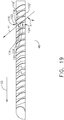
- the step of forming 114 further includes vane member 118, as seen in FIG. 3 , including curvilinear surface 128 wherein curvilinear surface 128 forms recess 130 facing forward direction 20. This configuration is also seen in FIG. 19 . Further included is top portion 126 of curvilinear surface 128 which extends in a second direction 44 nonparallel relative to central axis 46 of jet engine 14 such that, with vane strip assembly 116 positioned on nacelle 12 of jet engine 14, second direction 44 forms an angle A relative to central axis 46 of jet engine 14 in a range including thirty degrees up to and including ninety degrees providing turning jet engine 14 thrust into a direction more aligned in this example with forward direction 20.
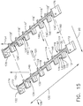
- Step 114 of forming further includes a plurality of second strong back members 132, as seen in FIG. 15 , which extend from second side 134 of vane member 118, opposing first side 124 of vane member 118, in third direction 136 nonparallel relative to length 120 of vane member 118.
- Plurality of second strong back members 132 are spaced apart from one another along length L of vane member 118.
- Step 114 of forming further includes one first strong back member 122 of the plurality of first strong back members 122 and one second strong back member 132 of the plurality of second strong back members 132 extend in alignment with one another.
- each of plurality of the first strong back members 122 is positioned to extend from vane member 118 in alignment with one second strong back member 132 of the plurality of the second strong back members 132.
- Step 114 of forming of method 112 further includes first strong back member 122 of FIG. 15 can be seen as earlier described and similarly structured strong back member 22 in FIG. 8 .
- the configuration of first strong back member 122 will be described in relationship to FIG. 8 wherein first strong back member 122 will be referred to and shown as strong back member 22, in FIG. 8 .
- Strong back 22 includes first side 32 and second side 50 opposing first side 32.
- First side 50 of the strong back member 22 has a top portion 59 such that, with the vane strip assembly 116 positioned in cascade 10', as seen in FIG. 14 and secured, for example, to nacelle 12 as shown for cascade 10 in FIG. 1 , top portion 59 of first side 32 extends in fourth direction 60 relative to radial direction 62.
- Radial direction 62 extends from central axis 46 of jet engine 14, as seen in FIG. 8 and is aligned with strong back member 22 positioned closer to central axis 46 of jet engine 14 than top portion 59 of first side 32 of strong back member 22.
- Fourth direction 60 represents a direction in which first side 32 extends for this example.
- Fourth direction 60 extends in a direction relative to radial direction 62 within an angular range including extending parallel with radial direction 62 and up to and including being angularly displaced sixty degrees from radial direction 62.
- strong back member 22 can be angularly positioned as chosen and also shown in FIG. 8 .
- Strong back member 22 has second side 50 that has top portion 64 such that, with vane strip assembly 116 as part of cascade 10', as seen in FIG. 14 , and vane strip assembly 116 further positioned on nacelle 12 of jet engine 14, as for example shown for cascade 10 in FIG.
- top portion 64 of second side 50 extends in fifth direction 66 relative to radial direction 62, in another example, which extends from central axis 46 of jet engine 14 and aligned with strong back member 22 positioned closer to central axis 46 of jet engine 14 than top portion 64 of second side 50 of strong back member 22.
- Fifth direction 66 extends relative to radial direction 62 within an angular range including extending parallel with radial direction 62 and up to and including being angularly displaced sixty degrees from radial direction 62.
- method 138 for assembling cascade 10' for a thrust reverser for a jet engine 14 includes step 140 for placing vane strip assembly 116 into a first position, as seen in FIG. 15 .
- Vane strip assembly 116 includes vane member 118 which includes length 120.
- Vane strip assembly 116 further includes plurality of first strong back members 122 which extend from first side 124 of vane member 118 in first direction 123 nonparallel relative to length 120 of vane member118.
- First strong back members 122 are spaced apart from one another along length 120 of vane member 118 as seen in FIG. 15 .
- Method 138 of FIG. 16 further includes step 142 for placing second vane strip assembly 116' into a second position, as seen in FIG. 15 , wherein second vane strip assembly 116' includes second vane member 118' which includes length 120.
- Second vane strip assembly 116' further includes plurality of third strong back members 132' which extend from second side 134' of second vane member 118' in third direction 146 nonparallel relative to length 120 of second vane member 118'.
- Plurality of third strong back members 132' are spaced apart from one another along length 120 of second vane member 118'.
- Method 138 of assembling includes a distal end 148 of one of the plurality of first strong back members 122, relative to first side 124 of vane member 118, and distal end 150 of the one of the plurality of third strong back members 132', relative to second side 134' of the second vane member 118', adjoin one another in one of the following discussed configurations.
- distal end 148 of one of the first strong back members 122 as seen in FIG.
- first plane 152 and second plane 154 extend in the same direction which includes one of a wide selection of directions.
- distal end 156 of one of plurality of strong back members 122 or distal end 158 of one of the plurality of third strong back members 132' defines an angularly shaped configuration 160.
- the angular configuration 160 is associated with distal end 156 of strong back member 122.
- Distal end of the other of the one of the plurality of first strong back members 122 or of the one of the plurality of third strong back members 132' defines a complementary shape 162 relative to the angularly shaped configuration 160.
- the complementary shape 162 is associated with distal end 158 of third strong back member 132'. This alignment of distal ends can be reversed such that angularly shaped configuration 160 could be associated with distal end 158 and the complementary shape 162 could be associated with distal end 156.
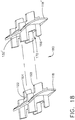
- distal end of one of the plurality of first strong back members 122 or a distal end of the one of the plurality of third strong back members 132' defines a protrusion 168 and the distal end of the other of the one of the plurality of first strong back members 122 or of the one of the plurality of the third strong back members 132' defines notch 170, wherein protrusion 168 and notch 170 are complementary in shape to one another permitting interlocking of one of the plurality of the first strong back member 122 and the one of the plurality of the third strong back member 132'.
- FIG. 18 distal end of one of the plurality of first strong back members 122 or a distal end of the one of the plurality of third strong back members 132' defines a protrusion 168 and the distal end of the other of the one of the plurality of first strong back members 122 or of the one of the plurality of the third strong back members 132' defines notch 170, wherein protrusion 168 and notch 170 are complementary in
- the protrusion 168 is associated with distal end 164 of first strong back member 122 and notch 170 is associated with distal end 166 of third strong back member 132'.
- the alignment of distal ends can be reversed such that protrusion 168 can be associated with distal end 166 and notch 170 can be associated with distal end 164.
- reverse thruster cascade 10' includes vane strip assembly 116 which includes vane member 118 including plurality of first strong back members 122 which extend from first side 124 of vane member 118.
- Second vane strip assembly 116' includes second vane member 118' including a plurality of third strong back members 132' which extend from second side 134' of second vane member 118'.
- Vane strip assembly 116 is secured at opposing end portions 172, 174 of vane strip assembly 116 to nacelle 12, as seen for cascade 10 in FIG. 1 .
- Second vane strip assembly 116' is secured at opposing end portions 176, 178 of second vane strip assembly 116' to nacelle 12, as also seen for cascade 10 in FIG. 1 .
- a distal end 148, for example as seen in FIG. 15 of one of the plurality of first strong back members 122 adjoins distal end 150 of one of the plurality of third strong back members 132'.
- vane member 118 and second vane member 118' include a curvilinear surface 128 wherein curvilinear surface 128 forms recess 130 facing forward position 20. This is seen in FIG. 15 and shown as well in FIG. 19 .
- Vane member 118 a top portion 126 of curvilinear surface 128 extends in second direction 44 nonparallel relative to central axis 46 of jet engine 14 such that, with vane strip assembly 116 positioned on nacelle 12 of jet engine 14, such as seen for example in FIG. 1 .
- Second direction 44 forms an angle A relative to central axis 46 of jet engine 14 in a range including thirty degrees up to and including ninety degrees.
- adjoining first strong back member 122 and third strong back member 132' forming a strong back assembly 180 will often have similar curvature configurations with respect to one another such as to direct engine exhaust from strong back assembly 180 in a desired direction laterally with respect to engine 14.
- First strong back member 122 includes, as earlier discussed as being similar in structure as strong back member 22 and shown in FIG. 8 , a first side 32 and second side 50 opposing first side 32.
- First side 32 of first strong back member 122 has top portion 59 such that with vane strip assembly 116 positioned on nacelle 12 of jet engine 14, top portion 59 of first side 32 extends in fourth direction 60 relative to radial direction 62.
- Radial direction 62 extends from central axis 46 of jet engine 14 aligned with first strong back member 122 positioned closer to central axis 46 of jet engine 14 than top portion 59 of first side 32 of first strong back member 122.
- Fourth direction 60 in this example, is angularly positioned with respect to radial direction 62 in an angular range which includes parallel to radial direction 62 to and including up to sixty degrees angularly displaced from parallel with radial direction 62.
- Second side 50 as seen in FIG. 8 , strong back member 22, which is similarly structured to first strong back members 122, has top portion 64 such that with vane strip assembly 116 positioned on nacelle 12 of jet engine 14, as seen for example with respect to cascade 10 in FIG. 1 , top portion 64 of second side 50 extends in fifth direction 66 relative to radial direction 62.
- Radial direction 62 extends from central axis 46 of jet engine 14 aligned with strong back member 22, as seen in FIG. 8 , positioned closer to central axis 46 of jet engine 14 than top portion 64 of second side 50 of strong back member 22 and similarly for first strong back member 122.
- Fifth direction 66 in this example, is angularly positioned with respect to radial direction 62 in an angular range which includes parallel to radial direction 62 to and including up to sixty degrees angularly displaced from parallel with radial direction 62.
- distal end 148 of one of plurality of the first strong back members 122 and distal end 150 of one of the plurality of third strong back members 132' adjoin one another in one of the following configurations discussed herein.
- distal end 148 of one of the plurality of first strong back members 122 extend along in first plane 152
- distal end 150 of the one of the plurality of third strong back members 132' extend along in a second plane 154 wherein first plane 152 and second plane 154 extend in the same direction.
- distal end 156 of one of plurality of strong back members 122 or distal end 158 of one of the plurality of third strong back members 132' defines an angularly shaped configuration 160.
- the angular configuration 160 is associated with distal end 156 of strong back member 122.
- Distal end of the other of the one of the plurality of first strong back members 122 or of the one of the plurality of third strong back members 132' defines a complementary shape 162 relative to the angularly shaped configuration 160.
- the complementary shape 162 is associated with distal end 158 of third strong back member 132'. This alignment of distal ends can be reversed such that angularly shaped configuration 160 could be associated with distal end 158 and the complementary shape 162 could be associated with distal end 156.
- distal end of one of the plurality of first strong back members 122 or a distal end of the one of the plurality of third strong back members 132' defines a protrusion 168 and the distal end of the other of the one of the plurality of first strong back members 122 or of the one of the plurality of the third strong back members 132' defines notch 170, wherein protrusion 168 and notch 170 are complementary in shape to one another permitting interlocking of one of the plurality of the first strong back member 122 and the one of the plurality of the third strong back member 132'.
- FIG. 18 distal end of one of the plurality of first strong back members 122 or a distal end of the one of the plurality of third strong back members 132' defines a protrusion 168 and the distal end of the other of the one of the plurality of first strong back members 122 or of the one of the plurality of the third strong back members 132' defines notch 170, wherein protrusion 168 and notch 170 are complementary in
- the protrusion 168 is associated with distal end 164 of first strong back member 122 and notch 170 is associated with distal end 166 of third strong back member 132'.
- the alignment of distal ends can be reversed such that protrusion 168 can be associated with distal end 166 and notch 170 can be associated with distal end 164.
- Reverse thruster cascade 10' as shown in FIGS. 14 and 15 includes vane strip assembly 116 which includes vane member 118 including a plurality of first strong back members 122 which extend from first side 124 of vane member 118.
- Cascade 10' further includes second vane strip assembly 116' including second vane member 118'including a plurality of third strong back members 132'which extend from second side 134' of second vane member 118.
- Vane strip assembly 116 is secured at opposing end portions 172, 174 of vane strip assembly 116 to nacelle 12 with a securement commonly used for securement to nacelle 12.
- Second vane strip assembly 116' is secured at opposing end portions 176, 178 of second vane strip assembly 116' to nacelle 12, also with a securement commonly used for securement to nacelle 12, such that with each of vane strip assembly 116 and second vane strip assembly 116'secured to nacelle 12 a distal end 148 of one of plurality of first strong back members 122 adjoins distal end 150 of one of the plurality of third strong back members 132'.
Landscapes
- Engineering & Computer Science (AREA)
- Chemical & Material Sciences (AREA)
- Combustion & Propulsion (AREA)
- Mechanical Engineering (AREA)
- General Engineering & Computer Science (AREA)
- Turbine Rotor Nozzle Sealing (AREA)
- Wind Motors (AREA)
Abstract
Description
- This disclosure relates to a cascade for a thrust reverser for a jet engine and more particularly to a method of manufacturing and assembling of the cascade.
- Thrust reversers are devices used to turn jet engine exhaust to a direction with a sufficient forward component to create reverse thrust to enable aerodynamic breaking during an airplane landing maneuver. A cascade is a component of the thrust reverser assembly mounted to a nacelle of a jet engine. A blocker door of the thrust reverser assembly directs exhaust air flow to and through the cascade and the cascade configuration further directs the exhaust air flow which exits the cascade.
- A cascade typically includes surfaces which will selectively direct the exhaust flow in forward and side directions. The direction of the exhaust air flow is tailored by the direction of the surfaces of vanes and strong backs within the cascade. Vane surfaces selectively direct the exhaust air flow in a forward direction and strong backs selectively direct the exhaust air flow in a side-turning direction. Cascades, as a result of having surfaces which direct exhaust air flow in varied directions, have a complex shape. The complex shape results in considerable labor, cost and turnaround time for production.
- Cascades have been made conventionally with composite material by way of hand layups. This fabrication methodology is labor intensive and results in a high cost. Other methods of manufacturing cascades has included compression mold thermoplastic manufacturing processes which is less labor intensive but which has complex four sided mold designs which result in requiring complicated mold shapes. With the cascade having four sided structures, this configuration has necessitated complicated installation, removal and tracking procedures of these molded pieces which add cost penalties with respect to labor efforts required and the length of time of the process.
- Although the above compression mold thermoplastic manufacturing process can be streamlined to reduce manufacturing cost, the streamlining requires simplification of the aerodynamic lines of the cascade geometry which directs the exhaust air flow. As a result of simplification of the aerodynamic lines of the cascade geometry, the reverse thruster aerodynamic performance is penalized. To compensate for the reduced aerodynamic performance relatively larger cascades are required. These cascades are typically required to be longer. This increase in size further contributes to increased weight and installation challenges such as, the aerolines of the fan outer wall and external nacelle, longer actuators etc. Any change in aerolines requires re-certification costs and further additional testing costs.
- There is a need to manufacture cascades which perform the needed function of directing exhaust air flow from the jet engine. The cascade will need to direct the exhaust air flow in various directions so as to avoid imparting wear onto different parts of the aircraft and to direct flow in a forward direction of the aircraft to slow down the speed of the aircraft after the aircraft has touched down on the airstrip in a landing maneuver. The manufacturing of cascades also needs to be less labor intensive and less expensive without compromising the needed aerodynamic performance of the cascade which would otherwise place increased challenges on installation and impose cost penalties associated with re-certification.
- An example of a method for manufacturing a cascade for a thrust reverser for a jet engine includes forming a strip assembly. The strip assembly includes a strong back member which includes a length. The strip assembly also includes a plurality of first vane members which extend from a first side of the strong back member in a first direction nonparallel relative to the length of strong back member wherein the plurality of the first vane members are spaced apart from one another along the length of the strong back member.
- An example of a method of assembling a cascade for a thrust reverser for a jet engine includes the steps of placing a strip assembly into a first position wherein the strip assembly includes a strong back member having a length. The strip assembly further includes a plurality of first vane members which extend from a first side of the strong back member in a first direction nonparallel relative to the length of strong back member wherein the first vane members are spaced apart from one another along the length of the strong back member. The method further includes placing a second strip assembly into a second position wherein the second strip assembly includes a second strong back member which includes a length. The second strip assembly further includes a plurality of third vane members which extend from a second side of the second strong back member in a third direction nonparallel relative to the length of the second strong back member wherein the plurality of third vane members are spaced apart from one another along the length of the second strong back member. With the strip assembly in the first position and the second strip assembly in the second position, one of the plurality of first vane members adjoins one of the plurality of third vane members.
- An example of a thrust reverser cascade includes a strip assembly which includes a strong back member which further includes a plurality of first vane members which extend from a first side of the strong back member. Also included is a second strip assembly which includes a second strong back member which includes a plurality of third vane members which extend from a second side of the second strong back member. The strip assembly is secured at opposing end portions of the strip assembly to a nacelle and the second strip assembly is secured at opposing end portions of the second strip assembly to the nacelle. With each of the strip assembly and the second strip assembly secured to the nacelle, a distal end of one of the first vane members adjoins a distal end of one of the third vane members.
- An example of a method for manufacturing a cascade for a thrust reverser for a jet engine which includes forming a vane strip assembly, wherein the vane strip assembly includes a vane member comprising a length; and a plurality of first strong back members which extend from a first side of the vane member in a first direction nonparallel relative to the length of the vane member wherein the plurality of the first strong back members are spaced apart from one another along the length of the vane member.
- An example of a method for assembling a cascade for a thrust reverser for a jet engine which includes the steps of placing a vane strip assembly into a first position wherein the vane strip assembly includes: a vane member comprising a length; and a plurality of first strong back members which extend from a first side of the vane member in a first direction nonparallel relative to the length of the vane member wherein the first strong back members are spaced apart from one another along the length of the vane member. The method further includes the step of placing a second vane strip assembly into a second position wherein the second vane strip assembly which includes: a second vane member comprising a length; and a plurality of third strong back members which extend from a second side of the second vane member in a third direction nonparallel relative to the length of the second vane member. The plurality of third strong back members are spaced apart from one another along the length of the second vane member; and with the strip assembly in the first position and the second vane strip assembly in the second position, one of the plurality of first strong back members adjoins one of the plurality of third strong back members.
- An example includes a reverse thruster cascade which includes a vane strip assembly which includes a vane member comprising a plurality of first strong back members which extend from a first side of the vane member. The reverse thruster cascade further includes a second vane strip assembly including a second vane member comprising a plurality of third strong back members which extend from a second side of the second vane member. The vane strip assembly is secured at opposing end portions of the vane strip assembly to a nacelle. The second vane strip assembly is secured at opposing end portions of the second vane strip assembly to the nacelle such that with each of the vane strip assembly and the second vane assembly secured to the nacelle a distal end of one of the plurality of the first strong back members adjoins a distal end of one of the plurality of the third strong back members.
- The features, functions, and advantages that have been discussed can be achieved independently in various embodiments or may be combined in yet other embodiments further details of which can be seen with reference to the following description and drawings.
- Clause 1. A method of assembling a cascade for a thrust reverser for a jet engine, comprising the steps of: placing a strip assembly into a first position wherein the strip assembly comprises: a strong back member comprising a length; and a plurality of first vane members which extend from a first side of the strong back member in a first direction nonparallel relative to the length of the strong back member wherein the first vane members are spaced apart from one another along the length of the strong back member; and placing a second strip assembly into a second position wherein the second strip assembly comprises: a second strong back member comprising a length; and a plurality of third vane members which extend from a second side of the second strong back member in a third direction nonparallel relative to the length of the second strong back member wherein: the plurality of third vane members are spaced apart from one another along the length of the second strong back member; and with the strip assembly in the first position and the second strip assembly in the second position, one of the plurality of first vane members adjoins one of the plurality of third vane members.
- Clause 2. The method of assembling of clause 1, further includes a distal end of the one of the plurality of first vane members relative to the first side of the strong back member and a distal end of the one of the plurality of third vane members relative to the second side of the second strong back member, adjoin one another in one of the following configurations:
- the distal end of the one of the first vane members extend along in a first plane and the distal end of the one of the third vane members extend along in a second plane wherein the first plane and the second plane extend in the same direction; or
- the distal end of the one of the plurality of first vane members or a distal end of the one of the plurality of third vane members defines an angularly shaped configuration and the distal end of the other of the one of the plurality of first vane members or of the one of the plurality of third vane members defines a complementary shape relative to the angularly shaped configuration; or
- the distal end of the one of the plurality of first vane members or a distal end of the one of the plurality of third vane members defines a protrusion and the distal end of the other of the one of the plurality of first vane members or of the one of the plurality of the third vane members defines a notch wherein the protrusion and the notch are complementary in shape to one another interlocking the one of the plurality of the first vane member and the one of the plurality of the third vane member.
- Clause 3. The method of assembling of clause 1 or -2, further includes the one of the plurality of first vane members extends away from the first side of the strong back member toward the second strong back member and the one of the plurality of third vane members extends away from the second side of the second strong back member toward the strong back member positioning the one of the plurality of the first vane members and the one of the plurality of third vane members in angular relationship to one another.
- Clause 4. The method of assembling of any of clauses 1 to 3, wherein:
- the strong back member includes a front portion which extends from the first side of the strong back member; and
- the second strong back member includes a second front portion which extends from the second side of the second strong back member and with the strip assembly in the first position and the second strip assembly in the second position the front portion of the strong back member adjoins the second front portion of the second strong back member, wherein a distal end of the front portion of the strong back member and a distal end of the second front portion of the second strong back member adjoin one another in one of the following configurations:
- the distal end of the front portion of the strong back member extends in a first plane and the distal end of the second front portion of the second strong back member extends in a second plane wherein the first plane and the second plane extend in the same direction; or
- one of the distal end of the front portion of the strong back member or the distal end of the second front portion of the second strong back member defines an angularly shaped configuration and the other of the distal end of the front portion of the strong back member or
- the distal end of the second front portion of the second strong back member defines a complementary shape to the angularly shaped configuration; or
- the distal end of the front portion of one of the front portion of the strong back member or the distal end of the second front portion of the second strong member defines a protrusion and the other of the distal end of the front portion of the strong back member or the second front portion of the second strong back member defines a notch wherein the protrusion and the notch are complementary in shape to one another interlocking the front portion of the strong back member and the second front portion of the second strong back member.
- Clause 5. A method for manufacturing a cascade for a thrust reverser for a jet engine, comprising:
- forming a vane strip assembly, wherein the vane strip assembly comprises:
- a vane member comprising a length; and
- a plurality of first strong back members which extend from a first side of the vane member in a first direction nonparallel relative to the length of the vane member wherein the plurality of the first strong back members are spaced apart from one another along the length of the vane member.
- Clause 6. The method of clause 5, wherein the step of forming further includes the vane member comprises a curvilinear surface wherein the curvilinear surface forms a recess facing a forward direction.
- Clause 7. The method of clause 6, wherein the step of forming further includes a top portion of the curvilinear surface extends in a second direction nonparallel relative to a central axis of the jet engine such that, with the vane strip assembly positioned on a nacelle of the jet engine, the second direction forms an angle relative to the central axis of the jet engine in a range including thirty degrees up to and including ninety degrees.
-
Clause 8. The method of any of clauses 5 to 7, wherein the step forming further includes a plurality of second strong back members which extend from a second side of the vane member, opposing the first side of the vane member, in a third direction nonparallel relative to the length of the vane member wherein the plurality of second strong back members are spaced apart from one another along the length of the vane member. - Clause 9. The method of
clause 8, wherein the step of forming further includes one first strong back member of the plurality of first strong back members and one second strong back member of the plurality of second strong back members extend in alignment with one another. -
Clause 10. The method of clause 9, wherein the step of forming further includes each of the plurality of the first strong back members is positioned to extend from the vane member in alignment with one second strong back member of the plurality of the second strong back members. - Clause 11. The method of any of clauses 5 to 10, wherein the step of forming further includes the first strong back member comprising a first side and a second side opposing the first side, wherein:
- the first side of the first strong back member has a top portion such that, with the vane strip assembly positioned on the nacelle of the jet engine, the top portion of the first side extends in a fourth direction relative to a radial direction, which extends from the central axis of the jet engine and aligned with the strong back member positioned closer to the central axis of the jet engine than the top portion of the first side of the first strong back member, wherein
- the fourth direction extends relative to the radial direction within an angular range including extending parallel with the radial direction and up to and including being angularly displaced sixty degrees from the radial direction; and
- the second side of the first strong back member has a top portion such that, with the vane strip assembly positioned on the nacelle of the jet engine, the top portion of the second side extends in a fifth direction relative to the radial direction, which extends from the central axis of the jet engine and aligned with the strong back member positioned closer to the central axis of the jet engine than the top portion of the second side of the first strong back member, wherein the fifth direction extends relative to the radial direction within an angular range including extending parallel with the radial direction and up to and including being angularly displaced sixty degrees from the radial direction.
-
Clause 12. A method for assembling a cascade for a thrust reverser for a jet engine, comprising the steps of: - placing a vane strip assembly into a first position wherein the vane strip assembly comprises:
- a vane member comprising a length; and
- a plurality of first strong back members which extend from a first side of the vane member in a first direction nonparallel relative to the length of the vane member wherein the first strong back members are spaced apart from one another along the length of the vane member; and
- placing a second vane strip assembly into a second position wherein the second vane strip assembly comprises:
- a second vane member comprising a length; and
- a plurality of third strong back members which extend from a second side of the second vane member in a third direction nonparallel relative to the length of the second vane member, wherein:
- the plurality of third strong back members are spaced apart from one another along the length of the second vane member; and
- with the strip assembly in the first position and the second vane strip assembly in the second position, one of the plurality of first strong back members adjoins one of the plurality of third strong back members.
- Clause 13. The method of assembling of
clause 12, further includes a distal end of the one of the plurality of first strong back members relative to the first side of the vane member and a distal end of the one of the plurality of third strong back members relative to the second side of the second vane member, adjoin one another in one of the following configurations: - the distal end of the one of the first strong back members extend along in a first plane and the distal end of the one of the third strong back members extend along in a second plane wherein the first plane and the second plane extend in the same direction; or
- the distal end of the one of the plurality of strong back members or a distal end of the one of the plurality of third strong back members defines an angularly shaped configuration and the distal end of the other of the one of the plurality of first strong back members or of the one of the plurality of third strong back members defines a complementary shape relative to the angularly shaped configuration; or
- the distal end of the one of the plurality of first strong back members or a distal end of the one of the plurality of third strong back members defines a protrusion and the distal end of the other of the one of the plurality of first strong back members or of the one of the plurality of the third strong back members defines a notch wherein the protrusion and the notch are complementary in shape to one another interlocking the one of the plurality of the first strong back member and the one of the plurality of the third strong back member.
-
Clause 14. A reverse thruster cascade, comprising: - a vane strip assembly comprising a vane member comprising a plurality of first strong back members which extend from a first side of the vane member;
- a second vane strip assembly comprising a second vane member comprising a plurality of third strong back members which extend from a second side of the second vane member; wherein:
- the vane strip assembly is secured at opposing end portions of the vane strip assembly to a nacelle; and
- the second vane strip assembly is secured at opposing end portions of the second vane strip assembly to the nacelle such that with each of the vane strip assembly and the second vane assembly secured to the nacelle a distal end of one of the plurality of the first strong back members adjoins a distal end of one of the plurality of the third strong back members.
- Clause 15. The reverse thruster cascade of
clause 14, wherein: - at least one of the vane member and the second vane member comprise a curvilinear surface;
- the curvilinear surface forms a recess facing a forward position; and
- a top portion of the curvilinear surface extends in a second direction nonparallel relative to a central axis of the jet engine such that, with the vane strip assembly positioned on a nacelle of the jet engine, the second direction forms an angle relative to the central axis of the jet engine in a range including thirty degrees up to and including ninety degrees.
-
Clause 16. The reverse thruster cascade ofclause 14 or 15, wherein the one of the plurality of first strong back members and the one of the plurality of third vane members extend in alignment with one another forming a strong back assembly between the vane strip assembly and the second vane strip assembly. - Clause 17. The reverse thruster cascade of any of
clauses 14 to 16 wherein: - first strong back member comprises a first side and a second side opposing the first side;
- the first side of the first strong back member has a top portion such that with the vane strip assembly positioned on the nacelle of the jet engine, the top portion of the first side extends in a fourth direction relative to a radial direction, which extends from the central axis of the jet engine and aligned with the first strong back member positioned closer to the central axis of the jet engine than the top portion of the first side of the first strong back member;
- the fourth direction is angularly positioned with respect to the radial direction in an angular range which includes parallel to the radial direction to and including up to sixty degrees angularly displaced from parallel with the radial direction;
- the second side of the first strong back member has a top portion such that with the vane strip assembly positioned on the nacelle of the jet engine the top portion of the second side extends in a fifth direction relative to the radial direction which extends from the central axis of the jet engine and aligned with the strong back member positioned closer to the central axis of the jet engine than the top portion of the second side of the first strong back member; and the fifth direction is angularly positioned with respect to the radial direction in an angular range which includes parallel to the radial direction to and including up to sixty degrees angularly displaced from parallel with the radial direction.
-
Clause 18. The reverse thruster cascade of any ofclauses 14 to 17, further comprising: - the distal end of one of the plurality of the first strong back members and the distal end of one of the plurality of the third strong back members adjoin one another in one of the following configurations:
- the distal end of the one of the plurality of the first strong back members extend along in a first plane and the distal end of the one of the plurality of the third strong back members extend along in a second plane wherein the first plane and the second plane extend in the same direction; or
- the distal end of the one of the plurality of first strong back members or a distal end of the one of the plurality of third vane members defines an angularly shaped configuration and the distal end of the other of the one of the plurality of first vane members or of the one of the plurality of third vane members defines a complementary shape relative to the angularly shaped configuration; or
- the distal end of the one of the plurality of first strong back members or a distal end of the one of the plurality of third strong back members defines a protrusion and the distal end of the other of the one of the plurality of first strong back members or of the one of the plurality of the third strong back members defines a notch wherein the protrusion and the notch are complementary in shape to one another interlocking the one of the plurality of the first strong back members and the one of the plurality of the third strong back members.
-
Clause 19. A reverse thruster cascade, comprising: - a vane strip assembly which comprises a vane member comprising a plurality of first strong back members which extend from a first side of the vane member; and
- a second vane strip assembly comprising a second vane member comprising a plurality of third strong back members which extend from a second side of the second vane member, wherein:
- a vane strip assembly is secured at opposing end portions of the vane strip assembly to a nacelle; and
- the second vane strip assembly is secured at opposing end portions of the second vane strip assembly to the nacelle such that with each of the vane strip assembly and the second vane strip assembly secured to the nacelle, a distal end of one of the plurality of the first strong back members adjoins a distal end of one of the plurality of the third strong back members.
-
-
FIG. 1 is a partial perspective view of an aircraft with a jet engine mounted to a wing and with cascades positioned on a nacelle of the jet engine with the thrust reverser of the jet engine in operation; -
FIG. 2 is a perspective view of an assembled cascade fromFIG. 1 showing a first example of a configuration of adjoining distal end portions of vanes of a vane assembly positioned between adjoining strong backs and a first embodiment of a configuration of the vane assembly extending between adjoining strong backs; -
FIG. 3 is a perspective blown apart view of two adjoining cascade strip assemblies from an unassembled cascade ofFIG. 2 ; -
FIG. 4 flow chart of a method for manufacturing a cascade for a thrust reverser for a jet engine; -
FIG. 5 is an enlarged partial side elevation view of a cascade strip assembly ofFIG. 3 showing a central axis of the jet engine to which the cascade is associated; -
FIG. 6 . is a partial top perspective enlarged view of the juncture between a strong back member and first vane members and second vane members, ofFIG. 3 , wherein an example of a configuration of the first vane member and the second vane member extend from the strong back member in alignment with one another is shown; -
FIG. 7 is a partial enlarged top elevation view of a second embodiment of a configuration of the first vane member and the second vane member extend from the strong back member positioned in angular relationship to one another; -
FIG. 8 is a cross section view along line 8-8 of a strong back of a strip assembly of a cascade as seen inFIG. 3 showing examples of angular variations of strong back configurations relative to a radial direction extending from a central axis of the jet engine; -
FIG. 9 is a flow chart of a method for assembling a cascade for a thrust reverser for a jet engine; -
FIG. 10 is a partial perspective blown apart view of two adjoining strip assemblies of an assembled cascade showing a second example of a configuration of adjoining distal end portions of vanes of the vane assembly positioned between adjoining strong backs; -
FIG. 11 is a partial perspective blown apart view of two adjoining strip assemblies from an assembled cascade showing a third example of a configuration of adjoining distal end portions of vanes of the vane assembly positioned between adjoining strong backs;FIG. 12 is a forward end elevation view of the cascade ofFIG. 2 showing first, second and third examples of different forward end configurations of adjoining front portions of the cascade; -
FIG. 13 is a flow chart of another method for manufacturing a thrust reverser for a jet engine; -
FIG. 14 is a perspective view of an assembled cascade fromFIG. 1 showing a first example of a configuration of adjoining distal end portions of strong back members of adjoining vane strip assemblies; -
FIG. 15 is a perspective blown apart view of two adjoining vane strip assemblies from an unassembled cascade ofFIG. 13 ; -
FIG. 16 is a flow chart of another method for manufacturing a cascade for a thrust reverser for a jet engine ofFIG. 13 ; -
FIG. 17 is a partial perspective blown apart view of two adjoining vane strip assemblies of an assembled cascade ofFIG. 13 showing a second example of a configuration of adjoining distal end portions of strong back members of a strong back assembly positioned between adjoining vane strip assemblies; -
FIG. 18 is a partial perspective blown apart view of two adjoining vane strip assemblies from an assembled cascade showing a third example of a configuration of adjoining distal end portions of strong back members of a strong back assembly positioned between adjoining vane strip assemblies; and -
FIG. 19 is a cross section taken along line 19-19 inFIG. 13 showing first, second and third examples of different adjoining configurations of strong back members of adjoining vane strip assemblies. - As discussed above, thrust reversers are devices used to turn jet engine exhaust to a direction with a sufficient forward component to create reverse thrust to enable aerodynamic breaking during an airplane landing maneuver.
Cascade 10, as seen inFIG. 1 , is a component of a thrust reverser assembly and is mounted to nacelle 12 of ajet engine 14 ofaircraft 16. A blocker (not shown) of the thrust reverser assembly directs exhaust air flow from jet engine to and throughcascade 10. The configuration ofcascade 10 further directs the exhaust air flow which exitscascade 10. -
Cascades 10, as previously mentioned, include surfaces which will selectively direct the exhaust air flow in a forward and side directions as needed. The direction of the air flow is tailored by the direction of the surfaces ofvanes 18, as seen inFIG. 2 , withincascade 10 which selectively direct the exhaust air flow in aforward direction 20 ofaircraft 16 and strong-back members 22, which extend in forward andaft directions aircraft 16 which selectively direct the exhaust air flow in a side-turning direction. - A method for manufacturing and assembling
cascade 10 for a thrust reverser will be discussed herein, wherein the manufacturing and assembly will be streamlined so as to require less labor, cost and production time. Furthermore, the methodology for manufacturing and assembling ofcascade 10 in the present disclosure will be performed without compromising the needed aerodynamic performance ofcascade 10 which would otherwise lead to yet additional installation and re-certification costs. - There are a variety of methodologies that can be employed to manufacture and assemble
cascade 10 which includes methods for formingstrip assembly 19, as seen inFIG. 3 . These methodologies include for example thermal compressing thermoplastic resin; resin transfer molding; vacuum assisted resin transfer molding process; or other none autoclave processes including printing. In this example, as seen inFIG. 2 , eightstrip assemblies 19 are assembled together to fabricatecascade 10. Eachstrip assembly 19 is configured with no more than three sides positioned on one or both sides ofstrong back member 22 providing a more simplified shape than a four sided shape. This open construction of no more than three sides provides ease in installation, removal and tracking procedures of thestrip assemblies 19. Additionally the assembling ofstrip assemblies 19 into fabricatingcascade 10 will permit the fabricator the versatility to provide needed orientation of surfaces with respect to stripassemblies 19 which in turn will not compromise the needed aerodynamic performance ofcascade 10. - In referring to
FIG. 4 ,method 26 includesstep 28 ofmanufacturing cascade 10 for a thrust reverser forjet engine 14 which includes formingstrip assembly 19 by way of methodologies mentioned above an in this example by way of thermal compressing thermoplastic resin.Strip assembly 19 includesstrong back member 22 having length L, as seen inFIG. 3 .Strip assembly 19 further includes plurality offirst vane members 30 which extend from afirst side 32 of thestrong back member 22 infirst direction 34 non-parallel relative to length L ofstrong back member 22 whereinfirst vane members 30 are spaced apart from one another along length L ofstrong back member 22. - Plurality of
first vane members 30 includescurvilinear surface 36, as seen inFIG. 5 .Curvilinear surface 36forms recess 38 facing forwarddirection 20 with respect toaircraft 16, as seen inFIG. 3 , ofstrip assembly 19.Step 28 ofmanufacturing cascade 10 further includestop portion 42 ofcurvilinear surface 36 extends insecond direction 44 nonparallel relative tocentral axis 46 ofjet engine 14. Withstrip assembly 19 positioned onnacelle 12, as seen inFIG. 1 , ofjet engine 14,second direction 44 forms angle A relative tocentral axis 46 ofjet engine 14 in a range including thirty degrees up to and including ninety degrees. Exhaust air flow ofengine 14 is selectively directed inforward direction 20 ofaircraft 16 providing braking foraircraft 16 in a landing maneuver. -
Method 26 further includes plurality ofsecond vane members 48, as seen inFIG. 3 .Second vane members 48 which extend fromsecond side 50 of thestrong back member 22, opposingfirst side 30 ofstrong back member 22, inthird direction 52 nonparallel relative to length L ofstrong back member 22. The plurality ofsecond vane members 48 are spaced apart from one another along length L ofstrong back member 22, as seen inFIG. 3 . As seen inFIG. 6 , onefirst vane member 30 of the plurality offirst vane members 30 and onesecond vane member 48 of plurality ofsecond vane members 48 extend in alignment with one another which contribute to providing first embodiment configuration ofvane assembly 74 as seen inFIG. 2 and which will be further discussed herein. With utilizing one of the methodologies as mentioned above such as thermal compressing of a thermoplastic resin,juncture 53 ofstrong back member 22,first vane member 30 andsecond vane member 48 is a continuous structure providing a desired strengthened interconnection ofstrong back member 22 with first andsecond vane members - As seen in
FIGS. 3 and6 each of plurality offirst vane members 30 is positioned to extend from thestrong back member 22 in alignment with onesecond vane member 48 of plurality of thesecond vane members 48. This structure arrangement provides a three sided configuration positioned on either side ofstrong back member 22 with spaced apartfirst vane members 30 andfirst side 32 of strong back 22 on one side ofstrong back member 22 andsecond vane members 48 spaced apart onsecond side 50 ofstrong back member 22. This simplified open configuration forstrip assembly 19 provides for less complicated molding steps, less labor efforts along with no compromise in aerodynamic surfaces so as to precipitate a need for recertification. - As seen in
FIGS. 3 and6 , an example of a configuration offirst vane member 30 andsecond vane member 48 are seen in whichfirst vane member 30 extends fromstrong back member 22 in alignment with onesecond vane member 48. A second example of a configuration offirst vane member 30 andsecond vane member 48 is seen inFIG. 7 wherein a length L' of one of the plurality offirst vane member 30 and length L" of one of the plurality ofsecond vane member 48 are positioned in angular relationship to one another. This configuration will provide additional support forcascade 10 with respect to exhaust air flow ofengine 14 being diverted throughcascade 10 as will be discussed further herein with the assembling ofcascade 10. This configuration will provide the ability to assemble second embodiment of the angular arrangement of vane assembly 74' which will be discussed herein. - At least one
second vane members 48 is similar in construction in this example tofirst vane members 30, as seen inFIG. 3 . At least onesecond vane member 48 includescurvilinear surface 54 which formsrecess 56 and which faces forwarddirection 20 ofaircraft 16.Top portion 58 ofcurvilinear surface 54 ofsecond vane members 48 extends insecond direction 44 as shown inFIG. 3 . This configuration is similar to that shown inFIGS. 3 and5 forfirst vane members 30.Second direction 44 forsecond vane members 48 is nonparallel tocentral axis 46 of jet engine 14 (not shown) as issecond direction 44 offirst vane members 30 such that, with thestrip assembly 19 positioned onnacelle 12 ofjet engine 14,second direction 44 forsecond vane members 48 form an angle relative tocentral axis 46 ofjet engine 14 in a range including thirty degrees up to and including ninety degrees, similarly as described above and as shown forfirst vane member 30 inFIG. 5 . -
Step 28 further includesstrong back member 22 includingfirst side surface 32 which extends along length L ofstrong back member 22 and extends transverse to length L ofstrong back member 22. Also included issecond side surface 50 ofstrong back member 22 opposingfirst side 32, whereinsecond side surface 50 also extends along length L ofstrong back member 22 and extends transverse to length L ofstrong back member 22, as seen inFIG. 3 . As seen inFIG. 8 ,first side surface 32 of thestrong back member 22 hastop portion 59 such that, withstrip assembly 19 positioned onnacelle 12 ofjet engine 14, as seen inFIG. 1 ,top portion 59 offirst side surface 32 extends infourth direction 60 relative toradial direction 62 which extends fromcentral axis 46 ofjet engine 14 and aligned withstrong back member 22 positioned closer tocentral axis 46 ofjet engine 14 thantop portion 59 offirst side 32 ofstrong back member 22.Fourth direction 60 extends relative toradial direction 62 within an angular range including extending parallel withradial direction 62 and up to and including being angularly displaced sixty degrees fromradial direction 62 as indicated for example by angle B. -
Second side 50 opposingfirst side 32 ofstrong back member 22 extends along length L ofstrong back member 22 and extends transverse to length L ofstrong back member 22.Second side 50 ofstrong back member 22 hastop portion 64 such that, withstrip assembly 19 positioned onnacelle 12 ofjet engine 14,top portion 64 ofsecond side surface 50 extends infifth direction 66 relative toradial direction 62 which extends fromcentral axis 46 ofjet engine 14 and aligned withstrong back member 22 positioned closer tocentral axis 46 ofjet engine 14 thantop portion 64 ofsecond side 50 ofstrong back member 22.Fifth direction 66 extends relative toradial direction 62 within an angular range including extending parallel withradial direction 62 and up to and including being angularly displaced sixty degrees fromradial direction 62, as seen for example as angle C inFIG. 8 . This variable configuration forfirst surface 32 andsecond surface 50 ofstrong back member 22 provides the fabricator the ability to manufacturecascade 10 to provide a selected directed side turning of exhaust air flow fromjet engine 14, depending on the position of aparticular cascade 10 is located onnacelle 12, so as direct exhaust air flow away from aircraft parts as needed. - In referring to
FIG. 9 ,method 68 of assemblingcascade 10 for a thrust reverser forjet engine 14 includesstep 70 of placingstrip assembly 19 into a first position, as seen inFIG. 3 , whereinstrip assembly 19 includesstrong back member 22 having length L, as earlier described.Strip assembly 19 further includes plurality offirst vane members 30 which extend fromfirst side 32 ofstrong back member 22 infirst direction 34 nonparallel relative to length L ofstrong back member 22, as seen inFIG. 3 .First vane members 30 are spaced apart from one another along length L ofstrong back member 22.Method 68 further includesstep 72 of placing second strip assembly 19' into a second position, as seen inFIG. 3 , wherein second strip assembly 19' includes second strong back member 22' including length L. It is to be notedFIG. 3 is an exploded or separated view ofstrip assembly 19 and second strip assembly 19'. The first position ofstrip assembly 19 is a position wherein with second strip assembly 19' positioned in the second position,strip assembly 19 and second strip assembly 19' are positioned alongside and against one another. It should be noted the numbering of parts with respect to stripassembly 19 and second strip assembly 19' will have the same number designations with a (" ' ") added to those elements associated with second strip assembly 19'. Second strip assembly 19' further includes plurality ofthird vane members 48' which extend from second side 50' of second strong back member 22' in athird direction 52, in this example, nonparallel relative to length L of secondstrong back member 22. Plurality of third vane members 48'are spaced apart from one another along length L of secondstrong back member 22. With strip assembly19 in first position and second strip assembly 19' in second position, one of the plurality offirst vane members 30 adjoins one of the plurality ofthird vane members 48' which formvane assembly 74 as seen for example inFIG. 2 . - In referring to
FIG. 3 ,method 68 of assembling further includesdistal end 76 of one of the plurality offirst vane members 30 relative tofirst side 32 of thestrong back member 22 anddistal end 78 of one of plurality of third vane members 48'relative to second side 50' of second strong back member 22' adjoin one another in formingvane assembly 74 as seen inFIG. 3 with utilizing various configurations as will be described herein. - A first example of the various configurations that can be employed to
distal end 76 anddistal end 78 includesdistal end 76 offirst vane member 30 extends alongfirst plane 80, as seen inFIG. 3 anddistal end 78 ofthird vane member 48' extends alongsecond plane 82 whereinfirst plane 80 andsecond plane 82 extend in the same direction. In this example,first vane member 30 andthird vane member 48' are adjoined with respect to one another intovane assembly 74. A second configuration is shown for example inFIG. 10 .Distal end 76 offirst vane member 30 of one of plurality offirst vane members 30 defines an angularly shapedconfiguration 84 anddistal end 78 ofthird vane member 48' of one of plurality ofthird vane members 48' defines acomplementary shape 86 relative to angularly shapedconfiguration 84. In this example, angularly shapedconfiguration 84 fits intocomplementary shape 86 withfirst vane member 30 andthird vane member 48' adjoined with respect to one another intovane assembly 74. In this second example, the configurations forfirst vane member 30 and forthird vane member 48' can be exchanged such that first vane member includescomplementary configuration 86 andthird vane member 48' includesconfiguration 84. A third configuration is shown for example inFIG. 11 .Distal end 76 offirst vane member 30 of one of plurality offirst vane members 30 definesprotrusion 88 anddistal end 78 ofthird vane member 48' of plurality ofthird vane members 48' definesnotch 90.Protrusion 88 and notch 90 are complementary in shape to one another interlocking one of plurality offirst vane member 30 and one of the plurality ofthird vane member 48'. In this third example, the configurations forfirst vane member 30 and forthird vane member 48' can be exchanged such that first vane member includesnotch 90 andthird vane member 48' includesprotrusion 88. -
Method 68 of assembling ofcascade 10 further includes one of the plurality offirst vane members 30, as seen inFIG. 7 extends away fromfirst side 32 ofstrong back member 22 toward second strong back member 22'. One of plurality of third vane members 48'extends away from second side 50' of second strong back member 22' towardstrong back member 22 positioning one of the plurality of thefirst vane members 30 and one of the plurality of third vane members 48'in angular relationship to one another. This adjoining configuration provides a strongresistant vane assembly 74 with this angular configuration receiving exhaust air flow moving towardaft direction 24 fromjet engine 14 with the thrust reverser in operation. -
Method 68 further includesstrong back member 22 includingfront portion 40 which extends fromfirst side 32 ofstrong back member 22. Second strong back member 22' includes asecond front portion 40' which extends from second side 50' of second strong back member 22' as seen for example inFIGS. 3 and12 . Withstrip assembly 19 in the first position and second strip assembly 19' in the secondposition front portion 40 ofstrong back member 22 adjoins secondfront portion 40' of second strong back member 22'. - In referring to
FIG. 12 , example configurations are shown of adjoiningfront portion 40 and secondfront portion 40'.Cascade 10 can utilize one or more of these example configurations of adjoiningfront portion 40 and secondfront portion 40' that are shown inFIG. 12 . Withfront portion 40 and secondfront portion 40' adjoined,distal end 92 offront portion 40 ofstrong back member 22 anddistal end 94 of secondfront portion 40' of second strong back member 22' adjoin one another in one of several configurations discussed herein. - In one example,
distal end 92 of thefront portion 40 ofstrong back member 22 extends in a first plane 96 (generally represented by arrow 96) anddistal end 94 of secondfront portion 40' of second strong back member 22' extends in second plane 98 (generally represented by arrow 98) whereinfirst plane 96 andsecond plane 98 extend in the same direction. In a second example, one ofdistal end 92 offront portion 40 ofstrong back member 22 ordistal end 94 of secondfront portion 40' of second strong back member 22' defines an angularly shapedconfiguration 100. In the example shown inFIG. 12 ,distal end 92 has angularly shapedconfiguration 100. The other ofdistal end 92 offront portion 40 ofstrong back member 22 ordistal end 94 of secondfront portion 40' of second strong back member 22' defines acomplementary shape 102 to the angularly shapedconfiguration 100. In the example shown inFIG. 12 ,distal end 94 hascomplementary shape 102. In a third example,distal end 92 offront portion 40 of one offront portion 40 ofstrong back member 22 ordistal end 94 of secondfront portion 40' of second strongmember 22'defines protrusion 104. In the example shown inFIG. 12 ,distal end 92 offront portion 40 definesprotrusion 104. The other ofdistal end 92 offront portion 40 ofstrong back member 22 or secondfront portion 40' of second strong back member 22' definesnotch 106. In the example shown inFIG. 12 ,distal end 94 of secondfront portion 40' definesnotch 106.Protrusion 104 and notch 106 are complementary in shape to one another interlockingfront portion 40 ofstrong back member 22 and secondfront portion 40' of second strong back member 22'. -
Vane assemblies 74 which include for examplefirst vane member 30 andthird vane member 48' incascade 10 and front portions includingfront portion 40 and secondfront portion 40' can be secured to secured to one another in the assembling ofcascade 10. A variety of securements can be used employing methodologies such as patch bonding, glue bonding, welding or applying rivets or other types of fasteners. In other instances, as will be described below,cascade 10 can be assembled ontonacelle 12 with securement of each strip assembly at the opposing ends of the strip assemblies tonacelle 12. -
Cascade 10 as described above includesstrip assembly 19, which further includesstrong back member 22 having plurality offirst vane members 30 which extend fromfirst side 32 ofstrong back member 22 as seen inFIG. 3 .Cascade 10 further includes second strip assembly 19', as seen inFIG. 3 , which also includes second strong back member 22' which further includes plurality ofthird vane members 48' which extend from second side 50' of second strong back member 22'.Strip assembly 19, as seen inFIGS. 2 and3 , is secured in this example at opposingend portions strip assembly 19 tonacelle 12 withrivets 112 as shown schematically inFIG. 2 . Second strip assembly 19' is secured at opposingend portions strip assembly 19 and second strip assembly 19' secured tonacelle 12,distal end 76 of one of thefirst vane members 30 adjoinsdistal end 78 of one ofthird vane members 48'. - At least one of plurality of
first vane members 30 and at least one of plurality ofthird vane members 48' includecurvilinear surface 36 and 54' respectively, as seen inFIGS. 3 and5 . The curvilinear surfaces, in this example,form recess 38 with respect tofirst vane members 30 and recess 56' with respect tothird vane members 48' which face inforward direction 20 with respect toaircraft 16. In this example,top portion 42 offirst vane member 30 and top portion 58' ofthird vane member 48' of thecurvilinear surfaces 36 and 54' respectively, extend in asecond direction 44 nonparallel relative tocentral axis 46 ofjet engine 14. As seen for example inFIG. 5 forfirst vane member 30, which is similar to that ofthird vane member 48' (not shown), withstrip assembly 19 positioned onnacelle 12 ofjet engine 14,second direction 44 forms an angle A relative tocentral axis 46 ofjet engine 14 in a range including thirty degrees up to and including ninety degrees. This angular range provides the fabricator with the versatility of directing exhaust air flow fromfirst vane member 30 andthird vane member 48' into selected needed directions. - As discussed earlier, at least one of the plurality of
first vane members 30 and at least one of the plurality ofthird vane members 48', as seen inFIG. 3 , extend in alignment with one another formingvane assembly 74, as seen inFIG. 2 ,vane assembly 74 is positioned betweenstrip assembly 19 and second strip assembly 19'. A second embodiment of the formation ofvane assembly 74, as seen inFIG. 7 , is shown as vane assembly 74' which includes length L' of at least one of the plurality offirst vane members 30 and length L" of at least one of the plurality ofthird vane members 48' are positioned in angular relationship to one another forming second vane assembly 74' betweenstrip assembly 19 and second strip assembly 19'. -
Cascade 10 includesstrong back member 22, as seen inFIGS. 3 and8 , which includesfirst side 32 andsecond side 50 opposingfirst side 32.First side 32 extends along length L ofstrong back member 22 and extends transverse to length L ofstrong back member 22 andsecond side 50 extends along length L ofstrong back member 22 and extends transverse to length L ofstrong back member 22.First side 32 ofstrong back member 22 hastop portion 59 such that withstrip assembly 19 positioned onnacelle 12 ofjet engine 14,top portion 59 offirst side 32 extends infourth direction 60 relative toradial direction 62 which extends fromcentral axis 46 ofjet engine 14 and aligned withstrong back member 22 positioned closer tocentral axis 46 ofjet engine 14 thantop portion 59 offirst side 32 ofstrong back member 22.Fourth direction 60 is angularly positioned with respect toradial direction 62 in a directional range which includes parallel toradial direction 62 to and including up to sixty degrees angularly displaced from parallel withradial direction 62. Similarly,second side 50 ofstrong back member 22 hastop portion 64 such that withstrip assembly 19 positioned onnacelle 12 ofjet engine 14top portion 64 ofsecond side 50 extends infifth direction 66 relative toradial direction 62 which extends fromcentral axis 46 ofjet engine 14 and aligned withstrong back member 22 positioned closer tocentral axis 46 ofjet engine 14 thantop portion 59 ofsecond side 50 ofstrong back member 22.Fifth direction 66 is angularly positioned with respect toradial direction 62 in a directional range which includes parallel toradial direction 62 to and including up to sixty degrees angularly displaced from parallel withradial direction 62. -
Cascade 10 further includes at least one of the plurality of thefirst vane members 30 include adistal end 76 relative tostrong back member 22.Cascade 10 further includes at least one of the plurality ofthird vane members 48' which includesdistal end 78 relative to secondstrong back member 22.Distal end 76 offirst vane members 30 adjoindistal end 78 of third vane members 48'in one of the several configurations described herein. In one configuration example,distal end 76 of at least one of thefirst vane members 30 extends along infirst plane 96 anddistal end 78 of one of the third vane members 48'extends along insecond plane 98, whereinfirst plane 96 andsecond plane 98 extend in the same direction. In a second configuration example,distal end 76 of one of the plurality offirst vane members 30 ordistal end 78 of one of the plurality ofthird vane members 48' defines an angularly shapedconfiguration 84 anddistal end 78 of the other of one of the plurality offirst vane members 30 or of one of the plurality ofthird vane members 48' definescomplementary shape 86 relative to angularly shapedconfiguration 84. As shown in an example inFIG. 10 ,distal end 76 defines angularly shapedconfiguration 84 anddistal end 78 definescomplementary shape 86. In a third configuration example, as seen inFIG. 11 ,distal end 76 of one of the plurality offirst vane members 30 ordistal end 78 of one of the plurality ofthird vane members 48', definesprotrusion 88.Distal end 76 of the other of one of the plurality offirst vane members 30 or of the one of the plurality of thethird vane members 48' definesnotch 90.Protrusion 88 and notch 90 are complementary in shape to one another interlocking one of the plurality of thefirst vane members 30 and one of the plurality of thethird vane members 48'. - Now in referring to
FIGS. 13-15 , anothermethod 112 for manufacturing another example of cascade 10', for a thrust reverser for ajet engine 14 includes the step of forming 114vane strip assembly 116 which includesvane member 118 which compriseslength 120 and a plurality of firststrong back members 122 which extend fromfirst side 124 ofvane member 118 infirst direction 123.First direction 123 is nonparallel relative tolength 120 ofvane member 118 wherein plurality of the firststrong back members 122 are spaced apart from one another along length L ofvane member 118. - The step of forming 114 further includes
vane member 118, as seen inFIG. 3 , includingcurvilinear surface 128 whereincurvilinear surface 128forms recess 130 facing forwarddirection 20. This configuration is also seen inFIG. 19 . Further included istop portion 126 ofcurvilinear surface 128 which extends in asecond direction 44 nonparallel relative tocentral axis 46 ofjet engine 14 such that, withvane strip assembly 116 positioned onnacelle 12 ofjet engine 14,second direction 44 forms an angle A relative tocentral axis 46 ofjet engine 14 in a range including thirty degrees up to and including ninety degrees providing turningjet engine 14 thrust into a direction more aligned in this example withforward direction 20. - Step 114 of forming further includes a plurality of second
strong back members 132, as seen inFIG. 15 , which extend fromsecond side 134 ofvane member 118, opposingfirst side 124 ofvane member 118, inthird direction 136 nonparallel relative tolength 120 ofvane member 118. Plurality of secondstrong back members 132 are spaced apart from one another along length L ofvane member 118. Step 114 of forming further includes one firststrong back member 122 of the plurality of firststrong back members 122 and one secondstrong back member 132 of the plurality of secondstrong back members 132 extend in alignment with one another. As seen in the present example, each of plurality of the firststrong back members 122 is positioned to extend fromvane member 118 in alignment with one secondstrong back member 132 of the plurality of the secondstrong back members 132. - Step 114 of forming of
method 112 further includes firststrong back member 122 ofFIG. 15 can be seen as earlier described and similarly structuredstrong back member 22 inFIG. 8 . The configuration of firststrong back member 122 will be described in relationship toFIG. 8 wherein firststrong back member 122 will be referred to and shown asstrong back member 22, inFIG. 8 .Strong back 22 includesfirst side 32 andsecond side 50 opposingfirst side 32.First side 50 of thestrong back member 22 has atop portion 59 such that, with thevane strip assembly 116 positioned in cascade 10', as seen inFIG. 14 and secured, for example, to nacelle 12 as shown forcascade 10 inFIG. 1 ,top portion 59 offirst side 32 extends infourth direction 60 relative toradial direction 62.Radial direction 62 extends fromcentral axis 46 ofjet engine 14, as seen inFIG. 8 and is aligned withstrong back member 22 positioned closer tocentral axis 46 ofjet engine 14 thantop portion 59 offirst side 32 ofstrong back member 22.Fourth direction 60, represents a direction in whichfirst side 32 extends for this example.Fourth direction 60, extends in a direction relative toradial direction 62 within an angular range including extending parallel withradial direction 62 and up to and including being angularly displaced sixty degrees fromradial direction 62. - In further discussing first
strong back member 122 in terms of being similar structure ofstrong back member 22 inFIG. 8 ,strong back member 22 can be angularly positioned as chosen and also shown inFIG. 8 .Strong back member 22, hassecond side 50 that hastop portion 64 such that, withvane strip assembly 116 as part of cascade 10', as seen inFIG. 14 , andvane strip assembly 116 further positioned onnacelle 12 ofjet engine 14, as for example shown forcascade 10 inFIG. 1 ,top portion 64 ofsecond side 50 extends infifth direction 66 relative toradial direction 62, in another example, which extends fromcentral axis 46 ofjet engine 14 and aligned withstrong back member 22 positioned closer tocentral axis 46 ofjet engine 14 thantop portion 64 ofsecond side 50 ofstrong back member 22.Fifth direction 66 extends relative toradial direction 62 within an angular range including extending parallel withradial direction 62 and up to and including being angularly displaced sixty degrees fromradial direction 62. The variable positioning by the fabricator of firststrong back member 122 orstrong back member 22, as described herein, allowscascade 10 or 10' to direct thrust exhaust in a side direction, as desired, relative tonacelle 12. - In referring to
FIG. 16 ,method 138 for assembling cascade 10' for a thrust reverser for ajet engine 14 includesstep 140 for placingvane strip assembly 116 into a first position, as seen inFIG. 15 .Vane strip assembly 116 includesvane member 118 which includeslength 120.Vane strip assembly 116 further includes plurality of firststrong back members 122 which extend fromfirst side 124 ofvane member 118 infirst direction 123 nonparallel relative tolength 120 of vane member118. Firststrong back members 122 are spaced apart from one another alonglength 120 ofvane member 118 as seen inFIG. 15 . -
Method 138 ofFIG. 16 further includesstep 142 for placing second vane strip assembly 116' into a second position, as seen inFIG. 15 , wherein second vane strip assembly 116' includes second vane member 118' which includeslength 120. Second vane strip assembly 116' further includes plurality of third strong back members 132' which extend fromsecond side 134' of second vane member 118' inthird direction 146 nonparallel relative tolength 120 of second vane member 118'. Plurality of third strong back members 132'are spaced apart from one another alonglength 120 of second vane member 118'. Withvane strip assembly 116 in the first position and second vane strip assembly 116' in the second position, as seen inFIG. 15 , wherein theassemblies 116 and 116' are shown separated but are brought together to adjoin one another as seen inFIG. 14 , results in at least one of plurality of firststrong back members 122 adjoins one of plurality of third strong back members 132'. - With adjoining
vane strip assembly 116 and second vane strip assembly 116' distal ends of firststrong back members 122 and third strong back members 132' adjoin.Method 138 of assembling includes adistal end 148 of one of the plurality of firststrong back members 122, relative tofirst side 124 ofvane member 118, anddistal end 150 of the one of the plurality of third strong back members 132', relative tosecond side 134' of the second vane member 118', adjoin one another in one of the following discussed configurations. In one configuration example,distal end 148 of one of the firststrong back members 122, as seen inFIG. 15 , extends along in afirst plane 152 anddistal end 150 of the one of third strong back members 132'extends along insecond plane 154, whereinfirst plane 152 andsecond plane 154 extend in the same direction which includes one of a wide selection of directions. - In another example of a configuration of distal ends,
distal end 156 of one of plurality ofstrong back members 122 ordistal end 158 of one of the plurality of third strong back members 132'defines an angularly shapedconfiguration 160. In the example shown inFIG. 17 theangular configuration 160 is associated withdistal end 156 ofstrong back member 122. Distal end of the other of the one of the plurality of firststrong back members 122 or of the one of the plurality of third strong back members 132' defines acomplementary shape 162 relative to the angularly shapedconfiguration 160. In the example shown inFIG. 17 thecomplementary shape 162 is associated withdistal end 158 of third strong back member 132'. This alignment of distal ends can be reversed such that angularly shapedconfiguration 160 could be associated withdistal end 158 and thecomplementary shape 162 could be associated withdistal end 156. - In yet another example of a configuration, as shown in
FIG. 18 , distal end of one of the plurality of firststrong back members 122 or a distal end of the one of the plurality of third strong back members 132' defines aprotrusion 168 and the distal end of the other of the one of the plurality of firststrong back members 122 or of the one of the plurality of the third strong back members 132' definesnotch 170, whereinprotrusion 168 and notch 170 are complementary in shape to one another permitting interlocking of one of the plurality of the firststrong back member 122 and the one of the plurality of the third strong back member 132'. In the example shown inFIG. 18 , theprotrusion 168 is associated withdistal end 164 of firststrong back member 122 and notch 170 is associated withdistal end 166 of third strong back member 132'. The alignment of distal ends can be reversed such thatprotrusion 168 can be associated withdistal end 166 and notch 170 can be associated withdistal end 164. - As seen in
FIGS. 14 and15 , reverse thruster cascade 10', includesvane strip assembly 116 which includesvane member 118 including plurality of firststrong back members 122 which extend fromfirst side 124 ofvane member 118. Second vane strip assembly 116' includes second vane member 118' including a plurality of third strong back members 132' which extend fromsecond side 134' of second vane member 118'.Vane strip assembly 116 is secured at opposingend portions vane strip assembly 116 tonacelle 12, as seen forcascade 10 inFIG. 1 . Second vane strip assembly 116' is secured at opposingend portions nacelle 12, as also seen forcascade 10 inFIG. 1 . With each ofvane strip assembly 116 and second vane assembly 116'secured to nacelle 12 adistal end 148, for example as seen inFIG. 15 , of one of the plurality of firststrong back members 122 adjoinsdistal end 150 of one of the plurality of third strong back members 132'. - As discussed earlier, at least one of
vane member 118 and second vane member 118'include acurvilinear surface 128 whereincurvilinear surface 128forms recess 130 facing forwardposition 20. This is seen inFIG. 15 and shown as well inFIG. 19 . Vane member 118 atop portion 126 ofcurvilinear surface 128 extends insecond direction 44 nonparallel relative tocentral axis 46 ofjet engine 14 such that, withvane strip assembly 116 positioned onnacelle 12 ofjet engine 14, such as seen for example inFIG. 1 .Second direction 44 forms an angle A relative tocentral axis 46 ofjet engine 14 in a range including thirty degrees up to and including ninety degrees. - One of the plurality of first
strong back members 122 and one of the plurality of third strong back members 132', as seen inFIG. 14 and15 , extend in alignment with one another formingstrong back assembly 180 betweenvane strip assembly 116 and second vane strip assembly 116'. In this example, adjoining firststrong back member 122 and third strong back member 132' forming astrong back assembly 180 will often have similar curvature configurations with respect to one another such as to direct engine exhaust fromstrong back assembly 180 in a desired direction laterally with respect toengine 14. - First
strong back member 122 includes, as earlier discussed as being similar in structure asstrong back member 22 and shown inFIG. 8 , afirst side 32 andsecond side 50 opposingfirst side 32.First side 32 of firststrong back member 122 hastop portion 59 such that withvane strip assembly 116 positioned onnacelle 12 ofjet engine 14,top portion 59 offirst side 32 extends infourth direction 60 relative toradial direction 62.Radial direction 62 extends fromcentral axis 46 ofjet engine 14 aligned with firststrong back member 122 positioned closer tocentral axis 46 ofjet engine 14 thantop portion 59 offirst side 32 of firststrong back member 122.Fourth direction 60, in this example, is angularly positioned with respect toradial direction 62 in an angular range which includes parallel toradial direction 62 to and including up to sixty degrees angularly displaced from parallel withradial direction 62. -
Second side 50, as seen inFIG. 8 ,strong back member 22, which is similarly structured to firststrong back members 122, hastop portion 64 such that withvane strip assembly 116 positioned onnacelle 12 ofjet engine 14, as seen for example with respect to cascade 10 inFIG. 1 ,top portion 64 ofsecond side 50 extends infifth direction 66 relative toradial direction 62.Radial direction 62 extends fromcentral axis 46 ofjet engine 14 aligned withstrong back member 22, as seen inFIG. 8 , positioned closer tocentral axis 46 ofjet engine 14 thantop portion 64 ofsecond side 50 ofstrong back member 22 and similarly for firststrong back member 122.Fifth direction 66, in this example, is angularly positioned with respect toradial direction 62 in an angular range which includes parallel toradial direction 62 to and including up to sixty degrees angularly displaced from parallel withradial direction 62. - As discussed earlier and shown in
FIGS. 15 ,17 and18 .distal end 148 of one of plurality of the firststrong back members 122 anddistal end 150 of one of the plurality of third strong back members 132' adjoin one another in one of the following configurations discussed herein. In one example of a configuration, as seen inFIG. 15 ,distal end 148 of one of the plurality of firststrong back members 122 extend along infirst plane 152 anddistal end 150 of the one of the plurality of third strong back members 132' extend along in asecond plane 154 whereinfirst plane 152 andsecond plane 154 extend in the same direction. - In another example of a configuration of distal ends,
distal end 156 of one of plurality ofstrong back members 122 ordistal end 158 of one of the plurality of third strong back members 132'defines an angularly shapedconfiguration 160. In the example shown inFIG. 17 theangular configuration 160 is associated withdistal end 156 ofstrong back member 122. Distal end of the other of the one of the plurality of firststrong back members 122 or of the one of the plurality of third strong back members 132' defines acomplementary shape 162 relative to the angularly shapedconfiguration 160. In the example shown inFIG. 17 thecomplementary shape 162 is associated withdistal end 158 of third strong back member 132'. This alignment of distal ends can be reversed such that angularly shapedconfiguration 160 could be associated withdistal end 158 and thecomplementary shape 162 could be associated withdistal end 156. - In yet another example of a configuration, as shown in
FIG. 18 , distal end of one of the plurality of firststrong back members 122 or a distal end of the one of the plurality of third strong back members 132' defines aprotrusion 168 and the distal end of the other of the one of the plurality of firststrong back members 122 or of the one of the plurality of the third strong back members 132' definesnotch 170, whereinprotrusion 168 and notch 170 are complementary in shape to one another permitting interlocking of one of the plurality of the firststrong back member 122 and the one of the plurality of the third strong back member 132'. In the example shown inFIG. 18 , theprotrusion 168 is associated withdistal end 164 of firststrong back member 122 and notch 170 is associated withdistal end 166 of third strong back member 132'. The alignment of distal ends can be reversed such thatprotrusion 168 can be associated withdistal end 166 and notch 170 can be associated withdistal end 164. - Reverse thruster cascade 10' as shown in
FIGS. 14 and15 includesvane strip assembly 116 which includesvane member 118 including a plurality of firststrong back members 122 which extend fromfirst side 124 ofvane member 118. Cascade 10' further includes second vane strip assembly 116' including second vane member 118'including a plurality of third strong back members 132'which extend fromsecond side 134' ofsecond vane member 118.Vane strip assembly 116 is secured at opposingend portions vane strip assembly 116 tonacelle 12 with a securement commonly used for securement tonacelle 12. Second vane strip assembly 116' is secured at opposingend portions nacelle 12, also with a securement commonly used for securement to nacelle 12, such that with each ofvane strip assembly 116 and second vane strip assembly 116'secured to nacelle 12 adistal end 148 of one of plurality of firststrong back members 122 adjoinsdistal end 150 of one of the plurality of third strong back members 132'. - While various embodiments have been described above, this disclosure is not intended to be limited thereto. Variations can be made to the disclosed embodiments that are still within the scope of the appended claims.
Claims (15)
- Method (26) for manufacturing a cascade for a thrust reverser for a jet engine, comprising:forming (28) a strip assembly (19), wherein the strip assembly comprises:a strong back member (22) comprising a length; anda plurality of first vane members (30) which extend from a first side (32) of the strong back member in a first direction nonparallel relative to the length of the strong back member, wherein the plurality of first vane members are spaced apart from one another along the length of the strong back member.
- The method of claim 1, wherein the step of forming further includes at least one of the plurality of first vane members comprises a curvilinear surface (36), wherein the curvilinear surface forms a recess facing a forward direction.
- The method of claim 1 or 2, wherein the step of forming further includes a top portion of the curvilinear surface extends in a second direction nonparallel relative to a central axis of the jet engine such that, with the strip assembly positioned on a nacelle of the jet engine, the second direction forms an angle relative to the central axis of the jet engine in a range including thirty degrees up to and including ninety degrees.
- The method of any of claims 1 to 3, wherein the step forming further includes a plurality of second vane members which extend from a second side of the strong back member, opposing the first side of the strong back member, in a third direction nonparallel relative to the length of the strong back member wherein the plurality of second vane members are spaced apart from one another along the length of the strong back member.
- The method of claim 4, wherein the step of forming further includes one first vane member of the plurality of first vane members and one second vane member of the plurality of second vane members extend in alignment with one another.
- The method of claim 5, wherein the step of forming further includes each of the plurality of the first vane members is positioned to extend from the strong back member in alignment with one second vane member of the plurality of the second vane members.
- The method of any of claims 4 to 6, wherein the step of forming further includes a length of one of the plurality of first vane members and a length of the one of the plurality of second vane members are positioned in angular relationship to one another.
- The method of any of claims 4 to 7, wherein the step of forming further includes at least one of the plurality of the second vane members comprises a curvilinear surface wherein the curvilinear surface forms a recess which faces a front portion of the strip assembly, optionally
wherein the step of forming further includes a top portion of the curvilinear surface extends in a second direction nonparallel relative to a central axis of the jet engine such that, with the strip assembly positioned on a nacelle of the jet engine, the second direction forms an angle relative to a central axis of the jet engine in a range including thirty degrees up to and including ninety degrees. - The method of any of claims 1 to 8, wherein the step of forming further includes the strong back member comprising a first side and a second side opposing the first side, wherein:the first side extends along the length of the strong back member and extends transverse to the length of the strong back member;the first side of the strong back member has a top portion such that, with the strip assembly positioned on the nacelle of the jet engine, the top portion of the first side extends in a fourth direction relative to a radial direction, which extends from the central axis of the jet engine and aligned with the strong back member positioned closer to the central axis of the jet engine than the top portion of the first side of the strong back member, wherein the fourth direction extends relative to the radial direction within an angular range including extending parallel with the radial direction and up to and including being angularly displaced sixty degrees from the radial direction;the second side opposing the first side extends along the length of the strong back member and extends transverse to the length of the strong back member; andthe second side of the strong back member has a top portion such that, with the strip assembly positioned on the nacelle of the jet engine, the top portion of the second side extends in a fifth direction relative to the radial direction, which extends from the central axis of the jet engine and aligned with the strong back member positioned closer to the central axis of the jet engine than the top portion of the second side of the strong back member, wherein the fifth direction extends relative to the radial direction within an angular range including extending parallel with the radial direction and up to and including being angularly displaced sixty degrees from the radial direction.
- A reverse thruster cascade (10), comprising:a strip assembly (19) comprising a strong back member (22) comprising a plurality of first vane members (30) which extend from a first side (32) of the strong back member;a second strip assembly (19') comprising a second strong back member (22') comprising a plurality of third vane members (48') which extend from a second side (50') of the second strong back member (22'); wherein:the strip assembly is secured at opposing end portions of the strip assembly to a nacelle (12); andthe second strip assembly is secured at opposing end portions of the second strip assembly to the nacelle (12) such that with each of the strip assembly and the second strip assembly secured to the nacelle a distal end (76) of one of the plurality of the first vane members adjoins a distal end (78) of one of the plurality of the third vane members.
- The reverse thruster cascade of claim 10, wherein:the one of the plurality of first vane members and the one of the plurality of third vane members comprise a curvilinear surface;the curvilinear surface forms a recess facing a forward position; anda top portion of the curvilinear surface extends in a second direction nonparallel relative to a central axis of the jet engine such that, with the strip assembly positioned on a nacelle of the jet engine, the second direction forms an angle relative to the central axis of the jet engine in a range including thirty degrees up to and including ninety degrees.
- The reverse thruster cascade of claim 10 or 11, wherein the one of the plurality of first vane members and the one of the plurality of third vane members extend in alignment with one another forming a vane assembly between the strip assembly and the second strip assembly.
- The reverse thruster cascade of any of claims 10 to 12, wherein a length of the one of the plurality of first vane members and a length of the one of the plurality of third vane members are positioned in angular relationship to one another forming a second vane assembly between the strip assembly and the second strip assembly.
- The reverse thruster cascade of any of claims 10 to 13, wherein:the strong back member comprises a first side and a second side opposing the first side;the first side extends along the length of the strong back member and extends transverse to the length of the strong back member and the second side extends along the length of the strong back member and extends transverse to the length of the strong back member;the first side of the strong back member has a top portion such that with the strip assembly positioned on the nacelle of the jet engine, the top portion of the first side extends in a fourth direction relative to a radial direction, which extends from the central axis of the jet engine and aligned with the strong back member positioned closer to the central axis of the jet engine than the top portion of the first side of the strong back member;the fourth direction is angularly positioned with respect to the radial direction in a directional range which includes parallel to the radial direction to and including up to sixty degrees angularly displaced from parallel with the radial direction;the second side of the strong back member has a top portion such that with the strip assembly positioned on the nacelle of the jet engine the top portion of the second side extends in a fifth direction relative to the radial direction which extends from the central axis of the jet engine and aligned with the strong back member positioned closer to the central axis of the jet engine than the top portion of the second side of the strong back member; andthe fifth direction is angularly positioned with respect to the radial direction in a directional range which includes parallel to the radial direction to and including up to sixty degrees angularly displaced from parallel with the radial direction.
- The reverse thruster cascade of any of claims 10 to 14, further comprising:the distal end of one of the plurality of the first vane members and the distal end of one of the plurality of the third vane members adjoin one another in one of the following configurations:the distal end of the one of the first vane members extend along in a first plane and the distal end of the one of the third vane members extend along in a second plane wherein the first plane and the second plane extend in the same direction; orthe distal end of the one of the plurality of first vane members or a distal end of the one of the plurality of third vane members defines an angularly shaped configuration and the distal end of the other of the one of the plurality of first vane members or of the one of the plurality of third vane members defines a complementary shape relative to the angularly shaped configuration; orthe distal end of the one of the plurality of first vane members or a distal end of the one of the plurality of third vane members defines a protrusion and the distal end of the other of the one of the plurality of first vane members or of the one of the plurality of the third vane members defines a notch wherein the protrusion and the notch are complementary in shape to one another interlocking the one of the plurality of the first vane members and the one of the plurality of the third vane members.
Applications Claiming Priority (1)
| Application Number | Priority Date | Filing Date | Title |
|---|---|---|---|
| US15/605,120 US10823112B2 (en) | 2017-05-25 | 2017-05-25 | Method for manufacturing and assembly of a thrust reverser cascade |
Publications (2)
| Publication Number | Publication Date |
|---|---|
| EP3406887A1 true EP3406887A1 (en) | 2018-11-28 |
| EP3406887B1 EP3406887B1 (en) | 2021-04-07 |
Family
ID=61007497
Family Applications (1)
| Application Number | Title | Priority Date | Filing Date |
|---|---|---|---|
| EP18152219.4A Active EP3406887B1 (en) | 2017-05-25 | 2018-01-18 | Thrust reverser cascade |
Country Status (4)
| Country | Link |
|---|---|
| US (1) | US10823112B2 (en) |
| EP (1) | EP3406887B1 (en) |
| CN (1) | CN108930611B (en) |
| ES (1) | ES2876204T3 (en) |
Cited By (5)
| Publication number | Priority date | Publication date | Assignee | Title |
|---|---|---|---|---|
| EP3623611A1 (en) * | 2018-09-14 | 2020-03-18 | Rohr, Inc. | Thrust reverser cascade array and method for producing the same |
| EP3726038A1 (en) * | 2019-04-17 | 2020-10-21 | Hutchinson | Method for manufacturing a grid for a thrust reverser |
| FR3095677A1 (en) * | 2019-05-03 | 2020-11-06 | Safran Aircraft Engines | Thrust reverser grille including acoustic treatment |
| FR3146172A1 (en) * | 2023-02-28 | 2024-08-30 | Safran Nacelles | THRUST REVERSAL RING FOR AIRCRAFT NACELLE THRUST REVERSER AND AIRCRAFT NACELLE |
| FR3146173A1 (en) * | 2023-02-28 | 2024-08-30 | Safran Nacelles | THRUST REVERSAL MODULE OF A THRUST REVERSAL RING FOR AN AIRCRAFT NACELLE THRUST REVERSER |
Families Citing this family (13)
| Publication number | Priority date | Publication date | Assignee | Title |
|---|---|---|---|---|
| US10598127B2 (en) * | 2017-08-15 | 2020-03-24 | Spirit Aerosystems, Inc. | Method of fabricating a thrust reverser cascade assembly |
| US11073032B2 (en) * | 2018-07-25 | 2021-07-27 | Rohr, Inc. | Cascade array vanes with assembly features |
| US10865736B2 (en) * | 2017-10-18 | 2020-12-15 | Spirit Aerosystems, Inc. | Cascade segment for thrust reverser with repeating modular units, and method of manufacturing same |
| US11674474B2 (en) * | 2018-06-19 | 2023-06-13 | Short Brothers Plc | Thrust reverser cascade and method of manufacture |
| US11078871B2 (en) * | 2018-12-21 | 2021-08-03 | Rohr, Inc. | Thrust reverser system with cascades |
| US11123916B2 (en) | 2019-05-06 | 2021-09-21 | Rohr, Inc. | Forming a thrust reverser cascade using corrugated bodies |
| FR3098256B1 (en) | 2019-07-04 | 2021-10-29 | Dedienne Multiplasturgy Group | Composite thrust reverser grille with long fiber reinforced joints |
| AT523287B1 (en) * | 2020-07-13 | 2021-07-15 | Facc Ag | Cascade element for a thrust reverser system of an engine |
| US12196156B2 (en) * | 2021-07-30 | 2025-01-14 | The Boeing Company | Symmetric cascade thrust reversers and related methods |
| FR3144636B1 (en) * | 2022-12-29 | 2025-01-03 | Safran Nacelles | THRUST REVERSER GRID OF AN AIRCRAFT ENGINE |
| FR3148222A1 (en) * | 2023-04-26 | 2024-11-01 | Airbus Operations (S.A.S.) | Aircraft nacelle equipped with at least one thrust reverser device comprising at least one longitudinal deflector, aircraft comprising at least one propulsion assembly comprising such a nacelle |
| EP4528093A1 (en) * | 2023-09-20 | 2025-03-26 | Airbus Operations (S.A.S.) | Aircraft nacelle provided with at least one thrust reverser device comprising at least one longitudinal deflector, aircraft comprising at least one propulsion assembly comprising such a nacelle |
| CN119880443B (en) * | 2023-10-24 | 2026-03-27 | 中国航发商用航空发动机有限责任公司 | Adjustable test reverse thrust cascade |
Citations (6)
| Publication number | Priority date | Publication date | Assignee | Title |
|---|---|---|---|---|
| US3024604A (en) * | 1958-03-31 | 1962-03-13 | Rolls Royce | Aircraft jet propulsion apparatus with thrust reversing means |
| US3076309A (en) * | 1958-04-03 | 1963-02-05 | Rolls Royce | Aircraft jet propulsion apparatus with thrust reversing means |
| US4852805A (en) * | 1983-12-30 | 1989-08-01 | The Boeing Company | Hybrid thrust reverser cascade basket and method |
| EP2944452A2 (en) * | 2014-05-15 | 2015-11-18 | The Boeing Company | Thermoformed cascades for jet engine thrust reversers |
| US20160263820A1 (en) * | 2015-03-13 | 2016-09-15 | Rohr, Inc. | Method of manufacturing thrust reverser cascades |
| US9587582B1 (en) * | 2013-06-19 | 2017-03-07 | Spirit Aerosystems, Inc. | Method of fabricating a bonded cascade assembly for an aircraft thrust reverser |
Family Cites Families (40)
| Publication number | Priority date | Publication date | Assignee | Title |
|---|---|---|---|---|
| US2345200A (en) | 1940-08-03 | 1944-03-28 | Us Rubber Co | Method of manufacture of inner tubes |
| US3795559A (en) | 1971-10-01 | 1974-03-05 | Boeing Co | Aircraft fluted core radome and method for making the same |
| US3794246A (en) * | 1973-04-11 | 1974-02-26 | Aeronca Inc | Thrust reversing cascade assembly |
| US4165609A (en) | 1977-03-02 | 1979-08-28 | The Boeing Company | Gas turbine mixer apparatus |
| US4183478A (en) | 1977-11-25 | 1980-01-15 | The Boeing Company | Jet thrust reverser |
| US4778110A (en) | 1982-09-30 | 1988-10-18 | Rohr Industries, Inc. | Modular composite cascade assembly |
| US4722821A (en) | 1983-12-30 | 1988-02-02 | The Boeing Company | Method of making a cascade basket for a thrust reverser |
| US5152860A (en) | 1984-10-09 | 1992-10-06 | Anadite, Inc. | Modular composite structure and method |
| FR2616409B1 (en) | 1987-06-09 | 1989-09-15 | Aerospatiale | BLADE OF COMPOSITE MATERIALS AND MANUFACTURING METHOD THEREOF |
| US5128192A (en) | 1990-02-02 | 1992-07-07 | Northrop Corporation | Braided preform process for thermoplastic honeycomb cores |
| DE69229047T2 (en) | 1991-05-24 | 1999-11-11 | Dow-United Technologies Composite Products, Inc. | COMPLEX PARTS MADE OF BRAIDED COMPOSITE MATERIAL AND METHOD FOR THE PRODUCTION THEREOF |
| US5348601A (en) | 1993-06-23 | 1994-09-20 | The United States Of America As Represented By The Secretary Of The Navy | Method of making an offset corrugated sandwich construction |
| US6558608B2 (en) | 1995-06-28 | 2003-05-06 | Tpi Technology, Inc. | Method for molding fiber reinforced composite container |
| US5789060A (en) | 1996-07-29 | 1998-08-04 | Specialty Cellular Products Company | Heat conduction honeycomb core |
| US20010001409A1 (en) | 1999-06-08 | 2001-05-24 | Terry Weight | Method and apparatus for forming composite honeycomb core |
| GB0001279D0 (en) | 2000-01-21 | 2000-03-08 | Rolls Royce Plc | A flow directing element and a method of manufacturing a flow directing element |
| US6725541B1 (en) * | 2000-01-21 | 2004-04-27 | Rolls-Royce Plc | Flow directing element and a method of manufacturing a flow directing element |
| FR2804474B1 (en) * | 2000-01-27 | 2002-06-28 | Hispano Suiza Sa | PUSH INVERTER WITH BLADES OF DEFLECTION DEVICE WITH FIXED REAR STRUCTURE |
| FR2818578B1 (en) | 2000-12-26 | 2003-03-21 | Snecma Moteurs | METHOD FOR MANUFACTURING HONEYCOMB STRUCTURES AND TOOLS FOR SUCH MANUFACTURE |
| FR2830051B1 (en) | 2001-09-27 | 2003-11-07 | Hurel Hispano Le Havre | LOCKING SYSTEM ON A GRID DRIVE INVERTER |
| US6568172B2 (en) * | 2001-09-27 | 2003-05-27 | The Nordam Group, Inc. | Converging nozzle thrust reverser |
| FR2849113B1 (en) * | 2002-12-24 | 2005-02-04 | Hurel Hispano | THRUST INVERTER WITH OPTIMIZED DEFLECTION GRIDS |
| US8333858B2 (en) | 2006-02-02 | 2012-12-18 | The Boeing Company | Method for fabricating curved thermoplastic composite parts |
| US9102103B2 (en) | 2006-02-02 | 2015-08-11 | The Boeing Company | Thermoplastic composite parts having integrated metal fittings and method of making the same |
| US9314941B2 (en) | 2007-07-13 | 2016-04-19 | Advanced Ceramics Manufacturing, Llc | Aggregate-based mandrels for composite part production and composite part production methods |
| US7998299B2 (en) | 2008-10-01 | 2011-08-16 | The Boeing Company | Method for making composite truss panel having a fluted core |
| US8583271B2 (en) | 2009-03-16 | 2013-11-12 | The Boeing Company | Controlling cutting of continuously fabricated composite parts with nondestructive evaluation |
| EP2278147B1 (en) * | 2009-06-16 | 2014-06-25 | Rohr, Inc. | Translating variable area fan nozzle providing an upstream bypass flow exit |
| WO2011097433A1 (en) | 2010-02-04 | 2011-08-11 | Bell Helicopter Textron Inc. | Composite core and method of making same |
| US8484944B2 (en) | 2010-08-13 | 2013-07-16 | Spirit Aerosystems, Inc. | Aerodynamic device for thrust reverser cascades |
| US9073240B2 (en) | 2010-11-11 | 2015-07-07 | Spirit Aerosystems, Inc. | Reconfigurable shape memory polymer tooling supports |
| US8642151B2 (en) | 2011-01-21 | 2014-02-04 | Albany Engineered Composites, Inc. | Preform and method for reinforcing woven fiber nodes |
| EP2518593B1 (en) | 2011-04-29 | 2013-05-29 | Research In Motion Limited | Keypad having a curved shape |
| FR2978990A1 (en) * | 2011-08-08 | 2013-02-15 | Aircelle Sa | PUSH REVERSING DEVICE |
| US9086034B2 (en) | 2011-10-13 | 2015-07-21 | Rohr, Inc. | Thrust reverser cascade assembly with flow deflection shelf |
| US9145277B2 (en) | 2013-03-01 | 2015-09-29 | Bell Helicopter Textron Inc. | System and method of manufacturing composite core |
| US9120246B2 (en) | 2013-03-01 | 2015-09-01 | Bell Helicopter Textron Inc. | Pressure tunable expandable mandrel for manufacturing a composite structure |
| US9211618B2 (en) | 2013-12-20 | 2015-12-15 | Bell Helicopter Textron Inc. | Method of securing composite core during a manufacturing process |
| FR3023325B1 (en) * | 2014-07-04 | 2016-07-15 | Aircelle Sa | REAR FRAME FOR A DEVIATION GRID REVERSING INVERTER STRUCTURE |
| FR3031727B1 (en) * | 2015-01-21 | 2019-07-12 | Safran Nacelles | MOBILE GRID PUSH REVERSING DEVICE AND CRADLE FOR NACELLE FOR BODY TYPE MAT |
-
2017
- 2017-05-25 US US15/605,120 patent/US10823112B2/en active Active
-
2018
- 2018-01-18 EP EP18152219.4A patent/EP3406887B1/en active Active
- 2018-01-18 ES ES18152219T patent/ES2876204T3/en active Active
- 2018-02-26 CN CN201810162827.0A patent/CN108930611B/en active Active
Patent Citations (6)
| Publication number | Priority date | Publication date | Assignee | Title |
|---|---|---|---|---|
| US3024604A (en) * | 1958-03-31 | 1962-03-13 | Rolls Royce | Aircraft jet propulsion apparatus with thrust reversing means |
| US3076309A (en) * | 1958-04-03 | 1963-02-05 | Rolls Royce | Aircraft jet propulsion apparatus with thrust reversing means |
| US4852805A (en) * | 1983-12-30 | 1989-08-01 | The Boeing Company | Hybrid thrust reverser cascade basket and method |
| US9587582B1 (en) * | 2013-06-19 | 2017-03-07 | Spirit Aerosystems, Inc. | Method of fabricating a bonded cascade assembly for an aircraft thrust reverser |
| EP2944452A2 (en) * | 2014-05-15 | 2015-11-18 | The Boeing Company | Thermoformed cascades for jet engine thrust reversers |
| US20160263820A1 (en) * | 2015-03-13 | 2016-09-15 | Rohr, Inc. | Method of manufacturing thrust reverser cascades |
Cited By (15)
| Publication number | Priority date | Publication date | Assignee | Title |
|---|---|---|---|---|
| EP3623611A1 (en) * | 2018-09-14 | 2020-03-18 | Rohr, Inc. | Thrust reverser cascade array and method for producing the same |
| EP3726038A1 (en) * | 2019-04-17 | 2020-10-21 | Hutchinson | Method for manufacturing a grid for a thrust reverser |
| WO2020212561A1 (en) * | 2019-04-17 | 2020-10-22 | Hutchinson | Method for manufacturing a grid for a thrust reverser |
| FR3095158A1 (en) * | 2019-04-17 | 2020-10-23 | Hutchinson | Method of manufacturing a grid for a thrust reverser |
| US12162227B2 (en) | 2019-04-17 | 2024-12-10 | Hutchinson | Method for manufacturing a grille for a thrust reverser |
| US11787127B2 (en) | 2019-04-17 | 2023-10-17 | Hutchinson | Method of manufacturing a grille for a thrust reverser |
| CN113811681A (en) * | 2019-05-03 | 2021-12-17 | 赛峰航空器发动机 | Thrust reverser cascade including acoustic treatment |
| CN113811681B (en) * | 2019-05-03 | 2023-03-24 | 赛峰航空器发动机 | Thrust reverser cascade including acoustic treatment |
| WO2020224886A1 (en) * | 2019-05-03 | 2020-11-12 | Safran Aircraft Engines | Thrust reverser cascade including an acoustic treatment |
| FR3095677A1 (en) * | 2019-05-03 | 2020-11-06 | Safran Aircraft Engines | Thrust reverser grille including acoustic treatment |
| US12320316B2 (en) | 2019-05-03 | 2025-06-03 | Safran Aircraft Engines | Thrust reverser cascade including acoustic treatment |
| FR3146172A1 (en) * | 2023-02-28 | 2024-08-30 | Safran Nacelles | THRUST REVERSAL RING FOR AIRCRAFT NACELLE THRUST REVERSER AND AIRCRAFT NACELLE |
| FR3146173A1 (en) * | 2023-02-28 | 2024-08-30 | Safran Nacelles | THRUST REVERSAL MODULE OF A THRUST REVERSAL RING FOR AN AIRCRAFT NACELLE THRUST REVERSER |
| WO2024180302A1 (en) * | 2023-02-28 | 2024-09-06 | Safran Nacelles | Thrust reverser ring for an aircraft nacelle thrust reverser and aircraft nacelle |
| WO2024180303A1 (en) * | 2023-02-28 | 2024-09-06 | Safran Nacelles | Thrust reverser module of a thrust reverser ring for an aircraft nacelle thrust reverser |
Also Published As
| Publication number | Publication date |
|---|---|
| US10823112B2 (en) | 2020-11-03 |
| EP3406887B1 (en) | 2021-04-07 |
| ES2876204T3 (en) | 2021-11-12 |
| CN108930611A (en) | 2018-12-04 |
| CN108930611B (en) | 2022-08-02 |
| US20180340492A1 (en) | 2018-11-29 |
Similar Documents
| Publication | Publication Date | Title |
|---|---|---|
| EP3406887B1 (en) | Thrust reverser cascade | |
| US9835112B2 (en) | Thrust reverser cascade | |
| US10683087B2 (en) | Shrouded rotary assembly from segmented composite for aircraft | |
| EP0894715B1 (en) | Engine nacelle outer cowl panel with integral track fairings and method for making same | |
| EP2930317B1 (en) | A gas turbine inlet | |
| US8127530B2 (en) | Thrust reverser for a turbofan gas turbine engine | |
| EP3527812B1 (en) | Thrust reverser cascade | |
| EP3584434B1 (en) | Thrust reverser cascade and method of manufacture | |
| EP3974641B1 (en) | Thrust reverser cascade array and method for producing the same | |
| CN110654527A (en) | Acoustic panel for thrust reverser | |
| US20240110535A1 (en) | Thrust reverser cascade and method of manufacture | |
| EP3599370B1 (en) | Low cost joined cascade | |
| US7478780B2 (en) | Methods for manufacturing composite aircraft, parts and a family of composite aircraft | |
| EP3599369B1 (en) | Cascade array vanes with assembly features | |
| EP3578790B1 (en) | Cascade assembly for a jet engine thrust reverser | |
| US20200392923A1 (en) | Thrust reverser cascade and method of manufacture | |
| EP4365077A1 (en) | Airfoil and methods of assembly thereof | |
| CN114671005B (en) | Aircraft nose cone structure and preparation method thereof |
Legal Events
| Date | Code | Title | Description |
|---|---|---|---|
| PUAI | Public reference made under article 153(3) epc to a published international application that has entered the european phase |
Free format text: ORIGINAL CODE: 0009012 |
|
| STAA | Information on the status of an ep patent application or granted ep patent |
Free format text: STATUS: REQUEST FOR EXAMINATION WAS MADE |
|
| 17P | Request for examination filed |
Effective date: 20180118 |
|
| AK | Designated contracting states |
Kind code of ref document: A1 Designated state(s): AL AT BE BG CH CY CZ DE DK EE ES FI FR GB GR HR HU IE IS IT LI LT LU LV MC MK MT NL NO PL PT RO RS SE SI SK SM TR |
|
| AX | Request for extension of the european patent |
Extension state: BA ME |
|
| GRAP | Despatch of communication of intention to grant a patent |
Free format text: ORIGINAL CODE: EPIDOSNIGR1 |
|
| STAA | Information on the status of an ep patent application or granted ep patent |
Free format text: STATUS: GRANT OF PATENT IS INTENDED |
|
| RIC1 | Information provided on ipc code assigned before grant |
Ipc: F02K 1/72 20060101ALI20200923BHEP Ipc: F02K 1/64 20060101AFI20200923BHEP |
|
| INTG | Intention to grant announced |
Effective date: 20201019 |
|
| GRAS | Grant fee paid |
Free format text: ORIGINAL CODE: EPIDOSNIGR3 |
|
| GRAA | (expected) grant |
Free format text: ORIGINAL CODE: 0009210 |
|
| STAA | Information on the status of an ep patent application or granted ep patent |
Free format text: STATUS: THE PATENT HAS BEEN GRANTED |
|
| AK | Designated contracting states |
Kind code of ref document: B1 Designated state(s): AL AT BE BG CH CY CZ DE DK EE ES FI FR GB GR HR HU IE IS IT LI LT LU LV MC MK MT NL NO PL PT RO RS SE SI SK SM TR |
|
| REG | Reference to a national code |
Ref country code: GB Ref legal event code: FG4D |
|
| REG | Reference to a national code |
Ref country code: AT Ref legal event code: REF Ref document number: 1379983 Country of ref document: AT Kind code of ref document: T Effective date: 20210415 Ref country code: CH Ref legal event code: EP |
|
| REG | Reference to a national code |
Ref country code: DE Ref legal event code: R096 Ref document number: 602018014947 Country of ref document: DE |
|
| REG | Reference to a national code |
Ref country code: IE Ref legal event code: FG4D |
|
| REG | Reference to a national code |
Ref country code: LT Ref legal event code: MG9D |
|
| REG | Reference to a national code |
Ref country code: NL Ref legal event code: MP Effective date: 20210407 Ref country code: AT Ref legal event code: MK05 Ref document number: 1379983 Country of ref document: AT Kind code of ref document: T Effective date: 20210407 |
|
| PG25 | Lapsed in a contracting state [announced via postgrant information from national office to epo] |
Ref country code: LT Free format text: LAPSE BECAUSE OF FAILURE TO SUBMIT A TRANSLATION OF THE DESCRIPTION OR TO PAY THE FEE WITHIN THE PRESCRIBED TIME-LIMIT Effective date: 20210407 Ref country code: FI Free format text: LAPSE BECAUSE OF FAILURE TO SUBMIT A TRANSLATION OF THE DESCRIPTION OR TO PAY THE FEE WITHIN THE PRESCRIBED TIME-LIMIT Effective date: 20210407 Ref country code: NL Free format text: LAPSE BECAUSE OF FAILURE TO SUBMIT A TRANSLATION OF THE DESCRIPTION OR TO PAY THE FEE WITHIN THE PRESCRIBED TIME-LIMIT Effective date: 20210407 Ref country code: HR Free format text: LAPSE BECAUSE OF FAILURE TO SUBMIT A TRANSLATION OF THE DESCRIPTION OR TO PAY THE FEE WITHIN THE PRESCRIBED TIME-LIMIT Effective date: 20210407 Ref country code: BG Free format text: LAPSE BECAUSE OF FAILURE TO SUBMIT A TRANSLATION OF THE DESCRIPTION OR TO PAY THE FEE WITHIN THE PRESCRIBED TIME-LIMIT Effective date: 20210707 Ref country code: AT Free format text: LAPSE BECAUSE OF FAILURE TO SUBMIT A TRANSLATION OF THE DESCRIPTION OR TO PAY THE FEE WITHIN THE PRESCRIBED TIME-LIMIT Effective date: 20210407 |
|
| REG | Reference to a national code |
Ref country code: ES Ref legal event code: FG2A Ref document number: 2876204 Country of ref document: ES Kind code of ref document: T3 Effective date: 20211112 |
|
| PG25 | Lapsed in a contracting state [announced via postgrant information from national office to epo] |
Ref country code: IS Free format text: LAPSE BECAUSE OF FAILURE TO SUBMIT A TRANSLATION OF THE DESCRIPTION OR TO PAY THE FEE WITHIN THE PRESCRIBED TIME-LIMIT Effective date: 20210807 Ref country code: GR Free format text: LAPSE BECAUSE OF FAILURE TO SUBMIT A TRANSLATION OF THE DESCRIPTION OR TO PAY THE FEE WITHIN THE PRESCRIBED TIME-LIMIT Effective date: 20210708 Ref country code: PT Free format text: LAPSE BECAUSE OF FAILURE TO SUBMIT A TRANSLATION OF THE DESCRIPTION OR TO PAY THE FEE WITHIN THE PRESCRIBED TIME-LIMIT Effective date: 20210809 Ref country code: PL Free format text: LAPSE BECAUSE OF FAILURE TO SUBMIT A TRANSLATION OF THE DESCRIPTION OR TO PAY THE FEE WITHIN THE PRESCRIBED TIME-LIMIT Effective date: 20210407 Ref country code: LV Free format text: LAPSE BECAUSE OF FAILURE TO SUBMIT A TRANSLATION OF THE DESCRIPTION OR TO PAY THE FEE WITHIN THE PRESCRIBED TIME-LIMIT Effective date: 20210407 Ref country code: NO Free format text: LAPSE BECAUSE OF FAILURE TO SUBMIT A TRANSLATION OF THE DESCRIPTION OR TO PAY THE FEE WITHIN THE PRESCRIBED TIME-LIMIT Effective date: 20210707 Ref country code: SE Free format text: LAPSE BECAUSE OF FAILURE TO SUBMIT A TRANSLATION OF THE DESCRIPTION OR TO PAY THE FEE WITHIN THE PRESCRIBED TIME-LIMIT Effective date: 20210407 Ref country code: RS Free format text: LAPSE BECAUSE OF FAILURE TO SUBMIT A TRANSLATION OF THE DESCRIPTION OR TO PAY THE FEE WITHIN THE PRESCRIBED TIME-LIMIT Effective date: 20210407 |
|
| REG | Reference to a national code |
Ref country code: DE Ref legal event code: R097 Ref document number: 602018014947 Country of ref document: DE |
|
| PG25 | Lapsed in a contracting state [announced via postgrant information from national office to epo] |
Ref country code: DK Free format text: LAPSE BECAUSE OF FAILURE TO SUBMIT A TRANSLATION OF THE DESCRIPTION OR TO PAY THE FEE WITHIN THE PRESCRIBED TIME-LIMIT Effective date: 20210407 Ref country code: CZ Free format text: LAPSE BECAUSE OF FAILURE TO SUBMIT A TRANSLATION OF THE DESCRIPTION OR TO PAY THE FEE WITHIN THE PRESCRIBED TIME-LIMIT Effective date: 20210407 Ref country code: RO Free format text: LAPSE BECAUSE OF FAILURE TO SUBMIT A TRANSLATION OF THE DESCRIPTION OR TO PAY THE FEE WITHIN THE PRESCRIBED TIME-LIMIT Effective date: 20210407 Ref country code: SK Free format text: LAPSE BECAUSE OF FAILURE TO SUBMIT A TRANSLATION OF THE DESCRIPTION OR TO PAY THE FEE WITHIN THE PRESCRIBED TIME-LIMIT Effective date: 20210407 Ref country code: SM Free format text: LAPSE BECAUSE OF FAILURE TO SUBMIT A TRANSLATION OF THE DESCRIPTION OR TO PAY THE FEE WITHIN THE PRESCRIBED TIME-LIMIT Effective date: 20210407 Ref country code: EE Free format text: LAPSE BECAUSE OF FAILURE TO SUBMIT A TRANSLATION OF THE DESCRIPTION OR TO PAY THE FEE WITHIN THE PRESCRIBED TIME-LIMIT Effective date: 20210407 |
|
| PLBE | No opposition filed within time limit |
Free format text: ORIGINAL CODE: 0009261 |
|
| STAA | Information on the status of an ep patent application or granted ep patent |
Free format text: STATUS: NO OPPOSITION FILED WITHIN TIME LIMIT |
|
| 26N | No opposition filed |
Effective date: 20220110 |
|
| PG25 | Lapsed in a contracting state [announced via postgrant information from national office to epo] |
Ref country code: IS Free format text: LAPSE BECAUSE OF FAILURE TO SUBMIT A TRANSLATION OF THE DESCRIPTION OR TO PAY THE FEE WITHIN THE PRESCRIBED TIME-LIMIT Effective date: 20210807 Ref country code: AL Free format text: LAPSE BECAUSE OF FAILURE TO SUBMIT A TRANSLATION OF THE DESCRIPTION OR TO PAY THE FEE WITHIN THE PRESCRIBED TIME-LIMIT Effective date: 20210407 |
|
| PG25 | Lapsed in a contracting state [announced via postgrant information from national office to epo] |
Ref country code: MC Free format text: LAPSE BECAUSE OF FAILURE TO SUBMIT A TRANSLATION OF THE DESCRIPTION OR TO PAY THE FEE WITHIN THE PRESCRIBED TIME-LIMIT Effective date: 20210407 |
|
| REG | Reference to a national code |
Ref country code: CH Ref legal event code: PL |
|
| REG | Reference to a national code |
Ref country code: BE Ref legal event code: MM Effective date: 20220131 |
|
| PG25 | Lapsed in a contracting state [announced via postgrant information from national office to epo] |
Ref country code: LU Free format text: LAPSE BECAUSE OF NON-PAYMENT OF DUE FEES Effective date: 20220118 |
|
| PG25 | Lapsed in a contracting state [announced via postgrant information from national office to epo] |
Ref country code: BE Free format text: LAPSE BECAUSE OF NON-PAYMENT OF DUE FEES Effective date: 20220131 |
|
| PG25 | Lapsed in a contracting state [announced via postgrant information from national office to epo] |
Ref country code: LI Free format text: LAPSE BECAUSE OF NON-PAYMENT OF DUE FEES Effective date: 20220131 Ref country code: CH Free format text: LAPSE BECAUSE OF NON-PAYMENT OF DUE FEES Effective date: 20220131 |
|
| PG25 | Lapsed in a contracting state [announced via postgrant information from national office to epo] |
Ref country code: IE Free format text: LAPSE BECAUSE OF NON-PAYMENT OF DUE FEES Effective date: 20220118 |
|
| P01 | Opt-out of the competence of the unified patent court (upc) registered |
Effective date: 20230516 |
|
| PG25 | Lapsed in a contracting state [announced via postgrant information from national office to epo] |
Ref country code: HU Free format text: LAPSE BECAUSE OF FAILURE TO SUBMIT A TRANSLATION OF THE DESCRIPTION OR TO PAY THE FEE WITHIN THE PRESCRIBED TIME-LIMIT; INVALID AB INITIO Effective date: 20180118 |
|
| PG25 | Lapsed in a contracting state [announced via postgrant information from national office to epo] |
Ref country code: MK Free format text: LAPSE BECAUSE OF FAILURE TO SUBMIT A TRANSLATION OF THE DESCRIPTION OR TO PAY THE FEE WITHIN THE PRESCRIBED TIME-LIMIT Effective date: 20210407 Ref country code: CY Free format text: LAPSE BECAUSE OF FAILURE TO SUBMIT A TRANSLATION OF THE DESCRIPTION OR TO PAY THE FEE WITHIN THE PRESCRIBED TIME-LIMIT Effective date: 20210407 |
|
| PG25 | Lapsed in a contracting state [announced via postgrant information from national office to epo] |
Ref country code: TR Free format text: LAPSE BECAUSE OF FAILURE TO SUBMIT A TRANSLATION OF THE DESCRIPTION OR TO PAY THE FEE WITHIN THE PRESCRIBED TIME-LIMIT Effective date: 20210407 |
|
| PG25 | Lapsed in a contracting state [announced via postgrant information from national office to epo] |
Ref country code: MT Free format text: LAPSE BECAUSE OF FAILURE TO SUBMIT A TRANSLATION OF THE DESCRIPTION OR TO PAY THE FEE WITHIN THE PRESCRIBED TIME-LIMIT Effective date: 20210407 |
|
| PGFP | Annual fee paid to national office [announced via postgrant information from national office to epo] |
Ref country code: GB Payment date: 20260127 Year of fee payment: 9 |
|
| PGFP | Annual fee paid to national office [announced via postgrant information from national office to epo] |
Ref country code: ES Payment date: 20260202 Year of fee payment: 9 |
|
| PGFP | Annual fee paid to national office [announced via postgrant information from national office to epo] |
Ref country code: DE Payment date: 20260128 Year of fee payment: 9 |
|
| PGFP | Annual fee paid to national office [announced via postgrant information from national office to epo] |
Ref country code: IT Payment date: 20260121 Year of fee payment: 9 |
|
| PGFP | Annual fee paid to national office [announced via postgrant information from national office to epo] |
Ref country code: FR Payment date: 20260126 Year of fee payment: 9 |