EP3406877A1 - Manufacturing process for making different expansion tanks for different cooling systems and/or for different engines of motor vehicles - Google Patents
Manufacturing process for making different expansion tanks for different cooling systems and/or for different engines of motor vehicles Download PDFInfo
- Publication number
- EP3406877A1 EP3406877A1 EP18182263.6A EP18182263A EP3406877A1 EP 3406877 A1 EP3406877 A1 EP 3406877A1 EP 18182263 A EP18182263 A EP 18182263A EP 3406877 A1 EP3406877 A1 EP 3406877A1
- Authority
- EP
- European Patent Office
- Prior art keywords
- different
- making
- collar
- expansion tanks
- inserts
- Prior art date
- Legal status (The legal status is an assumption and is not a legal conclusion. Google has not performed a legal analysis and makes no representation as to the accuracy of the status listed.)
- Granted
Links
Images


Classifications
-
- F—MECHANICAL ENGINEERING; LIGHTING; HEATING; WEAPONS; BLASTING
- F01—MACHINES OR ENGINES IN GENERAL; ENGINE PLANTS IN GENERAL; STEAM ENGINES
- F01P—COOLING OF MACHINES OR ENGINES IN GENERAL; COOLING OF INTERNAL-COMBUSTION ENGINES
- F01P11/00—Component parts, details, or accessories not provided for in, or of interest apart from, groups F01P1/00 - F01P9/00
- F01P11/02—Liquid-coolant filling, overflow, venting, or draining devices
- F01P11/029—Expansion reservoirs
-
- B—PERFORMING OPERATIONS; TRANSPORTING
- B21—MECHANICAL METAL-WORKING WITHOUT ESSENTIALLY REMOVING MATERIAL; PUNCHING METAL
- B21D—WORKING OR PROCESSING OF SHEET METAL OR METAL TUBES, RODS OR PROFILES WITHOUT ESSENTIALLY REMOVING MATERIAL; PUNCHING METAL
- B21D51/00—Making hollow objects
-
- B—PERFORMING OPERATIONS; TRANSPORTING
- B60—VEHICLES IN GENERAL
- B60K—ARRANGEMENT OR MOUNTING OF PROPULSION UNITS OR OF TRANSMISSIONS IN VEHICLES; ARRANGEMENT OR MOUNTING OF PLURAL DIVERSE PRIME-MOVERS IN VEHICLES; AUXILIARY DRIVES FOR VEHICLES; INSTRUMENTATION OR DASHBOARDS FOR VEHICLES; ARRANGEMENTS IN CONNECTION WITH COOLING, AIR INTAKE, GAS EXHAUST OR FUEL SUPPLY OF PROPULSION UNITS IN VEHICLES
- B60K11/00—Arrangement in connection with cooling of propulsion units
- B60K11/02—Arrangement in connection with cooling of propulsion units with liquid cooling
-
- F—MECHANICAL ENGINEERING; LIGHTING; HEATING; WEAPONS; BLASTING
- F01—MACHINES OR ENGINES IN GENERAL; ENGINE PLANTS IN GENERAL; STEAM ENGINES
- F01P—COOLING OF MACHINES OR ENGINES IN GENERAL; COOLING OF INTERNAL-COMBUSTION ENGINES
- F01P11/00—Component parts, details, or accessories not provided for in, or of interest apart from, groups F01P1/00 - F01P9/00
- F01P11/02—Liquid-coolant filling, overflow, venting, or draining devices
- F01P11/028—Deaeration devices
-
- F—MECHANICAL ENGINEERING; LIGHTING; HEATING; WEAPONS; BLASTING
- F01—MACHINES OR ENGINES IN GENERAL; ENGINE PLANTS IN GENERAL; STEAM ENGINES
- F01P—COOLING OF MACHINES OR ENGINES IN GENERAL; COOLING OF INTERNAL-COMBUSTION ENGINES
- F01P3/00—Liquid cooling
- F01P3/20—Cooling circuits not specific to a single part of engine or machine
-
- Y—GENERAL TAGGING OF NEW TECHNOLOGICAL DEVELOPMENTS; GENERAL TAGGING OF CROSS-SECTIONAL TECHNOLOGIES SPANNING OVER SEVERAL SECTIONS OF THE IPC; TECHNICAL SUBJECTS COVERED BY FORMER USPC CROSS-REFERENCE ART COLLECTIONS [XRACs] AND DIGESTS
- Y10—TECHNICAL SUBJECTS COVERED BY FORMER USPC
- Y10T—TECHNICAL SUBJECTS COVERED BY FORMER US CLASSIFICATION
- Y10T29/00—Metal working
- Y10T29/49—Method of mechanical manufacture
- Y10T29/49826—Assembling or joining
- Y10T29/49863—Assembling or joining with prestressing of part
- Y10T29/49876—Assembling or joining with prestressing of part by snap fit
-
- Y—GENERAL TAGGING OF NEW TECHNOLOGICAL DEVELOPMENTS; GENERAL TAGGING OF CROSS-SECTIONAL TECHNOLOGIES SPANNING OVER SEVERAL SECTIONS OF THE IPC; TECHNICAL SUBJECTS COVERED BY FORMER USPC CROSS-REFERENCE ART COLLECTIONS [XRACs] AND DIGESTS
- Y10—TECHNICAL SUBJECTS COVERED BY FORMER USPC
- Y10T—TECHNICAL SUBJECTS COVERED BY FORMER US CLASSIFICATION
- Y10T29/00—Metal working
- Y10T29/49—Method of mechanical manufacture
- Y10T29/49826—Assembling or joining
- Y10T29/49893—Peripheral joining of opposed mirror image parts to form a hollow body
Definitions
- the present invention relates to a manufacturing process for making different expansion tanks for different cooling systems and/or for different engines of motor vehicles.
- the heat engine of a motor vehicle is cooled by a cooling system which uses as a coolant fluid a mixture of water/ethylene glycol and provides for an expansion tank fixed to a support structure placed in the engine compartment of the motor vehicle.
- the expansion tank is a container which communicates with the exterior via a series of inlet and outlet mouths. Said mouths are provided at respective sleeves and collars which protrude from the container and are made of plastic material, in one piece with the container itself. Then, during the installation of the cooling system, corresponding piping is fitted on said collars to connect the inside of the container with the motor and with the radiator.
- the expansion tank is provided with a cylindrical bushing, defining an insert that has a radial thickness of about 0.5 mm and is fixed inside the plastic collar, to reduce the transmission of heat from the coolant fluid to said collar.
- said insert is made of plastic and is snap-fixed to the collar.
- document WO2009113019 discloses an expansion tank in which a non-return valve is fitted in an outlet port of the expansion tank, wherein the non-return valve and the expansion tank are formed as a single component and the non-return valve is located in an outlet port of the expansion tank.
- the purpose of the present invention is to provide a manufacturing process for making different expansion tanks for different cooling systems and/or for different engines of motor vehicles in a standardized manner, such to significantly simplify the manufacture and storage of the tanks.
- a manufacturing process for making different expansion tanks for different cooling systems and/or for different engines of motor vehicles, as defined in claim 1, is provided.
- reference numeral 1 denotes an expansion tank, forming part of a cooling system (not shown) which, in use, is placed in an engine compartment of a motor vehicle. Said system is configured so as to make a coolant fluid circulate to remove heat from an internal combustion engine (not shown).
- the expansion tank 1 comprises a shell 2, which is made of plastic material, is made in a single piece or multiple pieces, fixed to each other.
- a version is shown in which the shell 2 is composed of an upper half-shell 2a and a lower half-shell 2b.
- the shell 2 comprises a wall 4 defining a container, i.e. an inner cavity 5, suitable to receive and contain the coolant fluid.
- the wall 4 has, at an upper end, an opening closed by a removable cap 6, to top-up the level of the coolant fluid in the cavity 5.
- the latter communicates with the remaining part of the cooling system through an inlet mouth 8 and an outlet mouth 9 ( figure 1 ).
- the mouths 8 and 9, in use, are connected via respective pipes (not shown) to the remaining part of the cooling system.
- the inlet mouth 8 is provided at an inlet collar 10, colloquially referred to as "filler", which constitutes part of the shell 2 and protrudes from the wall 4 outwards along an axis 13.
- the inner surface of the collar 10 defines an axial through seat 15, which is engaged by a tubular insert 16 coaxial with the collar 10 and effectively defining the mouth 8.
- the mouth 8 communicates with the cavity 5 through a passage 19 defined by a tubular wall 20, which constitutes part of the shell 2, protrudes from an upper area of the wall 4 downwards inside the cavity 5, along a substantially vertical axis 21, and ends, at the bottom, with a portion 22 defining an outlet opening 23.
- the shell 2 further comprises a tubular wall 24, which protrudes upwards from a lower area of the wall 4 in the cavity 5, i.e. towards the wall 20, and defines a compartment 25 which is aligned along the axis 21 with the passage 19.
- the wall 24 comprises a lower end portion 26, adjacent to the wall 4, and an upper end portion 27, defining an overflow opening 28.
- the portion 26 has a hole 29, which places the compartment 25 in communication with the main part of the cavity 5, indicated by reference numeral 30.
- the hole 29 keeps the compartment 25, with the liquid arriving from the mouth 8, i.e. from the engine and from the turbine, in communication with the remaining part 30, which must constantly provide the necessary flow of liquid to the outlet mouth 9, so that it constantly levels the height of the liquid contained in the compartment 25 and in the remaining part 30.
- the outlet opening 23 is arranged, vertically, at a height that is less than or equal to that of the overflow opening 28.
- the outlet opening 23 is arranged at a lower height than that of the overflow opening 28, which is therefore engaged by the portion 22 of the wall 20.
- the overflow opening 28 is positioned at a height that is greater than or equal to a maximum reference level established at the design stage and corresponding to the maximum amount of coolant fluid which should be provided in the cavity 5.
- said reference level is represented by a notch, a protrusion or a symbol on the wall 4, to be easily identified visually for topping up the coolant fluid in the cooling system.
- the hot coolant fluid entering the tank 1 through the mouth 8 flows into the passage 19 and, from the latter, into the compartment 25.
- the liquid can reach the main part 30 of the cavity 5, even by overflowing through the overflow opening 28, as indicated by the arrows in figure 2 , as well as through the hole 29.
- the compartment 25 defines a so-called stilling well, in that it reduces the turbulence of the flow coming out of the passage 19.
- the compartment 25 improves the deaeration capacity of the coolant liquid in the tank 1. This way, the annoying gurgling sounds that can be heard immediately after stopping the engine are limited.
- the portions 22 and 27 are connected by radial spokes 31.
- the spaces between the spokes 31 define the overflow opening 28.
- the wall 20, the spokes 31 and the portion 27 constitute part of the semi-shell 2a.
- the lower edge of the portion 27 is fixed to the upper edge of the portion 26, which in turn constitutes part of the half-shell 2b.
- the attachment between the edges of the portions 27 and 26 is defined by elastic tabs (not shown) snap-coupled in respective retention seats (not shown) and/or by a heat-welding of the plastic material.
- a layer of glue may be provided for.
- the attachment between the wall 20 and the portion 26 defines a structural stiffening of the shell 2, compared to the prior solutions, since it fastens the half-shells 2a, 2b to each other, not only at their perimeter along the wall 4, but also inside the cavity 5.
- the insert 16 is held in a fixed axial position relative to the collar 10 by a snap coupling.
- the insert comprises a tubular portion 35, preferably cylindrical, which engages the seat 15.
- the outer diameter of the portion 35 is equal to the inner diameter of the collar 10, possibly without radial clearance and without interference.
- the insert 16 has a dual function, namely, the function of defining an inner stiffening for the collar 10 to support the stresses; and the function of shielding the collar 10 from the heat of the coolant liquid entering the tank 1 through the mouth 8.
- the insert 16 is made in one piece in plastic material and is coloured in mass.
- the plastic material of the insert 16 makes it possible to have a relatively low heat conduction coefficient and to be able to obtain optimal flexibility and elasticity for the snap coupling.
- the mass pigmentation in the plastic material of the insert 16 is used as a visual identification to provide corresponding information to the users, indicative of the internal diameter of the insert 16. This way, it is possible to visually identify from the outside the transversal cross section of the insert 16 and, thus, the maximum flow rate of the liquid entering the tank 1, defined at the design stage.
- the shell 2 of the various tanks 1 are all made the same as each other.
- the most suitable insert 16 is then selected and fitted with an inner diameter established previously according to the required flow value, defined at the design stage for that type of cooling system and/or for that type of engine.
- the inserts 16a, 16b, 16c of the various tanks differ only by their inner diameter, and then by their colour, which is predetermined so as to have a one to one correspondence with the inner diameter value.
- the various tanks can be recognised and distinguished from each other, during storage or during installation on the vehicle, by the colour of the insert 16.
- the colour of the insert 16a, 16b, 16c In particular, in stock there will be a kit of tanks differing only in their inner diameter and, thus, by the colour of the inserts 16a, 16b, 16c. Consequently this standardisation significantly simplifies the manufacture and storage of the tanks, in particular the manufacture of the shell 2 which can be made on a larger scale.
- the envisaged solution thus alters the prior solutions in a negligible manner and makes it possible to achieve a stiffening of the shell 2.
- the solution with inserts 16a, 16b, 16c in plastic makes it possible to obtain different tanks which are made in a standardised manner producing shells 2 equal to each other in shape and size.
- the recognition of the various tanks is then facilitated by the different colour of the inserts 16a, 16b, 16c, each associated with a relative inner diameter value, and thus with a relative specific application.
- the portions 22 and 27 may be detached from one another.
Landscapes
- Engineering & Computer Science (AREA)
- Mechanical Engineering (AREA)
- Chemical & Material Sciences (AREA)
- Combustion & Propulsion (AREA)
- General Engineering & Computer Science (AREA)
- Cooling, Air Intake And Gas Exhaust, And Fuel Tank Arrangements In Propulsion Units (AREA)
- Heat-Exchange Devices With Radiators And Conduit Assemblies (AREA)
Abstract
Description
- The present invention relates to a manufacturing process for making different expansion tanks for different cooling systems and/or for different engines of motor vehicles.
- As is known, the heat engine of a motor vehicle is cooled by a cooling system which uses as a coolant fluid a mixture of water/ethylene glycol and provides for an expansion tank fixed to a support structure placed in the engine compartment of the motor vehicle.
- The expansion tank is a container which communicates with the exterior via a series of inlet and outlet mouths. Said mouths are provided at respective sleeves and collars which protrude from the container and are made of plastic material, in one piece with the container itself. Then, during the installation of the cooling system, corresponding piping is fitted on said collars to connect the inside of the container with the motor and with the radiator.
- In some solutions, at the inlet mouth, the expansion tank is provided with a cylindrical bushing, defining an insert that has a radial thickness of about 0.5 mm and is fixed inside the plastic collar, to reduce the transmission of heat from the coolant fluid to said collar. According to the European patent application
16162753.4 - Moreover, document
WO2009113019 discloses an expansion tank in which a non-return valve is fitted in an outlet port of the expansion tank, wherein the non-return valve and the expansion tank are formed as a single component and the non-return valve is located in an outlet port of the expansion tank. - The purpose of the present invention is to provide a manufacturing process for making different expansion tanks for different cooling systems and/or for different engines of motor vehicles in a standardized manner, such to significantly simplify the manufacture and storage of the tanks.
- According to the present invention a manufacturing process for making different expansion tanks for different cooling systems and/or for different engines of motor vehicles, as defined in claim 1, is provided.
- For a better understanding of the present invention, a preferred embodiment will now be described by way of a nonlimiting example and with reference to the appended drawings, wherein:
-
figure 1 is a perspective and exploded view of a preferred embodiment of an expansion tank for a motor vehicle cooling system; -
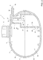
figure 2 is a cross-section along a vertical plane of the tank infigure 1 , shown in a simplified manner and with parts removed for clarity; -
figure 3 is a cross-section, on an enlarged scale, according to the plane III-III infigure 2 ; -
figure 4 shows, on an enlarged scale and in cross-section, an inlet mouth of the expansion tank and relates to an insert provided at said inlet mouth, according to a variant of what is shown infigure 3 ; and -
figure 5 shows, in cross-section, three inserts, having a different inner diameter from each other, which can be used at the inlet mouth infigure 4 . - In
figure 1 , reference numeral 1 denotes an expansion tank, forming part of a cooling system (not shown) which, in use, is placed in an engine compartment of a motor vehicle. Said system is configured so as to make a coolant fluid circulate to remove heat from an internal combustion engine (not shown). - The expansion tank 1 comprises a
shell 2, which is made of plastic material, is made in a single piece or multiple pieces, fixed to each other. InFigure 1 , a version is shown in which theshell 2 is composed of an upper half-shell 2a and a lower half-shell 2b. - As shown in a simplified manner and schematically in
figure 2 , theshell 2 comprises awall 4 defining a container, i.e. aninner cavity 5, suitable to receive and contain the coolant fluid. In particular, thewall 4 has, at an upper end, an opening closed by aremovable cap 6, to top-up the level of the coolant fluid in thecavity 5. The latter communicates with the remaining part of the cooling system through aninlet mouth 8 and an outlet mouth 9 (figure 1 ). Themouths - The
inlet mouth 8 is provided at aninlet collar 10, colloquially referred to as "filler", which constitutes part of theshell 2 and protrudes from thewall 4 outwards along anaxis 13. In the embodiment shown inFigure 4 , as will be better explained below, the inner surface of thecollar 10 defines an axial throughseat 15, which is engaged by atubular insert 16 coaxial with thecollar 10 and effectively defining themouth 8. - With reference to
figures 2 and3 , themouth 8 communicates with thecavity 5 through apassage 19 defined by atubular wall 20, which constitutes part of theshell 2, protrudes from an upper area of thewall 4 downwards inside thecavity 5, along a substantiallyvertical axis 21, and ends, at the bottom, with aportion 22 defining an outlet opening 23. - The
shell 2 further comprises atubular wall 24, which protrudes upwards from a lower area of thewall 4 in thecavity 5, i.e. towards thewall 20, and defines acompartment 25 which is aligned along theaxis 21 with thepassage 19. - The
wall 24 comprises alower end portion 26, adjacent to thewall 4, and anupper end portion 27, defining anoverflow opening 28. - The
portion 26 has ahole 29, which places thecompartment 25 in communication with the main part of thecavity 5, indicated byreference numeral 30. Thehole 29 keeps thecompartment 25, with the liquid arriving from themouth 8, i.e. from the engine and from the turbine, in communication with theremaining part 30, which must constantly provide the necessary flow of liquid to theoutlet mouth 9, so that it constantly levels the height of the liquid contained in thecompartment 25 and in theremaining part 30. - The outlet opening 23 is arranged, vertically, at a height that is less than or equal to that of the overflow opening 28. In particular, the outlet opening 23 is arranged at a lower height than that of the overflow opening 28, which is therefore engaged by the
portion 22 of thewall 20. - Preferably, the
overflow opening 28 is positioned at a height that is greater than or equal to a maximum reference level established at the design stage and corresponding to the maximum amount of coolant fluid which should be provided in thecavity 5. Normally, said reference level is represented by a notch, a protrusion or a symbol on thewall 4, to be easily identified visually for topping up the coolant fluid in the cooling system. - This way, the hot coolant fluid entering the tank 1 through the
mouth 8 flows into thepassage 19 and, from the latter, into thecompartment 25. From thecompartment 25, the liquid can reach themain part 30 of thecavity 5, even by overflowing through the overflow opening 28, as indicated by the arrows infigure 2 , as well as through thehole 29. It is therefore evident that thecompartment 25 defines a so-called stilling well, in that it reduces the turbulence of the flow coming out of thepassage 19. In other words, by overflowing, the liquid reaches themain part 30 of thecavity 5 in a relatively slow manner and with a limited fall. Moreover, thecompartment 25 improves the deaeration capacity of the coolant liquid in the tank 1. This way, the annoying gurgling sounds that can be heard immediately after stopping the engine are limited. - Preferably, as seen in
figure 3 , theportions radial spokes 31. In particular, the spaces between thespokes 31 define theoverflow opening 28. - Conveniently, as may be seen in
figures 1 and2 , thewall 20, thespokes 31 and theportion 27 constitute part of thesemi-shell 2a. At the same time, the lower edge of theportion 27 is fixed to the upper edge of theportion 26, which in turn constitutes part of the half-shell 2b. Conveniently, the attachment between the edges of theportions - The attachment between the
wall 20 and theportion 26 defines a structural stiffening of theshell 2, compared to the prior solutions, since it fastens the half-shells wall 4, but also inside thecavity 5. - Independently of the features of the structure defining the
compartment 25, with reference tofigure 4 it may be noted that theinsert 16 is held in a fixed axial position relative to thecollar 10 by a snap coupling. The insert comprises a tubular portion 35, preferably cylindrical, which engages theseat 15. In particular, the outer diameter of the portion 35 is equal to the inner diameter of thecollar 10, possibly without radial clearance and without interference. - The
insert 16 has a dual function, namely, the function of defining an inner stiffening for thecollar 10 to support the stresses; and the function of shielding thecollar 10 from the heat of the coolant liquid entering the tank 1 through themouth 8. - According to a preferred embodiment of the present invention, regardless of the features of the structure defining the
compartment 25, theinsert 16 is made in one piece in plastic material and is coloured in mass. - The plastic material of the
insert 16 makes it possible to have a relatively low heat conduction coefficient and to be able to obtain optimal flexibility and elasticity for the snap coupling. - At the same time, the mass pigmentation in the plastic material of the
insert 16 is used as a visual identification to provide corresponding information to the users, indicative of the internal diameter of theinsert 16. This way, it is possible to visually identify from the outside the transversal cross section of theinsert 16 and, thus, the maximum flow rate of the liquid entering the tank 1, defined at the design stage. - It is thus possible to standardise the manufacture of the
shell 2, such as shape and size, and obtain different tanks 1, i.e. suitable for different engines (petrol, diesel, of varying engine size etc.) and/or for different cooling systems. In fact, theshells 2 of the various tanks 1 are all made the same as each other. The mostsuitable insert 16 is then selected and fitted with an inner diameter established previously according to the required flow value, defined at the design stage for that type of cooling system and/or for that type of engine. As shown infigure 5 , theinserts - As a result, the various tanks can be recognised and distinguished from each other, during storage or during installation on the vehicle, by the colour of the
insert 16. In particular, in stock there will be a kit of tanks differing only in their inner diameter and, thus, by the colour of theinserts shell 2 which can be made on a larger scale. - From the above description with reference to
figures 1 to 3 , it is evident that the stilling well defined by thecompartment 26 makes it possible to limit the gurgling which is perceived normally immediately after stopping the engine due to the flow of liquid which tends to continue to enter the tank 1 and because of the steam in the liquid due to high temperatures. - The envisaged solution, thus alters the prior solutions in a negligible manner and makes it possible to achieve a stiffening of the
shell 2. - Regardless of the
compartment 25, the solution withinserts manner producing shells 2 equal to each other in shape and size. The recognition of the various tanks is then facilitated by the different colour of theinserts - From the above, lastly it appears evident that modifications and variations may be made to the expansion tank 1 described and illustrated while remaining within the sphere of protection of the present invention as defined in the appended claims.
- In particular, the
portions
Claims (2)
- Manufacturing process for making different expansion tanks for different cooling systems and/or for different engines of motor vehicles, each of said expansion tanks having an inlet mouth (8) and comprising:- a plastic shell (2) comprising:a) a wall (4) defining a cavity (5) for containing a coolant liquid;b) at least one collar (10) at said inlet mouth (8), said collar being outwardly projecting from said wall (4);- a tubular insert (16) engaging said collar (10) and defining said inlet mouth (8); said tubular insert (16) being made of plastic material;- retention means which hold said tubular insert (16) relative to said collar (10);characterised by:- making shells identical in shape and size, for all of said expansion tanks;- making tubular inserts (16) that differ in the value of their inner diameter; each inner diameter value being determined at the design stage depending on the type of cooling system and/or the type of engine;- selecting for each of said shells the most suitable tubular insert among the made tubular inserts; and- fitting the selected suitable tubular inserts in the collars of the corresponding shells.
- Process according to claim 10, characterised in that each said tubular insert is coloured in mass and in that each inner diameter value of said inserts is associated in a one to one manner with a corresponding colour.
Priority Applications (1)
| Application Number | Priority Date | Filing Date | Title |
|---|---|---|---|
| EP18182263.6A EP3406877B1 (en) | 2016-06-10 | 2016-06-10 | Manufacturing process for making different expansion tanks for different cooling systems and/or for different engines of motor vehicles |
Applications Claiming Priority (2)
| Application Number | Priority Date | Filing Date | Title |
|---|---|---|---|
| EP18182263.6A EP3406877B1 (en) | 2016-06-10 | 2016-06-10 | Manufacturing process for making different expansion tanks for different cooling systems and/or for different engines of motor vehicles |
| EP16425050.8A EP3255260B1 (en) | 2016-06-10 | 2016-06-10 | Expansion tank for a motor vehicle cooling system |
Related Parent Applications (2)
| Application Number | Title | Priority Date | Filing Date |
|---|---|---|---|
| EP16425050.8A Division-Into EP3255260B1 (en) | 2016-06-10 | 2016-06-10 | Expansion tank for a motor vehicle cooling system |
| EP16425050.8A Division EP3255260B1 (en) | 2016-06-10 | 2016-06-10 | Expansion tank for a motor vehicle cooling system |
Publications (2)
| Publication Number | Publication Date |
|---|---|
| EP3406877A1 true EP3406877A1 (en) | 2018-11-28 |
| EP3406877B1 EP3406877B1 (en) | 2021-04-14 |
Family
ID=56740994
Family Applications (2)
| Application Number | Title | Priority Date | Filing Date |
|---|---|---|---|
| EP16425050.8A Active EP3255260B1 (en) | 2016-06-10 | 2016-06-10 | Expansion tank for a motor vehicle cooling system |
| EP18182263.6A Active EP3406877B1 (en) | 2016-06-10 | 2016-06-10 | Manufacturing process for making different expansion tanks for different cooling systems and/or for different engines of motor vehicles |
Family Applications Before (1)
| Application Number | Title | Priority Date | Filing Date |
|---|---|---|---|
| EP16425050.8A Active EP3255260B1 (en) | 2016-06-10 | 2016-06-10 | Expansion tank for a motor vehicle cooling system |
Country Status (2)
| Country | Link |
|---|---|
| US (2) | US10690041B2 (en) |
| EP (2) | EP3255260B1 (en) |
Families Citing this family (6)
| Publication number | Priority date | Publication date | Assignee | Title |
|---|---|---|---|---|
| US11247144B2 (en) * | 2017-09-05 | 2022-02-15 | Novares Us Engine Components, Inc. | Vented degas bottle for motor vehicle coolant system |
| US12220981B2 (en) | 2021-04-27 | 2025-02-11 | Zhejiang Geely Holding Group Co., Ltd. | Expansion tanks for vehicle cooling systems and vehicle cooling systems |
| WO2023147089A1 (en) * | 2022-01-28 | 2023-08-03 | Taco, Inc. | Expansion tank with active flow manifold head |
| US12000323B2 (en) | 2022-10-07 | 2024-06-04 | Harley-Davidson Motor Company, Inc. | Coolant filler neck assembly having integrated coolant overflow reservoir |
| CN116398287B (en) * | 2023-03-28 | 2026-03-31 | 浙江银轮机械股份有限公司 | Full-flow expansion tank and cooling system |
| CN116591818B (en) * | 2023-05-06 | 2026-03-17 | 岚图汽车科技股份有限公司 | An integrated expansion tank for automobiles and automobiles |
Citations (4)
| Publication number | Priority date | Publication date | Assignee | Title |
|---|---|---|---|---|
| US5762130A (en) * | 1996-12-09 | 1998-06-09 | General Motors Corporation | Down flow, two pass radiator with air venting means |
| JP2002310377A (en) * | 2001-04-16 | 2002-10-23 | Nippon Soda Co Ltd | Sleeve with flange |
| US20060290137A1 (en) * | 2005-06-24 | 2006-12-28 | Zilmet S.P.A. | Threaded coupling for receptacles, such as expansion vessels, tanks and the like |
| WO2009113019A2 (en) | 2008-03-10 | 2009-09-17 | Land Rover | A cooling system expansion tank |
Family Cites Families (9)
| Publication number | Priority date | Publication date | Assignee | Title |
|---|---|---|---|---|
| DE4025067C1 (en) * | 1990-08-08 | 1991-07-11 | Mercedes-Benz Aktiengesellschaft, 7000 Stuttgart, De | |
| JP2002210810A (en) * | 2001-01-16 | 2002-07-31 | Kawasaki Heavy Ind Ltd | Blow molding method and molded article using the method |
| FR2841187B1 (en) * | 2002-06-21 | 2004-08-27 | Cf Gomma Spa | DEGASSING DEVICE AND METHOD FOR MOTOR VEHICLES |
| FR2866064B1 (en) * | 2004-02-11 | 2008-05-16 | Trelleborg Fluid Systems Geie | DEVICE FOR CONTROLLING THE LIQUID PHASE OF A COOLING CIRCUIT OF A THERMAL MOTOR, IN PARTICULAR FOR A MOTOR VEHICLE |
| FR2913374B1 (en) * | 2007-03-08 | 2009-04-10 | Itw Bailly Comte Soc Par Actio | COOLING SYSTEM OF A MOTOR VEHICLE, DEGASSING TANK AND CORRESPONDING MOTOR VEHICLE |
| FR2921419B1 (en) * | 2007-09-26 | 2010-03-12 | Trelleborg Fluid & Acoustic Solutions Tfas | DEGASSING BOX PROVIDED WITH A PLUNGER TUBE AND A TRANQUILIZATION CHAMBER |
| NL1036843A1 (en) * | 2008-05-23 | 2009-11-24 | Asml Netherlands Bv | Support structure, lithographic apparatus and method. |
| US8507020B2 (en) * | 2010-08-03 | 2013-08-13 | Columbus Manufacturing, Inc. | Gas flush high pressure pasteurization packaging and associated methods |
| EP3225806B1 (en) * | 2016-03-30 | 2018-07-04 | FCA Italy S.p.A. | Expansion tank for a motor-vehicle cooling system |
-
2016
- 2016-06-10 EP EP16425050.8A patent/EP3255260B1/en active Active
- 2016-06-10 EP EP18182263.6A patent/EP3406877B1/en active Active
-
2017
- 2017-06-08 US US15/617,624 patent/US10690041B2/en active Active
-
2019
- 2019-04-23 US US16/391,863 patent/US10837350B2/en active Active
Patent Citations (4)
| Publication number | Priority date | Publication date | Assignee | Title |
|---|---|---|---|---|
| US5762130A (en) * | 1996-12-09 | 1998-06-09 | General Motors Corporation | Down flow, two pass radiator with air venting means |
| JP2002310377A (en) * | 2001-04-16 | 2002-10-23 | Nippon Soda Co Ltd | Sleeve with flange |
| US20060290137A1 (en) * | 2005-06-24 | 2006-12-28 | Zilmet S.P.A. | Threaded coupling for receptacles, such as expansion vessels, tanks and the like |
| WO2009113019A2 (en) | 2008-03-10 | 2009-09-17 | Land Rover | A cooling system expansion tank |
Also Published As
| Publication number | Publication date |
|---|---|
| EP3255260A1 (en) | 2017-12-13 |
| US20190249592A1 (en) | 2019-08-15 |
| EP3255260B1 (en) | 2019-04-24 |
| US20170356328A1 (en) | 2017-12-14 |
| US10690041B2 (en) | 2020-06-23 |
| EP3406877B1 (en) | 2021-04-14 |
| US10837350B2 (en) | 2020-11-17 |
Similar Documents
| Publication | Publication Date | Title |
|---|---|---|
| US10837350B2 (en) | Method of making expansion tanks for cooling systems and/or engines | |
| US6491180B2 (en) | Fuel tank | |
| US9151256B2 (en) | Overfill prevention valve | |
| CN105612076B (en) | Working fluid container with integrated exhaust and/or intake valves | |
| US4366858A (en) | Self-deaerating heat exchanger for engine cooling circuits | |
| US4425877A (en) | Cooling arrangement for liquid cooled internal combustion engines | |
| US4231424A (en) | Header constituting a pressurizing tank | |
| US20100078094A1 (en) | Pour spout assembly with winged stop structure | |
| US9186979B2 (en) | Reservoir for reducing aeration of a fluid | |
| JPH10318065A (en) | Vent device for vehicle fuel tank | |
| US6119739A (en) | Easy-flow funnel | |
| US8485143B2 (en) | Valve arrangement for venting a coolant circuit of an internal combustion engine | |
| US4580622A (en) | Water box and expansion chamber device for a heat exchanger, in particular a radiator for a motor vehicle | |
| US5762130A (en) | Down flow, two pass radiator with air venting means | |
| US7188588B2 (en) | Cooling system and coolant reservoir for a cooling system | |
| CN108349380B (en) | Uncovered oil supply device and manufacturing method thereof | |
| US8561597B2 (en) | Flange for fuel pump module and manufacturing method thereof | |
| EP2513445A1 (en) | Coolant reservoir for an internal combustion engine | |
| CA2713056A1 (en) | De-aerating flow straightener for cooling system | |
| US20180155175A1 (en) | Radiator funnel assembly with unique identifiers | |
| EP0687547A2 (en) | Container | |
| US10151232B2 (en) | Storage tank | |
| JP2010173467A (en) | Ventilation control valve | |
| CN105599836A (en) | Fuel tank and manufacturing method thereof | |
| JP4135166B2 (en) | Filament neck structure of radiator |
Legal Events
| Date | Code | Title | Description |
|---|---|---|---|
| PUAI | Public reference made under article 153(3) epc to a published international application that has entered the european phase |
Free format text: ORIGINAL CODE: 0009012 |
|
| STAA | Information on the status of an ep patent application or granted ep patent |
Free format text: STATUS: THE APPLICATION HAS BEEN PUBLISHED |
|
| STAA | Information on the status of an ep patent application or granted ep patent |
Free format text: STATUS: REQUEST FOR EXAMINATION WAS MADE |
|
| AC | Divisional application: reference to earlier application |
Ref document number: 3255260 Country of ref document: EP Kind code of ref document: P |
|
| AK | Designated contracting states |
Kind code of ref document: A1 Designated state(s): AL AT BE BG CH CY CZ DE DK EE ES FI FR GB GR HR HU IE IS IT LI LT LU LV MC MK MT NL NO PL PT RO RS SE SI SK SM TR |
|
| AX | Request for extension of the european patent |
Extension state: BA ME |
|
| 17P | Request for examination filed |
Effective date: 20181115 |
|
| RBV | Designated contracting states (corrected) |
Designated state(s): AL AT BE BG CH CY CZ DE DK EE ES FI FR GB GR HR HU IE IS IT LI LT LU LV MC MK MT NL NO PL PT RO RS SE SI SK SM TR |
|
| STAA | Information on the status of an ep patent application or granted ep patent |
Free format text: STATUS: EXAMINATION IS IN PROGRESS |
|
| 17Q | First examination report despatched |
Effective date: 20200527 |
|
| GRAP | Despatch of communication of intention to grant a patent |
Free format text: ORIGINAL CODE: EPIDOSNIGR1 |
|
| STAA | Information on the status of an ep patent application or granted ep patent |
Free format text: STATUS: GRANT OF PATENT IS INTENDED |
|
| INTG | Intention to grant announced |
Effective date: 20201106 |
|
| GRAS | Grant fee paid |
Free format text: ORIGINAL CODE: EPIDOSNIGR3 |
|
| GRAA | (expected) grant |
Free format text: ORIGINAL CODE: 0009210 |
|
| STAA | Information on the status of an ep patent application or granted ep patent |
Free format text: STATUS: THE PATENT HAS BEEN GRANTED |
|
| AC | Divisional application: reference to earlier application |
Ref document number: 3255260 Country of ref document: EP Kind code of ref document: P |
|
| AK | Designated contracting states |
Kind code of ref document: B1 Designated state(s): AL AT BE BG CH CY CZ DE DK EE ES FI FR GB GR HR HU IE IS IT LI LT LU LV MC MK MT NL NO PL PT RO RS SE SI SK SM TR |
|
| REG | Reference to a national code |
Ref country code: GB Ref legal event code: FG4D |
|
| REG | Reference to a national code |
Ref country code: CH Ref legal event code: EP |
|
| REG | Reference to a national code |
Ref country code: DE Ref legal event code: R096 Ref document number: 602016056327 Country of ref document: DE |
|
| REG | Reference to a national code |
Ref country code: IE Ref legal event code: FG4D |
|
| REG | Reference to a national code |
Ref country code: AT Ref legal event code: REF Ref document number: 1382573 Country of ref document: AT Kind code of ref document: T Effective date: 20210515 |
|
| REG | Reference to a national code |
Ref country code: LT Ref legal event code: MG9D |
|
| REG | Reference to a national code |
Ref country code: AT Ref legal event code: MK05 Ref document number: 1382573 Country of ref document: AT Kind code of ref document: T Effective date: 20210414 |
|
| REG | Reference to a national code |
Ref country code: NL Ref legal event code: MP Effective date: 20210414 |
|
| PG25 | Lapsed in a contracting state [announced via postgrant information from national office to epo] |
Ref country code: LT Free format text: LAPSE BECAUSE OF FAILURE TO SUBMIT A TRANSLATION OF THE DESCRIPTION OR TO PAY THE FEE WITHIN THE PRESCRIBED TIME-LIMIT Effective date: 20210414 Ref country code: HR Free format text: LAPSE BECAUSE OF FAILURE TO SUBMIT A TRANSLATION OF THE DESCRIPTION OR TO PAY THE FEE WITHIN THE PRESCRIBED TIME-LIMIT Effective date: 20210414 Ref country code: FI Free format text: LAPSE BECAUSE OF FAILURE TO SUBMIT A TRANSLATION OF THE DESCRIPTION OR TO PAY THE FEE WITHIN THE PRESCRIBED TIME-LIMIT Effective date: 20210414 Ref country code: NL Free format text: LAPSE BECAUSE OF FAILURE TO SUBMIT A TRANSLATION OF THE DESCRIPTION OR TO PAY THE FEE WITHIN THE PRESCRIBED TIME-LIMIT Effective date: 20210414 Ref country code: BG Free format text: LAPSE BECAUSE OF FAILURE TO SUBMIT A TRANSLATION OF THE DESCRIPTION OR TO PAY THE FEE WITHIN THE PRESCRIBED TIME-LIMIT Effective date: 20210714 Ref country code: AT Free format text: LAPSE BECAUSE OF FAILURE TO SUBMIT A TRANSLATION OF THE DESCRIPTION OR TO PAY THE FEE WITHIN THE PRESCRIBED TIME-LIMIT Effective date: 20210414 |
|
| PG25 | Lapsed in a contracting state [announced via postgrant information from national office to epo] |
Ref country code: RS Free format text: LAPSE BECAUSE OF FAILURE TO SUBMIT A TRANSLATION OF THE DESCRIPTION OR TO PAY THE FEE WITHIN THE PRESCRIBED TIME-LIMIT Effective date: 20210414 Ref country code: SE Free format text: LAPSE BECAUSE OF FAILURE TO SUBMIT A TRANSLATION OF THE DESCRIPTION OR TO PAY THE FEE WITHIN THE PRESCRIBED TIME-LIMIT Effective date: 20210414 Ref country code: LV Free format text: LAPSE BECAUSE OF FAILURE TO SUBMIT A TRANSLATION OF THE DESCRIPTION OR TO PAY THE FEE WITHIN THE PRESCRIBED TIME-LIMIT Effective date: 20210414 Ref country code: PL Free format text: LAPSE BECAUSE OF FAILURE TO SUBMIT A TRANSLATION OF THE DESCRIPTION OR TO PAY THE FEE WITHIN THE PRESCRIBED TIME-LIMIT Effective date: 20210414 Ref country code: PT Free format text: LAPSE BECAUSE OF FAILURE TO SUBMIT A TRANSLATION OF THE DESCRIPTION OR TO PAY THE FEE WITHIN THE PRESCRIBED TIME-LIMIT Effective date: 20210816 Ref country code: NO Free format text: LAPSE BECAUSE OF FAILURE TO SUBMIT A TRANSLATION OF THE DESCRIPTION OR TO PAY THE FEE WITHIN THE PRESCRIBED TIME-LIMIT Effective date: 20210714 Ref country code: GR Free format text: LAPSE BECAUSE OF FAILURE TO SUBMIT A TRANSLATION OF THE DESCRIPTION OR TO PAY THE FEE WITHIN THE PRESCRIBED TIME-LIMIT Effective date: 20210715 Ref country code: IS Free format text: LAPSE BECAUSE OF FAILURE TO SUBMIT A TRANSLATION OF THE DESCRIPTION OR TO PAY THE FEE WITHIN THE PRESCRIBED TIME-LIMIT Effective date: 20210814 |
|
| REG | Reference to a national code |
Ref country code: DE Ref legal event code: R097 Ref document number: 602016056327 Country of ref document: DE |
|
| PG25 | Lapsed in a contracting state [announced via postgrant information from national office to epo] |
Ref country code: ES Free format text: LAPSE BECAUSE OF FAILURE TO SUBMIT A TRANSLATION OF THE DESCRIPTION OR TO PAY THE FEE WITHIN THE PRESCRIBED TIME-LIMIT Effective date: 20210414 Ref country code: EE Free format text: LAPSE BECAUSE OF FAILURE TO SUBMIT A TRANSLATION OF THE DESCRIPTION OR TO PAY THE FEE WITHIN THE PRESCRIBED TIME-LIMIT Effective date: 20210414 Ref country code: SM Free format text: LAPSE BECAUSE OF FAILURE TO SUBMIT A TRANSLATION OF THE DESCRIPTION OR TO PAY THE FEE WITHIN THE PRESCRIBED TIME-LIMIT Effective date: 20210414 Ref country code: SK Free format text: LAPSE BECAUSE OF FAILURE TO SUBMIT A TRANSLATION OF THE DESCRIPTION OR TO PAY THE FEE WITHIN THE PRESCRIBED TIME-LIMIT Effective date: 20210414 Ref country code: RO Free format text: LAPSE BECAUSE OF FAILURE TO SUBMIT A TRANSLATION OF THE DESCRIPTION OR TO PAY THE FEE WITHIN THE PRESCRIBED TIME-LIMIT Effective date: 20210414 Ref country code: MC Free format text: LAPSE BECAUSE OF FAILURE TO SUBMIT A TRANSLATION OF THE DESCRIPTION OR TO PAY THE FEE WITHIN THE PRESCRIBED TIME-LIMIT Effective date: 20210414 Ref country code: CZ Free format text: LAPSE BECAUSE OF FAILURE TO SUBMIT A TRANSLATION OF THE DESCRIPTION OR TO PAY THE FEE WITHIN THE PRESCRIBED TIME-LIMIT Effective date: 20210414 Ref country code: DK Free format text: LAPSE BECAUSE OF FAILURE TO SUBMIT A TRANSLATION OF THE DESCRIPTION OR TO PAY THE FEE WITHIN THE PRESCRIBED TIME-LIMIT Effective date: 20210414 |
|
| REG | Reference to a national code |
Ref country code: CH Ref legal event code: PL |
|
| PLBE | No opposition filed within time limit |
Free format text: ORIGINAL CODE: 0009261 |
|
| STAA | Information on the status of an ep patent application or granted ep patent |
Free format text: STATUS: NO OPPOSITION FILED WITHIN TIME LIMIT |
|
| REG | Reference to a national code |
Ref country code: BE Ref legal event code: MM Effective date: 20210630 |
|
| 26N | No opposition filed |
Effective date: 20220117 |
|
| GBPC | Gb: european patent ceased through non-payment of renewal fee |
Effective date: 20210714 |
|
| PG25 | Lapsed in a contracting state [announced via postgrant information from national office to epo] |
Ref country code: LU Free format text: LAPSE BECAUSE OF NON-PAYMENT OF DUE FEES Effective date: 20210610 |
|
| PG25 | Lapsed in a contracting state [announced via postgrant information from national office to epo] |
Ref country code: LI Free format text: LAPSE BECAUSE OF NON-PAYMENT OF DUE FEES Effective date: 20210630 Ref country code: IE Free format text: LAPSE BECAUSE OF NON-PAYMENT OF DUE FEES Effective date: 20210610 Ref country code: GB Free format text: LAPSE BECAUSE OF NON-PAYMENT OF DUE FEES Effective date: 20210714 Ref country code: CH Free format text: LAPSE BECAUSE OF NON-PAYMENT OF DUE FEES Effective date: 20210630 |
|
| PG25 | Lapsed in a contracting state [announced via postgrant information from national office to epo] |
Ref country code: IS Free format text: LAPSE BECAUSE OF FAILURE TO SUBMIT A TRANSLATION OF THE DESCRIPTION OR TO PAY THE FEE WITHIN THE PRESCRIBED TIME-LIMIT Effective date: 20210814 Ref country code: AL Free format text: LAPSE BECAUSE OF FAILURE TO SUBMIT A TRANSLATION OF THE DESCRIPTION OR TO PAY THE FEE WITHIN THE PRESCRIBED TIME-LIMIT Effective date: 20210414 |
|
| PG25 | Lapsed in a contracting state [announced via postgrant information from national office to epo] |
Ref country code: BE Free format text: LAPSE BECAUSE OF NON-PAYMENT OF DUE FEES Effective date: 20210630 |
|
| PG25 | Lapsed in a contracting state [announced via postgrant information from national office to epo] |
Ref country code: CY Free format text: LAPSE BECAUSE OF FAILURE TO SUBMIT A TRANSLATION OF THE DESCRIPTION OR TO PAY THE FEE WITHIN THE PRESCRIBED TIME-LIMIT Effective date: 20210414 |
|
| PG25 | Lapsed in a contracting state [announced via postgrant information from national office to epo] |
Ref country code: HU Free format text: LAPSE BECAUSE OF FAILURE TO SUBMIT A TRANSLATION OF THE DESCRIPTION OR TO PAY THE FEE WITHIN THE PRESCRIBED TIME-LIMIT; INVALID AB INITIO Effective date: 20160610 |
|
| PG25 | Lapsed in a contracting state [announced via postgrant information from national office to epo] |
Ref country code: MK Free format text: LAPSE BECAUSE OF FAILURE TO SUBMIT A TRANSLATION OF THE DESCRIPTION OR TO PAY THE FEE WITHIN THE PRESCRIBED TIME-LIMIT Effective date: 20210414 |
|
| PG25 | Lapsed in a contracting state [announced via postgrant information from national office to epo] |
Ref country code: MT Free format text: LAPSE BECAUSE OF FAILURE TO SUBMIT A TRANSLATION OF THE DESCRIPTION OR TO PAY THE FEE WITHIN THE PRESCRIBED TIME-LIMIT Effective date: 20210414 |
|
| PGFP | Annual fee paid to national office [announced via postgrant information from national office to epo] |
Ref country code: DE Payment date: 20250520 Year of fee payment: 10 |
|
| PGFP | Annual fee paid to national office [announced via postgrant information from national office to epo] |
Ref country code: IT Payment date: 20250520 Year of fee payment: 10 |
|
| PGFP | Annual fee paid to national office [announced via postgrant information from national office to epo] |
Ref country code: FR Payment date: 20250520 Year of fee payment: 10 |
|
| PG25 | Lapsed in a contracting state [announced via postgrant information from national office to epo] |
Ref country code: TR Free format text: LAPSE BECAUSE OF FAILURE TO SUBMIT A TRANSLATION OF THE DESCRIPTION OR TO PAY THE FEE WITHIN THE PRESCRIBED TIME-LIMIT Effective date: 20210414 |
|
| REG | Reference to a national code |
Ref country code: DE Ref legal event code: R081 Ref document number: 602016056327 Country of ref document: DE Owner name: STELLANTIS EUROPE S.P.A., IT Free format text: FORMER OWNER: FCA ITALY S.P.A., TORINO, IT |