EP3406815A1 - Construction system - Google Patents
Construction system Download PDFInfo
- Publication number
- EP3406815A1 EP3406815A1 EP18171281.1A EP18171281A EP3406815A1 EP 3406815 A1 EP3406815 A1 EP 3406815A1 EP 18171281 A EP18171281 A EP 18171281A EP 3406815 A1 EP3406815 A1 EP 3406815A1
- Authority
- EP
- European Patent Office
- Prior art keywords
- construction
- plate
- construction element
- end portion
- reinforcement
- Prior art date
- Legal status (The legal status is an assumption and is not a legal conclusion. Google has not performed a legal analysis and makes no representation as to the accuracy of the status listed.)
- Granted
Links
Images




Classifications
-
- E—FIXED CONSTRUCTIONS
- E04—BUILDING
- E04B—GENERAL BUILDING CONSTRUCTIONS; WALLS, e.g. PARTITIONS; ROOFS; FLOORS; CEILINGS; INSULATION OR OTHER PROTECTION OF BUILDINGS
- E04B1/00—Constructions in general; Structures which are not restricted either to walls, e.g. partitions, or floors or ceilings or roofs
- E04B1/38—Connections for building structures in general
- E04B1/61—Connections for building structures in general of slab-shaped building elements with each other
- E04B1/6108—Connections for building structures in general of slab-shaped building elements with each other the frontal surfaces of the slabs connected together
- E04B1/612—Connections for building structures in general of slab-shaped building elements with each other the frontal surfaces of the slabs connected together by means between frontal surfaces
- E04B1/6125—Connections for building structures in general of slab-shaped building elements with each other the frontal surfaces of the slabs connected together by means between frontal surfaces with protrusions on the one frontal surface co-operating with recesses in the other frontal surface
- E04B1/6141—Connections for building structures in general of slab-shaped building elements with each other the frontal surfaces of the slabs connected together by means between frontal surfaces with protrusions on the one frontal surface co-operating with recesses in the other frontal surface the connection made by an additional locking key
-
- E—FIXED CONSTRUCTIONS
- E04—BUILDING
- E04B—GENERAL BUILDING CONSTRUCTIONS; WALLS, e.g. PARTITIONS; ROOFS; FLOORS; CEILINGS; INSULATION OR OTHER PROTECTION OF BUILDINGS
- E04B1/00—Constructions in general; Structures which are not restricted either to walls, e.g. partitions, or floors or ceilings or roofs
- E04B1/02—Structures consisting primarily of load-supporting, block-shaped, or slab-shaped elements
- E04B1/14—Structures consisting primarily of load-supporting, block-shaped, or slab-shaped elements the elements being composed of two or more materials
-
- E—FIXED CONSTRUCTIONS
- E04—BUILDING
- E04B—GENERAL BUILDING CONSTRUCTIONS; WALLS, e.g. PARTITIONS; ROOFS; FLOORS; CEILINGS; INSULATION OR OTHER PROTECTION OF BUILDINGS
- E04B1/00—Constructions in general; Structures which are not restricted either to walls, e.g. partitions, or floors or ceilings or roofs
- E04B1/62—Insulation or other protection; Elements or use of specified material therefor
- E04B1/74—Heat, sound or noise insulation, absorption, or reflection; Other building methods affording favourable thermal or acoustical conditions, e.g. accumulating of heat within walls
- E04B1/76—Heat, sound or noise insulation, absorption, or reflection; Other building methods affording favourable thermal or acoustical conditions, e.g. accumulating of heat within walls specifically with respect to heat only
- E04B1/78—Heat insulating elements
- E04B1/80—Heat insulating elements slab-shaped
-
- E—FIXED CONSTRUCTIONS
- E04—BUILDING
- E04C—STRUCTURAL ELEMENTS; BUILDING MATERIALS
- E04C2/00—Building elements of relatively thin form for the construction of parts of buildings, e.g. sheet materials, slabs, or panels
- E04C2/02—Building elements of relatively thin form for the construction of parts of buildings, e.g. sheet materials, slabs, or panels characterised by specified materials
- E04C2/26—Building elements of relatively thin form for the construction of parts of buildings, e.g. sheet materials, slabs, or panels characterised by specified materials composed of materials covered by two or more of groups E04C2/04, E04C2/08, E04C2/10 or of materials covered by one of these groups with a material not specified in one of the groups
- E04C2/284—Building elements of relatively thin form for the construction of parts of buildings, e.g. sheet materials, slabs, or panels characterised by specified materials composed of materials covered by two or more of groups E04C2/04, E04C2/08, E04C2/10 or of materials covered by one of these groups with a material not specified in one of the groups at least one of the materials being insulating
- E04C2/292—Building elements of relatively thin form for the construction of parts of buildings, e.g. sheet materials, slabs, or panels characterised by specified materials composed of materials covered by two or more of groups E04C2/04, E04C2/08, E04C2/10 or of materials covered by one of these groups with a material not specified in one of the groups at least one of the materials being insulating composed of insulating material and sheet metal
-
- E—FIXED CONSTRUCTIONS
- E04—BUILDING
- E04C—STRUCTURAL ELEMENTS; BUILDING MATERIALS
- E04C2/00—Building elements of relatively thin form for the construction of parts of buildings, e.g. sheet materials, slabs, or panels
- E04C2002/001—Mechanical features of panels
- E04C2002/004—Panels with profiled edges, e.g. stepped, serrated
Definitions
- the present invention relates to a construction system suitable for being used in building constructions.
- the present invention more particularly relates to a construction system that is easy to mount and eliminates the risk of rot and moulds growth.
- modules are typically called sandwich panels and may comprise expanded foam such as polyurethane (PUR) or polyisocyanurate (PIR) sandwiched between steel plates.
- PUR polyurethane
- PIR polyisocyanurate
- the construction system according to the invention is a construction system comprising two adjacent construction elements, wherein each construction element comprises a core structure comprising an insulation material sandwiched between a first reinforcement structure and a second reinforcement structure, wherein a first plate is attached to the first reinforcement structure and wherein a second plate is attached to the second reinforcement structure, wherein the two adjacent construction elements are mechanically attached to each other by means of attachment members in a region of overlap.
- the mounting procedure is eased and can be done much faster by using the construction system according to the invention than the prior art panels.
- the adjacent construction elements can be firmly attached to each other.
- Each construction element has a core structure comprising an insulation material sandwiched between a first reinforcement structure and a second reinforcement structure.
- the insulation material is preferably made of PUR or PIR.
- the first plate is attached to the outside surface of the first reinforcement structure and the second plate is attached to the outside surface of the second reinforcement structure may be any suitable type of plate that can provide the required load-bearing capacity of the construction element. It is, however, preferred that the first plate and/or the second plate is made in a fire-resistant material.
- region of overlap is meant a region, in which there is overlap between adjacent construction elements.
- An overlap may be provided in a protruding structure of one of the construction elements is received by a corresponding receiving structure of the other construction element.
- the attachment members are screws or nails. It may be an advantage to apply attachment members, preferably screws or nails formed in a fire-resistant material or nails. Hereby, displacement of the adjacent construction elements due to high temperatures (e.g. during a fire) can be prevented. Accordingly, the invention provides a fire-resistant construction system.
- the attachment members are arranged in a configuration extending along a zone being parallel to a joint of the adjacent construction elements, wherein the zone is arranged in a non-zero distance from the from the joint.
- the attachment members are inserted in areas, in which they penetrate a first structure of a first construction element and a first structure of a second adjacent construction element so that a firm attachment of the adjacent construction elements.
- said distance is in the range 3-50 mm. In one embodiment, said distance is in the range 5-30 mm, such as 6-20 mm. In one embodiment, the distance is approximately 10 mm.
- the attachment members extend along a line extending parallel to the joint.
- the fixation of the adjacent construction elements can be eased.
- it can be ensured that the attachment members are inserted into the most optimum structures of the construction system.
- the attachment members penetrate a first structure of a first construction element, a first structure of a second adjacent construction element and a second structure of a first construction element.
- a reliable and firm attachment of the adjacent structures can be achieved.
- attachment members penetrate a first structure of a first construction element, a first structure of a second adjacent construction element, a second structure of a first construction element and a second structure of the second construction element.
- first structure of a first construction element a first structure of a second adjacent construction element
- second structure of a first construction element a second structure of the second construction element
- the glue may preferably be an inorganic glue.
- the glue preferably comprises a ductile adhesive.
- the glue preferably ensures a degree of adherence (quality of adhering) equal or greater than the degree of adherence of the insulation material.
- a mechanical attachment member e.g. a screw or a nail
- the use of glue makes it possible to achieve a large contact surface and to prevent pockets of air between the reinforcement structures and the plates attached thereto.
- first plate and/or the second plate are attached to the reinforcement structures by means of mechanical attachment members.
- the mechanical attachment members may be screws, nails or corresponding mechanical structures provided in the reinforcement structures and the plates.
- the first plate and/or the plate is a cement board.
- the first plate and/or the plate is a cement board.
- the insulation material comprises PUR or PIR.
- PUR physical property
- the insulation material is made in PUR or PIR. It may be advantageous that the core structure is made by moulding an insulation material made in PUR or PIR between the reinforcement structures.
- the plates may be attached to the core structure before or after the cutting process.
- first reinforcement structure and/or the second reinforcement structure is made of metal.
- the reinforcement structures may preferably be made in steel.
- the reinforcement structures are made in stainless steel.
- first reinforcement structure and/or the second reinforcement structure is shaped as corrugated plates.
- corrugated plates it is possible to enhance the mechanical properties of the reinforcement plates.
- corrugated plates it is possible to enhance the bending stiffness and torsional rigidity of the plates.
- the first reinforcement structure and/or the second reinforcement structure is made as a trapezoid plate.
- the construction element comprises a first end portion and a corresponding second end portion, wherein the first end portion comprises one or more protruding structures configured to be received by corresponding receiving structures provided in the second end portion.
- the construction element comprises a first end portion and a corresponding second end portion, wherein the second end portion comprises one or more male portions configured to be received by corresponding female portions provided in the first end portion.
- the second end portion comprises one or more male portions configured to be received by corresponding female portions provided in the first end portion.
- the construction element comprises a plane end portion.
- a corner structure of a domestic building such as a family house.
- the construction element comprises a cutaway provided in the top portion of the construction element.
- a wall plate in the cutaway.
- it is possibly to attach rafters of a roof construction to the wall plate.
- the cutaway portion is configured to receive a box-shaped elongated wall plate.
- the cutaway portion may have a box-shaped geometry having a longitudinal axis that extends parallel to the longitudinal axis X of the construction element.
- the construction element is constructed in such a manner that a gap is provided between the insulation material of adjacent construction elements when the construction elements bear against (abut) each other.
- a gap is provided between the insulation material of adjacent construction elements when the construction elements bear against (abut) each other.
- a construction element 2 of the present invention is illustrated in Fig. 1A .
- Fig. 1A illustrates a schematic, cross-sectional view of a construction element 2 of a connection system according to the invention, wherein the construction element 2 is in a non-assembled configuration.
- the construction element 2 comprises a core structure 3 comprising an insulation material 8 sandwiched between a first reinforcement structure 6 and a second first reinforcement structure 6'.
- the first reinforcement structure 6 is attached to the opposite side of the insulation material 8 than the second reinforcement structure 6'.
- the insulation material 8 may be an expanded foam such as PUR or PIR.
- the construction element 2 comprises a core structure 3, a first plate 4 (inner plate) and a second plate 4' (outer plate) that have not yet been attached to the sandwiched core structure 3.
- Fig. 1B illustrates a schematic, cross-sectional view of the construction element 2 shown in Fig. 1A in an assembled configuration.
- the first plate 4 and the second outer plate 4' are preferably made of a fire-resistant material.
- a fire-resistant material may be a cement board comprising cement and reinforcing fibres. It is possible to replace one of the plates 4, 4' with a plate made in another material.
- the construction element 2 comprises a core structure 3, a first cement board plate 4 (inner plate) and a second cement board plate 4' (outer plate), wherein both the first plate 4 and the second plate 4' have been attached to the sandwiched core structure 3.
- the glue may preferably be a flexible and ductile glue.
- the first plate 4 and the second plate 4' can be attached to the sandwiched core structure 3 by means of mechanical attachment elements.
- the first reinforcement structure 6 and the second reinforcement structure 6' are corrugated plates.
- the first reinforcement structure 6 and the second reinforcement structure 6' are steel plates.
- a plurality of spaces 10, 10' are provided between the reinforcement structures 6, 6' and the plates 4, 4' attached thereto.
- the plates 4, 4' are attached to only the outwardly facing plane structures of the reinforcement structures 6, 6'. Accordingly, a portion of the reinforcement structures 6, 6' is not in contact with the plates 4, 4'.
- the core structure 3 can be manufactured by using a lamination process, e.g. a PUR laminating line in which PUR or PIR is injected into a space defined by two steel reinforcement structures. Afterwards, when the PUR or PIR has hardened, the product may be cut into predefined modules (core structures). Hereafter, the plates 4, 4' can be attached to the modules (core structures) and the construction element is ready to be used. It may be an advantage to provide end portions having specific (e.g. matching) geometries to make it easy and safe to transport, store and join the modules (core structures).
- the construction element 2 according to the invention may be used in building constructions.
- the use of construction elements 2 according to the invention may reduce the construction time and ease the mounting process.
- the construction elements 2 can be made in inorganic material, the risk of rot and moulds growth on building materials may be reduced or even eliminated.
- the thickness T 3 of the insulation material 8 is larger than the thickness T 2 of the plates 4, 4'. Furthermore, the thickness T 2 of the plates 4, 4' is larger than the thickness T 1 of the reinforcement structures 6, 6'.
- the thickness T 3 of the insulation material 8 is in the range 100-400 mm, preferably 150-300 mm such as approximately 200 mm, whereas the thickness T 2 of the plates 4, 4' is approximately 5-30 mm, preferably 10-20 mm such as 6 mm.
- the thickness T 1 of the reinforcement structures 6, 6' may be in the range 3-30 mm, preferably 5-10 mm such as 6 mm.
- Fig. 2A illustrates a schematic, perspective top view of a first construction element 2 attached to a second construction element 2'.
- the construction forms a corner portion 12.
- the first construction element 2 comprises an insulation material 8 sandwiched between two metal reinforcement plates 6, 6' that preferably are made of corrugated steel.
- a boxed-shaped outer cement board plate 4 is glued to the outside surface of the reinforcement plate 6, whereas another boxed-shaped outer cement board plate 4 is glued to the outside surface of the other reinforcement plate 6'.
- the first construction element 2 comprises a first end portion 16 shaped to engage with a corresponding end portion shaped as the second end portion 18 of the second construction element 2'.
- the first construction element 2 comprises a second plane end portion 20 provided in the opposite end than the first end portion 16.
- the second construction element 2' comprises a plane end portion 20 provided in the opposite end than the second end portion 18.
- the plane end portion 20 abuts the plate 4' of the first construction element 2.
- the second construction element 2' comprises an insulation material 8 sandwiched between two metal reinforcement plates 6, 6', preferably corrugated steel reinforcement plates 6, 6'.
- a boxed-shaped outer cement board plate 4 is glued to the outside surface of the reinforcement plate 6, whereas another boxed-shaped outer cement board plate 4 is glued to the outside surface of the other reinforcement plate 6'.
- the first construction element 2 and the second construction element 2' are angled 90 degrees relative to each other.
- a bracket 14 like the one shown in Fig. 2A may be attached to the inside plates 4' of the first construction element 2 and the second construction element 2' for improving the mechanical strength of the corner portion 12.
- the bracket 14 may be screwed or nailed into the construction elements 2, 2' or alternative attached by means of glue.
- Fig. 2B illustrates a schematic, top view of two construction elements 2, 2' according to the invention attached to each other and hereby constitution a corner portion 12.
- the first construction element 2 comprises an insulation material 8 sandwiched between two metal reinforcement plates 6, 6'.
- a boxed-shaped outer cement board plate 4 is attached to the outside surface of the reinforcement plate 6, whereas another boxed-shaped outer cement board plate 4 is glued to the outside surface of the other reinforcement plate 6'.
- the first construction element 2 comprises a plane end portion 20 abutting the inside portion of the outer plate 4 of the second construction element 2'.
- the second construction element 2' comprises a plane end portion 20 that abuts the plate 4' of the first construction element 2.
- the second construction element 2' comprises an insulation material 8 sandwiched between two steel reinforcement plates 6, 6'.
- a boxed-shaped outer cement board plate 4 is glued to the outside surface of the reinforcement plate 6, whereas another boxed-shaped outer cement board plate 4 is glued to the outside surface of the other reinforcement plate 6'.
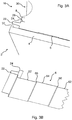
- Fig. 3A illustrates a schematic, perspective view of a first end portion 16 of a construction element 2 according to the invention.
- the construction element 2 comprises an insulation material 8 provided at the inside of a steel trapezoid plate 6.
- the steel trapezoid plate 6 is provided with an end section comprising a protruding structure having a conical shape (being thinnest at the distal end) and an L-shaped portion 24 extending in extension of the protruding structure 22.
- a receiving portion 32 is provided next to the protruding structure 22.
- a cement board 4 is attached to the protruding outside surfaces of the trapezoid plate 6. The attachment may be carried out by using glue or mechanical attachment means (such as nails or screws). The end portion of the cement board 4 is aligned with the distal portion of the protruding structure 22.
- a cavity 30 is provided in the insulation material 8 at the end portion 16. A plane portion 28 is provide next to the cavity 30. The cavity 30 is configured to receive a corresponding male portion 36 (see Fig. 5A ).
- Fig. 3B illustrates a schematic, perspective of a section of a reinforcement structure 6 corresponding to the one shown in Fig. 3A .
- the reinforcement structure 6 comprises front portions 62 (that abut the outer plate shown in Fig. 3A ) provided between rear portions 64 (that are not in contact with the outer plate shown in Fig. 3A ) extending parallel to the portions 62.
- Connection structures 66, 66' connects adjacent front portions 62 and rear portions 64.
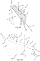
- Fig. 4A illustrates a schematic, perspective view of a top portion of a construction element 2 according to the invention.
- the construction element 2 comprises an insulation material 8.
- a cutaway portion 58 is provided in the top portion of the insulation material 8, preferably made an expanded foam such as PUR or PIR.
- the cutaway portion 58 is configured to receive a wall plate (not shown) onto which the rafter of a roof construction can be attached.
- the cutaway portion 58 has a box-shaped geometry having a longitudinal axis that extends parallel to the longitudinal axis X of the construction element 2.
- the construction element 2 has a transversal axis Y and a lateral axis Z.
- the construction element 2 comprises a core structure having an insulation material 8 sandwiched between a first reinforcement structure 6 and a second first reinforcement structure 6', wherein the first reinforcement structure 6 is attached to the opposite side of the insulation material 8 than the second reinforcement structure 6'.
- the reinforcement structures 6, 6' are preferably made of corrugated steel plates.
- the first plate 4 and the second plate 4' are preferably made of a fire-resistant material, preferably cement board.
- the construction element 2 comprises a first end portion 16 and a second end portion 18.
- the first end portion 16 is configured and shaped to engage with the corresponding second end portion 18 of the second construction element 2.
- Fig. 4B illustrates a schematic, perspective top view of a construction system 5 according to the invention.
- the construction system 5 comprises two joint construction elements 2, 2'.
- Each of the two joint construction elements 2, 2' basically corresponds to the one shown in Fig. 4A , however, no cutaway portion 58 is provided in the construction elements 2, 2'.
- the first construction element 2 comprises a first end portion and a second end portion 18, whereas the second construction element 2' comprises a first end portion 16 and a second end portion.
- the first end portion of the first construction element 2 abuts the second end portion of the second construction element 2'.
- the first construction element 2 and the second construction element 2' are joint in a joint portion 36 comprising a joint 46 extending along the transversal axis Y of the construction elements 2, 2'.
- the longitudinal axis X and the lateral axis Z of the construction elements 2, 2' are shown.
- both construction elements 2, 2' comprise an insulation material 8 sandwiched between two corrugated steel reinforcement plates 6, 6' and plates 4, 4' attached to the outside surface of the reinforcement plates 6, 6'.
- the construction elements 2, 2' are joint in a joint portion 34 that comprises a joint 46 extending along the transversal axis Y of the construction element 2'.
- Fig. 5A illustrates a schematic, perspective view of the joint portion 34 comprising a connection portion 38 of a construction system 5 comprising two adjacent construction elements 2, 2'.
- Each construction element 2, 2' comprises an insulation material 8 sandwiched between two reinforcement plates 6, 6'. Plates made of cement boards 4, 4' are attached to the outside of the reinforcement plates 6, 6'.
- the joint portion 34 comprises a joint 46 extending along the transversal axis (extending perpendicular to the longitudinal axis X and the lateral axis Z) of the of the construction element 2'.
- the adjacent end portion of the construction elements 2, 2' constitute the joint portion 34.
- the end portion of the first construction element 2 is provided with female structures 30 shaped as arced cavities.
- the adjacent end portion of the second construction element 2' comprises corresponding male portions 36 shaped as arced protruding elements.
- the end portion of the first construction element 2 comprises plane portions 28 corresponding to matching plane portions 28' of the adjacent end portion of the second construction element 2'.
- a portion connection portion 38 is surrounded by a dotted ellipse. A close-up view of this portion is shown in Fig. 5B .
- connection portion 38 is made by a protruding portion 22 having a conical geometry.
- the protruding portion 22 is made as an extension of a steel trapezoid plate 6 of the first construction element 2.
- the protruding structure 22 has its smallest thickness at its distal end.
- An L-shaped portion 24 extends in extension of the protruding structure 22.
- a receiving portion is provided next to the protruding structure 22 and a protruding element 40 of the second construction element 2' has been received by the receiving portion. Accordingly, a small gap 42 is provided between the two adjacent construction elements 2, 2'.
- the gap may be approximately 2-60 mm, preferably 3-40 mm, such as 5-30 mm.
- the second construction element 2' is provided with a receiving structure 48 configured to receive the protruding structure 22 of the first construction element 2.
- the end portion of the first construction element 2 comprises plane portions 28 corresponding to matching plane portions 28' of the adjacent end portion of the second construction element 2'.
- Attachment members 44 are used to fix the two adjacent construction elements to each other.
- the attachment members 44 may be screws, nails or other mechanical means suitable for fixing the adjacent end portions of the construction elements 2, 2' to each other.
- the attachment members 44 are arranged in a configuration extending along a line 56 parallel to the joint 46. The line 56 is, however, displaced a distance D from the joint 46.
- Fig. 6A illustrates a schematic top view of a construction element 2 according to the invention.
- the construction element 2 comprises an insulation material 8 sandwiched between a first reinforcement structure 6 and a second reinforcement structure 6'.
- a first plate 4 is glued to the outside surface of the first reinforcement structure 6, whereas a second plate 4' is glued to the outside surface of the second reinforcement structure 6'.
- the construction element 2 comprises a first end portion 16 provided with two cavities 30, receiving portions 32 and protruding structures 22.
- the construction element 2 comprises a second end portion 18 provided with two male portions 36, receiving structures 48 and protruding structures 22'.
- Fig. 6B illustrates a schematic top view of a construction system 5 comprising two joint construction elements 2, 2' provided with additional plates 52, 52', 54, 54'.
- Each construction element 2, 2' corresponds to the one shown in Fig. 6A .
- the two construction elements 2, 2' have been joint and the joint portion 34 shows that the abutting end portions of the adjacent construction elements 2, 2' have engaging geometries.
- the joints 46 of the plates 4, 4' are arranged in a distance from the joints 54, 54' of the plates 50, 50', 52, 52', respectively.
- the plates 50, 50', 52, 52' may be attached to the plates 4, 4' by any suitable attachment means, such as mechanical attachment members (e.g. screws or nails) or glue.
- the plates 50, 50', 52, 52' may be plasterboard, metal sheets, cement boards or other suitable plates.
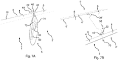
- Fig. 7A illustrates a perspective view of a construction system 5 according to one embodiment of the invention.
- Fig. 7B illustrates a close-up view of a portion of the construction system 5 shown in Fig. 7A .
- the construction system 5 comprises two adjacent construction elements 2, 2' each comprising a core structure comprising an insulation material 8 sandwiched between a first reinforcement structure 6 and a second reinforcement structure 6'.
- a first plate 4 is attached to the first reinforcement structure 6 and wherein a second plate 4' is attached to the second reinforcement structure 6'.
- the two adjacent construction elements 2, 2' are mechanically attached to each other by means of screws 60 provided in a region of overlap 74.
- the screws 60 may be covered by a cover member 70 configured to be attached to the top surface of the screw 60.
- the construction system 5 comprises two connection portions 38, 38', in which a protruding structure 22 in one of the construction elements 2, 2' is received by a corresponding receiving portion of the adjacent construction element 2, 2'.
- the protruding element 22 is provided next to a protruding element 40 that is received by a receiving portion.
- a small gap 42 is provided between the two adjacent construction elements 2, 2'.
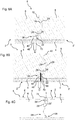
- Fig. 8A illustrates a cross-sectional view of a portion of a construction system 5 comprising two adjacent construction elements 2, 2' that are mechanically attached to each other by means of a nail 70.
- Fig. 8B illustrates a cross-sectional view of a portion of a construction system 5 that basically corresponds to the one shown in Fig. 8A and comprises two adjacent construction elements 2, 2' that are mechanically attached to each other by means of a screw 60.
- the construction systems 5 shown in Fig. 8A and in Fig. 8B comprise two adjacent construction elements 2, 2'.
- the first construction element 2 comprises a plane portion 28 arranged next to an arced portion 29.
- the second construction element 2' comprises a plane portion 28' arranged next to an arced portion 29'.
- a gap 42 is provided between the plane portions 28, 28' and the arced portions 29, 29'.
- the second construction element 2' comprises a protruding element 22 provided next to a protruding element 40 of the first construction element 2.
- the protruding element 40 is received by a receiving portion of the second construction element 2', wherein the protruding element 22 is received by a corresponding receiving element of the first construction element 2.
- the nail 70 penetrates a plate 4 of the first construction element 2, the protruding element 40 of the construction element 2, the protruding element 22 of the second construction element 2' and a portion (the insulation material 8) of the first construction element 2 arranged in a longer distance from the plate 4 than the protruding element 22 of the second construction element 2'.
- the screw 60 penetrates the plate 4 of the first construction element 2, the protruding element 40 of the construction element 2, the protruding element 22 of the second construction element 2' and a portion of the insulation material 8 of the first construction element 2 arranged in a longer distance from the plate 4 than the protruding element 22 of the second construction element 2'.
- Tape 72 has been attached to the plate 4 of the second construction element 2'. The tape 72 covers the screw 60.
- the screw 60 and nail 70 are inserted into the connection portion 38 in a distance D from the joint 46 of the constructions elements 2, 2'.
- Fig. 8C illustrates a construction system 5 according to one embodiment of the invention.
- the construction system 5 comprises two adjacent construction elements 2, 2' like the one shown in Fig. 8A and Fig. 8B . It can be seen that a screw 60 is being inserted into a region of overlap 74 of the construction system 5.
Landscapes
- Engineering & Computer Science (AREA)
- Architecture (AREA)
- Physics & Mathematics (AREA)
- Civil Engineering (AREA)
- Structural Engineering (AREA)
- Electromagnetism (AREA)
- Acoustics & Sound (AREA)
- Joining Of Building Structures In Genera (AREA)
Abstract
Description
- The present invention relates to a construction system suitable for being used in building constructions. The present invention more particularly relates to a construction system that is easy to mount and eliminates the risk of rot and moulds growth.
- It is known to apply insulation materials sandwiched between metal reinforcement plate structures. These modules are typically called sandwich panels and may comprise expanded foam such as polyurethane (PUR) or polyisocyanurate (PIR) sandwiched between steel plates. In order to achieve the mechanical properties (load-bearing capacity) required to use these panels in building constructions (e.g. domestic buildings), it is necessary to manually attach plates to the steel plates. This process is time consuming, difficult to accomplish within small tolerances and requires highly skilled personnel.
- Thus, there is a need for an improved construction system suitable for being used in building constructions. Accordingly, it is an object of the present invention to provide a construction system that reduces or even eliminates the above-mentioned disadvantages of the prior art. It is also an object of the present invention to provide a construction system, in which the adjacent construction elements are attached firmly to each other. It is furthermore an object to the invention to provide a fire-resistant construction system.
- The object of the present invention can be achieved by a construction system as defined in claim 1. Preferred embodiments are defined in the dependent sub claims, explained in the following description and illustrated in the accompanying drawings.
- The construction system according to the invention is a construction system comprising two adjacent construction elements, wherein each construction element comprises a core structure comprising an insulation material sandwiched between a first reinforcement structure and a second reinforcement structure, wherein a first plate is attached to the first reinforcement structure and wherein a second plate is attached to the second reinforcement structure, wherein the two adjacent construction elements are mechanically attached to each other by means of attachment members in a region of overlap.
- Hereby, it is possible to provide a construction element having the load-bearing capacity required for using the construction element in building constructions including domestic buildings. Furthermore, there is no need to manually attach any plates to the construction elements, since they are ready to be used without additional plates attached thereto. It is, however, possible to attach additional plates or structures (e.g. plasterboard) to the plates of the construction element if desired.
- Accordingly, the mounting procedure is eased and can be done much faster by using the construction system according to the invention than the prior art panels. Besides, the adjacent construction elements can be firmly attached to each other. Furthermore, it is possible to provide a fire-resistant construction system.
- Each construction element has a core structure comprising an insulation material sandwiched between a first reinforcement structure and a second reinforcement structure. The insulation material is preferably made of PUR or PIR.
- The first plate is attached to the outside surface of the first reinforcement structure and the second plate is attached to the outside surface of the second reinforcement structure may be any suitable type of plate that can provide the required load-bearing capacity of the construction element. It is, however, preferred that the first plate and/or the second plate is made in a fire-resistant material.
- By mechanically attaching the two adjacent construction elements to each other by means of attachment members in a region of overlap it is possible to provide a firm and reliable attachment of the adjacent construction elements.
- By the term "region of overlap" is meant a region, in which there is overlap between adjacent construction elements. An overlap may be provided in a protruding structure of one of the construction elements is received by a corresponding receiving structure of the other construction element.
- In one embodiment, the attachment members are screws or nails. It may be an advantage to apply attachment members, preferably screws or nails formed in a fire-resistant material or nails. Hereby, displacement of the adjacent construction elements due to high temperatures (e.g. during a fire) can be prevented. Accordingly, the invention provides a fire-resistant construction system.
- It may be an advantage that the attachment members are arranged in a configuration extending along a zone being parallel to a joint of the adjacent construction elements, wherein the zone is arranged in a non-zero distance from the from the joint. Hereby, it is possible to ensure that the attachment members are inserted in areas, in which they penetrate a first structure of a first construction element and a first structure of a second adjacent construction element so that a firm attachment of the adjacent construction elements.
- In one embodiment, said distance is in the range 3-50 mm. In one embodiment, said distance is in the range 5-30 mm, such as 6-20 mm. In one embodiment, the distance is approximately 10 mm.
- It may be beneficial that the attachment members extend along a line extending parallel to the joint. Hereby, the fixation of the adjacent construction elements can be eased. Furthermore, it can be ensured that the attachment members are inserted into the most optimum structures of the construction system.
- It may be advantageous that the attachment members penetrate a first structure of a first construction element, a first structure of a second adjacent construction element and a second structure of a first construction element. Hereby, a reliable and firm attachment of the adjacent structures can be achieved.
- It may be an advantage that the attachment members penetrate a first structure of a first construction element, a first structure of a second adjacent construction element, a second structure of a first construction element and a second structure of the second construction element. Hereby, an even more reliable and firm attachment of the adjacent structures can be achieved.
- It may be an advantage that the first plate and/or the second plate are attached to the reinforcement structures by means of glue. The glue may preferably be an inorganic glue. The glue preferably comprises a ductile adhesive. The glue preferably ensures a degree of adherence (quality of adhering) equal or greater than the degree of adherence of the insulation material. Hereby, it is possible to avoid a thermal bridge between a mechanical attachment member (e.g. a screw or a nail) and the core structure of the construction element. The use of glue makes it possible to achieve a large contact surface and to prevent pockets of air between the reinforcement structures and the plates attached thereto.
- It may be advantageous that the first plate and/or the second plate are attached to the reinforcement structures by means of mechanical attachment members. Hereby, the attachment process can be carried out in a fast manner. The mechanical attachment members may be screws, nails or corresponding mechanical structures provided in the reinforcement structures and the plates.
- It may be beneficial that the first plate and/or the plate is a cement board. Hereby, it is possible to provide a construction element that has the required load-bearing capacity and at the same time is fire-resistant.
- It may be an advantage that the insulation material comprises PUR or PIR. Hereby, it is possible to provide a construction element having a good insulation capacity and at the same time is relative stiff and does not take up a lot of space
- Preferably the insulation material is made in PUR or PIR. It may be advantageous that the core structure is made by moulding an insulation material made in PUR or PIR between the reinforcement structures.
- When the core structure has cured, it is possible to cut the core structure into construction elements having predefined dimensions. The plates may be attached to the core structure before or after the cutting process.
- It may be advantageous that the first reinforcement structure and/or the second reinforcement structure is made of metal. Hereby, it is possible to achieve a core structure that is resistant to impacts and is suitable of getting additional plates attached to the reinforcement structures. The reinforcement structures may preferably be made in steel. In one embodiment according to the invention the reinforcement structures are made in stainless steel.
- It may be beneficial that first reinforcement structure and/or the second reinforcement structure is shaped as corrugated plates. Hereby, it is possible to enhance the mechanical properties of the reinforcement plates. By applying corrugated plates, it is possible to enhance the bending stiffness and torsional rigidity of the plates.
- Preferably, the first reinforcement structure and/or the second reinforcement structure is made as a trapezoid plate.
- It may be beneficial that the construction element comprises a first end portion and a corresponding second end portion, wherein the first end portion comprises one or more protruding structures configured to be received by corresponding receiving structures provided in the second end portion.
- Hereby, it is possible to engagingly connect the adjacent end portions of construction elements according to the invention. Accordingly, it is possible to join adjacent construction elements in an easy manner.
- It may be an advantage that the construction element comprises a first end portion and a corresponding second end portion, wherein the second end portion comprises one or more male portions configured to be received by corresponding female portions provided in the first end portion. Hereby, it is possible to engagingly connect the adjacent end portions of construction elements according to the invention. Accordingly, it is possible to achieve an even stronger connection of adjacent construction elements.
- It may be advantageous that the construction element comprises a plane end portion. Hereby, it is possible to use the construction element to build a corner structure. E.g. a corner structure of a domestic building such as a family house.
- It may be beneficial that the construction element comprises a cutaway provided in the top portion of the construction element. Hereby, it is possible to supportingly arrange a wall plate in the cutaway. Thus, it is possibly to attach rafters of a roof construction to the wall plate.
- It may be beneficial that the cutaway portion is configured to receive a box-shaped elongated wall plate.
- The cutaway portion may have a box-shaped geometry having a longitudinal axis that extends parallel to the longitudinal axis X of the construction element.
- It may be an advantage that the construction element is constructed in such a manner that a gap is provided between the insulation material of adjacent construction elements when the construction elements bear against (abut) each other. Hereby the risk for damage during storing and transport can be reduced.
- The invention will become more fully understood from the detailed description given herein below. The accompanying drawings are given by way of illustration only, and thus, they are not limitative of the present invention. In the accompanying drawings:
- Fig. 1A
- shows a schematic, cross-sectional view of a construction element according to the invention in a non-assembled configuration, in which the inner plate and outer plate have not yet been attached to the sandwiched core structure;
- Fig. 1B
- shows a schematic, cross-sectional view of the construction element shown in
Fig. 1A in an assembled configuration; - Fig. 2A
- shows a schematic, perspective top view of a first construction element attached to a second construction element to form a corner portion;
- Fig. 2B
- shows a schematic, top view of two construction elements according to the invention attached to each other and hereby constitution a corner portion;
- Fig. 3A
- shows a schematic, perspective view of a first end portion of a construction element according to the invention;
- Fig. 3B
- shows a schematic, perspective of a reinforcement structure of a construction element according to the invention;
- Fig. 4A
- shows a schematic, perspective view of a top portion of a construction element according to the invention;
- Fig. 4B
- shows a schematic, perspective top view of two joint construction elements of a construction system according to the invention;
- Fig. 5A
- shows a schematic, perspective view of the connection portion of a connection system according to the invention;
- Fig. 5B
- shows a close-up view of a portion of the connection system shown in
Fig. 5A ; - Fig. 6A
- shows a schematic top view of a construction element according to the invention;
- Fig. 6B
- shows a schematic top view of a construction system according to the invention provided with additional plates;
- Fig. 7A
- shows a perspective view of construction system according to one embodiment of the invention;
- Fig. 7B
- shows a close-up view of a portion of the construction system shown in
Fig. 7A ; - Fig. 8A
- shows a cross-sectional view of a portion of a construction system according to one embodiment of the invention;
- Fig. 8B
- shows a cross-sectional view of a portion of a construction system that basically corresponds to the one shown in
Fig. 8A and - Fig. 8C
- shows a construction system according to one embodiment of the invention.
- Referring now in detail to the drawings for the purpose of illustrating preferred embodiments of the present invention, a
construction element 2 of the present invention is illustrated inFig. 1A . -
Fig. 1A illustrates a schematic, cross-sectional view of aconstruction element 2 of a connection system according to the invention, wherein theconstruction element 2 is in a non-assembled configuration. Theconstruction element 2 comprises acore structure 3 comprising aninsulation material 8 sandwiched between afirst reinforcement structure 6 and a second first reinforcement structure 6'. Thefirst reinforcement structure 6 is attached to the opposite side of theinsulation material 8 than the second reinforcement structure 6'. Theinsulation material 8 may be an expanded foam such as PUR or PIR. - As it can be seen in
Fig. 1A , theconstruction element 2 comprises acore structure 3, a first plate 4 (inner plate) and a second plate 4' (outer plate) that have not yet been attached to the sandwichedcore structure 3. - In
Fig. 1B , however, thefirst plate 4 and the second outer plate 4' that are attached to the sandwichedcore structure 3. Accordingly,Fig. 1B illustrates a schematic, cross-sectional view of theconstruction element 2 shown inFig. 1A in an assembled configuration. - The
first plate 4 and the second outer plate 4' are preferably made of a fire-resistant material. Such fire-resistant material may be a cement board comprising cement and reinforcing fibres. It is possible to replace one of theplates 4, 4' with a plate made in another material. However, in a preferred embodiment according to the invention theconstruction element 2 comprises acore structure 3, a first cement board plate 4 (inner plate) and a second cement board plate 4' (outer plate), wherein both thefirst plate 4 and the second plate 4' have been attached to the sandwichedcore structure 3. - It may be an advantage to glue the
first plate 4 and the second plate 4' to the sandwichedcore structure 3. The glue may preferably be a flexible and ductile glue. Alternatively, thefirst plate 4 and the second plate 4' can be attached to the sandwichedcore structure 3 by means of mechanical attachment elements. - The
first reinforcement structure 6 and the second reinforcement structure 6' are corrugated plates. In a preferred embodiment according to the invention thefirst reinforcement structure 6 and the second reinforcement structure 6' are steel plates. Preferablysteel trapezoid plates 6, 6'. By applyingcorrugated plates 6, 6' it is possible to enhance the bending stiffness and torsional rigidity of theplates 6, 6'. - As shown in
Fig. 1B , a plurality ofspaces 10, 10' are provided between thereinforcement structures 6, 6' and theplates 4, 4' attached thereto. - The
plates 4, 4' are attached to only the outwardly facing plane structures of thereinforcement structures 6, 6'. Accordingly, a portion of thereinforcement structures 6, 6' is not in contact with theplates 4, 4'. - The
core structure 3 can be manufactured by using a lamination process, e.g. a PUR laminating line in which PUR or PIR is injected into a space defined by two steel reinforcement structures. Afterwards, when the PUR or PIR has hardened, the product may be cut into predefined modules (core structures). Hereafter, theplates 4, 4' can be attached to the modules (core structures) and the construction element is ready to be used. It may be an advantage to provide end portions having specific (e.g. matching) geometries to make it easy and safe to transport, store and join the modules (core structures). - The
construction element 2 according to the invention may be used in building constructions. The use ofconstruction elements 2 according to the invention may reduce the construction time and ease the mounting process. Furthermore, since theconstruction elements 2 can be made in inorganic material, the risk of rot and moulds growth on building materials may be reduced or even eliminated. - The thickness T3 of the
insulation material 8 is larger than the thickness T2 of theplates 4, 4'. Furthermore, the thickness T2 of theplates 4, 4' is larger than the thickness T1 of thereinforcement structures 6, 6'. - In one embodiment according to the invention the thickness T3 of the
insulation material 8 is in the range 100-400 mm, preferably 150-300 mm such as approximately 200 mm, whereas the thickness T2 of theplates 4, 4' is approximately 5-30 mm, preferably 10-20 mm such as 6 mm. The thickness T1 of thereinforcement structures 6, 6' may be in the range 3-30 mm, preferably 5-10 mm such as 6 mm. -
Fig. 2A illustrates a schematic, perspective top view of afirst construction element 2 attached to a second construction element 2'. The construction forms acorner portion 12. Thefirst construction element 2 comprises aninsulation material 8 sandwiched between twometal reinforcement plates 6, 6' that preferably are made of corrugated steel. A boxed-shaped outercement board plate 4 is glued to the outside surface of thereinforcement plate 6, whereas another boxed-shaped outercement board plate 4 is glued to the outside surface of the other reinforcement plate 6'. - The
first construction element 2 comprises afirst end portion 16 shaped to engage with a corresponding end portion shaped as thesecond end portion 18 of the second construction element 2'. Thefirst construction element 2 comprises a secondplane end portion 20 provided in the opposite end than thefirst end portion 16. - The second construction element 2' comprises a
plane end portion 20 provided in the opposite end than thesecond end portion 18. Theplane end portion 20 abuts the plate 4' of thefirst construction element 2. - The second construction element 2' comprises an
insulation material 8 sandwiched between twometal reinforcement plates 6, 6', preferably corrugatedsteel reinforcement plates 6, 6'. A boxed-shaped outercement board plate 4 is glued to the outside surface of thereinforcement plate 6, whereas another boxed-shaped outercement board plate 4 is glued to the outside surface of the other reinforcement plate 6'. - The
first construction element 2 and the second construction element 2' are angled 90 degrees relative to each other. Abracket 14 like the one shown inFig. 2A may be attached to the inside plates 4' of thefirst construction element 2 and the second construction element 2' for improving the mechanical strength of thecorner portion 12. Thebracket 14 may be screwed or nailed into theconstruction elements 2, 2' or alternative attached by means of glue. -
Fig. 2B illustrates a schematic, top view of twoconstruction elements 2, 2' according to the invention attached to each other and hereby constitution acorner portion 12. - The
first construction element 2 comprises aninsulation material 8 sandwiched between twometal reinforcement plates 6, 6'. A boxed-shaped outercement board plate 4 is attached to the outside surface of thereinforcement plate 6, whereas another boxed-shaped outercement board plate 4 is glued to the outside surface of the other reinforcement plate 6'. - The
first construction element 2 comprises aplane end portion 20 abutting the inside portion of theouter plate 4 of the second construction element 2'. - The second construction element 2' comprises a
plane end portion 20 that abuts the plate 4' of thefirst construction element 2. - The second construction element 2' comprises an
insulation material 8 sandwiched between twosteel reinforcement plates 6, 6'. A boxed-shaped outercement board plate 4 is glued to the outside surface of thereinforcement plate 6, whereas another boxed-shaped outercement board plate 4 is glued to the outside surface of the other reinforcement plate 6'. -
Fig. 3A illustrates a schematic, perspective view of afirst end portion 16 of aconstruction element 2 according to the invention. It can be seen that theconstruction element 2 comprises aninsulation material 8 provided at the inside of asteel trapezoid plate 6. Thesteel trapezoid plate 6 is provided with an end section comprising a protruding structure having a conical shape (being thinnest at the distal end) and an L-shapedportion 24 extending in extension of the protrudingstructure 22. A receivingportion 32 is provided next to the protrudingstructure 22. - A
cement board 4 is attached to the protruding outside surfaces of thetrapezoid plate 6. The attachment may be carried out by using glue or mechanical attachment means (such as nails or screws). The end portion of thecement board 4 is aligned with the distal portion of the protrudingstructure 22. Acavity 30 is provided in theinsulation material 8 at theend portion 16. Aplane portion 28 is provide next to thecavity 30. Thecavity 30 is configured to receive a corresponding male portion 36 (seeFig. 5A ). -
Fig. 3B illustrates a schematic, perspective of a section of areinforcement structure 6 corresponding to the one shown inFig. 3A . Thereinforcement structure 6 comprises front portions 62 (that abut the outer plate shown inFig. 3A ) provided between rear portions 64 (that are not in contact with the outer plate shown inFig. 3A ) extending parallel to theportions 62.Connection structures 66, 66' connects adjacentfront portions 62 andrear portions 64. -
Fig. 4A illustrates a schematic, perspective view of a top portion of aconstruction element 2 according to the invention. Theconstruction element 2 comprises aninsulation material 8. Acutaway portion 58 is provided in the top portion of theinsulation material 8, preferably made an expanded foam such as PUR or PIR. Thecutaway portion 58 is configured to receive a wall plate (not shown) onto which the rafter of a roof construction can be attached. - The
cutaway portion 58 has a box-shaped geometry having a longitudinal axis that extends parallel to the longitudinal axis X of theconstruction element 2. Theconstruction element 2 has a transversal axis Y and a lateral axis Z. - The
construction element 2 comprises a core structure having aninsulation material 8 sandwiched between afirst reinforcement structure 6 and a second first reinforcement structure 6', wherein thefirst reinforcement structure 6 is attached to the opposite side of theinsulation material 8 than the second reinforcement structure 6'. Thereinforcement structures 6, 6' are preferably made of corrugated steel plates. - The
first plate 4 and the second plate 4' are preferably made of a fire-resistant material, preferably cement board. Theconstruction element 2 comprises afirst end portion 16 and asecond end portion 18. Thefirst end portion 16 is configured and shaped to engage with the correspondingsecond end portion 18 of thesecond construction element 2. -
Fig. 4B illustrates a schematic, perspective top view of aconstruction system 5 according to the invention. Theconstruction system 5 comprises twojoint construction elements 2, 2'. Each of the twojoint construction elements 2, 2' basically corresponds to the one shown inFig. 4A , however, nocutaway portion 58 is provided in theconstruction elements 2, 2'. - The
first construction element 2 comprises a first end portion and asecond end portion 18, whereas the second construction element 2' comprises afirst end portion 16 and a second end portion. The first end portion of thefirst construction element 2 abuts the second end portion of the second construction element 2'. Thefirst construction element 2 and the second construction element 2' are joint in ajoint portion 36 comprising a joint 46 extending along the transversal axis Y of theconstruction elements 2, 2'. The longitudinal axis X and the lateral axis Z of theconstruction elements 2, 2' are shown. - It can be seen that both
construction elements 2, 2' comprise aninsulation material 8 sandwiched between two corrugatedsteel reinforcement plates 6, 6' andplates 4, 4' attached to the outside surface of thereinforcement plates 6, 6'. Theconstruction elements 2, 2' are joint in ajoint portion 34 that comprises a joint 46 extending along the transversal axis Y of the construction element 2'. -
Fig. 5A illustrates a schematic, perspective view of thejoint portion 34 comprising aconnection portion 38 of aconstruction system 5 comprising twoadjacent construction elements 2, 2'. Eachconstruction element 2, 2' comprises aninsulation material 8 sandwiched between tworeinforcement plates 6, 6'. Plates made ofcement boards 4, 4' are attached to the outside of thereinforcement plates 6, 6'. - The
joint portion 34 comprises a joint 46 extending along the transversal axis (extending perpendicular to the longitudinal axis X and the lateral axis Z) of the of the construction element 2'. The adjacent end portion of theconstruction elements 2, 2' constitute thejoint portion 34. - The end portion of the
first construction element 2 is provided withfemale structures 30 shaped as arced cavities. The adjacent end portion of the second construction element 2' comprises correspondingmale portions 36 shaped as arced protruding elements. - The end portion of the
first construction element 2 comprisesplane portions 28 corresponding to matching plane portions 28' of the adjacent end portion of the second construction element 2'. Aportion connection portion 38 is surrounded by a dotted ellipse. A close-up view of this portion is shown inFig. 5B . - It can be seen that a part of the
connection portion 38 is made by a protrudingportion 22 having a conical geometry. The protrudingportion 22 is made as an extension of asteel trapezoid plate 6 of thefirst construction element 2. The protrudingstructure 22 has its smallest thickness at its distal end. An L-shapedportion 24 extends in extension of the protrudingstructure 22. A receiving portion is provided next to the protrudingstructure 22 and a protrudingelement 40 of the second construction element 2' has been received by the receiving portion. Accordingly, asmall gap 42 is provided between the twoadjacent construction elements 2, 2'. The gap may be approximately 2-60 mm, preferably 3-40 mm, such as 5-30 mm. - The second construction element 2' is provided with a receiving
structure 48 configured to receive the protrudingstructure 22 of thefirst construction element 2. The end portion of thefirst construction element 2 comprisesplane portions 28 corresponding to matching plane portions 28' of the adjacent end portion of the second construction element 2'. - While the
plates 4 of theconstruction elements 2, 2' abut each other, the geometry of the adjacent end portions prevents the end portions ofadjacent construction elements 2, 2' to get into physical contact with each other. Accordingly, the construction detail protects the end portions from being damaged due to contact with the corresponding end portion. -
Attachment members 44 are used to fix the two adjacent construction elements to each other. Theattachment members 44 may be screws, nails or other mechanical means suitable for fixing the adjacent end portions of theconstruction elements 2, 2' to each other. Theattachment members 44 are arranged in a configuration extending along aline 56 parallel to the joint 46. Theline 56 is, however, displaced a distance D from the joint 46. -
Fig. 6A illustrates a schematic top view of aconstruction element 2 according to the invention. Theconstruction element 2 comprises aninsulation material 8 sandwiched between afirst reinforcement structure 6 and a second reinforcement structure 6'. Afirst plate 4 is glued to the outside surface of thefirst reinforcement structure 6, whereas a second plate 4' is glued to the outside surface of the second reinforcement structure 6'. Theconstruction element 2 comprises afirst end portion 16 provided with twocavities 30, receivingportions 32 and protrudingstructures 22. Theconstruction element 2 comprises asecond end portion 18 provided with twomale portions 36, receivingstructures 48 and protruding structures 22'. -
Fig. 6B illustrates a schematic top view of aconstruction system 5 comprising twojoint construction elements 2, 2' provided withadditional plates construction element 2, 2' corresponds to the one shown inFig. 6A . The twoconstruction elements 2, 2' have been joint and thejoint portion 34 shows that the abutting end portions of theadjacent construction elements 2, 2' have engaging geometries. - The
joints 46 of theplates 4, 4' are arranged in a distance from thejoints 54, 54' of theplates plates plates 4, 4' by any suitable attachment means, such as mechanical attachment members (e.g. screws or nails) or glue. Theplates -
Fig. 7A illustrates a perspective view of aconstruction system 5 according to one embodiment of the invention.Fig. 7B illustrates a close-up view of a portion of theconstruction system 5 shown inFig. 7A . Theconstruction system 5 comprises twoadjacent construction elements 2, 2' each comprising a core structure comprising aninsulation material 8 sandwiched between afirst reinforcement structure 6 and a second reinforcement structure 6'. Afirst plate 4 is attached to thefirst reinforcement structure 6 and wherein a second plate 4' is attached to the second reinforcement structure 6'. - The two
adjacent construction elements 2, 2' are mechanically attached to each other by means ofscrews 60 provided in a region ofoverlap 74. Thescrews 60 may be covered by acover member 70 configured to be attached to the top surface of thescrew 60. Theconstruction system 5 comprises twoconnection portions structure 22 in one of theconstruction elements 2, 2' is received by a corresponding receiving portion of theadjacent construction element 2, 2'. The protrudingelement 22 is provided next to a protrudingelement 40 that is received by a receiving portion. Asmall gap 42 is provided between the twoadjacent construction elements 2, 2'. -
Fig. 8A illustrates a cross-sectional view of a portion of aconstruction system 5 comprising twoadjacent construction elements 2, 2' that are mechanically attached to each other by means of anail 70.Fig. 8B illustrates a cross-sectional view of a portion of aconstruction system 5 that basically corresponds to the one shown inFig. 8A and comprises twoadjacent construction elements 2, 2' that are mechanically attached to each other by means of ascrew 60. - The
construction systems 5 shown inFig. 8A and inFig. 8B comprise twoadjacent construction elements 2, 2'. Thefirst construction element 2 comprises aplane portion 28 arranged next to an arcedportion 29. Likewise, the second construction element 2' comprises a plane portion 28' arranged next to an arced portion 29'. Agap 42 is provided between theplane portions 28, 28' and the arcedportions 29, 29'. - The second construction element 2' comprises a protruding
element 22 provided next to a protrudingelement 40 of thefirst construction element 2. The protrudingelement 40 is received by a receiving portion of the second construction element 2', wherein the protrudingelement 22 is received by a corresponding receiving element of thefirst construction element 2. - In
Fig. 8A , thenail 70 penetrates aplate 4 of thefirst construction element 2, the protrudingelement 40 of theconstruction element 2, the protrudingelement 22 of the second construction element 2' and a portion (the insulation material 8) of thefirst construction element 2 arranged in a longer distance from theplate 4 than the protrudingelement 22 of the second construction element 2'. InFig. 8B , thescrew 60 penetrates theplate 4 of thefirst construction element 2, the protrudingelement 40 of theconstruction element 2, the protrudingelement 22 of the second construction element 2' and a portion of theinsulation material 8 of thefirst construction element 2 arranged in a longer distance from theplate 4 than the protrudingelement 22 of the second construction element 2'.Tape 72 has been attached to theplate 4 of the second construction element 2'. Thetape 72 covers thescrew 60. Thescrew 60 andnail 70 are inserted into theconnection portion 38 in a distance D from the joint 46 of theconstructions elements 2, 2'. -
Fig. 8C illustrates aconstruction system 5 according to one embodiment of the invention. Theconstruction system 5 comprises twoadjacent construction elements 2, 2' like the one shown inFig. 8A and Fig. 8B . It can be seen that ascrew 60 is being inserted into a region ofoverlap 74 of theconstruction system 5. -
- 2, 2'
- Construction element
- 3
- Core structure
- 4, 4'
- Plate
- 5
- Construction system
- 6, 6'
- Reinforcement structure
- 8
- Insulation material
- 10, 10'
- Space
- 12
- Corner portion
- 14
- Bracket
- 16
- First end portion
- 18
- Second end portion
- 20
- Plane end portion
- 22, 22'
- Protruding structure
- 24
- L-shaped portion
- 26
- Edge portion
- 28, 28'
- Plane portion
- 29, 29'
- Arced portion
- 30
- Cavity
- 32
- Receiving portion
- 34
- Joint portion
- 36
- Male portion
- 38, 38'
- Connection portion
- 40
- Protruding element
- 42
- Gap
- 44
- Attachment member
- 46
- Joint
- 48
- Receiving structure
- 50, 50', 52, 52'
- Plate
- 54, 54'
- Joint
- 56
- Line
- 58
- Cutaway portion
- 60
- Screw
- 62
- Front portion
- 64
- Rear portion
- 66, 66'
- Connection portion
- 68
- Nail
- 70
- Cover member
- 72
- Tape
- 74
- Region of overlap
- T1, T2, T3
- Thickness
- X
- Longitudinal axis
- Y
- Transversal axis
- Z
- Lateral axis
- D
- Distance
- L
- Distance
Claims (15)
- A construction system (5) comprising two adjacent construction elements (2, 2'), wherein each construction element (2, 2') comprises a core structure (3) comprising an insulation material (8) sandwiched between a first reinforcement structure (6) and a second reinforcement structure (6'), wherein a first plate (4) is attached to the first reinforcement structure (6) and wherein a second plate (4') is attached to the second reinforcement structure (6'), characterised in that the two adjacent construction elements (2, 2') are mechanically attached to each other by means of attachment members (44, 60, 68) in a region of overlap (74).
- A construction system (5) according to claim 1, characterised in that the attachment members (44, 60, 68) are arranged in a configuration extending along a zone being parallel to a joint (46) of the adjacent construction elements (2, 2'), wherein the zone is arranged in a non-zero distance (D) from the from the joint (46), wherein said distance (D) is in the range 3-50 mm.
- A construction system (5) according to claim 1 or 2, characterised in that the attachment members (44, 60, 68) extend along a line (56) extending parallel to the joint (46).
- A construction system (5) according to one of the preceding claims, characterised in that the attachment members (44, 60, 68) penetrate:- a first structure (4) of a first construction element (2);- a first structure (42) of a second adjacent construction element (2') and- a second structure (22) of a first construction element (2);
- A construction system (5) according to claim 4, characterised in that the attachment members (44, 60, 68) penetrate a second structure (41) of the second construction element (2');
- A construction system (5) according to one of the preceding claims, characterised in that the first plate (4) and/or the second plate (4') are attached to the reinforcement structures (6, 6') by means of glue.
- A construction system (5) according to one of the preceding claims, characterised in that the first plate (4) and/or the second plate (4') are attached to the reinforcement structures (6, 6') by means of mechanical attachment members.
- A construction system (5) according to one of the preceding claims, characterised in that the first plate (4) and/or the second plate (4') is a cement board (4, 4').
- A construction element (2, 2') according to one of the preceding claims, characterised in that the insulation material (8) comprises PUR or PIR.
- A construction system (5) according to one of the preceding claims, characterised in that the first reinforcement structure (6) and/or the second reinforcement structure (6') is made of metal.
- A construction system (5) according to claim 10, characterised in that first reinforcement structure (6) and/or the second reinforcement structure (6') is shaped as a corrugated plate.
- A construction system (5) according to one of the preceding claims, characterised in that the construction element (2, 2') comprises a first end portion (16) and a corresponding second end portion (18), wherein the first end portion (16) comprises one or more protruding structures (22) configured to be received by corresponding receiving structures (48) provided in the second end portion (18).
- A construction system (5) according to one of the preceding claims, characterised in that the construction element (2, 2') comprises a first end portion (16) and a corresponding second end portion (18), wherein the second end portion (18) comprises one or more male portions (36, 22') configured to be received by corresponding female portions (30, 48) provided in the first end portion (16).
- A construction system (5) according to one of the preceding claims, characterised in that the construction element (2, 2') comprises a plane end portion (20).
- A construction system (5) according to one of the preceding claims, characterised in that the construction element (2, 2') comprises a cutaway (58) provided in the top portion of the construction element (2, 2').
Applications Claiming Priority (1)
| Application Number | Priority Date | Filing Date | Title |
|---|---|---|---|
| DKPA201700314 | 2017-05-24 |
Publications (3)
| Publication Number | Publication Date |
|---|---|
| EP3406815A1 true EP3406815A1 (en) | 2018-11-28 |
| EP3406815C0 EP3406815C0 (en) | 2023-08-16 |
| EP3406815B1 EP3406815B1 (en) | 2023-08-16 |
Family
ID=62167124
Family Applications (1)
| Application Number | Title | Priority Date | Filing Date |
|---|---|---|---|
| EP18171281.1A Active EP3406815B1 (en) | 2017-05-24 | 2018-05-08 | Construction system |
Country Status (1)
| Country | Link |
|---|---|
| EP (1) | EP3406815B1 (en) |
Cited By (2)
| Publication number | Priority date | Publication date | Assignee | Title |
|---|---|---|---|---|
| WO2020115657A1 (en) * | 2018-12-04 | 2020-06-11 | Arcelormittal | Sandwich panel assembly and associated building |
| CN115419211A (en) * | 2022-09-07 | 2022-12-02 | 河北金石建筑设计有限公司 | A waterproof thermal-insulated type wallboard for housing construction design |
Citations (3)
| Publication number | Priority date | Publication date | Assignee | Title |
|---|---|---|---|---|
| FR2678304A1 (en) * | 1991-06-26 | 1992-12-31 | Fourgeaud Monique | Insulating panel and method for manufacturing it |
| WO1998050646A1 (en) * | 1997-05-08 | 1998-11-12 | Nabil Nasri Gazal | Modular sandwich panel and method for housing construction |
| US20090100780A1 (en) * | 2007-10-19 | 2009-04-23 | Mathis John P | Structural insulated panel system |
Family Cites Families (3)
| Publication number | Priority date | Publication date | Assignee | Title |
|---|---|---|---|---|
| US6418686B1 (en) * | 1997-04-25 | 2002-07-16 | Leading Edge Earth Products, Inc. | Insulated asymmetrical directional force resistant building panel with symmetrical joinery, integral shear resistance connector and thermal break |
| US7748181B1 (en) * | 2006-01-20 | 2010-07-06 | Centria | Advanced building envelope delivery system and method |
| MY147002A (en) * | 2008-12-19 | 2012-10-15 | Wong Chiang Heng | Nail-plated composite structural system |
-
2018
- 2018-05-08 EP EP18171281.1A patent/EP3406815B1/en active Active
Patent Citations (3)
| Publication number | Priority date | Publication date | Assignee | Title |
|---|---|---|---|---|
| FR2678304A1 (en) * | 1991-06-26 | 1992-12-31 | Fourgeaud Monique | Insulating panel and method for manufacturing it |
| WO1998050646A1 (en) * | 1997-05-08 | 1998-11-12 | Nabil Nasri Gazal | Modular sandwich panel and method for housing construction |
| US20090100780A1 (en) * | 2007-10-19 | 2009-04-23 | Mathis John P | Structural insulated panel system |
Cited By (4)
| Publication number | Priority date | Publication date | Assignee | Title |
|---|---|---|---|---|
| WO2020115657A1 (en) * | 2018-12-04 | 2020-06-11 | Arcelormittal | Sandwich panel assembly and associated building |
| WO2020115525A1 (en) * | 2018-12-04 | 2020-06-11 | Arcelormittal | Sandwich panel assembly |
| CN115419211A (en) * | 2022-09-07 | 2022-12-02 | 河北金石建筑设计有限公司 | A waterproof thermal-insulated type wallboard for housing construction design |
| CN115419211B (en) * | 2022-09-07 | 2023-12-26 | 河北金石建筑设计有限公司 | Waterproof heat-insulating wallboard for house building design |
Also Published As
| Publication number | Publication date |
|---|---|
| EP3406815C0 (en) | 2023-08-16 |
| EP3406815B1 (en) | 2023-08-16 |
Similar Documents
| Publication | Publication Date | Title |
|---|---|---|
| US6308491B1 (en) | Structural insulated panel | |
| US6205729B1 (en) | Asymmetric structural insulated panel | |
| US6481172B1 (en) | Structural wall panels | |
| US7805903B2 (en) | Locking mechanism for flooring boards | |
| US6408594B1 (en) | Reinforced structural insulated panels with plastic impregnated paper facings | |
| US9523197B2 (en) | Sound dampening wall | |
| US6698157B1 (en) | Structural insulated panel building system | |
| US6523324B1 (en) | Building panels with plastic impregnated paper | |
| EP2898157B1 (en) | Building board and method of mounting | |
| US8448401B2 (en) | Fiber cement board surface product | |
| US20090293419A1 (en) | Composite Building Panel | |
| RU2656260C2 (en) | Method for constructing building having strong thermal insulation and building constructed by means of said method | |
| US20030033774A1 (en) | Building panels with plastic impregnated paper | |
| US9909303B2 (en) | Building exterior insulation structure | |
| US11598089B2 (en) | Partition wall | |
| US8863463B2 (en) | Insulation building system for a building structure | |
| JP7504111B2 (en) | Building studs, wall structures comprising such building studs, and methods for forming wall structures | |
| US8959856B2 (en) | Building assembly with a corner profile for an insulating building system | |
| EP3406815B1 (en) | Construction system | |
| US11746519B2 (en) | Building construction system | |
| US6178708B1 (en) | Metal-faced angled spline for use with structural insulated panels | |
| EP2530212B1 (en) | Method and apparatus for joining structural insulated panels | |
| US6244016B1 (en) | Prefabricated wall panel | |
| US20250101734A1 (en) | Framing brackets and systems for shipping container interior | |
| JP2832240B2 (en) | Thermal insulation panel for wall, thermal insulation wall using the same, and method of construction |
Legal Events
| Date | Code | Title | Description |
|---|---|---|---|
| PUAI | Public reference made under article 153(3) epc to a published international application that has entered the european phase |
Free format text: ORIGINAL CODE: 0009012 |
|
| STAA | Information on the status of an ep patent application or granted ep patent |
Free format text: STATUS: THE APPLICATION HAS BEEN PUBLISHED |
|
| AK | Designated contracting states |
Kind code of ref document: A1 Designated state(s): AL AT BE BG CH CY CZ DE DK EE ES FI FR GB GR HR HU IE IS IT LI LT LU LV MC MK MT NL NO PL PT RO RS SE SI SK SM TR |
|
| AX | Request for extension of the european patent |
Extension state: BA ME |
|
| STAA | Information on the status of an ep patent application or granted ep patent |
Free format text: STATUS: REQUEST FOR EXAMINATION WAS MADE |
|
| 17P | Request for examination filed |
Effective date: 20190523 |
|
| RBV | Designated contracting states (corrected) |
Designated state(s): AL AT BE BG CH CY CZ DE DK EE ES FI FR GB GR HR HU IE IS IT LI LT LU LV MC MK MT NL NO PL PT RO RS SE SI SK SM TR |
|
| STAA | Information on the status of an ep patent application or granted ep patent |
Free format text: STATUS: EXAMINATION IS IN PROGRESS |
|
| 17Q | First examination report despatched |
Effective date: 20190724 |
|
| RAP1 | Party data changed (applicant data changed or rights of an application transferred) |
Owner name: CANTONA SYSTEM A/S |
|
| GRAP | Despatch of communication of intention to grant a patent |
Free format text: ORIGINAL CODE: EPIDOSNIGR1 |
|
| STAA | Information on the status of an ep patent application or granted ep patent |
Free format text: STATUS: GRANT OF PATENT IS INTENDED |
|
| INTG | Intention to grant announced |
Effective date: 20230314 |
|
| GRAS | Grant fee paid |
Free format text: ORIGINAL CODE: EPIDOSNIGR3 |
|
| GRAA | (expected) grant |
Free format text: ORIGINAL CODE: 0009210 |
|
| STAA | Information on the status of an ep patent application or granted ep patent |
Free format text: STATUS: THE PATENT HAS BEEN GRANTED |
|
| AK | Designated contracting states |
Kind code of ref document: B1 Designated state(s): AL AT BE BG CH CY CZ DE DK EE ES FI FR GB GR HR HU IE IS IT LI LT LU LV MC MK MT NL NO PL PT RO RS SE SI SK SM TR |
|
| RAP3 | Party data changed (applicant data changed or rights of an application transferred) |
Owner name: CANTONA SYSTEM A/S |
|
| REG | Reference to a national code |
Ref country code: CH Ref legal event code: EP |
|
| REG | Reference to a national code |
Ref country code: DE Ref legal event code: R096 Ref document number: 602018055349 Country of ref document: DE |
|
| REG | Reference to a national code |
Ref country code: IE Ref legal event code: FG4D |
|
| U01 | Request for unitary effect filed |
Effective date: 20230905 |
|
| U07 | Unitary effect registered |
Designated state(s): AT BE BG DE DK EE FI FR IT LT LU LV MT NL PT SE SI Effective date: 20230912 |
|
| PG25 | Lapsed in a contracting state [announced via postgrant information from national office to epo] |
Ref country code: GR Free format text: LAPSE BECAUSE OF FAILURE TO SUBMIT A TRANSLATION OF THE DESCRIPTION OR TO PAY THE FEE WITHIN THE PRESCRIBED TIME-LIMIT Effective date: 20231117 |
|
| PG25 | Lapsed in a contracting state [announced via postgrant information from national office to epo] |
Ref country code: IS Free format text: LAPSE BECAUSE OF FAILURE TO SUBMIT A TRANSLATION OF THE DESCRIPTION OR TO PAY THE FEE WITHIN THE PRESCRIBED TIME-LIMIT Effective date: 20231216 |
|
| PG25 | Lapsed in a contracting state [announced via postgrant information from national office to epo] |
Ref country code: RS Free format text: LAPSE BECAUSE OF FAILURE TO SUBMIT A TRANSLATION OF THE DESCRIPTION OR TO PAY THE FEE WITHIN THE PRESCRIBED TIME-LIMIT Effective date: 20230816 Ref country code: NO Free format text: LAPSE BECAUSE OF FAILURE TO SUBMIT A TRANSLATION OF THE DESCRIPTION OR TO PAY THE FEE WITHIN THE PRESCRIBED TIME-LIMIT Effective date: 20231116 Ref country code: IS Free format text: LAPSE BECAUSE OF FAILURE TO SUBMIT A TRANSLATION OF THE DESCRIPTION OR TO PAY THE FEE WITHIN THE PRESCRIBED TIME-LIMIT Effective date: 20231216 Ref country code: HR Free format text: LAPSE BECAUSE OF FAILURE TO SUBMIT A TRANSLATION OF THE DESCRIPTION OR TO PAY THE FEE WITHIN THE PRESCRIBED TIME-LIMIT Effective date: 20230816 Ref country code: GR Free format text: LAPSE BECAUSE OF FAILURE TO SUBMIT A TRANSLATION OF THE DESCRIPTION OR TO PAY THE FEE WITHIN THE PRESCRIBED TIME-LIMIT Effective date: 20231117 |
|
| PG25 | Lapsed in a contracting state [announced via postgrant information from national office to epo] |
Ref country code: PL Free format text: LAPSE BECAUSE OF FAILURE TO SUBMIT A TRANSLATION OF THE DESCRIPTION OR TO PAY THE FEE WITHIN THE PRESCRIBED TIME-LIMIT Effective date: 20230816 |
|
| PG25 | Lapsed in a contracting state [announced via postgrant information from national office to epo] |
Ref country code: ES Free format text: LAPSE BECAUSE OF FAILURE TO SUBMIT A TRANSLATION OF THE DESCRIPTION OR TO PAY THE FEE WITHIN THE PRESCRIBED TIME-LIMIT Effective date: 20230816 |
|
| PG25 | Lapsed in a contracting state [announced via postgrant information from national office to epo] |
Ref country code: SM Free format text: LAPSE BECAUSE OF FAILURE TO SUBMIT A TRANSLATION OF THE DESCRIPTION OR TO PAY THE FEE WITHIN THE PRESCRIBED TIME-LIMIT Effective date: 20230816 Ref country code: RO Free format text: LAPSE BECAUSE OF FAILURE TO SUBMIT A TRANSLATION OF THE DESCRIPTION OR TO PAY THE FEE WITHIN THE PRESCRIBED TIME-LIMIT Effective date: 20230816 Ref country code: ES Free format text: LAPSE BECAUSE OF FAILURE TO SUBMIT A TRANSLATION OF THE DESCRIPTION OR TO PAY THE FEE WITHIN THE PRESCRIBED TIME-LIMIT Effective date: 20230816 Ref country code: CZ Free format text: LAPSE BECAUSE OF FAILURE TO SUBMIT A TRANSLATION OF THE DESCRIPTION OR TO PAY THE FEE WITHIN THE PRESCRIBED TIME-LIMIT Effective date: 20230816 Ref country code: SK Free format text: LAPSE BECAUSE OF FAILURE TO SUBMIT A TRANSLATION OF THE DESCRIPTION OR TO PAY THE FEE WITHIN THE PRESCRIBED TIME-LIMIT Effective date: 20230816 |
|
| REG | Reference to a national code |
Ref country code: DE Ref legal event code: R097 Ref document number: 602018055349 Country of ref document: DE |
|
| PLBE | No opposition filed within time limit |
Free format text: ORIGINAL CODE: 0009261 |
|
| STAA | Information on the status of an ep patent application or granted ep patent |
Free format text: STATUS: NO OPPOSITION FILED WITHIN TIME LIMIT |
|
| U20 | Renewal fee for the european patent with unitary effect paid |
Year of fee payment: 7 Effective date: 20240528 |
|
| 26N | No opposition filed |
Effective date: 20240517 |
|
| U1N | Appointed representative for the unitary patent procedure changed after the registration of the unitary effect |
Representative=s name: ANDREASEN, SOEREN LAURSEN VASEGAARD; DK |
|
| REG | Reference to a national code |
Ref country code: CH Ref legal event code: PL |
|
| PG25 | Lapsed in a contracting state [announced via postgrant information from national office to epo] |
Ref country code: MC Free format text: LAPSE BECAUSE OF FAILURE TO SUBMIT A TRANSLATION OF THE DESCRIPTION OR TO PAY THE FEE WITHIN THE PRESCRIBED TIME-LIMIT Effective date: 20230816 |
|
| GBPC | Gb: european patent ceased through non-payment of renewal fee |
Effective date: 20240508 |
|
| PG25 | Lapsed in a contracting state [announced via postgrant information from national office to epo] |
Ref country code: MC Free format text: LAPSE BECAUSE OF FAILURE TO SUBMIT A TRANSLATION OF THE DESCRIPTION OR TO PAY THE FEE WITHIN THE PRESCRIBED TIME-LIMIT Effective date: 20230816 Ref country code: CH Free format text: LAPSE BECAUSE OF NON-PAYMENT OF DUE FEES Effective date: 20240531 |
|
| PG25 | Lapsed in a contracting state [announced via postgrant information from national office to epo] |
Ref country code: IE Free format text: LAPSE BECAUSE OF NON-PAYMENT OF DUE FEES Effective date: 20240508 |
|
| PG25 | Lapsed in a contracting state [announced via postgrant information from national office to epo] |
Ref country code: GB Free format text: LAPSE BECAUSE OF NON-PAYMENT OF DUE FEES Effective date: 20240508 |
|
| U20 | Renewal fee for the european patent with unitary effect paid |
Year of fee payment: 8 Effective date: 20250527 |
|
| PG25 | Lapsed in a contracting state [announced via postgrant information from national office to epo] |
Ref country code: CY Free format text: LAPSE BECAUSE OF FAILURE TO SUBMIT A TRANSLATION OF THE DESCRIPTION OR TO PAY THE FEE WITHIN THE PRESCRIBED TIME-LIMIT; INVALID AB INITIO Effective date: 20180508 |
|
| PG25 | Lapsed in a contracting state [announced via postgrant information from national office to epo] |
Ref country code: HU Free format text: LAPSE BECAUSE OF FAILURE TO SUBMIT A TRANSLATION OF THE DESCRIPTION OR TO PAY THE FEE WITHIN THE PRESCRIBED TIME-LIMIT; INVALID AB INITIO Effective date: 20180508 |
|
| PG25 | Lapsed in a contracting state [announced via postgrant information from national office to epo] |
Ref country code: TR Free format text: LAPSE BECAUSE OF FAILURE TO SUBMIT A TRANSLATION OF THE DESCRIPTION OR TO PAY THE FEE WITHIN THE PRESCRIBED TIME-LIMIT Effective date: 20230816 |
|
| U20 | Renewal fee for the european patent with unitary effect paid |
Year of fee payment: 9 Effective date: 20260527 |