EP3406700A1 - Cell culture substrate and method for producing same - Google Patents
Cell culture substrate and method for producing same Download PDFInfo
- Publication number
- EP3406700A1 EP3406700A1 EP17741466.1A EP17741466A EP3406700A1 EP 3406700 A1 EP3406700 A1 EP 3406700A1 EP 17741466 A EP17741466 A EP 17741466A EP 3406700 A1 EP3406700 A1 EP 3406700A1
- Authority
- EP
- European Patent Office
- Prior art keywords
- adhesive portion
- adhesive
- resin layer
- cell culture
- concave
- Prior art date
- Legal status (The legal status is an assumption and is not a legal conclusion. Google has not performed a legal analysis and makes no representation as to the accuracy of the status listed.)
- Withdrawn
Links
- 239000000758 substrate Substances 0.000 title claims abstract description 41
- 238000004113 cell culture Methods 0.000 title claims abstract description 40
- 238000004519 manufacturing process Methods 0.000 title claims description 11
- 239000000853 adhesive Substances 0.000 claims abstract description 187
- 230000001070 adhesive effect Effects 0.000 claims abstract description 178
- XLYOFNOQVPJJNP-UHFFFAOYSA-N water Substances O XLYOFNOQVPJJNP-UHFFFAOYSA-N 0.000 claims abstract description 12
- 239000000463 material Substances 0.000 claims abstract description 11
- 239000011342 resin composition Substances 0.000 claims description 42
- 238000005192 partition Methods 0.000 claims description 31
- 238000000034 method Methods 0.000 claims description 7
- 230000001678 irradiating effect Effects 0.000 claims description 2
- 230000035899 viability Effects 0.000 abstract description 4
- 239000002131 composite material Substances 0.000 abstract description 2
- 229920005989 resin Polymers 0.000 description 101
- 239000011347 resin Substances 0.000 description 101
- 210000004027 cell Anatomy 0.000 description 28
- 238000012546 transfer Methods 0.000 description 24
- 229910052731 fluorine Inorganic materials 0.000 description 17
- 239000000805 composite resin Substances 0.000 description 11
- 230000036267 drug metabolism Effects 0.000 description 11
- 239000000178 monomer Substances 0.000 description 10
- 125000001153 fluoro group Chemical group F* 0.000 description 9
- 229920000139 polyethylene terephthalate Polymers 0.000 description 9
- 239000005020 polyethylene terephthalate Substances 0.000 description 9
- YCKRFDGAMUMZLT-UHFFFAOYSA-N Fluorine atom Chemical compound [F] YCKRFDGAMUMZLT-UHFFFAOYSA-N 0.000 description 8
- 239000011737 fluorine Substances 0.000 description 8
- -1 polyethylene terephthalate Polymers 0.000 description 7
- 230000000052 comparative effect Effects 0.000 description 6
- 239000002609 medium Substances 0.000 description 6
- VYPSYNLAJGMNEJ-UHFFFAOYSA-N silicon dioxide Inorganic materials O=[Si]=O VYPSYNLAJGMNEJ-UHFFFAOYSA-N 0.000 description 6
- 239000002061 nanopillar Substances 0.000 description 5
- 235000012239 silicon dioxide Nutrition 0.000 description 5
- 239000006087 Silane Coupling Agent Substances 0.000 description 4
- PPBRXRYQALVLMV-UHFFFAOYSA-N Styrene Chemical compound C=CC1=CC=CC=C1 PPBRXRYQALVLMV-UHFFFAOYSA-N 0.000 description 4
- 230000015572 biosynthetic process Effects 0.000 description 4
- 238000011156 evaluation Methods 0.000 description 4
- 229920000098 polyolefin Polymers 0.000 description 4
- 238000002360 preparation method Methods 0.000 description 4
- 239000000047 product Substances 0.000 description 4
- 239000010453 quartz Substances 0.000 description 4
- 239000000126 substance Substances 0.000 description 4
- 238000009281 ultraviolet germicidal irradiation Methods 0.000 description 4
- KFZMGEQAYNKOFK-UHFFFAOYSA-N Isopropanol Chemical compound CC(C)O KFZMGEQAYNKOFK-UHFFFAOYSA-N 0.000 description 3
- 238000003475 lamination Methods 0.000 description 3
- 229920001296 polysiloxane Polymers 0.000 description 3
- 238000012545 processing Methods 0.000 description 3
- 239000012780 transparent material Substances 0.000 description 3
- 229940042596 viscoat Drugs 0.000 description 3
- 239000004925 Acrylic resin Substances 0.000 description 2
- 229920000178 Acrylic resin Polymers 0.000 description 2
- LFQSCWFLJHTTHZ-UHFFFAOYSA-N Ethanol Chemical compound CCO LFQSCWFLJHTTHZ-UHFFFAOYSA-N 0.000 description 2
- 101100494367 Mus musculus C1galt1 gene Proteins 0.000 description 2
- 101150035415 PLT1 gene Proteins 0.000 description 2
- 239000004695 Polyether sulfone Substances 0.000 description 2
- 239000004642 Polyimide Substances 0.000 description 2
- QVGXLLKOCUKJST-UHFFFAOYSA-N atomic oxygen Chemical compound [O] QVGXLLKOCUKJST-UHFFFAOYSA-N 0.000 description 2
- 239000011248 coating agent Substances 0.000 description 2
- 238000000576 coating method Methods 0.000 description 2
- 125000004122 cyclic group Chemical group 0.000 description 2
- 229940079593 drug Drugs 0.000 description 2
- 239000003814 drug Substances 0.000 description 2
- 239000003822 epoxy resin Substances 0.000 description 2
- 230000005764 inhibitory process Effects 0.000 description 2
- 230000001788 irregular Effects 0.000 description 2
- 238000005259 measurement Methods 0.000 description 2
- 230000002503 metabolic effect Effects 0.000 description 2
- 239000007769 metal material Substances 0.000 description 2
- 239000000113 methacrylic resin Substances 0.000 description 2
- 238000002156 mixing Methods 0.000 description 2
- 238000010899 nucleation Methods 0.000 description 2
- 229910052760 oxygen Inorganic materials 0.000 description 2
- 239000001301 oxygen Substances 0.000 description 2
- 125000005010 perfluoroalkyl group Chemical group 0.000 description 2
- 229920003207 poly(ethylene-2,6-naphthalate) Polymers 0.000 description 2
- 229920002492 poly(sulfone) Polymers 0.000 description 2
- 229920000515 polycarbonate Polymers 0.000 description 2
- 239000004417 polycarbonate Substances 0.000 description 2
- 229920005668 polycarbonate resin Polymers 0.000 description 2
- 239000004431 polycarbonate resin Substances 0.000 description 2
- 229920000647 polyepoxide Polymers 0.000 description 2
- 229920000728 polyester Polymers 0.000 description 2
- 229920001225 polyester resin Polymers 0.000 description 2
- 239000004645 polyester resin Substances 0.000 description 2
- 229920006393 polyether sulfone Polymers 0.000 description 2
- 239000011112 polyethylene naphthalate Substances 0.000 description 2
- 229920001721 polyimide Polymers 0.000 description 2
- 238000006116 polymerization reaction Methods 0.000 description 2
- 229920005672 polyolefin resin Polymers 0.000 description 2
- 239000012429 reaction media Substances 0.000 description 2
- 238000001878 scanning electron micrograph Methods 0.000 description 2
- 229920002050 silicone resin Polymers 0.000 description 2
- 239000002904 solvent Substances 0.000 description 2
- 238000012360 testing method Methods 0.000 description 2
- QNODIIQQMGDSEF-UHFFFAOYSA-N (1-hydroxycyclohexyl)-phenylmethanone Chemical compound C=1C=CC=CC=1C(=O)C1(O)CCCCC1 QNODIIQQMGDSEF-UHFFFAOYSA-N 0.000 description 1
- ZDQNWDNMNKSMHI-UHFFFAOYSA-N 1-[2-(2-prop-2-enoyloxypropoxy)propoxy]propan-2-yl prop-2-enoate Chemical compound C=CC(=O)OC(C)COC(C)COCC(C)OC(=O)C=C ZDQNWDNMNKSMHI-UHFFFAOYSA-N 0.000 description 1
- 239000012956 1-hydroxycyclohexylphenyl-ketone Substances 0.000 description 1
- VZSRBBMJRBPUNF-UHFFFAOYSA-N 2-(2,3-dihydro-1H-inden-2-ylamino)-N-[3-oxo-3-(2,4,6,7-tetrahydrotriazolo[4,5-c]pyridin-5-yl)propyl]pyrimidine-5-carboxamide Chemical compound C1C(CC2=CC=CC=C12)NC1=NC=C(C=N1)C(=O)NCCC(N1CC2=C(CC1)NN=N2)=O VZSRBBMJRBPUNF-UHFFFAOYSA-N 0.000 description 1
- CRCWUBLTFGOMDD-UHFFFAOYSA-N 7-ethoxyresorufin Chemical compound C1=CC(=O)C=C2OC3=CC(OCC)=CC=C3N=C21 CRCWUBLTFGOMDD-UHFFFAOYSA-N 0.000 description 1
- 239000006144 Dulbecco’s modified Eagle's medium Substances 0.000 description 1
- AFCARXCZXQIEQB-UHFFFAOYSA-N N-[3-oxo-3-(2,4,6,7-tetrahydrotriazolo[4,5-c]pyridin-5-yl)propyl]-2-[[3-(trifluoromethoxy)phenyl]methylamino]pyrimidine-5-carboxamide Chemical compound O=C(CCNC(=O)C=1C=NC(=NC=1)NCC1=CC(=CC=C1)OC(F)(F)F)N1CC2=C(CC1)NN=N2 AFCARXCZXQIEQB-UHFFFAOYSA-N 0.000 description 1
- BLRPTPMANUNPDV-UHFFFAOYSA-N Silane Chemical compound [SiH4] BLRPTPMANUNPDV-UHFFFAOYSA-N 0.000 description 1
- NIXOWILDQLNWCW-UHFFFAOYSA-N acrylic acid group Chemical group C(C=C)(=O)O NIXOWILDQLNWCW-UHFFFAOYSA-N 0.000 description 1
- 229910052782 aluminium Inorganic materials 0.000 description 1
- XAGFODPZIPBFFR-UHFFFAOYSA-N aluminium Chemical compound [Al] XAGFODPZIPBFFR-UHFFFAOYSA-N 0.000 description 1
- 239000003963 antioxidant agent Substances 0.000 description 1
- 230000003078 antioxidant effect Effects 0.000 description 1
- MQDJYUACMFCOFT-UHFFFAOYSA-N bis[2-(1-hydroxycyclohexyl)phenyl]methanone Chemical compound C=1C=CC=C(C(=O)C=2C(=CC=CC=2)C2(O)CCCCC2)C=1C1(O)CCCCC1 MQDJYUACMFCOFT-UHFFFAOYSA-N 0.000 description 1
- 125000004432 carbon atom Chemical group C* 0.000 description 1
- 230000003833 cell viability Effects 0.000 description 1
- 239000012986 chain transfer agent Substances 0.000 description 1
- 239000003795 chemical substances by application Substances 0.000 description 1
- 238000000151 deposition Methods 0.000 description 1
- 230000008021 deposition Effects 0.000 description 1
- DOBMPNYZJYQDGZ-UHFFFAOYSA-N dicoumarol Chemical compound C1=CC=CC2=C1OC(=O)C(CC=1C(OC3=CC=CC=C3C=1O)=O)=C2O DOBMPNYZJYQDGZ-UHFFFAOYSA-N 0.000 description 1
- 229960001912 dicoumarol Drugs 0.000 description 1
- HIZKPJUTKKJDGA-UHFFFAOYSA-N dicumarol Natural products O=C1OC2=CC=CC=C2C(=O)C1CC1C(=O)C2=CC=CC=C2OC1=O HIZKPJUTKKJDGA-UHFFFAOYSA-N 0.000 description 1
- 238000007607 die coating method Methods 0.000 description 1
- 238000003618 dip coating Methods 0.000 description 1
- 238000009509 drug development Methods 0.000 description 1
- 238000010894 electron beam technology Methods 0.000 description 1
- 239000000945 filler Substances 0.000 description 1
- 210000003494 hepatocyte Anatomy 0.000 description 1
- 230000002209 hydrophobic effect Effects 0.000 description 1
- 238000011534 incubation Methods 0.000 description 1
- 230000006698 induction Effects 0.000 description 1
- 239000003112 inhibitor Substances 0.000 description 1
- 238000007641 inkjet printing Methods 0.000 description 1
- 229910052809 inorganic oxide Inorganic materials 0.000 description 1
- 125000005395 methacrylic acid group Chemical group 0.000 description 1
- 239000000203 mixture Substances 0.000 description 1
- 150000004767 nitrides Chemical class 0.000 description 1
- TWNQGVIAIRXVLR-UHFFFAOYSA-N oxo(oxoalumanyloxy)alumane Chemical compound O=[Al]O[Al]=O TWNQGVIAIRXVLR-UHFFFAOYSA-N 0.000 description 1
- 238000000059 patterning Methods 0.000 description 1
- 239000003504 photosensitizing agent Substances 0.000 description 1
- 238000007639 printing Methods 0.000 description 1
- DBABZHXKTCFAPX-UHFFFAOYSA-N probenecid Chemical compound CCCN(CCC)S(=O)(=O)C1=CC=C(C(O)=O)C=C1 DBABZHXKTCFAPX-UHFFFAOYSA-N 0.000 description 1
- 229960003081 probenecid Drugs 0.000 description 1
- 238000007650 screen-printing Methods 0.000 description 1
- 238000012216 screening Methods 0.000 description 1
- 229910000077 silane Inorganic materials 0.000 description 1
- 229910052710 silicon Inorganic materials 0.000 description 1
- 239000010703 silicon Substances 0.000 description 1
- 239000000377 silicon dioxide Substances 0.000 description 1
- 238000004528 spin coating Methods 0.000 description 1
- 238000005507 spraying Methods 0.000 description 1
- 238000004544 sputter deposition Methods 0.000 description 1
- 239000006228 supernatant Substances 0.000 description 1
Images




Classifications
-
- B—PERFORMING OPERATIONS; TRANSPORTING
- B29—WORKING OF PLASTICS; WORKING OF SUBSTANCES IN A PLASTIC STATE IN GENERAL
- B29C—SHAPING OR JOINING OF PLASTICS; SHAPING OF MATERIAL IN A PLASTIC STATE, NOT OTHERWISE PROVIDED FOR; AFTER-TREATMENT OF THE SHAPED PRODUCTS, e.g. REPAIRING
- B29C33/00—Moulds or cores; Details thereof or accessories therefor
- B29C33/38—Moulds or cores; Details thereof or accessories therefor characterised by the material or the manufacturing process
-
- C—CHEMISTRY; METALLURGY
- C12—BIOCHEMISTRY; BEER; SPIRITS; WINE; VINEGAR; MICROBIOLOGY; ENZYMOLOGY; MUTATION OR GENETIC ENGINEERING
- C12M—APPARATUS FOR ENZYMOLOGY OR MICROBIOLOGY; APPARATUS FOR CULTURING MICROORGANISMS FOR PRODUCING BIOMASS, FOR GROWING CELLS OR FOR OBTAINING FERMENTATION OR METABOLIC PRODUCTS, i.e. BIOREACTORS OR FERMENTERS
- C12M23/00—Constructional details, e.g. recesses, hinges
- C12M23/20—Material Coatings
-
- B—PERFORMING OPERATIONS; TRANSPORTING
- B29—WORKING OF PLASTICS; WORKING OF SUBSTANCES IN A PLASTIC STATE IN GENERAL
- B29C—SHAPING OR JOINING OF PLASTICS; SHAPING OF MATERIAL IN A PLASTIC STATE, NOT OTHERWISE PROVIDED FOR; AFTER-TREATMENT OF THE SHAPED PRODUCTS, e.g. REPAIRING
- B29C45/00—Injection moulding, i.e. forcing the required volume of moulding material through a nozzle into a closed mould; Apparatus therefor
- B29C45/0053—Injection moulding, i.e. forcing the required volume of moulding material through a nozzle into a closed mould; Apparatus therefor combined with a final operation, e.g. shaping
- B29C45/0055—Shaping
-
- C—CHEMISTRY; METALLURGY
- C12—BIOCHEMISTRY; BEER; SPIRITS; WINE; VINEGAR; MICROBIOLOGY; ENZYMOLOGY; MUTATION OR GENETIC ENGINEERING
- C12M—APPARATUS FOR ENZYMOLOGY OR MICROBIOLOGY; APPARATUS FOR CULTURING MICROORGANISMS FOR PRODUCING BIOMASS, FOR GROWING CELLS OR FOR OBTAINING FERMENTATION OR METABOLIC PRODUCTS, i.e. BIOREACTORS OR FERMENTERS
- C12M23/00—Constructional details, e.g. recesses, hinges
- C12M23/02—Form or structure of the vessel
- C12M23/12—Well or multiwell plates
-
- C—CHEMISTRY; METALLURGY
- C12—BIOCHEMISTRY; BEER; SPIRITS; WINE; VINEGAR; MICROBIOLOGY; ENZYMOLOGY; MUTATION OR GENETIC ENGINEERING
- C12M—APPARATUS FOR ENZYMOLOGY OR MICROBIOLOGY; APPARATUS FOR CULTURING MICROORGANISMS FOR PRODUCING BIOMASS, FOR GROWING CELLS OR FOR OBTAINING FERMENTATION OR METABOLIC PRODUCTS, i.e. BIOREACTORS OR FERMENTERS
- C12M23/00—Constructional details, e.g. recesses, hinges
- C12M23/34—Internal compartments or partitions
-
- G—PHYSICS
- G03—PHOTOGRAPHY; CINEMATOGRAPHY; ANALOGOUS TECHNIQUES USING WAVES OTHER THAN OPTICAL WAVES; ELECTROGRAPHY; HOLOGRAPHY
- G03F—PHOTOMECHANICAL PRODUCTION OF TEXTURED OR PATTERNED SURFACES, e.g. FOR PRINTING, FOR PROCESSING OF SEMICONDUCTOR DEVICES; MATERIALS THEREFOR; ORIGINALS THEREFOR; APPARATUS SPECIALLY ADAPTED THEREFOR
- G03F7/00—Photomechanical, e.g. photolithographic, production of textured or patterned surfaces, e.g. printing surfaces; Materials therefor, e.g. comprising photoresists; Apparatus specially adapted therefor
- G03F7/0002—Lithographic processes using patterning methods other than those involving the exposure to radiation, e.g. by stamping
-
- B—PERFORMING OPERATIONS; TRANSPORTING
- B29—WORKING OF PLASTICS; WORKING OF SUBSTANCES IN A PLASTIC STATE IN GENERAL
- B29C—SHAPING OR JOINING OF PLASTICS; SHAPING OF MATERIAL IN A PLASTIC STATE, NOT OTHERWISE PROVIDED FOR; AFTER-TREATMENT OF THE SHAPED PRODUCTS, e.g. REPAIRING
- B29C35/00—Heating, cooling or curing, e.g. crosslinking or vulcanising; Apparatus therefor
- B29C35/02—Heating or curing, e.g. crosslinking or vulcanizing during moulding, e.g. in a mould
- B29C35/08—Heating or curing, e.g. crosslinking or vulcanizing during moulding, e.g. in a mould by wave energy or particle radiation
- B29C35/0805—Heating or curing, e.g. crosslinking or vulcanizing during moulding, e.g. in a mould by wave energy or particle radiation using electromagnetic radiation
- B29C2035/0827—Heating or curing, e.g. crosslinking or vulcanizing during moulding, e.g. in a mould by wave energy or particle radiation using electromagnetic radiation using UV radiation
-
- B—PERFORMING OPERATIONS; TRANSPORTING
- B29—WORKING OF PLASTICS; WORKING OF SUBSTANCES IN A PLASTIC STATE IN GENERAL
- B29C—SHAPING OR JOINING OF PLASTICS; SHAPING OF MATERIAL IN A PLASTIC STATE, NOT OTHERWISE PROVIDED FOR; AFTER-TREATMENT OF THE SHAPED PRODUCTS, e.g. REPAIRING
- B29C45/00—Injection moulding, i.e. forcing the required volume of moulding material through a nozzle into a closed mould; Apparatus therefor
- B29C45/0053—Injection moulding, i.e. forcing the required volume of moulding material through a nozzle into a closed mould; Apparatus therefor combined with a final operation, e.g. shaping
- B29C2045/0075—Injection moulding, i.e. forcing the required volume of moulding material through a nozzle into a closed mould; Apparatus therefor combined with a final operation, e.g. shaping curing or polymerising by irradiation
Definitions
- the present invention relates cell culture substrate and manufacturing method thereof.
- a screening test in which a drug is administered to a cell mass (spheroid) cultured in a three-dimensional shape to measure its metabolic ability to the drug.
- a culture container that can be conveniently prepared.
- a substrate or the like having an adhesion region and an inhibition region for cells is used as a culture substrate.
- Resins being able to cultivate relatively uniform spheroids and having a property that can be used for an adhesive region or an inhibition region are special and limited(PLT1). It is difficult to synthesize such a special resin, and it takes a long time and high cost.
- a cell culture substrate having an adhesive portion and a non-adhesive portion is provided, wherein the adhesive portion and the non-adhesive portion have a concave-convex shape, and the contact angle of pure water on the non-adhesive portion is larger than that of the adhesive portion.
- the present inventors found out that it is possible to culture uniform spheroids with high viability by using a cell culture substrate comprising an adhesive portion having a concave-convex shape and highly hydrophobic non-adhesive portion having a concave-convex shape different from the adhesive portion even with readily available materials, and thus has come to complete the present invention.
- pitch P 1 of the concave-convex shape of the adhesive portion is larger than pitch P 2 of the concave-convex shape of non-adhesive portion.
- the ratio P 1 /P 2 of the pitch P 1 and the pitch P 2 is 2 or more.
- the adhesive portion is separated by a partition portion, and the non-adhesive portion is formed on the partition portion.
- the non-adhesive portion has a plurality of columnar convex portion, the pitch at which the columnar convex portion of the non-adhesive portion is formed is 50 to 2000 nm, the columnar convex portion of the non-adhesive portion has an upper surface area of 1600 nm 2 to 4 ⁇ m 2 , and the gap G 2 between two adjacent columnar convex portions is in the range of 10 to 1960 nm.
- the adhesive portion and the non-adhesive portion are made of a same material.
- a manufacturing method of the cell culture substrate includes a step of irradiating a photocurable resin composition coated on a substrate with an active energy ray to cure the resin composition to form concave-convex shapes of the adhesive portion and the non-adhesive portion.
- the concave-convex shapes of the adhesive portion and the non-adhesive portion are formed by a nanoimprint method using a mold.
- a cell culture substrate 1 according to one embodiment of the present invention comprises a base 7 and a resin layer 9 on at least one surface of the base 7, and the resin layer 9 has an adhesive portion 3 and a non-adhesive portion 5.
- the concave-convex shape of the adhesive portion 3 and the non-adhesive portion 5 shown in Fig. 1B may have a shape in which the concave and convex of only one of the adhesive portion 3 and non-adhesive portion 5 is reversed, or may have a shape as shown in Fig. 1C in which the concave and convex of both are reversed.
- the non-adhesive portion 5 is arranged in such a manner that it surrounds the adhesive portion 3, and the resin layer 9 is divided into the region of adhesive portion 3 and the region of non-adhesive portion 5. However, it is not necessarily surrounded without a break, and a part may be discontinued.
- the shape of the region of the adhesive portion 3 is not particularly limited, and may be a circle, a polygon, etc.
- a square region as shown in Fig. 1A is formed is conceivable.
- the cell culture substrate 1 may have a partition portion 19 that separates at least a part of the adhesive portion. Further, as illustrated in 4B, the cell culture substrate 1 may not have the partition portion 19. In order to prevent detachment of the cells from the base during replacement of the medium or the like, it is preferable to have the partition portion 19.
- the material of the base 7 is preferably, but not particularly limited to a transparent base such as a resin base and a quartz base. From the viewpoint of flexibility, a resin base is more preferable.
- a resin constituting the resin base is made of, for example, one selected from the group consisting of polyethylene terephthalate, polycarbonate, polyester, polyolefin, polyimide, polysulfone, polyether sulfone, cyclic polyolefin, and polyethylene naphthalate.
- the base 7 is preferably in the form of a film having flexibility, and preferably has a thickness ranging from 25 to 500 ⁇ m.
- a resin constituting the resin layer 9 is not particularly limited, but it is preferable that the resin layer 9 is made of an inexpensive resin that is relatively easy to obtain and synthesize, such as acrylic resin, methacrylic resin, styrene resin, olefin resin, polycarbonate resin, polyester resin, epoxy resin, and silicone resin.
- the types of the resin materials of the adhesive portion 3 and the non-adhesive portion 5 may be different, but from the viewpoint of easiness of manufacture and efficiency, it is preferable to be the same.
- adhesive portion 3 has a concave-convex shape formed by a plurality of adhesive convex portions 11 and adhesive concave portions 13.
- the convex portion and the concave portion may be inverted shapes.
- the shape of the adhesive convex portion 11 is not particularly limited, but examples thereof include a column shape (a circular column shape, a polygonal columnar shape, etc.), a truncated cone, a microlens, and the like.
- the shape of the adhesive concave portion 13 is also not particularly limited, but examples thereof include a hole hollowed out in a shape such as a column shape (a circular column shape, a polygonal columnar shape, etc.), a truncated cone, a microlens, and the like.
- the pitch P 1 at which the adhesive convex portion 11 or the adhesive concave portion 13 is formed may be within a range having adhesiveness to a target cell, and is, for example, 2 to 50 ⁇ m, preferably 5 to 20 ⁇ m, and more preferably 7 to 15 ⁇ m. If the pitch P1 is too small, cells are difficult to adhere. Also, if the pitch P1 is too large, cells are difficult to form spheroids. Specifically, the pitch P 1 is, for example, 2, 3, 4, 5, 6, 7, 8, 9, 10, 11, 12, 13, 14, 15, 16, 17, 18, 19, 20, 25, 30, 35, 40, 45, 50 ⁇ m, and may be within the range between any two of the numerical values exemplified here.
- the concave-convex shape formed by the adhesive convex portion 11 and the adhesive concave portion 13 may be regular or irregular, but is preferably regular from the viewpoint of working efficiency.
- the distance between the tips of many convex portions or concave portions constituting the concave-convex shape is defined as "pitch”.
- the average value of the distances between the tips of the many convex portions or concave portions constituting the concave-convex shape is defined as "pitch”.
- the height H 1 of the adhesive convex portion 11 is not particularly limited, but is, for example, 1 to 20 ⁇ m, preferably 1 to 10 ⁇ m, more preferably 1 to 5 ⁇ m. If the height H 1 is too low, cells are less likely to form spheroids, and if it is too high, the adhesive convex portion 11 tends to collapse easily.
- a typical example of the adhesive portion has a plurality of columnar convex portions.
- the area of the upper surface of the columnar convex portion of the adhesive portion may be within a range having adhesiveness to the target cell, and is, for example, 1 to 2400 ⁇ m 2 , preferably 16 to 360 ⁇ m 2 , more preferably 36 to 196 ⁇ m 2 .
- the gap G 1 between two adjacent columnar convex portions may be within a range having adhesiveness to a target cell, and is, for example, 1 to 49 ⁇ m, preferably 4 to 19 ⁇ m, more preferably 6 to 14 ⁇ m.
- the adhesive portion 3 has a concave-convex shape formed by a plurality of non-adhesive convex portion 15 and non-adhesive concave portion 17.
- the convex portion and the concave portion may be inverted.
- the contact angle of water on the non-adhesive portion 5 is not particularly limited but is larger than that of the adhesive portion 3. If the contact angle is larger than that of the adhesive portion 3, cells are difficult to adhere to the non-adhesive portion 5 and are easy to form spheroids.
- the contact angle of water on the non-adhesive portion 5 is, for example, 90 to 180 °, preferably 105 to 180 °, more preferably 110 to 180 °, further preferably 115 to 180 °.
- the shape of the non-adhesive convex portion 15 is not particularly limited, but examples thereof include a column shape (a circular column shape, a polygonal columnar shape, etc.), a truncated cone, a microlens, and the like.
- the shape of the non-adhesive concave portion 17 is also not particularly limited, but examples thereof include a hole hollowed out in a shape such as a column shape (a circular column shape, a polygonal columnar shape, etc.), a truncated cone, a microlens, and the like.
- the pitch P 2 at which the non-adhesive convex portion 15 or the non-adhesive concave portion 17 is formed is 50 to 2000 nm, preferably 100 to 1000 nm, more preferably 150 to 800 nm. If the pitch P 2 is too small, cells can not recognize the concave and convex, and there is no discrimination between adhesiveness and non-adhesiveness. If P 2 is too large, cells tend to adhere.
- the pitch P 2 is, for example, 50, 60, 70, 80, 90, 100, 150, 200, 250, 300, 350, 400, 450, 500, 550, 600, 650, 700, 750, 800, 850, 900, 950, 1000, 1250, 1500, 1750, 2000 nm, and may be within the range between any two of the numerical values exemplified here.
- the concave-convex shape formed by the non-adhesive convex portion 15 and the non-adhesive concave portion 17 may be regular or irregular, but is preferably regular from the viewpoint of working efficiency.
- the distance between the tips of many convex portions or concave portions constituting the concave-convex shape is defined as "pitch”.
- the average value of the distances between the tips of the many convex portions or concave portions constituting the concave-convex shape is defined as "pitch”.
- the pitch P 1 of the concave-convex shape of the adhesive portion 3 is larger than the pitch P 2 of the concave-convex shape of the non-adhesive portion 5.
- the larger the pitch the smaller the contact angle of water and the higher the adhesiveness to cells tends to be.
- the smaller the pitch the larger the contact angle of water and the lower the adhesiveness to cells tend to be. Therefore, by surrounding the region of the concave-convex shape with a large pitch by the region of the concave-convex shape with a small pitch, spheroid can be easily formed.
- the ratio P 1 /P 2 of the pitch P 1 and the pitch P 2 is 2 or more, more preferably 5 or more, further preferably 10 or more.
- P 1 /P 2 When P 1 /P 2 is large, there is a tendency that the difference in adhesiveness tends to be large, and it is possible to cultivate spheroids more efficiently because the cells are more likely to gather.
- the upper limit of P 1 /P 2 is not particularly specified, but is, for example, 200.
- the height H 2 of the non-adhesive convex portion 15 is not particularly limited, but is, for example, 50 to 2000 nm.
- the height H 2 is preferably 100 to 1000 nm, and more preferably 150 to 800 nm. If the height H 2 is too low, cells tend to adhere, and if it is too high, the non-adhesive convex portion 15 tends to collapse easily.
- a typical example of the non-adhesive portion has a plurality of columnar convex portions, more specifically, a plurality of convex portions with circular column shape.
- the area of the upper surface of the columnar convex portion of the non-adhesive portion may be within a range in which the adhesion to the target cell is low, and is, for example, 1600 nm 2 to 4 ⁇ m 2 . This area is preferably 810 nm 2 to 1 ⁇ m 2 , more preferably 0.02 to 0.6 ⁇ m 2 .
- the gap G 2 between two adjacent columnar convex portions may be within a range in which the adhesion to the target cell is low, and is, for example, 10 to 1960 nm, preferably 60 to 960 nm, and more preferably 110 to 760 nm.
- a fluorine atom-containing layer may be provided in such a manner that the fluorine atom-containing layer covers the non-adhesive convex portion 15 and non-adhesive concave portion 17.
- fluorine atom-containing layer may contain a fluorine atom, and its thickness and composition are not limited. By providing the fluorine atom-containing layer it becomes difficult for the cells to adhere.
- the fluorine atom-containing layer preferably contains a fluorine-containing group.
- the fluorine-containing group is, in one example, a perfluoroalkyl group, more specifically a perfluoroalkylsilane group.
- the number of carbon atoms of the perfluoroalkyl group is, for example, 1 to 10, specifically 1, 2, 3, 4, 5, 6, 7, 8, 9, 10, and it may be within the range between any two of the numerical values exemplified here.
- fluorine-containing group is preferably chemically bonded to the non-adhesive convex portion 15 and the non-adhesive concave portion 17, or the inorganic film.
- the inorganic film has high adhesiveness to the resin layer 9, and the fluorine-containing group tends to form a strong chemical bond to the inorganic film.
- the fluorine atom-containing layer is firmly held on the non-adhesive convex portion 15 and the non-adhesive concave portion 17.
- the inorganic film include an inorganic oxide film, an inorganic nitride film, an inorganic oxynitride film, and the like.
- the inorganic element constituting the inorganic film include silicon and aluminum.
- the inorganic film is, for example, a silicon dioxide film or an aluminum oxide film.
- the thickness of the inorganic film is not particularly limited but is, for example, 1 to 20 nm.
- the fluorine atom-containing layer in one example, can be formed by forming an inorganic film on the non-adhesive convex portion 15 and the non-adhesive concave portion 17, and reacting the inorganic film with a fluorine-containing silane coupling agent.
- the fluorine-containing silane coupling agent is, for example, a perfluoroalkyltrialkoxy (methoxy, ethoxy, etc.) silane.
- fluorine-containing silane coupling agent is allowed to act on the non-adhesive convex portion 15 and the non-adhesive concave portion 17 without forming an inorganic film, it is preferable to previously form the inorganic film on the non-adhesive convex portion 15 and the non-adhesive concave portion 17.
- fluorine-containing silane coupling agent is OPTOOL DSX (manufactured by Daikin Industries, Ltd.).
- the area of the region of the adhesive portion 3 may be appropriately adjusted according to the type of cells to be cultured and the intended use of the spheroid, and the area is not particularly limited, but is, for example, 25 to 1000000 ⁇ m 2 , preferably 100 to 250000 ⁇ m 2 , more preferably 2500 to 40000 ⁇ m 2 .
- the shape of the region of the adhesive portion 3 is a square, the length of one side is 5 to 1000 ⁇ m, preferably 10 to 500 ⁇ m, more preferably 50 to 200 ⁇ m.
- the ratio of the area of the region of the non-adhesive portion 5 to the total area of region of the adhesive portion 3 and the region of the non-adhesive portion 5 is preferably, for example, 80% or less, more preferably 50% or less, further preferably 25% or less.
- the partition portion 19 in the case of having the partition portion 19 that separates at least a part of the adhesive portion 3, preferably, the partition portion 19 is arranged in such a manner that it surrounds the adhesive portion 3 to form a region of the adhesive portion 3. However, it is not necessarily surrounded without a break, and a part may be discontinued.
- the shape of the region of the adhesive portion 3 is not particularly limited but may be a circle or a polygon such as a quadrangle.
- the non-adhesive portion 5 is formed on the partition portion.
- the non-adhesive portion 5 may be formed on a part of the partition portion, and is preferably formed in such a manner that the non-adhesive portion 5 covers at least most of the upper surface of the partition portion 19.
- the non-adhesive portion 5 may cover the entire surface of the partition portion 19.
- the height H 3 of the partition portion 19 is not particularly limited, but is, for example, 5 to 100 ⁇ m, preferably 10 to 50 ⁇ m, more preferably 15 to 25 ⁇ m. If the height H 3 is too low, the cells tend to be peeled off due to water flow or the like. If the height H 3 is too high, oxygen supply can not be sufficiently carried out and the cell viability is lowered. As illustrated in Fig. 4A , the height H 3 is the height from the upper end of the adhesive convex portion 11 to the upper end of the partition portion including the non-adhesive portion.
- a manufacturing method of a cell culture substrate having a partition portion comprises: a non-adhesive portion transfer resin layer forming step, an adhesive portion resin layer forming step, and a composite resin layer forming step.
- a first photocurable resin composition is applied on a transparent base 23 having a light shielding part 21 as shown in Fig. 5A to form a first transferred resin layer 25.
- the transparent base 23 is formed from a transparent material, such as a resin base, a quartz base, and a silicone base.
- the material is preferably, but not particularly limited to, a resin base. This is because use of a resin base enables a cell culture substrate obtained in a desired size (available in a large area) by the method of the present invention.
- a resin constituting the resin base is made of, for example, one selected from the group consisting of polyethylene terephthalate, polycarbonate, polyester, polyolefin, polyimide, polysulfone, polyether sulfone, cyclic polyolefin, and polyethylene naphthalate.
- the transparent base 23 preferably has flexibility, and when such a resin base is used, may be a laminate of same or different bases or a laminate of a resin composition in a film form on the resin base.
- the resin base preferably has a thickness ranging from 25 to 500 ⁇ m.
- the light shielding part 21 provided in the transparent base 23 is a pattern utilized as a mask in the composite shape forming step. As illustrated in Figs. 8B to 8E , an adhesive portion 3 corresponding to the light shielding part 21, a partition portion 19, and a non-adhesive portion 5 on the partition portion are formed in a composite resin layer 45. In an active energy ray irradiation step illustrated in Fig. 8B , a region where active energy rays 29 is shielded by the light shielding part 21 becomes the adhesive portion 3.
- the "active energy ray” is the generic name for energy lines capable of curing a photocurable resin composition, such as UV light, visible light, and electron beams.
- the shape of the light shielding part 21 is not particularly limited, but may be a square shape as illustrated in Fig. 5A , a polygon such as a pentagon or a hexagon, a circle, or the like, and corresponds to the region of the adhesive portion 3.
- the light shielding part 21 may be formed by patterning after deposition of a light shielding material (for example, a metal material, such as Cr) on the transparent base 23 by sputtering or formed by printing a pattern of a light shielding material by a method, such as ink jet printing and screen printing. As illustrated in Figs. 5B to 5C , the light shielding part 21 may be formed on the side of a surface 23a of the transparent base 23 to apply the first photocurable resin composition, or as illustrated in Fig. 5D , may be formed on a back side 23b of the transparent base 23.
- the light shielding part 21, as illustrated in Fig. 5B may be formed flush with the transparent base 23, may be formed on a flat surface of the transparent base 23 as illustrated in Fig. 5C , or may be mounted in the transparent base 23 as illustrated in Fig. 5E .
- the first photocurable resin composition constituting the first transferred resin layer 25 contains a monomer and a photoinitiator and is cured by irradiation with an active energy ray.
- the monomer examples include photopolymerizable monomers to form a acrylic resin, a methacrylic resin, a styrene resin, an olefin resin, a polycarbonate resin, a polyester resin, an epoxy resin, a silicone resin, and the like, and a photopolymerizable acrylic monomer and/ or methacrylic monomer is preferred.
- the photoinitiator is a component to be added to accelerate polymerization of a monomer and is preferably contained 0.1 parts by mass or more based on 100 parts by mass of the monomer.
- the upper limit of the photoinitiator content is not particularly defined but, for example, 20 parts by mass based on 100 parts by mass of the monomer.
- the first photocurable resin composition of the present invention may contain components, such as a solvent, a polymerization inhibitor, a chain transfer agent, an antioxidant, a photosensitizer, a filler, and a leveling agent, without affecting the properties of the first photocurable resin composition.
- the first photocurable resin composition may be manufactured by mixing the above components in a known method.
- the first photocurable resin composition may be applied on the transparent base 23 by a method, such as spin coating, spray coating, bar coating, dip coating, die coating, and slit coating, to form the first transferred resin layer 25.
- the first transferred resin layer 25 is generally a transparent resin layer and has a thickness from 100 nm to 1 mm and preferably from 5 to 500 ⁇ m. With such a thickness, it is easy to perform imprinting processing and it is possible to form a reverse pattern of a non-adhesive portion.
- the first mold 27 has the first pattern 28.
- the first pattern 28 is a desired pattern of a non-adhesive portion 5.
- the first mold 27 is made of a transparent material such as a resin base, a quartz base, and a silicone base, and can be formed of the same material as the transparent base 23.
- the first mold 27 may be pressed against the first transferred resin layer 25 at a pressure that allows transfer of the shape of the first pattern 28 to the first transferred resin layer 25.
- the first transferred resin layer 25 may be irradiated with the active energy ray 29 at an amount of the integral light to sufficiently cure the first transferred resin layer 25.
- the amount of the integral light is, for example, 100 to 10000 mJ/ cm 2 .
- the first transferred resin layer 25 is cured to form, as illustrated in Fig. 6C , the first reverse pattern 32 in which the first pattern 28 is inverted, that is, the non-adhesive portion transfer resin layer 31 on which the inverted pattern of the desired non-adhesive portion 5 is formed.
- a second photocurable resin composition is applied on the base 7 to form a second transferred resin layer 33.
- the above descriptions on the first photocurable resin composition apply to the second photocurable resin composition as long as not being inconsistent with the spirit.
- the type of the second photocurable resin composition may be same as or different from that of the first photocurable resin composition.
- the second transferred resin layer 33 obtained by applying the second photocurable resin composition is generally a transparent resin layer, and has a thickness of 1 ⁇ m to 1 mm, preferably 50 to 500 ⁇ m. With such a thickness, it is easy to perform imprinting processing and it is possible to form an adhesive portion.
- the second transferred resin layer 33 is irradiated with the active energy ray to cure the second transferred resin layer 33, and thereby the adhesive portion resin layer 39 is formed.
- the second mold 35 has the second pattern 36.
- the second pattern 36 is a desired reverse pattern of an adhesive portion 3.
- the second mold 35 may be formed of a transparent material such as a resin base, a quartz base, a silicone base, or a metal material.
- the second mold 35 may be pressed against the second transferred resin layer 33 at a pressure that allows transfer of the shape of the second pattern 36 to the second transferred resin layer 33.
- the second transferred resin layer 33 may be irradiated with the active energy ray 29 at an amount of the integral light to sufficiently cure the second transferred resin layer 33.
- the amount of the integral light is, for example, 100 to 10000 mJ/ cm 2 .
- a third photocurable resin composition is applied on the adhesive portion resin layer 39 to form a third transferred resin layer 41.
- the third transferred resin layer 41 obtained by applying the third photocurable resin composition is generally a transparent resin layer, and has a thickness of 10 ⁇ m to 1 mm, preferably 50 to 500 ⁇ m. With such a thickness, it is easy to perform imprinting processing and it is possible to form a partition portion and a non-adhesive portion.
- the third transferred resin layer 41 is irradiated with the active energy ray to cure the third transferred resin layer 41, and thereby the composite resin layer 45 is formed.
- the non-adhesive portion tansfer resin layer 31 may be pressed against the third transferred resin layer 41 at a pressure that allows transfer of the shape of the non-adhesive portion tansfer resin layer 31 to the third transferred resin layer 41.
- the third transferred resin layer 41 is irradiated with the active energy ray 29 the from the non-adhesive portion transfer resin layer 31.
- the third transferred resin layer 41 may be irradiated with the active energy ray 29 at an amount of the integral light to sufficiently cure the third transferred resin layer 41.
- the amount of the integral light is, for example, 100 to 10000 mJ/ cm 2 .
- the adhesive portion 3 remains intact in the region where the active energy ray 29 was shielded by the light shielding part 21 and the third photocurable resin composition was not cured.
- the composite resin layer 45 formed above it is possible to prepare a mold having the reverse pattern of the composite resin layer 45, and by using this mold, a cell culture substrate having the same pattern as that of the composite resin layer 45 can be parpared at once.
- a photocurable resin composition was prepared by blending a photopolymerizable monomer and a photoinitiator in the proportions shown below.
- the photocurable resin composition prepared above was applied to the PET base 47 provided with the light shielding part 21 as a plurality of squares at a thickness of 10 ⁇ m with a bar coater, and a lamination was carried out on a mold of nanopillar having a circular column shape (pitch: 150 nm, height: 250 nm, diameter: 100 nm) with a roller from above in such a manner that the coated resin surface is pressed against the mold. Thereafter, UV irradiation was performed from the mold side at an amount of the integral light of 500 mJ/ cm 2 to cure the photocurable resin composition. The mold and the resin-cured PET base were peeled off to prepare a nanohole transfer resin layer having the reverse shape of the mold.
- the photocurable resin composition prepared above was applied to the PET base at a thickness of 10 ⁇ m with a bar coater, and a lamination was carried out on a mold of nanohole having a hexagonal columnar shape (honeycomb) (pitch :12 ⁇ m, depth: 5 ⁇ m, parallel two side width: 17 ⁇ m) with a roller from above in such a manner that the coated resin surface is pressed against the mold. Thereafter, UV irradiation was performed from the PET base side at an amount of the integral light of 500mJ / cm 2 to cure the photocurable resin composition. The mold and the resin-cured PET base were peeled off to prepare a nanopillar transfer resin layer having the reverse shape of the mold.
- the photocurable resin composition prepared above was applied to the nanopillar transfer resin layer at a thickness of 10 ⁇ m with a bar coater, and a lamination was carried out on the nanohole transfer resin layer from above using the nanohole transfer resin layer as a mold in such a manner that the coated resin surface is pressed against the nanohole transfer resin layer. Thereafter, UV irradiation was performed from the nanohole transfer resin layer at an amount of the integral light of 500 mJ/ cm 2 to cure the photocurable resin composition. The nanohole transfer resin layer and the nanopillar transfer resin layer were peeled off, and the uncured photocurable resin composition remaining on the nanopillar transfer resin layer was removed with isopropyl alcohol to prepare a cell culture substrate.
- a cell culture substrate was prepared in the same manner as in the composite resin layer forming step of Sample 1, except that instead of using the nanohole transfer resin layer as the mold, a flat one having the same light shielding part 21 in lattice shape and not having the concave-convex shape was used.
- a cell culture substrate was prepared only by the adhesive portion resin layer forming step of Sample 1.
- the photocurable resin composition prepared above was applied to the PET base at a thickness of 10 ⁇ m with a bar coater, and UV irradiation was performed from the PET base side at an amount of the integral light of 500 mJ/ cm 2 to cure the photocurable resin composition.
- Sample 1 A part of Sample 1 was excised, the shape was observed using a scanning electron microscope (model: JSM-7800F, manufactured by JEOL Ltd.), and each part was measured using software (PC-SUM) attached to the same microscope.
- the results for the adhesive portion and the non-adhesive portion are shown in Table 1, and the results for the partition portion are shown in Table 2.
- the upper surface area of the partition portion is substantially equal to the area of the region of the non-adhesive portion.
- Table 1 Adhesive Portion Non-adhesive Portion Shape Hexagonal Column Circular Column Pitch 12 ⁇ m 150 nm Height 5 ⁇ m 250 nm Width / Diameter 10 ⁇ m 100 nm Upper Surface Area 195 ⁇ m 2 10000 ⁇ nm 2 [Table 2] Table 1 Partition Portion Width 3 ⁇ m Height 12 ⁇ m Per Unit Area of Separated Adhesion Portion 95 ⁇ 95 ⁇ m 2 Per Unit Area of Upper Surface of Partition Portion 2000 ⁇ m 2
- the cell culture substrate was placed on the bottom of a 6 -well plate (manufactured by Thermo Fisher Scientific) and immersed in 70% ethanol for 1 hour. Then, it was washed three times with PBS having a pH of 7.4 (hereinafter the same) and dried.
- rat hepatocytes were suspended in DMEM medium (manufactured by Thermo Fisher Scientific), seeded in a well plate at 1 ⁇ 10 5 cells / well and cultured at 37°C under 5% CO 2 for 14 days. The medium was exchanged the next day of culture, and thereafter it was exchanged every other day.
- DMEM medium manufactured by Thermo Fisher Scientific
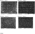
- Sample 1 the cells aggregated in a spherical shape in the lattice, the size of each aggregate was close, and uniform spheroids were formed.
- Sample 2 the cells aggregated to some extent but not in a spherical shape as they were crossing the lattice, and it can not be said that their sizes were uniform. Unlike Sample 1, it is presumed that it may be caused by not having a non-adhesive portion on the lattice.
- Sample 3 although the cells aggregated, they were only somewhat rounded and their sizes were largely different from each other. It is presumed that this is because the adhesive portion was not surrounded by a non-adhesive portion and there was no partition portion.
- sample 4 the cells only spread thinly.
- the evaluation of drug metabolism was performed 1, 7 and 14 days after seeding. After 1, 7 and 14 days, replace medium with induction medium (3-MC 0.333 mM) and incubate for 24 hours. Subsequently, the medium was replaced with a reaction medium (PBS 50 ml, Dicumarol 25 ⁇ M, Probenecid 2 mM, ethoxyresorufin 20 ⁇ M) heated to 37 ° C, after 60 minutes of incubation, the pH was adjusted to 7.4 with HCl. 200 ⁇ l of supernatant and 200 ⁇ l of blank (unreacted reaction medium) were placed in a 96-well plate, and the amount of fluorescence [530/590] was measured with a fluorescence plate reader.
- PBS 50 ml, Dicumarol 25 ⁇ M, Probenecid 2 mM, ethoxyresorufin 20 ⁇ M heated to 37 ° C
- the pH was adjusted to 7.4 with HCl. 200 ⁇ l of supernatant and
- sample 1 it is estimated that the amount of drug metabolism is large, and the oxygen supply is sufficiently carried out on the spheroid being formed.
- Sample 2 although the amount of drug metabolism was relatively large, it was inferior to Sample 1.
- Sample 3 the amount of drug metabolism was as little as 30 to 40% of Sample 1.
- Sample 4 the amount of drug metabolism was greatly reduced.
Landscapes
- Health & Medical Sciences (AREA)
- Engineering & Computer Science (AREA)
- Zoology (AREA)
- Chemical & Material Sciences (AREA)
- Life Sciences & Earth Sciences (AREA)
- Organic Chemistry (AREA)
- Bioinformatics & Cheminformatics (AREA)
- Wood Science & Technology (AREA)
- Biotechnology (AREA)
- Genetics & Genomics (AREA)
- Biochemistry (AREA)
- Biomedical Technology (AREA)
- Clinical Laboratory Science (AREA)
- Sustainable Development (AREA)
- Microbiology (AREA)
- General Engineering & Computer Science (AREA)
- General Health & Medical Sciences (AREA)
- Immunology (AREA)
- Manufacturing & Machinery (AREA)
- Mechanical Engineering (AREA)
- Physics & Mathematics (AREA)
- General Physics & Mathematics (AREA)
- Apparatus Associated With Microorganisms And Enzymes (AREA)
- Micro-Organisms Or Cultivation Processes Thereof (AREA)
- Shaping Of Tube Ends By Bending Or Straightening (AREA)
Abstract
Description
- The present invention relates cell culture substrate and manufacturing method thereof.
- Generally, in the field of drug development, a screening test is known in which a drug is administered to a cell mass (spheroid) cultured in a three-dimensional shape to measure its metabolic ability to the drug. In order to increase the efficiency of this metabolic test, in recent years it has been required to cultivate uniform spheroids with high viability using a culture container that can be conveniently prepared. As a container for spheroid culture, as disclosed in
PTL 1, a substrate or the like having an adhesion region and an inhibition region for cells is used as a culture substrate. - [PLT1]
JP2007-269973A - Resins being able to cultivate relatively uniform spheroids and having a property that can be used for an adhesive region or an inhibition region are special and limited(PLT1). It is difficult to synthesize such a special resin, and it takes a long time and high cost.
- Several embodiments of the present invention have been made in view of such circumstances and provide a cell culture substrate which can be conveniently produced using readily available materials and can cultivate uniform spheroids with high viability.
- According to some embodiments of the present invention, a cell culture substrate having an adhesive portion and a non-adhesive portion is provided, wherein the adhesive portion and the non-adhesive portion have a concave-convex shape, and the contact angle of pure water on the non-adhesive portion is larger than that of the adhesive portion.
- The present inventors found out that it is possible to culture uniform spheroids with high viability by using a cell culture substrate comprising an adhesive portion having a concave-convex shape and highly hydrophobic non-adhesive portion having a concave-convex shape different from the adhesive portion even with readily available materials, and thus has come to complete the present invention.
- Various embodiments of the present invention are exemplified below. Embodiments shown below may be combined with each other.
- It is preferred that, pitch P1 of the concave-convex shape of the adhesive portion is larger than pitch P2 of the concave-convex shape of non-adhesive portion.
- It is preferred that, the ratio P1/P2 of the pitch P1 and the pitch P2 is 2 or more.
- It is preferred that, at least a part of the adhesive portion is separated by a partition portion, and the non-adhesive portion is formed on the partition portion.
- It is preferred that, the non-adhesive portion has a plurality of columnar convex portion, the pitch at which the columnar convex portion of the non-adhesive portion is formed is 50 to 2000 nm, the columnar convex portion of the non-adhesive portion has an upper surface area of 1600 nm2 to 4 µm2, and the gap G2 between two adjacent columnar convex portions is in the range of 10 to 1960 nm.
- It is preferred that, the adhesive portion and the non-adhesive portion are made of a same material.
- According to another embodiment of the present invention, a manufacturing method of the cell culture substrate is provided that includes a step of irradiating a photocurable resin composition coated on a substrate with an active energy ray to cure the resin composition to form concave-convex shapes of the adhesive portion and the non-adhesive portion.
- It is preferred that, the concave-convex shapes of the adhesive portion and the non-adhesive portion are formed by a nanoimprint method using a mold.
-
-
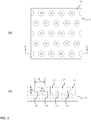
Figs. 1A to 1C show acell culture substrate 1 according to one embodiment of the present invention, whereinFig. 1A is a plan view,Fig. 1B is a cross-sectional view taken along the line A-A, andFig. 1C is a cross-sectional view showing a pattern in which the concave-convex shape according to another embodiment is inverted from the case ofFig. 1B . -
Figs. 2A to 2B are enlarged views of a region X inFig. 1B showing anadhesive portion 3 according to one embodiment of the present invention, whereinFig. 2A is a plan view, andFig. 2B is a cross-sectional view taken along the line B-B. -
Figs. 3A to 3B are enlarged views of a region Y inFig. 1B showing anon-adhesive portion 5 according to one embodiment of the present invention, whereinFig. 3A is a plan view,Fig. 3B is a cross-sectional view taken along the line C-C. -
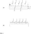
Figs. 4A to 4B are cross-sectional views of thecell culture substrate 1 according to one embodiment of the present invention, whereinFig. 4A shows an example having apartition portion 19, andFig. 4B shows an example without a partition portion. -
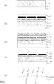
Figs. 5A to 5E show atransparent base 23 provided withlight shielding part 21, whereinFig. 5A is a plan view,Fig. 5B is a cross-sectional view taken along the line D-D, andFigs. 5C to 5E show another example of the method of forming alight shielding pattern 3. -
Figs. 6A to 6C are cross-sectional views showing a first transferred resin layer forming step of the present invention. -
Figs. 7A to 7D are cross-sectional views showing an adhesive portion resin layer forming step of the present invention. -
Figs. 8A to 8E are cross-sectional views showing a composite resin layer forming step of the present inventio. -
Fig. 9 shows SEM images A to D ofsamples 1 to 4. - Preferred embodiments of the present invention are specifically described below with reference to
Figs. 1 to 4 . - As illustrated in
Fig. 1B , acell culture substrate 1 according to one embodiment of the present invention comprises abase 7 and aresin layer 9 on at least one surface of thebase 7, and theresin layer 9 has anadhesive portion 3 and anon-adhesive portion 5. The concave-convex shape of theadhesive portion 3 and thenon-adhesive portion 5 shown inFig. 1B may have a shape in which the concave and convex of only one of theadhesive portion 3 andnon-adhesive portion 5 is reversed, or may have a shape as shown inFig. 1C in which the concave and convex of both are reversed. - It is preferred that, the
non-adhesive portion 5 is arranged in such a manner that it surrounds theadhesive portion 3, and theresin layer 9 is divided into the region ofadhesive portion 3 and the region ofnon-adhesive portion 5. However, it is not necessarily surrounded without a break, and a part may be discontinued. - The shape of the region of the
adhesive portion 3 is not particularly limited, and may be a circle, a polygon, etc. For example, an embodiment in which a square region as shown inFig. 1A is formed is conceivable. - Further, as illustrated in
Fig. 4A , thecell culture substrate 1 may have apartition portion 19 that separates at least a part of the adhesive portion. Further, as illustrated in 4B, thecell culture substrate 1 may not have thepartition portion 19. In order to prevent detachment of the cells from the base during replacement of the medium or the like, it is preferable to have thepartition portion 19. - The material of the
base 7 is preferably, but not particularly limited to a transparent base such as a resin base and a quartz base. From the viewpoint of flexibility, a resin base is more preferable. A resin constituting the resin base is made of, for example, one selected from the group consisting of polyethylene terephthalate, polycarbonate, polyester, polyolefin, polyimide, polysulfone, polyether sulfone, cyclic polyolefin, and polyethylene naphthalate. Further, thebase 7 is preferably in the form of a film having flexibility, and preferably has a thickness ranging from 25 to 500 µm. - A resin constituting the
resin layer 9 is not particularly limited, but it is preferable that theresin layer 9 is made of an inexpensive resin that is relatively easy to obtain and synthesize, such as acrylic resin, methacrylic resin, styrene resin, olefin resin, polycarbonate resin, polyester resin, epoxy resin, and silicone resin. The types of the resin materials of theadhesive portion 3 and thenon-adhesive portion 5 may be different, but from the viewpoint of easiness of manufacture and efficiency, it is preferable to be the same. - As illustrated in
Fig. 2 ,adhesive portion 3 has a concave-convex shape formed by a plurality of adhesiveconvex portions 11 and adhesiveconcave portions 13. The convex portion and the concave portion may be inverted shapes. - The shape of the adhesive
convex portion 11 is not particularly limited, but examples thereof include a column shape (a circular column shape, a polygonal columnar shape, etc.), a truncated cone, a microlens, and the like. The shape of the adhesiveconcave portion 13 is also not particularly limited, but examples thereof include a hole hollowed out in a shape such as a column shape (a circular column shape, a polygonal columnar shape, etc.), a truncated cone, a microlens, and the like. - The pitch P1 at which the adhesive
convex portion 11 or the adhesiveconcave portion 13 is formed may be within a range having adhesiveness to a target cell, and is, for example, 2 to 50 µm, preferably 5 to 20 µm, and more preferably 7 to 15 µm. If the pitch P1 is too small, cells are difficult to adhere. Also, if the pitch P1 is too large, cells are difficult to form spheroids. Specifically, the pitch P1 is, for example, 2, 3, 4, 5, 6, 7, 8, 9, 10, 11, 12, 13, 14, 15, 16, 17, 18, 19, 20, 25, 30, 35, 40, 45, 50 µm, and may be within the range between any two of the numerical values exemplified here. The concave-convex shape formed by the adhesiveconvex portion 11 and the adhesiveconcave portion 13 may be regular or irregular, but is preferably regular from the viewpoint of working efficiency. In the case where the concave-convex shape is formed regularly, the distance between the tips of many convex portions or concave portions constituting the concave-convex shape is defined as "pitch". In the case where the concave-convex shape is formed irregularly, the average value of the distances between the tips of the many convex portions or concave portions constituting the concave-convex shape is defined as "pitch". - The height H1 of the adhesive
convex portion 11 is not particularly limited, but is, for example, 1 to 20 µm, preferably 1 to 10 µm, more preferably 1 to 5 µm. If the height H1 is too low, cells are less likely to form spheroids, and if it is too high, the adhesiveconvex portion 11 tends to collapse easily. - A typical example of the adhesive portion has a plurality of columnar convex portions. The area of the upper surface of the columnar convex portion of the adhesive portion may be within a range having adhesiveness to the target cell, and is, for example, 1 to 2400 µm2, preferably 16 to 360 µm2, more preferably 36 to 196 µm2. The gap G1 between two adjacent columnar convex portions may be within a range having adhesiveness to a target cell, and is, for example, 1 to 49 µm, preferably 4 to 19 µm, more preferably 6 to 14 µm.
- As illustrated in
Fig. 3 , theadhesive portion 3 has a concave-convex shape formed by a plurality of non-adhesiveconvex portion 15 and non-adhesiveconcave portion 17. The convex portion and the concave portion may be inverted. - Further, the contact angle of water on the
non-adhesive portion 5 is not particularly limited but is larger than that of theadhesive portion 3. If the contact angle is larger than that of theadhesive portion 3, cells are difficult to adhere to thenon-adhesive portion 5 and are easy to form spheroids. The contact angle of water on thenon-adhesive portion 5 is, for example, 90 to 180 °, preferably 105 to 180 °, more preferably 110 to 180 °, further preferably 115 to 180 °. - The shape of the non-adhesive
convex portion 15 is not particularly limited, but examples thereof include a column shape (a circular column shape, a polygonal columnar shape, etc.), a truncated cone, a microlens, and the like. The shape of the non-adhesiveconcave portion 17 is also not particularly limited, but examples thereof include a hole hollowed out in a shape such as a column shape (a circular column shape, a polygonal columnar shape, etc.), a truncated cone, a microlens, and the like. - The pitch P2 at which the non-adhesive
convex portion 15 or the non-adhesiveconcave portion 17 is formed is 50 to 2000 nm, preferably 100 to 1000 nm, more preferably 150 to 800 nm. If the pitch P2 is too small, cells can not recognize the concave and convex, and there is no discrimination between adhesiveness and non-adhesiveness. If P2 is too large, cells tend to adhere. Specifically, the pitch P2 is, for example, 50, 60, 70, 80, 90, 100, 150, 200, 250, 300, 350, 400, 450, 500, 550, 600, 650, 700, 750, 800, 850, 900, 950, 1000, 1250, 1500, 1750, 2000 nm, and may be within the range between any two of the numerical values exemplified here. The concave-convex shape formed by the non-adhesiveconvex portion 15 and the non-adhesiveconcave portion 17 may be regular or irregular, but is preferably regular from the viewpoint of working efficiency. In the case where the concave-convex shape is formed regularly, the distance between the tips of many convex portions or concave portions constituting the concave-convex shape is defined as "pitch". In the case where the concave-convex shape is formed irregularly, the average value of the distances between the tips of the many convex portions or concave portions constituting the concave-convex shape is defined as "pitch". - The pitch P1 of the concave-convex shape of the
adhesive portion 3 is larger than the pitch P2 of the concave-convex shape of thenon-adhesive portion 5. The larger the pitch, the smaller the contact angle of water and the higher the adhesiveness to cells tends to be. On the other hand, the smaller the pitch, the larger the contact angle of water and the lower the adhesiveness to cells tend to be. Therefore, by surrounding the region of the concave-convex shape with a large pitch by the region of the concave-convex shape with a small pitch, spheroid can be easily formed. Preferably, the ratio P1/P2 of the pitch P1 and the pitch P2 is 2 or more, more preferably 5 or more, further preferably 10 or more. When P1/P2 is large, there is a tendency that the difference in adhesiveness tends to be large, and it is possible to cultivate spheroids more efficiently because the cells are more likely to gather. The upper limit of P1/P2 is not particularly specified, but is, for example, 200. - The height H2 of the non-adhesive
convex portion 15 is not particularly limited, but is, for example, 50 to 2000 nm. The height H2 is preferably 100 to 1000 nm, and more preferably 150 to 800 nm. If the height H2 is too low, cells tend to adhere, and if it is too high, the non-adhesiveconvex portion 15 tends to collapse easily. - A typical example of the the non-adhesive portion has a plurality of columnar convex portions, more specifically, a plurality of convex portions with circular column shape. The area of the upper surface of the columnar convex portion of the non-adhesive portion may be within a range in which the adhesion to the target cell is low, and is, for example, 1600 nm2 to 4 µm2. This area is preferably 810 nm2 to 1 µm2, more preferably 0.02 to 0.6 µm2. The gap G2 between two adjacent columnar convex portions may be within a range in which the adhesion to the target cell is low, and is, for example, 10 to 1960 nm, preferably 60 to 960 nm, and more preferably 110 to 760 nm.
- A fluorine atom-containing layer may be provided in such a manner that the fluorine atom-containing layer covers the non-adhesive
convex portion 15 and non-adhesiveconcave portion 17. fluorine atom-containing layer may contain a fluorine atom, and its thickness and composition are not limited. By providing the fluorine atom-containing layer it becomes difficult for the cells to adhere. The fluorine atom-containing layer preferably contains a fluorine-containing group. The fluorine-containing group is, in one example, a perfluoroalkyl group, more specifically a perfluoroalkylsilane group. The number of carbon atoms of the perfluoroalkyl group is, for example, 1 to 10, specifically 1, 2, 3, 4, 5, 6, 7, 8, 9, 10, and it may be within the range between any two of the numerical values exemplified here. fluorine-containing group is preferably chemically bonded to the non-adhesiveconvex portion 15 and the non-adhesiveconcave portion 17, or the inorganic film. In general, the inorganic film has high adhesiveness to theresin layer 9, and the fluorine-containing group tends to form a strong chemical bond to the inorganic film. Therefore, by providing the inorganic film between the non-adhesiveconvex portion 15, the non-adhesiveconcave portion 17 and the fluorine atom-containing layer, the fluorine atom-containing layer is firmly held on the non-adhesiveconvex portion 15 and the non-adhesiveconcave portion 17. Examples of the inorganic film include an inorganic oxide film, an inorganic nitride film, an inorganic oxynitride film, and the like. Examples of the inorganic element constituting the inorganic film include silicon and aluminum. The inorganic film is, for example, a silicon dioxide film or an aluminum oxide film. The thickness of the inorganic film is not particularly limited but is, for example, 1 to 20 nm. - The fluorine atom-containing layer, in one example, can be formed by forming an inorganic film on the non-adhesive
convex portion 15 and the non-adhesiveconcave portion 17, and reacting the inorganic film with a fluorine-containing silane coupling agent. The fluorine-containing silane coupling agent is, for example, a perfluoroalkyltrialkoxy (methoxy, ethoxy, etc.) silane. Since even when a fluorine-containing silane coupling agent is allowed to act on the non-adhesiveconvex portion 15 and the non-adhesiveconcave portion 17 without forming an inorganic film, it is preferable to previously form the inorganic film on the non-adhesiveconvex portion 15 and the non-adhesiveconcave portion 17. An example of the fluorine-containing silane coupling agent is OPTOOL DSX (manufactured by Daikin Industries, Ltd.). - The area of the region of the
adhesive portion 3 may be appropriately adjusted according to the type of cells to be cultured and the intended use of the spheroid, and the area is not particularly limited, but is, for example, 25 to 1000000 µm2, preferably 100 to 250000 µm2, more preferably 2500 to 40000 µm2. When the shape of the region of theadhesive portion 3 is a square, the length of one side is 5 to 1000 µm, preferably 10 to 500 µm, more preferably 50 to 200 µm. - If the region of the
non-adhesive portion 5 is too large with respect to the region of theadhesive portion 3, spheroids are difficult to form because the cells are difficult to move to the region of theadhesive portion 3. Therefore, the ratio of the area of the region of thenon-adhesive portion 5 to the total area of region of theadhesive portion 3 and the region of thenon-adhesive portion 5 is preferably, for example, 80% or less, more preferably 50% or less, further preferably 25% or less. - As illustrated in
Fig. 4A , in the case of having thepartition portion 19 that separates at least a part of theadhesive portion 3, preferably, thepartition portion 19 is arranged in such a manner that it surrounds theadhesive portion 3 to form a region of theadhesive portion 3. However, it is not necessarily surrounded without a break, and a part may be discontinued. The shape of the region of theadhesive portion 3 is not particularly limited but may be a circle or a polygon such as a quadrangle. Preferably, thenon-adhesive portion 5 is formed on the partition portion. Thenon-adhesive portion 5 may be formed on a part of the partition portion, and is preferably formed in such a manner that thenon-adhesive portion 5 covers at least most of the upper surface of thepartition portion 19. Thenon-adhesive portion 5 may cover the entire surface of thepartition portion 19. - The height H3 of the
partition portion 19 is not particularly limited, but is, for example, 5 to 100 µm, preferably 10 to 50 µm, more preferably 15 to 25 µm. If the height H3 is too low, the cells tend to be peeled off due to water flow or the like. If the height H3 is too high, oxygen supply can not be sufficiently carried out and the cell viability is lowered. As illustrated inFig. 4A , the height H3 is the height from the upper end of the adhesiveconvex portion 11 to the upper end of the partition portion including the non-adhesive portion. - Next, a manufacturing method of a cell culture substrate will be described with reference to
Figs. 5 to 8 . - In one embodiment of the present invention, a manufacturing method of a cell culture substrate having a partition portion comprises: a non-adhesive portion transfer resin layer forming step, an adhesive portion resin layer forming step, and a composite resin layer forming step.
- Each step will be described in more detail below.
- First, as illustrated in
Fig. 6A , a first photocurable resin composition is applied on atransparent base 23 having alight shielding part 21 as shown inFig. 5A to form a first transferredresin layer 25. - The
transparent base 23 is formed from a transparent material, such as a resin base, a quartz base, and a silicone base. The material is preferably, but not particularly limited to, a resin base. This is because use of a resin base enables a cell culture substrate obtained in a desired size (available in a large area) by the method of the present invention. A resin constituting the resin base is made of, for example, one selected from the group consisting of polyethylene terephthalate, polycarbonate, polyester, polyolefin, polyimide, polysulfone, polyether sulfone, cyclic polyolefin, and polyethylene naphthalate. Thetransparent base 23 preferably has flexibility, and when such a resin base is used, may be a laminate of same or different bases or a laminate of a resin composition in a film form on the resin base. The resin base preferably has a thickness ranging from 25 to 500 µm. - The
light shielding part 21 provided in thetransparent base 23 is a pattern utilized as a mask in the composite shape forming step. As illustrated inFigs. 8B to 8E , anadhesive portion 3 corresponding to thelight shielding part 21, apartition portion 19, and anon-adhesive portion 5 on the partition portion are formed in acomposite resin layer 45. In an active energy ray irradiation step illustrated inFig. 8B , a region whereactive energy rays 29 is shielded by thelight shielding part 21 becomes theadhesive portion 3. The "active energy ray" is the generic name for energy lines capable of curing a photocurable resin composition, such as UV light, visible light, and electron beams. The shape of thelight shielding part 21 is not particularly limited, but may be a square shape as illustrated inFig. 5A , a polygon such as a pentagon or a hexagon, a circle, or the like, and corresponds to the region of theadhesive portion 3. - The
light shielding part 21 may be formed by patterning after deposition of a light shielding material (for example, a metal material, such as Cr) on thetransparent base 23 by sputtering or formed by printing a pattern of a light shielding material by a method, such as ink jet printing and screen printing. As illustrated inFigs. 5B to 5C , thelight shielding part 21 may be formed on the side of asurface 23a of thetransparent base 23 to apply the first photocurable resin composition, or as illustrated inFig. 5D , may be formed on aback side 23b of thetransparent base 23. Thelight shielding part 21, as illustrated inFig. 5B , may be formed flush with thetransparent base 23, may be formed on a flat surface of thetransparent base 23 as illustrated inFig. 5C , or may be mounted in thetransparent base 23 as illustrated inFig. 5E . - The first photocurable resin composition constituting the first transferred
resin layer 25 contains a monomer and a photoinitiator and is cured by irradiation with an active energy ray. - Examples of the monomer include photopolymerizable monomers to form a acrylic resin, a methacrylic resin, a styrene resin, an olefin resin, a polycarbonate resin, a polyester resin, an epoxy resin, a silicone resin, and the like, and a photopolymerizable acrylic monomer and/ or methacrylic monomer is preferred.
- The photoinitiator is a component to be added to accelerate polymerization of a monomer and is preferably contained 0.1 parts by mass or more based on 100 parts by mass of the monomer. The upper limit of the photoinitiator content is not particularly defined but, for example, 20 parts by mass based on 100 parts by mass of the monomer.
- The first photocurable resin composition of the present invention may contain components, such as a solvent, a polymerization inhibitor, a chain transfer agent, an antioxidant, a photosensitizer, a filler, and a leveling agent, without affecting the properties of the first photocurable resin composition.
- The first photocurable resin composition may be manufactured by mixing the above components in a known method. The first photocurable resin composition may be applied on the
transparent base 23 by a method, such as spin coating, spray coating, bar coating, dip coating, die coating, and slit coating, to form the first transferredresin layer 25. - The first transferred
resin layer 25 is generally a transparent resin layer and has a thickness from 100 nm to 1 mm and preferably from 5 to 500 µm. With such a thickness, it is easy to perform imprinting processing and it is possible to form a reverse pattern of a non-adhesive portion. - Then, as illustrated in
Figs. 6A to 6C , with afirst pattern 28 of afirst mold 27 pressed against the first transferredresin layer 25, the first transferredresin layer 25 is irradiated with theactive energy ray 29 through thefirst mold 27, and thereby the non-adhesive portiontransfer resin layer 31 with thefirst pattern 28 transferred thereto is formed. - The
first mold 27 has thefirst pattern 28. In the present embodiment, thefirst pattern 28 is a desired pattern of anon-adhesive portion 5. - The
first mold 27 is made of a transparent material such as a resin base, a quartz base, and a silicone base, and can be formed of the same material as thetransparent base 23. - The
first mold 27 may be pressed against the first transferredresin layer 25 at a pressure that allows transfer of the shape of thefirst pattern 28 to the first transferredresin layer 25. - The first transferred
resin layer 25 may be irradiated with theactive energy ray 29 at an amount of the integral light to sufficiently cure the first transferredresin layer 25. The amount of the integral light is, for example, 100 to 10000 mJ/ cm2. By the irradiation with theactive energy ray 29, the first transferredresin layer 25 is cured to form, as illustrated inFig. 6C , the firstreverse pattern 32 in which thefirst pattern 28 is inverted, that is, the non-adhesive portiontransfer resin layer 31 on which the inverted pattern of the desirednon-adhesive portion 5 is formed. - First, as illustrated in
Fig. 7A , a second photocurable resin composition is applied on thebase 7 to form a second transferredresin layer 33. - The above descriptions on the first photocurable resin composition apply to the second photocurable resin composition as long as not being inconsistent with the spirit. The type of the second photocurable resin composition may be same as or different from that of the first photocurable resin composition. The second transferred
resin layer 33 obtained by applying the second photocurable resin composition is generally a transparent resin layer, and has a thickness of 1 µm to 1 mm, preferably 50 to 500 µm. With such a thickness, it is easy to perform imprinting processing and it is possible to form an adhesive portion. - Then, as illustrated in
Figs. 7B to 7D , with asecond pattern 36 of asecond mold 35 pressed against the second transferredresin layer 33, the second transferredresin layer 33 is irradiated with the active energy ray to cure the second transferredresin layer 33, and thereby the adhesiveportion resin layer 39 is formed. - The
second mold 35 has thesecond pattern 36. In the present embodiment, thesecond pattern 36 is a desired reverse pattern of anadhesive portion 3. - When the
base 7 is transparent, irradiation with theactive energy ray 29 may be performed from the side of the base. Thesecond mold 35 may be formed of a transparent material such as a resin base, a quartz base, a silicone base, or a metal material. - The
second mold 35 may be pressed against the second transferredresin layer 33 at a pressure that allows transfer of the shape of thesecond pattern 36 to the second transferredresin layer 33. - The second transferred
resin layer 33 may be irradiated with theactive energy ray 29 at an amount of the integral light to sufficiently cure the second transferredresin layer 33. The amount of the integral light is, for example, 100 to 10000 mJ/ cm2. By the irradiation with theactive energy ray 29, the second transferredresin layer 33 is cured to form, as illustrated inFig. 7D , the secondreverse pattern 40 in which the second pattern36 is inverted, that is, the adhesiveportion resin layer 39 on which the desirednon-adhesive portion 5 is formed. - First, as illustrated in
Fig. 8A , a third photocurable resin composition is applied on the adhesiveportion resin layer 39 to form a third transferredresin layer 41. - The above descriptions on the first photocurable resin composition apply to the second photocurable resin composition as long as not being inconsistent with the spirit. The type of the third photocurable resin composition may be same as or different from that of the first photocurable resin composition, and may be same as or different from that of the second photocurable resin composition. the third transferred
resin layer 41 obtained by applying the third photocurable resin composition is generally a transparent resin layer, and has a thickness of 10 µm to 1 mm, preferably 50 to 500 µm. With such a thickness, it is easy to perform imprinting processing and it is possible to form a partition portion and a non-adhesive portion. - Then, as illustrated in
Figs. 8B to 8E , with a non-adhesive portiontansfer resin layer 31 as a mold pressed against the third transferredresin layer 41, the third transferredresin layer 41 is irradiated with the active energy ray to cure the third transferredresin layer 41, and thereby thecomposite resin layer 45 is formed. - The non-adhesive portion
tansfer resin layer 31 may be pressed against the third transferredresin layer 41 at a pressure that allows transfer of the shape of the non-adhesive portiontansfer resin layer 31 to the third transferredresin layer 41. - The third transferred
resin layer 41 is irradiated with theactive energy ray 29 the from the non-adhesive portiontransfer resin layer 31. - The third transferred
resin layer 41 may be irradiated with theactive energy ray 29 at an amount of the integral light to sufficiently cure the third transferredresin layer 41. The amount of the integral light is, for example, 100 to 10000 mJ/ cm2. By the irradiation with theactive energy ray 29, in the region not shielded by thelight shielding part 21, the third photocurable resin composition filled in the gap of the adhesiveportion resin layer 39 is cured and the third transferredresin layer 41 to which the reverse pattern of the non-adhesive portiontransfer resin layer 31 was transferred is cured, and thereby thecomposite resin layer 45 is formed. In this step, thepartition portion 19 shown inFig. 8E and thenon-adhesive portion 5 on thepartition portion 19 are formed in the region where the third photocurable resin composition was cured. On the other hand, theadhesive portion 3 remains intact in the region where theactive energy ray 29 was shielded by thelight shielding part 21 and the third photocurable resin composition was not cured. - Then, as illustrated in
Figs. 8D to 8E , the non-adhesive portiontansfer resin layer 31 is removed and thirdphotocurable resin composition 42 remaining on theadhesive portion 3 is removed with solvent to obtain the structure shown inFig. 8E , and the production of the cell culture substrate is completed. - By using the
composite resin layer 45 formed above, it is possible to prepare a mold having the reverse pattern of thecomposite resin layer 45, and by using this mold, a cell culture substrate having the same pattern as that of thecomposite resin layer 45 can be parpared at once. - In the case of not having the partition portion portion, it is possible to manufacture the cell culture substrate as shown in
Fig. 4B by using a mold having theadhesive portion 3 and the reverse pattern of thenon-adhesive portion 5. - Hereinafter, the preparation of the cell culture substrate sample used for cell culture and the evaluation of drug metabolism will be described.
- First, a photocurable resin composition was prepared by blending a photopolymerizable monomer and a photoinitiator in the proportions shown below.
-
- Ethylene oxide modified trimethylolpropane triacrylate (Manufactured by Osaka Organic Chemical Industry Ltd.; Name of product: Viscoat # 360): 50 parts by mass
- Ethylene oxide modified bisphenol A diacrylate (Manufactured by Osaka Organic Chemical Industry Ltd.; Name of product: Viscoat # 700HV): 20 parts by mass
- Tripropylene glycol diacrylate (Manufactured by Osaka Organic Chemical Industry Ltd.; Name of product: Viscoat # 310HP): 30 parts by mass
- 1-hydroxycyclohexyl phenyl ketone (Manufactured by BASF Japan; product name: Irgacure 184): 5 parts by mass
- As illustrated in
Fig. 5 , the photocurable resin composition prepared above was applied to the PET base 47 provided with thelight shielding part 21 as a plurality of squares at a thickness of 10 µm with a bar coater, and a lamination was carried out on a mold of nanopillar having a circular column shape (pitch: 150 nm, height: 250 nm, diameter: 100 nm) with a roller from above in such a manner that the coated resin surface is pressed against the mold. Thereafter, UV irradiation was performed from the mold side at an amount of the integral light of 500 mJ/ cm2 to cure the photocurable resin composition. The mold and the resin-cured PET base were peeled off to prepare a nanohole transfer resin layer having the reverse shape of the mold. - The photocurable resin composition prepared above was applied to the PET base at a thickness of 10 µm with a bar coater, and a lamination was carried out on a mold of nanohole having a hexagonal columnar shape (honeycomb) (pitch :12 µm, depth: 5 µm, parallel two side width: 17 µm) with a roller from above in such a manner that the coated resin surface is pressed against the mold. Thereafter, UV irradiation was performed from the PET base side at an amount of the integral light of 500mJ / cm2 to cure the photocurable resin composition. The mold and the resin-cured PET base were peeled off to prepare a nanopillar transfer resin layer having the reverse shape of the mold.
- The photocurable resin composition prepared above was applied to the nanopillar transfer resin layer at a thickness of 10 µm with a bar coater, and a lamination was carried out on the nanohole transfer resin layer from above using the nanohole transfer resin layer as a mold in such a manner that the coated resin surface is pressed against the nanohole transfer resin layer. Thereafter, UV irradiation was performed from the nanohole transfer resin layer at an amount of the integral light of 500 mJ/ cm2 to cure the photocurable resin composition. The nanohole transfer resin layer and the nanopillar transfer resin layer were peeled off, and the uncured photocurable resin composition remaining on the nanopillar transfer resin layer was removed with isopropyl alcohol to prepare a cell culture substrate.
- A cell culture substrate was prepared in the same manner as in the composite resin layer forming step of
Sample 1, except that instead of using the nanohole transfer resin layer as the mold, a flat one having the samelight shielding part 21 in lattice shape and not having the concave-convex shape was used. - A cell culture substrate was prepared only by the adhesive portion resin layer forming step of
Sample 1. - The photocurable resin composition prepared above was applied to the PET base at a thickness of 10 µm with a bar coater, and UV irradiation was performed from the PET base side at an amount of the integral light of 500 mJ/ cm2 to cure the photocurable resin composition.
- A part of
Sample 1 was excised, the shape was observed using a scanning electron microscope (model: JSM-7800F, manufactured by JEOL Ltd.), and each part was measured using software (PC-SUM) attached to the same microscope. The results for the adhesive portion and the non-adhesive portion are shown in Table 1, and the results for the partition portion are shown in Table 2. In thesample 1, the upper surface area of the partition portion is substantially equal to the area of the region of the non-adhesive portion.[Table 1] Table 1 Adhesive Portion Non-adhesive Portion Shape Hexagonal Column Circular Column Pitch 12 µm 150 nm Height 5 µm 250 nm Width / Diameter 10 µm 100 nm Upper Surface Area 195 µm2 10000πnm2 [Table 2] Table 1 Partition Portion Width 3 µm Height 12 µm Per Unit Area of Separated Adhesion Portion 95×95 µm2 Per Unit Area of Upper Surface of Partition Portion 2000 µm2 - With respect to the obtained
Sample 1, 0.5µl of ion-exchanged water was dropped on the surface of the adhesive portion and the non-adhesive portion ofSample 1, and the contact angle of water (water contact angle) was measured at 25°C using a contact angle measuring device (manufactured by dataphysics) and found to be 100° and 115° respectively. - The results of the cell culture and drug metabolism using the cell culture substrate of the present invention will be described below.
- The cell culture substrate was placed on the bottom of a 6 -well plate (manufactured by Thermo Fisher Scientific) and immersed in 70% ethanol for 1 hour. Then, it was washed three times with PBS having a pH of 7.4 (hereinafter the same) and dried.
- Next, rat hepatocytes were suspended in DMEM medium (manufactured by Thermo Fisher Scientific), seeded in a well plate at 1 × 10⁵ cells / well and cultured at 37°C under 5% CO2 for 14 days. The medium was exchanged the next day of culture, and thereafter it was exchanged every other day.
- In order to investigate the formation of spheroids, the aggregated shape after 14 days after seeding was observed using SEM. SEM images in the case of using
Samples 1 to 4 are shown inFigs. 9A to 9D . - In
Sample 1, the cells aggregated in a spherical shape in the lattice, the size of each aggregate was close, and uniform spheroids were formed. InSample 2, the cells aggregated to some extent but not in a spherical shape as they were crossing the lattice, and it can not be said that their sizes were uniform. UnlikeSample 1, it is presumed that it may be caused by not having a non-adhesive portion on the lattice. InSample 3, although the cells aggregated, they were only somewhat rounded and their sizes were largely different from each other. It is presumed that this is because the adhesive portion was not surrounded by a non-adhesive portion and there was no partition portion. Insample 4, the cells only spread thinly. - The evaluation of drug metabolism was performed 1, 7 and 14 days after seeding. After 1, 7 and 14 days, replace medium with induction medium (3-MC 0.333 mM) and incubate for 24 hours. Subsequently, the medium was replaced with a reaction medium (PBS 50 ml,
Dicumarol 25 µM,Probenecid 2 mM, ethoxyresorufin 20 µM) heated to 37 ° C, after 60 minutes of incubation, the pH was adjusted to 7.4 with HCl. 200 µl of supernatant and 200 µl of blank (unreacted reaction medium) were placed in a 96-well plate, and the amount of fluorescence [530/590] was measured with a fluorescence plate reader. - The evaluation of drug metabolism of
Samples 1 to 4 is shown in Table 3.[Table 3] Table 3 Samples Amount of Drug Metabolism (µM/1×105 cells) 1 day later 7 days later 14 days later Example 1 1 4.8 6.4 7.8 Comparative Example 1 2 2.5 3.2 6.6 Comparative Example 2 3 3.7 4.0 5.2 Comparative Example 3 4 2.7 2.5 2.6 - In
sample 1, it is estimated that the amount of drug metabolism is large, and the oxygen supply is sufficiently carried out on the spheroid being formed. InSample 2, although the amount of drug metabolism was relatively large, it was inferior toSample 1. InSample 3, the amount of drug metabolism was as little as 30 to 40% ofSample 1. InSample 4, the amount of drug metabolism was greatly reduced. - 1: Cell Culture Substrate, 3: Adhesive Portion, 5: Non-Adhesive Portion, 19: Partition portion, 29: Active Energy Ray, P1: Pitch of Concave-Convex Shape of Adhesive Portion, P2: Pitch of Concave-Convex Shape of Non-Adhesive Portion, G2: Gap Between Two Adjacent Columnar Convex Portions
Claims (8)
- A cell culture substrate having an adhesive portion and a non-adhesive portion, wherein
the adhesive portion and the non-adhesive portion have concave-convex shapes, and
a contact angle of pure water on the non-adhesive portion is larger than that of the adhesive portion. - The cell culture substrate of Claim 1, wherein
pitch P1 of the concave-convex shape of the adhesive portion is larger than pitch P2 of the concave-convex shape of the non-adhesive portion. - The cell culture substrate of Claim 2, wherein
the ratio P1/P2 of the pitch P1 and the pitch P2 is 2 or more. - The cell culture substrate of any one of Claims 1 to 3, wherein
at least a part of the adhesive portion is separated by a partition portion, and
the non-adhesive portion is formed on the partition portion. - The cell culture substrate of any one of Claims 2 to 4, wherein
the non-adhesive portion has a plurality of columnar convex portions,
the pitch at which the columnar convex portion of the non-adhesive portion is formed is 50 to 2000 nm,
the columnar convex portion of the non-adhesive portion has an upper surface area of 1600 nm2 to 4 µm2, and
the gap G2 between two adjacent columnar convex portions is in the range of 10 to 1960 nm. - The cell culture substrate of any one of Claims 1 to 5, wherein
the adhesive portion and the non-adhesive portion are made of a same material. - A manufacturing method of the cell culture substrate of Claims 1 to 6, comprising
a step of irradiating, with an active energy ray, a photocurable resin composition coated on a substrate to cure the resin composition to form concave-convex shapes of the adhesive portion and the non-adhesive portion. - The manufacturing method of the cell culture substrate of Claim 7, wherein
the concave-convex shapes of the adhesive portion and the non-adhesive portion are formed by a nanoimprint method using a mold.
Applications Claiming Priority (2)
| Application Number | Priority Date | Filing Date | Title |
|---|---|---|---|
| JP2016008809 | 2016-01-20 | ||
| PCT/JP2017/001689 WO2017126589A1 (en) | 2016-01-20 | 2017-01-19 | Cell culture substrate and method for producing same |
Publications (2)
| Publication Number | Publication Date |
|---|---|
| EP3406700A1 true EP3406700A1 (en) | 2018-11-28 |
| EP3406700A4 EP3406700A4 (en) | 2019-01-23 |
Family
ID=59361719
Family Applications (1)
| Application Number | Title | Priority Date | Filing Date |
|---|---|---|---|
| EP17741466.1A Withdrawn EP3406700A4 (en) | 2016-01-20 | 2017-01-19 | Cell culture substrate and method for producing same |
Country Status (6)
| Country | Link |
|---|---|
| US (1) | US20210189312A1 (en) |
| EP (1) | EP3406700A4 (en) |
| JP (1) | JPWO2017126589A1 (en) |
| CN (1) | CN108473929A (en) |
| TW (1) | TW201730330A (en) |
| WO (1) | WO2017126589A1 (en) |
Families Citing this family (2)
| Publication number | Priority date | Publication date | Assignee | Title |
|---|---|---|---|---|
| CN109810895B (en) * | 2019-02-27 | 2021-12-03 | 西北工业大学 | Open type three-dimensional cell culture chip based on contour microcolumn and preparation technology thereof |
| WO2021024943A1 (en) * | 2019-08-02 | 2021-02-11 | 積水化学工業株式会社 | Scaffold material for cell culture and cell culture container |
Family Cites Families (11)
| Publication number | Priority date | Publication date | Assignee | Title |
|---|---|---|---|---|
| JP4950426B2 (en) * | 2005-02-17 | 2012-06-13 | 株式会社日立製作所 | Nerve cell culture method, neuron culture substrate and method for producing neuron system |
| US20090057960A1 (en) * | 2005-03-30 | 2009-03-05 | Zeon Corporation | Resin mold and process for producing a molded article using the mold |
| JP5397934B2 (en) * | 2006-02-21 | 2014-01-22 | Scivax株式会社 | Spheroids and method for producing the same |
| JP2009213421A (en) * | 2008-03-11 | 2009-09-24 | Fujifilm Corp | Method and apparatus for culturing cell |
| WO2012086028A1 (en) * | 2010-12-22 | 2012-06-28 | 株式会社日立製作所 | Culture substrate and culture sheet |
| JP2012249547A (en) * | 2011-05-31 | 2012-12-20 | Oji Holdings Corp | Cell culture substrate and method for manufacturing the same |
| US20140093962A1 (en) * | 2012-10-01 | 2014-04-03 | The Regents Of The University Of Michigan | Non-adherent cell support and manufacturing method |
| CN103122311B (en) * | 2013-01-15 | 2015-05-27 | 西北工业大学 | Flexible three-dimensional single-cell targeted cultivating chip and controllable preparation method thereof |
| CN104745445B (en) * | 2013-12-30 | 2018-04-27 | 中国科学院深圳先进技术研究院 | A kind of three-dimensional microflow control chip for building cellular network and preparation method thereof |
| TWI663472B (en) * | 2014-07-25 | 2019-06-21 | Soken Chemical & Engineering Co., Ltd. | Manufacturing method of fine structure |
| CN204608029U (en) * | 2015-04-24 | 2015-09-02 | 何向锋 | A kind of sunken cellular type single cell clone plate for isolated culture |
-
2017
- 2017-01-16 TW TW106101400A patent/TW201730330A/en unknown
- 2017-01-19 EP EP17741466.1A patent/EP3406700A4/en not_active Withdrawn
- 2017-01-19 JP JP2017562874A patent/JPWO2017126589A1/en active Pending
- 2017-01-19 US US16/071,165 patent/US20210189312A1/en not_active Abandoned
- 2017-01-19 CN CN201780007100.9A patent/CN108473929A/en active Pending
- 2017-01-19 WO PCT/JP2017/001689 patent/WO2017126589A1/en not_active Ceased
Also Published As
| Publication number | Publication date |
|---|---|
| CN108473929A (en) | 2018-08-31 |
| US20210189312A1 (en) | 2021-06-24 |
| EP3406700A4 (en) | 2019-01-23 |
| TW201730330A (en) | 2017-09-01 |
| WO2017126589A1 (en) | 2017-07-27 |
| JPWO2017126589A1 (en) | 2018-11-15 |
Similar Documents
| Publication | Publication Date | Title |
|---|---|---|
| CN102791452B (en) | Resin mold | |
| CN106104841B (en) | Nanostructures for white light color-forming OLED devices | |
| JP5576822B2 (en) | Method for removing foreign matter adhering to the mold | |
| KR20130138723A (en) | Resin mold for nanoimprinting and manufacturing method thereof | |
| US11693156B2 (en) | Optical body, film adhesive body, and method for manufacturing optical body | |
| TW201206689A (en) | Method for producing product having uneven microstructure on surface thereof | |
| JP5879942B2 (en) | Cell culture substrate manufacturing method, cell culture substrate, and cell sheet manufacturing method using the same | |
| TWI605928B (en) | Photocurable resin composition for imprint, manufacturing method and structure of structure using the resin composition | |
| TWI600671B (en) | Imprinting photo-curable resin composition, method for producing imprinting mold, and imprinting mold | |
| CN103909757A (en) | Flexible printed circuit board and manufacturing method thereof and method for manufacturing substrate for liquid crystal panel | |
| CN108539054A (en) | The preparation method of cathode insulated column of organic luminous display device | |
| JP6603218B2 (en) | Manufacturing method of fine structure | |
| EP2844448B1 (en) | Process for the manufacture of an optical module with polymer optics | |
| US20210189312A1 (en) | Cell culture substrate and manufacturing method thereof | |
| US20130341823A1 (en) | Mold, method for producing mold, and method for producing nanoimprint film | |
| WO2017057220A1 (en) | Water-repellent member and method for manufacturing same | |
| CN104620138B (en) | Anti-reflection film, method for producing same and display device | |
| TWI331961B (en) | ||
| US20150079341A1 (en) | Fabrication method of resin compact, resin compact, and mold | |
| KR20110118018A (en) | Manufacturing method of antireflection film | |
| CN104932195B (en) | Composite nano-imprinting soft template and preparation method thereof | |
| JP2014072319A (en) | Production method of resist substrate, production method of replica template, and nano-imprint lithography method | |
| JP2019041719A (en) | Cell culture structure, cell culture vessel and method for producing cell culture structure | |
| TWI571381B (en) | Protective film and manufacturing method thereof | |
| JP2010032603A (en) | Method for forming negative photosensitive resist pattern, and printing plate |
Legal Events
| Date | Code | Title | Description |
|---|---|---|---|
| STAA | Information on the status of an ep patent application or granted ep patent |
Free format text: STATUS: THE INTERNATIONAL PUBLICATION HAS BEEN MADE |
|
| PUAI | Public reference made under article 153(3) epc to a published international application that has entered the european phase |
Free format text: ORIGINAL CODE: 0009012 |
|
| STAA | Information on the status of an ep patent application or granted ep patent |
Free format text: STATUS: REQUEST FOR EXAMINATION WAS MADE |
|
| 17P | Request for examination filed |
Effective date: 20180816 |
|
| AK | Designated contracting states |
Kind code of ref document: A1 Designated state(s): AL AT BE BG CH CY CZ DE DK EE ES FI FR GB GR HR HU IE IS IT LI LT LU LV MC MK MT NL NO PL PT RO RS SE SI SK SM TR |
|
| AX | Request for extension of the european patent |
Extension state: BA ME |
|
| A4 | Supplementary search report drawn up and despatched |
Effective date: 20190103 |
|
| RIC1 | Information provided on ipc code assigned before grant |
Ipc: B29C 59/02 20060101ALI20181219BHEP Ipc: B29C 59/00 20060101AFI20181219BHEP Ipc: C12M 1/00 20060101ALI20181219BHEP Ipc: B29C 45/00 20060101ALN20181219BHEP Ipc: C12M 1/20 20060101ALI20181219BHEP Ipc: B29C 33/38 20060101ALI20181219BHEP |
|
| DAV | Request for validation of the european patent (deleted) | ||
| DAX | Request for extension of the european patent (deleted) | ||
| STAA | Information on the status of an ep patent application or granted ep patent |
Free format text: STATUS: THE APPLICATION IS DEEMED TO BE WITHDRAWN |
|
| 18D | Application deemed to be withdrawn |
Effective date: 20190802 |