EP3406569A2 - Injection type dissolved air flotation water treatment apparatus - Google Patents
Injection type dissolved air flotation water treatment apparatus Download PDFInfo
- Publication number
- EP3406569A2 EP3406569A2 EP18182100.0A EP18182100A EP3406569A2 EP 3406569 A2 EP3406569 A2 EP 3406569A2 EP 18182100 A EP18182100 A EP 18182100A EP 3406569 A2 EP3406569 A2 EP 3406569A2
- Authority
- EP
- European Patent Office
- Prior art keywords
- water
- mixing
- coagulation
- treatment apparatus
- basin
- Prior art date
- Legal status (The legal status is an assumption and is not a legal conclusion. Google has not performed a legal analysis and makes no representation as to the accuracy of the status listed.)
- Granted
Links
Images



Classifications
-
- C—CHEMISTRY; METALLURGY
- C02—TREATMENT OF WATER, WASTE WATER, SEWAGE, OR SLUDGE
- C02F—TREATMENT OF WATER, WASTE WATER, SEWAGE, OR SLUDGE
- C02F1/00—Treatment of water, waste water, or sewage
- C02F1/24—Treatment of water, waste water, or sewage by flotation
-
- B—PERFORMING OPERATIONS; TRANSPORTING
- B01—PHYSICAL OR CHEMICAL PROCESSES OR APPARATUS IN GENERAL
- B01D—SEPARATION
- B01D21/00—Separation of suspended solid particles from liquids by sedimentation
- B01D21/0084—Enhancing liquid-particle separation using the flotation principle
-
- B—PERFORMING OPERATIONS; TRANSPORTING
- B01—PHYSICAL OR CHEMICAL PROCESSES OR APPARATUS IN GENERAL
- B01D—SEPARATION
- B01D21/00—Separation of suspended solid particles from liquids by sedimentation
- B01D21/01—Separation of suspended solid particles from liquids by sedimentation using flocculating agents
-
- B—PERFORMING OPERATIONS; TRANSPORTING
- B03—SEPARATION OF SOLID MATERIALS USING LIQUIDS OR USING PNEUMATIC TABLES OR JIGS; MAGNETIC OR ELECTROSTATIC SEPARATION OF SOLID MATERIALS FROM SOLID MATERIALS OR FLUIDS; SEPARATION BY HIGH-VOLTAGE ELECTRIC FIELDS
- B03D—FLOTATION; DIFFERENTIAL SEDIMENTATION
- B03D1/00—Flotation
- B03D1/14—Flotation machines
- B03D1/1431—Dissolved air flotation machines
-
- C—CHEMISTRY; METALLURGY
- C02—TREATMENT OF WATER, WASTE WATER, SEWAGE, OR SLUDGE
- C02F—TREATMENT OF WATER, WASTE WATER, SEWAGE, OR SLUDGE
- C02F1/00—Treatment of water, waste water, or sewage
- C02F1/52—Treatment of water, waste water, or sewage by flocculation or precipitation of suspended impurities
- C02F1/5209—Regulation methods for flocculation or precipitation
-
- C—CHEMISTRY; METALLURGY
- C02—TREATMENT OF WATER, WASTE WATER, SEWAGE, OR SLUDGE
- C02F—TREATMENT OF WATER, WASTE WATER, SEWAGE, OR SLUDGE
- C02F1/00—Treatment of water, waste water, or sewage
- C02F1/52—Treatment of water, waste water, or sewage by flocculation or precipitation of suspended impurities
- C02F1/5281—Installations for water purification using chemical agents
-
- B—PERFORMING OPERATIONS; TRANSPORTING
- B03—SEPARATION OF SOLID MATERIALS USING LIQUIDS OR USING PNEUMATIC TABLES OR JIGS; MAGNETIC OR ELECTROSTATIC SEPARATION OF SOLID MATERIALS FROM SOLID MATERIALS OR FLUIDS; SEPARATION BY HIGH-VOLTAGE ELECTRIC FIELDS
- B03D—FLOTATION; DIFFERENTIAL SEDIMENTATION
- B03D1/00—Flotation
- B03D1/14—Flotation machines
- B03D1/1412—Flotation machines with baffles, e.g. at the wall for redirecting settling solids
-
- B—PERFORMING OPERATIONS; TRANSPORTING
- B03—SEPARATION OF SOLID MATERIALS USING LIQUIDS OR USING PNEUMATIC TABLES OR JIGS; MAGNETIC OR ELECTROSTATIC SEPARATION OF SOLID MATERIALS FROM SOLID MATERIALS OR FLUIDS; SEPARATION BY HIGH-VOLTAGE ELECTRIC FIELDS
- B03D—FLOTATION; DIFFERENTIAL SEDIMENTATION
- B03D1/00—Flotation
- B03D1/14—Flotation machines
- B03D1/24—Pneumatic
- B03D1/242—Nozzles for injecting gas into the flotation tank
-
- B—PERFORMING OPERATIONS; TRANSPORTING
- B03—SEPARATION OF SOLID MATERIALS USING LIQUIDS OR USING PNEUMATIC TABLES OR JIGS; MAGNETIC OR ELECTROSTATIC SEPARATION OF SOLID MATERIALS FROM SOLID MATERIALS OR FLUIDS; SEPARATION BY HIGH-VOLTAGE ELECTRIC FIELDS
- B03D—FLOTATION; DIFFERENTIAL SEDIMENTATION
- B03D2203/00—Specified materials treated by the flotation agents; Specified applications
- B03D2203/008—Water purification, e.g. for process water recycling
-
- C—CHEMISTRY; METALLURGY
- C02—TREATMENT OF WATER, WASTE WATER, SEWAGE, OR SLUDGE
- C02F—TREATMENT OF WATER, WASTE WATER, SEWAGE, OR SLUDGE
- C02F1/00—Treatment of water, waste water, or sewage
- C02F1/44—Treatment of water, waste water, or sewage by dialysis, osmosis or reverse osmosis
-
- C—CHEMISTRY; METALLURGY
- C02—TREATMENT OF WATER, WASTE WATER, SEWAGE, OR SLUDGE
- C02F—TREATMENT OF WATER, WASTE WATER, SEWAGE, OR SLUDGE
- C02F1/00—Treatment of water, waste water, or sewage
- C02F1/52—Treatment of water, waste water, or sewage by flocculation or precipitation of suspended impurities
- C02F1/5236—Treatment of water, waste water, or sewage by flocculation or precipitation of suspended impurities using inorganic agents
-
- C—CHEMISTRY; METALLURGY
- C02—TREATMENT OF WATER, WASTE WATER, SEWAGE, OR SLUDGE
- C02F—TREATMENT OF WATER, WASTE WATER, SEWAGE, OR SLUDGE
- C02F1/00—Treatment of water, waste water, or sewage
- C02F1/52—Treatment of water, waste water, or sewage by flocculation or precipitation of suspended impurities
- C02F1/54—Treatment of water, waste water, or sewage by flocculation or precipitation of suspended impurities using organic material
- C02F1/56—Macromolecular compounds
-
- C—CHEMISTRY; METALLURGY
- C02—TREATMENT OF WATER, WASTE WATER, SEWAGE, OR SLUDGE
- C02F—TREATMENT OF WATER, WASTE WATER, SEWAGE, OR SLUDGE
- C02F2103/00—Nature of the water, waste water, sewage or sludge to be treated
- C02F2103/08—Seawater, e.g. for desalination
-
- C—CHEMISTRY; METALLURGY
- C02—TREATMENT OF WATER, WASTE WATER, SEWAGE, OR SLUDGE
- C02F—TREATMENT OF WATER, WASTE WATER, SEWAGE, OR SLUDGE
- C02F2201/00—Apparatus for treatment of water, waste water or sewage
- C02F2201/002—Construction details of the apparatus
-
- C—CHEMISTRY; METALLURGY
- C02—TREATMENT OF WATER, WASTE WATER, SEWAGE, OR SLUDGE
- C02F—TREATMENT OF WATER, WASTE WATER, SEWAGE, OR SLUDGE
- C02F2209/00—Controlling or monitoring parameters in water treatment
- C02F2209/06—Controlling or monitoring parameters in water treatment pH
-
- C—CHEMISTRY; METALLURGY
- C02—TREATMENT OF WATER, WASTE WATER, SEWAGE, OR SLUDGE
- C02F—TREATMENT OF WATER, WASTE WATER, SEWAGE, OR SLUDGE
- C02F2301/00—General aspects of water treatment
- C02F2301/04—Flow arrangements
- C02F2301/043—Treatment of partial or bypass streams
-
- C—CHEMISTRY; METALLURGY
- C02—TREATMENT OF WATER, WASTE WATER, SEWAGE, OR SLUDGE
- C02F—TREATMENT OF WATER, WASTE WATER, SEWAGE, OR SLUDGE
- C02F2301/00—General aspects of water treatment
- C02F2301/04—Flow arrangements
- C02F2301/046—Recirculation with an external loop
-
- C—CHEMISTRY; METALLURGY
- C02—TREATMENT OF WATER, WASTE WATER, SEWAGE, OR SLUDGE
- C02F—TREATMENT OF WATER, WASTE WATER, SEWAGE, OR SLUDGE
- C02F2303/00—Specific treatment goals
- C02F2303/26—Reducing the size of particles, liquid droplets or bubbles, e.g. by crushing, grinding, spraying, creation of microbubbles or nanobubbles
Landscapes
- Chemical & Material Sciences (AREA)
- Life Sciences & Earth Sciences (AREA)
- Engineering & Computer Science (AREA)
- Environmental & Geological Engineering (AREA)
- Hydrology & Water Resources (AREA)
- Water Supply & Treatment (AREA)
- Organic Chemistry (AREA)
- Chemical Kinetics & Catalysis (AREA)
- General Chemical & Material Sciences (AREA)
- Biotechnology (AREA)
- Physical Water Treatments (AREA)
- Separation Of Suspended Particles By Flocculating Agents (AREA)
- Inorganic Chemistry (AREA)
Abstract
Description
- This application claims priority to Korean Application No.
10-2015-0062717 filed on May 4, 2015 - The present disclosure relates to a multibubble injection type DAF (Dissolved Air Flotation) water treatment apparatus, and more particularly, to a multibubble injection type DAF (Dissolved Air Flotation) water treatment apparatus which supplies fine bubbles injected through injection of saturated water to a lower area of a separation zone as well as a lower area of a contact zone of a flotation basin, thereby improving removal efficiency of flocs.
- In general, a water treatment apparatus is an apparatus which produces fresh water using seawater to utilize the fresh water as water for living, eating or industrial use or properly treat raw water to purify waste water. Such a water treatment apparatus includes a device for removing foreign matters mixed in raw water.
- As a unit process for removing foreign matters, there is DAF (Dissolved Air Flotation). The dissolved air flotation is a widely applied technology for various water treatment and sewage treatment processes or a pretreatment process for seawater desalination facilities. The dissolved air flotation is a technology of putting a coagulant, an aid coagulant, a pH regulator and so on in feed water to be treated in order to coagulate suspended particles, which is difficult to be removed through precipitation, such as alga and organic compounds, contained in feed water, injecting micro bubbles into the coagulated matters to combine the micro bubbles with the suspended particles, and floating and removing the suspended particles. In general, a DAF water treatment apparatus includes a mixing and coagulation basin (or a mixing basin), a flocculation basin and a flotation basin, and the flotation basin is divided into a contact zone and a separation zone.
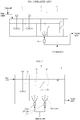
- Referring to
FIG. 1 , a related DAF water treatment apparatus will be described. First, when a coagulant is inserted into feed water to flocculate suspended particles of low density, which is contained in the feed water, in a mixing andcoagulation basin 1. - "Floc" means a large mass that fine particles, such as suspended solids, organic matters and inorganic matters, contained in the raw water are flocculated by the coagulant, and generally means a collected thing formed by flocculation of particles of 0.1µm or more. Flocs of a small size or density which cannot be removed through filtration or precipitation are floated onto the surface of water to be removed using the dissolved air flotation water treatment apparatus.
- The flocs generated and grown up in the mixing and
coagulation basin 1 flow into a flotation basin located at a rear end. The flocs flown into acontact zone 2 are floated to the surface of water by colliding and combining with fine bubbles injected from a lower part of thecontact zone 2, and then, are removed through a scum removal device in aseparation zone 3. In connection with the summary of the dissolved air flotation apparatus, please refer toFIG. 1 ofUS Patent Publication No. 2012-0193294 entitled 'Dissolved gas flotation pressure reduction nozzle published on August 02, 2012. - The related DAF water treatment apparatus separates some of treated water which is an end product by a pipe and supplies compressed air of 4 to 7 bars to saturate the treated water. So, a rapid drop of pressure occurs, and then, micro bubbles are supplied to the
contact zone 2 through anozzle 4 mounted at the lower part of thecontact zone 2. - In the meantime, formation and growing of the flocs in the mixing and
coagulation basin 1 are influenced by raw water conditions, such as seawater temperature, polluted states and the containing degree of suspended matters, and coagulation conditions, such as stirring intensity, residence time and amounts of added chemicals. Accordingly, the flocs cannot perfectly develop in the mixing andcoagulation basin 1, and hence, fine flocs are formed and cannot float properly or grow up into large flocs inside theseparation zone 3 located at the downstream of thecontact zone 2. - Because all of recycle flows in which compressed air is saturated are supplied only to the
contact zone 2, the flocs which grow too late at the downstream of the mixing andcoagulation basin 1 do not have a sufficient opportunity to come into contact with the micro bubbles and flow into the rear end of the system. Therefore, the related dissolved air flotation system has a disadvantage in that quality of the treated water is deteriorated and it has influences on the following processes. - In
KR 10 2006 0114493 - Accordingly, the present disclosure has been made to solve the above-mentioned problems and it is an object of the present disclosure to provide a multibubble injection type DAF (Dissolved Air Flotation) water treatment apparatus which can control some of micro bubbles to be supplied not only to a contact zone but also to a separation zone so that remaining flocs which are not in contact and are not combined with the micro bubbles at the contact zone and a bubble layer (an upper part of the separation zone) additionally come into contact with the micro bubbles in a lower part (below of the bubble layer) of the separation zone, thereby remarkably improving removal of the floes.
- The object is solved by the features of the independent claims. Preferred embodiments are given in the dependent claims.
- To accomplish the above object, according to a first exemplary embodiment, there is provided a multibubble injection type DAF (Dissolved Air Flotation) water treatment apparatus for removing suspended particles contained in feed water to be treated, the multibubble injection type water treatment apparatus including: a mixing and coagulation basin for stirring a coagulant and feed water when the coagulant is injected into the feed water so as to form and grow up flocs through coagulation of suspended particles; a flotation basin for injecting micro bubbles and making the micro bubbles get in contact with the flocs contained in the feed water to form a combined body, raising the combined body to the surface of water and removing the combined body; and micro bubble distributing means having one or more nozzles for receiving saturated water, in which air is saturated, through a saturated water supply pipe in order to spray the saturated water into the flotation basin, wherein the flotation basin is divided into a contact zone, in which the injected micro bubbles and the flocs come into contact with each other, and a separation zone, which removes the combined body rising to the surface of water and discharges treated water to the rear end, by a partition upwardly extending from the bottom surface of the flotation basin, and the micro bubbles injected through the micro bubble distributing means are supplied to the contact zone and the separation zone.
- In this instance, according to a first exemplary embodiment, nozzles are respectively mounted at a lower part of the contact zone and a lower part of the separation zone, the saturated water is supplied to the nozzles through the saturated water supply pipe, and the micro bubbles are injected to the contact zone and the separation zone.
- Moreover, according to a second exemplary embodiment, the nozzle is disposed at the lower part of the contact zone, the partition has a wing part which upwardly extends toward the contact zone at a predetermined distance spaced apart from the bottom end of the partition and an outer end of the wing part is located above a spray hole of the nozzle, so that some of the micro bubbles injected through the nozzle are guided to the separation zone by the wing part.
- In this instance, a plurality of first communication holes are formed from the portion that the wing part is formed to the bottom end of the partition in order to communicate with the separation zone, and the degree of opening of the first communication holes is controlled by first stoppers.
- Furthermore, one or more first turbulence partitions are formed protrudingly from the wing part or the partition, on which the first communication holes are formed, in a micro bubble stay zone surrounded by the wing part and the partition having the first communication holes.
- Additionally, according to a third exemplary embodiment, a two-way nozzle which has spray holes formed in two ways to spray the saturated water to the contact zone and the separation zone is mounted on the partition in order to inject micro bubbles to the contact zone and the separation zone.
- In addition, according to a fourth exemplary embodiment, the micro bubble distributing means includes a container disposed on the bottom of the flotation basin, the upper face of the container becomes the bottom face of the flotation basin and is partitioned into a face exposed toward the contact zone and a face exposed toward the separation zone, and the container has a plurality of second communication holes formed on the upper face thereof, so that the micro bubbles injected from the nozzle mounted at the lower part of the container are supplied to the contact zone and the separation zone through the second communication holes.
- In this instance, the degree of opening of the second communication holes formed on the upper face of the container is controlled by second stoppers, and one or more second turbulence partitions are formed protrudingly from an inner wall of the container, inside the micro bubble stay zone of the container.
- In the meantime, the mixing and coagulation basin includes: a first mixing and coagulation part which is filled with first turbulence derivatives to generate high speed turbulence to first form flocs in the raw water; and a second mixing and coagulation part which is filled with second turbulence derivatives to generate turbulence slower than the turbulence of the first mixing and coagulation part so as to grow up the flocs in the raw water passing the first mixing and coagulation part.
- In this instance, the mixing and coagulation basin further includes a porous separation membrane for partitioning the first mixing and coagulation part from the second mixing and coagulation part in order to maintain different turbulence intensities between the first mixing and coagulation part and the second mixing and coagulation part.
- Moreover, the first turbulence derivatives are mesh-type materials which are stacked manifold or a plurality of fiber aggregates which get tangled together, and the second turbulence derivatives are a plurality of pall ring type materials.
- In the meantime, the multibubble injection type DAF water treatment apparatus further includes a micro bubble forming part for forming saturated water using some of the feed water at the upstream side of the mixing and coagulation basin and supplying the saturated water to the nozzle through the saturated water supply pipe.
- In this instance, the micro bubble forming part includes: an intake pipe for supplying air to the separated feed water; a mixing pump for forcedly transferring the supplied air and the feed water; and a saturator for saturating the supplied air in the transferred feed water.
- Furthermore, the micro bubble forming part further includes a supplement injection part for supplying a supplement to make the formed micro bubbles have positive charges, and the supplement injection part is disposed on an upstream side pipe (a) of the intake pipe, a pipe (b) between the intake pipe and the mixing pump or a pipe (c) between the mixing pump and the saturator.
- Additionally, the micro bubble forming part further includes a strainer for removing solids through pretreatment of the separated feed water.
- As described above, the multibubble injection type DAF water treatment apparatus can supply some of micro bubbles not only to the contact zone but also to the separation zone so that the flocs which are not combined with the micro bubbles at the contact zone and the bubble layer can come into contact with the micro bubbles in the separation zone below the bubble layer, thereby remarkably improving removal of the flocs.
- The above and/or other aspects of the disclosure will become apparent and more readily appreciated from the following description of the embodiments, taken in conjunction with the accompanying drawings of which:
-
FIG. 1 is a schematic diagram of a related DAF (Dissolved Air Flotation) water treatment apparatus; -
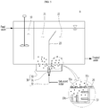
FIG. 2 is a schematic diagram of a DAF (Dissolved Air Flotation) water treatment apparatus according to a first exemplary embodiment; -
FIG. 3 is a schematic diagram of a DAF water treatment apparatus according to a second exemplary embodiment; -
FIG. 4 is a schematic diagram of a DAF water treatment apparatus according to a third exemplary embodiment; -
FIG. 5 is a schematic diagram of a DAF water treatment apparatus according to a fourth exemplary embodiment; -
FIG. 6 is a schematic diagram of a DAF water treatment apparatus according to a fifth exemplary embodiment; and -
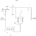
FIG. 7 is a schematic diagram of a DAF water treatment apparatus according to a sixth exemplary embodiment. - Reference will be now made in detail to embodiments of the present disclosure with reference to the attached drawings. It will be understood that words or terms used in the specification and claims shall not be interpreted as the meaning defined in commonly used dictionaries. It will be further understood that the words or terms should be interpreted as having a meaning that is consistent with their meaning in the context of the relevant art and the technical idea of the disclosure.
- The present disclosure provides a DAF (Dissolved Air Flotation) water treatment apparatus (A) which includes a mixing and
coagulation basin 10, aflotation basin 20 divided into acontact zone 21 and aseparation zone 22, and micro bubble distributing means 30 having anozzle 31 for supplying micro bubbles into theflotation basin 20 in order to remove suspended particles contained in feed water to be treated. - The mixing and
coagulation basin 10 in the water treatment apparatus (A) is a unit for stirring a coagulant and feed water when the coagulant is injected into the feed water so as to form and grow up flocs through coagulation of suspended particles, and theflotation basin 20 is a unit for making the flocs grown in the feed water get in contact with the micro bubbles to form a combined body, raising the combined body to the surface of water and removing the combined body. - As described above, in the related water treatment apparatus, because immature flocs do not come into contact with the micro bubbles due to the micro bubbles restrictively injected only to the
contact zone 21 and grow up at the rear end or are turned into fine flocs, it has a bad influence on a rear end unit. Therefore, in order to solve the problem, the main technical feature of the water treatment apparatus according to the present disclosure is to induce the micro bubbles to be injected not only to thecontact zone 21 but also to theseparation zone 22 through the micro bubble distributing means 30. - Therefore, the water treatment apparatus according to the present disclosure can guarantee quality of the treated water stably even though forming and growing conditions of the flocs are changed according to various conditions, such as stirring intensity, seawater temperature or residence time, because the water treatment apparatus can effectively float and remove the flocs which are not removed in the
contact zone 21 or the bubble layer which is an upper part of theseparation zone 22. - The micro
bubble distributing means 30 includes: saturated water supplying means 32 (such as a supply pipe) for supplying saturated water, in which air is saturated, from the outside; and one ormore nozzles 31 which receives the saturated water through the saturated water supplying means to spray the saturated water into theflotation basin 20. The micro bubble distributing means 30 can supply micro bubbles to thecontact zone 21 and theseparation zone 22 in various acceptable forms. Hereinafter, exemplary embodiments of the various forms will be described in detail. - Now, a multiple-effect desalination system which partially injects acid into a partial effect container of high temperature and a desalination method using the same according to an exemplary embodiment will be described. However, the embodiment does not present all technical ideas of the present disclosure. Therefore, it will be understood by those of ordinary skill in the art that there may be various equivalences and modifications at the time that the present disclosure has been filed.
- The water treatment apparatus according to a first exemplary embodiment includes
separate type nozzles contact zone 21 and the lower part of theseparation zone 22 in order to spray the saturated water supplied through the saturated water suppling means 32, and it is illustrated inFIG. 2 . - Because the
nozzles 31 are respectively installed to thecontact zone 21 and theseparation zone 22, installation costs are increased, but it has several advantages in that it is easy to compensate problems of the conventional DAF apparatus which has the nozzle mounted only to thecontact zone 22 and in that it is convenient to control operation of thenozzles 31 individually. - The water treatment apparatus according to a second exemplary embodiment includes a
wing part 23a which protrudes toward thecontact zone 21 at a predetermined height of apartition 23 upwardly extending from the bottom of theflotation basin 20 partitioning thecontact zone 21 and theseparation zone 22. An outer end portion of thewing part 23a is located above a spray hole of thenozzle 31 mounted at the lower part of thecontact zone 21, so that some of the micro bubbles sprayed from thenozzle 31 collide against thewing part 23a and are guided to theseparation zone 22. It is illustrated inFIG. 3 . - The water treatment apparatus according to this example can supply micro bubbles to the
contact zone 21 and theseparation zone 22 using thesingle nozzle 31, and induce the micro bubbles of a proper amount toward theseparation zone 22 because the outer end portion of thewing part 23a is properly mounted to be located above the spray hole of thenozzle 31 or is disposed to be controlled during operation. - In this instance, a plurality of
first communication holes 23b are formed from the portion that thewing part 23a extends to the bottom end of thepartition 23 in order to communicate with theseparation zone 22, so that the micro bubbles guided through thewing part 23a can flow into theseparation zone 22. More preferably,first stoppers 23c which can control the degree of opening of thefirst communication holes 23b may be disposed on thepartition 23 having thefirst communication holes 23b. Preferably, a panel having holes corresponding with thefirst communication holes 23b is combined side by side with thepartition 23 having thefirst communication holes 23b in such a way as to move parallel with thepartition 23, so that the degree of opening of thefirst communication holes 23b can be controlled when the congruence degree between the holes formed in the panel and thefirst communication holes 23b is controlled. - Moreover, in order to generate micro bubbles more effectively by forming turbulence when the saturated water is sprayed onto a micro bubble stay zone (S) surrounded by the
partition 23 having thefirst communication holes 23b, thewing part 23a and the bottom of theflotation basin 20 through thenozzle 31, one or morefirst turbulence partitions 23d may protrude from thepartition 23 or thewing part 23a. - The water treatment apparatus according to a third exemplary embodiment includes a two-way nozzle 31' which has spray holes formed in two directions and is mounted at a predetermined height of the
partition 23 upwardly extending from the bottom of theflotation basin 20 which partitions thecontact zone 21 and theseparation zone 22 in order to spray the saturated water to thecontact zone 21 and theseparation zone 22, so that micro bubbles can be supplied to thecontact zone 21 and theseparation zone 22, and it is illustrated inFIG. 4 . - The water treatment apparatus according to the third exemplary embodiment can supply micro bubbles also to the
separation zone 22 through the single nozzle like the water treatment apparatus according to the second exemplary embodiment, and can control the amount or quality of micro bubbles supplied to thecontact zone 21 or theseparation zone 22 more easily by directly controlling the sprayed state through the two-way nozzle 31' like the water treatment apparatus according to the first exemplary embodiment. - Furthermore, not shown in
FIG. 4 , but the water treatment apparatus according to the third exemplary embodiment may additionally have means for controlling the height of thenozzle 31 mounted on thepartition 23 in order to control positions of the micro bubbles supplied from thenozzle 31 during operation. - The water treatment apparatus according to the fourth exemplary embodiment includes porous container type micro bubble distributing means 30 disposed on the lower part of the
partition 23 upwardly extending from the bottom of theflotation basin 20 which partitions thecontact zone 21 and theseparation zone 22, and it is illustrated inFIG. 5 . - In detail, the micro bubble distributing means 30 according to this embodiment may include a
container 33 disposed on the bottom of theflotation basin 20. The upper face of thecontainer 33 may become the bottom face of theflotation basin 20 in which thepartition 23 is mounted, and the upper face of thecontainer 33 may be partitioned into a face exposed toward thecontact zone 21 and a face exposed toward theseparation zone 22. - In the meantime, the
container 33 has a plurality ofsecond communication holes 33a formed in the upper face thereof, so that the micro bubbles injected from thenozzle 31 mounted at the lower part of thecontainer 33 can be supplied to thecontact zone 21 and theseparation zone 22 through thesecond communication holes 33a. - In this instance, more preferably, the
container 33 may further include asecond stopper 33b disposed on the upper face of thecontainer 33, which has thesecond communication holes 33a, to control the degree of opening of thesecond communication holes 33a. Preferably, a panel having holes corresponding with thesecond communication holes 33a is combined side by side with the upper face of thecontainer 33 having thesecond communication holes 33a in such a way as to move parallel with the upper face of thecontainer 33, so that the degree of opening of thesecond communication holes 33a can be controlled when the congruence degree between the holes formed in the panel and thesecond communication holes 33a is controlled. - Additionally, in order to generate micro bubbles more effectively by forming turbulence when the saturated water is sprayed onto the micro bubble stay zone (S), which is the inner area, surrounded by a body of the
container 33, one or moresecond turbulence partitions 33c may protrude from an inner wall(s) of thecontainer 33. - Furthermore, not shown in
FIG. 5 , but the entire of thecontainer 33 to which thenozzle 31 is combined may move laterally in parallel with the bottom face of theflotation basin 20 at the lower part of theflotation basin 20, so that the exposure degree of the upper face of thecontainer 33 toward thecontact zone 21 or theseparation zone 22 can be controlled. Therefore, the water treatment apparatus according to the fourth exemplary embodiment can control the amount of the micro bubbles supplied to the contact zone and the separation zone. - Nonpowered mixing and coagulation basin including first and second mixing and coagulation parts with different turbulence intensities
- In place of the conventional mixing basin and the conventional flocculation basin which are separately and independently mounted, the water treatment apparatus according to a fifth exemplary embodiment may include a nonpowered mixing and
coagulation basin 10 having first and second mixing and coagulation parts with different turbulence intensities. -
FIG. 6 is a mimetic diagram showing a nonpowered mixing andcoagulation basin 100 according to an embodiment. In more detail, in order to substitute for functions of the conventional mechanical mixing and coagulation basin, the nonpowered mixing and coagulation basin for coagulating a coagulant injected into raw water and particles contained in the raw water to form and grow up flocs includes: a first mixing andcoagulation part 110 which is filled withfirst turbulence derivatives 111 to generate high speed turbulence to first form flocs in the raw water; and a second mixing andcoagulation part 120 which is filled withsecond turbulence derivatives 121 to generate turbulence slower than the turbulence of the first mixing andcoagulation part 110 so as to second grow the flocs in the raw water passing the first mixing andcoagulation part 110, so that the particles contained in the raw water are coagulated into a predetermined size by coming into contact with the coagulant while circulating inside the mixing and coagulation basin by turbulent flows without any stirring power. - The nonpowered mixing and
coagulation basin 100 further includes aporous separation membrane 120 for partitioning the first mixing andcoagulation part 110 from the second mixing andcoagulation part 120 in order to maintain different turbulence intensities between the first mixing andcoagulation part 110 and the second mixing andcoagulation part 120. - First, the first mixing and
coagulation part 110 is a watertight space to form flocs while the particles contained in the raw water are circulated by turbulent flows generated when the raw water flowing into the first mixing andcoagulation part 110 passes the firstturbulent derivatives 111, and has an inflow pipe disposed at the upper side thereof to make the raw water flow in. - The raw water flowing through the inflow pipe in the form of a straight flow forms a highspeed turbulence while passing the first
turbulent derivatives 111 charged in the first mixing andcoagulation part 110, and the particles contained in the raw water and the coagulant come into contact with each other by the turbulence so as to form flocs. The firstturbulent derivatives 111 are mesh-type materials which are stacked manifold or a plurality of fiber aggregates which get tangled together, and preferably, may be stacked asymmetrically not to vertically coincide pores with each other between the mesh-type material having pores and the neighboring mesh-type material. Because the pores of the mesh-type materials are stacked asymmetrically in the vertical direction, the filter media according to the present disclosure can generate turbulences by gravity while the raw water passes the mesh-type materials and control the speed of turbulences generated according to sizes of the pores. - The second mixing and coagulation part is a space for growing the flocs contained in the raw water due to a slow-speed turbulence generated when the treated water passing the first mixing and
coagulation part 110 passes the secondturbulent derivatives 121, and includes a treated water discharge pipe mounted at the lower side for discharging the treated water in which the flocs are contained. - The second
turbulent derivatives 121 has the form that is filled with a plurality of pall ring type materials, preferably, may be formed by a plurality of separate stages filled with the plural pall ring type materials which are stacked in multilayers. - The second mixing and
coagulation part 120 of the nonpowered mixing andcoagulation basin 100 according to the present disclosure can regulate the number of the stages of the separated type, which are respectively filled with the pall ring type materials, according to conditions of the raw water. It is preferable that the stages be disposed to get smaller in packing density of the pall ring type materials toward the downstream side. The reason is that it can make the flocs bigger because turbulence speed gets slower when packing density gets lower. - The
separation membrane 120 is to partition the first mixing andcoagulation part 110 from the second mixing andcoagulation part 120 in order to maintain different turbulence speeds between the first mixing andcoagulation part 110 and the second mixing andcoagulation part 120. The first mixing and coagulation part generates rapid-speed turbulence and the second mixing andcoagulation part 120 generates slow-speed turbulence to form and grow up the flocs by coagulating the particles contained in the raw water. There is no special limit in speed of the rapid-speed turbulence or slow-speed turbulence and the difference in speed of turbulences is caused by a relative difference in turbulence intensity inside the mixing and coagulation basin. - Therefore, in the nonpowered mixing and coagulation basin according to the present disclosure, the first mixing and
coagulation part 110 is disposed above the second mixing andcoagulation part 120, so that the raw water put in the first mixing and coagulation part generates rapid-speed turbulence while passing the firstturbulent derivatives 111 to first form flocs. After that, the raw water goes through the pores of theseparation membrane 130 by gravity, and grows up the flocs formed in the first mixing and coagulation part due to slow-speed turbulence formed while passing a plurality of the stages filled with the secondturbulent derivatives 121 of the second mixing and coagulation part. - As described above, the dissolved air flotation apparatus which includes the mixing and coagulation basin for coagulating foreign matters by injecting the coagulant into the raw water and the flotation basin for floating and removing the flocs by injecting micro bubbles into the raw water may further include the nonpowered mixing and coagulation basin which includes: the first mixing and
coagulation part 110 filled withfirst turbulence derivatives 111 to generate high speed turbulence to form flocs in the raw water; and the second mixing andcoagulation part 120 filled withsecond turbulence derivatives 121 to generate turbulence slower than the turbulence of the first mixing andcoagulation part 110 so as to grow the flocs in the raw water passing the first mixing andcoagulation part 110. The nonpowered mixing andcoagulation basin 100 is disposed at the front end of theflotation basin 20. - Moreover, in order to sufficiently grow the flocs in the raw water passing through the mixing and coagulation basin according to conditions of the raw water, the dissolved air flotation apparatus may further include: an additional coagulation basin (not shown) which has an agitator mounted between the mixing and
coagulation basin 100 and theflotation basin 20; and a bypass channel (not shown) to directly transfer the flocs from the first mixing andcoagulation part 110 to the additional coagulation basin. - The first mixing and
coagulation part 110 is disposed above the second mixing andcoagulation part 130, so that the raw water put in the first mixing and coagulation part passes the second mixing and coagulation part by gravity. - The dissolved air flotation apparatus having the nonpowered mixing and coagulation basin according to the present disclosure can regulate the number of the plural stages of the second mixing and
coagulation part 120 or control the flow through the bypass channel and the agitator according to the conditions of the raw water requiring water treatment. In more detail, in a case that the additional coagulation basin is needed in order to increase coagulation efficiency of the flocs, the agitator included in the additional coagulation basin is operated, and then, a first flow to direct theflotation basin 20 through the second mixing andcoagulation part 120 and the additional coagulation basin from the first mixing andcoagulation part 110 and a second flow to direct theflotation basin 20 through the bypass channel and the additional coagulation basin from the first mixing andcoagulation part 110 are selectively controlled. In a case that the additional coagulation basin 150 is not needed, the agitator is stopped, and then, a third flow to direct theflotation basin 20 through the second mixing andcoagulation part 120 from the first mixing andcoagulation part 110 and a fourth flow to direct theflotation basin 20 through the bypass channel from the first mixing andcoagulation part 110 are selectively controlled. - Therefore, the flow of the treated water can be selectively controlled into the first flow to the fourth flow according to conditions of the raw water, temporary problems and situations, so that operating costs can be reduced.
- [EXAMPLE VI]
- In general, the DAF water treatment apparatus separate some of the treated water which is discharged finally, generates saturated water by injecting compressed air, and then, sprays the saturated water to the separation zone through the nozzle. However, the water treatment apparatus according to a sixth exemplary embodiment of the present disclosure generates saturated water not using treated water but using some of feed water of the upstream side and supplies micro bubbles to the separation zone, and it is illustrated in
FIG. 7 . - In general, because a flow rate of a recycle flow separated from treated water is about 10% to 20% of feed water and an amount of formed micro bubbles is increased as the flow rate of the recycle flow is increased, performance of the apparatus can be improved. However, if the flow rate of the recycle flow is increased, a flow velocity in the
separation zone 22 is increased and the combined body between the flocs and the micro bubbles does not float and is discharged to the following process. - In the meantime, a surface loading rate which is a performance index of the dissolved air flotation apparatus was conventionally 5 m/hr to 15 m/hr which is slower than a theoretical bubble rise speed. Recently, high rate DAF apparatuses with a surface loading rate of 20 m/hr to 40 m/hr have appeared. However, because the surface loading rate is faster than the bubble rise speed, if the
flotation basin 20 is designed in error, contaminants and bubbles are discharged together with the treated water and it may hit the following process. Furthermore, because micro bubbles are created using the recycle flow separated from the finally treated water, the substantive surface loading rate may fall short of the above-mentioned surface loading rate. - Therefore, the water treatment apparatus according to the present disclosure includes a micro
bubble forming part 50 for forming micro bubbles by inducing and saturating air into water separated not from the finally treated water but from the initial feed water so as to enhance efficiency of the apparatus. - In detail, the micro
bubble forming part 50 includes anintake pipe 51 for supplying air to the separated upstream side feed water; a mixing pump 52 for forcedly transferring the supplied air and the feed water; and asaturator 53 for saturating the supplied air in the transferred feed water. - A conventional saturator is a device for dissolving compressed air in treated water induced through a circulating pump. The conventional saturator has a water gathering space formed at a lower part thereof and an area above the water gathering space is filled with a filler, so that saturated water in which compressed air is dissolved is gathered in the water gathering space while the compressed air and water flow into the upper end of the saturator and pass through the filler.
- Such a conventional saturator has a problem of biofouling because microorganisms are formed on the filler disposed in the saturator when air is supplied not to treated water but to feed water, and the problem is more critical in case of a saturator having a high and big pressure container in order to enhance efficiency.
- Therefore, the present disclosure proposes a
new saturator 53 with an improved inner structure which can use not treated water but feed water because solving the problem that saturation efficiency is reduced due to biofouling, does not use an air compressor, and can be operated at pressure of about 3 bar which is lower than pressure of the conventional saturator, 4 bar to 7 bar, so as to reduce operation costs. - Hereinafter, the
saturator 53 according to the exemplary embodiment will be described in detail. The saturator 53 (not shown in the drawing) includes: a housing; a partition which extends in a vertical direction from an inner wall of one side of the housing but does not reach an inner wall of the other side so as to form a flow channel at the inner wall of the other side; and a plurality of fine pores formed in the partition. The saturator which adopts the inner partition structure induces a turbulent flow of the feed water flowing therein and air contained in the feed water, so that the air can be effectively saturated in the feed water even at relatively small operation pressure (about 3 bar) and it can prevent the problem of biofouling by generation of turbulence and can be operated without any air compressor. - Moreover, in order to easily induce electrostatic combination with the flocs formed in the feed water, because micro bubbles must have positive (+) charges, micro bubble ionizers of various types, such as electrolyzers for electrolysis may be adopted. Preferably, a
supplement injection part 54 for supplying a supplement for ionization of micro bubbles may be added. As the supplement, there are ferric salt coagulants, aluminum-based coagulants, and so on. - In this instance, the
supplement injection parts 54 may be disposed at various positions in order to supply the supplement to the feed water inside the pipe, preferably, disposed on an upstream side pipe of theintake pipe 51, on a pipe between theintake pipe 51 and the mixing pump 52 or on a pipe between the mixing pump 52 and thesaturator 53. - In a case that the supplement is supplied to the separated initial feed water, the supplement can be naturally and uniformly mixed during an air supply process through the
intake pipe 51 and during a forcedly transferring process through the mixing pump 52. Alternatively, in a case that the supplement is supplied on the pipe between theintake pipe 51 and the mixing pump 52 or on the pipe between the mixing pump 52 and thesaturator 53, it is easy to control operations through control of the flow rate and pressure of the feed water. - Additionally, the water treatment apparatus according to the present disclosure may further include a
strainer 55 for removing solids through pretreatment of the separated feed water of the upstream side. The strainer means devices for preventing foreign matters from being induced by removing solids contained in a fluid. In general, there are Y-type strainers and U-type strainers which uses a wire mesh container in a steam piping system or a water piping system. Thestrainer 55 is disposed at the upstream side from which the feed water is separated for first preprocessing the feed water in which lots of solids exist compared with treated water, in order to minimize bad influences on each process of the micro bubble forming processes at the rear end. - A comparative experiment for comparing performance of the DAF water treatment apparatus (A) which supplies micro bubbles not only to the
contact zone 21 but also to theseparation zone 22 according to the exemplary embodiment with performance of the conventional DAF water treatment apparatus which supplies micro bubbles only to thecontact zone 21 was carried out. The comparative experiment was carried out at surface loading rate of 30 m/h, at recycle ratio of 10% and at pressure of 5 bar, and turbidities (NTU) and total suspended solids (mg/L) of feed water and treated water were measured in relation to the water treatment apparatus (A) according to the present disclosure and the conventional water treatment apparatus.[Table 1] Conventional Device Present Disclosure Turbidity (NTU) Feed water 10.3 10.3 Treated water 4 2.4 TSS(Total Suspended Solids) (mg/L) Feed water 21.6 21.6 Treated water 4 2 - As seen from the table 1, the water treatment apparatus (A) according to the embodiment of the present disclosure was far better in removal efficiency of contaminants or flocs in feed water than the conventional water treatment apparatus because inducing immature fine flocs or immature flocs, which would grow up too late at the rear end, to additionally come into contact with the micro bubbles.
- Further, the embodiments discussed have been presented by way of example only and not limitation. Thus, the breadth and scope of the disclosure(s) should not be limited by any of the above-described exemplary embodiments, but should be defined only in accordance with the following claims and their equivalents. Moreover, the above advantages and features are provided in described embodiments, but shall not limit the application of the claims to processes and structures accomplishing any or all of the above advantages.
- Additionally, the section headings herein are provided for consistency with the suggestions under 37 CFR 1.77 or otherwise to provide organizational cues. These headings shall not limit or characterize the disclosure(s) set out in any claims that may issue from this disclosure. Specifically and by way of example, although the headings refer to a "Technical Field," the claims should not be limited by the language chosen under this heading to describe the so-called technical field. Further, a description of a technology in the "Background" is not to be construed as an admission that technology is prior art to any disclosure(s) in this disclosure. Neither is the "Brief Summary" to be considered as a characterization of the disclosure(s) set forth in the claims found herein. Furthermore, any reference in this disclosure to "disclosure" in the singular should not be used to argue that there is only a single point of novelty claimed in this disclosure. Multiple disclosures may be set forth according to the limitations of the multiple claims associated with this disclosure, and the claims accordingly define the disclosure(s), and their equivalents, that are protected thereby. In all instances, the scope of the claims shall be considered on their own merits in light of the specification, but should not be constrained by the headings set forth herein.
-
- 1. A multibubble injection type DAF (Dissolved Air Flotation) water treatment apparatus (A) for removing suspended particles contained in feed water to be treated, the DAF water treatment apparatus (A) comprising: a mixing and coagulation basin (10) configured to stir a coagulant and feed water when the coagulant is injected into the feed water so as to form and grow up flocs through coagulation of suspended particles; a flotation basin (20) configured to inject micro bubbles and make the micro bubbles contact with the flocs contained in the feed water to form a combined body, raise the combined body to the surface of water and remove the combined body; and micro bubble distributing means (30) having one or more nozzles (31) configured to receive saturated water, in which air is saturated, through a saturated water supply pipe (32) in order to spray the saturated water into the flotation basin (20), wherein the flotation basin (20) is divided into a contact zone (21), in which the injected micro bubbles and the flocs come into contact with each other, and a separation zone (22), which removes the combined body rising to the surface of water and discharges treated water to a rear end, by a partition (23) upwardly extending from a bottom surface of the flotation basin (20), and wherein the micro bubbles injected through the micro bubble distributing means (30) are supplied to the contact zone (21) and the separation zone (22).
- 2. The multibubble injection type DAF water treatment apparatus according to example 1, wherein nozzles (31a and 31b) are respectively mounted at a lower part of the contact zone (21) and a lower part of the separation zone (22), the saturated water is supplied to the nozzles (31a and 31b) through the saturated water supply pipe (32), and the micro bubbles are injected to the contact zone (21) and the separation zone (22).
- 3. The multibubble injection type DAF water treatment apparatus according to example 1 or 2, wherein the nozzle (31) is disposed at the lower part of the contact zone (21), the partition (23) has a wing part (23a) which upwardly extends toward the contact zone (21) at a predetermined distance spaced apart from the bottom end of the partition (23) and an outer end of the wing part (23a) is located above a spray hole of the nozzle (31), so that some of the micro bubbles injected through the nozzle (31) are guided to the separation zone (22) by the wing part (23a).
- 4. The multibubble injection type DAF water treatment apparatus according to example 3, wherein a plurality of first communication holes (23b) are formed from the portion that the wing part (23a) is formed to the bottom end of the partition (23) in order to communicate with the separation zone (22).
- 5. The multibubble injection type DAF water treatment apparatus according to example 4, wherein a degree of opening of the first communication holes (23b) is controlled by first stoppers (23c).
- 6. The multibubble injection type DAF water treatment apparatus according to example 4 or 5, wherein one or more first turbulence partitions (23d) are formed protrudingly from the wing part (23a) or the partition (23), on which the first communication holes (23b) are formed, in a micro bubble stay zone (S) surrounded by the wing part (23a) and the partition (23) having the first communication holes (23b).
- 7. The multibubble injection type DAF water treatment apparatus according to any one of the preceding examples, wherein a two-way nozzle (31) which has spray holes formed in two directions configured to spray the saturated water to the contact zone (21) and the separation zone (22) is mounted on the partition (23) in order to inject micro bubbles to the contact zone (21) and the separation zone (22).
- 8. The multibubble injection type DAF water treatment apparatus according to any one of the preceding examples, wherein the micro bubble distributing means (30) includes a container (33) disposed on the bottom of the flotation basin (20), wherein an upper face of the container (33) forms at least a part of the bottom face of the flotation basin (20) and is partitioned into a face exposed toward the contact zone (21) and a face exposed toward the separation zone (22), and wherein the container (33) has a plurality of second communication holes (33a) formed on the upper face thereof, so that the micro bubbles injected from the nozzle (31) mounted at the lower part of the container (33) are supplied to the contact zone (21) and the separation zone (22) through the second communication holes (33a).
- 9. The multibubble injection type DAF water treatment apparatus according to example 8, wherein a degree of opening of the second communication holes (33a) formed on the upper face of the container (33) is controlled by second stoppers (33b).
- 10. The multibubble injection type DAF water treatment apparatus according to example 8 or 9, wherein one or more second turbulence partitions (33c) are formed protrudingly from an inner wall of the container (33), inside the micro bubble stay zone (S) of the container (33).
- 11. The multibubble injection type DAF water treatment apparatus according to any one of the preceding examples, wherein the mixing and coagulation basin comprises:a first mixing and coagulation part (11) which is filled with first turbulence derivatives (11a) to generate high speed turbulence to first form flocs in the raw water; and a second mixing and coagulation part (12) which is filled with second turbulence derivatives (12a) to generate turbulence slower than the turbulence of the first mixing and coagulation part (11) so as to grow up the flocs in the raw water passing the first mixing and coagulation part (11).
- 12. The multibubble injection type DAF water treatment apparatus according to example 11, wherein the mixing and coagulation basin (10) further comprises a porous separation membrane (13) configured to partition the first mixing and coagulation part (11) from the second mixing and coagulation part (12) in order to maintain different turbulence intensities between the first mixing and coagulation part (11) and the second mixing and coagulation part (12).
- 13. The multibubble injection type DAF water treatment apparatus according to example 11 or 12, wherein the first turbulence derivatives (11a) are mesh-type materials which are stacked manifold or a plurality of fiber aggregates configured to be tangled together, and the second turbulence derivatives (12a) are a plurality of pall ring type materials.
- 14. The multibubble injection type DAF water treatment apparatus according to any one of the preceding examples 1, further comprising:a micro bubble forming part (50) configured to form saturated water using some of the feed water at the upstream side of the mixing and coagulation basin and to supply the saturated water to the nozzle through the saturated water supply pipe.
- 15. The multibubble injection type DAF water treatment apparatus according to example 14, wherein the micro bubble forming part (50) comprises: an intake pipe (51) configured to supply air to the separated feed water; a mixing pump (52) configured to forcedly transfer the supplied air and the feed water; and a saturator (53) configured to saturate the supplied air in the transferred feed water.
Claims (15)
- A multibubble injection type Dissolved Air Flotation, DAF, water treatment apparatus (A) for removing suspended particles contained in feed water to be treated, the DAF water treatment apparatus (A) comprising:a mixing and coagulation basin (10) configured to stir a coagulant and feed water when the coagulant is injected into the feed water so as to form and grow up flocs through coagulation of suspended particles;a flotation basin (20) configured to inject micro bubbles and make the micro bubbles contact with the flocs contained in the feed water to form a combined body, raise the combined body to the surface of water and remove the combined body; andmicro bubble distributing means (30) having one or more nozzles (31) configured to receive saturated water, in which air is saturated, through a saturated water supply pipe (32) in order to spray the saturated water into the flotation basin (20),wherein the flotation basin (20) is divided into a contact zone (21), in which the injected micro bubbles and the flocs come into contact with each other, and a separation zone (22), which removes the combined body rising to the surface of water and discharges treated water to a rear end, by a partition (23) upwardly extending from a bottom surface of the flotation basin (20),wherein the micro bubbles are injected through the micro bubble distributing means (30) so that the micro bubbles are supplied to both a lower part of the contact zone (21) and a lower part of the separation zone (22), andwherein the mixing and coagulation basin (10) comprises:a first mixing and coagulation part (110) which is filled with first turbulence derivatives (11a) to generate high speed turbulence to first form flocs in the raw water; anda second mixing and coagulation part (120) which is filled with second turbulence derivatives to generate turbulence slower than the turbulence of the first mixing and coagulation part (110) so as to grow up the flocs in the raw water passing the first mixing and coagulation part (110).
- The multibubble injection type DAF water treatment apparatus according to claim 1, wherein the mixing and coagulation basin (10) further comprises a porous separation membrane (130) configured to partition the first mixing and coagulation part (110) from the second mixing and coagulation part (110) in order to maintain different turbulence intensities between the first mixing and coagulation part (110) and the second mixing and coagulation part (120).
- The multibubble injection type DAF water treatment apparatus according to claim 1 or 2, wherein the mixing and coagulation basin (10) is a watertight space to form the flocs while particles contained in the raw water are circulated by turbulent flows and has an inflow pipe disposed at the upper side to enable the raw material to flow in.
- The multibubble injection type DAF water treatment apparatus according to claim 1, 2 or 3, wherein the first turbulence derivatives (11a) are mesh-type materials which are stacked manifold or a plurality of fiber aggregates configured to be tangled together, and the second turbulence derivatives (12a) are a plurality of pall ring type materials.
- The multibubble injection type DAF water treatment apparatus according to any one of the preceding claims, wherein the second mixing and coagulation part (120) includes a treated water discharge pipe mounted at a lower side for discharging the treated water in which the flocs are contained.
- The multibubble injection type DAF water treatment apparatus according to any one of the claims 1 to 5, further comprising an additional coagulation basin having an agitator mounted between the mixing and coagulation basin (10) and the floating basin (20); and a bypass channel to direct transfer the flocs from the first mixing and coagulation part (110) to the additional coagulation basin.
- A multibubble injection type Dissolved Air Flotation, DAF, water treatment apparatus (A) for removing suspended particles contained in feed water to be treated, the DAF water treatment apparatus (A) comprising:a mixing and coagulation basin (10) configured to stir a coagulant and feed water when the coagulant is injected into the feed water so as to form and grow up flocs through coagulation of suspended particles;a flotation basin (20) configured to inject micro bubbles and make the micro bubbles contact with the flocs contained in the feed water to form a combined body, raise the combined body to the surface of water and remove the combined body; andmicro bubble distributing means (30) having one or more nozzles (31) configured to receive saturated water, in which air is saturated, through a saturated water supply pipe (32) in order to spray the saturated water into the flotation basin (20),wherein the flotation basin (20) is divided into a contact zone (21), in which the injected micro bubbles and the flocs come into contact with each other, and a separation zone (22), which removes the combined body rising to the surface of water and discharges treated water to a rear end, by a partition (23) upwardly extending from a bottom surface of the flotation basin (20),wherein the micro bubbles are injected through the micro bubble distributing means (30) so that the micro bubbles are supplied to both a lower part of the contact zone (21) and a lower part of the separation zone (22), anda micro bubble forming part (50) configured to form saturated water using some of the feed water at the upstream side of the mixing and coagulation basin and to supply the saturated water to the nozzle through the saturated water supply pipe.
- The multibubble injection type DAF water treatment apparatus according to claim 7, wherein the micro bubble forming part (50) comprises:an intake pipe (51) configured to supply air to the separated feed water;a mixing pump (52) configured to forcedly transfer the supplied air and the feed water; anda saturator (53) configured to saturate the supplied air in the transferred feed water.
- The multibubble injection type DAF water treatment apparatus according to claim 8, wherein the saturator (53) including:a housing;a partition extending in a vertical direction from an inner wall of one side of the housing without reaching an inner wall of the other side for forming a flow channel at the inner wall,the saturator (53) is configured to induce a turbulent flow of the feed water flowing therein and air contained in the feed water by adopting the inner partition structure.
- The multibubble injection type DAF water treatment apparatus according to claim 7, 8 or 9, further comprising a supplement injection part (54) for supplying a supplement for ionization of micro bubbles.
- The multibubble injection type DAF water treatment apparatus according to claim 10, wherein the supplement is one of the group consisting of ferric salt coagulant or aluminum-based coagulant.
- The multibubble injection type DAF water treatment apparatus according to one of the claims 10 or 11, wherein the supplement injection part (54) is disposed on:an upstream side pipe of the intake pipe (51);on a pipe between the intake pipe (51) and the mixing pump (52); oron a pipe between the mixing pump (52) and the saturator (53).
- The multibubble injection type DAF water treatment apparatus according to one of the claims 7 to 12, further comprising a strainer (55) for removing solids through pretreatment of separated feed water of the upstream side.
- The multibubble injection type DAF water treatment apparatus according to claim 13, wherein the strainer (55) being an U-type or an Y-type strainer
- The multibubble injection type DAF water treatment apparatus according to claim 13 or 14, wherein the strainer (55) being disposed at the upstream side from which the feed water is separated.
Applications Claiming Priority (2)
| Application Number | Priority Date | Filing Date | Title |
|---|---|---|---|
| KR1020150062717A KR101690510B1 (en) | 2015-05-04 | 2015-05-04 | Dissolved air flotation water treatment apparatus injected multiple bubble |
| EP16155269.0A EP3090806B1 (en) | 2015-05-04 | 2016-02-11 | Injection type dissolved air flotation water treatment apparatus |
Related Parent Applications (2)
| Application Number | Title | Priority Date | Filing Date |
|---|---|---|---|
| EP16155269.0A Division EP3090806B1 (en) | 2015-05-04 | 2016-02-11 | Injection type dissolved air flotation water treatment apparatus |
| EP16155269.0A Division-Into EP3090806B1 (en) | 2015-05-04 | 2016-02-11 | Injection type dissolved air flotation water treatment apparatus |
Publications (3)
| Publication Number | Publication Date |
|---|---|
| EP3406569A2 true EP3406569A2 (en) | 2018-11-28 |
| EP3406569A3 EP3406569A3 (en) | 2019-02-27 |
| EP3406569B1 EP3406569B1 (en) | 2020-05-27 |
Family
ID=55701675
Family Applications (2)
| Application Number | Title | Priority Date | Filing Date |
|---|---|---|---|
| EP18182100.0A Active EP3406569B1 (en) | 2015-05-04 | 2016-02-11 | Injection-type flotation water treatment apparatus into which dissolved air is injected |
| EP16155269.0A Active EP3090806B1 (en) | 2015-05-04 | 2016-02-11 | Injection type dissolved air flotation water treatment apparatus |
Family Applications After (1)
| Application Number | Title | Priority Date | Filing Date |
|---|---|---|---|
| EP16155269.0A Active EP3090806B1 (en) | 2015-05-04 | 2016-02-11 | Injection type dissolved air flotation water treatment apparatus |
Country Status (3)
| Country | Link |
|---|---|
| US (1) | US10093554B2 (en) |
| EP (2) | EP3406569B1 (en) |
| KR (1) | KR101690510B1 (en) |
Cited By (1)
| Publication number | Priority date | Publication date | Assignee | Title |
|---|---|---|---|---|
| CN110066008A (en) * | 2019-04-28 | 2019-07-30 | 淮北矿业股份有限公司 | A kind of biochemistry pool compressed-air system for sewage treatment plant |
Families Citing this family (18)
| Publication number | Priority date | Publication date | Assignee | Title |
|---|---|---|---|---|
| KR101875653B1 (en) | 2016-10-10 | 2018-07-06 | 현대자동차 주식회사 | Device for decreasing hydrogen concentration of fuel cell system |
| KR102131735B1 (en) * | 2017-04-26 | 2020-07-08 | 두산중공업 주식회사 | Compact type aeration tank for sewage treatment and sewage treatment system comprising the same |
| KR101979767B1 (en) | 2017-05-31 | 2019-05-17 | 한국건설기술연구원 | High-rate sedimentation-flotation system and operation method using the same |
| CN107601728B (en) * | 2017-11-14 | 2023-12-26 | 河南清波环境工程有限公司 | Air-floatation flocculation sewage treatment system with automatic exhaust and anti-tumbling functions |
| US10245546B1 (en) | 2018-08-22 | 2019-04-02 | H & H Inventions & Enterprises, Inc. | Exhaust gas purification method and system |
| KR102211487B1 (en) * | 2019-05-27 | 2021-02-03 | 서울대학교산학협력단 | High-rate daf using differential bubble size |
| KR102669652B1 (en) | 2019-09-19 | 2024-05-28 | 주식회사 엘지화학 | The Apparatus For Neutralizing/Water Separating Esterification Products And The Method For Thereof |
| KR102614264B1 (en) | 2019-09-19 | 2023-12-18 | 주식회사 엘지화학 | Neutralization/Water Separate Tank For Esterification Products And The Method For Neutralizing/Water Separating Esterification Products |
| CN111018031A (en) * | 2019-11-29 | 2020-04-17 | 安徽节源环保科技有限公司 | Novel air floatation tank |
| CN110921992A (en) * | 2019-12-15 | 2020-03-27 | 刘彬 | Water cleaning system based on air floatation design |
| RU199049U1 (en) * | 2020-02-05 | 2020-08-11 | Борис Семенович Ксенофонтов | WATER FLEET COMBINE FOR WATER PURIFICATION |
| CN111285506A (en) * | 2020-03-30 | 2020-06-16 | 无锡市政设计研究院有限公司 | Pretreatment system and pretreatment method for wastewater membrane treatment process |
| KR20210158010A (en) * | 2020-06-23 | 2021-12-30 | 두산중공업 주식회사 | Submerged type plasma apparatus and water treatment system using the same |
| BR102020014726B1 (en) * | 2020-07-20 | 2021-06-01 | João Carlos Gomes De Oliveira | SEWAGE TREATMENT PROCESS IN CONTINUOUS, LINEAR AND FLEXIBLE CHANNEL, THROUGH A MODIFIED AEROBIC BIOLOGICAL REACTOR SYSTEM, OR TRANSFORMATION OF AN ANAEROBIC BIOLOGICAL REACTOR ALREADY EXISTING IN A FLEXIFIED AEROBIC MODIFIED BIOLOGICAL REACTOR, MODIFIED AEROBIC MODIFICATION SYSTEM |
| US11814303B2 (en) * | 2022-03-14 | 2023-11-14 | Saudi Arabian Oil Company | Utilizing concentrated solar power for water-oil separation |
| CN116395778A (en) * | 2023-03-03 | 2023-07-07 | 广东清研环境科技有限公司 | Water treatment method and air flotation equipment |
| KR20250082585A (en) | 2023-11-30 | 2025-06-09 | 주식회사 연 | Device for water treatment using Dissolved Air Flotation |
| CN117401791B (en) * | 2023-12-13 | 2024-03-08 | 陕西永明煤矿有限公司 | Coal slime water treatment device for coal processing and application method thereof |
Citations (2)
| Publication number | Priority date | Publication date | Assignee | Title |
|---|---|---|---|---|
| KR20060114493A (en) | 2005-05-02 | 2006-11-07 | 유연근 | Wastewater Treatment System |
| US20120193294A1 (en) | 2009-10-09 | 2012-08-02 | Enpure Limited | Dissolved gas flotation pressure reduction nozzle |
Family Cites Families (13)
| Publication number | Priority date | Publication date | Assignee | Title |
|---|---|---|---|---|
| US2242139A (en) * | 1938-03-25 | 1941-05-13 | Walter C Munroe | Method and apparatus for water purification |
| JP2002001011A (en) * | 2000-06-22 | 2002-01-08 | Japan Organo Co Ltd | Flocculation and precipitation apparatus |
| FR2837197B1 (en) * | 2002-03-12 | 2005-01-28 | Ondeo Degremont | METHOD AND DEVICE FOR CLARIFYING LIQUIDS, ESPECIALLY WATER, LOADS OF SUSPENSION MATERIALS |
| KR100804221B1 (en) * | 2006-12-26 | 2008-02-18 | 주식회사 부강테크 | Wastewater Treatment Method Using Pressurized Turbulent Reactor |
| FR2934582B1 (en) * | 2008-07-29 | 2010-09-10 | Otv Sa | PROCESS FOR TREATING A LIQUID BY FLOTATION INDUCED BY FLOATING PARTICLES |
| FR2942220B1 (en) * | 2009-02-16 | 2011-04-08 | Orege | METHOD AND DEVICE FOR PURIFYING LIQUID EFFLUENTS |
| KR101189912B1 (en) | 2009-12-21 | 2012-10-11 | 서울대학교산학협력단 | Apparatus for Treating Waste Water |
| KR100988474B1 (en) * | 2010-06-01 | 2010-10-18 | 주식회사두합크린텍 | Flocculation basin for treatment of drinking water and wastewater |
| KR101095298B1 (en) | 2011-04-26 | 2011-12-16 | 비엔에이치엔지니어링 주식회사 | Water treatment device using floating separation |
| KR101297439B1 (en) * | 2011-05-26 | 2013-08-16 | 서울대학교산학협력단 | Device for Generating Micro Bubble Having Positive Charge and Water Treatment Apparatus Using the Same |
| CA2883928A1 (en) * | 2012-09-04 | 2014-03-13 | Doosan Enpure Limited | Dissolved gas flotation apparatus |
| FR2995603B1 (en) * | 2012-09-19 | 2014-09-26 | Veolia Water Solutions & Tech | WATER TREATMENT METHOD COMPRISING A FLOTATION COMBINED WITH GRAVITY FILTRATION AND CORRESPONDING INSTALLATION |
| JP2016504186A (en) * | 2012-12-07 | 2016-02-12 | アドヴァンスト・ウォーター・リカバリー・エルエルシー | System, apparatus and method for separating material from water |
-
2015
- 2015-05-04 KR KR1020150062717A patent/KR101690510B1/en active Active
-
2016
- 2016-02-11 EP EP18182100.0A patent/EP3406569B1/en active Active
- 2016-02-11 EP EP16155269.0A patent/EP3090806B1/en active Active
- 2016-02-12 US US15/042,487 patent/US10093554B2/en active Active
Patent Citations (2)
| Publication number | Priority date | Publication date | Assignee | Title |
|---|---|---|---|---|
| KR20060114493A (en) | 2005-05-02 | 2006-11-07 | 유연근 | Wastewater Treatment System |
| US20120193294A1 (en) | 2009-10-09 | 2012-08-02 | Enpure Limited | Dissolved gas flotation pressure reduction nozzle |
Cited By (2)
| Publication number | Priority date | Publication date | Assignee | Title |
|---|---|---|---|---|
| CN110066008A (en) * | 2019-04-28 | 2019-07-30 | 淮北矿业股份有限公司 | A kind of biochemistry pool compressed-air system for sewage treatment plant |
| CN110066008B (en) * | 2019-04-28 | 2021-07-30 | 淮北矿业股份有限公司 | A biochemical pond forced air system for sewage treatment plant |
Also Published As
| Publication number | Publication date |
|---|---|
| EP3406569B1 (en) | 2020-05-27 |
| EP3090806A1 (en) | 2016-11-09 |
| EP3406569A3 (en) | 2019-02-27 |
| KR101690510B1 (en) | 2016-12-28 |
| EP3090806B1 (en) | 2019-07-17 |
| US10093554B2 (en) | 2018-10-09 |
| US20160326016A1 (en) | 2016-11-10 |
| KR20160130654A (en) | 2016-11-14 |
Similar Documents
| Publication | Publication Date | Title |
|---|---|---|
| EP3090806B1 (en) | Injection type dissolved air flotation water treatment apparatus | |
| KR101628678B1 (en) | Water treating apparatus using dissolved air floatation including flocculation basin or not | |
| JP5033130B2 (en) | Water purification apparatus and method of implementation | |
| KR100988474B1 (en) | Flocculation basin for treatment of drinking water and wastewater | |
| EP3201137B1 (en) | Water treatment process employing dissolved air flotation to remove suspended solids | |
| KR20160029272A (en) | a simple structured wastewater treatment system using multi step aerating floation method and the wastewater treatment method | |
| RU2303000C2 (en) | Installation for floatation purification of the water | |
| KR20160032067A (en) | a simple structured wastewater treatment system using multi step aerating floation method and the wastewater treatment method | |
| KR101956379B1 (en) | Multiple Floating Dissolved Air Flotation System | |
| JP4930340B2 (en) | Pressure levitation device | |
| JPS6054120B2 (en) | water treatment equipment | |
| KR101610599B1 (en) | the watertreatment device to improve the flexibility of submerged membrane system installed with Dissolved air floatation in high turbidity and algae-rich conditions and the method thereof | |
| KR20170084659A (en) | Multiple Floating Dissolved Air Flotation System | |
| JP4908542B2 (en) | Filtration method, filtration device and filtration pond | |
| KR20190007916A (en) | Energy-saving water treatment system | |
| KR102109402B1 (en) | Apparatus of Treating Effluent from Water Treatment Plant | |
| KR102012965B1 (en) | Dissolved Air Flotation System using ambient air | |
| KR101992302B1 (en) | Dissolved air flotation device capable of controlling treatment level of wastewater | |
| CN211664862U (en) | Anionic surfactant sewage treatment device | |
| CN104968615A (en) | Water treatment method and equipment | |
| KR102720530B1 (en) | Pressurized air lifting system | |
| KR102094978B1 (en) | Dissolved air flotation device capable of increasing organic matter recovery | |
| KR20190042249A (en) | Dissolved air flotation device capable of increasing organic matter recovery and water treatment method using the same | |
| RU183322U1 (en) | PLANT FOR FLOTATION WASTE WATER TREATMENT | |
| KR20180019362A (en) | Simplified seawater desalination plant |
Legal Events
| Date | Code | Title | Description |
|---|---|---|---|
| PUAI | Public reference made under article 153(3) epc to a published international application that has entered the european phase |
Free format text: ORIGINAL CODE: 0009012 |
|
| STAA | Information on the status of an ep patent application or granted ep patent |
Free format text: STATUS: REQUEST FOR EXAMINATION WAS MADE |
|
| 17P | Request for examination filed |
Effective date: 20180706 |
|
| AC | Divisional application: reference to earlier application |
Ref document number: 3090806 Country of ref document: EP Kind code of ref document: P |
|
| AK | Designated contracting states |
Kind code of ref document: A2 Designated state(s): AL AT BE BG CH CY CZ DE DK EE ES FI FR GB GR HR HU IE IS IT LI LT LU LV MC MK MT NL NO PL PT RO RS SE SI SK SM TR |
|
| PUAL | Search report despatched |
Free format text: ORIGINAL CODE: 0009013 |
|
| AK | Designated contracting states |
Kind code of ref document: A3 Designated state(s): AL AT BE BG CH CY CZ DE DK EE ES FI FR GB GR HR HU IE IS IT LI LT LU LV MC MK MT NL NO PL PT RO RS SE SI SK SM TR |
|
| RIC1 | Information provided on ipc code assigned before grant |
Ipc: C02F 1/24 20060101AFI20190122BHEP Ipc: C02F 1/52 20060101ALI20190122BHEP Ipc: B03D 1/14 20060101ALI20190122BHEP Ipc: B03D 1/24 20060101ALN20190122BHEP |
|
| RAP1 | Party data changed (applicant data changed or rights of an application transferred) |
Owner name: DOOSAN HEAVY INDUSTRIES & CONSTRUCTION CO., LTD. |
|
| GRAP | Despatch of communication of intention to grant a patent |
Free format text: ORIGINAL CODE: EPIDOSNIGR1 |
|
| STAA | Information on the status of an ep patent application or granted ep patent |
Free format text: STATUS: GRANT OF PATENT IS INTENDED |
|
| RIC1 | Information provided on ipc code assigned before grant |
Ipc: C02F 1/52 20060101ALI20191011BHEP Ipc: B03D 1/24 20060101ALN20191011BHEP Ipc: B03D 1/14 20060101ALI20191011BHEP Ipc: C02F 1/24 20060101AFI20191011BHEP |
|
| INTG | Intention to grant announced |
Effective date: 20191029 |
|
| RIN1 | Information on inventor provided before grant (corrected) |
Inventor name: PARK, YONG-HAE Inventor name: PARK, BYUNG SUNG |
|
| GRAS | Grant fee paid |
Free format text: ORIGINAL CODE: EPIDOSNIGR3 |
|
| GRAA | (expected) grant |
Free format text: ORIGINAL CODE: 0009210 |
|
| STAA | Information on the status of an ep patent application or granted ep patent |
Free format text: STATUS: THE PATENT HAS BEEN GRANTED |
|
| AC | Divisional application: reference to earlier application |
Ref document number: 3090806 Country of ref document: EP Kind code of ref document: P |
|
| AK | Designated contracting states |
Kind code of ref document: B1 Designated state(s): AL AT BE BG CH CY CZ DE DK EE ES FI FR GB GR HR HU IE IS IT LI LT LU LV MC MK MT NL NO PL PT RO RS SE SI SK SM TR |
|
| REG | Reference to a national code |
Ref country code: GB Ref legal event code: FG4D |
|
| REG | Reference to a national code |
Ref country code: CH Ref legal event code: EP |
|
| REG | Reference to a national code |
Ref country code: AT Ref legal event code: REF Ref document number: 1274387 Country of ref document: AT Kind code of ref document: T Effective date: 20200615 |
|
| REG | Reference to a national code |
Ref country code: DE Ref legal event code: R096 Ref document number: 602016037316 Country of ref document: DE |
|
| REG | Reference to a national code |
Ref country code: LT Ref legal event code: MG4D |
|
| PG25 | Lapsed in a contracting state [announced via postgrant information from national office to epo] |
Ref country code: NO Free format text: LAPSE BECAUSE OF FAILURE TO SUBMIT A TRANSLATION OF THE DESCRIPTION OR TO PAY THE FEE WITHIN THE PRESCRIBED TIME-LIMIT Effective date: 20200827 Ref country code: GR Free format text: LAPSE BECAUSE OF FAILURE TO SUBMIT A TRANSLATION OF THE DESCRIPTION OR TO PAY THE FEE WITHIN THE PRESCRIBED TIME-LIMIT Effective date: 20200828 Ref country code: IS Free format text: LAPSE BECAUSE OF FAILURE TO SUBMIT A TRANSLATION OF THE DESCRIPTION OR TO PAY THE FEE WITHIN THE PRESCRIBED TIME-LIMIT Effective date: 20200927 Ref country code: SE Free format text: LAPSE BECAUSE OF FAILURE TO SUBMIT A TRANSLATION OF THE DESCRIPTION OR TO PAY THE FEE WITHIN THE PRESCRIBED TIME-LIMIT Effective date: 20200527 Ref country code: PT Free format text: LAPSE BECAUSE OF FAILURE TO SUBMIT A TRANSLATION OF THE DESCRIPTION OR TO PAY THE FEE WITHIN THE PRESCRIBED TIME-LIMIT Effective date: 20200928 Ref country code: FI Free format text: LAPSE BECAUSE OF FAILURE TO SUBMIT A TRANSLATION OF THE DESCRIPTION OR TO PAY THE FEE WITHIN THE PRESCRIBED TIME-LIMIT Effective date: 20200527 Ref country code: LT Free format text: LAPSE BECAUSE OF FAILURE TO SUBMIT A TRANSLATION OF THE DESCRIPTION OR TO PAY THE FEE WITHIN THE PRESCRIBED TIME-LIMIT Effective date: 20200527 |
|
| REG | Reference to a national code |
Ref country code: NL Ref legal event code: MP Effective date: 20200527 |
|
| PG25 | Lapsed in a contracting state [announced via postgrant information from national office to epo] |
Ref country code: LV Free format text: LAPSE BECAUSE OF FAILURE TO SUBMIT A TRANSLATION OF THE DESCRIPTION OR TO PAY THE FEE WITHIN THE PRESCRIBED TIME-LIMIT Effective date: 20200527 Ref country code: BG Free format text: LAPSE BECAUSE OF FAILURE TO SUBMIT A TRANSLATION OF THE DESCRIPTION OR TO PAY THE FEE WITHIN THE PRESCRIBED TIME-LIMIT Effective date: 20200827 Ref country code: RS Free format text: LAPSE BECAUSE OF FAILURE TO SUBMIT A TRANSLATION OF THE DESCRIPTION OR TO PAY THE FEE WITHIN THE PRESCRIBED TIME-LIMIT Effective date: 20200527 Ref country code: HR Free format text: LAPSE BECAUSE OF FAILURE TO SUBMIT A TRANSLATION OF THE DESCRIPTION OR TO PAY THE FEE WITHIN THE PRESCRIBED TIME-LIMIT Effective date: 20200527 |
|
| REG | Reference to a national code |
Ref country code: AT Ref legal event code: MK05 Ref document number: 1274387 Country of ref document: AT Kind code of ref document: T Effective date: 20200527 |
|
| PG25 | Lapsed in a contracting state [announced via postgrant information from national office to epo] |
Ref country code: NL Free format text: LAPSE BECAUSE OF FAILURE TO SUBMIT A TRANSLATION OF THE DESCRIPTION OR TO PAY THE FEE WITHIN THE PRESCRIBED TIME-LIMIT Effective date: 20200527 Ref country code: AL Free format text: LAPSE BECAUSE OF FAILURE TO SUBMIT A TRANSLATION OF THE DESCRIPTION OR TO PAY THE FEE WITHIN THE PRESCRIBED TIME-LIMIT Effective date: 20200527 |
|
| PG25 | Lapsed in a contracting state [announced via postgrant information from national office to epo] |
Ref country code: DK Free format text: LAPSE BECAUSE OF FAILURE TO SUBMIT A TRANSLATION OF THE DESCRIPTION OR TO PAY THE FEE WITHIN THE PRESCRIBED TIME-LIMIT Effective date: 20200527 Ref country code: SM Free format text: LAPSE BECAUSE OF FAILURE TO SUBMIT A TRANSLATION OF THE DESCRIPTION OR TO PAY THE FEE WITHIN THE PRESCRIBED TIME-LIMIT Effective date: 20200527 Ref country code: EE Free format text: LAPSE BECAUSE OF FAILURE TO SUBMIT A TRANSLATION OF THE DESCRIPTION OR TO PAY THE FEE WITHIN THE PRESCRIBED TIME-LIMIT Effective date: 20200527 Ref country code: IT Free format text: LAPSE BECAUSE OF FAILURE TO SUBMIT A TRANSLATION OF THE DESCRIPTION OR TO PAY THE FEE WITHIN THE PRESCRIBED TIME-LIMIT Effective date: 20200527 Ref country code: AT Free format text: LAPSE BECAUSE OF FAILURE TO SUBMIT A TRANSLATION OF THE DESCRIPTION OR TO PAY THE FEE WITHIN THE PRESCRIBED TIME-LIMIT Effective date: 20200527 Ref country code: RO Free format text: LAPSE BECAUSE OF FAILURE TO SUBMIT A TRANSLATION OF THE DESCRIPTION OR TO PAY THE FEE WITHIN THE PRESCRIBED TIME-LIMIT Effective date: 20200527 Ref country code: ES Free format text: LAPSE BECAUSE OF FAILURE TO SUBMIT A TRANSLATION OF THE DESCRIPTION OR TO PAY THE FEE WITHIN THE PRESCRIBED TIME-LIMIT Effective date: 20200527 Ref country code: CZ Free format text: LAPSE BECAUSE OF FAILURE TO SUBMIT A TRANSLATION OF THE DESCRIPTION OR TO PAY THE FEE WITHIN THE PRESCRIBED TIME-LIMIT Effective date: 20200527 |
|
| PG25 | Lapsed in a contracting state [announced via postgrant information from national office to epo] |
Ref country code: PL Free format text: LAPSE BECAUSE OF FAILURE TO SUBMIT A TRANSLATION OF THE DESCRIPTION OR TO PAY THE FEE WITHIN THE PRESCRIBED TIME-LIMIT Effective date: 20200527 Ref country code: SK Free format text: LAPSE BECAUSE OF FAILURE TO SUBMIT A TRANSLATION OF THE DESCRIPTION OR TO PAY THE FEE WITHIN THE PRESCRIBED TIME-LIMIT Effective date: 20200527 |
|
| REG | Reference to a national code |
Ref country code: DE Ref legal event code: R097 Ref document number: 602016037316 Country of ref document: DE |
|
| PLBE | No opposition filed within time limit |
Free format text: ORIGINAL CODE: 0009261 |
|
| STAA | Information on the status of an ep patent application or granted ep patent |
Free format text: STATUS: NO OPPOSITION FILED WITHIN TIME LIMIT |
|
| 26N | No opposition filed |
Effective date: 20210302 |
|
| PG25 | Lapsed in a contracting state [announced via postgrant information from national office to epo] |
Ref country code: SI Free format text: LAPSE BECAUSE OF FAILURE TO SUBMIT A TRANSLATION OF THE DESCRIPTION OR TO PAY THE FEE WITHIN THE PRESCRIBED TIME-LIMIT Effective date: 20200527 |
|
| PG25 | Lapsed in a contracting state [announced via postgrant information from national office to epo] |
Ref country code: MC Free format text: LAPSE BECAUSE OF FAILURE TO SUBMIT A TRANSLATION OF THE DESCRIPTION OR TO PAY THE FEE WITHIN THE PRESCRIBED TIME-LIMIT Effective date: 20200527 |
|
| REG | Reference to a national code |
Ref country code: BE Ref legal event code: MM Effective date: 20210228 |
|
| PG25 | Lapsed in a contracting state [announced via postgrant information from national office to epo] |
Ref country code: CH Free format text: LAPSE BECAUSE OF NON-PAYMENT OF DUE FEES Effective date: 20210228 Ref country code: LI Free format text: LAPSE BECAUSE OF NON-PAYMENT OF DUE FEES Effective date: 20210228 Ref country code: LU Free format text: LAPSE BECAUSE OF NON-PAYMENT OF DUE FEES Effective date: 20210211 |
|
| PG25 | Lapsed in a contracting state [announced via postgrant information from national office to epo] |
Ref country code: IE Free format text: LAPSE BECAUSE OF NON-PAYMENT OF DUE FEES Effective date: 20210211 |
|
| PG25 | Lapsed in a contracting state [announced via postgrant information from national office to epo] |
Ref country code: BE Free format text: LAPSE BECAUSE OF NON-PAYMENT OF DUE FEES Effective date: 20210228 |
|
| PG25 | Lapsed in a contracting state [announced via postgrant information from national office to epo] |
Ref country code: CY Free format text: LAPSE BECAUSE OF FAILURE TO SUBMIT A TRANSLATION OF THE DESCRIPTION OR TO PAY THE FEE WITHIN THE PRESCRIBED TIME-LIMIT Effective date: 20200527 |
|
| PG25 | Lapsed in a contracting state [announced via postgrant information from national office to epo] |
Ref country code: HU Free format text: LAPSE BECAUSE OF FAILURE TO SUBMIT A TRANSLATION OF THE DESCRIPTION OR TO PAY THE FEE WITHIN THE PRESCRIBED TIME-LIMIT; INVALID AB INITIO Effective date: 20160211 |
|
| REG | Reference to a national code |
Ref country code: DE Ref legal event code: R082 Ref document number: 602016037316 Country of ref document: DE Representative=s name: TER MEER STEINMEISTER & PARTNER PATENTANWAELTE, DE |
|
| PG25 | Lapsed in a contracting state [announced via postgrant information from national office to epo] |
Ref country code: MK Free format text: LAPSE BECAUSE OF FAILURE TO SUBMIT A TRANSLATION OF THE DESCRIPTION OR TO PAY THE FEE WITHIN THE PRESCRIBED TIME-LIMIT Effective date: 20200527 |
|
| PG25 | Lapsed in a contracting state [announced via postgrant information from national office to epo] |
Ref country code: MT Free format text: LAPSE BECAUSE OF FAILURE TO SUBMIT A TRANSLATION OF THE DESCRIPTION OR TO PAY THE FEE WITHIN THE PRESCRIBED TIME-LIMIT Effective date: 20200527 |
|
| PG25 | Lapsed in a contracting state [announced via postgrant information from national office to epo] |
Ref country code: TR Free format text: LAPSE BECAUSE OF FAILURE TO SUBMIT A TRANSLATION OF THE DESCRIPTION OR TO PAY THE FEE WITHIN THE PRESCRIBED TIME-LIMIT Effective date: 20200527 |
|
| PGFP | Annual fee paid to national office [announced via postgrant information from national office to epo] |
Ref country code: GB Payment date: 20251218 Year of fee payment: 11 |
|
| PGFP | Annual fee paid to national office [announced via postgrant information from national office to epo] |
Ref country code: FR Payment date: 20251208 Year of fee payment: 11 |
|
| PGFP | Annual fee paid to national office [announced via postgrant information from national office to epo] |
Ref country code: DE Payment date: 20251216 Year of fee payment: 11 |