EP3406533A1 - Tamper-evident packaging and flexible material sheet for such packaging - Google Patents
Tamper-evident packaging and flexible material sheet for such packaging Download PDFInfo
- Publication number
- EP3406533A1 EP3406533A1 EP17172650.8A EP17172650A EP3406533A1 EP 3406533 A1 EP3406533 A1 EP 3406533A1 EP 17172650 A EP17172650 A EP 17172650A EP 3406533 A1 EP3406533 A1 EP 3406533A1
- Authority
- EP
- European Patent Office
- Prior art keywords
- panel
- packaging
- tongue
- main panel
- projecting
- Prior art date
- Legal status (The legal status is an assumption and is not a legal conclusion. Google has not performed a legal analysis and makes no representation as to the accuracy of the status listed.)
- Withdrawn
Links
Images


Classifications
-
- B—PERFORMING OPERATIONS; TRANSPORTING
- B65—CONVEYING; PACKING; STORING; HANDLING THIN OR FILAMENTARY MATERIAL
- B65D—CONTAINERS FOR STORAGE OR TRANSPORT OF ARTICLES OR MATERIALS, e.g. BAGS, BARRELS, BOTTLES, BOXES, CANS, CARTONS, CRATES, DRUMS, JARS, TANKS, HOPPERS, FORWARDING CONTAINERS; ACCESSORIES, CLOSURES, OR FITTINGS THEREFOR; PACKAGING ELEMENTS; PACKAGES
- B65D5/00—Rigid or semi-rigid containers of polygonal cross-section, e.g. boxes, cartons or trays, formed by folding or erecting one or more blanks made of paper
- B65D5/02—Rigid or semi-rigid containers of polygonal cross-section, e.g. boxes, cartons or trays, formed by folding or erecting one or more blanks made of paper by folding or erecting a single blank to form a tubular body with or without subsequent folding operations, or the addition of separate elements, to close the ends of the body
- B65D5/10—Rigid or semi-rigid containers of polygonal cross-section, e.g. boxes, cartons or trays, formed by folding or erecting one or more blanks made of paper by folding or erecting a single blank to form a tubular body with or without subsequent folding operations, or the addition of separate elements, to close the ends of the body with end closures formed by inward-folding of self-locking flaps hinged to tubular body
-
- B—PERFORMING OPERATIONS; TRANSPORTING
- B65—CONVEYING; PACKING; STORING; HANDLING THIN OR FILAMENTARY MATERIAL
- B65D—CONTAINERS FOR STORAGE OR TRANSPORT OF ARTICLES OR MATERIALS, e.g. BAGS, BARRELS, BOTTLES, BOXES, CANS, CARTONS, CRATES, DRUMS, JARS, TANKS, HOPPERS, FORWARDING CONTAINERS; ACCESSORIES, CLOSURES, OR FITTINGS THEREFOR; PACKAGING ELEMENTS; PACKAGES
- B65D5/00—Rigid or semi-rigid containers of polygonal cross-section, e.g. boxes, cartons or trays, formed by folding or erecting one or more blanks made of paper
- B65D5/42—Details of containers or of foldable or erectable container blanks
- B65D5/54—Lines of weakness to facilitate opening of container or dividing it into separate parts by cutting or tearing
- B65D5/5405—Lines of weakness to facilitate opening of container or dividing it into separate parts by cutting or tearing for opening containers formed by erecting a blank in tubular form
- B65D5/542—Lines of weakness to facilitate opening of container or dividing it into separate parts by cutting or tearing for opening containers formed by erecting a blank in tubular form the lines of weakness being provided in the container body
-
- B—PERFORMING OPERATIONS; TRANSPORTING
- B65—CONVEYING; PACKING; STORING; HANDLING THIN OR FILAMENTARY MATERIAL
- B65D—CONTAINERS FOR STORAGE OR TRANSPORT OF ARTICLES OR MATERIALS, e.g. BAGS, BARRELS, BOTTLES, BOXES, CANS, CARTONS, CRATES, DRUMS, JARS, TANKS, HOPPERS, FORWARDING CONTAINERS; ACCESSORIES, CLOSURES, OR FITTINGS THEREFOR; PACKAGING ELEMENTS; PACKAGES
- B65D5/00—Rigid or semi-rigid containers of polygonal cross-section, e.g. boxes, cartons or trays, formed by folding or erecting one or more blanks made of paper
- B65D5/42—Details of containers or of foldable or erectable container blanks
- B65D5/64—Lids
- B65D5/66—Hinged lids
- B65D5/6602—Hinged lids formed by folding one or more extensions hinged to the upper edge of a tubular container body
Definitions
- the present invention relates to a tamper-evident packaging. Further, the present invention relates to a cut flexible material sheet for a tamper-evident packaging.
- tamper-evident packaging is required.
- the user can easily detect unauthorized or previous access to the protected object in order to make sure that the product has not been altered since it left the manufacturer.
- Such known boxes are typically formed from a single piece of punched and crease-lined cardboard or the like.
- Document US 2009/0072018 A1 discloses a box formed from a single piece of punched and crease-lined cardboard sheet, the box having an inviolable security seal which is broken when the closed box is opened for the first time. The closed box presents a high resistance to deformation when subjected to external stresses.
- document WO 2015/170203 A1 describes a tamper-evident container comprising a storehouse defining an internal volume and exhibiting a predetermined number of lateral walls which define a passage opening delimited by a free edge, and a closure system engaged at the free edge and rotatingly movable with respect to the storehouse.
- the closure system is configured for defining a closed condition in which the system itself prevents the communication between the internal volume of the storehouse and the external environment.
- the closure system is further configured for defining an open condition in which the system itself enables the communication between the internal volume and the external environment.
- the container comprises a safety device made of a sheet material comprising a removable portion configured for being separated from the safety device upon a first open condition of the closure system, following a first closed condition, for providing an evidence of a tampering of the container.
- a packaging comprising a first main panel, a first side panel, a second main panel, and a second side panel defining a box body and being separated from one another by folding lines formed on a flexible material sheet, at least one closure cover for said box body, wherein the closure cover includes a tongue projecting from a closure panel in turn projecting from the first main panel, the closure panel being separated from the tongue and from the first main panel by folding lines, a portion of the tongue being configured to be introduced into the box body under the second main panel, a first dust panel projecting from the first side panel and a second dust panel projecting from the second side panel, wherein each dust panel is provided for turning about a folding line and is configured to be arranged under the closure panel of the cover, and wherein a cut portion is provided through a portion of the tongue, and an arrow tab is provided projecting from the second main panel, which is opposite to the first main panel the closure cover is connected to, and wherein the second main panel comprises a preset
- a cut flexible material sheet for manufacturing a packaging according to any one of claims 1-8, wherein the sheet comprises a first main panel, a first side panel, a second main panel, and a second side panel, and a clamping strip projecting from one of said panels, said panels and the clamping strip being separated from one another by folding lines formed on the flexible material sheet, a tongue projecting from a closure panel in turn projecting from the first main panel, the closure panel being separated from the tongue and from the first main panel by folding lines, a first dust panel projecting from the first side panel and a second dust panel projecting from the second side panel, wherein the first dust panel is separated from the first side panel by a folding line and the second dust panel is separated from the second side panel by a folding line, and wherein a cut portion is provided through a portion of the tongue, and an arrow tab is provided projecting from the second main panel, and wherein the second main panel comprises a preset breakage line for facilitating a separation of the
- a tamper-evident packaging is provided. Contrary to prior solutions, no additional panels or other material parts are arranged under the main panel within the box body. Instead, the arrow tab directly projects from one of the main panels and the respective cut is made directly through the tongue.
- the packaging according to certain embodiments of the present invention is more compact and less material is required for fabrication of the packaging.
- the blank in the following also referred to as "cut flexible material sheet", can be further punched or cut from a flexible material sheet using high-speed machinery.
- Certain embodiments of the present invention relate to a tamper-evident packaging.
- the packaging comprises an arrow tab which is formed as a portion of one of the main panels of a box body. In closed position, the arrow tab extends through a cut of a cut portion in a tongue of a closure cover and is hooked via two undercuts with the tongue.
- the arrow tab may be separated from said main panel by breaking a preset breakage line between said main panel and the arrow tab. Subsequently, the box cannot be re-closed as previously, thus providing a tamper-evident packaging, because a user can see by simple inspection of the packaging that the packaging has been previously opened.
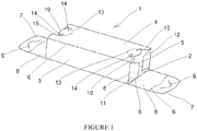
- FIGURE 1 a schematic perspective view of a packaging 1 in accordance with at least some embodiments of the present invention is illustrated.
- the packaging 1 comprises a first main panel 2, a first side panel 3, a second main panel 4, and a second side panel 5.
- the four adjoining panels define a box body and are separated from one another by folding lines 6 formed on a flexible material sheet.
- the packaging 1 further comprises two closure covers for said box body.
- the closure covers each include a tongue 7 projecting from a closure panel 8 in turn projecting from the first main panel 2.
- the closure panel 8 is separated from the tongue 7 and from the first main panel 2 by folding lines 6.
- a portion of the tongue 7 of each closure cover is configured to be introduced into the box body under the second main panel 4.
- the packaging 1 furthermore comprises a first dust panel 11 projecting from the first side panel 3 and a second dust panel 12 projecting from the second side panel 5.
- Each dust panel 11, 12 is provided for turning about a folding line 6 and is configured to be arranged under the closure panel 8 of the cover.
- the packaging 1 comprises a cut portion 9 wherein the cut extends through a portion of the tongue 7.
- a cut having a specific form is made through a portion of the tongue 7.
- two arrow tabs 10 are provided directly projecting from the second main panel 4.
- the second main panel 4 is arranged on the opposite side of the first main panel 2.
- the second main panel 4 comprises two preset breakage lines 13 for facilitating a separation of the arrow tabs 10 from the second main panel 4, respectively.
- the preset breakage lines 13 may be, for example, in the form of a portion of a circle.
- the arrow tabs 10 are each arranged in an indentation 15 of the second main panel 4. When the packaging is closed, at least a portion of an arrow tab 10 extends through the cut of the portion 9 and projects under the respective tongue 7.
- the arrow tabs 10 each comprise two undercuts 14 which are configured to be hooked in a portion of the respective tongue 7.
- the cuts of the cut portions 9 are formed such that the undercuts 14 of the arrow tabs 10 are configured to be hooked with the respective cut as the box is closed.
- the combination of the cut of the cut portion 9 and the hooked undercuts 14 prevent opening of each closure cover.
- the packaging 1 comprises only one closure cover on one side.
- the box body is permanently closed on the other side.
- the packaging 1 comprises two closure covers on opposite sides of the box body.
- FIGURE 2 a schematic perspective view of another packaging 1 in accordance with at least some embodiments of the present invention is illustrated.
- the arrow tabs 10 are each arranged in an indentation 15 of the second main panel 4.
- a portion of the tongue 7 is inserted under the second main panel 4.
- at least a portion of a respective arrow tab 10 extends through the cut of a portion 9 and projects under the respective tongue 7. Consequently, a second portion of the tongue 7 is arranged above the second main panel 4 as the box body is closed.
- the arrow tab 10 is formed such that it is easy to insert the arrow tab 10 through the cut of the cut portion 9.
- the second portion of the tongue 7 is configured to move out of the plane of the remaining portion of the tongue 7, thus providing an opening in the tongue 7, when the remaining portion of the tongue 7 is inserted under the second main panel 4.
- FIGURE 3 a schematic perspective view of a closed packaging 1 in accordance with at least some embodiments of the present invention is illustrated.
- Both closure covers are arranged in closed position.
- a portion of each tongue 7 is arranged under the second main panel 4.
- the undercuts of each arrow tab are hooked in a portion of the respective tongue 7.
- the combination of the cut of a cut portion 9 and the hooked undercuts 14 prevent opening of each closure cover.
- FIGURE 4 a schematic perspective view of a closed packaging 1 during opening of the packaging 1 in accordance with at least some embodiments of the present invention is illustrated.
- a closure cover of the packaging 1 it is necessary to break the respective preset breakage line 13. This can be e.g. easily done by breaking the breakage line 13 with a thumb or any other finger of a user.
- FIGURE 5 a schematic perspective view of an opened packaging 1 in accordance with at least some embodiments of the present invention is illustrated.
- the arrow tab 10 has been separated from the second main panel 4 by breaking the preset breakage line. Subsequently, the closure cover comprising the closure panel 8, the tongue 7, and the arrow tab 10 can be moved out of their fixed position. It is not possible to reconnect the arrow tab 10 to the main panel 4, and thus a tamper-evident packaging 1 is provided. A user can see by simple inspection of the packaging 1 that the packaging 1 has been previously opened.
- FIGURE 6 a schematic top view of a cut flexible material sheet 16 in accordance with at least some embodiments of the present invention is illustrated.
- the cut flexible material sheet 16 is designed for manufacturing a packaging according to any one of claims 1-8.
- the sheet 16 comprises a first main panel 2, a first side panel 3, a second main panel 4, a second side panel 5, and a clamping strip 17 projecting from the second main panel 4. Said panels 2, 3, 4, 5, and the clamping strip 17 are separated from one another by folding lines 6 formed on the flexible material sheet 16.
- the clamping strip 17 further comprises a glue area 19 for assembling the box body of the packaging.
- the sheet 16 furthermore comprises a tongue 7 projecting from a closure panel 8 in turn projecting from the first main panel 2.
- the closure panel 8 is separated from the tongue 7 and from the first main panel 2 by folding lines 6. Furthermore, the sheet 16 comprises a first dust panel 11 projecting from the first side panel 3 and a second dust panel 12 projecting from the second side panel 5. The first dust panel 11 is separated from the first side panel 3 by a folding line 6 and the second dust panel 12 is separated from the second side panel 5 by a folding line 6.
- a cut portion 9 is provided in a portion of the tongue 7. In other words, a cut is made through a portion of the tongue 7.
- an arrow tab 10 is provided projecting from the second main panel 4.
- the second main panel 4 comprises a preset breakage line 13 for facilitating a separation of the arrow tab 10 from the second main panel 4.
- the preset breakage line 13 may be, for example, in the form of a circle.
- the arrow tab 10 is arranged in an indentation 15 of the second main panel 4 and comprises two undercuts 14.
- the flexible material may be, for example, cardboard or any other material which can be punched or cut.
- the material has to be suitable for folding.
- the cut flexible material sheet 16 shown in FIGURE 6 is designed to provide two separate closure covers for the packaging.
- the above embodiments employ flexible materials for the packaging. Any material which allows for breakage of the panels along the breakage lines, as explained above, can be used.
- suitable materials include paperboard, which can be coated or uncoated, on one or both sides.
- the paperboard can be selected from a number of paperboard grades, for example from the group of folding box boards, white lined chipboards, greyboards, liquid packaging boards, solid bleached boards and coated unbleached boards and carrier boards.
- the grammage of the paperboard can vary for example in the range from about 50 to 750 g/m 2 , for example 60 to 350 g/m 2 .
- sheets of plastic materials as well as sheets of composite materials comprising both paperboard and plastic layers, can be used.
- At least some embodiments of the present invention find industrial application in tamper-evident packaging for healthcare products.
- the present packages can also be used for other products, such as foodstuff, confections and sweets, tobacco products, as well as electronics and other consumer goods which may be subject to counterfeiting.
Landscapes
- Engineering & Computer Science (AREA)
- Mechanical Engineering (AREA)
- Cartons (AREA)
Abstract
Description
- The present invention relates to a tamper-evident packaging. Further, the present invention relates to a cut flexible material sheet for a tamper-evident packaging.
- In certain applications, for example in packaging of healthcare products, tamper-evident packaging is required. In such applications the user can easily detect unauthorized or previous access to the protected object in order to make sure that the product has not been altered since it left the manufacturer.
- Many types of boxes are known provided with a security seal, the purpose of which is to make it evident by simple external examination that the initially closed box has already been opened for the first time, or to cause a portion of the box lid or a portion of the box itself to separate after initial opening, to prevent its reclosure.
- Such known boxes are typically formed from a single piece of punched and crease-lined cardboard or the like. Document
US 2009/0072018 A1 , for example, discloses a box formed from a single piece of punched and crease-lined cardboard sheet, the box having an inviolable security seal which is broken when the closed box is opened for the first time. The closed box presents a high resistance to deformation when subjected to external stresses. Additionally, documentWO 2015/170203 A1 describes a tamper-evident container comprising a storehouse defining an internal volume and exhibiting a predetermined number of lateral walls which define a passage opening delimited by a free edge, and a closure system engaged at the free edge and rotatingly movable with respect to the storehouse. The closure system is configured for defining a closed condition in which the system itself prevents the communication between the internal volume of the storehouse and the external environment. The closure system is further configured for defining an open condition in which the system itself enables the communication between the internal volume and the external environment. Further, the container comprises a safety device made of a sheet material comprising a removable portion configured for being separated from the safety device upon a first open condition of the closure system, following a first closed condition, for providing an evidence of a tampering of the container. - In view of the foregoing, it would be beneficial to provide a packaging which is more compact and for which less material is required for fabrication of the packaging.
- The invention is defined by the features of the independent claims. Some specific embodiments are defined in the dependent claims.
- According to a first aspect of the present invention, there is provided a packaging comprising a first main panel, a first side panel, a second main panel, and a second side panel defining a box body and being separated from one another by folding lines formed on a flexible material sheet, at least one closure cover for said box body, wherein the closure cover includes a tongue projecting from a closure panel in turn projecting from the first main panel, the closure panel being separated from the tongue and from the first main panel by folding lines, a portion of the tongue being configured to be introduced into the box body under the second main panel, a first dust panel projecting from the first side panel and a second dust panel projecting from the second side panel, wherein each dust panel is provided for turning about a folding line and is configured to be arranged under the closure panel of the cover, and wherein a cut portion is provided through a portion of the tongue, and an arrow tab is provided projecting from the second main panel, which is opposite to the first main panel the closure cover is connected to, and wherein the second main panel comprises a preset breakage line for facilitating a separation of the arrow tab.
- Various embodiments of the first aspect may comprise at least one feature from the following bulleted list:
- the preset breakage line is configured to break when the packaging is opened
- the arrow tab is arranged in an indentation of the second main panel
- at least a portion of the arrow tab extends through the cut portion and projects under the tongue as the box body is closed
- the arrow tab comprises two undercuts which are configured to be hooked in a portion of the tongue
- a portion of the tongue is configured to move out of the plane of the remaining portion of the tongue when the tongue is inserted under the second main panel
- the preset breakage line is in the form of a portion of a circle
- the packaging comprises two closure covers on opposite sides of the box body
- According to a second aspect of the present invention, there is provided a cut flexible material sheet for manufacturing a packaging according to any one of claims 1-8, wherein the sheet comprises a first main panel, a first side panel, a second main panel, and a second side panel, and a clamping strip projecting from one of said panels, said panels and the clamping strip being separated from one another by folding lines formed on the flexible material sheet, a tongue projecting from a closure panel in turn projecting from the first main panel, the closure panel being separated from the tongue and from the first main panel by folding lines, a first dust panel projecting from the first side panel and a second dust panel projecting from the second side panel, wherein the first dust panel is separated from the first side panel by a folding line and the second dust panel is separated from the second side panel by a folding line, and wherein a cut portion is provided through a portion of the tongue, and an arrow tab is provided projecting from the second main panel, and wherein the second main panel comprises a preset breakage line for facilitating a separation of the arrow tab.
- Various embodiments of the second aspect may comprise at least one feature from the following bulleted list:
- the arrow tab is arranged in an indentation of the second main panel
- the arrow tab comprises two undercuts
- the preset breakage line is in the form of a portion of a circle
- Considerable advantages are obtained by certain embodiments of the invention. A tamper-evident packaging is provided. Contrary to prior solutions, no additional panels or other material parts are arranged under the main panel within the box body. Instead, the arrow tab directly projects from one of the main panels and the respective cut is made directly through the tongue. Thus, the packaging according to certain embodiments of the present invention is more compact and less material is required for fabrication of the packaging. The blank, in the following also referred to as "cut flexible material sheet", can be further punched or cut from a flexible material sheet using high-speed machinery.
-
-
FIGURE 1 illustrates a schematic perspective view of a packaging in accordance with at least some embodiments of the present invention, -
FIGURE 2 illustrates a schematic perspective view of another packaging in accordance with at least some embodiments of the present invention, -
FIGURE 3 illustrates a schematic perspective view of a closed packaging in accordance with at least some embodiments of the present invention, -
FIGURE 4 illustrates a schematic perspective view of a closed packaging during opening of the packaging in accordance with at least some embodiments of the present invention, -
FIGURE 5 illustrates a schematic perspective view of an opened packaging in accordance with at least some embodiments of the present invention, and -
FIGURE 6 illustrates a schematic top view of a cut flexible material sheet in accordance with at least some embodiments of the present invention. - Certain embodiments of the present invention relate to a tamper-evident packaging. The packaging comprises an arrow tab which is formed as a portion of one of the main panels of a box body. In closed position, the arrow tab extends through a cut of a cut portion in a tongue of a closure cover and is hooked via two undercuts with the tongue. In order to open the packaging the arrow tab may be separated from said main panel by breaking a preset breakage line between said main panel and the arrow tab. Subsequently, the box cannot be re-closed as previously, thus providing a tamper-evident packaging, because a user can see by simple inspection of the packaging that the packaging has been previously opened.
- In
FIGURE 1 a schematic perspective view of apackaging 1 in accordance with at least some embodiments of the present invention is illustrated. Thepackaging 1 comprises a firstmain panel 2, afirst side panel 3, a secondmain panel 4, and asecond side panel 5. The four adjoining panels define a box body and are separated from one another by foldinglines 6 formed on a flexible material sheet. Thepackaging 1 further comprises two closure covers for said box body. The closure covers each include atongue 7 projecting from aclosure panel 8 in turn projecting from the firstmain panel 2. Theclosure panel 8 is separated from thetongue 7 and from the firstmain panel 2 byfolding lines 6. A portion of thetongue 7 of each closure cover is configured to be introduced into the box body under the secondmain panel 4. Thepackaging 1 furthermore comprises afirst dust panel 11 projecting from thefirst side panel 3 and asecond dust panel 12 projecting from thesecond side panel 5. Eachdust panel folding line 6 and is configured to be arranged under theclosure panel 8 of the cover. - Additionally, the
packaging 1 comprises acut portion 9 wherein the cut extends through a portion of thetongue 7. In other words, a cut having a specific form is made through a portion of thetongue 7. Further, twoarrow tabs 10 are provided directly projecting from the secondmain panel 4. The secondmain panel 4 is arranged on the opposite side of the firstmain panel 2. The secondmain panel 4 comprises twopreset breakage lines 13 for facilitating a separation of thearrow tabs 10 from the secondmain panel 4, respectively. Thepreset breakage lines 13 may be, for example, in the form of a portion of a circle. Thearrow tabs 10 are each arranged in anindentation 15 of the secondmain panel 4. When the packaging is closed, at least a portion of anarrow tab 10 extends through the cut of theportion 9 and projects under therespective tongue 7. - The
arrow tabs 10 each comprise twoundercuts 14 which are configured to be hooked in a portion of therespective tongue 7. In other words, the cuts of thecut portions 9 are formed such that theundercuts 14 of thearrow tabs 10 are configured to be hooked with the respective cut as the box is closed. The combination of the cut of thecut portion 9 and the hooked undercuts 14 prevent opening of each closure cover. - According to certain embodiments, the
packaging 1 comprises only one closure cover on one side. In this case the box body is permanently closed on the other side. According to certain other embodiments, thepackaging 1 comprises two closure covers on opposite sides of the box body. - In
FIGURE 2 a schematic perspective view of anotherpackaging 1 in accordance with at least some embodiments of the present invention is illustrated. As shown inFIGURE 1 , thearrow tabs 10 are each arranged in anindentation 15 of the secondmain panel 4. When the packaging is closed, a portion of thetongue 7 is inserted under the secondmain panel 4. Additionally, at least a portion of arespective arrow tab 10 extends through the cut of aportion 9 and projects under therespective tongue 7. Consequently, a second portion of thetongue 7 is arranged above the secondmain panel 4 as the box body is closed. Thearrow tab 10 is formed such that it is easy to insert thearrow tab 10 through the cut of thecut portion 9. In particular, because due to tension in the flexible material, the second portion of thetongue 7 is configured to move out of the plane of the remaining portion of thetongue 7, thus providing an opening in thetongue 7, when the remaining portion of thetongue 7 is inserted under the secondmain panel 4. - In
FIGURE 3 a schematic perspective view of aclosed packaging 1 in accordance with at least some embodiments of the present invention is illustrated. Both closure covers are arranged in closed position. In other words, a portion of eachtongue 7 is arranged under the secondmain panel 4. The undercuts of each arrow tab are hooked in a portion of therespective tongue 7. The combination of the cut of acut portion 9 and the hooked undercuts 14 prevent opening of each closure cover. For opening a closure cover of thepackaging 1 it is necessary to break the respectivepreset breakage line 13. - In
FIGURE 4 a schematic perspective view of aclosed packaging 1 during opening of thepackaging 1 in accordance with at least some embodiments of the present invention is illustrated. For opening a closure cover of thepackaging 1 it is necessary to break the respectivepreset breakage line 13. This can be e.g. easily done by breaking thebreakage line 13 with a thumb or any other finger of a user. - In
FIGURE 5 a schematic perspective view of an openedpackaging 1 in accordance with at least some embodiments of the present invention is illustrated. Thearrow tab 10 has been separated from the secondmain panel 4 by breaking the preset breakage line. Subsequently, the closure cover comprising theclosure panel 8, thetongue 7, and thearrow tab 10 can be moved out of their fixed position. It is not possible to reconnect thearrow tab 10 to themain panel 4, and thus a tamper-evident packaging 1 is provided. A user can see by simple inspection of thepackaging 1 that thepackaging 1 has been previously opened. - In
FIGURE 6 a schematic top view of a cutflexible material sheet 16 in accordance with at least some embodiments of the present invention is illustrated. The cutflexible material sheet 16 is designed for manufacturing a packaging according to any one of claims 1-8. Thesheet 16 comprises a firstmain panel 2, afirst side panel 3, a secondmain panel 4, asecond side panel 5, and aclamping strip 17 projecting from the secondmain panel 4. Saidpanels strip 17 are separated from one another by foldinglines 6 formed on theflexible material sheet 16. The clampingstrip 17 further comprises aglue area 19 for assembling the box body of the packaging. Thesheet 16 furthermore comprises atongue 7 projecting from aclosure panel 8 in turn projecting from the firstmain panel 2. Theclosure panel 8 is separated from thetongue 7 and from the firstmain panel 2 byfolding lines 6. Furthermore, thesheet 16 comprises afirst dust panel 11 projecting from thefirst side panel 3 and asecond dust panel 12 projecting from thesecond side panel 5. Thefirst dust panel 11 is separated from thefirst side panel 3 by afolding line 6 and thesecond dust panel 12 is separated from thesecond side panel 5 by afolding line 6. - A
cut portion 9 is provided in a portion of thetongue 7. In other words, a cut is made through a portion of thetongue 7. Additionally, anarrow tab 10 is provided projecting from the secondmain panel 4. The secondmain panel 4 comprises apreset breakage line 13 for facilitating a separation of thearrow tab 10 from the secondmain panel 4. Thepreset breakage line 13 may be, for example, in the form of a circle. Thearrow tab 10 is arranged in anindentation 15 of the secondmain panel 4 and comprises two undercuts 14. - The flexible material may be, for example, cardboard or any other material which can be punched or cut. The material has to be suitable for folding.
- The cut
flexible material sheet 16 shown inFIGURE 6 is designed to provide two separate closure covers for the packaging. - The above embodiments employ flexible materials for the packaging. Any material which allows for breakage of the panels along the breakage lines, as explained above, can be used. Typical examples of suitable materials include paperboard, which can be coated or uncoated, on one or both sides. The paperboard can be selected from a number of paperboard grades, for example from the group of folding box boards, white lined chipboards, greyboards, liquid packaging boards, solid bleached boards and coated unbleached boards and carrier boards. The grammage of the paperboard can vary for example in the range from about 50 to 750 g/m2, for example 60 to 350 g/m2. In addition to, or instead of, sheets of paperboard, sheets of plastic materials, as well as sheets of composite materials comprising both paperboard and plastic layers, can be used.
- It is to be understood that the embodiments of the invention disclosed are not limited to the particular structures, process steps, or materials disclosed herein, but are extended to equivalents thereof as would be recognized by those ordinarily skilled in the relevant arts. It should also be understood that terminology employed herein is used for the purpose of describing particular embodiments only and is not intended to be limiting.
- Reference throughout this specification to one embodiment or an embodiment means that a particular feature, structure, or characteristic described in connection with the embodiment is included in at least one embodiment of the present invention. Thus, appearances of the phrases "in one embodiment" or "in an embodiment" in various places throughout this specification are not necessarily all referring to the same embodiment. Where reference is made to a numerical value using a term such as, for example, about or substantially, the exact numerical value is also disclosed.
- As used herein, a plurality of items, structural elements, compositional elements, and/or materials may be presented in a common list for convenience. However, these lists should be construed as though each member of the list is individually identified as a separate and unique member. Thus, no individual member of such list should be construed as a de facto equivalent of any other member of the same list solely based on their presentation in a common group without indications to the contrary. In addition, various embodiments and example of the present invention may be referred to herein along with alternatives for the various components thereof. It is understood that such embodiments, examples, and alternatives are not to be construed as de facto equivalents of one another, but are to be considered as separate and autonomous representations of the present invention.
- Furthermore, the described features, structures, or characteristics may be combined in any suitable manner in one or more embodiments. In the following description, numerous specific details are provided, such as examples of lengths, widths, shapes, etc., to provide a thorough understanding of embodiments of the invention. One skilled in the relevant art will recognize, however, that the invention can be practiced without one or more of the specific details, or with other methods, components, materials, etc. In other instances, well-known structures, materials, or operations are not shown or described in detail to avoid obscuring aspects of the invention.
- While the forgoing examples are illustrative of the principles of the present invention in one or more particular applications, it will be apparent to those of ordinary skill in the art that numerous modifications in form, usage and details of implementation can be made without the exercise of inventive faculty, and without departing from the principles and concepts of the invention. Accordingly, it is not intended that the invention be limited, except as by the claims set forth below.
- The verbs "to comprise" and "to include" are used in this document as open limitations that neither exclude nor require the existence of also un-recited features. The features recited in depending claims are mutually freely combinable unless otherwise explicitly stated. Furthermore, it is to be understood that the use of "a" or "an", that is, a singular form, throughout this document does not exclude a plurality.
- At least some embodiments of the present invention find industrial application in tamper-evident packaging for healthcare products. The present packages can also be used for other products, such as foodstuff, confections and sweets, tobacco products, as well as electronics and other consumer goods which may be subject to counterfeiting.
-
- 1
- packaging
- 2
- first main panel
- 3
- first side panel
- 4
- second main panel
- 5
- second side panel
- 6
- folding line
- 7
- tongue
- 8
- closure panel
- 9
- cut portion
- 10
- arrow tab
- 11
- first dust panel
- 12
- second dust panel
- 13
- preset breakage line
- 14
- undercut
- 15
- indentation
- 16
- sheet
- 17
- clamping strip
- 18
- opening
- 19
- glue area
-
Claims (12)
- A packaging (1) comprising:- a first main panel (2), a first side panel (3), a second main panel (4), and a second side panel (5), defining a box body and being separated from one another by folding lines (6) formed on a flexible material sheet,- at least one closure cover for said box body, wherein the closure cover includes a tongue (7) projecting from a closure panel (8) in turn projecting from the first main panel (2), the closure panel (8) being separated from the tongue (7) and from the first main panel (2) by folding lines (6),- a portion of the tongue (7) being configured to be introduced into the box body under the second main panel (4), and- a first dust panel (11) projecting from the first side panel (3) and a second dust panel (12) projecting from the second side panel (5), wherein each dust panel (11, 12) is provided for turning about a folding line (6) and is configured to be arranged under the closure panel (8) of the cover,characterized by- a cut portion (9) provided in a portion of the tongue (7), and- an arrow tab (10) projecting from the second main panel (4), which is opposite to the first main panel (2), to which the closure cover is connected, and wherein the second main panel (4) comprises a preset breakage line (13) for facilitating a separation of the arrow tab (10).
- The packaging (1) according to claim 1, wherein the preset breakage line (13) is configured to break when the packaging (1) is opened.
- The packaging (1) according to claim 1 or 2, wherein the arrow tab (10) is arranged in an indentation (15) of the second main panel (4).
- The packaging (1) according to any one of claims 1-3, wherein at least a portion of the arrow tab (10) extends through the cut portion (9) and projects under the tongue (7) as the box body is closed.
- The packaging (1) according to claim 4, wherein the arrow tab (10) comprises two undercuts (14) which are configured to be hooked in a portion of the tongue (7).
- The packaging (1) according to any one of claims 1-5, wherein a portion of the tongue (7) is configured to move out of the plane of the remaining portion of the tongue (7) when the tongue (7) is inserted under the second main panel (4).
- The packaging (1) according to any one of claims 1-6, wherein the preset breakage line (13) is in the form of a portion of a circle.
- The packaging (1) according to any one of claims 1-7, wherein the packaging (1) comprises two closure covers on opposite sides of the box body.
- A cut flexible material sheet (16) for manufacturing a packaging according to any one of claims 1-8, wherein the sheet comprises:- a first main panel (2), a first side panel (3), a second main panel (4), and a second side panel (5), and a clamping strip (17) projecting from one of said panels (2, 3, 4, 5), said panels (2, 3, 4, 5) and the clamping strip (17) being separated from one another by folding lines (6) formed on the flexible material sheet (16),- a tongue (7) projecting from a closure panel (8) in turn projecting from the first main panel (2), the closure panel (8) being separated from the tongue (7) and from the first main panel (2) by folding lines (6), and- a first dust panel (11) projecting from the first side panel (3) and a second dust panel (12) projecting from the second side panel (5), wherein the first dust panel (11) is separated from the first side panel (3) by a folding line (6) and the second dust panel (12) is separated from the second side panel (5) by a folding line (6),characterized in that- a cut portion (9) is provided in a portion of the tongue (7), and- an arrow tab (10) is provided projecting from the second main panel (4), and wherein the second main panel (4) comprises a preset breakage line (13) for facilitating a separation of the arrow tab (10).
- The sheet (16) according to claim 9, wherein the arrow tab (10) is arranged in an indentation (15) of the second main panel (4).
- The sheet (16) according to claim 9 or 10, wherein the arrow tab (10) comprises two undercuts (14).
- The sheet (16) according to any one of claims 9-11, wherein the preset breakage line (13) is in the form of a portion of a circle.
Priority Applications (2)
| Application Number | Priority Date | Filing Date | Title |
|---|---|---|---|
| EP17172650.8A EP3406533A1 (en) | 2017-05-24 | 2017-05-24 | Tamper-evident packaging and flexible material sheet for such packaging |
| RU2017123764A RU2017123764A (en) | 2017-05-24 | 2017-07-05 | PACKING WITH OPENING TEST AND FLEXIBLE SHEET FOR SUCH PACKING |
Applications Claiming Priority (1)
| Application Number | Priority Date | Filing Date | Title |
|---|---|---|---|
| EP17172650.8A EP3406533A1 (en) | 2017-05-24 | 2017-05-24 | Tamper-evident packaging and flexible material sheet for such packaging |
Publications (1)
| Publication Number | Publication Date |
|---|---|
| EP3406533A1 true EP3406533A1 (en) | 2018-11-28 |
Family
ID=58772503
Family Applications (1)
| Application Number | Title | Priority Date | Filing Date |
|---|---|---|---|
| EP17172650.8A Withdrawn EP3406533A1 (en) | 2017-05-24 | 2017-05-24 | Tamper-evident packaging and flexible material sheet for such packaging |
Country Status (2)
| Country | Link |
|---|---|
| EP (1) | EP3406533A1 (en) |
| RU (1) | RU2017123764A (en) |
Cited By (1)
| Publication number | Priority date | Publication date | Assignee | Title |
|---|---|---|---|---|
| EP4617185A1 (en) | 2024-03-13 | 2025-09-17 | Atrilux | Tamper-evident package and manufacturing method |
Citations (5)
| Publication number | Priority date | Publication date | Assignee | Title |
|---|---|---|---|---|
| DE2846467A1 (en) * | 1978-10-25 | 1980-05-08 | Neckermann Versand Kgaa | Box with flip top and tuck-in tongue - having slit engaged by T=shaped snap-in lip on opposite side wall, unlocked by pressing lip cut=out |
| FR2504892A1 (en) * | 1981-04-30 | 1982-11-05 | Mars Alimentaire | Tamper resistant cardboard package - has tongue and slot closing lock necessitating partial destruction to obtain access to contents |
| DE8411183U1 (en) * | 1984-04-10 | 1984-06-07 | Dr. Karl Höhn GmbH Papier- und Kartonverarbeitungswerk, 7900 Ulm | Packaging in the form of a cardboard box |
| US20090072018A1 (en) | 2007-09-13 | 2009-03-19 | Gi.Bi.Effe S.R.I. | Box with inviolable security seal |
| WO2015170203A1 (en) | 2014-05-05 | 2015-11-12 | I.G.B. S.R.L. | Tamper evident container and process for making the same |
-
2017
- 2017-05-24 EP EP17172650.8A patent/EP3406533A1/en not_active Withdrawn
- 2017-07-05 RU RU2017123764A patent/RU2017123764A/en not_active Application Discontinuation
Patent Citations (5)
| Publication number | Priority date | Publication date | Assignee | Title |
|---|---|---|---|---|
| DE2846467A1 (en) * | 1978-10-25 | 1980-05-08 | Neckermann Versand Kgaa | Box with flip top and tuck-in tongue - having slit engaged by T=shaped snap-in lip on opposite side wall, unlocked by pressing lip cut=out |
| FR2504892A1 (en) * | 1981-04-30 | 1982-11-05 | Mars Alimentaire | Tamper resistant cardboard package - has tongue and slot closing lock necessitating partial destruction to obtain access to contents |
| DE8411183U1 (en) * | 1984-04-10 | 1984-06-07 | Dr. Karl Höhn GmbH Papier- und Kartonverarbeitungswerk, 7900 Ulm | Packaging in the form of a cardboard box |
| US20090072018A1 (en) | 2007-09-13 | 2009-03-19 | Gi.Bi.Effe S.R.I. | Box with inviolable security seal |
| WO2015170203A1 (en) | 2014-05-05 | 2015-11-12 | I.G.B. S.R.L. | Tamper evident container and process for making the same |
Cited By (2)
| Publication number | Priority date | Publication date | Assignee | Title |
|---|---|---|---|---|
| EP4617185A1 (en) | 2024-03-13 | 2025-09-17 | Atrilux | Tamper-evident package and manufacturing method |
| FR3160165A1 (en) | 2024-03-13 | 2025-09-19 | Atrilux | Packaging with tamper-evident device |
Also Published As
| Publication number | Publication date |
|---|---|
| RU2017123764A (en) | 2019-01-10 |
Similar Documents
| Publication | Publication Date | Title |
|---|---|---|
| US11225354B2 (en) | Tamper evident tuck end containers | |
| US11780654B2 (en) | Container with tearable lid | |
| EP4001148B1 (en) | Container and process of making the same | |
| US20220258907A1 (en) | Tamper evident carton | |
| EP2805895A1 (en) | Box having tamper-evident closure | |
| AU2015343451A1 (en) | Two-piece container lid | |
| EP3406533A1 (en) | Tamper-evident packaging and flexible material sheet for such packaging | |
| KR20170095838A (en) | Package including access opening with closure flap | |
| US20140260106A1 (en) | Wraparound case and method of making same | |
| WO2017032668A1 (en) | Container for consumer goods with sliding collar | |
| EP3441319A1 (en) | Tamper-evident packaging and flexible material sheet for such packaging | |
| US20200095013A1 (en) | Tamper evident tuck end containers | |
| US10081470B2 (en) | Reclosable packing case and method of making same | |
| US10023351B2 (en) | Box and package | |
| US20110192849A1 (en) | Break apart packaging for consumable products | |
| US12017826B2 (en) | Tamper-evident paperboard food container | |
| EP3626642B1 (en) | Tamper-proof packaging | |
| JP6522302B2 (en) | Packaging box | |
| EP2993142A1 (en) | Reclosable packing case and method of making same | |
| HK40017402A (en) | Tamper evident carton | |
| JP6122317B2 (en) | carton |
Legal Events
| Date | Code | Title | Description |
|---|---|---|---|
| PUAI | Public reference made under article 153(3) epc to a published international application that has entered the european phase |
Free format text: ORIGINAL CODE: 0009012 |
|
| STAA | Information on the status of an ep patent application or granted ep patent |
Free format text: STATUS: THE APPLICATION HAS BEEN PUBLISHED |
|
| AK | Designated contracting states |
Kind code of ref document: A1 Designated state(s): AL AT BE BG CH CY CZ DE DK EE ES FI FR GB GR HR HU IE IS IT LI LT LU LV MC MK MT NL NO PL PT RO RS SE SI SK SM TR |
|
| AX | Request for extension of the european patent |
Extension state: BA ME |
|
| STAA | Information on the status of an ep patent application or granted ep patent |
Free format text: STATUS: REQUEST FOR EXAMINATION WAS MADE |
|
| 17P | Request for examination filed |
Effective date: 20190321 |
|
| RBV | Designated contracting states (corrected) |
Designated state(s): AL AT BE BG CH CY CZ DE DK EE ES FI FR GB GR HR HU IE IS IT LI LT LU LV MC MK MT NL NO PL PT RO RS SE SI SK SM TR |
|
| STAA | Information on the status of an ep patent application or granted ep patent |
Free format text: STATUS: EXAMINATION IS IN PROGRESS |
|
| 17Q | First examination report despatched |
Effective date: 20190515 |
|
| STAA | Information on the status of an ep patent application or granted ep patent |
Free format text: STATUS: THE APPLICATION IS DEEMED TO BE WITHDRAWN |
|
| 18D | Application deemed to be withdrawn |
Effective date: 20200915 |