EP3406443A1 - Recoater cleaning system - Google Patents
Recoater cleaning system Download PDFInfo
- Publication number
- EP3406443A1 EP3406443A1 EP18173720.6A EP18173720A EP3406443A1 EP 3406443 A1 EP3406443 A1 EP 3406443A1 EP 18173720 A EP18173720 A EP 18173720A EP 3406443 A1 EP3406443 A1 EP 3406443A1
- Authority
- EP
- European Patent Office
- Prior art keywords
- recoater
- cleaning
- valve
- gas
- additive manufacturing
- Prior art date
- Legal status (The legal status is an assumption and is not a legal conclusion. Google has not performed a legal analysis and makes no representation as to the accuracy of the status listed.)
- Granted
Links
Images




Classifications
-
- B—PERFORMING OPERATIONS; TRANSPORTING
- B08—CLEANING
- B08B—CLEANING IN GENERAL; PREVENTION OF FOULING IN GENERAL
- B08B5/00—Cleaning by methods involving the use of air flow or gas flow
- B08B5/02—Cleaning by the force of jets, e.g. blowing-out cavities
-
- B—PERFORMING OPERATIONS; TRANSPORTING
- B29—WORKING OF PLASTICS; WORKING OF SUBSTANCES IN A PLASTIC STATE IN GENERAL
- B29C—SHAPING OR JOINING OF PLASTICS; SHAPING OF MATERIAL IN A PLASTIC STATE, NOT OTHERWISE PROVIDED FOR; AFTER-TREATMENT OF THE SHAPED PRODUCTS, e.g. REPAIRING
- B29C64/00—Additive manufacturing, i.e. manufacturing of three-dimensional [3D] objects by additive deposition, additive agglomeration or additive layering, e.g. by 3D printing, stereolithography or selective laser sintering
- B29C64/20—Apparatus for additive manufacturing; Details thereof or accessories therefor
- B29C64/205—Means for applying layers
- B29C64/218—Rollers
-
- B—PERFORMING OPERATIONS; TRANSPORTING
- B29—WORKING OF PLASTICS; WORKING OF SUBSTANCES IN A PLASTIC STATE IN GENERAL
- B29C—SHAPING OR JOINING OF PLASTICS; SHAPING OF MATERIAL IN A PLASTIC STATE, NOT OTHERWISE PROVIDED FOR; AFTER-TREATMENT OF THE SHAPED PRODUCTS, e.g. REPAIRING
- B29C64/00—Additive manufacturing, i.e. manufacturing of three-dimensional [3D] objects by additive deposition, additive agglomeration or additive layering, e.g. by 3D printing, stereolithography or selective laser sintering
- B29C64/30—Auxiliary operations or equipment
- B29C64/35—Cleaning
-
- B—PERFORMING OPERATIONS; TRANSPORTING
- B33—ADDITIVE MANUFACTURING TECHNOLOGY
- B33Y—ADDITIVE MANUFACTURING, i.e. MANUFACTURING OF THREE-DIMENSIONAL [3D] OBJECTS BY ADDITIVE DEPOSITION, ADDITIVE AGGLOMERATION OR ADDITIVE LAYERING, e.g. BY 3D PRINTING, STEREOLITHOGRAPHY OR SELECTIVE LASER SINTERING
- B33Y40/00—Auxiliary operations or equipment, e.g. for material handling
-
- B—PERFORMING OPERATIONS; TRANSPORTING
- B29—WORKING OF PLASTICS; WORKING OF SUBSTANCES IN A PLASTIC STATE IN GENERAL
- B29C—SHAPING OR JOINING OF PLASTICS; SHAPING OF MATERIAL IN A PLASTIC STATE, NOT OTHERWISE PROVIDED FOR; AFTER-TREATMENT OF THE SHAPED PRODUCTS, e.g. REPAIRING
- B29C64/00—Additive manufacturing, i.e. manufacturing of three-dimensional [3D] objects by additive deposition, additive agglomeration or additive layering, e.g. by 3D printing, stereolithography or selective laser sintering
- B29C64/30—Auxiliary operations or equipment
- B29C64/386—Data acquisition or data processing for additive manufacturing
- B29C64/393—Data acquisition or data processing for additive manufacturing for controlling or regulating additive manufacturing processes
-
- B—PERFORMING OPERATIONS; TRANSPORTING
- B29—WORKING OF PLASTICS; WORKING OF SUBSTANCES IN A PLASTIC STATE IN GENERAL
- B29K—INDEXING SCHEME ASSOCIATED WITH SUBCLASSES B29B, B29C OR B29D, RELATING TO MOULDING MATERIALS OR TO MATERIALS FOR MOULDS, REINFORCEMENTS, FILLERS OR PREFORMED PARTS, e.g. INSERTS
- B29K2105/00—Condition, form or state of moulded material or of the material to be shaped
- B29K2105/25—Solid
- B29K2105/251—Particles, powder or granules
-
- B—PERFORMING OPERATIONS; TRANSPORTING
- B33—ADDITIVE MANUFACTURING TECHNOLOGY
- B33Y—ADDITIVE MANUFACTURING, i.e. MANUFACTURING OF THREE-DIMENSIONAL [3D] OBJECTS BY ADDITIVE DEPOSITION, ADDITIVE AGGLOMERATION OR ADDITIVE LAYERING, e.g. BY 3D PRINTING, STEREOLITHOGRAPHY OR SELECTIVE LASER SINTERING
- B33Y30/00—Apparatus for additive manufacturing; Details thereof or accessories therefor
-
- B—PERFORMING OPERATIONS; TRANSPORTING
- B33—ADDITIVE MANUFACTURING TECHNOLOGY
- B33Y—ADDITIVE MANUFACTURING, i.e. MANUFACTURING OF THREE-DIMENSIONAL [3D] OBJECTS BY ADDITIVE DEPOSITION, ADDITIVE AGGLOMERATION OR ADDITIVE LAYERING, e.g. BY 3D PRINTING, STEREOLITHOGRAPHY OR SELECTIVE LASER SINTERING
- B33Y50/00—Data acquisition or data processing for additive manufacturing
- B33Y50/02—Data acquisition or data processing for additive manufacturing for controlling or regulating additive manufacturing processes
Definitions
- the present disclosure relates to additive manufacturing, more specifically to a system for cleaning a recoater (e.g., a roller type).
- a recoater e.g., a roller type
- the roller moves further left of the zero position and the bottom of the roller contacts a scraper to scrape off gunk that has built up on the roller. This system does not clean the top of the roller.
- a system for cleaning an additive manufacturing machine recoater includes a position module for sensing and/or determining a position of a recoater of the additive manufacturing machine and a gas manifold disposed in the additive manufacturing machine and configured to spray a pressurized gas on the recoater when the recoater is in at least one cleaning position.
- the system includes a valve configured to allow the pressurized gas to flow from a gas source to the gas manifold, and a valve control module configured to control the valve as a function of the position sensed and/or determined by the position module.
- the system can include a controller for controlling one or more components of the additive manufacturing machine, wherein the controller includes the valve control module.
- the controller can include the position module.
- the valve control module can be configured to open the valve when the recoater is at one or more selected positions.
- the one or more selected positions can include a cleaning position.
- the cleaning position can be behind a zero position of normal operation.
- the position module can include a position sensor configured to sense when the recoater is in a selected position.
- the gas manifold can include a pipe that extends in the direction of the recoater.
- the gas manifold can be positioned above the recoater within the additive manufacturing machine.
- the gas manifold can be positioned to spray gas in a direction away from one or both of a build area and a powder bed.
- a method comprises sensing and/or determining a position of a recoater of an additive manufacturing machine, determining whether the position of the recoater is one or more selected positions for cleaning, wherein if the position of the recoater is a selected position, opening a valve to allow a pressurized gas to flow through a cleaning manifold to spray on the recoater to clean the recoater.
- the one or more selected position can include beyond a zero position of normal operation of the recoater.
- the one or more selected position can be created and/or selected by a user.
- the method can include determining an interval of recoating, wherein if the interval of recoating is a selected interval of recoating, and if the position of the recoater is a selected position, opening a valve to allow a pressurized gas to flow through a cleaning manifold to spray on the recoater to clean the recoater.
- a non-transitory computer readable medium can include computer executable instruction for executing any suitable method and/or portion thereof as described herein.
- FIG. 1 an illustrative view of an embodiment of a system in accordance with the disclosure is shown in Fig. 1 and is designated generally by reference character 100.
- FIGs. 2A-3 Other embodiments and/or aspects of this disclosure are shown in Figs. 2A-3 .
- the systems and methods described herein can be used to improve additive manufacturing and/or reduce build failure, e.g., in powder fusion additive manufacturing machines.
- a system 100 for cleaning an additive manufacturing machine recoater 101 includes a position module 103 for sensing and/or determining a position of a recoater 101 of the additive manufacturing machine 105.
- the position module 103 can be embodied as and/or include any suitable hardware (e.g., a suitable position sensor, a microprocessor, or any other suitable circuitry) and/or software (e.g., any suitable software code of any suitable programming language) as appreciated by those having skill in the art.
- the position module 103 can include a sensor (e.g., an infrared sensor, a limiter switch) for sensing the position of the recoater 101 (e.g., such as a limiter switch for detecting when it has reached a selected position).
- the position module 103 can be a component of a controller 109 (described below) that can control the recoater 101 such that position of the recoater can be determined based on control inputs, timing, or any other suitable position determination.
- the system 100 further includes a gas manifold 107 disposed in the additive manufacturing machine and configured to spray a pressurized gas on the recoater 101 when the recoater 101 is in at least one cleaning position.
- the gas manifold 107 can be configured to be disposed in any suitable position in the additive manufacturing machine 105 and can include any suitable shape and outlets.
- the gas manifold can include a pipe 117 that extends in the direction of the recoater 101. As shown, the pipe 117 can includes a plurality of outlet holes 119.
- Embodiments of manifolds 107 can include a long channel and/or any other suitable shape. Embodiments can effuse gas at an angle to push gunk away from the feed stock (right to left in Fig. 1 ), but any other suitable configuration is contemplated herein.
- the gas manifold 107 can be positioned above the recoater 101 within the additive manufacturing machine 105.
- the gas manifold 107 can be positioned to spray gas in a direction away from one or both of a build area 121 and a powder bed 123. Any suitable number of gas manifolds 107 is contemplated herein.
- the system 100 includes a valve 109 configured to allow the pressurized gas to flow from a gas source 111 to the gas manifold 107.
- the gas source 111 can include any suitable type of gas (e.g., an inert gas such as argon or any other suitable gas).
- the valve 109 can include any suitable valve type and/or number of valves (e.g., a solenoid controlled valve).
- the system 100 can also include a valve control module 113 configured to control the valve 109 as a function of the position sensed and/or determined by the position module 103.
- the valve control module 113 can be embodied as and/or include any suitable hardware (e.g., a microprocessor or any other suitable circuitry) and/or software (e.g., any suitable software code of any suitable programming language) as appreciated by those having skill in the art. It is contemplated that the valve control module 109 and the position module 103 can be integrated together in a single hardware and/or software package in any suitable configuration.
- the valve control module 113 can be configured to open the valve 109 when the recoater 101 is at one or more selected positions.
- the one or more selected positions can include a cleaning position, however it is contemplated that the valve 109 can be configured to open at any suitable position of the recoater (e.g., manually by a user or automatically for any other suitable purpose).
- the valve control module 113 can control spray characteristics (e.g., spray length, spray direction and/or variance thereof, which of a plurality of manifolds is actuated at a particular moment) which can include any suitable characteristics and/or user defined.
- the system 100 can include a controller 115 for controlling one or more components of the additive manufacturing machine 105.
- the controller 115 can control the recoater 101 and/or any other suitable system(s) of the additive manufacturing machine 105.
- the controller 115 includes the valve control module 109 (e.g., as a hardware component and/or as a software component).
- the controller 115 can also include the position module 103 in certain embodiments (e.g., as a hardware component and/or as a software component).
- the cleaning position can be behind a zero position of normal operation.
- certain additive manufacturing machines are configured to cause a recoater 101 to move (e.g., as shown in Fig. 2A ) past a normal zero position of the recoater stroke (e.g., to the left of a zero position as shown in the orientation in Fig. 1 ) which can allow for a lower portion of the recoater 101 to be cleaned by a separate system.
- the position module 103 can send a signal to the valve control module 113 which can cause the valve 109 to be opened, thereby allowing other portions (e.g., the top) of the recoater 101 to be cleaned by gas from the manifold 107 (e.g., as shown in Figs. 2B and 2C ).
- the recoater 101 can be returned to normal operation (e.g., as shown in Fig. 2D ) to recoat the build area 121.
- the system 100 can be configured to be used with any suitable type of recoater 101.
- the recoater 101 can include a roller type recoater system as appreciated by those having skill in the art. Any other suitable type of recoater is contemplated herein.
- a method comprises sensing and/or determining a position of a recoater 101 of an additive manufacturing machine 105, determining whether the position of the recoater 101 is one or more selected positions for cleaning, wherein if the position of the recoater 101 is a selected position, opening a valve 109 to allow a pressurized gas to flow through a cleaning manifold 107 to spray on the recoater 101 to clean the recoater 101.
- the one or more selected position can include beyond a zero position of normal operation of the recoater.
- the method can include determining an interval of recoating, wherein if the interval of recoating is a selected interval of recoating, and if the position of the recoater 101 is a selected position, opening a valve 109 to allow a pressurized gas to flow through the cleaning manifold 107 to spray on the recoater 101 to clean the recoater 101.
- the system 100 can control how frequently the gas is used to clean the recoater 101 (e.g., once every 40 or 80 cycles).
- the selected position and/or cleaning position is not necessarily a physical position of the recoater 101, but can be a machine position, e.g., at a time t in cycle of recoating, the valve 109 can be opened.
- the one or more selected position can be created and/or selected by a user.
- Fig. 3 shows an embodiment of a method in accordance with this disclosure, however, any suitable embodiments of a method using any suitable embodiments of a system 100 as described above are contemplate herein.
- the recoating system engages a roller scraper every so often (e.g., 40 layers). During this sequence, the recoater roller moves to a negative position which scrapes roller of buildup.
- Embodiments of the system 100 can be designed to operate in conjunction with this operation and can perform as a "bolt-on" system.
- the position module can detect negative axis movement of recoater and triggers a valve solenoid to activate.
- a compressed inert gas can feed a distribution manifold, e.g., through side access ports.
- the gas manifold 107 then blows inert gas over recoater 101 removing excess powder/contaminants.
- the roller moves to negative position
- a sensor detects roller movement
- a control board reads input and actuates solenoid
- a solenoid opens valve, thereby releasing pressurized gas through cleaning manifold. Pressurized gas blows accumulated contaminant off the top of recoater to side of build chamber.
- the sensor detects position shift and the valve control module can close the solenoid and gas shuts off until the next interval. After 5 seconds, the roller returns to normal powder sequence in positive position.
- a non-transitory computer readable medium can include computer executable instruction for executing any suitable method and/or portion thereof as described hereinabove.
- aspects of the present disclosure may be embodied as a system, method or computer program product. Accordingly, aspects of the this disclosure may take the form of an entirely hardware embodiment, an entirely software embodiment (including firmware, resident software, micro-code, etc.) or an embodiment combining software and hardware aspects that may all generally be referred to herein as a "circuit,” “module” or “system.” Furthermore, aspects of the this disclosure may take the form of a computer program product embodied in one or more computer readable medium(s) having computer readable program code embodied thereon.
- the computer readable medium may be a computer readable signal medium or a computer readable storage medium.
- a computer readable storage medium may be, for example, but not limited to, an electronic, magnetic, optical, electromagnetic, infrared, or semiconductor system, apparatus, or device, or any suitable combination of the foregoing.
- a computer readable storage medium may be any tangible medium that can contain, or store a program for use by or in connection with an instruction execution system, apparatus, or device.
- a computer readable signal medium may include a propagated data signal with computer readable program code embodied therein, for example, in baseband or as part of a carrier wave. Such a propagated signal may take any of a variety of forms, including, but not limited to, electro-magnetic, optical, or any suitable combination thereof.
- a computer readable signal medium may be any computer readable medium that is not a computer readable storage medium and that can communicate, propagate, or transport a program for use by or in connection with an instruction execution system, apparatus, or device.
- Program code embodied on a computer readable medium may be transmitted using any appropriate medium, including but not limited to wireless, wireline, optical fiber cable, RF, etc., or any suitable combination of the foregoing.
- Computer program code for carrying out operations for aspects of the this disclosure may be written in any combination of one or more programming languages, including an object oriented programming language such as Java, Smalltalk, C++ or the like and conventional procedural programming languages, such as the "C" programming language or similar programming languages.
- the program code may execute entirely on the user's computer, partly on the user's computer, as a stand-alone software package, partly on the user's computer and partly on a remote computer or entirely on the remote computer or server.
- the remote computer may be connected to the user's computer through any type of network, including a local area network (LAN) or a wide area network (WAN), or the connection may be made to an external computer (for example, through the Internet using an Internet Service Provider).
- LAN local area network
- WAN wide area network
- Internet Service Provider for example, AT&T, MCI, Sprint, EarthLink, MSN, GTE, etc.
- These computer program instructions may also be stored in a computer readable medium that can direct a computer, other programmable data processing apparatus, or other devices to function in a particular manner, such that the instructions stored in the computer readable medium produce an article of manufacture including instructions which implement the function/act specified in the flowchart and/or block diagram block or blocks.
- the computer program instructions may also be loaded onto a computer, other programmable data processing apparatus, or other devices to cause a series of operational steps to be performed on the computer, other programmable apparatus or other devices to produce a computer implemented process such that the instructions which execute on the computer or other programmable apparatus provide processes for implementing the functions/acts specified herein.
- Embodiments prevent a current failure mode that is one of the most common causes of build failures in a powder bed fusion system.
- Embodiments include a mechanical and electrical system that may be integrated into a powder bed fusion system. Certain embodiments are configured for use with a roller recoater based system but can be configured for multiple blade and wiper recoating systems as well, or any other suitable system. Embodiments can be inserted into the build chamber at the negative x axis travel position of the recoating mechanism.
- embodiments Periodically throughout the build, in embodiments when the recoater travels to negative X position to scrape the roller, embodiments can engage a limit switch and activate a vacuum and inert gas pneumatic blast that will clear excess feedstock and contaminants from the recoater and push them into a benign area of the build chamber for later removal, and prevent this material from falling into the build area.
Landscapes
- Chemical & Material Sciences (AREA)
- Engineering & Computer Science (AREA)
- Materials Engineering (AREA)
- Manufacturing & Machinery (AREA)
- Physics & Mathematics (AREA)
- Mechanical Engineering (AREA)
- Optics & Photonics (AREA)
Abstract
Description
- The present disclosure relates to additive manufacturing, more specifically to a system for cleaning a recoater (e.g., a roller type).
- Many powder bed fusion systems have problems with contaminants generated during the PBF process. Some of these contaminants are the feedstock the system itself uses to grow parts. Excess or loose powder in the build area can fall into the fusion area, causing incomplete or improper fusion, resulting in failed builds. To reduce these contaminants in the vicinity of the build area, particulates are sprayed off the build area using pressurized inert gas during lasing, but this sprays particulates and off-gas onto the recoater, e.g., a roller recoater.
- In certain systems, after a certain intervals (e.g., every 40 or 80 layers of recoating), the roller moves further left of the zero position and the bottom of the roller contacts a scraper to scrape off gunk that has built up on the roller. This system does not clean the top of the roller.
- Such conventional methods and systems have generally been considered satisfactory for their intended purpose. However, there is still a need in the art for improved recoater cleaning systems. The present disclosure provides a solution for this need.
- In accordance with at least one aspect of this disclosure, a system for cleaning an additive manufacturing machine recoater includes a position module for sensing and/or determining a position of a recoater of the additive manufacturing machine and a gas manifold disposed in the additive manufacturing machine and configured to spray a pressurized gas on the recoater when the recoater is in at least one cleaning position. The system includes a valve configured to allow the pressurized gas to flow from a gas source to the gas manifold, and a valve control module configured to control the valve as a function of the position sensed and/or determined by the position module.
- The system can include a controller for controlling one or more components of the additive manufacturing machine, wherein the controller includes the valve control module. The controller can include the position module.
- The valve control module can be configured to open the valve when the recoater is at one or more selected positions. The one or more selected positions can include a cleaning position.
- The cleaning position can be behind a zero position of normal operation. The position module can include a position sensor configured to sense when the recoater is in a selected position.
- The gas manifold can include a pipe that extends in the direction of the recoater. The gas manifold can be positioned above the recoater within the additive manufacturing machine. The gas manifold can be positioned to spray gas in a direction away from one or both of a build area and a powder bed.
- In accordance with at least one aspect of this disclosure, a method comprises sensing and/or determining a position of a recoater of an additive manufacturing machine, determining whether the position of the recoater is one or more selected positions for cleaning, wherein if the position of the recoater is a selected position, opening a valve to allow a pressurized gas to flow through a cleaning manifold to spray on the recoater to clean the recoater. The one or more selected position can include beyond a zero position of normal operation of the recoater.
- The one or more selected position can be created and/or selected by a user. The method can include determining an interval of recoating, wherein if the interval of recoating is a selected interval of recoating, and if the position of the recoater is a selected position, opening a valve to allow a pressurized gas to flow through a cleaning manifold to spray on the recoater to clean the recoater.
- A non-transitory computer readable medium can include computer executable instruction for executing any suitable method and/or portion thereof as described herein.
- These and other features of the systems and methods of the subject disclosure will become more readily apparent to those skilled in the art from the following detailed description taken in conjunction with the drawings.
- So that those skilled in the art to which the subject disclosure appertains will readily understand how to make and use the devices and methods of the subject disclosure without undue experimentation, embodiments thereof will be described in detail herein below with reference to certain figures, wherein:
-
Fig. 1 is a perspective view of an embodiment of an additive manufacturing machine including an embodiment of a system in accordance with this disclosure; -
Fig. 2A is a schematic perspective view of an embodiment of a system in accordance with this disclosure, wherein a recoater is shown moving toward a cleaning position from a build area and/or powder bed area; -
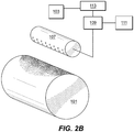
Fig. 2B is a schematic perspective view of the embodimentFig. 2A , wherein the recoater is shown in a cleaning position and the valve is closed; -
Fig. 2C is a schematic perspective view of the embodimentFig. 2A , wherein the recoater is shown in a cleaning position and the valve is open allowing gas to flow therethrough; -
Fig. 2D is a schematic perspective view of the embodimentFig. 2A , wherein the recoater is shown moving away from a cleaning position toward a powder bed area and/or a build area; and -
Fig. 3 is a flow diagram of an embodiment of a method in accordance with this disclosure. - Reference will now be made to the drawings wherein like reference numerals identify similar structural features or aspects of the subject disclosure. For purposes of explanation and illustration, and not limitation, an illustrative view of an embodiment of a system in accordance with the disclosure is shown in
Fig. 1 and is designated generally byreference character 100. Other embodiments and/or aspects of this disclosure are shown inFigs. 2A-3 . The systems and methods described herein can be used to improve additive manufacturing and/or reduce build failure, e.g., in powder fusion additive manufacturing machines. - In accordance with at least one aspect of this disclosure, referring to
Fig. 1 , asystem 100 for cleaning an additivemanufacturing machine recoater 101 includes aposition module 103 for sensing and/or determining a position of arecoater 101 of theadditive manufacturing machine 105. Theposition module 103 can be embodied as and/or include any suitable hardware (e.g., a suitable position sensor, a microprocessor, or any other suitable circuitry) and/or software (e.g., any suitable software code of any suitable programming language) as appreciated by those having skill in the art. - For example, in certain embodiments, the
position module 103 can include a sensor (e.g., an infrared sensor, a limiter switch) for sensing the position of the recoater 101 (e.g., such as a limiter switch for detecting when it has reached a selected position). In certain embodiments, theposition module 103 can be a component of a controller 109 (described below) that can control therecoater 101 such that position of the recoater can be determined based on control inputs, timing, or any other suitable position determination. - The
system 100 further includes agas manifold 107 disposed in the additive manufacturing machine and configured to spray a pressurized gas on therecoater 101 when therecoater 101 is in at least one cleaning position. Thegas manifold 107 can be configured to be disposed in any suitable position in theadditive manufacturing machine 105 and can include any suitable shape and outlets. For example, referring toFigs. 2A-2D , the gas manifold can include apipe 117 that extends in the direction of therecoater 101. As shown, thepipe 117 can includes a plurality ofoutlet holes 119. Embodiments ofmanifolds 107 can include a long channel and/or any other suitable shape. Embodiments can effuse gas at an angle to push gunk away from the feed stock (right to left inFig. 1 ), but any other suitable configuration is contemplated herein. - As shown, the
gas manifold 107 can be positioned above therecoater 101 within theadditive manufacturing machine 105. Thegas manifold 107 can be positioned to spray gas in a direction away from one or both of abuild area 121 and apowder bed 123. Any suitable number ofgas manifolds 107 is contemplated herein. - The
system 100 includes avalve 109 configured to allow the pressurized gas to flow from agas source 111 to thegas manifold 107. Thegas source 111 can include any suitable type of gas (e.g., an inert gas such as argon or any other suitable gas). Thevalve 109 can include any suitable valve type and/or number of valves (e.g., a solenoid controlled valve). - The
system 100 can also include avalve control module 113 configured to control thevalve 109 as a function of the position sensed and/or determined by theposition module 103. Thevalve control module 113 can be embodied as and/or include any suitable hardware (e.g., a microprocessor or any other suitable circuitry) and/or software (e.g., any suitable software code of any suitable programming language) as appreciated by those having skill in the art. It is contemplated that thevalve control module 109 and theposition module 103 can be integrated together in a single hardware and/or software package in any suitable configuration. - The
valve control module 113 can be configured to open thevalve 109 when therecoater 101 is at one or more selected positions. For example, the one or more selected positions can include a cleaning position, however it is contemplated that thevalve 109 can be configured to open at any suitable position of the recoater (e.g., manually by a user or automatically for any other suitable purpose). Thevalve control module 113 can control spray characteristics (e.g., spray length, spray direction and/or variance thereof, which of a plurality of manifolds is actuated at a particular moment) which can include any suitable characteristics and/or user defined. - The
system 100 can include acontroller 115 for controlling one or more components of theadditive manufacturing machine 105. Thecontroller 115 can control therecoater 101 and/or any other suitable system(s) of theadditive manufacturing machine 105. In certain embodiments, thecontroller 115 includes the valve control module 109 (e.g., as a hardware component and/or as a software component). Thecontroller 115 can also include theposition module 103 in certain embodiments (e.g., as a hardware component and/or as a software component). - In certain embodiments, the cleaning position can be behind a zero position of normal operation. For example, certain additive manufacturing machines are configured to cause a
recoater 101 to move (e.g., as shown inFig. 2A ) past a normal zero position of the recoater stroke (e.g., to the left of a zero position as shown in the orientation inFig. 1 ) which can allow for a lower portion of therecoater 101 to be cleaned by a separate system. While therecoater 101 is in such a position, or any other suitable position, theposition module 103 can send a signal to thevalve control module 113 which can cause thevalve 109 to be opened, thereby allowing other portions (e.g., the top) of therecoater 101 to be cleaned by gas from the manifold 107 (e.g., as shown inFigs. 2B and2C ). After cleaning, therecoater 101 can be returned to normal operation (e.g., as shown inFig. 2D ) to recoat thebuild area 121. - The
system 100 can be configured to be used with any suitable type ofrecoater 101. For example, therecoater 101 can include a roller type recoater system as appreciated by those having skill in the art. Any other suitable type of recoater is contemplated herein. - In accordance with at least one aspect of this disclosure, a method comprises sensing and/or determining a position of a
recoater 101 of anadditive manufacturing machine 105, determining whether the position of therecoater 101 is one or more selected positions for cleaning, wherein if the position of therecoater 101 is a selected position, opening avalve 109 to allow a pressurized gas to flow through acleaning manifold 107 to spray on therecoater 101 to clean therecoater 101. The one or more selected position can include beyond a zero position of normal operation of the recoater. - The method can include determining an interval of recoating, wherein if the interval of recoating is a selected interval of recoating, and if the position of the
recoater 101 is a selected position, opening avalve 109 to allow a pressurized gas to flow through thecleaning manifold 107 to spray on therecoater 101 to clean therecoater 101. This way, if one or more of the selected positions are in the normal stroke of therecoater 101, then thesystem 100 can control how frequently the gas is used to clean the recoater 101 (e.g., once every 40 or 80 cycles). - In certain embodiments, the selected position and/or cleaning position is not necessarily a physical position of the
recoater 101, but can be a machine position, e.g., at a time t in cycle of recoating, thevalve 109 can be opened. In certain embodiments, the one or more selected position can be created and/or selected by a user. -
Fig. 3 shows an embodiment of a method in accordance with this disclosure, however, any suitable embodiments of a method using any suitable embodiments of asystem 100 as described above are contemplate herein. In the embodiment ofFig. 3 , the recoating system engages a roller scraper every so often (e.g., 40 layers). During this sequence, the recoater roller moves to a negative position which scrapes roller of buildup. Embodiments of thesystem 100 can be designed to operate in conjunction with this operation and can perform as a "bolt-on" system. The position module can detect negative axis movement of recoater and triggers a valve solenoid to activate. Then, a compressed inert gas can feed a distribution manifold, e.g., through side access ports. Thegas manifold 107 then blows inert gas overrecoater 101 removing excess powder/contaminants. The roller moves to negative position - As shown in the embodiment of
Fig. 3 , a sensor detects roller movement, a control board reads input and actuates solenoid, and a solenoid opens valve, thereby releasing pressurized gas through cleaning manifold. Pressurized gas blows accumulated contaminant off the top of recoater to side of build chamber. When roller moves to positive, the sensor detects position shift and the valve control module can close the solenoid and gas shuts off until the next interval. After 5 seconds, the roller returns to normal powder sequence in positive position. - In accordance with at least one aspect of this disclosure, a non-transitory computer readable medium can include computer executable instruction for executing any suitable method and/or portion thereof as described hereinabove.
- As will be appreciated by those skilled in the art, aspects of the present disclosure may be embodied as a system, method or computer program product. Accordingly, aspects of the this disclosure may take the form of an entirely hardware embodiment, an entirely software embodiment (including firmware, resident software, micro-code, etc.) or an embodiment combining software and hardware aspects that may all generally be referred to herein as a "circuit," "module" or "system." Furthermore, aspects of the this disclosure may take the form of a computer program product embodied in one or more computer readable medium(s) having computer readable program code embodied thereon.
- Any combination of one or more computer readable medium(s) may be utilized. The computer readable medium may be a computer readable signal medium or a computer readable storage medium. A computer readable storage medium may be, for example, but not limited to, an electronic, magnetic, optical, electromagnetic, infrared, or semiconductor system, apparatus, or device, or any suitable combination of the foregoing. More specific examples (a non-exhaustive list) of the computer readable storage medium would include the following: an electrical connection having one or more wires, a portable computer diskette, a hard disk, a random access memory (RAM), a read-only memory (ROM), an erasable programmable read-only memory (EPROM or Flash memory), an optical fiber, a portable compact disc read-only memory (CD-ROM), an optical storage device, a magnetic storage device, or any suitable combination of the foregoing. In the context of this document, a computer readable storage medium may be any tangible medium that can contain, or store a program for use by or in connection with an instruction execution system, apparatus, or device.
- A computer readable signal medium may include a propagated data signal with computer readable program code embodied therein, for example, in baseband or as part of a carrier wave. Such a propagated signal may take any of a variety of forms, including, but not limited to, electro-magnetic, optical, or any suitable combination thereof. A computer readable signal medium may be any computer readable medium that is not a computer readable storage medium and that can communicate, propagate, or transport a program for use by or in connection with an instruction execution system, apparatus, or device.
- Program code embodied on a computer readable medium may be transmitted using any appropriate medium, including but not limited to wireless, wireline, optical fiber cable, RF, etc., or any suitable combination of the foregoing.
- Computer program code for carrying out operations for aspects of the this disclosure may be written in any combination of one or more programming languages, including an object oriented programming language such as Java, Smalltalk, C++ or the like and conventional procedural programming languages, such as the "C" programming language or similar programming languages. The program code may execute entirely on the user's computer, partly on the user's computer, as a stand-alone software package, partly on the user's computer and partly on a remote computer or entirely on the remote computer or server. In the latter scenario, the remote computer may be connected to the user's computer through any type of network, including a local area network (LAN) or a wide area network (WAN), or the connection may be made to an external computer (for example, through the Internet using an Internet Service Provider).
- Aspects of the this disclosure are described above with reference to flowchart illustrations and/or block diagrams of methods, apparatus (systems) and computer program products according to embodiments of the invention. It will be understood that each block of the flowchart illustrations and/or block diagrams, and combinations of blocks in the flowchart illustrations and/or block diagrams, can be implemented by computer program instructions. These computer program instructions may be provided to a processor of a general purpose computer, special purpose computer, or other programmable data processing apparatus to produce a machine, such that the instructions, which execute via the processor of the computer or other programmable data processing apparatus, create means for implementing the functions/acts specified in the flowchart and/or block diagram block or blocks.
- These computer program instructions may also be stored in a computer readable medium that can direct a computer, other programmable data processing apparatus, or other devices to function in a particular manner, such that the instructions stored in the computer readable medium produce an article of manufacture including instructions which implement the function/act specified in the flowchart and/or block diagram block or blocks.
- The computer program instructions may also be loaded onto a computer, other programmable data processing apparatus, or other devices to cause a series of operational steps to be performed on the computer, other programmable apparatus or other devices to produce a computer implemented process such that the instructions which execute on the computer or other programmable apparatus provide processes for implementing the functions/acts specified herein.
- As described above, embodiments prevent a current failure mode that is one of the most common causes of build failures in a powder bed fusion system. Embodiments include a mechanical and electrical system that may be integrated into a powder bed fusion system. Certain embodiments are configured for use with a roller recoater based system but can be configured for multiple blade and wiper recoating systems as well, or any other suitable system. Embodiments can be inserted into the build chamber at the negative x axis travel position of the recoating mechanism. Periodically throughout the build, in embodiments when the recoater travels to negative X position to scrape the roller, embodiments can engage a limit switch and activate a vacuum and inert gas pneumatic blast that will clear excess feedstock and contaminants from the recoater and push them into a benign area of the build chamber for later removal, and prevent this material from falling into the build area.
- The methods and systems of the present disclosure, as described above and shown in the drawings, provide for additive manufacturing machines with superior properties. While the apparatus and methods of the subject disclosure have been shown and described with reference to embodiments, those skilled in the art will readily appreciate that changes and/or modifications may be made thereto without departing from the scope of the subject disclosure.
Claims (15)
- A system for cleaning an additive manufacturing machine recoater, comprising:a position module for sensing and/or determining a position of a recoater of the additive manufacturing machine;a gas manifold disposed in the additive manufacturing machine and configured to spray a pressurized gas on the recoater when the recoater is in at least one cleaning position;a valve configured to allow the pressurized gas to flow from a gas source to the gas manifold; anda valve control module configured to control the valve as a function of the position sensed and/or determined by the position module.
- The system of claim 1, comprising a controller for controlling one or more components of the additive manufacturing machine, wherein the controller includes the valve control module.
- The system of claim 2, wherein the controller includes the position module.
- The system of claim 1, 2 or 3, wherein the valve control module is configured to open the valve when the recoater is at one or more selected positions.
- The system of claim 4, wherein the one or more selected positions include a cleaning position.
- The system of claim 5, wherein the cleaning position is behind a zero position of normal operation.
- The system of any preceding claim, wherein the position module includes a position sensor configured to sense when the recoater is in a selected position.
- The system of any preceding claim, wherein the gas manifold includes a pipe that extends in the direction of the recoater.
- The system of any preceding claim, wherein the gas manifold is positioned above or near the recoater within the additive manufacturing machine.
- The system of claim 9, wherein the gas manifold is positioned to spray gas in a direction away from one or both of a build area and a powder bed.
- A method, comprising:sensing and/or determining a position of a recoater of an additive manufacturing machine;determining whether the position of the recoater is one or more selected positions for cleaning;wherein if the position of the recoater is a selected position, opening a valve to allow a pressurized gas to flow through a cleaning manifold to spray on the recoater to clean the recoater.
- A non-transitory computer readable medium, comprising computer executable instruction for executing a method, the method including:sensing and/or determining a position of a recoater of an additive manufacturing machine;determining whether the position of the recoater is one or more selected positions for cleaning;wherein if the position of the recoater is a selected position, opening a valve to allow a pressurized gas to flow through a cleaning manifold to spray on the recoater to clean the recoater.
- The method of claim 11 or the non-transitory computer readable medium of claim 12, wherein the one or more selected position includes beyond a zero position of normal operation of the recoater.
- The method of claim 11 or 13, or the non-transitory computer readable medium of claim 12 or 13, wherein the one or more selected position can be created and/or selected by a user.
- The method of claim 11, 13 or 14, or the non-transitory computer readable medium of claim 12, 13 or 14, wherein the method further comprises determining an interval of recoating, wherein if the interval of recoating is a selected interval of recoating, and if the position of the recoater is a selected position, opening a valve to allow a pressurized gas to flow through a cleaning manifold to spray on the recoater to clean the recoater.
Applications Claiming Priority (1)
| Application Number | Priority Date | Filing Date | Title |
|---|---|---|---|
| US15/606,490 US10576510B2 (en) | 2017-05-26 | 2017-05-26 | Recoater cleaning system |
Publications (2)
| Publication Number | Publication Date |
|---|---|
| EP3406443A1 true EP3406443A1 (en) | 2018-11-28 |
| EP3406443B1 EP3406443B1 (en) | 2022-02-23 |
Family
ID=62245178
Family Applications (1)
| Application Number | Title | Priority Date | Filing Date |
|---|---|---|---|
| EP18173720.6A Active EP3406443B1 (en) | 2017-05-26 | 2018-05-23 | Recoater cleaning system |
Country Status (2)
| Country | Link |
|---|---|
| US (1) | US10576510B2 (en) |
| EP (1) | EP3406443B1 (en) |
Families Citing this family (22)
| Publication number | Priority date | Publication date | Assignee | Title |
|---|---|---|---|---|
| CN118848013A (en) | 2019-05-23 | 2024-10-29 | 通用电气公司 | Additive manufacturing equipment and methods |
| EP3972818A1 (en) | 2019-05-23 | 2022-03-30 | General Electric Company | Additive manufacturing recoat assemblies including sensors and methods for using the same |
| EP3972760A1 (en) | 2019-05-23 | 2022-03-30 | General Electric Company | Fluid management and circulation systems for use in additive manufacturing apparatuses |
| EP4245507A3 (en) | 2019-05-23 | 2023-12-20 | General Electric Company | Recoat assemblies for additive manufacturing systems and methods for using the same |
| WO2020237165A2 (en) | 2019-05-23 | 2020-11-26 | General Electric Company | Additive manufacturing apparatuses and methods for using the same |
| WO2020237123A2 (en) | 2019-05-23 | 2020-11-26 | General Electric Company | Cleaning fluids for use in additive manufacturing apparatuses and methods for monitoring status and performance of the same |
| US12233643B2 (en) | 2019-05-23 | 2025-02-25 | General Electric Company | Printing assemblies and methods for using the same |
| EP4272965A3 (en) | 2019-05-23 | 2023-12-20 | General Electric Company | Cleaning station and method of cleaning a print head |
| CN114126844A (en) | 2019-05-23 | 2022-03-01 | 通用电气公司 | Actuator assembly for additive manufacturing apparatus and method of using same |
| US12280596B2 (en) | 2019-05-23 | 2025-04-22 | General Electric Company | Cleaning systems for additive manufacturing apparatuses and methods for using the same |
| US12257778B2 (en) * | 2019-05-23 | 2025-03-25 | General Electric Company | Additive manufacturing recoat assemblies including a vacuum and methods for using the same |
| WO2021002277A1 (en) * | 2019-07-01 | 2021-01-07 | キヤノン株式会社 | Three-dimensional printing device and method of manufacturing three-dimensional printed object |
| JP7578810B2 (en) | 2020-10-20 | 2024-11-06 | ゼネラル・エレクトリック・カンパニイ | Print assembly and method for circulating binder material - Patents.com |
| JP7525738B2 (en) | 2020-10-20 | 2024-07-30 | ゼネラル・エレクトリック・カンパニイ | Method for forming an object and additive manufacturing system |
| EP4232265A1 (en) | 2020-10-21 | 2023-08-30 | General Electric Company | Material supply systems and methods for using the same |
| WO2022087048A1 (en) | 2020-10-21 | 2022-04-28 | General Electric Company | Material supply systems for additive manufacturing and methods for using the same |
| EP4232267A1 (en) | 2020-10-21 | 2023-08-30 | General Electric Company | Material supply system and method for using the same |
| US12533848B2 (en) | 2020-10-29 | 2026-01-27 | General Electric Company | Additive manufacturing apparatuses with removable build boxes and build box management systems |
| EP4237226A1 (en) | 2020-10-29 | 2023-09-06 | General Electric Company | Print head assembly and methods for using the same |
| WO2022093914A1 (en) | 2020-10-29 | 2022-05-05 | General Electric Company | Additive manufacturing apparatuses and methods for using the same |
| WO2022093943A1 (en) | 2020-10-29 | 2022-05-05 | General Electric Company | Additive manufacturing apparatuses with removable build boxes and lid management systems |
| DE102023122637A1 (en) * | 2023-08-23 | 2025-02-27 | Voxeljet Ag | Device for recoater cleaning, particulate material conditioning and its use in processes for the layer-by-layer construction of molded parts |
Citations (2)
| Publication number | Priority date | Publication date | Assignee | Title |
|---|---|---|---|---|
| DE102014010929A1 (en) * | 2014-07-28 | 2016-01-28 | Cl Schutzrechtsverwaltungs Gmbh | Device for producing three-dimensional objects |
| US20170072468A1 (en) * | 2014-05-14 | 2017-03-16 | Eos Gmbh Electro Optical Systems | Control Unit, Device and Method for the Production of a Three-Dimensional Object |
Family Cites Families (9)
| Publication number | Priority date | Publication date | Assignee | Title |
|---|---|---|---|---|
| DE202011101109U1 (en) | 2011-05-26 | 2012-08-28 | Weros Technology Gmbh | Inking unit of a printing press |
| US10994333B2 (en) | 2014-05-08 | 2021-05-04 | Stratasys Ltd. | Method and apparatus for 3D printing by selective sintering |
| DE102014007584A1 (en) * | 2014-05-26 | 2015-11-26 | Voxeljet Ag | 3D reverse printing method and apparatus |
| US9346127B2 (en) | 2014-06-20 | 2016-05-24 | Velo3D, Inc. | Apparatuses, systems and methods for three-dimensional printing |
| WO2016084351A1 (en) | 2014-11-28 | 2016-06-02 | Canon Kabushiki Kaisha | Method and apparatus for forming stereoscopic object |
| US9895724B2 (en) * | 2014-12-11 | 2018-02-20 | Toyota Motor Engineering & Manufacturing North America, Inc. | Pneumatic sweeping system |
| US10875093B2 (en) | 2015-07-17 | 2020-12-29 | Applied Materials, Inc. | Selective material dispensing in additive manufacturing |
| CN109070200A (en) * | 2016-03-03 | 2018-12-21 | 德仕托金属有限公司 | Additive Manufacturing Using Metal Build Materials |
| FR3058657B1 (en) * | 2016-11-14 | 2025-11-28 | Michelin & Cie | POWDER-BASED ADDITIVE MANUFACTURING PLANT WITH BLOWER CLEANING DEVICE |
-
2017
- 2017-05-26 US US15/606,490 patent/US10576510B2/en active Active
-
2018
- 2018-05-23 EP EP18173720.6A patent/EP3406443B1/en active Active
Patent Citations (2)
| Publication number | Priority date | Publication date | Assignee | Title |
|---|---|---|---|---|
| US20170072468A1 (en) * | 2014-05-14 | 2017-03-16 | Eos Gmbh Electro Optical Systems | Control Unit, Device and Method for the Production of a Three-Dimensional Object |
| DE102014010929A1 (en) * | 2014-07-28 | 2016-01-28 | Cl Schutzrechtsverwaltungs Gmbh | Device for producing three-dimensional objects |
Also Published As
| Publication number | Publication date |
|---|---|
| US10576510B2 (en) | 2020-03-03 |
| US20180339467A1 (en) | 2018-11-29 |
| EP3406443B1 (en) | 2022-02-23 |
Similar Documents
| Publication | Publication Date | Title |
|---|---|---|
| US10576510B2 (en) | Recoater cleaning system | |
| US10265790B2 (en) | Wire electric discharge machine having function of cleaning inside of machining tank | |
| US10699925B2 (en) | Transfer system | |
| US9782964B2 (en) | System and method for removing three-dimensional printed parts from a platen using inductive heating and gravity | |
| JP6364839B2 (en) | Work process management system and tag type individual controller used therefor | |
| US20170354997A1 (en) | Workpiece cleaning | |
| US20160379161A1 (en) | Material handling method | |
| CN108858184A (en) | Robot controller and computer-readable medium | |
| EP2268123A1 (en) | Method and device for the removal of a leaf from a crop | |
| US10289095B2 (en) | Wire electric discharge machining system | |
| JPWO2021177135A5 (en) | ||
| CN109791393B (en) | Method and apparatus for optimizing a target work line | |
| EP3406547B1 (en) | Filter monitoring in pneumatic transport systems | |
| CN108423427B (en) | Vacuum suction device and method | |
| JP2020085395A (en) | Automatic slag removal device and automatic slag removal program | |
| CN114837252B (en) | Automatic warehouse cleaning method, equipment and medium in cabin | |
| EP4641516A1 (en) | Systems and methods for annotating and tracking objects in a video | |
| KR102043554B1 (en) | Apparatus for removing fallen ore of continuous ship unloader | |
| CN203798653U (en) | Dyeing box transportation device and detection mechanism | |
| CN109109008B (en) | Processing method and device for manipulator falling | |
| JP2016044905A (en) | Incineration ash cooling system | |
| JP6206318B2 (en) | Conveyor transported object monitoring method and monitoring apparatus | |
| CN106315228B (en) | The automatic removal system of the blocking of filter stick conveying equipment | |
| WO2015033124A1 (en) | Pipeline cleaning device | |
| JP2008060463A (en) | Mounting machine, mounting line, and air blowing method for mounting machine |
Legal Events
| Date | Code | Title | Description |
|---|---|---|---|
| PUAI | Public reference made under article 153(3) epc to a published international application that has entered the european phase |
Free format text: ORIGINAL CODE: 0009012 |
|
| STAA | Information on the status of an ep patent application or granted ep patent |
Free format text: STATUS: THE APPLICATION HAS BEEN PUBLISHED |
|
| AK | Designated contracting states |
Kind code of ref document: A1 Designated state(s): AL AT BE BG CH CY CZ DE DK EE ES FI FR GB GR HR HU IE IS IT LI LT LU LV MC MK MT NL NO PL PT RO RS SE SI SK SM TR |
|
| AX | Request for extension of the european patent |
Extension state: BA ME |
|
| STAA | Information on the status of an ep patent application or granted ep patent |
Free format text: STATUS: REQUEST FOR EXAMINATION WAS MADE |
|
| 17P | Request for examination filed |
Effective date: 20190528 |
|
| RBV | Designated contracting states (corrected) |
Designated state(s): AL AT BE BG CH CY CZ DE DK EE ES FI FR GB GR HR HU IE IS IT LI LT LU LV MC MK MT NL NO PL PT RO RS SE SI SK SM TR |
|
| RIC1 | Information provided on ipc code assigned before grant |
Ipc: B29C 64/218 20170101ALI20210726BHEP Ipc: B29C 64/35 20170101ALI20210726BHEP Ipc: B08B 5/02 20060101ALI20210726BHEP Ipc: B33Y 40/00 20200101AFI20210726BHEP |
|
| GRAP | Despatch of communication of intention to grant a patent |
Free format text: ORIGINAL CODE: EPIDOSNIGR1 |
|
| STAA | Information on the status of an ep patent application or granted ep patent |
Free format text: STATUS: GRANT OF PATENT IS INTENDED |
|
| INTG | Intention to grant announced |
Effective date: 20210903 |
|
| GRAS | Grant fee paid |
Free format text: ORIGINAL CODE: EPIDOSNIGR3 |
|
| GRAA | (expected) grant |
Free format text: ORIGINAL CODE: 0009210 |
|
| STAA | Information on the status of an ep patent application or granted ep patent |
Free format text: STATUS: THE PATENT HAS BEEN GRANTED |
|
| AK | Designated contracting states |
Kind code of ref document: B1 Designated state(s): AL AT BE BG CH CY CZ DE DK EE ES FI FR GB GR HR HU IE IS IT LI LT LU LV MC MK MT NL NO PL PT RO RS SE SI SK SM TR |
|
| REG | Reference to a national code |
Ref country code: GB Ref legal event code: FG4D |
|
| REG | Reference to a national code |
Ref country code: CH Ref legal event code: EP |
|
| REG | Reference to a national code |
Ref country code: AT Ref legal event code: REF Ref document number: 1470146 Country of ref document: AT Kind code of ref document: T Effective date: 20220315 |
|
| REG | Reference to a national code |
Ref country code: IE Ref legal event code: FG4D |
|
| REG | Reference to a national code |
Ref country code: DE Ref legal event code: R096 Ref document number: 602018031109 Country of ref document: DE |
|
| RAP4 | Party data changed (patent owner data changed or rights of a patent transferred) |
Owner name: COLLINS ENGINE NOZZLES, INC. |
|
| REG | Reference to a national code |
Ref country code: LT Ref legal event code: MG9D |
|
| REG | Reference to a national code |
Ref country code: NL Ref legal event code: MP Effective date: 20220223 |
|
| REG | Reference to a national code |
Ref country code: AT Ref legal event code: MK05 Ref document number: 1470146 Country of ref document: AT Kind code of ref document: T Effective date: 20220223 |
|
| PG25 | Lapsed in a contracting state [announced via postgrant information from national office to epo] |
Ref country code: SE Free format text: LAPSE BECAUSE OF FAILURE TO SUBMIT A TRANSLATION OF THE DESCRIPTION OR TO PAY THE FEE WITHIN THE PRESCRIBED TIME-LIMIT Effective date: 20220223 Ref country code: RS Free format text: LAPSE BECAUSE OF FAILURE TO SUBMIT A TRANSLATION OF THE DESCRIPTION OR TO PAY THE FEE WITHIN THE PRESCRIBED TIME-LIMIT Effective date: 20220223 Ref country code: PT Free format text: LAPSE BECAUSE OF FAILURE TO SUBMIT A TRANSLATION OF THE DESCRIPTION OR TO PAY THE FEE WITHIN THE PRESCRIBED TIME-LIMIT Effective date: 20220623 Ref country code: NO Free format text: LAPSE BECAUSE OF FAILURE TO SUBMIT A TRANSLATION OF THE DESCRIPTION OR TO PAY THE FEE WITHIN THE PRESCRIBED TIME-LIMIT Effective date: 20220523 Ref country code: NL Free format text: LAPSE BECAUSE OF FAILURE TO SUBMIT A TRANSLATION OF THE DESCRIPTION OR TO PAY THE FEE WITHIN THE PRESCRIBED TIME-LIMIT Effective date: 20220223 Ref country code: LT Free format text: LAPSE BECAUSE OF FAILURE TO SUBMIT A TRANSLATION OF THE DESCRIPTION OR TO PAY THE FEE WITHIN THE PRESCRIBED TIME-LIMIT Effective date: 20220223 Ref country code: HR Free format text: LAPSE BECAUSE OF FAILURE TO SUBMIT A TRANSLATION OF THE DESCRIPTION OR TO PAY THE FEE WITHIN THE PRESCRIBED TIME-LIMIT Effective date: 20220223 Ref country code: ES Free format text: LAPSE BECAUSE OF FAILURE TO SUBMIT A TRANSLATION OF THE DESCRIPTION OR TO PAY THE FEE WITHIN THE PRESCRIBED TIME-LIMIT Effective date: 20220223 Ref country code: BG Free format text: LAPSE BECAUSE OF FAILURE TO SUBMIT A TRANSLATION OF THE DESCRIPTION OR TO PAY THE FEE WITHIN THE PRESCRIBED TIME-LIMIT Effective date: 20220523 |
|
| PG25 | Lapsed in a contracting state [announced via postgrant information from national office to epo] |
Ref country code: PL Free format text: LAPSE BECAUSE OF FAILURE TO SUBMIT A TRANSLATION OF THE DESCRIPTION OR TO PAY THE FEE WITHIN THE PRESCRIBED TIME-LIMIT Effective date: 20220223 Ref country code: LV Free format text: LAPSE BECAUSE OF FAILURE TO SUBMIT A TRANSLATION OF THE DESCRIPTION OR TO PAY THE FEE WITHIN THE PRESCRIBED TIME-LIMIT Effective date: 20220223 Ref country code: GR Free format text: LAPSE BECAUSE OF FAILURE TO SUBMIT A TRANSLATION OF THE DESCRIPTION OR TO PAY THE FEE WITHIN THE PRESCRIBED TIME-LIMIT Effective date: 20220524 Ref country code: FI Free format text: LAPSE BECAUSE OF FAILURE TO SUBMIT A TRANSLATION OF THE DESCRIPTION OR TO PAY THE FEE WITHIN THE PRESCRIBED TIME-LIMIT Effective date: 20220223 Ref country code: AT Free format text: LAPSE BECAUSE OF FAILURE TO SUBMIT A TRANSLATION OF THE DESCRIPTION OR TO PAY THE FEE WITHIN THE PRESCRIBED TIME-LIMIT Effective date: 20220223 |
|
| PG25 | Lapsed in a contracting state [announced via postgrant information from national office to epo] |
Ref country code: IS Free format text: LAPSE BECAUSE OF FAILURE TO SUBMIT A TRANSLATION OF THE DESCRIPTION OR TO PAY THE FEE WITHIN THE PRESCRIBED TIME-LIMIT Effective date: 20220623 |
|
| PG25 | Lapsed in a contracting state [announced via postgrant information from national office to epo] |
Ref country code: SM Free format text: LAPSE BECAUSE OF FAILURE TO SUBMIT A TRANSLATION OF THE DESCRIPTION OR TO PAY THE FEE WITHIN THE PRESCRIBED TIME-LIMIT Effective date: 20220223 Ref country code: SK Free format text: LAPSE BECAUSE OF FAILURE TO SUBMIT A TRANSLATION OF THE DESCRIPTION OR TO PAY THE FEE WITHIN THE PRESCRIBED TIME-LIMIT Effective date: 20220223 Ref country code: RO Free format text: LAPSE BECAUSE OF FAILURE TO SUBMIT A TRANSLATION OF THE DESCRIPTION OR TO PAY THE FEE WITHIN THE PRESCRIBED TIME-LIMIT Effective date: 20220223 Ref country code: EE Free format text: LAPSE BECAUSE OF FAILURE TO SUBMIT A TRANSLATION OF THE DESCRIPTION OR TO PAY THE FEE WITHIN THE PRESCRIBED TIME-LIMIT Effective date: 20220223 Ref country code: DK Free format text: LAPSE BECAUSE OF FAILURE TO SUBMIT A TRANSLATION OF THE DESCRIPTION OR TO PAY THE FEE WITHIN THE PRESCRIBED TIME-LIMIT Effective date: 20220223 Ref country code: CZ Free format text: LAPSE BECAUSE OF FAILURE TO SUBMIT A TRANSLATION OF THE DESCRIPTION OR TO PAY THE FEE WITHIN THE PRESCRIBED TIME-LIMIT Effective date: 20220223 |
|
| REG | Reference to a national code |
Ref country code: DE Ref legal event code: R097 Ref document number: 602018031109 Country of ref document: DE |
|
| PG25 | Lapsed in a contracting state [announced via postgrant information from national office to epo] |
Ref country code: AL Free format text: LAPSE BECAUSE OF FAILURE TO SUBMIT A TRANSLATION OF THE DESCRIPTION OR TO PAY THE FEE WITHIN THE PRESCRIBED TIME-LIMIT Effective date: 20220223 |
|
| PLBE | No opposition filed within time limit |
Free format text: ORIGINAL CODE: 0009261 |
|
| REG | Reference to a national code |
Ref country code: CH Ref legal event code: PL |
|
| STAA | Information on the status of an ep patent application or granted ep patent |
Free format text: STATUS: NO OPPOSITION FILED WITHIN TIME LIMIT |
|
| REG | Reference to a national code |
Ref country code: BE Ref legal event code: MM Effective date: 20220531 |
|
| PG25 | Lapsed in a contracting state [announced via postgrant information from national office to epo] |
Ref country code: MC Free format text: LAPSE BECAUSE OF FAILURE TO SUBMIT A TRANSLATION OF THE DESCRIPTION OR TO PAY THE FEE WITHIN THE PRESCRIBED TIME-LIMIT Effective date: 20220223 Ref country code: LU Free format text: LAPSE BECAUSE OF NON-PAYMENT OF DUE FEES Effective date: 20220523 Ref country code: LI Free format text: LAPSE BECAUSE OF NON-PAYMENT OF DUE FEES Effective date: 20220531 Ref country code: CH Free format text: LAPSE BECAUSE OF NON-PAYMENT OF DUE FEES Effective date: 20220531 |
|
| 26N | No opposition filed |
Effective date: 20221124 |
|
| PG25 | Lapsed in a contracting state [announced via postgrant information from national office to epo] |
Ref country code: SI Free format text: LAPSE BECAUSE OF FAILURE TO SUBMIT A TRANSLATION OF THE DESCRIPTION OR TO PAY THE FEE WITHIN THE PRESCRIBED TIME-LIMIT Effective date: 20220223 |
|
| PG25 | Lapsed in a contracting state [announced via postgrant information from national office to epo] |
Ref country code: IE Free format text: LAPSE BECAUSE OF NON-PAYMENT OF DUE FEES Effective date: 20220523 |
|
| PG25 | Lapsed in a contracting state [announced via postgrant information from national office to epo] |
Ref country code: BE Free format text: LAPSE BECAUSE OF NON-PAYMENT OF DUE FEES Effective date: 20220531 |
|
| P01 | Opt-out of the competence of the unified patent court (upc) registered |
Effective date: 20230530 |
|
| PG25 | Lapsed in a contracting state [announced via postgrant information from national office to epo] |
Ref country code: IT Free format text: LAPSE BECAUSE OF FAILURE TO SUBMIT A TRANSLATION OF THE DESCRIPTION OR TO PAY THE FEE WITHIN THE PRESCRIBED TIME-LIMIT Effective date: 20220223 |
|
| PG25 | Lapsed in a contracting state [announced via postgrant information from national office to epo] |
Ref country code: HU Free format text: LAPSE BECAUSE OF FAILURE TO SUBMIT A TRANSLATION OF THE DESCRIPTION OR TO PAY THE FEE WITHIN THE PRESCRIBED TIME-LIMIT; INVALID AB INITIO Effective date: 20180523 |
|
| PG25 | Lapsed in a contracting state [announced via postgrant information from national office to epo] |
Ref country code: MK Free format text: LAPSE BECAUSE OF FAILURE TO SUBMIT A TRANSLATION OF THE DESCRIPTION OR TO PAY THE FEE WITHIN THE PRESCRIBED TIME-LIMIT Effective date: 20220223 Ref country code: CY Free format text: LAPSE BECAUSE OF FAILURE TO SUBMIT A TRANSLATION OF THE DESCRIPTION OR TO PAY THE FEE WITHIN THE PRESCRIBED TIME-LIMIT Effective date: 20220223 |
|
| PG25 | Lapsed in a contracting state [announced via postgrant information from national office to epo] |
Ref country code: MT Free format text: LAPSE BECAUSE OF FAILURE TO SUBMIT A TRANSLATION OF THE DESCRIPTION OR TO PAY THE FEE WITHIN THE PRESCRIBED TIME-LIMIT Effective date: 20220223 |
|
| PG25 | Lapsed in a contracting state [announced via postgrant information from national office to epo] |
Ref country code: TR Free format text: LAPSE BECAUSE OF FAILURE TO SUBMIT A TRANSLATION OF THE DESCRIPTION OR TO PAY THE FEE WITHIN THE PRESCRIBED TIME-LIMIT Effective date: 20220223 |
|
| PGFP | Annual fee paid to national office [announced via postgrant information from national office to epo] |
Ref country code: GB Payment date: 20260421 Year of fee payment: 9 |
|
| PGFP | Annual fee paid to national office [announced via postgrant information from national office to epo] |
Ref country code: DE Payment date: 20260421 Year of fee payment: 9 |
|
| PGFP | Annual fee paid to national office [announced via postgrant information from national office to epo] |
Ref country code: FR Payment date: 20260421 Year of fee payment: 9 |