EP3406412A1 - Fiber-reinforced composite member molding device - Google Patents
Fiber-reinforced composite member molding device Download PDFInfo
- Publication number
- EP3406412A1 EP3406412A1 EP16886398.3A EP16886398A EP3406412A1 EP 3406412 A1 EP3406412 A1 EP 3406412A1 EP 16886398 A EP16886398 A EP 16886398A EP 3406412 A1 EP3406412 A1 EP 3406412A1
- Authority
- EP
- European Patent Office
- Prior art keywords
- molds
- design
- mold component
- reinforced composite
- design surface
- Prior art date
- Legal status (The legal status is an assumption and is not a legal conclusion. Google has not performed a legal analysis and makes no representation as to the accuracy of the status listed.)
- Granted
Links
Images



Classifications
-
- B—PERFORMING OPERATIONS; TRANSPORTING
- B29—WORKING OF PLASTICS; WORKING OF SUBSTANCES IN A PLASTIC STATE IN GENERAL
- B29C—SHAPING OR JOINING OF PLASTICS; SHAPING OF MATERIAL IN A PLASTIC STATE, NOT OTHERWISE PROVIDED FOR; AFTER-TREATMENT OF THE SHAPED PRODUCTS, e.g. REPAIRING
- B29C33/00—Moulds or cores; Details thereof or accessories therefor
- B29C33/02—Moulds or cores; Details thereof or accessories therefor with incorporated heating or cooling means
- B29C33/06—Moulds or cores; Details thereof or accessories therefor with incorporated heating or cooling means using radiation, e.g. electro-magnetic waves, induction heating
-
- B—PERFORMING OPERATIONS; TRANSPORTING
- B29—WORKING OF PLASTICS; WORKING OF SUBSTANCES IN A PLASTIC STATE IN GENERAL
- B29C—SHAPING OR JOINING OF PLASTICS; SHAPING OF MATERIAL IN A PLASTIC STATE, NOT OTHERWISE PROVIDED FOR; AFTER-TREATMENT OF THE SHAPED PRODUCTS, e.g. REPAIRING
- B29C33/00—Moulds or cores; Details thereof or accessories therefor
- B29C33/30—Mounting, exchanging or centering
- B29C33/301—Modular mould systems [MMS], i.e. moulds built up by stacking mould elements, e.g. plates, blocks, rods
- B29C33/302—Assembling a large number of mould elements to constitute one cavity
-
- B—PERFORMING OPERATIONS; TRANSPORTING
- B29—WORKING OF PLASTICS; WORKING OF SUBSTANCES IN A PLASTIC STATE IN GENERAL
- B29C—SHAPING OR JOINING OF PLASTICS; SHAPING OF MATERIAL IN A PLASTIC STATE, NOT OTHERWISE PROVIDED FOR; AFTER-TREATMENT OF THE SHAPED PRODUCTS, e.g. REPAIRING
- B29C33/00—Moulds or cores; Details thereof or accessories therefor
- B29C33/30—Mounting, exchanging or centering
- B29C33/306—Exchangeable mould parts, e.g. cassette moulds, mould inserts
-
- B—PERFORMING OPERATIONS; TRANSPORTING
- B29—WORKING OF PLASTICS; WORKING OF SUBSTANCES IN A PLASTIC STATE IN GENERAL
- B29C—SHAPING OR JOINING OF PLASTICS; SHAPING OF MATERIAL IN A PLASTIC STATE, NOT OTHERWISE PROVIDED FOR; AFTER-TREATMENT OF THE SHAPED PRODUCTS, e.g. REPAIRING
- B29C43/00—Compression moulding, i.e. applying external pressure to flow the moulding material; Apparatus therefor
- B29C43/32—Component parts, details or accessories; Auxiliary operations
- B29C43/52—Heating or cooling
-
- B—PERFORMING OPERATIONS; TRANSPORTING
- B29—WORKING OF PLASTICS; WORKING OF SUBSTANCES IN A PLASTIC STATE IN GENERAL
- B29C—SHAPING OR JOINING OF PLASTICS; SHAPING OF MATERIAL IN A PLASTIC STATE, NOT OTHERWISE PROVIDED FOR; AFTER-TREATMENT OF THE SHAPED PRODUCTS, e.g. REPAIRING
- B29C70/00—Shaping composites, i.e. plastics material comprising reinforcements, fillers or preformed parts, e.g. inserts
- B29C70/04—Shaping composites, i.e. plastics material comprising reinforcements, fillers or preformed parts, e.g. inserts comprising reinforcements only, e.g. self-reinforcing plastics
- B29C70/28—Shaping operations therefor
- B29C70/30—Shaping by lay-up, i.e. applying fibres, tape or broadsheet on a mould, former or core; Shaping by spray-up, i.e. spraying of fibres on a mould, former or core
- B29C70/34—Shaping by lay-up, i.e. applying fibres, tape or broadsheet on a mould, former or core; Shaping by spray-up, i.e. spraying of fibres on a mould, former or core and shaping or impregnating by compression, i.e. combined with compressing after the lay-up operation
- B29C70/345—Shaping by lay-up, i.e. applying fibres, tape or broadsheet on a mould, former or core; Shaping by spray-up, i.e. spraying of fibres on a mould, former or core and shaping or impregnating by compression, i.e. combined with compressing after the lay-up operation using matched moulds
-
- B—PERFORMING OPERATIONS; TRANSPORTING
- B29—WORKING OF PLASTICS; WORKING OF SUBSTANCES IN A PLASTIC STATE IN GENERAL
- B29C—SHAPING OR JOINING OF PLASTICS; SHAPING OF MATERIAL IN A PLASTIC STATE, NOT OTHERWISE PROVIDED FOR; AFTER-TREATMENT OF THE SHAPED PRODUCTS, e.g. REPAIRING
- B29C33/00—Moulds or cores; Details thereof or accessories therefor
- B29C33/02—Moulds or cores; Details thereof or accessories therefor with incorporated heating or cooling means
- B29C2033/023—Thermal insulation of moulds or mould parts
-
- B—PERFORMING OPERATIONS; TRANSPORTING
- B29—WORKING OF PLASTICS; WORKING OF SUBSTANCES IN A PLASTIC STATE IN GENERAL
- B29C—SHAPING OR JOINING OF PLASTICS; SHAPING OF MATERIAL IN A PLASTIC STATE, NOT OTHERWISE PROVIDED FOR; AFTER-TREATMENT OF THE SHAPED PRODUCTS, e.g. REPAIRING
- B29C35/00—Heating, cooling or curing, e.g. crosslinking or vulcanising; Apparatus therefor
- B29C35/02—Heating or curing, e.g. crosslinking or vulcanizing during moulding, e.g. in a mould
- B29C35/08—Heating or curing, e.g. crosslinking or vulcanizing during moulding, e.g. in a mould by wave energy or particle radiation
- B29C35/0805—Heating or curing, e.g. crosslinking or vulcanizing during moulding, e.g. in a mould by wave energy or particle radiation using electromagnetic radiation
- B29C2035/0811—Heating or curing, e.g. crosslinking or vulcanizing during moulding, e.g. in a mould by wave energy or particle radiation using electromagnetic radiation using induction
-
- B—PERFORMING OPERATIONS; TRANSPORTING
- B29—WORKING OF PLASTICS; WORKING OF SUBSTANCES IN A PLASTIC STATE IN GENERAL
- B29C—SHAPING OR JOINING OF PLASTICS; SHAPING OF MATERIAL IN A PLASTIC STATE, NOT OTHERWISE PROVIDED FOR; AFTER-TREATMENT OF THE SHAPED PRODUCTS, e.g. REPAIRING
- B29C35/00—Heating, cooling or curing, e.g. crosslinking or vulcanising; Apparatus therefor
- B29C35/16—Cooling
- B29C2035/1616—Cooling using liquids
-
- B—PERFORMING OPERATIONS; TRANSPORTING
- B29—WORKING OF PLASTICS; WORKING OF SUBSTANCES IN A PLASTIC STATE IN GENERAL
- B29C—SHAPING OR JOINING OF PLASTICS; SHAPING OF MATERIAL IN A PLASTIC STATE, NOT OTHERWISE PROVIDED FOR; AFTER-TREATMENT OF THE SHAPED PRODUCTS, e.g. REPAIRING
- B29C35/00—Heating, cooling or curing, e.g. crosslinking or vulcanising; Apparatus therefor
- B29C35/16—Cooling
- B29C2035/1658—Cooling using gas
-
- B—PERFORMING OPERATIONS; TRANSPORTING
- B29—WORKING OF PLASTICS; WORKING OF SUBSTANCES IN A PLASTIC STATE IN GENERAL
- B29C—SHAPING OR JOINING OF PLASTICS; SHAPING OF MATERIAL IN A PLASTIC STATE, NOT OTHERWISE PROVIDED FOR; AFTER-TREATMENT OF THE SHAPED PRODUCTS, e.g. REPAIRING
- B29C33/00—Moulds or cores; Details thereof or accessories therefor
- B29C33/02—Moulds or cores; Details thereof or accessories therefor with incorporated heating or cooling means
- B29C33/04—Moulds or cores; Details thereof or accessories therefor with incorporated heating or cooling means using liquids, gas or steam
-
- B—PERFORMING OPERATIONS; TRANSPORTING
- B29—WORKING OF PLASTICS; WORKING OF SUBSTANCES IN A PLASTIC STATE IN GENERAL
- B29C—SHAPING OR JOINING OF PLASTICS; SHAPING OF MATERIAL IN A PLASTIC STATE, NOT OTHERWISE PROVIDED FOR; AFTER-TREATMENT OF THE SHAPED PRODUCTS, e.g. REPAIRING
- B29C43/00—Compression moulding, i.e. applying external pressure to flow the moulding material; Apparatus therefor
- B29C43/32—Component parts, details or accessories; Auxiliary operations
- B29C43/36—Moulds for making articles of definite length, i.e. discrete articles
-
- B—PERFORMING OPERATIONS; TRANSPORTING
- B29—WORKING OF PLASTICS; WORKING OF SUBSTANCES IN A PLASTIC STATE IN GENERAL
- B29K—INDEXING SCHEME ASSOCIATED WITH SUBCLASSES B29B, B29C OR B29D, RELATING TO MOULDING MATERIALS OR TO MATERIALS FOR MOULDS, REINFORCEMENTS, FILLERS OR PREFORMED PARTS, e.g. INSERTS
- B29K2105/00—Condition, form or state of moulded material or of the material to be shaped
- B29K2105/06—Condition, form or state of moulded material or of the material to be shaped containing reinforcements, fillers or inserts
- B29K2105/08—Condition, form or state of moulded material or of the material to be shaped containing reinforcements, fillers or inserts of continuous length, e.g. cords, rovings, mats, fabrics, strands or yarns
- B29K2105/0872—Prepregs
-
- B—PERFORMING OPERATIONS; TRANSPORTING
- B29—WORKING OF PLASTICS; WORKING OF SUBSTANCES IN A PLASTIC STATE IN GENERAL
- B29L—INDEXING SCHEME ASSOCIATED WITH SUBCLASS B29C, RELATING TO PARTICULAR ARTICLES
- B29L2031/00—Other particular articles
- B29L2031/08—Blades for rotors, stators, fans, turbines or the like, e.g. screw propellers
-
- B—PERFORMING OPERATIONS; TRANSPORTING
- B29—WORKING OF PLASTICS; WORKING OF SUBSTANCES IN A PLASTIC STATE IN GENERAL
- B29L—INDEXING SCHEME ASSOCIATED WITH SUBCLASS B29C, RELATING TO PARTICULAR ARTICLES
- B29L2031/00—Other particular articles
- B29L2031/08—Blades for rotors, stators, fans, turbines or the like, e.g. screw propellers
- B29L2031/087—Propellers
Definitions
- the present disclosure relates to a fiber reinforced composite member molding apparatus used to mold a fiber reinforced composite member, such as a composite fan blade or a composite stator vane of a turbofan engine, from stacked sheets of prepreg formed of long carbon fibers impregnated with resin.
- thermoplastic CFRP member In molding a thermoplastic CFRP member from stacked sheets of prepreg formed of long carbon fibers impregnated with, for example thermoplastic resin as a matrix, a molding method using an autoclave is already established. Recently, as an alternative to the molding method using an autoclave, a mold hot press molding method using a molding apparatus is being developed.
- layered prepreg, or stacked sheets of prepreg are placed between a pair of molds in the molding apparatus, and heated to or above a melting temperature (curing temperature when the matrix resin is thermosetting resin) while pressure is applied to the layered prepreg with the thermoplastic resin melted, by the pair of molds.
- a melting temperature curing temperature when the matrix resin is thermosetting resin
- thermoplastic resin After the application of pressure, the thermoplastic resin is cooled via the pair of molds to a temperature at which the resulting molded article does not experience damage or deformation by opening of the molds.
- the fiber reinforced composite member with a desired shape is obtained this way.
- Patent Document 1 An example of conventional art molding apparatus intended for a pair of molds to produce a uniform temperature distribution in heating and cooling is disclosed in Patent Document 1.
- the disclosed molding apparatus includes a plurality of heaters individually associated with a plurality of regions constituting a design surface of each mold brought into contact with prepreg.
- each mold has cells open at the back of the design surface and individually corresponding to the regions of the design surface, and heaters are arranged in the cells, one for one.
- the heaters heat air supplied from an air source with their heating portions and blow the heated air to the back of the design surface of each mold, thereby heating the design surface.
- the heaters also function as coolers by blowing air to the back of the design surface of each mold with power supply to their heating portions stopped, thus without heating air.
- Patent Document 1 US 2012/0267828 A1
- the above-described conventional art molding apparatus is formed such that the pair of molds is heated by blowing air, heated by the heaters' heating portions, to the back of the design surface of each mold.
- the molds are not allowed to have a great thickness near the design surface, which makes it difficult for the molds to have sufficient rigidity.
- An object of the disclosure is to provide a fiber reinforced composite member molding apparatus which allows the molds to have sufficient rigidity and can produce a uniform temperature distribution not only in heating but also in cooling of the pair of molds.
- the present disclosure discloses a fiber reinforced composite member molding apparatus for molding a fiber reinforced composite member from stacked sheets of prepreg formed of long carbon fibers impregnated with resin, comprising a pair of molds provided to be brought nearer to or away from each other, heat sources to heat the resin contained in the prepreg via the molds in a clamped and pressed state with the stacked sheets of prereg clamped between the molds, and cooling passages to allow a cooling fluid to flow, thereby cooling the resin via the molds after heating of the resin contained in the prepreg, wherein the molds each have a design surface brought into contact with the stacked sheets of prereg, the design surface being divided into a plurality of regions, and a plurality of cells provided along the design surface to be open at the back of the design surface and individually correspond to the regions of the design surface, the heat sources are individually arranged in the cells, and the cooling passages are formed in each of the mold to run along the design surface.
- the fiber reinforced composite member molding apparatus has excellent effects, i.e., it allows the molds to have sufficient rigidity and can produce a uniform temperature distribution in heating and cooling of the pair of molds.
- FIGS. 1A to 9B show an embodiment of fiber reinforced composite member molding apparatus according to this disclosure.
- a fiber reinforced composite member to be molded is a composite fan blade FB of a turbofan engine with a blade tip FBt greatly twisted relative to a blade hub FBh. It is molded from a plurality of sheets of prepreg formed of long carbon fibers impregnated with resin, stacked such that sheets with differing fiber orientations form alternate layers.
- the fiber reinforced composite member molding apparatus 1 comprises a pair of molds 2, 3.
- the lower mold 2 comprises a base mold component 4 fixed onto a bolster B and a design mold component 6 detachably attached to the base mold component 4.
- the base mold component 4 of the lower mold for example tool steel (SCM440) is used, and for the design mold component 6 thereof, an alloy with a low thermal expansion rate, such as invar (registered trademark), is used.
- SCM440 tool steel
- invar registered trademark
- the upper mold 3 comprises a base mold component 5 fixed to a slide S moving up and down and a design mold component 7 detachably attached to the base mold component 5.
- the design mold component 7 clamps stacked sheets of prepreg, referred to as layered prepreg P (material to be molded into the composite fan blade FB), onto the design mold component 6 of the lower mold 2.
- the base mold component 5 of the upper mold for example tool steel (SCM440) is used, and for the design mold component 7 thereof, an alloy with a low thermal expansion rate, such as invar (registered trademark), is used.
- SCM440 tool steel
- invar registered trademark
- the molding apparatus 1 comprises induction heating coils (heat sources) 8 individually heating a plurality of regions of a design surface 61 of the design mold component 6 of the lower mold 2 brought into contact with the layered prepreg P.
- induction heating coils (heat sources) 8 individually heating a plurality of regions of a design surface 61 of the design mold component 6 of the lower mold 2 brought into contact with the layered prepreg P.
- the design mold component 6 of the lower mold 2 has a plurality of cells 62 provided along the design surface 61 to be open at the back of the design surface 61 and correspond to the regions of the design surface, and the induction heating coils 8 are arranged in the cells 62, one for one.
- the induction heating coils 62 arranged in the cells 62, one for one, are electrically connected to each other.
- the manner of arranging an induction heating coil 8 in each cell 62 is not limited to that shown in FIG. 3A , namely arranging the induction heating coil 8 to coil around an axis perpendicular to the design surface 61.
- the induction heating coil 8 may be arranged in the manner shown in FIG. 3B , namely arranged to coil around an axis running along the design surface 61. In place of the induction heating coils 8, cartridge heaters may be used as heat sources.
- the molding apparatus 1 further comprises a plurality of cooling passages 9 to allow a cooling fluid to flow to cool the layered prepreg P via the design mold component 6 of the lower mold 2.
- a cooling fluid a gas such as air or a liquid such as water can be used.
- the design mold component 6 of the lower mold 2 is formed by joining a plurality of design mold-constituting plates 63 abutting each other by diffusion bonding.
- the design mold-constituting plates 63 standing in the direction in which the molds 2, 3 are brought nearer to or away from each other, are diffusion-bonded in a vacuum by applying forces to bring them into close contact with each other at a melting temperature or below.
- the cooling passages 9 are each formed by cooling grooves 9a in adjacent design mold-constituting plates 63 meeting each other when the design mold-constituting plates 63 are diffusion-bonded.
- the cooling grooves 9a are formed in the design mold-constituting plates 63 in advance to run along the design surface 61.
- the distance d1 from the design surface 61 to each cooling passage 9 and the distance d2 from the cell 62 thereto are determined depending on the thickness of the layered prepreg P which differs from part to part. This means that the distance between the cooling passage 9 and the curved design surface 61 can be determined freely.
- the design mold component 6 can be cooled seamlessly, including the portions between the cells 62.
- the cooling fluid is supplied to the cooling passages 9 through vertical holes 64, which are formed by machining after the design mold component 6 is made by diffusion bonding.
- the design mold component 7 of the upper mold 3 comprises a plurality of cells provided along the design surface 71 to be open at the back of the design surface 71 and correspond to a plurality of regions of the design surface, and induction heating coils 8 are arranged in the cells, one for one.
- the design mold component 7 of the upper mold 3 is formed by joining a plurality of design mold-constituting plates by diffusion bonding, and cooling passages are formed between adjacent design mold-constituting plates to run along the design surface.
- thermoplastic resin contained in the layered prepreg P placed between the lower mold 2 and the upper mold 3 is heated to a melting temperature (curing temperature when the matrix resin is thermosetting resin) or above by the induction heating coils 8 arranged in the cells 62, one for one, and pressure is applied to the layered prereg P with the thermoplastic resin melted, by uniaxial pressing.
- thermoplastic resin After the application of pressure, by causing the cooling fluid to flow in the cooling passages 9 in the lower mold 2 and the upper mold 3, the thermoplastic resin is cooled to a temperature at which the resulting molded article does not experience damage or deformation by opening of the molds.
- the composite fan blade FB is obtained this way.
- the base mold component 4 and the design mold component 6 of the lower mold 2 in the molding apparatus 1 have a concave approximating opposing surface 46 and a convex approximating opposing surface 66, respectively.
- the approximating opposing surfaces are formed to approximate the design surface 61 of the design mold component 6 and adapted to be in contact with each other.
- the base mold component 4 and the design mold component 6 are connected together with a thermal insulator 10 (ceramic thermal insulator withstanding the molding pressure, for example) interposed between them by a connecting pin 11 running through their centers 46o, 66o of thermal expansion in heating of the thermoplastic resin contained in the layered prepreg P.
- the approximating opposing surfaces 46, 66 are composed of a plurality of polygonal planes 46a to 46f arranged around the center 46o and a plurality of polygonal planes 66a to 66f arranged around the center 66o, respectively.
- the approximating opposing surfaces 46, 66 of the base mold component 4 and the design mold component 6 are in contact with each other.
- the contact is maintained, because the approximating opposing surfaces 46, 66 are composed of the polygonal planes 46a to 46f arranged around the center 46o of thermal expansion and the polygonal planes 66a to 66f arranged around the center 66o of thermal expansion, respectively, which allows the polygonal planes 66a to 66f to be in sliding contact with the corresponding polygonal planes 46a to 46f.
- the connecting pin 11 for connecting the base mold component 4 and the design mold component 6 together is not indispensable, if the contact between the approximating opposing surfaces 46, 66 is satisfactorily and reliably maintained without it during heating and cooling.
- the base mold component 5 and the design mold component 7 of the upper mold 3 have a concave approximating opposing surface 56 and a convex approximating opposing surface 76, respectively.
- the approximating opposing surfaces are formed to approximate the design surface 71 of the design mold component 7 and adapted to be in contact with each other.
- the approximating opposing surfaces 56, 76 are composed of a plurality of polygonal planes 56a to 56f arranged around a center 56o of thermal expansion and a plurality of polygonal planes 76a to 76f arranged around a center 76o of thermal expansion in heating of the thermoplastic resin contained in the layered prepreg P, respectively.
- the base mold component 4 of the lower mold 2 in the molding apparatus 1 has dovetail grooves 41 open to the upper mold 3 side, which constitute a guide mechanism. As shown in FIG. 5A , the dovetail grooves 41 are arranged at four locations in a manner surrounding the approximating opposing surface 46.
- the base mold component 5 of the upper mold 3 in the molding apparatus 1 has dovetail tenons 51 projecting to the lower mold 2 side, which, in conjunction with the dovetail grooves 41, constitutes the guide mechanism. As shown in FIG. 7A , the dovetail tenons 51 are arranged at four locations in a manner surrounding the approximating opposing surface 56.
- the dovetail grooves 41 of the base mold component 4 of the lower mold 2 and the dovetail tenons 51 of the base mold component 5 of the upper mold 3 guide them smoothly by engaging with each other as shown in FIG. 8 .
- the dovetail grooves 41 and the dovetail tenons 51 constituting the guide mechanism are provided such that even when there is a difference in the amount of thermal expansion between the base mold component 4 of the lower mold 2 and the base mold component 5 of the upper mold 3, each dovetail groove 41 and the corresponding dovetail tenon 51 can engage in a varying positional relationship, maintaining the face contact between their side walls, as indicated by chain lines and two-dot chain lines in FIG.8 , thereby absorbing the difference in the amount of thermal expansion.
- a horizontal component H of resin pressure Pr acts on the hub FBh and the tip FBt in opposite directions, as shown in FIGS. 9A and 9B .
- a fixed point is set at a point which does not produce unbalance between the horizontal components H acting on the hub FBh and the tip FBt, and the centers 46o, 66o (56o, 76o) of thermal expansion are determined based on the fixed point.
- the design mold component 6 is connected to the base mold component 4 of the lower mold 2 by means of the connecting pin 11, wherein the approximating opposing surfaces 46, 66 of the base mold component 4 and the design mold component 6 of the lower mold 2 come into contact with each other, so that the design mold component 6 is stably attached to the base mold component 4.
- the design mold component 7 is connected to the base mold component 5 of the upper mold 3, wherein the approximating opposing surfaces 56, 76 of the base mold component 5 and the design mold component 7 of the upper mold 3 come into contact with each other, so that the design mold component 7 is stably attached to the base mold component 5.
- layered prepreg P, or stacked sheets of prepreg are set on the design mold component 6 of the lower mold 2 in a mold open state.
- the upper mold 3 is moved down with the slider S to bring the two molds into the clamped and pressed state, wherein the layered prepreg P is clamped between the design mold component 7 of the upper mold 3 and the design mold component 6 of the lower mold 2.
- the upper mold is guided smoothly by the dovetail tenons 51 of the base mold component 5 of the upper mold 3 engaging with the dovetail grooves 41 of the base mold component 4 of the lower mold 2.
- the design mold component 6 of the lower mold 2 produces a uniform temperature distribution in heating.
- the design mold component 7 of the upper mold 3 has induction heating coils 8 arranged in the same manner as in the lower mold 2, and thus, the design mold component 7 of the upper mold 3 produces a uniform temperature distribution in heating.
- the contact between the approximating opposing surfaces 46, 66 of the base mold component 4 and the design mold component 6 is maintained, because they are composed of the polygonal plane 46a to 46f arranged around the center 46o of thermal expansion and the polygonal plane 66a to 66f arranged around the center 66o of thermal expansion, respectively, which allows the polygonal planes 66a to 66f to be in sliding contact with the corresponding polygonal planes 46a to 46f. In other words, production of a space between the approximating opposing surfaces 46, 66 of the base mold component 4 and the design mold component 6 is avoided.
- the dovetail grooves 41 and the dovetail tenons 51 which constitute a guide mechanism, engage in a varying positional relationship, as indicated by chain lines and two-dot chain lines in FIG. 8 , thereby absorbing the difference in the amount of thermal expansion.
- the design mold component 6 of the lower mold 2 in heating, the design mold component 6 of the lower mold 2 produces a uniform temperature distribution, because the induction heating coils 8 are arranged in the cells 62 provided along the design surface 61 of the design mold component 6 of the lower mold 2 to be open at the back of the design surface 61, one for one (the same holds true for the upper mold 3).
- the induction heating coils 8 provided as heat sources directly heat the lower mold 2, which allows the design mold components 6, 7 of the molds 2, 3 to have an increased thickness near the design surfaces 61, 71 as compared with indirect heating in the conventional art, wherein the molds are heated by blowing air heated by heating portions of heaters to the back of the design surfaces of the molds, and thus, allows the design mold components 6, 7 to have an accordingly-increased, sufficient rigidity.
- the design mold component 6 of the lower mold 2 has cooling passages 9 running along the design surface 61. This makes it possible to cool the design mold component 6 not only at every point (cell 62) but also between points (between adjacent cells 62), thereby producing a uniform temperature distribution in cooling.
- the design mold component 6 of the lower mold 2 is formed by joining a plurality of design mold-constituting plates 63 abutting each other by diffusion bonding, wherein the cooling passages 9 in the design mold component 6 are each formed by cooling grooves 9a in adjacent design mold-constituting plates 63 meeting each other.
- the cooling grooves 9a are formed in the design mold-constituting plates 63 in advance to run along the design surface 61. This makes it possible to give a constant distance between the cooling passage 9 and the design surface 61 or vary the distance between them depending on the thickness of the layered prepreg P which varies from part to part. This also makes it possible to construct a three-dimensional cooling circuit.
- the embodiment has been described based on an example in which the fiber reinforced composite member molding apparatus according to this disclosure is adapted to mold a composite fan blade FB of a turbofan engine having a great angle of twist.
- the fiber reinforced composite member molding apparatus according to this disclosure is however not limited to this example.
- the fiber reinforced composite member molding apparatus can be adapted to mold a composite stator vane of a turbofan engine, wherein a pair of molds each comprise a base mold component 4A and a design mold component 6A as partially shown in FIG. 10 , wherein the base mold component 4A and the design mold component 6A have approximating opposing surfaces formed to approximate a design surface 61A and composed of rectangular planes 46A, 46B arranged to opposite sides of a centerline 460 of thermal expansion and abutting each other and rectangular planes 66A, 66B arranged to opposite sides of a centerline 660 of thermal expansion and abutting each other, respectively.
- resins usable as a matrix to form prepreg include thermoplastic resins such as PEEK (polyether ether ketone resin), PEI (polyetherimide resin) and PIXA (thermoplastic polyimide resin), and thermosetting resins such as epoxy resin, phenol resin and polyimide resin.
- thermoplastic resins such as PEEK (polyether ether ketone resin), PEI (polyetherimide resin) and PIXA (thermoplastic polyimide resin)
- thermosetting resins such as epoxy resin, phenol resin and polyimide resin.
- a first aspect according to this disclosure is a fiber reinforced composite member molding apparatus for molding a fiber reinforced composite member from stacked sheets of prepreg formed of long carbon fibers impregnated with resin, comprising a pair of molds provided to be brought nearer to or away from each other, heat sources to heat the resin contained in the prepreg via the molds in a clamped and pressed state with the stacked sheets of prereg clamped between the molds, and cooling passages to allow a cooling fluid to flow, thereby cooling the resin via the molds after heating of the resin contained in the prepreg, wherein the molds each have a design surface brought into contact with the stacked sheets of prereg, the design surface being divided into a plurality of regions, and a plurality of cells provided along the design surface to be open at the back of the design surface and individually correspond to the regions of the design surface, the heat sources are individually arranged in the cells, and the cooling passages are formed in each of the molds to run along the design surface.
- heat sources are arranged in the cells provided along the design surface of each of the molds to be open at the back of the design surface, one for one, and cooling passages are provided to run along the design surface of each of the molds. This makes it possible to produce a uniform temperature distribution in heating and cooling of the molds.
- the molds are heated directly by the heat sources, which allows the molds to have an increased thickness near the design surface as compared with indirect heating in the conventional art, wherein the molds are heated by blowing air heated by heating portions of heaters to the back of the design surface of each mold, and thus, allow the molds to have an accordingly-increased, sufficient rigidity.
- the molds each comprise a base mold component and a design mold component providing the design surface and detachably attached to the base mold component with a thermal insulator interposed therebetween
- the design mold component of each of the molds is formed by joining a plurality of design mold-constituting plates, arranged to abut each other in a position standing in the direction in which the molds are brought nearer to or away from each other, by diffusion bonding
- the design mold-constituting plates have cooling grooves provided such that the cooling grooves in adjacent design mold-constituting plates meet each other to form the cooling passages.
- the cooling passages are formed by cooling grooves in adjacent design mold-constituting plates meeting each other, wherein the cooling grooves are formed in the design mold-constituting plates in advance to run along the design surface.
- the base mold component and the design mold component of each of the molds have approximating opposing surfaces formed to approximate the design surface, the approximating opposing surfaces of the base mold component and the design mold component each comprising a plurality of polygonal planes arranged around a center of thermal expansion in heating of the resin contained in the prepreg and abutting each other.
- the approximating opposing surfaces of the base mold component and the design mold component of each of the molds which are in contact with each other during cooling, maintain the contact even if only the design mold component experiences thermal expansion during heating, because the polygonal planes of the design mold component arranged around the center of thermal expansion are in sliding contact with the corresponding polygonal planes of the base mold component.
- the base mold component and the design mold component are connected together by a connecting member running through their centers of thermal expansion.
- the contact between the approximating opposing surfaces of the base mold component and the design mold component is maintained satisfactorily and reliably in heating and cooling.
- the base mold components of the molds have a guide mechanism for guiding the molds in movement relative to each other and absorbing a difference in the amount of thermal expansion between the molds.
- the guide mechanism when the molds are brought into the clamped state, the guide mechanism smoothly guides the molds, and when there is a difference in the amount of thermal expansion between the molds, the guide mechanism absorbs the difference in the amount of thermal expansion.
- the base mold component and the design mold component of each of the molds have approximating opposing surfaces formed to approximate the design surface, the approximating opposing surfaces of the base mold component and the design mold component each comprising a plurality of rectangular planes arranged to opposite sides of a centerline of thermal expansion in heating of the resin contained in the prepreg and abutting each other.
- the approximating opposing surfaces of the base mold component and the design mold component of each of the molds which are in contact with each other during cooling, maintain the contact even if only the design mold component experiences thermal expansion during heating, because the rectangular planes of the design mold component arranged to the opposite sides of the centerline of thermal expansion are in sliding contact with the corresponding rectangular planes of the base mold component.
Landscapes
- Engineering & Computer Science (AREA)
- Mechanical Engineering (AREA)
- Health & Medical Sciences (AREA)
- Toxicology (AREA)
- Chemical & Material Sciences (AREA)
- Composite Materials (AREA)
- Moulds For Moulding Plastics Or The Like (AREA)
- Moulding By Coating Moulds (AREA)
- Casting Or Compression Moulding Of Plastics Or The Like (AREA)
Abstract
Description
- The present disclosure relates to a fiber reinforced composite member molding apparatus used to mold a fiber reinforced composite member, such as a composite fan blade or a composite stator vane of a turbofan engine, from stacked sheets of prepreg formed of long carbon fibers impregnated with resin.
- In molding a thermoplastic CFRP member from stacked sheets of prepreg formed of long carbon fibers impregnated with, for example thermoplastic resin as a matrix, a molding method using an autoclave is already established. Recently, as an alternative to the molding method using an autoclave, a mold hot press molding method using a molding apparatus is being developed.
- When molding a fiber reinforced composite member using the mold hot press molding method, layered prepreg, or stacked sheets of prepreg are placed between a pair of molds in the molding apparatus, and heated to or above a melting temperature (curing temperature when the matrix resin is thermosetting resin) while pressure is applied to the layered prepreg with the thermoplastic resin melted, by the pair of molds.
- After the application of pressure, the thermoplastic resin is cooled via the pair of molds to a temperature at which the resulting molded article does not experience damage or deformation by opening of the molds. The fiber reinforced composite member with a desired shape is obtained this way.
- In the mold hot press molding method, whether the fiber reinforced composite member exhibits the strength of the material is greatly affected by the molding temperature. It is therefore required to control the pair of molds to produce a uniform temperature distribution.
- An example of conventional art molding apparatus intended for a pair of molds to produce a uniform temperature distribution in heating and cooling is disclosed in Patent Document 1. The disclosed molding apparatus includes a plurality of heaters individually associated with a plurality of regions constituting a design surface of each mold brought into contact with prepreg.
- In this example, each mold has cells open at the back of the design surface and individually corresponding to the regions of the design surface, and heaters are arranged in the cells, one for one.
- The heaters heat air supplied from an air source with their heating portions and blow the heated air to the back of the design surface of each mold, thereby heating the design surface. The heaters also function as coolers by blowing air to the back of the design surface of each mold with power supply to their heating portions stopped, thus without heating air.
- Patent Document 1:
US 2012/0267828 A1 - The above-described conventional art molding apparatus is formed such that the pair of molds is heated by blowing air, heated by the heaters' heating portions, to the back of the design surface of each mold. Thus, in order to produce a uniform temperature distribution over the design surface, the molds are not allowed to have a great thickness near the design surface, which makes it difficult for the molds to have sufficient rigidity.
- Further, since the pair of molds is cooled by blowing air to the back of the design surface within each cell, the molds are hard to cool between the adjacent cells, resulting in a temperature difference from the centers of the cells. The solutions to these problems have been being sought for.
- This disclosure is presented in view of the above problems with the conventional art. An object of the disclosure is to provide a fiber reinforced composite member molding apparatus which allows the molds to have sufficient rigidity and can produce a uniform temperature distribution not only in heating but also in cooling of the pair of molds.
- The present disclosure discloses a fiber reinforced composite member molding apparatus for molding a fiber reinforced composite member from stacked sheets of prepreg formed of long carbon fibers impregnated with resin, comprising a pair of molds provided to be brought nearer to or away from each other, heat sources to heat the resin contained in the prepreg via the molds in a clamped and pressed state with the stacked sheets of prereg clamped between the molds, and cooling passages to allow a cooling fluid to flow, thereby cooling the resin via the molds after heating of the resin contained in the prepreg, wherein the molds each have a design surface brought into contact with the stacked sheets of prereg, the design surface being divided into a plurality of regions, and a plurality of cells provided along the design surface to be open at the back of the design surface and individually correspond to the regions of the design surface, the heat sources are individually arranged in the cells, and the cooling passages are formed in each of the mold to run along the design surface.
- The fiber reinforced composite member molding apparatus according to this disclosure has excellent effects, i.e., it allows the molds to have sufficient rigidity and can produce a uniform temperature distribution in heating and cooling of the pair of molds.
-
-
FIG. 1A is an explanatory plan view of a composite fan blade obtained with a fiber reinforced composite member molding apparatus according to this disclosure. -
FIG. 1B is an explanatory front view of the composite fan blade obtained with the fiber reinforced composite member molding apparatus according to this disclosure. -
FIG. 2 is an explanatory front view showing an embodiment of fiber reinforced composite member molding apparatus according to this disclosure, in a mold open state. -
FIG. 3A is an explanatory cross-sectional fragmentary view corresponding to a part in a circle inFIG. 2 for showing an example of the manner of arranging an induction heating coil in a cell in a design mold component of a lower mold in the fiber reinforced composite member molding apparatus ofFIG. 2 . -
FIG. 3B is an explanatory cross-sectional fragmentary view corresponding to the part in the circle inFIG. 2 for showing another example of the manner of arranging an induction heating coil in a cell in the design mold component of the lower mold in the fiber reinforced composite member molding apparatus ofFIG. 2 . -
FIG. 4A is an explanatory perspective fragmentary view of the design mold component of the lower mold in the fiber reinforced composite member molding apparatus ofFIG. 2 for showing cooling passages in the design mold component. -
FIG. 4B is an explanatory exploded perspective view of the design mold component of the lower mold in the fiber reinforced composite member molding apparatus ofFIG. 2 for showing cooling passages in the design mold component. -
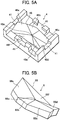
FIG. 5A is an explanatory perspective overall view showing an approximating opposing surface of a base mold component of the lower mold in the fiber reinforced composite member molding apparatus ofFIG. 2 . -
FIG. 5B is an explanatory perspective overall view showing an approximating opposing surface of the design mold component of the lower mold in the fiber reinforced composite member molding apparatus ofFIG. 2 . -
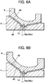
FIG. 6A is an explanatory cross-sectional view showing in what manner the approximating opposing surfaces of the base mold component and the design mold component of the lower mold, shown inFIG. 5 , are in contact with each other during cooling. -
FIG. 6B is an explanatory cross-sectional view showing in what manner the approximating opposing surfaces of the base mold component and the design mold component of the lower mold, shown inFIG. 5 , are in contact with each other during heating. -
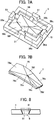
FIG. 7A is an explanatory perspective overall view showing an approximating opposing surface of a base mold component of an upper mold in the fiber reinforced composite member molding apparatus ofFIG. 2 . -
FIG. 7B is an explanatory perspective overall view showing an approximating opposing surface of a design mold component of the upper mold in the fiber reinforced composite member molding apparatus ofFIG. 2 . -
FIG. 8 is an explanatory plan fragmentary view showing a guide mechanism for the pair of molds in the fiber reinforced composite member molding apparatus ofFIG. 2 . -
FIG. 9A is an explanatory diagram showing how a load acts on a tip of a composite fan blade when the molds are clamped and pressed in the fiber reinforced composite member molding apparatus ofFIG. 2 . -
FIG. 9B is an explanatory diagram showing how a load acts on a hub of the composite fan blade when the molds are clamped and pressed in the fiber reinforced composite member molding apparatus ofFIG. 2 . -
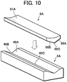
FIG. 10 is an explanatory exploded perspective view schematically showing a base mold component and a design mold component of a lower mold in another embodiment of fiber reinforced composite member molding apparatus according to this disclosure. - With reference to the accompanying drawings, an embodiment of fiber reinforced composite member molding apparatus according to this disclosure will be described below.
-
FIGS. 1A to 9B show an embodiment of fiber reinforced composite member molding apparatus according to this disclosure. - As shown in
FIGS. 1A and 1B , a fiber reinforced composite member to be molded is a composite fan blade FB of a turbofan engine with a blade tip FBt greatly twisted relative to a blade hub FBh. It is molded from a plurality of sheets of prepreg formed of long carbon fibers impregnated with resin, stacked such that sheets with differing fiber orientations form alternate layers. - As shown in
FIG. 2 , the fiber reinforced composite member molding apparatus 1 comprises a pair ofmolds molds lower mold 2 comprises abase mold component 4 fixed onto a bolster B and adesign mold component 6 detachably attached to thebase mold component 4. - For the
base mold component 4 of thelower mold 2, for example tool steel (SCM440) is used, and for thedesign mold component 6 thereof, an alloy with a low thermal expansion rate, such as invar (registered trademark), is used. - Of the two
molds upper mold 3 comprises abase mold component 5 fixed to a slide S moving up and down and adesign mold component 7 detachably attached to thebase mold component 5. In a clamped and pressed state in which pressure is applied to the molds from above and from below, thedesign mold component 7 clamps stacked sheets of prepreg, referred to as layered prepreg P (material to be molded into the composite fan blade FB), onto thedesign mold component 6 of thelower mold 2. - Also for the
base mold component 5 of theupper mold 3, for example tool steel (SCM440) is used, and for thedesign mold component 7 thereof, an alloy with a low thermal expansion rate, such as invar (registered trademark), is used. - As partially shown in
FIG. 3A , the molding apparatus 1 comprises induction heating coils (heat sources) 8 individually heating a plurality of regions of adesign surface 61 of thedesign mold component 6 of thelower mold 2 brought into contact with the layered prepreg P. - Specifically, the
design mold component 6 of thelower mold 2 has a plurality ofcells 62 provided along thedesign surface 61 to be open at the back of thedesign surface 61 and correspond to the regions of the design surface, and theinduction heating coils 8 are arranged in thecells 62, one for one. The induction heating coils 62 arranged in thecells 62, one for one, are electrically connected to each other. The manner of arranging aninduction heating coil 8 in eachcell 62 is not limited to that shown inFIG. 3A , namely arranging theinduction heating coil 8 to coil around an axis perpendicular to thedesign surface 61. Theinduction heating coil 8 may be arranged in the manner shown inFIG. 3B , namely arranged to coil around an axis running along thedesign surface 61. In place of theinduction heating coils 8, cartridge heaters may be used as heat sources. - As shown in
FIG, 4A , the molding apparatus 1 further comprises a plurality ofcooling passages 9 to allow a cooling fluid to flow to cool the layered prepreg P via thedesign mold component 6 of thelower mold 2. For the cooling fluid, a gas such as air or a liquid such as water can be used. - In the present embodiment, as partially shown in
FIG. 4A , thedesign mold component 6 of thelower mold 2 is formed by joining a plurality of design mold-constitutingplates 63 abutting each other by diffusion bonding. Specifically, the design mold-constitutingplates 63, standing in the direction in which themolds - The
cooling passages 9 are each formed by coolinggrooves 9a in adjacent design mold-constitutingplates 63 meeting each other when the design mold-constitutingplates 63 are diffusion-bonded. Thecooling grooves 9a are formed in the design mold-constitutingplates 63 in advance to run along thedesign surface 61. The distance d1 from thedesign surface 61 to eachcooling passage 9 and the distance d2 from thecell 62 thereto are determined depending on the thickness of the layered prepreg P which differs from part to part. This means that the distance between thecooling passage 9 and thecurved design surface 61 can be determined freely. In addition, thedesign mold component 6 can be cooled seamlessly, including the portions between thecells 62. - The cooling fluid is supplied to the
cooling passages 9 throughvertical holes 64, which are formed by machining after thedesign mold component 6 is made by diffusion bonding. - Although not shown, also the
design mold component 7 of theupper mold 3 comprises a plurality of cells provided along thedesign surface 71 to be open at the back of thedesign surface 71 and correspond to a plurality of regions of the design surface, andinduction heating coils 8 are arranged in the cells, one for one. Although not shown, also thedesign mold component 7 of theupper mold 3 is formed by joining a plurality of design mold-constituting plates by diffusion bonding, and cooling passages are formed between adjacent design mold-constituting plates to run along the design surface. - Thus, in the molding apparatus 1, thermoplastic resin contained in the layered prepreg P placed between the
lower mold 2 and theupper mold 3 is heated to a melting temperature (curing temperature when the matrix resin is thermosetting resin) or above by theinduction heating coils 8 arranged in thecells 62, one for one, and pressure is applied to the layered prereg P with the thermoplastic resin melted, by uniaxial pressing. - After the application of pressure, by causing the cooling fluid to flow in the
cooling passages 9 in thelower mold 2 and theupper mold 3, the thermoplastic resin is cooled to a temperature at which the resulting molded article does not experience damage or deformation by opening of the molds. The composite fan blade FB is obtained this way. - Further, as shown in
FIGS. 5A and 5B , thebase mold component 4 and thedesign mold component 6 of thelower mold 2 in the molding apparatus 1 have a concaveapproximating opposing surface 46 and a convexapproximating opposing surface 66, respectively. The approximating opposing surfaces are formed to approximate thedesign surface 61 of thedesign mold component 6 and adapted to be in contact with each other. - Here, as shown in
FIGS. 6A and 6B , thebase mold component 4 and thedesign mold component 6 are connected together with a thermal insulator 10 (ceramic thermal insulator withstanding the molding pressure, for example) interposed between them by a connectingpin 11 running through their centers 46o, 66o of thermal expansion in heating of the thermoplastic resin contained in the layered prepreg P. The approximating opposingsurfaces polygonal planes 46a to 46f arranged around the center 46o and a plurality ofpolygonal planes 66a to 66f arranged around the center 66o, respectively. - During cooling, the approximating opposing
surfaces base mold component 4 and thedesign mold component 6 are in contact with each other. During heating, even if only thedesign mold component 6 with theinduction heating coils 8 arranged therein experiences thermal expansion, the contact is maintained, because theapproximating opposing surfaces polygonal planes 46a to 46f arranged around the center 46o of thermal expansion and thepolygonal planes 66a to 66f arranged around the center 66o of thermal expansion, respectively, which allows thepolygonal planes 66a to 66f to be in sliding contact with the correspondingpolygonal planes 46a to 46f. Thus, as shown inFIG. 6B , the contact between the approximating opposingsurfaces pin 11 for connecting thebase mold component 4 and thedesign mold component 6 together is not indispensable, if the contact between the approximating opposingsurfaces - As shown in
FIGS. 7A and 7B , as is the case with thebase mold component 4 and thedesign mold component 6 of thelower mold 2, thebase mold component 5 and thedesign mold component 7 of theupper mold 3 have a concaveapproximating opposing surface 56 and a convexapproximating opposing surface 76, respectively. The approximating opposing surfaces are formed to approximate thedesign surface 71 of thedesign mold component 7 and adapted to be in contact with each other. Also the approximating opposingsurfaces polygonal planes 56a to 56f arranged around a center 56o of thermal expansion and a plurality ofpolygonal planes 76a to 76f arranged around a center 76o of thermal expansion in heating of the thermoplastic resin contained in the layered prepreg P, respectively. - The
base mold component 4 of thelower mold 2 in the molding apparatus 1 has dovetailgrooves 41 open to theupper mold 3 side, which constitute a guide mechanism. As shown inFIG. 5A , thedovetail grooves 41 are arranged at four locations in a manner surrounding theapproximating opposing surface 46. - The
base mold component 5 of theupper mold 3 in the molding apparatus 1 has dovetailtenons 51 projecting to thelower mold 2 side, which, in conjunction with thedovetail grooves 41, constitutes the guide mechanism. As shown inFIG. 7A , the dovetail tenons 51 are arranged at four locations in a manner surrounding theapproximating opposing surface 56. - In bringing the
lower mold 2 and theupper mold 3 into the clamped state, thedovetail grooves 41 of thebase mold component 4 of thelower mold 2 and the dovetail tenons 51 of thebase mold component 5 of theupper mold 3 guide them smoothly by engaging with each other as shown inFIG. 8 . - The
dovetail grooves 41 and the dovetail tenons 51 constituting the guide mechanism are provided such that even when there is a difference in the amount of thermal expansion between thebase mold component 4 of thelower mold 2 and thebase mold component 5 of theupper mold 3, eachdovetail groove 41 and thecorresponding dovetail tenon 51 can engage in a varying positional relationship, maintaining the face contact between their side walls, as indicated by chain lines and two-dot chain lines inFIG.8 , thereby absorbing the difference in the amount of thermal expansion. - Here, in the pressed state in which the
lower mold 2 and theupper mold 3 are clamped together and pressure is applied from above and from below, since the composite fan blade FB is greatly twisted, a horizontal component H of resin pressure Pr acts on the hub FBh and the tip FBt in opposite directions, as shown inFIGS. 9A and 9B . Thus, in the present embodiment, a fixed point is set at a point which does not produce unbalance between the horizontal components H acting on the hub FBh and the tip FBt, and the centers 46o, 66o (56o, 76o) of thermal expansion are determined based on the fixed point. - Next, a summary of how to mold a composite fan blade FB with the molding apparatus 1 will be given.
- First, the
design mold component 6 is connected to thebase mold component 4 of thelower mold 2 by means of the connectingpin 11, wherein the approximating opposingsurfaces base mold component 4 and thedesign mold component 6 of thelower mold 2 come into contact with each other, so that thedesign mold component 6 is stably attached to thebase mold component 4. - Next, the
design mold component 7 is connected to thebase mold component 5 of theupper mold 3, wherein the approximating opposingsurfaces base mold component 5 and thedesign mold component 7 of theupper mold 3 come into contact with each other, so that thedesign mold component 7 is stably attached to thebase mold component 5. - After the
molds design mold component 6 of thelower mold 2 in a mold open state. - Then, the
upper mold 3 is moved down with the slider S to bring the two molds into the clamped and pressed state, wherein the layered prepreg P is clamped between thedesign mold component 7 of theupper mold 3 and thedesign mold component 6 of thelower mold 2. - Here, the upper mold is guided smoothly by the dovetail tenons 51 of the
base mold component 5 of theupper mold 3 engaging with thedovetail grooves 41 of thebase mold component 4 of thelower mold 2. - Then, heat is applied to the layered prepreg P by the
induction coils 8 via thedesign mold component 6 and thedesign mold component 7 while pressure is applied to the layered prepreg P with the thermoplastic resin melted by theupper mold 3 and thelower mold 2. - Here, since the
induction heating coils 8 are arranged in thecells 62 provided along thedesign surface 61 of thedesign mold component 6 of thelower mold 2 to be open at the back of thedesign surface 61, one for one, thedesign mold component 6 of thelower mold 2 produces a uniform temperature distribution in heating. Thedesign mold component 7 of theupper mold 3 hasinduction heating coils 8 arranged in the same manner as in thelower mold 2, and thus, thedesign mold component 7 of theupper mold 3 produces a uniform temperature distribution in heating. - During heating, if only the
design mold component 6 with theinduction heating coils 8 provided therein experiences thermal expansion, the contact between the approximating opposingsurfaces base mold component 4 and thedesign mold component 6 is maintained, because they are composed of thepolygonal plane 46a to 46f arranged around the center 46o of thermal expansion and thepolygonal plane 66a to 66f arranged around the center 66o of thermal expansion, respectively, which allows thepolygonal planes 66a to 66f to be in sliding contact with the correspondingpolygonal planes 46a to 46f. In other words, production of a space between the approximating opposingsurfaces base mold component 4 and thedesign mold component 6 is avoided. - Further, if, in heating, there is a difference in the amount of thermal expansion between the
base mold component 4 of thelower mold 2 and thebase mold component 5 of theupper mold 3, thedovetail grooves 41 and the dovetail tenons 51, which constitute a guide mechanism, engage in a varying positional relationship, as indicated by chain lines and two-dot chain lines inFIG. 8 , thereby absorbing the difference in the amount of thermal expansion. - After the application of pressure, power supply to the
induction heating coils 8 is stopped, and the cooling fluid is caused to flow in thecooling passages 9 in thedesign mold component 7 of theupper mold 3 and thedesign mold component 6 of thelower mold 2 to cool the thermoplastic resin via thedesign mold components - In the molding apparatus 1, in heating, the
design mold component 6 of thelower mold 2 produces a uniform temperature distribution, because theinduction heating coils 8 are arranged in thecells 62 provided along thedesign surface 61 of thedesign mold component 6 of thelower mold 2 to be open at the back of thedesign surface 61, one for one (the same holds true for the upper mold 3). - In addition, in the molding apparatus 1, the
induction heating coils 8 provided as heat sources directly heat thelower mold 2, which allows thedesign mold components molds design mold components - In the molding apparatus 1, the
design mold component 6 of thelower mold 2 hascooling passages 9 running along thedesign surface 61. This makes it possible to cool thedesign mold component 6 not only at every point (cell 62) but also between points (between adjacent cells 62), thereby producing a uniform temperature distribution in cooling. - Here, the
design mold component 6 of thelower mold 2 is formed by joining a plurality of design mold-constitutingplates 63 abutting each other by diffusion bonding, wherein thecooling passages 9 in thedesign mold component 6 are each formed by coolinggrooves 9a in adjacent design mold-constitutingplates 63 meeting each other. Thecooling grooves 9a are formed in the design mold-constitutingplates 63 in advance to run along thedesign surface 61. This makes it possible to give a constant distance between thecooling passage 9 and thedesign surface 61 or vary the distance between them depending on the thickness of the layered prepreg P which varies from part to part. This also makes it possible to construct a three-dimensional cooling circuit. - When pressure is applied to the layered prepreg P by the
upper mold 3 and thelower mold 2, forces tending to cause lateral movement and forces tending to cause rotation act on theupper mold 3 or thelower mold 2. It is therefore favorable that thedovetail grooves 41 and the dovetail tenons 51 constituting the guide mechanism be formed to cancel out such forces. - The embodiment has been described based on an example in which the fiber reinforced composite member molding apparatus according to this disclosure is adapted to mold a composite fan blade FB of a turbofan engine having a great angle of twist. The fiber reinforced composite member molding apparatus according to this disclosure is however not limited to this example.
- For example, the fiber reinforced composite member molding apparatus according to this disclosure can be adapted to mold a composite stator vane of a turbofan engine, wherein a pair of molds each comprise a
base mold component 4A and adesign mold component 6A as partially shown inFIG. 10 , wherein thebase mold component 4A and thedesign mold component 6A have approximating opposing surfaces formed to approximate adesign surface 61A and composed ofrectangular planes centerline 460 of thermal expansion and abutting each other andrectangular planes centerline 660 of thermal expansion and abutting each other, respectively. - In the fiber reinforced composite member molding apparatus disclosed herein, resins usable as a matrix to form prepreg include thermoplastic resins such as PEEK (polyether ether ketone resin), PEI (polyetherimide resin) and PIXA (thermoplastic polyimide resin), and thermosetting resins such as epoxy resin, phenol resin and polyimide resin.
- A first aspect according to this disclosure is a fiber reinforced composite member molding apparatus for molding a fiber reinforced composite member from stacked sheets of prepreg formed of long carbon fibers impregnated with resin, comprising a pair of molds provided to be brought nearer to or away from each other, heat sources to heat the resin contained in the prepreg via the molds in a clamped and pressed state with the stacked sheets of prereg clamped between the molds, and cooling passages to allow a cooling fluid to flow, thereby cooling the resin via the molds after heating of the resin contained in the prepreg, wherein the molds each have a design surface brought into contact with the stacked sheets of prereg, the design surface being divided into a plurality of regions, and a plurality of cells provided along the design surface to be open at the back of the design surface and individually correspond to the regions of the design surface, the heat sources are individually arranged in the cells, and the cooling passages are formed in each of the molds to run along the design surface.
- In the fiber reinforce composite member molding apparatus according to the first aspect in this disclosure, heat sources are arranged in the cells provided along the design surface of each of the molds to be open at the back of the design surface, one for one, and cooling passages are provided to run along the design surface of each of the molds. This makes it possible to produce a uniform temperature distribution in heating and cooling of the molds.
- In heating of the molds, the molds are heated directly by the heat sources, which allows the molds to have an increased thickness near the design surface as compared with indirect heating in the conventional art, wherein the molds are heated by blowing air heated by heating portions of heaters to the back of the design surface of each mold, and thus, allow the molds to have an accordingly-increased, sufficient rigidity.
- In a second aspect according to this disclosure, the molds each comprise a base mold component and a design mold component providing the design surface and detachably attached to the base mold component with a thermal insulator interposed therebetween, the design mold component of each of the molds is formed by joining a plurality of design mold-constituting plates, arranged to abut each other in a position standing in the direction in which the molds are brought nearer to or away from each other, by diffusion bonding, and the design mold-constituting plates have cooling grooves provided such that the cooling grooves in adjacent design mold-constituting plates meet each other to form the cooling passages.
- In the fiber reinforced composite member molding apparatus according to the second aspect in this disclosure, when the design mold component of the mold is formed by joining the design mold-constituting plates abutting each other by diffusion bonding, the cooling passages are formed by cooling grooves in adjacent design mold-constituting plates meeting each other, wherein the cooling grooves are formed in the design mold-constituting plates in advance to run along the design surface. This makes it possible to give a constant distance between the cooling passage and the design surface or vary the distance between them depending on the thickness of the stacked sheets of prepreg which varies from part to part. This also makes it possible to construct a three-dimensional cooling circuit.
- In a third aspect according to this disclosure, the base mold component and the design mold component of each of the molds have approximating opposing surfaces formed to approximate the design surface, the approximating opposing surfaces of the base mold component and the design mold component each comprising a plurality of polygonal planes arranged around a center of thermal expansion in heating of the resin contained in the prepreg and abutting each other.
- In the fiber reinforced composite member molding apparatus according to the third aspect in this disclosure, the approximating opposing surfaces of the base mold component and the design mold component of each of the molds, which are in contact with each other during cooling, maintain the contact even if only the design mold component experiences thermal expansion during heating, because the polygonal planes of the design mold component arranged around the center of thermal expansion are in sliding contact with the corresponding polygonal planes of the base mold component.
- In a fourth aspect according to this disclosure, the base mold component and the design mold component are connected together by a connecting member running through their centers of thermal expansion.
- In the fiber reinforced composite member molding apparatus according to the fourth aspect in this disclosure, the contact between the approximating opposing surfaces of the base mold component and the design mold component is maintained satisfactorily and reliably in heating and cooling.
- In fifth to seventh aspects according to this disclosure, the base mold components of the molds have a guide mechanism for guiding the molds in movement relative to each other and absorbing a difference in the amount of thermal expansion between the molds.
- In the fiber reinforced composite member molding apparatus according to any of the fifth to seventh aspects in this disclosure, when the molds are brought into the clamped state, the guide mechanism smoothly guides the molds, and when there is a difference in the amount of thermal expansion between the molds, the guide mechanism absorbs the difference in the amount of thermal expansion.
- In an eighth aspect according to this disclosure, the base mold component and the design mold component of each of the molds have approximating opposing surfaces formed to approximate the design surface, the approximating opposing surfaces of the base mold component and the design mold component each comprising a plurality of rectangular planes arranged to opposite sides of a centerline of thermal expansion in heating of the resin contained in the prepreg and abutting each other.
- In the fiber reinforced composite member molding apparatus according to the eighth aspect in this disclosure, the approximating opposing surfaces of the base mold component and the design mold component of each of the molds, which are in contact with each other during cooling, maintain the contact even if only the design mold component experiences thermal expansion during heating, because the rectangular planes of the design mold component arranged to the opposite sides of the centerline of thermal expansion are in sliding contact with the corresponding rectangular planes of the base mold component.
-
- 1 Fiber reinforced composite member molding apparatus
- 2 Lower mold (forming a pair of molds)
- 3 Upper mold (forming a pair of molds)
- 4, 4A, 5 Base mold component
- 6, 6A, 7 Design mold component
- 8 Induction heating coil (heat source)
- 9 Cooling passage
- 9a Cooling groove
- 10 Thermal insulator
- 11 Connecting pin (connecting member)
- 41 Dovetail groove (guide mechanism)
- 46, 56 Approximating opposing surface
- 46a to 46f Polygonal plane
- 46o, 66o Center of thermal expansion
- 46A, 66B Rectangular plane
- 460, 660 Centerline of thermal expansion
- 51 Dovetail tenon (guide mechanism)
- 56a to 56f Polygonal plane
- 56o, 76o Center of thermal expansion
- 71, 61A, 71 Design surface
- 62 Cell
- 63 Design mold-constituting plate
- 64 Vertical hole
- 66, 76 Approximating opposing surface
- 66a to 66f Polygonal plane
- 66A, 66B Rectangular plane
- 76a to 76f Polygonal plane
- FB Composite fan blade (fiber reinforced composite member)
- P Layered prepreg (prepreg)
Claims (8)
- A fiber reinforced composite member molding apparatus for molding a fiber reinforced composite member from stacked sheets of prepreg formed of long carbon fibers impregnated with resin, comprising:a pair of molds provided to be brought nearer to or away from each other,heat sources to heat the resin contained in the prepreg via the molds in a clamped and pressed state with the stacked sheets of prereg clamped between the molds, andcooling passages to allow a cooling fluid to flow, thereby cooling the resin via the molds after heating of the resin contained in the prepreg, whereinthe molds have each a design surface brought into contact with the stacked sheets of prereg, the design surface being divided into a plurality of regions, and a plurality of cells provided along the design surface to be open at the back of the design surface and individually correspond to the regions of the design surface,the heat sources are individually arranged in the cells, andthe cooling passages are formed in each of the molds to run along the design surface.
- The fiber reinforced composite member molding apparatus according to claim 1, wherein the molds each comprise a base mold component and a design mold component providing the design surface and detachably attached to the base mold component with a thermal insulator interposed therebetween, the design mold component of each of the molds is formed by joining a plurality of design mold-constituting plates, arranged to abut each other in a position standing in the direction in which the molds are brought nearer to or away from each other, by diffusion bonding, and the design mold-constituting plates have cooling grooves provided such that the cooling grooves in adjacent design mold-constituting plates meet each other to form the cooling passages.
- The fiber reinforced composite member molding apparatus according to claim 2, wherein the base mold component and the design mold component of each of the molds have approximating opposing surfaces formed to approximate the design surface, the approximating opposing surfaces of the base mold component and the design mold component each comprising a plurality of polygonal planes arranged around a center of thermal expansion in heating of the resin contained in the prepreg and abutting each other.
- The fiber reinforced composite member molding apparatus according to claim 3, wherein the base mold component and the design mold component are connected together by a connecting member running through the centers of thermal expansion.
- The fiber reinforced composite member molding apparatus according to claim 2, wherein the base mold components of the molds have a guide mechanism for guiding the molds in movement relative to each other and absorbing a difference in the amount of thermal expansion between the molds.
- The fiber reinforced composite member molding apparatus according to claim 3, wherein the base mold components of the molds have a guide mechanism for guiding the molds in movement relative to each other and absorbing a difference in the amount of thermal expansion between the molds.
- The fiber reinforced composite member molding apparatus according to claim 4, wherein the base mold components of the molds have a guide mechanism for guiding the molds in movement relative to each other and absorbing a difference in the amount of thermal expansion between the molds.
- The fiber reinforced composite member molding apparatus according to claim 2, wherein the base mold component and the design mold component of each of the molds have approximating opposing surfaces each formed to approximate the design surface, the approximating opposing surfaces of the base mold component and the design mold component each comprising a plurality of rectangular planes arranged to opposite sides of a centerline of thermal expansion in heating of the resin contained in the prepreg and abutting each other.
Applications Claiming Priority (2)
| Application Number | Priority Date | Filing Date | Title |
|---|---|---|---|
| JP2016008969A JP6645841B2 (en) | 2016-01-20 | 2016-01-20 | Fiber reinforced composite member molding equipment |
| PCT/JP2016/077846 WO2017126158A1 (en) | 2016-01-20 | 2016-09-21 | Fiber-reinforced composite member molding device |
Publications (3)
| Publication Number | Publication Date |
|---|---|
| EP3406412A1 true EP3406412A1 (en) | 2018-11-28 |
| EP3406412A4 EP3406412A4 (en) | 2019-08-28 |
| EP3406412B1 EP3406412B1 (en) | 2020-05-06 |
Family
ID=59361846
Family Applications (1)
| Application Number | Title | Priority Date | Filing Date |
|---|---|---|---|
| EP16886398.3A Active EP3406412B1 (en) | 2016-01-20 | 2016-09-21 | Fiber-reinforced composite member molding apparatus |
Country Status (7)
| Country | Link |
|---|---|
| US (1) | US11052574B2 (en) |
| EP (1) | EP3406412B1 (en) |
| JP (1) | JP6645841B2 (en) |
| CN (1) | CN108472841B (en) |
| CA (1) | CA3009776C (en) |
| RU (1) | RU2693729C1 (en) |
| WO (1) | WO2017126158A1 (en) |
Cited By (3)
| Publication number | Priority date | Publication date | Assignee | Title |
|---|---|---|---|---|
| AT524530B1 (en) * | 2021-04-13 | 2022-07-15 | Sg Concepts Gmbh | Process for the production of a plastic component, in particular a fiber-reinforced one, and a supporting structure for supporting the plastic component |
| EP4105008A1 (en) * | 2021-06-14 | 2022-12-21 | The Boeing Company | Inductively heated slip sheet and methods of using |
| DE102021121225A1 (en) | 2021-08-16 | 2023-02-16 | Deutsches Zentrum für Luft- und Raumfahrt e.V. | pressing tool |
Families Citing this family (7)
| Publication number | Priority date | Publication date | Assignee | Title |
|---|---|---|---|---|
| DE102018009331A1 (en) * | 2018-11-28 | 2020-05-28 | Senvion Gmbh | Rotor blade shape and method for producing a rotor blade for a wind turbine and a wind turbine |
| CN111941776A (en) * | 2019-05-15 | 2020-11-17 | 苏州汉扬精密电子有限公司 | Electromagnetic heating structure of mold |
| WO2021195762A1 (en) * | 2020-04-01 | 2021-10-07 | Proslide Technology Inc. | Water slide segment with spacer layer and methods of manufacture therefor |
| CN112659426A (en) * | 2020-11-11 | 2021-04-16 | 深圳市金源康实业有限公司 | Carbon fiber secondary forming processing technology |
| CN113400527B (en) * | 2021-07-08 | 2023-04-11 | 湖南航天环宇通信科技股份有限公司 | Integral compression molding die and molding process for composite material multidirectional connector |
| EP4696486A1 (en) * | 2023-04-14 | 2026-02-18 | IHI Aerospace Co., Ltd. | Method for joining members made of material containing thermoplastic resin |
| CN120863107B (en) * | 2025-09-24 | 2026-01-09 | 鸿安(福建)机械有限公司 | Forming process and forming device for carbon fiber plate body |
Family Cites Families (17)
| Publication number | Priority date | Publication date | Assignee | Title |
|---|---|---|---|---|
| US5108691A (en) * | 1986-09-03 | 1992-04-28 | Astechnologies, Inc. | Compressing and shaping thermoformable mats using superheated steam |
| JPH0673903B2 (en) * | 1988-09-27 | 1994-09-21 | 宇部興産株式会社 | Mold device for molding hollow molded product and method for molding hollow molded product |
| US5139407A (en) * | 1989-09-01 | 1992-08-18 | General Electric Company | Apparatus for reducing thermoplastic material compression mold cycle time |
| US5829716A (en) * | 1995-06-07 | 1998-11-03 | The Boeing Company | Welded aerospace structure using a hybrid metal webbed composite beam |
| US5688426A (en) * | 1995-06-07 | 1997-11-18 | The Boeing Company | Hybrid metal webbed composite beam |
| JP3651163B2 (en) * | 1997-03-10 | 2005-05-25 | トヨタ紡織株式会社 | Molding device with heating mechanism |
| JP4463492B2 (en) * | 2003-04-10 | 2010-05-19 | 株式会社半導体エネルギー研究所 | Manufacturing equipment |
| JP3930848B2 (en) * | 2003-10-22 | 2007-06-13 | 株式会社榊原鈑金 | Mold for fiber assembly |
| DE10360110B4 (en) * | 2003-12-12 | 2011-04-14 | Fraunhofer-Gesellschaft zur Förderung der angewandten Forschung e.V. | Temperable component |
| US20060249872A1 (en) * | 2005-01-18 | 2006-11-09 | Mark Manuel | Compound mold tooling for controlled heat transfer |
| KR20090064362A (en) * | 2006-08-01 | 2009-06-18 | 미쓰비시 엔지니어링-플라스틱스 코포레이션 | Mold assembly |
| JP2009292054A (en) * | 2008-06-05 | 2009-12-17 | Motoyasu Hibi | Method for press-molding fiber-reinforced plastic |
| US8511362B2 (en) * | 2009-01-16 | 2013-08-20 | Edwin H. Kintz | Consolidating and curing of thermoset composite parts by pressing between a heated rigid mold and customized rubber-faced mold |
| CA2778085C (en) * | 2009-10-20 | 2018-01-16 | Surface Generation Limited | Zone control of tool temperature |
| JP5513079B2 (en) * | 2009-11-06 | 2014-06-04 | 三菱レイヨン株式会社 | Mold and method for producing thermoplastic resin fiber reinforced composite material molded article |
| JP5473711B2 (en) * | 2010-03-26 | 2014-04-16 | 日新製鋼株式会社 | Laminated mold for resin molding and method for producing the same |
| JP2015160393A (en) * | 2014-02-28 | 2015-09-07 | パナソニックIpマネジメント株式会社 | Decorative molding equipment for thermoplastic FRP |
-
2016
- 2016-01-20 JP JP2016008969A patent/JP6645841B2/en active Active
- 2016-09-21 RU RU2018129099A patent/RU2693729C1/en active
- 2016-09-21 CA CA3009776A patent/CA3009776C/en active Active
- 2016-09-21 CN CN201680076495.3A patent/CN108472841B/en not_active Expired - Fee Related
- 2016-09-21 EP EP16886398.3A patent/EP3406412B1/en active Active
- 2016-09-21 WO PCT/JP2016/077846 patent/WO2017126158A1/en not_active Ceased
-
2018
- 2018-06-25 US US16/017,234 patent/US11052574B2/en active Active
Cited By (5)
| Publication number | Priority date | Publication date | Assignee | Title |
|---|---|---|---|---|
| AT524530B1 (en) * | 2021-04-13 | 2022-07-15 | Sg Concepts Gmbh | Process for the production of a plastic component, in particular a fiber-reinforced one, and a supporting structure for supporting the plastic component |
| AT524530A4 (en) * | 2021-04-13 | 2022-07-15 | Sg Concepts Gmbh | Process for the production of a plastic component, in particular a fiber-reinforced one, and a supporting structure for supporting the plastic component |
| EP4105008A1 (en) * | 2021-06-14 | 2022-12-21 | The Boeing Company | Inductively heated slip sheet and methods of using |
| US12285887B2 (en) | 2021-06-14 | 2025-04-29 | The Boeing Company | Inductively heated slip sheet and methods of using |
| DE102021121225A1 (en) | 2021-08-16 | 2023-02-16 | Deutsches Zentrum für Luft- und Raumfahrt e.V. | pressing tool |
Also Published As
| Publication number | Publication date |
|---|---|
| WO2017126158A1 (en) | 2017-07-27 |
| EP3406412A4 (en) | 2019-08-28 |
| CA3009776A1 (en) | 2017-07-27 |
| CN108472841A (en) | 2018-08-31 |
| RU2693729C1 (en) | 2019-07-04 |
| CA3009776C (en) | 2020-03-10 |
| CN108472841B (en) | 2020-07-03 |
| US11052574B2 (en) | 2021-07-06 |
| US20180304496A1 (en) | 2018-10-25 |
| EP3406412B1 (en) | 2020-05-06 |
| JP2017128035A (en) | 2017-07-27 |
| JP6645841B2 (en) | 2020-02-14 |
Similar Documents
| Publication | Publication Date | Title |
|---|---|---|
| US11052574B2 (en) | Fiber reinforced composite member molding apparatus | |
| CN111716758B (en) | Co-consolidation tools and related methods | |
| EP2070678B1 (en) | Process for the production of preforms and fiber-reinforced plastics with the mold | |
| EP2881238B1 (en) | Aerospace structural member with hybrid composite structure | |
| US6162314A (en) | Thermal welding of fiber reinforced thermoplastic prepreg | |
| EP2886251B1 (en) | Method of securing composite core during a manufacturing process | |
| US11826976B2 (en) | FRP molding system and method | |
| US10232569B2 (en) | Device and method for manufacturing fiber-reinforced plastic structure | |
| US8845946B2 (en) | Method and device for manufacturing a fiber composite component with an integral structural design | |
| CN103298593B (en) | The manufacturing installation of preform and manufacture method and the preform manufactured by the method | |
| EP3348378A1 (en) | Composite material production method, composite material production device, preform for composite material, and composite material | |
| CN101652238A (en) | Method for producing profile parts | |
| RU2671346C1 (en) | Method for production composite material and composite material producing device | |
| JP2011516295A (en) | Method for tolerance compensation between two fiber composite components | |
| US20180304562A1 (en) | Fiber reinforced composite member molding apparatus and fiber reinforced composite member molding method | |
| US20180104862A1 (en) | Fiber reinforced composite member molding apparatus | |
| JP6170347B2 (en) | Manufacturing method and mold for fiber reinforced plastic structure | |
| JP7629322B2 (en) | Manufacturing method for joint parts | |
| JP2024516180A5 (en) | ||
| JP5564233B2 (en) | Resin casting mold and its manufacturing method | |
| US20240239061A1 (en) | Method of Manufacturing a Component from a Composite Material with Locally Different Thicknesses | |
| Gaddikeri et al. | Innovative tooling concepts for cocured composite structures in aircraft applications |
Legal Events
| Date | Code | Title | Description |
|---|---|---|---|
| STAA | Information on the status of an ep patent application or granted ep patent |
Free format text: STATUS: THE INTERNATIONAL PUBLICATION HAS BEEN MADE |
|
| PUAI | Public reference made under article 153(3) epc to a published international application that has entered the european phase |
Free format text: ORIGINAL CODE: 0009012 |
|
| STAA | Information on the status of an ep patent application or granted ep patent |
Free format text: STATUS: REQUEST FOR EXAMINATION WAS MADE |
|
| 17P | Request for examination filed |
Effective date: 20180820 |
|
| AK | Designated contracting states |
Kind code of ref document: A1 Designated state(s): AL AT BE BG CH CY CZ DE DK EE ES FI FR GB GR HR HU IE IS IT LI LT LU LV MC MK MT NL NO PL PT RO RS SE SI SK SM TR |
|
| AX | Request for extension of the european patent |
Extension state: BA ME |
|
| DAV | Request for validation of the european patent (deleted) | ||
| DAX | Request for extension of the european patent (deleted) | ||
| A4 | Supplementary search report drawn up and despatched |
Effective date: 20190731 |
|
| RIC1 | Information provided on ipc code assigned before grant |
Ipc: B29C 33/06 20060101ALI20190725BHEP Ipc: B29K 105/08 20060101ALI20190725BHEP Ipc: B29C 70/34 20060101ALI20190725BHEP Ipc: B29C 35/08 20060101ALN20190725BHEP Ipc: B29C 43/36 20060101ALI20190725BHEP Ipc: B29C 33/02 20060101ALN20190725BHEP Ipc: B29C 35/16 20060101ALN20190725BHEP Ipc: B29C 43/52 20060101AFI20190725BHEP Ipc: B29L 31/08 20060101ALN20190725BHEP Ipc: B29C 33/30 20060101ALI20190725BHEP Ipc: B29C 33/04 20060101ALN20190725BHEP |
|
| GRAP | Despatch of communication of intention to grant a patent |
Free format text: ORIGINAL CODE: EPIDOSNIGR1 |
|
| STAA | Information on the status of an ep patent application or granted ep patent |
Free format text: STATUS: GRANT OF PATENT IS INTENDED |
|
| RIC1 | Information provided on ipc code assigned before grant |
Ipc: B29C 70/34 20060101ALI20191219BHEP Ipc: B29C 35/08 20060101ALN20191219BHEP Ipc: B29C 43/36 20060101ALN20191219BHEP Ipc: B29C 33/02 20060101ALN20191219BHEP Ipc: B29C 35/16 20060101ALN20191219BHEP Ipc: B29C 43/52 20060101AFI20191219BHEP Ipc: B29C 33/04 20060101ALN20191219BHEP Ipc: B29L 31/08 20060101ALN20191219BHEP Ipc: B29C 33/30 20060101ALI20191219BHEP Ipc: B29K 105/08 20060101ALI20191219BHEP Ipc: B29C 33/06 20060101ALI20191219BHEP |
|
| INTG | Intention to grant announced |
Effective date: 20200110 |
|
| GRAS | Grant fee paid |
Free format text: ORIGINAL CODE: EPIDOSNIGR3 |
|
| GRAA | (expected) grant |
Free format text: ORIGINAL CODE: 0009210 |
|
| STAA | Information on the status of an ep patent application or granted ep patent |
Free format text: STATUS: THE PATENT HAS BEEN GRANTED |
|
| AK | Designated contracting states |
Kind code of ref document: B1 Designated state(s): AL AT BE BG CH CY CZ DE DK EE ES FI FR GB GR HR HU IE IS IT LI LT LU LV MC MK MT NL NO PL PT RO RS SE SI SK SM TR |
|
| REG | Reference to a national code |
Ref country code: GB Ref legal event code: FG4D |
|
| REG | Reference to a national code |
Ref country code: CH Ref legal event code: EP Ref country code: AT Ref legal event code: REF Ref document number: 1266057 Country of ref document: AT Kind code of ref document: T Effective date: 20200515 |
|
| REG | Reference to a national code |
Ref country code: IE Ref legal event code: FG4D |
|
| REG | Reference to a national code |
Ref country code: DE Ref legal event code: R096 Ref document number: 602016036209 Country of ref document: DE |
|
| REG | Reference to a national code |
Ref country code: LT Ref legal event code: MG4D |
|
| REG | Reference to a national code |
Ref country code: NL Ref legal event code: MP Effective date: 20200506 |
|
| PG25 | Lapsed in a contracting state [announced via postgrant information from national office to epo] |
Ref country code: LT Free format text: LAPSE BECAUSE OF FAILURE TO SUBMIT A TRANSLATION OF THE DESCRIPTION OR TO PAY THE FEE WITHIN THE PRESCRIBED TIME-LIMIT Effective date: 20200506 Ref country code: FI Free format text: LAPSE BECAUSE OF FAILURE TO SUBMIT A TRANSLATION OF THE DESCRIPTION OR TO PAY THE FEE WITHIN THE PRESCRIBED TIME-LIMIT Effective date: 20200506 Ref country code: NO Free format text: LAPSE BECAUSE OF FAILURE TO SUBMIT A TRANSLATION OF THE DESCRIPTION OR TO PAY THE FEE WITHIN THE PRESCRIBED TIME-LIMIT Effective date: 20200806 Ref country code: GR Free format text: LAPSE BECAUSE OF FAILURE TO SUBMIT A TRANSLATION OF THE DESCRIPTION OR TO PAY THE FEE WITHIN THE PRESCRIBED TIME-LIMIT Effective date: 20200807 Ref country code: SE Free format text: LAPSE BECAUSE OF FAILURE TO SUBMIT A TRANSLATION OF THE DESCRIPTION OR TO PAY THE FEE WITHIN THE PRESCRIBED TIME-LIMIT Effective date: 20200506 Ref country code: IS Free format text: LAPSE BECAUSE OF FAILURE TO SUBMIT A TRANSLATION OF THE DESCRIPTION OR TO PAY THE FEE WITHIN THE PRESCRIBED TIME-LIMIT Effective date: 20200906 Ref country code: PT Free format text: LAPSE BECAUSE OF FAILURE TO SUBMIT A TRANSLATION OF THE DESCRIPTION OR TO PAY THE FEE WITHIN THE PRESCRIBED TIME-LIMIT Effective date: 20200907 |
|
| PG25 | Lapsed in a contracting state [announced via postgrant information from national office to epo] |
Ref country code: LV Free format text: LAPSE BECAUSE OF FAILURE TO SUBMIT A TRANSLATION OF THE DESCRIPTION OR TO PAY THE FEE WITHIN THE PRESCRIBED TIME-LIMIT Effective date: 20200506 Ref country code: RS Free format text: LAPSE BECAUSE OF FAILURE TO SUBMIT A TRANSLATION OF THE DESCRIPTION OR TO PAY THE FEE WITHIN THE PRESCRIBED TIME-LIMIT Effective date: 20200506 Ref country code: HR Free format text: LAPSE BECAUSE OF FAILURE TO SUBMIT A TRANSLATION OF THE DESCRIPTION OR TO PAY THE FEE WITHIN THE PRESCRIBED TIME-LIMIT Effective date: 20200506 Ref country code: BG Free format text: LAPSE BECAUSE OF FAILURE TO SUBMIT A TRANSLATION OF THE DESCRIPTION OR TO PAY THE FEE WITHIN THE PRESCRIBED TIME-LIMIT Effective date: 20200806 |
|
| REG | Reference to a national code |
Ref country code: AT Ref legal event code: MK05 Ref document number: 1266057 Country of ref document: AT Kind code of ref document: T Effective date: 20200506 |
|
| PG25 | Lapsed in a contracting state [announced via postgrant information from national office to epo] |
Ref country code: NL Free format text: LAPSE BECAUSE OF FAILURE TO SUBMIT A TRANSLATION OF THE DESCRIPTION OR TO PAY THE FEE WITHIN THE PRESCRIBED TIME-LIMIT Effective date: 20200506 Ref country code: AL Free format text: LAPSE BECAUSE OF FAILURE TO SUBMIT A TRANSLATION OF THE DESCRIPTION OR TO PAY THE FEE WITHIN THE PRESCRIBED TIME-LIMIT Effective date: 20200506 |
|
| PG25 | Lapsed in a contracting state [announced via postgrant information from national office to epo] |
Ref country code: DK Free format text: LAPSE BECAUSE OF FAILURE TO SUBMIT A TRANSLATION OF THE DESCRIPTION OR TO PAY THE FEE WITHIN THE PRESCRIBED TIME-LIMIT Effective date: 20200506 Ref country code: SM Free format text: LAPSE BECAUSE OF FAILURE TO SUBMIT A TRANSLATION OF THE DESCRIPTION OR TO PAY THE FEE WITHIN THE PRESCRIBED TIME-LIMIT Effective date: 20200506 Ref country code: AT Free format text: LAPSE BECAUSE OF FAILURE TO SUBMIT A TRANSLATION OF THE DESCRIPTION OR TO PAY THE FEE WITHIN THE PRESCRIBED TIME-LIMIT Effective date: 20200506 Ref country code: EE Free format text: LAPSE BECAUSE OF FAILURE TO SUBMIT A TRANSLATION OF THE DESCRIPTION OR TO PAY THE FEE WITHIN THE PRESCRIBED TIME-LIMIT Effective date: 20200506 Ref country code: ES Free format text: LAPSE BECAUSE OF FAILURE TO SUBMIT A TRANSLATION OF THE DESCRIPTION OR TO PAY THE FEE WITHIN THE PRESCRIBED TIME-LIMIT Effective date: 20200506 Ref country code: RO Free format text: LAPSE BECAUSE OF FAILURE TO SUBMIT A TRANSLATION OF THE DESCRIPTION OR TO PAY THE FEE WITHIN THE PRESCRIBED TIME-LIMIT Effective date: 20200506 Ref country code: CZ Free format text: LAPSE BECAUSE OF FAILURE TO SUBMIT A TRANSLATION OF THE DESCRIPTION OR TO PAY THE FEE WITHIN THE PRESCRIBED TIME-LIMIT Effective date: 20200506 |
|
| REG | Reference to a national code |
Ref country code: DE Ref legal event code: R097 Ref document number: 602016036209 Country of ref document: DE |
|
| PG25 | Lapsed in a contracting state [announced via postgrant information from national office to epo] |
Ref country code: SK Free format text: LAPSE BECAUSE OF FAILURE TO SUBMIT A TRANSLATION OF THE DESCRIPTION OR TO PAY THE FEE WITHIN THE PRESCRIBED TIME-LIMIT Effective date: 20200506 Ref country code: PL Free format text: LAPSE BECAUSE OF FAILURE TO SUBMIT A TRANSLATION OF THE DESCRIPTION OR TO PAY THE FEE WITHIN THE PRESCRIBED TIME-LIMIT Effective date: 20200506 |
|
| PLBE | No opposition filed within time limit |
Free format text: ORIGINAL CODE: 0009261 |
|
| STAA | Information on the status of an ep patent application or granted ep patent |
Free format text: STATUS: NO OPPOSITION FILED WITHIN TIME LIMIT |
|
| 26N | No opposition filed |
Effective date: 20210209 |
|
| REG | Reference to a national code |
Ref country code: CH Ref legal event code: PL |
|
| PG25 | Lapsed in a contracting state [announced via postgrant information from national office to epo] |
Ref country code: SI Free format text: LAPSE BECAUSE OF FAILURE TO SUBMIT A TRANSLATION OF THE DESCRIPTION OR TO PAY THE FEE WITHIN THE PRESCRIBED TIME-LIMIT Effective date: 20200506 |
|
| REG | Reference to a national code |
Ref country code: BE Ref legal event code: MM Effective date: 20200930 |
|
| PG25 | Lapsed in a contracting state [announced via postgrant information from national office to epo] |
Ref country code: LU Free format text: LAPSE BECAUSE OF NON-PAYMENT OF DUE FEES Effective date: 20200921 |
|
| PG25 | Lapsed in a contracting state [announced via postgrant information from national office to epo] |
Ref country code: IE Free format text: LAPSE BECAUSE OF NON-PAYMENT OF DUE FEES Effective date: 20200921 Ref country code: LI Free format text: LAPSE BECAUSE OF NON-PAYMENT OF DUE FEES Effective date: 20200930 Ref country code: CH Free format text: LAPSE BECAUSE OF NON-PAYMENT OF DUE FEES Effective date: 20200930 Ref country code: BE Free format text: LAPSE BECAUSE OF NON-PAYMENT OF DUE FEES Effective date: 20200930 |
|
| PG25 | Lapsed in a contracting state [announced via postgrant information from national office to epo] |
Ref country code: TR Free format text: LAPSE BECAUSE OF FAILURE TO SUBMIT A TRANSLATION OF THE DESCRIPTION OR TO PAY THE FEE WITHIN THE PRESCRIBED TIME-LIMIT Effective date: 20200506 Ref country code: MT Free format text: LAPSE BECAUSE OF FAILURE TO SUBMIT A TRANSLATION OF THE DESCRIPTION OR TO PAY THE FEE WITHIN THE PRESCRIBED TIME-LIMIT Effective date: 20200506 Ref country code: CY Free format text: LAPSE BECAUSE OF FAILURE TO SUBMIT A TRANSLATION OF THE DESCRIPTION OR TO PAY THE FEE WITHIN THE PRESCRIBED TIME-LIMIT Effective date: 20200506 |
|
| PG25 | Lapsed in a contracting state [announced via postgrant information from national office to epo] |
Ref country code: MK Free format text: LAPSE BECAUSE OF FAILURE TO SUBMIT A TRANSLATION OF THE DESCRIPTION OR TO PAY THE FEE WITHIN THE PRESCRIBED TIME-LIMIT Effective date: 20200506 Ref country code: MC Free format text: LAPSE BECAUSE OF FAILURE TO SUBMIT A TRANSLATION OF THE DESCRIPTION OR TO PAY THE FEE WITHIN THE PRESCRIBED TIME-LIMIT Effective date: 20200506 |
|
| PGFP | Annual fee paid to national office [announced via postgrant information from national office to epo] |
Ref country code: IT Payment date: 20220825 Year of fee payment: 7 |
|
| PG25 | Lapsed in a contracting state [announced via postgrant information from national office to epo] |
Ref country code: IT Free format text: LAPSE BECAUSE OF NON-PAYMENT OF DUE FEES Effective date: 20230921 |
|
| PG25 | Lapsed in a contracting state [announced via postgrant information from national office to epo] |
Ref country code: IT Free format text: LAPSE BECAUSE OF NON-PAYMENT OF DUE FEES Effective date: 20230921 |
|
| PGFP | Annual fee paid to national office [announced via postgrant information from national office to epo] |
Ref country code: DE Payment date: 20250820 Year of fee payment: 10 |
|
| PGFP | Annual fee paid to national office [announced via postgrant information from national office to epo] |
Ref country code: GB Payment date: 20250820 Year of fee payment: 10 |
|
| PGFP | Annual fee paid to national office [announced via postgrant information from national office to epo] |
Ref country code: FR Payment date: 20250821 Year of fee payment: 10 |