EP3406201A2 - Bone anchor including only suture material and delivery device thereof - Google Patents
Bone anchor including only suture material and delivery device thereof Download PDFInfo
- Publication number
- EP3406201A2 EP3406201A2 EP18000458.2A EP18000458A EP3406201A2 EP 3406201 A2 EP3406201 A2 EP 3406201A2 EP 18000458 A EP18000458 A EP 18000458A EP 3406201 A2 EP3406201 A2 EP 3406201A2
- Authority
- EP
- European Patent Office
- Prior art keywords
- suture
- draw bar
- anchor
- tubular
- delivery device
- Prior art date
- Legal status (The legal status is an assumption and is not a legal conclusion. Google has not performed a legal analysis and makes no representation as to the accuracy of the status listed.)
- Granted
Links
Images





Classifications
-
- A—HUMAN NECESSITIES
- A61—MEDICAL OR VETERINARY SCIENCE; HYGIENE
- A61B—DIAGNOSIS; SURGERY; IDENTIFICATION
- A61B17/00—Surgical instruments, devices or methods
- A61B17/04—Surgical instruments, devices or methods for suturing wounds; Holders or packages for needles or suture materials
- A61B17/0401—Suture anchors, buttons or pledgets, i.e. means for attaching sutures to bone, cartilage or soft tissue; Instruments for applying or removing suture anchors
-
- A—HUMAN NECESSITIES
- A61—MEDICAL OR VETERINARY SCIENCE; HYGIENE
- A61B—DIAGNOSIS; SURGERY; IDENTIFICATION
- A61B17/00—Surgical instruments, devices or methods
- A61B17/04—Surgical instruments, devices or methods for suturing wounds; Holders or packages for needles or suture materials
-
- A—HUMAN NECESSITIES
- A61—MEDICAL OR VETERINARY SCIENCE; HYGIENE
- A61B—DIAGNOSIS; SURGERY; IDENTIFICATION
- A61B17/00—Surgical instruments, devices or methods
- A61B17/04—Surgical instruments, devices or methods for suturing wounds; Holders or packages for needles or suture materials
- A61B17/06—Needles ; Sutures; Needle-suture combinations; Holders or packages for needles or suture materials
- A61B17/06166—Sutures
-
- A—HUMAN NECESSITIES
- A61—MEDICAL OR VETERINARY SCIENCE; HYGIENE
- A61F—FILTERS IMPLANTABLE INTO BLOOD VESSELS; PROSTHESES; DEVICES PROVIDING PATENCY TO, OR PREVENTING COLLAPSING OF, TUBULAR STRUCTURES OF THE BODY, e.g. STENTS; ORTHOPAEDIC, NURSING OR CONTRACEPTIVE DEVICES; FOMENTATION; TREATMENT OR PROTECTION OF EYES OR EARS; BANDAGES, DRESSINGS OR ABSORBENT PADS; FIRST-AID KITS
- A61F2/00—Filters implantable into blood vessels; Prostheses, i.e. artificial substitutes or replacements for parts of the body; Appliances for connecting them with the body; Devices providing patency to, or preventing collapsing of, tubular structures of the body, e.g. stents
- A61F2/02—Prostheses implantable into the body
- A61F2/08—Muscles; Tendons; Ligaments
- A61F2/0811—Fixation devices for tendons or ligaments
-
- A—HUMAN NECESSITIES
- A61—MEDICAL OR VETERINARY SCIENCE; HYGIENE
- A61B—DIAGNOSIS; SURGERY; IDENTIFICATION
- A61B17/00—Surgical instruments, devices or methods
- A61B17/04—Surgical instruments, devices or methods for suturing wounds; Holders or packages for needles or suture materials
- A61B17/0401—Suture anchors, buttons or pledgets, i.e. means for attaching sutures to bone, cartilage or soft tissue; Instruments for applying or removing suture anchors
- A61B2017/0406—Pledgets
-
- A—HUMAN NECESSITIES
- A61—MEDICAL OR VETERINARY SCIENCE; HYGIENE
- A61B—DIAGNOSIS; SURGERY; IDENTIFICATION
- A61B17/00—Surgical instruments, devices or methods
- A61B17/04—Surgical instruments, devices or methods for suturing wounds; Holders or packages for needles or suture materials
- A61B17/0401—Suture anchors, buttons or pledgets, i.e. means for attaching sutures to bone, cartilage or soft tissue; Instruments for applying or removing suture anchors
- A61B2017/0409—Instruments for applying suture anchors
-
- A—HUMAN NECESSITIES
- A61—MEDICAL OR VETERINARY SCIENCE; HYGIENE
- A61B—DIAGNOSIS; SURGERY; IDENTIFICATION
- A61B17/00—Surgical instruments, devices or methods
- A61B17/04—Surgical instruments, devices or methods for suturing wounds; Holders or packages for needles or suture materials
- A61B17/0401—Suture anchors, buttons or pledgets, i.e. means for attaching sutures to bone, cartilage or soft tissue; Instruments for applying or removing suture anchors
- A61B2017/0414—Suture anchors, buttons or pledgets, i.e. means for attaching sutures to bone, cartilage or soft tissue; Instruments for applying or removing suture anchors having a suture-receiving opening, e.g. lateral opening
-
- A—HUMAN NECESSITIES
- A61—MEDICAL OR VETERINARY SCIENCE; HYGIENE
- A61B—DIAGNOSIS; SURGERY; IDENTIFICATION
- A61B17/00—Surgical instruments, devices or methods
- A61B17/04—Surgical instruments, devices or methods for suturing wounds; Holders or packages for needles or suture materials
- A61B17/0401—Suture anchors, buttons or pledgets, i.e. means for attaching sutures to bone, cartilage or soft tissue; Instruments for applying or removing suture anchors
- A61B2017/0445—Suture anchors, buttons or pledgets, i.e. means for attaching sutures to bone, cartilage or soft tissue; Instruments for applying or removing suture anchors cannulated, e.g. with a longitudinal through-hole for passage of an instrument
-
- A—HUMAN NECESSITIES
- A61—MEDICAL OR VETERINARY SCIENCE; HYGIENE
- A61B—DIAGNOSIS; SURGERY; IDENTIFICATION
- A61B17/00—Surgical instruments, devices or methods
- A61B17/04—Surgical instruments, devices or methods for suturing wounds; Holders or packages for needles or suture materials
- A61B17/0401—Suture anchors, buttons or pledgets, i.e. means for attaching sutures to bone, cartilage or soft tissue; Instruments for applying or removing suture anchors
- A61B2017/0446—Means for attaching and blocking the suture in the suture anchor
- A61B2017/0458—Longitudinal through hole, e.g. suture blocked by a distal suture knot
-
- A—HUMAN NECESSITIES
- A61—MEDICAL OR VETERINARY SCIENCE; HYGIENE
- A61B—DIAGNOSIS; SURGERY; IDENTIFICATION
- A61B17/00—Surgical instruments, devices or methods
- A61B17/04—Surgical instruments, devices or methods for suturing wounds; Holders or packages for needles or suture materials
- A61B17/0401—Suture anchors, buttons or pledgets, i.e. means for attaching sutures to bone, cartilage or soft tissue; Instruments for applying or removing suture anchors
- A61B2017/0464—Suture anchors, buttons or pledgets, i.e. means for attaching sutures to bone, cartilage or soft tissue; Instruments for applying or removing suture anchors for soft tissue
-
- A—HUMAN NECESSITIES
- A61—MEDICAL OR VETERINARY SCIENCE; HYGIENE
- A61B—DIAGNOSIS; SURGERY; IDENTIFICATION
- A61B17/00—Surgical instruments, devices or methods
- A61B17/04—Surgical instruments, devices or methods for suturing wounds; Holders or packages for needles or suture materials
- A61B17/0469—Suturing instruments for use in minimally invasive surgery, e.g. endoscopic surgery
- A61B2017/0475—Suturing instruments for use in minimally invasive surgery, e.g. endoscopic surgery using sutures having a slip knot
-
- A—HUMAN NECESSITIES
- A61—MEDICAL OR VETERINARY SCIENCE; HYGIENE
- A61B—DIAGNOSIS; SURGERY; IDENTIFICATION
- A61B17/00—Surgical instruments, devices or methods
- A61B17/04—Surgical instruments, devices or methods for suturing wounds; Holders or packages for needles or suture materials
- A61B17/06—Needles ; Sutures; Needle-suture combinations; Holders or packages for needles or suture materials
- A61B17/06166—Sutures
- A61B2017/06185—Sutures hollow or tubular
-
- A—HUMAN NECESSITIES
- A61—MEDICAL OR VETERINARY SCIENCE; HYGIENE
- A61F—FILTERS IMPLANTABLE INTO BLOOD VESSELS; PROSTHESES; DEVICES PROVIDING PATENCY TO, OR PREVENTING COLLAPSING OF, TUBULAR STRUCTURES OF THE BODY, e.g. STENTS; ORTHOPAEDIC, NURSING OR CONTRACEPTIVE DEVICES; FOMENTATION; TREATMENT OR PROTECTION OF EYES OR EARS; BANDAGES, DRESSINGS OR ABSORBENT PADS; FIRST-AID KITS
- A61F2/00—Filters implantable into blood vessels; Prostheses, i.e. artificial substitutes or replacements for parts of the body; Appliances for connecting them with the body; Devices providing patency to, or preventing collapsing of, tubular structures of the body, e.g. stents
- A61F2/02—Prostheses implantable into the body
- A61F2/08—Muscles; Tendons; Ligaments
- A61F2/0811—Fixation devices for tendons or ligaments
- A61F2002/0817—Structure of the anchor
- A61F2002/0823—Modular anchors comprising a plurality of separate parts
- A61F2002/0835—Modular anchors comprising a plurality of separate parts with deformation of anchor parts, e.g. expansion of dowel by set screw
-
- A—HUMAN NECESSITIES
- A61—MEDICAL OR VETERINARY SCIENCE; HYGIENE
- A61F—FILTERS IMPLANTABLE INTO BLOOD VESSELS; PROSTHESES; DEVICES PROVIDING PATENCY TO, OR PREVENTING COLLAPSING OF, TUBULAR STRUCTURES OF THE BODY, e.g. STENTS; ORTHOPAEDIC, NURSING OR CONTRACEPTIVE DEVICES; FOMENTATION; TREATMENT OR PROTECTION OF EYES OR EARS; BANDAGES, DRESSINGS OR ABSORBENT PADS; FIRST-AID KITS
- A61F2/00—Filters implantable into blood vessels; Prostheses, i.e. artificial substitutes or replacements for parts of the body; Appliances for connecting them with the body; Devices providing patency to, or preventing collapsing of, tubular structures of the body, e.g. stents
- A61F2/02—Prostheses implantable into the body
- A61F2/08—Muscles; Tendons; Ligaments
- A61F2/0811—Fixation devices for tendons or ligaments
- A61F2002/0876—Position of anchor in respect to the bone
- A61F2002/0888—Anchor in or on a blind hole or on the bone surface without formation of a tunnel
Definitions
- the present invention relates to a soft tissue repair device and more particularly to a bone anchor made of only suture material.
- Sutures and suture/bone anchors are used for repairing tissue in surgical procedures to secure soft tissue to bone. Specifically, tears in soft tissues such as cartilage, ligament or muscle can be repaired by suturing.
- Suture anchors are commonly used during the surgical procedure to provide an attachment location for the suture. The suture anchor may be secured into a bone by inserting the anchor into a pre-formed hole in the bone.
- Typical suture anchors are made from metallic or polymer materials.
- U.S. Patent Application Publication No. 2013/0018416 describes a soft suture anchor manufactured from a single, continuous length of suture.
- the suture includes braided (i.e., multifilament) suture and monofilament suture, as well as metallic or non-metallic filament material.
- U.S. Patent No. 8,273,106 discloses a soft tissue repair device that includes a deformable tubular member having a longitudinal bore extending between first and second ends, and a flexible strand passing through the longitudinal bore of the tubular member.
- the flexible strand has a first end portion extending outside the first open end and a second portion forming a first loop that passes through the second open end and an intermediate opening between the first and second open ends. Pulling the first end portion of the flexible strand away from the tubular member deforms a portion of the tubular member between the second open end and the intermediate opening into a folded shape forming a soft tissue anchor.
- U.S. Patent No. 8,361,113 discloses a method and apparatus for repairing a tear in soft tissue.
- the method includes positioning a plurality of collapsible tubes around a suture.
- the collapsible tubes are pushed through soft tissue and orthopedic mesh on opposite sides of a tear in soft tissue.
- tension is applied to the suture, the tubes are compressed, which fixes the suture to the soft tissue.
- the collapsible tubes (anchors) are made from biocompatible materials (e.g., polymers, woven textile, etc.).
- U.S. Patent No. 8,652,172 discloses an anchor for securing tissue that includes flexible tubular members and a suture member.
- the anchor is made from biocompatible materials including, for example, polyester, polyethylene, polypropylene, cotton, silk, etc.
- U.S. Patent No. 8,795,334 discloses an apparatus including a flexible fixation member and a suture interwoven through a plurality of openings in the fixation member.
- the fixation member is made from tape, mesh, tube or other malleable or flexible structures.
- U.S. Patent No. 8,986,327 discloses an assembly including a flexible fixation member, a suture and a delivery device.
- the flexible fixation member is a flexible or malleable tube and the suture is woven through the fixation member.
- an exemplary feature of the present invention is to provide an all-suture based anchor to reattach soft tissue back to bone without any other materials besides suture material.
- a suture anchor includes a tubular anchor body made of suture material, the tubular anchor body having a distal tip and a bore extending through the tubular anchor body to a proximal end of the tubular anchor body and a suture woven from the distal tip and extending through the bore and exiting through the proximal end.
- the tubular anchor body is configured such that pulling an end of the suture at the proximal end causes the tubular anchor body to become compressed.
- a suture anchor consists of or is only formed of or is formed primarily of a tubular anchor body made of suture material, the tubular anchor body having a distal tip and a bore extending through the tubular anchor body to a proximal end of the tubular anchor body and a suture woven from the distal tip and extending through the bore and exiting through the proximal end.
- a suture anchor delivery device includes a handle assembly and a draw bar assembly.
- the handle assembly includes a handle portion, a trigger, pivotably attached to the handle portion and a tubular shaft extending through the handle assembly.
- the draw bar assembly is retractably disposed within the handle assembly.
- the draw bar assembly includes a draw bar tube extending through the tubular shaft, the draw bar tube having a channel disposed through the draw bar tube configured to receive a suture, a draw bar housing disposed at a first end of the tubular shaft, the draw bar housing having a cutout configured to receive an end of the suture such that the end of the suture wraps around the cutout and a draw bar disposed within the draw bar tube and configured to receive a suture anchor mounted on a tip of the draw bar.
- the draw bar assembly Upon actuating the trigger the draw bar assembly is retracted.
- a suture delivery system includes a suture anchor, a suture and a delivery device.
- the suture anchor has a tubular anchor body made of suture material, the tubular anchor body having a distal tip and a bore extending through the tubular anchor body to a proximal end of the tubular anchor body.
- the suture is woven from the distal tip and extends through the bore and exiting through the proximal end.
- the delivery device includes a handle assembly and a draw bar assembly.
- the handle assembly includes a handle portion, a trigger, pivotably attached to the handle portion and a tubular shaft extending through the handle assembly.
- the draw bar assembly is retractably disposed within the handle assembly.
- the draw bar assembly includes a draw bar tube extending through the tubular shaft, the draw bar tube having a channel disposed through the draw bar tube configured to receive the suture, a draw bar housing disposed at a first end of the tubular shaft, the draw bar housing having a cutout configured to receive an end of the suture such that the end of the suture wraps around the cutout and a draw bar disposed within the draw bar tube and configured to receive a suture anchor mounted on a tip of the draw bar.
- the draw bar assembly Upon actuating the trigger the draw bar assembly is retracted.
- the suture-based anchor described above includes a column of suture material with an interwoven smaller suture or sutures to collapse the anchor when the suture is pulled upon. Accordingly, with the anchor described above, no foreign material other than the suture is left behind in the bone.
- Figure 1 illustrates an all suture based anchor 100 according to certain exemplary embodiments of the present invention.
- the suture based anchor 100 is made entirely of suture material.
- the suture based anchor 100 includes a column 102 made from woven suture material.
- the column 102 has an at least partially closed, distal end 104 at one end of the column.
- a column-shaped bore 106 extends through the column 102 of the anchor 100.
- the bore 106 forms an opening 108 at a proximal end 110 of the column 102.
- the anchor 100 also includes at least one suture 120 woven into the anchor 100.
- Figure 1 illustrates a single suture 120; however, any number of additional sutures may be woven into the anchor 100.
- the suture 120 is woven from the distal end 104, through the bore 106 and exits throug the opening 108 in the proximal end of the column 102.
- a loop 122 of suture is formed outside of the distal end 104 of the anchor.
- the suture loop 122 acts as sling or stop to prevent the suture from pulling thru the distal end 104. This in turn allows the column 100 to collapse when pulled taut.
- knots can be disposed on both ends of the sutures 120.
- more than one suture 120 is woven through the bore 106. If more than one suture 120 is provided, then a corresponding number of suture loops 122 will be formed outside of the distal end 104 of the anchor 100. Finally, a sliding knot 124 is tied an end of the suture. The sliding knot 124 provides friction to prevent the sutures 120 from backing out when the sutures are pulled taut. Thus, the sliding knot 124 prevents the sutures from loosening from the collapsed state, which would cause the anchor construct to straighten and possibly pull out of the hole. Accordingly, the entire anchor 100 is composed of only suture material. Thus, with the all suture based anchor 100, according to certain exemplary embodiments of the present invention, no foreign material other than the suture is left behind in the bone.
- FIG. 2 illustrates a suture anchor delivery device 200 according to an exemplary embodiment of the invention.
- the delivery device 200 includes a housing (handle) portion 202 and an elongate, tubular shaft 204 extending outwardly from the housing portion 202.
- a shaft tip 206 is disposed at a distal end of the elongate shaft 202.
- FIG 3 illustrates an enlarged version of the suture anchor delivery device 200 illustrated in Figure 2 with a cover thereof removed to more clearly illustrate individual components of the delivery device 200.
- the delivery device includes a trigger 208, which is pivotably mounted to the housing portion 202.
- the trigger 208 is configured to receive a squeezing force from a user of the delivery device 200 to move the trigger 208 from a first position to a second position in which the delivery device 200 is actuated, with respect to a fixed handle 202a.
- the elongate, tubular shaft 204 extends from a front end 202b of the housing portion 202.
- the housing portion 202, the shaft 204 and the trigger 208 make up a handle assembly of the delivery device.
- the delivery device includes a draw bar assembly 300 mounted at a rear side of the housing portion 202 adjacent the handle 202a, which is opposite to the front end 202b of the housing portion 202 from which the shaft 204 extends.
- the draw bar assembly 300 includes a draw bar housing 302 and a draw bar tube 304 extending from the draw bar housing 302, through the housing portion 202 and through the shaft 204.
- the draw bar tube 304 is a hollow, tubular-shaped member.
- the draw bar assembly 300 also includes a draw bar 305 disposed within the draw bar tube 304. As is shown in Figure 2 , a tip of the draw bar 305, in an initial pre-deployment position of the delivery device 200, extends outward from the shaft tip 206.
- the draw bar 305 is configured to receive and support a suture anchor 100 mounted thereon.
- Figure 4 illustrates an exploded view of the delivery device 200 as illustrated in Figure 3 .
- the individual components discussed with respect to Figure 3 are more clearly illustrated in the exploded view of Figure 4 .
- FIG. 5 illustrates the draw bar assembly 300 in further detail.
- the draw bar housing 302 is a generally column-shaped member having the draw bar tube 304 extending outwardly therefrom.
- the draw bar assembly 300 is moveably mounted within the housing portion 202 of the delivery device such that the draw bar assembly 300 is linearly retractable from its initial position (see Figure 3 described above) in the housing portion 202.
- An elongated flat portion 306 extends along a bottom of the draw bar housing 302.
- the flat portion 306 is provided for orientation of the draw bar housing 302 within the housing portion 202.
- a locking tab 308 is disposed along the bottom of the draw bar housing 302 at an end 310 of the draw bar housing 302 from which the draw bar tube 304 extends.
- the locking tab 308 acts as a stop and prevents full withdrawal of the draw bar assembly 300 from the housing portion 202.
- a vertically disposed flange portion 312 is disposed at a rear end 314 of the draw bar housing 302.
- An undercut portion 316 is formed within the flange portion 312. The undercut portion 316 is configured to receive an end of the at least one suture 120.
- the at least one suture 120 extends through the draw bar tube 304, through draw bar housing 304 and is then wrapped around the undercut portion 312. If necessary, an optional O-ring may be used to hold the at least one suture 120 in place around the undercut portion 316.
- FIG 6 illustrates the trigger 208 of the delivery device 200.
- the trigger 208 includes a pivot hole 210 through a top end 212 of the trigger 208.
- the pivot hole 210 is configured to receive a pivot pin 214 (see Figure 7 ) to pivotably mount the trigger 208 to the housing portion 202.
- the trigger 208 also includes a cutout 216 extending longitudinally through the trigger 208.
- the cutout 216 is configured to receive the draw bar tube 304, such that the draw bar tube 304 passes through the trigger 208.
- Figure 7 illustrates a cross sectional view of the housing portion 202 of the suture anchor delivery device 200.
- the trigger 208 is pivotably attached to the housing portion 202 by the pivot pin 214.
- the draw bar assembly 300 extends through an opening 202a in the housing portion 202.
- the trigger 208 is movable with respect to the fixed handle 202a.
- the draw bar housing 302 extends through the handle 202a.
- a first end 304a of the draw bar tube 304 is mounted within the draw bar housing 302.
- the draw bar tube 304 extends out from the end 310 of the draw bar housing 302 and extends through the cutout 216 into the shaft 204, which is mounted within a front end 202b of the housing portion 202.
- the draw bar housing 302 has a suture thru channel 318 disposed therethrough.
- the at least one suture 120 extends through the channel 318 and is then wound around the undercut portion 316.
- a force is applied against the draw bar housing 302 to push the draw bar assembly 300 back through the opening 202c of the housing portion 202.
- the draw bar assembly 300 is actuated the draw bar 305 is pulled back through the shaft tip 206.
- the at least one suture 120 which is wrapped around the cut out portion 316 is also pulled back.
- the stop 308 prevents the draw bar assembly 300 from being removed entirely from the housing portion 202.
- Figure 8 illustrates the delivery device 200 with the anchor 100 mounted on the end of the draw bar 305.
- the delivery device 200 and anchor are illustrated in Figure 8 in the initial position prior to the deployment of the anchor 100.
- Figure 9 is a cross sectional view of the delivery device along section CC in Figure 8 .
- the suture 120 is disposed within the shaft tip 206.
- the draw bar 305 of the draw bar tube 304 is disposed between the two ends of the suture 120. Extra space is provided within the shaft tip 206 in the event additional sutures are provided.
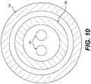
- Figure 10 is a cross sectional view of the delivery device along section DD in Figure 8 .
- the at least one suture 120 extends through the draw bar tube 304, which extends through the tubular shaft 204.
- Figure 11 is a cross sectional view of the delivery device along section EE in Figure 8 .
- the at least one suture 120 and the draw bar 305 extend through the draw bar tube 304.
- Figure 12 illustrates the suture anchor delivery device 200 and suture anchor 100 inserted in a bone prior to deployment.
- a hole H is drilled into the patient's bone.
- the delivery device 200, with the anchor 100 mounted thereon, are inserted through the hole through a patient's tissue T, through an outer layer of cortical bone CO and then into an inner layer of cancellous bone CA.
- the at least one suture 120 is woven through the anchor 100.
- the draw bar 305 is positioned at an end 304a of the draw bar tube 304 and extends outwardly therefrom through the shaft tip 206.
- the draw bar 305 extends outwardly from the shaft tip 206 and the anchor 100 is mounted on the draw bar 305.
- the draw bar 305 is integrally formed with the draw bar tube 304.
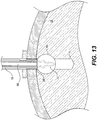
- Figure 13 illustrates the suture anchor delivery device 200 and suture anchor 100 inserted in the bone after deployment.
- the anchor 100 is pulled up by the at least one suture 120 and is collapsed. As the anchor 100 collapses it compresses into the side of the bone CA creating a ball-like shape.
- the draw bar 305 is retracted at the same time the suture 120 is retracted by the draw bar assembly 300.
- the shaft tip 206 prevents the anchor 100 from coming out of the bone CA during the process.
- the trigger 208 When the trigger 208 is squeezed, a force is applied against the draw bar housing 302 to push the draw bar assembly 300 back through the opening 202c of the housing portion 202. As the draw bar assembly 300 is actuated the draw bar 305 is pulled back through the shaft tip 206. With the draw bar 305, the at least one suture 120, which is wrapped around the cut out portion 316 is also pulled back. The pulling back of the at least one suture 120 collapses the anchor 100.
- Figure 14 illustrates the suture anchor 100 and suture 120 having been fixed in the tissue.
- the delivery device 200 is removed from the hole H, leaving only the anchor 100 and the suture 120.
- the suture 120 is released (i.e., unraveled) from the draw bar assembly 300.
- the delivery device 200 is then removed from the hole H and the suture 120 is removed from the delivery device.
- the suture 120 is then tightened and knotted to close the tissue.
- the locking knot 124 prevents the suture(s) from relaxing, which would cause the device to straighten, particularly following the deployment phase and before the suture is knotted to close the tissue. The only way to otherwise prevent this would be to apply constant tension to the suture during this interim period, which could last several minutes if not longer.
- the feature of the locking knot is important for maintaining the stability of the device after deployment.
Landscapes
- Health & Medical Sciences (AREA)
- Life Sciences & Earth Sciences (AREA)
- Surgery (AREA)
- Veterinary Medicine (AREA)
- General Health & Medical Sciences (AREA)
- Animal Behavior & Ethology (AREA)
- Public Health (AREA)
- Engineering & Computer Science (AREA)
- Biomedical Technology (AREA)
- Heart & Thoracic Surgery (AREA)
- Nuclear Medicine, Radiotherapy & Molecular Imaging (AREA)
- Medical Informatics (AREA)
- Molecular Biology (AREA)
- Rheumatology (AREA)
- Oral & Maxillofacial Surgery (AREA)
- Vascular Medicine (AREA)
- Transplantation (AREA)
- Cardiology (AREA)
- Rehabilitation Therapy (AREA)
- Orthopedic Medicine & Surgery (AREA)
- Surgical Instruments (AREA)
Abstract
Description
- The present invention relates to a soft tissue repair device and more particularly to a bone anchor made of only suture material.
- Sutures and suture/bone anchors are used for repairing tissue in surgical procedures to secure soft tissue to bone. Specifically, tears in soft tissues such as cartilage, ligament or muscle can be repaired by suturing. Suture anchors are commonly used during the surgical procedure to provide an attachment location for the suture. The suture anchor may be secured into a bone by inserting the anchor into a pre-formed hole in the bone. Typical suture anchors are made from metallic or polymer materials.
- For example,
U.S. Patent Application Publication No. 2013/0018416 describes a soft suture anchor manufactured from a single, continuous length of suture. The suture includes braided (i.e., multifilament) suture and monofilament suture, as well as metallic or non-metallic filament material. - Furthermore,
U.S. Patent No. 8,273,106 discloses a soft tissue repair device that includes a deformable tubular member having a longitudinal bore extending between first and second ends, and a flexible strand passing through the longitudinal bore of the tubular member. The flexible strand has a first end portion extending outside the first open end and a second portion forming a first loop that passes through the second open end and an intermediate opening between the first and second open ends. Pulling the first end portion of the flexible strand away from the tubular member deforms a portion of the tubular member between the second open end and the intermediate opening into a folded shape forming a soft tissue anchor. - Additionally,
U.S. Patent No. 8,361,113 discloses a method and apparatus for repairing a tear in soft tissue. The method includes positioning a plurality of collapsible tubes around a suture. The collapsible tubes are pushed through soft tissue and orthopedic mesh on opposite sides of a tear in soft tissue. When tension is applied to the suture, the tubes are compressed, which fixes the suture to the soft tissue. The collapsible tubes (anchors) are made from biocompatible materials (e.g., polymers, woven textile, etc.). - In another example,
U.S. Patent No. 8,652,172 discloses an anchor for securing tissue that includes flexible tubular members and a suture member. The anchor is made from biocompatible materials including, for example, polyester, polyethylene, polypropylene, cotton, silk, etc. - Moreover,
U.S. Patent No. 8,795,334 discloses an apparatus including a flexible fixation member and a suture interwoven through a plurality of openings in the fixation member. The fixation member is made from tape, mesh, tube or other malleable or flexible structures. - Finally,
U.S. Patent No. 8,986,327 discloses an assembly including a flexible fixation member, a suture and a delivery device. The flexible fixation member is a flexible or malleable tube and the suture is woven through the fixation member. - Conventional bone anchors, like those described above, involve a foreign material other than the suture that is left behind in the bone. These foreign materials can cause foreign body reactions. Furthermore, if the bone anchor becomes loose and moves into a joint, the bone anchor can cause damage to articular cartilage. Thus, the inventors have discovered that that there is a need for re-attaching soft tissue back to a bone without any materials other than the suture material.
- In view of the foregoing and other exemplary problems, drawbacks, and disadvantages of the conventional methods and structures, an exemplary feature of the present invention is to provide an all-suture based anchor to reattach soft tissue back to bone without any other materials besides suture material.
- According to an exemplary embodiment of the invention, a suture anchor includes a tubular anchor body made of suture material, the tubular anchor body having a distal tip and a bore extending through the tubular anchor body to a proximal end of the tubular anchor body and a suture woven from the distal tip and extending through the bore and exiting through the proximal end. The tubular anchor body is configured such that pulling an end of the suture at the proximal end causes the tubular anchor body to become compressed.
- According to an exemplary embodiment a suture anchor consists of or is only formed of or is formed primarily of a tubular anchor body made of suture material, the tubular anchor body having a distal tip and a bore extending through the tubular anchor body to a proximal end of the tubular anchor body and a suture woven from the distal tip and extending through the bore and exiting through the proximal end.
- According to an exemplary embodiment, a suture anchor delivery device includes a handle assembly and a draw bar assembly. The handle assembly includes a handle portion, a trigger, pivotably attached to the handle portion and a tubular shaft extending through the handle assembly. The draw bar assembly is retractably disposed within the handle assembly. The draw bar assembly includes a draw bar tube extending through the tubular shaft, the draw bar tube having a channel disposed through the draw bar tube configured to receive a suture, a draw bar housing disposed at a first end of the tubular shaft, the draw bar housing having a cutout configured to receive an end of the suture such that the end of the suture wraps around the cutout and a draw bar disposed within the draw bar tube and configured to receive a suture anchor mounted on a tip of the draw bar. Upon actuating the trigger the draw bar assembly is retracted.
- According to an exemplary embodiment, a suture delivery system includes a suture anchor, a suture and a delivery device. The suture anchor has a tubular anchor body made of suture material, the tubular anchor body having a distal tip and a bore extending through the tubular anchor body to a proximal end of the tubular anchor body. The suture is woven from the distal tip and extends through the bore and exiting through the proximal end. The delivery device includes a handle assembly and a draw bar assembly. The handle assembly includes a handle portion, a trigger, pivotably attached to the handle portion and a tubular shaft extending through the handle assembly. The draw bar assembly is retractably disposed within the handle assembly. The draw bar assembly includes a draw bar tube extending through the tubular shaft, the draw bar tube having a channel disposed through the draw bar tube configured to receive the suture, a draw bar housing disposed at a first end of the tubular shaft, the draw bar housing having a cutout configured to receive an end of the suture such that the end of the suture wraps around the cutout and a draw bar disposed within the draw bar tube and configured to receive a suture anchor mounted on a tip of the draw bar. Upon actuating the trigger the draw bar assembly is retracted.
- The suture-based anchor described above includes a column of suture material with an interwoven smaller suture or sutures to collapse the anchor when the suture is pulled upon. Accordingly, with the anchor described above, no foreign material other than the suture is left behind in the bone.
- Further scope of applicability of the present invention will become apparent from the detailed description given hereinafter. However, it should be understood that the detailed description and specific examples, while indicating preferred embodiments of the invention, are given by way of illustration only, since various changes and modifications within the spirit and scope of the invention will become apparent to those skilled in the art from this detailed description.
- The present invention will become more fully understood from the detailed description given herein below and the accompanying drawings which are given by way of illustration only, and thus, do not limit the present invention, and wherein:
-
Figure 1 illustrates a perspective view of asuture anchor 100 according to an exemplary embodiment of the invention; -
Figure 2 illustrates a suture anchor delivery device according to an exemplary embodiment of the invention; -
Figure 3 illustrates the suture anchor delivery device illustrated with a cover thereof removed; -
Figure 4 illustrates an exploded view of the suture anchor delivery device; -
Figure 5 illustrates adrive rod assembly 300 of the suture anchor delivery device; -
Figure 6 illustrates atrigger 208 of the suture anchor delivery device; -
Figure 7 illustrates a cross sectional view of thehousing portion 202 of the suture anchor delivery device; -
Figure 8 illustrates thedelivery device 200 with theanchor 100 mounted thereon; -
Figure 9 illustrates a cross sectional view of an end of the suture anchor delivery device along section CC fromFigure 8 ; -
Figure 10 is a cross sectional view of the delivery device along section DD inFigure 8 ; -
Figure 11 is a cross sectional view of the delivery device along section EE inFigure 8 ; -
Figure 12 illustrates the suture anchor delivery device and suture anchor inserted in a bone prior to deployment; -
Figure 13 illustrates the suture anchor delivery device and suture anchor inserted in a bone after deployment; and -
Figure 14 illustrates the suture anchor and suture having been fixed in the tissue. - Referring now to the drawings, and more particularly to
Figures 1-14 , there are shown exemplary embodiments of the method and structures according to the present invention. -
Figure 1 illustrates an all suture basedanchor 100 according to certain exemplary embodiments of the present invention. According to an exemplary embodiment of the present invention, the suture basedanchor 100 is made entirely of suture material. As is illustrated inFigure 1 , the suture basedanchor 100 includes acolumn 102 made from woven suture material. Thecolumn 102 has an at least partially closed,distal end 104 at one end of the column. A column-shapedbore 106 extends through thecolumn 102 of theanchor 100. Thebore 106 forms anopening 108 at aproximal end 110 of thecolumn 102. - The
anchor 100 also includes at least onesuture 120 woven into theanchor 100.Figure 1 illustrates asingle suture 120; however, any number of additional sutures may be woven into theanchor 100. As illustrated inFigure 1 , thesuture 120 is woven from thedistal end 104, through thebore 106 and exits throug theopening 108 in the proximal end of thecolumn 102. Aloop 122 of suture is formed outside of thedistal end 104 of the anchor. Thesuture loop 122 acts as sling or stop to prevent the suture from pulling thru thedistal end 104. This in turn allows thecolumn 100 to collapse when pulled taut. Addtionally, as an alternative to theloop 122, knots can be disposed on both ends of thesutures 120. In certain exemplary embodiments of the invention, more than onesuture 120 is woven through thebore 106. If more than onesuture 120 is provided, then a corresponding number ofsuture loops 122 will be formed outside of thedistal end 104 of theanchor 100. Finally, a slidingknot 124 is tied an end of the suture. The slidingknot 124 provides friction to prevent thesutures 120 from backing out when the sutures are pulled taut. Thus, the slidingknot 124 prevents the sutures from loosening from the collapsed state, which would cause the anchor construct to straighten and possibly pull out of the hole. Accordingly, theentire anchor 100 is composed of only suture material. Thus, with the all suture basedanchor 100, according to certain exemplary embodiments of the present invention, no foreign material other than the suture is left behind in the bone. -
Figure 2 illustrates a sutureanchor delivery device 200 according to an exemplary embodiment of the invention. Thedelivery device 200 includes a housing (handle)portion 202 and an elongate,tubular shaft 204 extending outwardly from thehousing portion 202. Ashaft tip 206 is disposed at a distal end of theelongate shaft 202. -
Figure 3 illustrates an enlarged version of the sutureanchor delivery device 200 illustrated inFigure 2 with a cover thereof removed to more clearly illustrate individual components of thedelivery device 200. The delivery device includes atrigger 208, which is pivotably mounted to thehousing portion 202. Thetrigger 208 is configured to receive a squeezing force from a user of thedelivery device 200 to move thetrigger 208 from a first position to a second position in which thedelivery device 200 is actuated, with respect to a fixedhandle 202a. The elongate,tubular shaft 204 extends from afront end 202b of thehousing portion 202. Thehousing portion 202, theshaft 204 and thetrigger 208 make up a handle assembly of the delivery device. - Furthermore, the delivery device includes a
draw bar assembly 300 mounted at a rear side of thehousing portion 202 adjacent thehandle 202a, which is opposite to thefront end 202b of thehousing portion 202 from which theshaft 204 extends. Thedraw bar assembly 300 includes adraw bar housing 302 and adraw bar tube 304 extending from thedraw bar housing 302, through thehousing portion 202 and through theshaft 204. Thedraw bar tube 304 is a hollow, tubular-shaped member. Thedraw bar assembly 300 also includes adraw bar 305 disposed within thedraw bar tube 304. As is shown inFigure 2 , a tip of thedraw bar 305, in an initial pre-deployment position of thedelivery device 200, extends outward from theshaft tip 206. Thedraw bar 305 is configured to receive and support asuture anchor 100 mounted thereon. -
Figure 4 illustrates an exploded view of thedelivery device 200 as illustrated inFigure 3 . The individual components discussed with respect toFigure 3 are more clearly illustrated in the exploded view ofFigure 4 . -
Figure 5 illustrates thedraw bar assembly 300 in further detail. Thedraw bar housing 302 is a generally column-shaped member having thedraw bar tube 304 extending outwardly therefrom. Thedraw bar assembly 300 is moveably mounted within thehousing portion 202 of the delivery device such that thedraw bar assembly 300 is linearly retractable from its initial position (seeFigure 3 described above) in thehousing portion 202. An elongatedflat portion 306 extends along a bottom of thedraw bar housing 302. Theflat portion 306 is provided for orientation of thedraw bar housing 302 within thehousing portion 202. Furthermore, alocking tab 308 is disposed along the bottom of thedraw bar housing 302 at anend 310 of thedraw bar housing 302 from which thedraw bar tube 304 extends. Thelocking tab 308 acts as a stop and prevents full withdrawal of thedraw bar assembly 300 from thehousing portion 202. A vertically disposedflange portion 312 is disposed at arear end 314 of thedraw bar housing 302. An undercutportion 316 is formed within theflange portion 312. The undercutportion 316 is configured to receive an end of the at least onesuture 120. The at least onesuture 120 extends through thedraw bar tube 304, throughdraw bar housing 304 and is then wrapped around the undercutportion 312. If necessary, an optional O-ring may be used to hold the at least onesuture 120 in place around the undercutportion 316. -
Figure 6 illustrates thetrigger 208 of thedelivery device 200. Thetrigger 208 includes apivot hole 210 through atop end 212 of thetrigger 208. Thepivot hole 210 is configured to receive a pivot pin 214 (seeFigure 7 ) to pivotably mount thetrigger 208 to thehousing portion 202. Thetrigger 208 also includes acutout 216 extending longitudinally through thetrigger 208. Thecutout 216 is configured to receive thedraw bar tube 304, such that thedraw bar tube 304 passes through thetrigger 208. -
Figure 7 illustrates a cross sectional view of thehousing portion 202 of the sutureanchor delivery device 200. As discussed above, thetrigger 208 is pivotably attached to thehousing portion 202 by thepivot pin 214. Thedraw bar assembly 300 extends through anopening 202a in thehousing portion 202. Thetrigger 208 is movable with respect to the fixedhandle 202a. Thedraw bar housing 302 extends through thehandle 202a. Afirst end 304a of thedraw bar tube 304 is mounted within thedraw bar housing 302. Thedraw bar tube 304 extends out from theend 310 of thedraw bar housing 302 and extends through thecutout 216 into theshaft 204, which is mounted within afront end 202b of thehousing portion 202. Thedraw bar housing 302 has a suture thru channel 318 disposed therethrough. The at least onesuture 120 extends through the channel 318 and is then wound around the undercutportion 316. When thetrigger 208 is squeezed, a force is applied against thedraw bar housing 302 to push thedraw bar assembly 300 back through theopening 202c of thehousing portion 202. As thedraw bar assembly 300 is actuated thedraw bar 305 is pulled back through theshaft tip 206. With thedraw bar 305, the at least onesuture 120, which is wrapped around the cut outportion 316 is also pulled back. Thestop 308 prevents thedraw bar assembly 300 from being removed entirely from thehousing portion 202. -
Figure 8 illustrates thedelivery device 200 with theanchor 100 mounted on the end of thedraw bar 305. Thedelivery device 200 and anchor are illustrated inFigure 8 in the initial position prior to the deployment of theanchor 100. -
Figure 9 is a cross sectional view of the delivery device along section CC inFigure 8 . Thesuture 120 is disposed within theshaft tip 206. Thedraw bar 305 of thedraw bar tube 304 is disposed between the two ends of thesuture 120. Extra space is provided within theshaft tip 206 in the event additional sutures are provided. Furthermore,Figure 10 is a cross sectional view of the delivery device along section DD inFigure 8 . The at least onesuture 120 extends through thedraw bar tube 304, which extends through thetubular shaft 204. Still further,Figure 11 is a cross sectional view of the delivery device along section EE inFigure 8 . The at least onesuture 120 and thedraw bar 305 extend through thedraw bar tube 304. -
Figure 12 illustrates the sutureanchor delivery device 200 andsuture anchor 100 inserted in a bone prior to deployment. During use, a hole H is drilled into the patient's bone. Thedelivery device 200, with theanchor 100 mounted thereon, are inserted through the hole through a patient's tissue T, through an outer layer of cortical bone CO and then into an inner layer of cancellous bone CA. The at least onesuture 120 is woven through theanchor 100. As is illustrated inFigure 12 , thedraw bar 305 is positioned at anend 304a of thedraw bar tube 304 and extends outwardly therefrom through theshaft tip 206. Thedraw bar 305 extends outwardly from theshaft tip 206 and theanchor 100 is mounted on thedraw bar 305. According to an exemplary aspect of the invention, thedraw bar 305 is integrally formed with thedraw bar tube 304. -
Figure 13 illustrates the sutureanchor delivery device 200 andsuture anchor 100 inserted in the bone after deployment. Once thedelivery device 200 is actuated, theanchor 100 is pulled up by the at least onesuture 120 and is collapsed. As theanchor 100 collapses it compresses into the side of the bone CA creating a ball-like shape. Thedraw bar 305 is retracted at the same time thesuture 120 is retracted by thedraw bar assembly 300. Theshaft tip 206 prevents theanchor 100 from coming out of the bone CA during the process. - When the
trigger 208 is squeezed, a force is applied against thedraw bar housing 302 to push thedraw bar assembly 300 back through theopening 202c of thehousing portion 202. As thedraw bar assembly 300 is actuated thedraw bar 305 is pulled back through theshaft tip 206. With thedraw bar 305, the at least onesuture 120, which is wrapped around the cut outportion 316 is also pulled back. The pulling back of the at least onesuture 120 collapses theanchor 100. -
Figure 14 illustrates thesuture anchor 100 andsuture 120 having been fixed in the tissue. InFigure 14 , thedelivery device 200 is removed from the hole H, leaving only theanchor 100 and thesuture 120. Once thedelivery device 200 is fully deployed with theanchor 100 in the drill hole H, thesuture 120 is released (i.e., unraveled) from thedraw bar assembly 300. Thedelivery device 200 is then removed from the hole H and thesuture 120 is removed from the delivery device. Thesuture 120 is then tightened and knotted to close the tissue. With the claimed invention, since theanchor 100 itself is made entirely of suture material, only suture material remains in the bone and tissue. - As detailed above, the locking
knot 124 prevents the suture(s) from relaxing, which would cause the device to straighten, particularly following the deployment phase and before the suture is knotted to close the tissue. The only way to otherwise prevent this would be to apply constant tension to the suture during this interim period, which could last several minutes if not longer. Thus, the feature of the locking knot is important for maintaining the stability of the device after deployment. - The invention being thus described, it will be obvious that the same may be varied in many ways. Such variations are not to be regarded as a departure from the spirit and scope of the invention, and all such modifications as would be obvious to one skilled in the art are to be included within the scope of the following claims.
Claims (14)
- A suture anchor, comprising or consisting of:a tubular anchor body made of suture material, the tubular anchor body having a distal tip and a bore (106) extending through the tubular anchor body to a proximal end of the tubular anchor body; anda suture (120) woven from the distal tip and extending through the bore (106) and exiting through the proximal end.
- The suture anchor according to claim 1, wherein the tubular anchor body is configured such that pulling an end of the suture (120) at the proximal end causes the tubular anchor body to become compressed.
- The suture anchor according to claim 1 or 2, wherein the tubular anchor body is made entirely of suture material.
- The suture anchor according to any one of claims 1-3, wherein the tubular anchor body consists of suture material.
- The suture anchor according to any one of claims 1-4, wherein the suture forms a suture loop (122) outside of the distal tip.
- The suture anchor according to any one of claims 1-5, wherein a plurality of sutures (120) is woven from the distal tip and extending through the bore (106) and exiting through the proximal end.
- The suture anchor according to claim 6, wherein each of the plurality of sutures (120) forms a suture loop (122) outside of the distal tip.
- The suture anchor according to any one of claims 1-7, wherein an entirety of the suture anchor (100) is made of only suture material.
- A suture anchor delivery device, comprising:a handle assembly, comprising:a handle portion;a trigger (208), pivotably attached to the handle portion; anda tubular shaft (204) extending from a front end of the handle portion; anda draw bar assembly retractably disposed within the handle assembly, the draw bar assembly comprising:a draw bar tube (304) extending through the tubular shaft (204), the draw bar tube (304) having a channel disposed through the draw bar tube (304) configured to receive a suture (120);a draw bar housing (302) disposed at a first end of the draw bar tube (304), the draw bar housing (302) having a cutout configured to receive an end of the suture (120) such that the end of the suture (120) wraps around the cutout; anda draw bar (305) disposed within the draw bar tube (304) and configured to receive a suture anchor (100) mounted on a tip of the draw bar (305),wherein upon actuating the trigger (208) the draw bar assembly is retracted.
- The suture anchor delivery device according to claim 9, wherein the draw bar assembly further comprises a flat portion (306) extending along a bottom of the draw bar housing (302) for orienting the draw bar housing (302) within the handle portion.
- The suture anchor delivery device according to claim 9 or 10, wherein the draw bar assembly further comprises a stop member configured to prevent the draw bar assembly from being completely removed from the handle portion.
- The suture anchor delivery device according to any one of claims 9-11, wherein the suture anchor delivery device is configured for delivering the suture anchor according to any one of claims 1-8.
- A suture delivery system, comprising:a suture anchor (100) having a tubular anchor body made of suture material, the tubular anchor body having a distal tip and a bore (106) extending through the tubular anchor body to a proximal end of the tubular anchor body;a suture (120) woven from the distal tip and extending through the bore (106) and exiting through the proximal end; anda delivery device, comprising:a handle assembly, comprising:a handle portion;a trigger (208), pivotably attached to the handle portion; anda tubular shaft (204) extending from a front end of the handle portion;a draw bar assembly retractably disposed within the handle assembly, the draw bar assembly comprising:a draw bar tube (304) extending through the tubular shaft (204), the draw bar tube (304) having a channel disposed through the draw bar tube (304) configured to receive the suture (120);a draw bar housing (302) disposed at a first end of the draw bar tube (304), the draw bar housing (302) having a cutout configured to receive an end of the suture (120) such that the end of the suture (120) wraps around the cutout; anda draw bar (305) disposed within the draw bar tube (304) and configured to receive the suture anchor (100) mounted on a tip of the draw bar (305),wherein upon actuating the trigger (208) the draw bar assembly is retracted.
- The suture delivery system according to claim 13, wherein the suture anchor (100) and the suture (120) are configured according to any one of claims 1-8 and wherein the delivery device is the suture anchor delivery device according to any one of claims 9-12.
Applications Claiming Priority (1)
| Application Number | Priority Date | Filing Date | Title |
|---|---|---|---|
| US15/603,770 US10631847B2 (en) | 2017-05-24 | 2017-05-24 | Bone anchor including only suture material and delivery device thereof |
Publications (3)
| Publication Number | Publication Date |
|---|---|
| EP3406201A2 true EP3406201A2 (en) | 2018-11-28 |
| EP3406201A3 EP3406201A3 (en) | 2019-02-27 |
| EP3406201B1 EP3406201B1 (en) | 2020-09-09 |
Family
ID=62186219
Family Applications (1)
| Application Number | Title | Priority Date | Filing Date |
|---|---|---|---|
| EP18000458.2A Active EP3406201B1 (en) | 2017-05-24 | 2018-05-15 | Delivery device for bone anchor including only suture material |
Country Status (2)
| Country | Link |
|---|---|
| US (1) | US10631847B2 (en) |
| EP (1) | EP3406201B1 (en) |
Families Citing this family (1)
| Publication number | Priority date | Publication date | Assignee | Title |
|---|---|---|---|---|
| CN114366204B (en) * | 2022-01-13 | 2022-12-30 | 北京天星博迈迪医疗器械有限公司 | Full suture anchor and implantation equipment |
Citations (6)
| Publication number | Priority date | Publication date | Assignee | Title |
|---|---|---|---|---|
| US8273106B2 (en) | 2006-02-03 | 2012-09-25 | Biomet Sports Medicine, Llc | Soft tissue repair and conduit device |
| US20130018416A1 (en) | 2011-04-15 | 2013-01-17 | Linvatec Corporation | Soft suture anchor made of braided or monofilament suture |
| US8361113B2 (en) | 2006-02-03 | 2013-01-29 | Biomet Sports Medicine, Llc | Method and apparatus for coupling soft tissue to a bone |
| US8652172B2 (en) | 2006-02-03 | 2014-02-18 | Biomet Sports Medicine, Llc | Flexible anchors for tissue fixation |
| US8795334B2 (en) | 2011-01-28 | 2014-08-05 | Smith & Nephew, Inc. | Tissue repair |
| US8986327B2 (en) | 2012-10-18 | 2015-03-24 | Smith & Nephew, Inc. | Flexible anchor delivery system |
Family Cites Families (22)
| Publication number | Priority date | Publication date | Assignee | Title |
|---|---|---|---|---|
| US3123077A (en) | 1964-03-03 | Surgical suture | ||
| US4738255A (en) * | 1986-04-07 | 1988-04-19 | Biotron Labs, Inc. | Suture anchor system |
| WO2003088846A1 (en) | 2002-04-22 | 2003-10-30 | Tyco Healthcare Group, Lp | Tack and tack applier |
| US20100204791A1 (en) | 2002-06-11 | 2010-08-12 | Orbix Medical Ltd. | System for lifting and reshaping soft tissue |
| US8298262B2 (en) * | 2006-02-03 | 2012-10-30 | Biomet Sports Medicine, Llc | Method for tissue fixation |
| US8562647B2 (en) | 2006-09-29 | 2013-10-22 | Biomet Sports Medicine, Llc | Method and apparatus for securing soft tissue to bone |
| US20090248071A1 (en) | 2008-03-07 | 2009-10-01 | Alure Medical , Inc. | Minimally invasive tissue support |
| US8496684B2 (en) | 2007-10-31 | 2013-07-30 | Ethicon Endo-Surgery, Inc. | Method for deploying a device for gastric volume reduction |
| US7819298B2 (en) | 2008-02-14 | 2010-10-26 | Ethicon Endo-Surgery, Inc. | Surgical stapling apparatus with control features operable with one hand |
| US20110082471A1 (en) | 2009-10-06 | 2011-04-07 | Holcomb Matthew D | Reloadable Laparoscopic Fastener Deploying Device |
| FR2965168A1 (en) | 2010-09-23 | 2012-03-30 | Tornier Inc | SUTURE IMPLANT COMPONENT AND SUTURE IMPLANT DEVICE COMPRISING SUCH COMPONENT |
| US8936614B2 (en) | 2010-12-30 | 2015-01-20 | Covidien Lp | Combined unilateral/bilateral jaws on a surgical instrument |
| US9421008B2 (en) | 2011-09-23 | 2016-08-23 | Arthrex, Inc. | Soft suture-based anchors |
| US9962149B2 (en) | 2011-11-14 | 2018-05-08 | Arthrocare Corporation | Tissue repair assembly |
| JP6157503B2 (en) | 2012-04-23 | 2017-07-05 | ミニンヴェイシヴ リミティッド | Arthroscopic surgical device |
| US9463011B2 (en) | 2012-08-17 | 2016-10-11 | Arthrex, Inc. | Soft anchors with soft eyelets |
| US9320512B2 (en) | 2012-08-17 | 2016-04-26 | Arthrex, Inc. | Self-cinching soft anchors |
| US9782250B2 (en) | 2014-03-03 | 2017-10-10 | Tenjin LLC | Implant placement systems and one-handed methods for tissue fixation using same |
| US10039543B2 (en) | 2014-08-22 | 2018-08-07 | Biomet Sports Medicine, Llc | Non-sliding soft anchor |
| WO2016089396A1 (en) | 2014-12-03 | 2016-06-09 | Smith & Nephew, Inc. | Sock anchor and method |
| US20160157844A1 (en) | 2014-12-03 | 2016-06-09 | Smith & Nephew, Inc. | Sock anchor and method |
| US9512388B2 (en) | 2015-02-18 | 2016-12-06 | Henkel Ag & Co. Kgaa | Solid state detergent in a transparent container |
-
2017
- 2017-05-24 US US15/603,770 patent/US10631847B2/en active Active
-
2018
- 2018-05-15 EP EP18000458.2A patent/EP3406201B1/en active Active
Patent Citations (6)
| Publication number | Priority date | Publication date | Assignee | Title |
|---|---|---|---|---|
| US8273106B2 (en) | 2006-02-03 | 2012-09-25 | Biomet Sports Medicine, Llc | Soft tissue repair and conduit device |
| US8361113B2 (en) | 2006-02-03 | 2013-01-29 | Biomet Sports Medicine, Llc | Method and apparatus for coupling soft tissue to a bone |
| US8652172B2 (en) | 2006-02-03 | 2014-02-18 | Biomet Sports Medicine, Llc | Flexible anchors for tissue fixation |
| US8795334B2 (en) | 2011-01-28 | 2014-08-05 | Smith & Nephew, Inc. | Tissue repair |
| US20130018416A1 (en) | 2011-04-15 | 2013-01-17 | Linvatec Corporation | Soft suture anchor made of braided or monofilament suture |
| US8986327B2 (en) | 2012-10-18 | 2015-03-24 | Smith & Nephew, Inc. | Flexible anchor delivery system |
Also Published As
| Publication number | Publication date |
|---|---|
| US20180338754A1 (en) | 2018-11-29 |
| EP3406201B1 (en) | 2020-09-09 |
| US10631847B2 (en) | 2020-04-28 |
| EP3406201A3 (en) | 2019-02-27 |
Similar Documents
| Publication | Publication Date | Title |
|---|---|---|
| US11896210B2 (en) | Method and apparatus for coupling soft tissue to a bone | |
| US12023019B2 (en) | Tissue repair assembly and system with soft anchoring implant | |
| US12256921B2 (en) | Knotless all suture tissue repair | |
| US20220133296A1 (en) | Method for tissue fixation | |
| US11311287B2 (en) | Method for tissue fixation | |
| JP2019536518A5 (en) | ||
| US20180125638A1 (en) | Flexible implant with adjustable coils | |
| US12453546B2 (en) | Knotless soft anchor system | |
| JP2012501757A (en) | Knotless suture anchor | |
| US20240108328A1 (en) | Method for tissue fixation | |
| AU2024200311B2 (en) | Suture anchor construct and deployment device | |
| EP4096530B1 (en) | Knotless soft tissue implant systems | |
| US20170172561A1 (en) | Hybrid suture anchor | |
| US20260026798A1 (en) | Knotless soft anchor system | |
| EP3406201B1 (en) | Delivery device for bone anchor including only suture material | |
| US20210346148A1 (en) | Suture construct and method of tissue fixation | |
| US20160157844A1 (en) | Sock anchor and method |
Legal Events
| Date | Code | Title | Description |
|---|---|---|---|
| PUAI | Public reference made under article 153(3) epc to a published international application that has entered the european phase |
Free format text: ORIGINAL CODE: 0009012 |
|
| STAA | Information on the status of an ep patent application or granted ep patent |
Free format text: STATUS: THE APPLICATION HAS BEEN PUBLISHED |
|
| AK | Designated contracting states |
Kind code of ref document: A2 Designated state(s): AL AT BE BG CH CY CZ DE DK EE ES FI FR GB GR HR HU IE IS IT LI LT LU LV MC MK MT NL NO PL PT RO RS SE SI SK SM TR |
|
| AX | Request for extension of the european patent |
Extension state: BA ME |
|
| PUAL | Search report despatched |
Free format text: ORIGINAL CODE: 0009013 |
|
| AK | Designated contracting states |
Kind code of ref document: A3 Designated state(s): AL AT BE BG CH CY CZ DE DK EE ES FI FR GB GR HR HU IE IS IT LI LT LU LV MC MK MT NL NO PL PT RO RS SE SI SK SM TR |
|
| AX | Request for extension of the european patent |
Extension state: BA ME |
|
| RIC1 | Information provided on ipc code assigned before grant |
Ipc: A61B 17/06 20060101ALI20190122BHEP Ipc: A61B 17/04 20060101AFI20190122BHEP |
|
| RAP1 | Party data changed (applicant data changed or rights of an application transferred) |
Owner name: KARL STORZ SE & CO. KG |
|
| STAA | Information on the status of an ep patent application or granted ep patent |
Free format text: STATUS: REQUEST FOR EXAMINATION WAS MADE |
|
| 17P | Request for examination filed |
Effective date: 20190628 |
|
| RBV | Designated contracting states (corrected) |
Designated state(s): AL AT BE BG CH CY CZ DE DK EE ES FI FR GB GR HR HU IE IS IT LI LT LU LV MC MK MT NL NO PL PT RO RS SE SI SK SM TR |
|
| GRAP | Despatch of communication of intention to grant a patent |
Free format text: ORIGINAL CODE: EPIDOSNIGR1 |
|
| STAA | Information on the status of an ep patent application or granted ep patent |
Free format text: STATUS: GRANT OF PATENT IS INTENDED |
|
| GRAJ | Information related to disapproval of communication of intention to grant by the applicant or resumption of examination proceedings by the epo deleted |
Free format text: ORIGINAL CODE: EPIDOSDIGR1 |
|
| STAA | Information on the status of an ep patent application or granted ep patent |
Free format text: STATUS: REQUEST FOR EXAMINATION WAS MADE |
|
| INTG | Intention to grant announced |
Effective date: 20200313 |
|
| INTC | Intention to grant announced (deleted) | ||
| GRAP | Despatch of communication of intention to grant a patent |
Free format text: ORIGINAL CODE: EPIDOSNIGR1 |
|
| STAA | Information on the status of an ep patent application or granted ep patent |
Free format text: STATUS: GRANT OF PATENT IS INTENDED |
|
| INTG | Intention to grant announced |
Effective date: 20200507 |
|
| GRAS | Grant fee paid |
Free format text: ORIGINAL CODE: EPIDOSNIGR3 |
|
| GRAA | (expected) grant |
Free format text: ORIGINAL CODE: 0009210 |
|
| STAA | Information on the status of an ep patent application or granted ep patent |
Free format text: STATUS: THE PATENT HAS BEEN GRANTED |
|
| AK | Designated contracting states |
Kind code of ref document: B1 Designated state(s): AL AT BE BG CH CY CZ DE DK EE ES FI FR GB GR HR HU IE IS IT LI LT LU LV MC MK MT NL NO PL PT RO RS SE SI SK SM TR |
|
| REG | Reference to a national code |
Ref country code: GB Ref legal event code: FG4D |
|
| REG | Reference to a national code |
Ref country code: AT Ref legal event code: REF Ref document number: 1310565 Country of ref document: AT Kind code of ref document: T Effective date: 20200915 Ref country code: CH Ref legal event code: EP |
|
| REG | Reference to a national code |
Ref country code: IE Ref legal event code: FG4D |
|
| REG | Reference to a national code |
Ref country code: DE Ref legal event code: R096 Ref document number: 602018007470 Country of ref document: DE |
|
| REG | Reference to a national code |
Ref country code: LT Ref legal event code: MG4D |
|
| PG25 | Lapsed in a contracting state [announced via postgrant information from national office to epo] |
Ref country code: HR Free format text: LAPSE BECAUSE OF FAILURE TO SUBMIT A TRANSLATION OF THE DESCRIPTION OR TO PAY THE FEE WITHIN THE PRESCRIBED TIME-LIMIT Effective date: 20200909 Ref country code: BG Free format text: LAPSE BECAUSE OF FAILURE TO SUBMIT A TRANSLATION OF THE DESCRIPTION OR TO PAY THE FEE WITHIN THE PRESCRIBED TIME-LIMIT Effective date: 20201209 Ref country code: GR Free format text: LAPSE BECAUSE OF FAILURE TO SUBMIT A TRANSLATION OF THE DESCRIPTION OR TO PAY THE FEE WITHIN THE PRESCRIBED TIME-LIMIT Effective date: 20201210 Ref country code: LT Free format text: LAPSE BECAUSE OF FAILURE TO SUBMIT A TRANSLATION OF THE DESCRIPTION OR TO PAY THE FEE WITHIN THE PRESCRIBED TIME-LIMIT Effective date: 20200909 Ref country code: SE Free format text: LAPSE BECAUSE OF FAILURE TO SUBMIT A TRANSLATION OF THE DESCRIPTION OR TO PAY THE FEE WITHIN THE PRESCRIBED TIME-LIMIT Effective date: 20200909 Ref country code: NO Free format text: LAPSE BECAUSE OF FAILURE TO SUBMIT A TRANSLATION OF THE DESCRIPTION OR TO PAY THE FEE WITHIN THE PRESCRIBED TIME-LIMIT Effective date: 20201209 Ref country code: FI Free format text: LAPSE BECAUSE OF FAILURE TO SUBMIT A TRANSLATION OF THE DESCRIPTION OR TO PAY THE FEE WITHIN THE PRESCRIBED TIME-LIMIT Effective date: 20200909 |
|
| REG | Reference to a national code |
Ref country code: AT Ref legal event code: MK05 Ref document number: 1310565 Country of ref document: AT Kind code of ref document: T Effective date: 20200909 |
|
| REG | Reference to a national code |
Ref country code: NL Ref legal event code: MP Effective date: 20200909 |
|
| PG25 | Lapsed in a contracting state [announced via postgrant information from national office to epo] |
Ref country code: PL Free format text: LAPSE BECAUSE OF FAILURE TO SUBMIT A TRANSLATION OF THE DESCRIPTION OR TO PAY THE FEE WITHIN THE PRESCRIBED TIME-LIMIT Effective date: 20200909 Ref country code: RS Free format text: LAPSE BECAUSE OF FAILURE TO SUBMIT A TRANSLATION OF THE DESCRIPTION OR TO PAY THE FEE WITHIN THE PRESCRIBED TIME-LIMIT Effective date: 20200909 Ref country code: LV Free format text: LAPSE BECAUSE OF FAILURE TO SUBMIT A TRANSLATION OF THE DESCRIPTION OR TO PAY THE FEE WITHIN THE PRESCRIBED TIME-LIMIT Effective date: 20200909 |
|
| PG25 | Lapsed in a contracting state [announced via postgrant information from national office to epo] |
Ref country code: EE Free format text: LAPSE BECAUSE OF FAILURE TO SUBMIT A TRANSLATION OF THE DESCRIPTION OR TO PAY THE FEE WITHIN THE PRESCRIBED TIME-LIMIT Effective date: 20200909 Ref country code: RO Free format text: LAPSE BECAUSE OF FAILURE TO SUBMIT A TRANSLATION OF THE DESCRIPTION OR TO PAY THE FEE WITHIN THE PRESCRIBED TIME-LIMIT Effective date: 20200909 Ref country code: PT Free format text: LAPSE BECAUSE OF FAILURE TO SUBMIT A TRANSLATION OF THE DESCRIPTION OR TO PAY THE FEE WITHIN THE PRESCRIBED TIME-LIMIT Effective date: 20210111 Ref country code: CZ Free format text: LAPSE BECAUSE OF FAILURE TO SUBMIT A TRANSLATION OF THE DESCRIPTION OR TO PAY THE FEE WITHIN THE PRESCRIBED TIME-LIMIT Effective date: 20200909 Ref country code: SM Free format text: LAPSE BECAUSE OF FAILURE TO SUBMIT A TRANSLATION OF THE DESCRIPTION OR TO PAY THE FEE WITHIN THE PRESCRIBED TIME-LIMIT Effective date: 20200909 |
|
| PG25 | Lapsed in a contracting state [announced via postgrant information from national office to epo] |
Ref country code: AT Free format text: LAPSE BECAUSE OF FAILURE TO SUBMIT A TRANSLATION OF THE DESCRIPTION OR TO PAY THE FEE WITHIN THE PRESCRIBED TIME-LIMIT Effective date: 20200909 Ref country code: AL Free format text: LAPSE BECAUSE OF FAILURE TO SUBMIT A TRANSLATION OF THE DESCRIPTION OR TO PAY THE FEE WITHIN THE PRESCRIBED TIME-LIMIT Effective date: 20200909 Ref country code: ES Free format text: LAPSE BECAUSE OF FAILURE TO SUBMIT A TRANSLATION OF THE DESCRIPTION OR TO PAY THE FEE WITHIN THE PRESCRIBED TIME-LIMIT Effective date: 20200909 Ref country code: IS Free format text: LAPSE BECAUSE OF FAILURE TO SUBMIT A TRANSLATION OF THE DESCRIPTION OR TO PAY THE FEE WITHIN THE PRESCRIBED TIME-LIMIT Effective date: 20210109 |
|
| REG | Reference to a national code |
Ref country code: DE Ref legal event code: R097 Ref document number: 602018007470 Country of ref document: DE |
|
| PG25 | Lapsed in a contracting state [announced via postgrant information from national office to epo] |
Ref country code: SK Free format text: LAPSE BECAUSE OF FAILURE TO SUBMIT A TRANSLATION OF THE DESCRIPTION OR TO PAY THE FEE WITHIN THE PRESCRIBED TIME-LIMIT Effective date: 20200909 |
|
| PLBE | No opposition filed within time limit |
Free format text: ORIGINAL CODE: 0009261 |
|
| STAA | Information on the status of an ep patent application or granted ep patent |
Free format text: STATUS: NO OPPOSITION FILED WITHIN TIME LIMIT |
|
| 26N | No opposition filed |
Effective date: 20210610 |
|
| PG25 | Lapsed in a contracting state [announced via postgrant information from national office to epo] |
Ref country code: DK Free format text: LAPSE BECAUSE OF FAILURE TO SUBMIT A TRANSLATION OF THE DESCRIPTION OR TO PAY THE FEE WITHIN THE PRESCRIBED TIME-LIMIT Effective date: 20200909 Ref country code: SI Free format text: LAPSE BECAUSE OF FAILURE TO SUBMIT A TRANSLATION OF THE DESCRIPTION OR TO PAY THE FEE WITHIN THE PRESCRIBED TIME-LIMIT Effective date: 20200909 |
|
| REG | Reference to a national code |
Ref country code: CH Ref legal event code: PL |
|
| PG25 | Lapsed in a contracting state [announced via postgrant information from national office to epo] |
Ref country code: CH Free format text: LAPSE BECAUSE OF NON-PAYMENT OF DUE FEES Effective date: 20210531 Ref country code: MC Free format text: LAPSE BECAUSE OF FAILURE TO SUBMIT A TRANSLATION OF THE DESCRIPTION OR TO PAY THE FEE WITHIN THE PRESCRIBED TIME-LIMIT Effective date: 20200909 Ref country code: LI Free format text: LAPSE BECAUSE OF NON-PAYMENT OF DUE FEES Effective date: 20210531 Ref country code: LU Free format text: LAPSE BECAUSE OF NON-PAYMENT OF DUE FEES Effective date: 20210515 |
|
| REG | Reference to a national code |
Ref country code: BE Ref legal event code: MM Effective date: 20210531 |
|
| PG25 | Lapsed in a contracting state [announced via postgrant information from national office to epo] |
Ref country code: IE Free format text: LAPSE BECAUSE OF NON-PAYMENT OF DUE FEES Effective date: 20210515 |
|
| PG25 | Lapsed in a contracting state [announced via postgrant information from national office to epo] |
Ref country code: BE Free format text: LAPSE BECAUSE OF NON-PAYMENT OF DUE FEES Effective date: 20210531 |
|
| PG25 | Lapsed in a contracting state [announced via postgrant information from national office to epo] |
Ref country code: NL Free format text: LAPSE BECAUSE OF NON-PAYMENT OF DUE FEES Effective date: 20200923 Ref country code: CY Free format text: LAPSE BECAUSE OF FAILURE TO SUBMIT A TRANSLATION OF THE DESCRIPTION OR TO PAY THE FEE WITHIN THE PRESCRIBED TIME-LIMIT Effective date: 20200909 |
|
| P01 | Opt-out of the competence of the unified patent court (upc) registered |
Effective date: 20230527 |
|
| PG25 | Lapsed in a contracting state [announced via postgrant information from national office to epo] |
Ref country code: HU Free format text: LAPSE BECAUSE OF FAILURE TO SUBMIT A TRANSLATION OF THE DESCRIPTION OR TO PAY THE FEE WITHIN THE PRESCRIBED TIME-LIMIT; INVALID AB INITIO Effective date: 20180515 |
|
| PG25 | Lapsed in a contracting state [announced via postgrant information from national office to epo] |
Ref country code: MK Free format text: LAPSE BECAUSE OF FAILURE TO SUBMIT A TRANSLATION OF THE DESCRIPTION OR TO PAY THE FEE WITHIN THE PRESCRIBED TIME-LIMIT Effective date: 20200909 |
|
| PG25 | Lapsed in a contracting state [announced via postgrant information from national office to epo] |
Ref country code: MT Free format text: LAPSE BECAUSE OF FAILURE TO SUBMIT A TRANSLATION OF THE DESCRIPTION OR TO PAY THE FEE WITHIN THE PRESCRIBED TIME-LIMIT Effective date: 20200909 |
|
| PGFP | Annual fee paid to national office [announced via postgrant information from national office to epo] |
Ref country code: DE Payment date: 20250528 Year of fee payment: 8 |
|
| PGFP | Annual fee paid to national office [announced via postgrant information from national office to epo] |
Ref country code: IT Payment date: 20250522 Year of fee payment: 8 |
|
| PGFP | Annual fee paid to national office [announced via postgrant information from national office to epo] |
Ref country code: FR Payment date: 20250526 Year of fee payment: 8 |
|
| PG25 | Lapsed in a contracting state [announced via postgrant information from national office to epo] |
Ref country code: TR Free format text: LAPSE BECAUSE OF FAILURE TO SUBMIT A TRANSLATION OF THE DESCRIPTION OR TO PAY THE FEE WITHIN THE PRESCRIBED TIME-LIMIT Effective date: 20200909 |
|
| PGFP | Annual fee paid to national office [announced via postgrant information from national office to epo] |
Ref country code: GB Payment date: 20260313 Year of fee payment: 9 |