EP3406197B1 - Rotary joint having a capacitive data link with modular support - Google Patents
Rotary joint having a capacitive data link with modular support Download PDFInfo
- Publication number
- EP3406197B1 EP3406197B1 EP18173635.6A EP18173635A EP3406197B1 EP 3406197 B1 EP3406197 B1 EP 3406197B1 EP 18173635 A EP18173635 A EP 18173635A EP 3406197 B1 EP3406197 B1 EP 3406197B1
- Authority
- EP
- European Patent Office
- Prior art keywords
- stationary
- rotatable
- coupler
- rotary joint
- transmitter
- Prior art date
- Legal status (The legal status is an assumption and is not a legal conclusion. Google has not performed a legal analysis and makes no representation as to the accuracy of the status listed.)
- Active
Links
Images




Classifications
-
- A—HUMAN NECESSITIES
- A61—MEDICAL OR VETERINARY SCIENCE; HYGIENE
- A61B—DIAGNOSIS; SURGERY; IDENTIFICATION
- A61B6/00—Apparatus or devices for radiation diagnosis; Apparatus or devices for radiation diagnosis combined with radiation therapy equipment
- A61B6/56—Details of data transmission or power supply, e.g. use of slip rings
-
- A—HUMAN NECESSITIES
- A61—MEDICAL OR VETERINARY SCIENCE; HYGIENE
- A61B—DIAGNOSIS; SURGERY; IDENTIFICATION
- A61B6/00—Apparatus or devices for radiation diagnosis; Apparatus or devices for radiation diagnosis combined with radiation therapy equipment
- A61B6/02—Arrangements for diagnosis sequentially in different planes; Stereoscopic radiation diagnosis
- A61B6/03—Computed tomography [CT]
- A61B6/032—Transmission computed tomography [CT]
-
- A—HUMAN NECESSITIES
- A61—MEDICAL OR VETERINARY SCIENCE; HYGIENE
- A61B—DIAGNOSIS; SURGERY; IDENTIFICATION
- A61B6/00—Apparatus or devices for radiation diagnosis; Apparatus or devices for radiation diagnosis combined with radiation therapy equipment
- A61B6/02—Arrangements for diagnosis sequentially in different planes; Stereoscopic radiation diagnosis
- A61B6/03—Computed tomography [CT]
- A61B6/032—Transmission computed tomography [CT]
- A61B6/035—Mechanical aspects of CT
-
- H—ELECTRICITY
- H01—ELECTRIC ELEMENTS
- H01R—ELECTRICALLY-CONDUCTIVE CONNECTIONS; STRUCTURAL ASSOCIATIONS OF A PLURALITY OF MUTUALLY-INSULATED ELECTRICAL CONNECTING ELEMENTS; COUPLING DEVICES; CURRENT COLLECTORS
- H01R39/00—Rotary current collectors, distributors or interrupters
- H01R39/02—Details for dynamo electric machines
- H01R39/08—Slip-rings
-
- H—ELECTRICITY
- H04—ELECTRIC COMMUNICATION TECHNIQUE
- H04B—TRANSMISSION
- H04B5/00—Near-field transmission systems, e.g. inductive or capacitive transmission systems
- H04B5/20—Near-field transmission systems, e.g. inductive or capacitive transmission systems characterised by the transmission technique; characterised by the transmission medium
- H04B5/22—Capacitive coupling
-
- H—ELECTRICITY
- H04—ELECTRIC COMMUNICATION TECHNIQUE
- H04B—TRANSMISSION
- H04B5/00—Near-field transmission systems, e.g. inductive or capacitive transmission systems
- H04B5/70—Near-field transmission systems, e.g. inductive or capacitive transmission systems specially adapted for specific purposes
- H04B5/79—Near-field transmission systems, e.g. inductive or capacitive transmission systems specially adapted for specific purposes for data transfer in combination with power transfer
Definitions
- couplers for capacitive coupling. It is preferred, if these couplers have pairs of couplers comprising a transmitter coupler and a receiver coupler.
- the transmitter coupler is a line or a strip line along the way of movement between the couplers. Specifically for rotatable movement this means that the transmitter coupler is arranged in a circular shape around the center axis of rotation.
- the receiver coupler may either by a line, a strip line or a simple capacitive coupling pad, which are preferably terminated with the characteristic impedance, to achieve a capacitive coupling to the transmitter coupler.
- the at least one rotatable transmitter coupler and/or the at least one stationary transmitter coupler may be in a radial distance less than 10 mm, preferably less than 5 mm, and most preferably less than 3 mm from the facing at least one stationary receiver coupler and/or the at least one rotatable receiver coupler.
- the stationary carrier comprises sheet metal
- it can be manufactured easily. This may for example be done by cutting a rectangular sheet of metal or plastic material having the right size, whereas the length corresponds to the circumference of the later arc-shape, and the width corresponds to the height.
- the sheet metal or plastic material gets its required stiffness and/or stability when it is mounted to the stationary base.
- at least one stationary transmitter coupler may be attached, for example by the use of a double-sided adhesive tape.
- the sheet is a plane sheet, this may easily be done on a plane work bench. It is not necessary to handle a complex circular structure.
Landscapes
- Engineering & Computer Science (AREA)
- Health & Medical Sciences (AREA)
- Life Sciences & Earth Sciences (AREA)
- Medical Informatics (AREA)
- Computer Networks & Wireless Communication (AREA)
- Biomedical Technology (AREA)
- Molecular Biology (AREA)
- Biophysics (AREA)
- Nuclear Medicine, Radiotherapy & Molecular Imaging (AREA)
- Optics & Photonics (AREA)
- Pathology (AREA)
- Radiology & Medical Imaging (AREA)
- Physics & Mathematics (AREA)
- Heart & Thoracic Surgery (AREA)
- High Energy & Nuclear Physics (AREA)
- Surgery (AREA)
- Animal Behavior & Ethology (AREA)
- General Health & Medical Sciences (AREA)
- Public Health (AREA)
- Veterinary Medicine (AREA)
- Signal Processing (AREA)
- Pulmonology (AREA)
- Theoretical Computer Science (AREA)
- Apparatus For Radiation Diagnosis (AREA)
- Waveguide Connection Structure (AREA)
Description
- The invention relates to sliprings and contactless data links as may be used in Computed Tomography (CT) scanners.
- In computed tomography (CT) scanners, usually large sliprings having a diameter of approximately 1 meter or more are required. The sliding tracks must be held at a supporting structure while insulating the sliding tracks from each other and from other machine parts. Furthermore, capacitive data links for coupling data with high data rates from a rotating part to a stationary part are provided.
-
US 5,054,189 discloses a slipring having a body of insulating material with pre-machined grooves into which a conductive sliding track is rolled. -
US 5,734,218 discloses a drum-shaped slipring having a pre-formed insulating body with grooves into which sliding tracks are pressed. The body needs a rigid backing member as mechanical support. - A capacitive rotary joint for CT scanners is disclosed in
US 5,600,697 . A large diameter rotating ring carries a differentially driven strip coupler guiding a signal along this circumference of the ring. At the stationary side, there is a capacitive coupler picking up the signal from the near field of the strip coupler. The receiving coupler comprises two couplers held orthogonally to the transmission coupler. To obtain a sufficient coupling efficiency and therefore a sufficient signal level at the receiver, the coupler must be mounted in close proximity to the strip coupler. - A bidirectional capacitive coupler is disclosed in
US 2013/0214614 . Here, the channels for the communication from the rotating to the stationary side and vice versa are interleaved. The datalink transmitters are mounted on a comparatively large, solid and therefore expensive body of insulating material. - These embodiments have the disadvantage that they require comparatively solid insulating bodies which further require a significant amount of insulating material or additional rigid backing. Another disadvantage is the comparatively big size of the insulating body which makes handling and manufacturing of the insulating body difficult and expensive.
- An arrangement for transmitting electrical signals and/or energy between parts that can be rotated in relation to each other is disclosed in
US 6,798,309 B2 . - The problem to be solved by the invention is to provide a rotary joint component or slipring component having a capacitive data link in a comparatively lightweight and simple assembly.
- Solutions of the problem are described in the independent claims. The dependent claims relate to further improvements of the invention.
- A rotary joint component comprises a stationary part and a rotatable part. The rotatable part is rotatable against the stationary part. In a CT (computed tomography) scanner a gantry has a rotatable part which rotates around the patient. The rotatable part requires a power supply from the stationary part which is delivered by the rotary joint. The rotary joint further delivers data from the rotatable part to the stationary part. Therefore, the direction of a preferred data link is from the rotatable to the stationary part. In an alternate embodiment, there may be a data transfer from the stationary to the rotatable part, or in both directions. A data transfer in both directions may provide a data flow from an image detector of the rotatable gantry to a stationary part, and of control data from the stationary part to the rotatable part of the gantry.
- In an embodiment, the rotatable part comprises a rotatable base for holding rotatable components, like at least one rotatable receiver coupler. The stationary part comprises a stationary base which holds at least one stationary transmitter coupler. The positions of the stationary transmitter coupler and the rotatable receiver coupler are adjusted such that the stationary transmitter coupler is capacitively coupled to the at least one rotatable receiver coupler, such that data may be transferred capacitively.
- Herein, reference is simply made to a general coupler for capacitive coupling. It is preferred, if these couplers have pairs of couplers comprising a transmitter coupler and a receiver coupler. Most preferably, the transmitter coupler is a line or a strip line along the way of movement between the couplers. Specifically for rotatable movement this means that the transmitter coupler is arranged in a circular shape around the center axis of rotation. The receiver coupler may either by a line, a strip line or a simple capacitive coupling pad, which are preferably terminated with the characteristic impedance, to achieve a capacitive coupling to the transmitter coupler.
- The at least one rotatable transmitter coupler and/or the at least one stationary transmitter coupler may be in a radial distance less than 10 mm, preferably less than 5 mm, and most preferably less than 3 mm from the facing at least one stationary receiver coupler and/or the at least one rotatable receiver coupler.
- It is obvious that further components are required for a capacitive data transfer, like a data transmitter which preferably is at the rotatable part, and a data receiver which preferably is at the stationary part. These components are not part of the invention. The invention primarily relates to mechanical components and the basic coupling components for capacitive data coupling as well as mechanical slipring components.
- The stationary transmitter coupler is mounted to or held by a stationary carrier. This stationary carrier comprises a circular-shaped sheet metal or plastic which is further held by the stationary base. The sheet may have a thickness between 0.2mm and 3mm. A metal sheet may have a thickness between 0.3mm and 1.5mm whereas a plastic sheet may have a thickness between 1.5mm and 3mm. A metal sheet material may comprise at least one of steel, stainless steel, brass, copper or any combination thereof. A plastic sheet material may comprise Polycarbonate, Polyethylene or any other suitable material with or without fiber reinforcement.
- As the stationary carrier comprises sheet metal, it can be manufactured easily. This may for example be done by cutting a rectangular sheet of metal or plastic material having the right size, whereas the length corresponds to the circumference of the later arc-shape, and the width corresponds to the height. The sheet metal or plastic material gets its required stiffness and/or stability when it is mounted to the stationary base. To this sheet, at least one stationary transmitter coupler may be attached, for example by the use of a double-sided adhesive tape. As the sheet is a plane sheet, this may easily be done on a plane work bench. It is not necessary to handle a complex circular structure.
- The stationary base may have means for holding the stationary carrier comprising sheet metal or plastic in a circular shape. Preferably, the stationary carrier may be fixed to the stationary base by screws, bolts or similar means. It may be glued, injected-molded or held otherwise to the stationary base. The stationary carrier may be press fitted into a groove in the stationary base, it may be bolted or screwed to the inner or outer diameter of a rotating base. Handling of two separate components, like the stationary carrier and the stationary base is comparatively simple, because both are flat components. As such, they may be shipped easily and assembled later at their final destination. This design also offers a larger flexibility. For example, different coupler configurations may be preassembled on stationary carriers and before finishing the slipring, one of these stationary carriers may be selected to assemble the desired configuration.
- Making the stationary carrier of sheet metal also provides an electrical and/or electromagnetic shielding to the data link and specifically to the transmitter coupler. A shield may also be provided, if a plastic sheet material is used, which has a metallized surface. Alternatively an aluminium-plastic composite material may be cut as rectangular sheet and bent into a circular shape for use as carrier.
- The at least one rotatable receiver coupler and/or the at least one stationary receiver coupler may be galvanically connected to its stationary carrier which further may be galvanically connected to its stationary base.
- There may be at least one sliding track at the rotatable part. Such sliding tracks may be used for galvanic contact together with sliding brushes to provide a galvanic connection between the stationary and the rotatable part. Such a galvanic connection may be used for supplying electrical power from the stationary to the rotatable part.
- At the stationary base, there may be a stationary electronic module support for supporting and holding a stationary electronic module. Such a stationary electronic module may provide connecting means, like connectors and/or amplifiers and/or transmitters and/or receivers, which may be connected to at least one stationary transmitter line and/or a stationary receiver line.
- Furthermore, the stationary part may provide connecting means, like connectors and/or amplifiers and/or transmitters and/or receivers, which may be connected to at least one stationary transmitter line and/or a stationary receiver line. The rotatable electronic module and/or the stationary electronic module may also be connected to at least one of the sliding tracks. Such a connection may be used for grounding and/or for supplying power or other signals to the electronic modules.
- In the following the invention will be described by way of example, without limitation of the general inventive concept, on examples of embodiment with reference to the drawings.
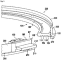
- Figure 1
- shows a first embodiment of the invention.
- Figure 2
- shows the rotatable part without stationary part.
- Figure 3
- shows the stationary part from the inner side.
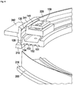
- Figure 4
- shows further details.
- Figure 5
- shows a full view.
- Figure 6
- shows a detail of a stationary carrier mounted to a stationary base
- In
Figure 1 , a first embodiment of the invention is shown. It is obvious that the invention relates to a circular embodiment of the basic components. In this Figure and in some of the following Figures, a section is cut out of the ring-shaped parts to show their inner structure. Arotatable part 100 comprises arotatable base 110 which may support arotatable transmitter coupler 120 which may be a strip line. The rotatable base further may support a plurality of slidingtracks electronic module 150 which may be mounted to a rotatableelectronic module support 141. For mounting the rotatable part for example to a rotatable part of a CT scanner, there may be a plurality of rotatable screw holes 180. - This figure also shows a
stationary part 200 which has astationary base 210 holding astationary carrier 260. On thisstationary carrier 260, there is astationary transmitter coupler 220 which may be a transmission line. There may also be a stationaryelectronic module 250 which may be supported by or mounted to a stationary electronic module support which may comprise afirst support component 241 and asecond support component 242. For mounting the stationary part for example to a stationary part of a CT scanner, there may be a plurality of stationary screw holes 280. - In
Figure 2 , therotatable part 100 is shown withoutstationary part 200. Here, more details of therotatable transmitter coupler 120, which may be mounted in a groove, are shown. Furthermore, therotatable receiver coupler 130 is shown, which preferably is held by the rotatableelectronic module support 141. - In
Figure 3 , thestationary part 200 is shown from the inner side. Here, thestationary receiver coupler 230 is shown, which may be held by the stationaryelectronic module support stationary carrier 260 depends on the number of data transmission links and typically is in the range of 20mm to 100mm. - In
Figure 4 , further details are shown, specifically showing the interaction between thestationary transmitter coupler 220 and therotatable receiver coupler 130 which basically runs on the same track, such that they are always in a close distance, which may be below 10 mm, more preferably below 5 mm, and most preferably below 3 mm. - In
Figure 5 , a full view of therotatable part 100 and thestationary part 200 is shown, with all associated components is shown. The axis ofrotation 190 passes through the center at a right angle through a plane defined by therotatable base 110. - In
Figure 6 , details of the mounting of the stationary carrier into the stationary base are given. Preferably, thestationary base 210 has aslot 211 for holding thestationary carrier 260. -
- 100
- rotatable part
- 110
- rotatable base
- 120
- rotatable transmitter coupler
- 130
- rotatable receiver coupler
- 141
- rotatable electronic module support
- 150
- rotatable electronic module
- 151, 152, 153, 154
- sliding tracks
- 180
- rotatable screw hole
- 190
- axis of rotation
- 200
- stationary part
- 210
- stationary base
- 211
- slot
- 220
- stationary transmitter coupler
- 230
- stationary receiver coupler
- 241, 242
- stationary electronic module support
- 250
- stationary electronic module
- 260
- stationary carrier
- 280
- stationary screw hole
Claims (8)
- Rotary joint component comprising a rotatable part (100) and a stationary part (200) stationary against the rotatable part (100),
the rotatable part (100) comprising a rotatable base (110) holding at least one rotatable receiver coupler (130),
the stationary part (200) comprising a stationary base (210) holding at least one stationary transmitter coupler (220), wherein the at least one stationary transmitter coupler (220) is capacitively coupled to the at least one rotatable receiver coupler (130),
characterized in, that
the stationary transmitter coupler (220) is mounted to a stationary carrier (260) which comprises circular shaped sheet metal which is further held by the stationary base (210), wherein
the stationary carrier (260) is held within a slot or groove (211) of the stationary base (210), and
the stationary carrier (260) comprises circular shaped sheet metal which has ends connected to each other. - Rotary joint component according to claim 1,
characterized in, that
the rotatable part (100) comprises at least one sliding track (151, 152, 153, 154) held by the rotatable base (110). - Rotary joint component according to any of the preceding claims,
characterized in, that
the rotatable part (100) holds at least one rotatable transmitter coupler (120) and the stationary part (200) holds at least one stationary receiver coupler (230) which is capacitively coupled to the at least one rotatable transmitter coupler (120). - Rotary joint component according to any of the preceding claims,
characterized in, that
the at least one rotatable transmitter coupler (120) and/or the at least one stationary transmitter coupler (220) are lines or striplines which are preferably terminated with their characteristic impedance. - Rotary joint component according to any of the preceding claims,
characterized in, that
the at least one rotatable receiver coupler (130) and/or the at least one stationary receiver coupler (230) are lines, striplines or pads which are preferably terminated with their characteristic impedance. - Rotary joint component according to any of the preceding claims,
characterized in, that
the at least one rotatable transmitter coupler (120) and/or the at least one stationary transmitter coupler (220) are in a distance less than 10mm, preferably 5mm and most preferably 3mm from the at least one rotatable receiver coupler (130) and/or the at least one stationary receiver coupler (230). - Rotary joint component according to any of the preceding claims,
characterized in, that
the at least one rotatable receiver coupler (130) and/or the at least one stationary receiver coupler (230) is galvanically connected to its stationary carrier which is galvanically connected to its stationary base. - Rotary joint component according to any of the preceding claims,
characterized in, that
the stationary carrier (260) comprises circular shaped sheet metal which has ends connected to each other by soldering or welding.
Applications Claiming Priority (1)
| Application Number | Priority Date | Filing Date | Title |
|---|---|---|---|
| EP17172301 | 2017-05-22 |
Publications (2)
| Publication Number | Publication Date |
|---|---|
| EP3406197A1 EP3406197A1 (en) | 2018-11-28 |
| EP3406197B1 true EP3406197B1 (en) | 2019-08-07 |
Family
ID=59061783
Family Applications (1)
| Application Number | Title | Priority Date | Filing Date |
|---|---|---|---|
| EP18173635.6A Active EP3406197B1 (en) | 2017-05-22 | 2018-05-22 | Rotary joint having a capacitive data link with modular support |
Country Status (3)
| Country | Link |
|---|---|
| US (2) | US10433808B2 (en) |
| EP (1) | EP3406197B1 (en) |
| CN (1) | CN108926354B (en) |
Families Citing this family (3)
| Publication number | Priority date | Publication date | Assignee | Title |
|---|---|---|---|---|
| US10433808B2 (en) | 2017-05-22 | 2019-10-08 | Schleifring Gmbh | Rotary joint having a capacitive data link with modular support |
| CA3203581A1 (en) | 2020-12-15 | 2022-06-23 | Husqvarna Ab | Snow removal device with continuously rotatable discharge chute |
| CN119051680A (en) | 2024-08-21 | 2024-11-29 | 上海联影医疗科技股份有限公司 | Rotating assembly of data link and electronic computer tomography equipment |
Family Cites Families (13)
| Publication number | Priority date | Publication date | Assignee | Title |
|---|---|---|---|---|
| US5054189A (en) | 1990-10-25 | 1991-10-08 | Litton Systetms, Inc. | Method of manufacturing an electrical slip ring assembly |
| US5600697A (en) | 1995-03-20 | 1997-02-04 | General Electric Company | Transmission line using a power combiner for high data rate communication in a computerized tomography system |
| US5734218A (en) | 1996-05-13 | 1998-03-31 | Litton Systems, Inc. | Electrical slip ring and method of manufacturing same |
| EP1234388B1 (en) | 1999-11-30 | 2004-03-03 | Schleifring und Apparatebau GmbH | Arrangement for transmitting electrical signals and/or energy between parts that can be rotated in relation to each other |
| US7344500B2 (en) * | 2004-07-27 | 2008-03-18 | Medtronic Minimed, Inc. | Sensing system with auxiliary display |
| US7466791B2 (en) * | 2005-05-12 | 2008-12-16 | Schleifring Und Apparatebau Gmbh | Data transmission system for computer tomographs |
| DE102007021597A1 (en) * | 2007-05-08 | 2008-11-20 | Siemens Ag | Arrangement and method for contactless transmission of electrical signals between two units |
| KR20090003878A (en) * | 2007-07-05 | 2009-01-12 | 삼성전자주식회사 | Battery charging device and method for mobile terminal using UBS device |
| DE102007048164B4 (en) * | 2007-10-08 | 2013-01-17 | Siemens Aktiengesellschaft | A method for contactless transmission of at least one differential signal between a transmitter and a receiver in the presence of at least one common mode noise signal and associated circuitry |
| EP2621341B1 (en) * | 2010-09-28 | 2017-04-26 | Schleifring und Apparatebau GmbH | Contactless rotary joint |
| EP3018842B1 (en) | 2014-11-04 | 2017-03-22 | Schleifring und Apparatebau GmbH | Method and device for the adjustment of contactless data links |
| EP3046267A1 (en) * | 2015-01-15 | 2016-07-20 | Schleifring und Apparatebau GmbH | Receiving coupler for contactless data link |
| US10433808B2 (en) | 2017-05-22 | 2019-10-08 | Schleifring Gmbh | Rotary joint having a capacitive data link with modular support |
-
2018
- 2018-05-21 US US15/985,407 patent/US10433808B2/en active Active
- 2018-05-22 EP EP18173635.6A patent/EP3406197B1/en active Active
- 2018-05-22 CN CN201810494714.0A patent/CN108926354B/en active Active
-
2019
- 2019-08-23 US US16/549,104 patent/US10702236B2/en active Active
Non-Patent Citations (1)
| Title |
|---|
| None * |
Also Published As
| Publication number | Publication date |
|---|---|
| EP3406197A1 (en) | 2018-11-28 |
| US10702236B2 (en) | 2020-07-07 |
| CN108926354B (en) | 2020-08-14 |
| CN108926354A (en) | 2018-12-04 |
| US20180333130A1 (en) | 2018-11-22 |
| US20190374192A1 (en) | 2019-12-12 |
| US10433808B2 (en) | 2019-10-08 |
Similar Documents
| Publication | Publication Date | Title |
|---|---|---|
| US10702236B2 (en) | Rotary joint having a capacitive data link with modular support | |
| JP6161212B2 (en) | Waveguide structure for non-contact connectors | |
| JP5752936B2 (en) | Transmission line applied to non-contact slip ring | |
| EP2270919B1 (en) | Broadband high-frequency slip ring system | |
| US5805115A (en) | Rotary microwave antenna system | |
| CN209929452U (en) | Double-channel microwave rotary joint | |
| US11962053B2 (en) | Rotary joint with dielectric waveguide | |
| CN105812028B (en) | Receiving coupler for contactless data link | |
| EP1729646B1 (en) | Rotary transmitter comprising a dielectric waveguide | |
| JP4450822B2 (en) | Microwave transmission equipment | |
| EP1748523A2 (en) | Broadband high frequency slip-ring system | |
| US8731348B2 (en) | Capacitive rotary joint for optical signals | |
| US6985046B2 (en) | Device for the transmission of electric signals between at least two units mobile relative to each other | |
| JP2001044715A (en) | Signal transmission board and signal transmission device | |
| CN216501542U (en) | Plate roller signal module power supply and information transmission configuration structure | |
| CN114601485B (en) | EMV shielding for contactless data transmission | |
| CN112583126B (en) | Nested wireless energy signal synchronous transmission device with slip ring | |
| JP2016039443A (en) | Radio communication device | |
| JP7577488B2 (en) | Communication Equipment | |
| US10608701B2 (en) | Splittable rotary joint module with contactless data link | |
| EP4700977A1 (en) | Rotary assembly for therapeutic device and computed tomography device | |
| GB2509129A (en) | Rotating high-frequency electrical connector | |
| EP3879624A1 (en) | Stripline connections | |
| CN117393967A (en) | Column type multichannel medium-frequency rotary transmission device | |
| JP2021188733A (en) | Thrust bearing |
Legal Events
| Date | Code | Title | Description |
|---|---|---|---|
| PUAI | Public reference made under article 153(3) epc to a published international application that has entered the european phase |
Free format text: ORIGINAL CODE: 0009012 |
|
| STAA | Information on the status of an ep patent application or granted ep patent |
Free format text: STATUS: THE APPLICATION HAS BEEN PUBLISHED |
|
| STAA | Information on the status of an ep patent application or granted ep patent |
Free format text: STATUS: REQUEST FOR EXAMINATION WAS MADE |
|
| AK | Designated contracting states |
Kind code of ref document: A1 Designated state(s): AL AT BE BG CH CY CZ DE DK EE ES FI FR GB GR HR HU IE IS IT LI LT LU LV MC MK MT NL NO PL PT RO RS SE SI SK SM TR |
|
| AX | Request for extension of the european patent |
Extension state: BA ME |
|
| 17P | Request for examination filed |
Effective date: 20181105 |
|
| REG | Reference to a national code |
Ref country code: DE Ref legal event code: R079 Ref document number: 602018000375 Country of ref document: DE Free format text: PREVIOUS MAIN CLASS: A61B0006030000 Ipc: H01R0039080000 |
|
| RBV | Designated contracting states (corrected) |
Designated state(s): AL AT BE BG CH CY CZ DE DK EE ES FI FR GB GR HR HU IE IS IT LI LT LU LV MC MK MT NL NO PL PT RO RS SE SI SK SM TR |
|
| GRAP | Despatch of communication of intention to grant a patent |
Free format text: ORIGINAL CODE: EPIDOSNIGR1 |
|
| STAA | Information on the status of an ep patent application or granted ep patent |
Free format text: STATUS: GRANT OF PATENT IS INTENDED |
|
| RIC1 | Information provided on ipc code assigned before grant |
Ipc: H04B 5/00 20060101ALI20190118BHEP Ipc: A61B 6/00 20060101ALI20190118BHEP Ipc: H01R 39/08 20060101AFI20190118BHEP Ipc: A61B 6/03 20060101ALI20190118BHEP |
|
| INTG | Intention to grant announced |
Effective date: 20190215 |
|
| GRAS | Grant fee paid |
Free format text: ORIGINAL CODE: EPIDOSNIGR3 |
|
| GRAA | (expected) grant |
Free format text: ORIGINAL CODE: 0009210 |
|
| STAA | Information on the status of an ep patent application or granted ep patent |
Free format text: STATUS: THE PATENT HAS BEEN GRANTED |
|
| AK | Designated contracting states |
Kind code of ref document: B1 Designated state(s): AL AT BE BG CH CY CZ DE DK EE ES FI FR GB GR HR HU IE IS IT LI LT LU LV MC MK MT NL NO PL PT RO RS SE SI SK SM TR |
|
| REG | Reference to a national code |
Ref country code: GB Ref legal event code: FG4D |
|
| REG | Reference to a national code |
Ref country code: CH Ref legal event code: EP Ref country code: AT Ref legal event code: REF Ref document number: 1165272 Country of ref document: AT Kind code of ref document: T Effective date: 20190815 |
|
| REG | Reference to a national code |
Ref country code: DE Ref legal event code: R096 Ref document number: 602018000375 Country of ref document: DE |
|
| REG | Reference to a national code |
Ref country code: IE Ref legal event code: FG4D |
|
| REG | Reference to a national code |
Ref country code: NL Ref legal event code: MP Effective date: 20190807 |
|
| REG | Reference to a national code |
Ref country code: LT Ref legal event code: MG4D |
|
| PG25 | Lapsed in a contracting state [announced via postgrant information from national office to epo] |
Ref country code: BG Free format text: LAPSE BECAUSE OF FAILURE TO SUBMIT A TRANSLATION OF THE DESCRIPTION OR TO PAY THE FEE WITHIN THE PRESCRIBED TIME-LIMIT Effective date: 20191107 Ref country code: NO Free format text: LAPSE BECAUSE OF FAILURE TO SUBMIT A TRANSLATION OF THE DESCRIPTION OR TO PAY THE FEE WITHIN THE PRESCRIBED TIME-LIMIT Effective date: 20191107 Ref country code: NL Free format text: LAPSE BECAUSE OF FAILURE TO SUBMIT A TRANSLATION OF THE DESCRIPTION OR TO PAY THE FEE WITHIN THE PRESCRIBED TIME-LIMIT Effective date: 20190807 Ref country code: LT Free format text: LAPSE BECAUSE OF FAILURE TO SUBMIT A TRANSLATION OF THE DESCRIPTION OR TO PAY THE FEE WITHIN THE PRESCRIBED TIME-LIMIT Effective date: 20190807 Ref country code: FI Free format text: LAPSE BECAUSE OF FAILURE TO SUBMIT A TRANSLATION OF THE DESCRIPTION OR TO PAY THE FEE WITHIN THE PRESCRIBED TIME-LIMIT Effective date: 20190807 Ref country code: SE Free format text: LAPSE BECAUSE OF FAILURE TO SUBMIT A TRANSLATION OF THE DESCRIPTION OR TO PAY THE FEE WITHIN THE PRESCRIBED TIME-LIMIT Effective date: 20190807 Ref country code: PT Free format text: LAPSE BECAUSE OF FAILURE TO SUBMIT A TRANSLATION OF THE DESCRIPTION OR TO PAY THE FEE WITHIN THE PRESCRIBED TIME-LIMIT Effective date: 20191209 Ref country code: HR Free format text: LAPSE BECAUSE OF FAILURE TO SUBMIT A TRANSLATION OF THE DESCRIPTION OR TO PAY THE FEE WITHIN THE PRESCRIBED TIME-LIMIT Effective date: 20190807 |
|
| REG | Reference to a national code |
Ref country code: AT Ref legal event code: MK05 Ref document number: 1165272 Country of ref document: AT Kind code of ref document: T Effective date: 20190807 |
|
| PG25 | Lapsed in a contracting state [announced via postgrant information from national office to epo] |
Ref country code: IS Free format text: LAPSE BECAUSE OF FAILURE TO SUBMIT A TRANSLATION OF THE DESCRIPTION OR TO PAY THE FEE WITHIN THE PRESCRIBED TIME-LIMIT Effective date: 20191207 Ref country code: AL Free format text: LAPSE BECAUSE OF FAILURE TO SUBMIT A TRANSLATION OF THE DESCRIPTION OR TO PAY THE FEE WITHIN THE PRESCRIBED TIME-LIMIT Effective date: 20190807 Ref country code: LV Free format text: LAPSE BECAUSE OF FAILURE TO SUBMIT A TRANSLATION OF THE DESCRIPTION OR TO PAY THE FEE WITHIN THE PRESCRIBED TIME-LIMIT Effective date: 20190807 Ref country code: GR Free format text: LAPSE BECAUSE OF FAILURE TO SUBMIT A TRANSLATION OF THE DESCRIPTION OR TO PAY THE FEE WITHIN THE PRESCRIBED TIME-LIMIT Effective date: 20191108 Ref country code: ES Free format text: LAPSE BECAUSE OF FAILURE TO SUBMIT A TRANSLATION OF THE DESCRIPTION OR TO PAY THE FEE WITHIN THE PRESCRIBED TIME-LIMIT Effective date: 20190807 Ref country code: RS Free format text: LAPSE BECAUSE OF FAILURE TO SUBMIT A TRANSLATION OF THE DESCRIPTION OR TO PAY THE FEE WITHIN THE PRESCRIBED TIME-LIMIT Effective date: 20190807 |
|
| PG25 | Lapsed in a contracting state [announced via postgrant information from national office to epo] |
Ref country code: TR Free format text: LAPSE BECAUSE OF FAILURE TO SUBMIT A TRANSLATION OF THE DESCRIPTION OR TO PAY THE FEE WITHIN THE PRESCRIBED TIME-LIMIT Effective date: 20190807 |
|
| PG25 | Lapsed in a contracting state [announced via postgrant information from national office to epo] |
Ref country code: IT Free format text: LAPSE BECAUSE OF FAILURE TO SUBMIT A TRANSLATION OF THE DESCRIPTION OR TO PAY THE FEE WITHIN THE PRESCRIBED TIME-LIMIT Effective date: 20190807 Ref country code: AT Free format text: LAPSE BECAUSE OF FAILURE TO SUBMIT A TRANSLATION OF THE DESCRIPTION OR TO PAY THE FEE WITHIN THE PRESCRIBED TIME-LIMIT Effective date: 20190807 Ref country code: DK Free format text: LAPSE BECAUSE OF FAILURE TO SUBMIT A TRANSLATION OF THE DESCRIPTION OR TO PAY THE FEE WITHIN THE PRESCRIBED TIME-LIMIT Effective date: 20190807 Ref country code: PL Free format text: LAPSE BECAUSE OF FAILURE TO SUBMIT A TRANSLATION OF THE DESCRIPTION OR TO PAY THE FEE WITHIN THE PRESCRIBED TIME-LIMIT Effective date: 20190807 Ref country code: EE Free format text: LAPSE BECAUSE OF FAILURE TO SUBMIT A TRANSLATION OF THE DESCRIPTION OR TO PAY THE FEE WITHIN THE PRESCRIBED TIME-LIMIT Effective date: 20190807 Ref country code: RO Free format text: LAPSE BECAUSE OF FAILURE TO SUBMIT A TRANSLATION OF THE DESCRIPTION OR TO PAY THE FEE WITHIN THE PRESCRIBED TIME-LIMIT Effective date: 20190807 |
|
| PG25 | Lapsed in a contracting state [announced via postgrant information from national office to epo] |
Ref country code: IS Free format text: LAPSE BECAUSE OF FAILURE TO SUBMIT A TRANSLATION OF THE DESCRIPTION OR TO PAY THE FEE WITHIN THE PRESCRIBED TIME-LIMIT Effective date: 20200224 Ref country code: SM Free format text: LAPSE BECAUSE OF FAILURE TO SUBMIT A TRANSLATION OF THE DESCRIPTION OR TO PAY THE FEE WITHIN THE PRESCRIBED TIME-LIMIT Effective date: 20190807 Ref country code: CZ Free format text: LAPSE BECAUSE OF FAILURE TO SUBMIT A TRANSLATION OF THE DESCRIPTION OR TO PAY THE FEE WITHIN THE PRESCRIBED TIME-LIMIT Effective date: 20190807 Ref country code: SK Free format text: LAPSE BECAUSE OF FAILURE TO SUBMIT A TRANSLATION OF THE DESCRIPTION OR TO PAY THE FEE WITHIN THE PRESCRIBED TIME-LIMIT Effective date: 20190807 |
|
| REG | Reference to a national code |
Ref country code: DE Ref legal event code: R097 Ref document number: 602018000375 Country of ref document: DE |
|
| PLBE | No opposition filed within time limit |
Free format text: ORIGINAL CODE: 0009261 |
|
| STAA | Information on the status of an ep patent application or granted ep patent |
Free format text: STATUS: NO OPPOSITION FILED WITHIN TIME LIMIT |
|
| PG2D | Information on lapse in contracting state deleted |
Ref country code: IS |
|
| 26N | No opposition filed |
Effective date: 20200603 |
|
| PG25 | Lapsed in a contracting state [announced via postgrant information from national office to epo] |
Ref country code: MC Free format text: LAPSE BECAUSE OF FAILURE TO SUBMIT A TRANSLATION OF THE DESCRIPTION OR TO PAY THE FEE WITHIN THE PRESCRIBED TIME-LIMIT Effective date: 20190807 |
|
| REG | Reference to a national code |
Ref country code: BE Ref legal event code: MM Effective date: 20200531 |
|
| PG25 | Lapsed in a contracting state [announced via postgrant information from national office to epo] |
Ref country code: LU Free format text: LAPSE BECAUSE OF NON-PAYMENT OF DUE FEES Effective date: 20200522 |
|
| PG25 | Lapsed in a contracting state [announced via postgrant information from national office to epo] |
Ref country code: FR Free format text: LAPSE BECAUSE OF NON-PAYMENT OF DUE FEES Effective date: 20200531 Ref country code: IE Free format text: LAPSE BECAUSE OF NON-PAYMENT OF DUE FEES Effective date: 20200522 |
|
| PG25 | Lapsed in a contracting state [announced via postgrant information from national office to epo] |
Ref country code: BE Free format text: LAPSE BECAUSE OF NON-PAYMENT OF DUE FEES Effective date: 20200531 |
|
| REG | Reference to a national code |
Ref country code: CH Ref legal event code: PL |
|
| PG25 | Lapsed in a contracting state [announced via postgrant information from national office to epo] |
Ref country code: LI Free format text: LAPSE BECAUSE OF NON-PAYMENT OF DUE FEES Effective date: 20210531 Ref country code: CH Free format text: LAPSE BECAUSE OF NON-PAYMENT OF DUE FEES Effective date: 20210531 |
|
| PG25 | Lapsed in a contracting state [announced via postgrant information from national office to epo] |
Ref country code: MT Free format text: LAPSE BECAUSE OF FAILURE TO SUBMIT A TRANSLATION OF THE DESCRIPTION OR TO PAY THE FEE WITHIN THE PRESCRIBED TIME-LIMIT Effective date: 20190807 Ref country code: CY Free format text: LAPSE BECAUSE OF FAILURE TO SUBMIT A TRANSLATION OF THE DESCRIPTION OR TO PAY THE FEE WITHIN THE PRESCRIBED TIME-LIMIT Effective date: 20190807 |
|
| PG25 | Lapsed in a contracting state [announced via postgrant information from national office to epo] |
Ref country code: MK Free format text: LAPSE BECAUSE OF FAILURE TO SUBMIT A TRANSLATION OF THE DESCRIPTION OR TO PAY THE FEE WITHIN THE PRESCRIBED TIME-LIMIT Effective date: 20190807 |
|
| GBPC | Gb: european patent ceased through non-payment of renewal fee |
Effective date: 20220522 |
|
| PG25 | Lapsed in a contracting state [announced via postgrant information from national office to epo] |
Ref country code: GB Free format text: LAPSE BECAUSE OF NON-PAYMENT OF DUE FEES Effective date: 20220522 |
|
| PG25 | Lapsed in a contracting state [announced via postgrant information from national office to epo] |
Ref country code: SI Free format text: LAPSE BECAUSE OF FAILURE TO SUBMIT A TRANSLATION OF THE DESCRIPTION OR TO PAY THE FEE WITHIN THE PRESCRIBED TIME-LIMIT Effective date: 20190807 |
|
| PGFP | Annual fee paid to national office [announced via postgrant information from national office to epo] |
Ref country code: DE Payment date: 20250519 Year of fee payment: 8 |