EP3406120B1 - Method for controlling operation of a user control terminal of an agricultural machine and agricultural machine - Google Patents
Method for controlling operation of a user control terminal of an agricultural machine and agricultural machine Download PDFInfo
- Publication number
- EP3406120B1 EP3406120B1 EP17172820.7A EP17172820A EP3406120B1 EP 3406120 B1 EP3406120 B1 EP 3406120B1 EP 17172820 A EP17172820 A EP 17172820A EP 3406120 B1 EP3406120 B1 EP 3406120B1
- Authority
- EP
- European Patent Office
- Prior art keywords
- control
- knob
- user
- receiving
- user input
- Prior art date
- Legal status (The legal status is an assumption and is not a legal conclusion. Google has not performed a legal analysis and makes no representation as to the accuracy of the status listed.)
- Active
Links
Images




Classifications
-
- A—HUMAN NECESSITIES
- A01—AGRICULTURE; FORESTRY; ANIMAL HUSBANDRY; HUNTING; TRAPPING; FISHING
- A01B—SOIL WORKING IN AGRICULTURE OR FORESTRY; PARTS, DETAILS, OR ACCESSORIES OF AGRICULTURAL MACHINES OR IMPLEMENTS, IN GENERAL
- A01B69/00—Steering of agricultural machines or implements; Guiding agricultural machines or implements on a desired track
- A01B69/007—Steering or guiding of agricultural vehicles, e.g. steering of the tractor to keep the plough in the furrow
-
- A—HUMAN NECESSITIES
- A01—AGRICULTURE; FORESTRY; ANIMAL HUSBANDRY; HUNTING; TRAPPING; FISHING
- A01B—SOIL WORKING IN AGRICULTURE OR FORESTRY; PARTS, DETAILS, OR ACCESSORIES OF AGRICULTURAL MACHINES OR IMPLEMENTS, IN GENERAL
- A01B69/00—Steering of agricultural machines or implements; Guiding agricultural machines or implements on a desired track
- A01B69/003—Steering or guiding of machines or implements pushed or pulled by or mounted on agricultural vehicles such as tractors, e.g. by lateral shifting of the towing connection
- A01B69/004—Steering or guiding of machines or implements pushed or pulled by or mounted on agricultural vehicles such as tractors, e.g. by lateral shifting of the towing connection automatic
-
- A—HUMAN NECESSITIES
- A01—AGRICULTURE; FORESTRY; ANIMAL HUSBANDRY; HUNTING; TRAPPING; FISHING
- A01D—HARVESTING; MOWING
- A01D41/00—Combines, i.e. harvesters or mowers combined with threshing devices
- A01D41/12—Details of combines
- A01D41/127—Control or measuring arrangements specially adapted for combines
-
- A—HUMAN NECESSITIES
- A01—AGRICULTURE; FORESTRY; ANIMAL HUSBANDRY; HUNTING; TRAPPING; FISHING
- A01F—PROCESSING OF HARVESTED PRODUCE; HAY OR STRAW PRESSES; DEVICES FOR STORING AGRICULTURAL OR HORTICULTURAL PRODUCE
- A01F15/00—Baling presses for straw, hay or the like
- A01F15/08—Details
-
- B—PERFORMING OPERATIONS; TRANSPORTING
- B60—VEHICLES IN GENERAL
- B60K—ARRANGEMENT OR MOUNTING OF PROPULSION UNITS OR OF TRANSMISSIONS IN VEHICLES; ARRANGEMENT OR MOUNTING OF PLURAL DIVERSE PRIME-MOVERS IN VEHICLES; AUXILIARY DRIVES FOR VEHICLES; INSTRUMENTATION OR DASHBOARDS FOR VEHICLES; ARRANGEMENTS IN CONNECTION WITH COOLING, AIR INTAKE, GAS EXHAUST OR FUEL SUPPLY OF PROPULSION UNITS IN VEHICLES
- B60K35/00—Instruments specially adapted for vehicles; Arrangement of instruments in or on vehicles
- B60K35/10—Input arrangements, i.e. from user to vehicle, associated with vehicle functions or specially adapted therefor
-
- G—PHYSICS
- G06—COMPUTING OR CALCULATING; COUNTING
- G06F—ELECTRIC DIGITAL DATA PROCESSING
- G06F3/00—Input arrangements for transferring data to be processed into a form capable of being handled by the computer; Output arrangements for transferring data from processing unit to output unit, e.g. interface arrangements
- G06F3/01—Input arrangements or combined input and output arrangements for interaction between user and computer
-
- G—PHYSICS
- G06—COMPUTING OR CALCULATING; COUNTING
- G06F—ELECTRIC DIGITAL DATA PROCESSING
- G06F3/00—Input arrangements for transferring data to be processed into a form capable of being handled by the computer; Output arrangements for transferring data from processing unit to output unit, e.g. interface arrangements
- G06F3/01—Input arrangements or combined input and output arrangements for interaction between user and computer
- G06F3/03—Arrangements for converting the position or the displacement of a member into a coded form
- G06F3/033—Pointing devices displaced or positioned by the user, e.g. mice, trackballs, pens or joysticks; Accessories therefor
- G06F3/0362—Pointing devices displaced or positioned by the user, e.g. mice, trackballs, pens or joysticks; Accessories therefor with detection of one-dimensional [1D] translations or rotations of an operating part of the device, e.g. scroll wheels, sliders, knobs, rollers or belts
-
- G—PHYSICS
- G06—COMPUTING OR CALCULATING; COUNTING
- G06F—ELECTRIC DIGITAL DATA PROCESSING
- G06F3/00—Input arrangements for transferring data to be processed into a form capable of being handled by the computer; Output arrangements for transferring data from processing unit to output unit, e.g. interface arrangements
- G06F3/01—Input arrangements or combined input and output arrangements for interaction between user and computer
- G06F3/03—Arrangements for converting the position or the displacement of a member into a coded form
- G06F3/033—Pointing devices displaced or positioned by the user, e.g. mice, trackballs, pens or joysticks; Accessories therefor
- G06F3/038—Control and interface arrangements therefor, e.g. drivers or device-embedded control circuitry
-
- G—PHYSICS
- G06—COMPUTING OR CALCULATING; COUNTING
- G06F—ELECTRIC DIGITAL DATA PROCESSING
- G06F3/00—Input arrangements for transferring data to be processed into a form capable of being handled by the computer; Output arrangements for transferring data from processing unit to output unit, e.g. interface arrangements
- G06F3/01—Input arrangements or combined input and output arrangements for interaction between user and computer
- G06F3/048—Interaction techniques based on graphical user interfaces [GUI]
- G06F3/0481—Interaction techniques based on graphical user interfaces [GUI] based on specific properties of the displayed interaction object or a metaphor-based environment, e.g. interaction with desktop elements like windows or icons, or assisted by a cursor's changing behaviour or appearance
- G06F3/0482—Interaction with lists of selectable items, e.g. menus
-
- G—PHYSICS
- G06—COMPUTING OR CALCULATING; COUNTING
- G06F—ELECTRIC DIGITAL DATA PROCESSING
- G06F3/00—Input arrangements for transferring data to be processed into a form capable of being handled by the computer; Output arrangements for transferring data from processing unit to output unit, e.g. interface arrangements
- G06F3/01—Input arrangements or combined input and output arrangements for interaction between user and computer
- G06F3/048—Interaction techniques based on graphical user interfaces [GUI]
- G06F3/0484—Interaction techniques based on graphical user interfaces [GUI] for the control of specific functions or operations, e.g. selecting or manipulating an object, an image or a displayed text element, setting a parameter value or selecting a range
- G06F3/04847—Interaction techniques to control parameter settings, e.g. interaction with sliders or dials
-
- G—PHYSICS
- G06—COMPUTING OR CALCULATING; COUNTING
- G06F—ELECTRIC DIGITAL DATA PROCESSING
- G06F3/00—Input arrangements for transferring data to be processed into a form capable of being handled by the computer; Output arrangements for transferring data from processing unit to output unit, e.g. interface arrangements
- G06F3/01—Input arrangements or combined input and output arrangements for interaction between user and computer
- G06F3/048—Interaction techniques based on graphical user interfaces [GUI]
- G06F3/0487—Interaction techniques based on graphical user interfaces [GUI] using specific features provided by the input device, e.g. functions controlled by the rotation of a mouse with dual sensing arrangements, or of the nature of the input device, e.g. tap gestures based on pressure sensed by a digitiser
- G06F3/0488—Interaction techniques based on graphical user interfaces [GUI] using specific features provided by the input device, e.g. functions controlled by the rotation of a mouse with dual sensing arrangements, or of the nature of the input device, e.g. tap gestures based on pressure sensed by a digitiser using a touch-screen or digitiser, e.g. input of commands through traced gestures
- G06F3/04886—Interaction techniques based on graphical user interfaces [GUI] using specific features provided by the input device, e.g. functions controlled by the rotation of a mouse with dual sensing arrangements, or of the nature of the input device, e.g. tap gestures based on pressure sensed by a digitiser using a touch-screen or digitiser, e.g. input of commands through traced gestures by partitioning the display area of the touch-screen or the surface of the digitising tablet into independently controllable areas, e.g. virtual keyboards or menus
-
- B—PERFORMING OPERATIONS; TRANSPORTING
- B60—VEHICLES IN GENERAL
- B60K—ARRANGEMENT OR MOUNTING OF PROPULSION UNITS OR OF TRANSMISSIONS IN VEHICLES; ARRANGEMENT OR MOUNTING OF PLURAL DIVERSE PRIME-MOVERS IN VEHICLES; AUXILIARY DRIVES FOR VEHICLES; INSTRUMENTATION OR DASHBOARDS FOR VEHICLES; ARRANGEMENTS IN CONNECTION WITH COOLING, AIR INTAKE, GAS EXHAUST OR FUEL SUPPLY OF PROPULSION UNITS IN VEHICLES
- B60K2360/00—Indexing scheme associated with groups B60K35/00 or B60K37/00 relating to details of instruments or dashboards
- B60K2360/122—Instrument input devices with reconfigurable control functions, e.g. reconfigurable menus
-
- B—PERFORMING OPERATIONS; TRANSPORTING
- B60—VEHICLES IN GENERAL
- B60K—ARRANGEMENT OR MOUNTING OF PROPULSION UNITS OR OF TRANSMISSIONS IN VEHICLES; ARRANGEMENT OR MOUNTING OF PLURAL DIVERSE PRIME-MOVERS IN VEHICLES; AUXILIARY DRIVES FOR VEHICLES; INSTRUMENTATION OR DASHBOARDS FOR VEHICLES; ARRANGEMENTS IN CONNECTION WITH COOLING, AIR INTAKE, GAS EXHAUST OR FUEL SUPPLY OF PROPULSION UNITS IN VEHICLES
- B60K2360/00—Indexing scheme associated with groups B60K35/00 or B60K37/00 relating to details of instruments or dashboards
- B60K2360/126—Rotatable input devices for instruments
-
- B—PERFORMING OPERATIONS; TRANSPORTING
- B60—VEHICLES IN GENERAL
- B60Y—INDEXING SCHEME RELATING TO ASPECTS CROSS-CUTTING VEHICLE TECHNOLOGY
- B60Y2200/00—Type of vehicle
- B60Y2200/20—Off-Road Vehicles
- B60Y2200/22—Agricultural vehicles
- B60Y2200/221—Tractors
Definitions
- the present disclosure refers to a method for controlling operation of a user control terminal of an agricultural machine and an agricultural machine.
- a user control terminal may be provided in a tractor which provides a user interface for receiving user input, for example, for setting limits of operation parameters to be applied for controlling operation of one or more functional elements of an implement trailed by or carried on the tractor.
- the so called IsoMatch Tellus is provided as a user interface.
- the user is provided with a user menu on a display of the user control terminal.
- the user may provide input by engaging with a touch sensitive screen of the user control terminal.
- a joystick or a control knob may be provided for selecting menu items displayed on the display of the user control terminal.
- Document EP 1 380 202 A1 discloses an automatic control system for a harvester.
- a shutter may be provided which can be switched between different positions, the positions assigned to different operation control with regard to the harvester.
- a method for controlling operation of a user control terminal of an agricultural machine comprises providing an agricultural machine having a tractor and an implement trailed by or carried on the tractor and a user controlled terminal on the tractor, the user controlled terminal configured for receiving user input through a control knob.
- the control knob is operated in a first knob mode of operation, comprising: receiving a first function control user input through the control knob; in response to the receiving, generating first function control signals for a functional element of the implement in a control unit functionally connected to the functional element; and operating the functional element according to the first function control signals; receiving a second function control user input through the control knob; in response to the receiving, generating second function control signals for the functional element of the implement in the control unit; and changing operation of the functional element for operating the functional element according to the second function control signals.
- a request user input for changing knob mode of operation for the control knob is received.
- the control knob is operated in a second knob mode operation, the user controlled terminal being prevented from receiving function control user input through the control knob in the second knob mode operation.
- the operating of the control knob in the second knob mode of operation comprises: displaying a user menu on a display of the user control terminal; receiving a menu control user input through the control knob; and controlling selection of a menu item in the user menu displayed according to the menu control user input.
- an agricultural machine comprising a tractor, an implement trailed by or carried on the tractor, a user controlled terminal on the tractor and a control knob provided on the user control terminal for receiving user input through the control knob.
- the user control terminal having the control knob is configured to operate the control knob in a first knob mode of operation, comprising: receiving a first function control user input through the control knob; in response to the receiving, generating first function control signals for a functional element of the implement in a control unit functionally connected to the functional element; operating the functional element according to the first function control signals; receiving a second function control user input through the control knob; in response to the receiving, generating second function control signals for the functional element of the implement in the control unit; and changing operation of the functional element for operating the functional element according to the second function control signals.
- the user controlled terminal is configured a request user input for changing knob mode of operation for the control knob and, in response to the receiving, operate the control knob in a second knob mode of operation, the user controlled terminal being prevented from receiving function control user input through the control knob in the second knob mode of operation.
- Operating the control knob in the second knob mode operation comprises: displaying a user menu on a display of the user control terminal; receiving a menu control user input through the control knob; and controlling selection of a menu item in the user menu displayed according to the menu control user input.
- control knob function between direct and instant operation control of the functional element of the implement and menu item selection not instantly changing operation of the functional element.
- operation parameter settings may be received through the control knob, such settings being applied to the functional element at a later stage, therefore not providing for direct or real-time control.
- the technologies disclosed may provide for implementing, by the control knob in the first knob mode of operation, a control element for the operation of the functional element of the implement.
- a control element for the operation of the functional element of the implement.
- the user may be allowed to instantly and actually control the functional operation state of the functional element of the implement.
- the functional element is operated according to present (changing) control signals generated instantly or in real-time in response to the different function control user inputs.
- a changing operation may comprise changing an operation position of the functional element from the first operation position in the first knob mode operation to a second operation position in the second knob mode of operation.
- the first and second operation position may be a lifted and a lowered operation position.
- the first and second operation positions may refer to a proximal or distal position of the functional element with regard to another element of the implement, for example, a support frame.
- the changing of the operation may comprise changing an operation position of the functional element from a first operation position in the first knob mode of operation to a second operation position in the second knob mode of operation.
- the changing of the operation position may comprise changing the operation position of the functional element from a first rotational position in the first mode of operation to a second rotational position in the second mode of operation.
- a conveyer or a cutting element of a mower may be moved in response to the user input through the control knob in the first knob mode of operation from a first to a second rotational position.
- the changing of the operation position may comprise changing a steering position of a functional steering element from a first steering position in the first knob mode of operation to a second steering position in the second knob mode of operation.
- the user is provided with the option for steering the functional steering element of the implement by engaging with the control knob.
- Rotating the control knob will turn the functional steering element into different steering positions.
- the control knob may implement a steering wheel rotation of which applies rotation of the functional steering element in real-time or an instant manner.
- the changing of the operation may comprise changing an operation position of the functional implement from a first operation speed in the first knob mode operation to a second operation speed in the second knob mode of operation.
- a speed of rotation rotational speed
- the speed of rotation of the functional element in operation may be increased or lowered in response to the user engaging with the control knob, thereby, rotating the control knob, in the first knob mode of operation.
- the speed of rotation of a rake element of a rake machine may be changed by rotating the control knob, thereby, receiving functional control user input through the control knob on the user control terminal in the tractor.
- the providing of the user control terminal may comprise the control knob with a wheel rotatable received on the user control terminal, and the receiving of the user input may comprise determining different rotational positions of the wheel for receiving the first and second control user input.
- the providing of the user control terminal may comprise providing the control knob with a graphical knob element on the display of the user control terminal, and the receiving of the user input comprises detecting display user input for receiving the first and second function control user input, the display user input engaging with the graphical knob element.
- Changing the graphical element may refer to rotating the graphical element displayed on the display of the user control terminal in response to the user input.
- the user input for example, may be received by the user touching a touch sensitive display or engaging with a joystick and / or a mouse input for rotating the graphical knob element on the display.
- the generating may comprise the first function control signals for the functional element indicating a first value of an operation parameter and the second function control signals for the functional element indicating a second value of an operation parameter, wherein a value difference between the first and second value of the operation parameter is proportional to a position difference between a first rotational position and a second rotational position of the control knob assigned to the first and the second function control user input, respectively.
- the operation parameter for example, may refer to speed, height and / or distance.
- the position difference between the first and the second rotational position may be a difference in the degree of rotation.
- the generating may comprise generating at least one of the first and second function control signals in a central in a control unit connected to the user control terminal, and transmitting at least one of the first and second function control signals from the central control unit to a local control unit on the implement through a data bus, the local control unit connected to the functional and configured to control operation of the functional element.
- the preventing may comprise preventing the user control terminal comprises at least one of preventing generation of the first and second function control signals in the control unit, and preventing transmission of the first and second function control signals from the central control unit to the local control unit.
- the preventing may comprise interrupting the data bus connection to the local control unit assigned to the functional element.
- the preventing may comprise setting an operation flag in an operating system in the user control terminal, the operation flag indicating the second mode of operation not allowing or preventing receiving function control user input through the control knob.
- the operating of the functional implement may comprise, in response to the receiving the first and second function control user input, real-time operating the functional element according to the first and second function control signals.
- a real-time switching may apply for switching of the operation of the functional element from the first to the second functional control signals.
- the operating of the functional element may comprise operating a functional implement element from the following group: rake element, conveyor element, pick-up element, cutting element, wrapping element, lifting element, steering element, spraying element, seeding element, and chamber element of a baler.
- the functional element may be provided on an implement selected from the following group: mower, baler, sprayer, rake, seeder, and loader wagon.
- the method in at least one of the first knob mode of operation and the second knob mode of operation, may comprise limiting a rotation of the control knob to a predefined degree of rotation.
- the limiting of the control knob rotation will limit operation of the functional element.
- an extent of a relocation of the functional element e.g. a distance of relocation, may be limited.
- damage to the functional element may be prevented.
- Such damage may be caused if the functional element, in response to the user input through the control knob, would be moved to a position outside operation limits of the functional element.
- the operation limits of the functional element may be assigned to the limits of predefined degree of rotation. For example, a maximum distance of movement of the functional element may be assigned to the predefined degree of rotation.
- the limiting of the rotation of the control knob may be applied to the graphical knob element, for example, by providing proper software control.
- the "hardware" control knob for example, the rotatable wheel, some mechanical and / or electro-mechanic rotation control may be provided which is limiting the rotation of the wheel to the predefined degree of rotation which may be adjustable by the user.
- Fig. 1 shows a schematic representation of an agricultural machine or system having a tractor 1 and an implement 2 trailed by or carried on the tractor 1.
- An agricultural machine control network 3 provides for an electronic control system of the agricultural machine or system.
- the agricultural machine control network 3 comprises a tractor control network 4 and an implement control network 5.
- the agricultural machine control network 3 is having a data bus 6 to which, according to the embodiment shown, a user control terminal 7, a task controller 8, and a plurality of electronic control units 9 are connected.
- Each of the electronic control units 9 is assigned to a functional element 10a, 10b provided in the tractor 1 and the implement 2, respectively.
- the electronic control units 9 connected to the user control terminal 7 through the data bus may only be applied to the functional element(s) 10b of the implement 2, but not to the functional element(s) 10a of the tractor.
- the functional elements 10b may also be to as working or functional unit.
- electronic data may be transmitted between the components, units, modules or elements connected to the data bus 6.
- the electronic control system of the agricultural machine control network 3 may implement the ISO 11783 standard, preferably the ISO 11783-11 standard.
- the data bus 6 is provided with a plug connector 11 connecting the tractor control network 4 and the implement control network 5.
- the user or operator control terminal 7 is provided with a terminal display 12 and provides for user control and user display. Further, the user control terminal 7 is provided with a processor unit comprising a processor and a memory element connected to the processor. Multiple software applications implemented on the user terminal may be running simultaneously.
- user input may be received for controlling the functional elements 10a, 10b of the agricultural machine or system. Also, through the terminal display 12 operation information may be displayed to the user.
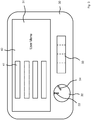
- FIG. 2 and 3 a schematic representation of a panel 30 of the user control terminal 7 is shown.
- the user control terminal 7 is having a display field 31 provided on the display 12 and a control knob 32. Further, input elements 33 are provided on the panel 30 of the user control terminal 7 which, for example, may be provided by a plurality of push buttons.
- the control knob 32 is to be operated in a first and a second knob mode of operation, shown in Fig. 2 and 3 , respectively.
- a first and a second function control user input are received in the user control terminal 30 through the control knob 32, wherein the control knob 32 is in different rotational positions 34, 35 depicted in Fig. 2 .
- first and second function control signals are generated for the functional element 10b of the implement 2, and the functional element 10b is operated according to the first function control signals and, after receiving the second function control user input through the control knob 32, according to the second function control signals.
- a rotation speed of the functional element 10b is changed in response to receiving the second function control user input, wherein the rotation speed may be lowered or increased.
- the control knob 32 in the first knob mode of operation may implement direct steering of a steering element of the implement 2, such as the functional element 10b.
- the steering element is controlled by rotating the control knob 32 of the user control terminal 7 on the tractor 1.
- a present steering position may be indicated by a graphical representation 36 on the display field 31.
- the operation of the control knob 32 may switch to a second knob mode of operation shown in Fig. 3 .
- Such request user input may be received through the control knob 32 and / or, for example, the further input elements 33.
- the user control terminal 7 is prevented from receiving function control user input for the functional element(s) 10b of the implement 2 through the control knob 32. Therefore, direct or real-time control of the functional element(s) 10b through the control knob 32 is not allowed (blocked) in the second knob mode of operation.
- the user control terminal 7 may be prevented from receiving function control user input for the functional element(s) 10a of the tractor 1 through the control knob 32 in the second knob mode of operation.
- the control knob 32 provides for different functionality, namely handling or guiding through a user menu 40 (see Fig. 3 ) displayed on the display field 31 of the display 12 of the user control terminal 7.
- Menu control user input may be received through the control knob 32 for controlling selection of a menu item 41 of the user menu 40 displayed.
- the control knob 32 allows the user to handle or manipulate the user menu displayed.
- FIG. 4 and 5 alternative embodiments are depicted in which the control knob 32 is implemented or provided by a graphical knob element 50 on the display field 31 of the user control terminal 7.
- the operation described above with regard to the rotatable wheel may apply to the graphical knob element 50 mutatis mutandis.
- the graphical knob element 50 may be rotated into the different rotational positions 34, 35 by the user for providing function control user input in the first knob mode of operation as described above.
- Changing of the graphical knob element 50 for example by rotating the graphical knob element 50 on the display field 31 may be caused the user by touching the display field 31 which may be provided as a touch sensitive display.
- the further input elements 33 may allow for user input for changing the graphical knob element 50 for function control user input.
- the user may engage with the graphical knob element 50 for providing menu control user input in the second knob mode of operation applied to the control knob 32 represented by the graphical knob element 50.
Landscapes
- Engineering & Computer Science (AREA)
- Theoretical Computer Science (AREA)
- General Engineering & Computer Science (AREA)
- Life Sciences & Earth Sciences (AREA)
- General Physics & Mathematics (AREA)
- Physics & Mathematics (AREA)
- Human Computer Interaction (AREA)
- Environmental Sciences (AREA)
- Mechanical Engineering (AREA)
- Soil Sciences (AREA)
- Chemical & Material Sciences (AREA)
- Combustion & Propulsion (AREA)
- Transportation (AREA)
- Lifting Devices For Agricultural Implements (AREA)
- Mechanical Control Devices (AREA)
Description
- The present disclosure refers to a method for controlling operation of a user control terminal of an agricultural machine and an agricultural machine.
- For agricultural machines a user control terminal may be provided in a tractor which provides a user interface for receiving user input, for example, for setting limits of operation parameters to be applied for controlling operation of one or more functional elements of an implement trailed by or carried on the tractor. For example, the so called IsoMatch Tellus is provided as a user interface. The user is provided with a user menu on a display of the user control terminal. The user may provide input by engaging with a touch sensitive screen of the user control terminal. In addition or as an alternative, a joystick or a control knob may be provided for selecting menu items displayed on the display of the user control terminal.
-
Document EP 1 380 202 A1 discloses an automatic control system for a harvester. A shutter may be provided which can be switched between different positions, the positions assigned to different operation control with regard to the harvester. - It is an object of the present disclosure to provide a method for controlling operation of a user control terminal of an agricultural machine and an agricultural machine for improving operability of the agricultural machine.
- A method for controlling operation of a user control terminal of an agricultural machine and an agricultural machine according to the
independent claims 1 and 15, respectively, are provided. Alternative embodiments are disclosed in dependent claims. - According to an aspect, a method for controlling operation of a user control terminal of an agricultural machine is provided. The method comprises providing an agricultural machine having a tractor and an implement trailed by or carried on the tractor and a user controlled terminal on the tractor, the user controlled terminal configured for receiving user input through a control knob. The control knob is operated in a first knob mode of operation, comprising: receiving a first function control user input through the control knob; in response to the receiving, generating first function control signals for a functional element of the implement in a control unit functionally connected to the functional element; and operating the functional element according to the first function control signals; receiving a second function control user input through the control knob; in response to the receiving, generating second function control signals for the functional element of the implement in the control unit; and changing operation of the functional element for operating the functional element according to the second function control signals. A request user input for changing knob mode of operation for the control knob is received. In response to the receiving, the control knob is operated in a second knob mode operation, the user controlled terminal being prevented from receiving function control user input through the control knob in the second knob mode operation. The operating of the control knob in the second knob mode of operation comprises: displaying a user menu on a display of the user control terminal; receiving a menu control user input through the control knob; and controlling selection of a menu item in the user menu displayed according to the menu control user input.
- According to another aspect, an agricultural machine is provided, comprising a tractor, an implement trailed by or carried on the tractor, a user controlled terminal on the tractor and a control knob provided on the user control terminal for receiving user input through the control knob. The user control terminal having the control knob is configured to operate the control knob in a first knob mode of operation, comprising: receiving a first function control user input through the control knob; in response to the receiving, generating first function control signals for a functional element of the implement in a control unit functionally connected to the functional element; operating the functional element according to the first function control signals; receiving a second function control user input through the control knob; in response to the receiving, generating second function control signals for the functional element of the implement in the control unit; and changing operation of the functional element for operating the functional element according to the second function control signals. Further, the user controlled terminal is configured a request user input for changing knob mode of operation for the control knob and, in response to the receiving, operate the control knob in a second knob mode of operation, the user controlled terminal being prevented from receiving function control user input through the control knob in the second knob mode of operation. Operating the control knob in the second knob mode operation comprises: displaying a user menu on a display of the user control terminal; receiving a menu control user input through the control knob; and controlling selection of a menu item in the user menu displayed according to the menu control user input.
- The technologies provided allow for switching the control knob function between direct and instant operation control of the functional element of the implement and menu item selection not instantly changing operation of the functional element. In an alternative embodiment, in the second knob mode of operation, operation parameter settings may be received through the control knob, such settings being applied to the functional element at a later stage, therefore not providing for direct or real-time control.
- The technologies disclosed may provide for implementing, by the control knob in the first knob mode of operation, a control element for the operation of the functional element of the implement. By engaging with the control knob in the first knob mode of operation the user may be allowed to instantly and actually control the functional operation state of the functional element of the implement. In direct response to the user engaging with the control knob, the functional element is operated according to present (changing) control signals generated instantly or in real-time in response to the different function control user inputs.
- A changing operation may comprise changing an operation position of the functional element from the first operation position in the first knob mode operation to a second operation position in the second knob mode of operation. For example, the first and second operation position may be a lifted and a lowered operation position. As an alternative or in addition, the first and second operation positions may refer to a proximal or distal position of the functional element with regard to another element of the implement, for example, a support frame.
- The changing of the operation may comprise changing an operation position of the functional element from a first operation position in the first knob mode of operation to a second operation position in the second knob mode of operation.
- The changing of the operation position may comprise changing the operation position of the functional element from a first rotational position in the first mode of operation to a second rotational position in the second mode of operation. For example, a conveyer or a cutting element of a mower may be moved in response to the user input through the control knob in the first knob mode of operation from a first to a second rotational position.
- The changing of the operation position may comprise changing a steering position of a functional steering element from a first steering position in the first knob mode of operation to a second steering position in the second knob mode of operation. Thereby, the user is provided with the option for steering the functional steering element of the implement by engaging with the control knob. Rotating the control knob will turn the functional steering element into different steering positions. In this embodiment, the control knob may implement a steering wheel rotation of which applies rotation of the functional steering element in real-time or an instant manner.
- The changing of the operation may comprise changing an operation position of the functional implement from a first operation speed in the first knob mode operation to a second operation speed in the second knob mode of operation. By rotating the control knob the speed of a rotational movement of the functional element is changed, for example, a speed of rotation (rotational speed). For example, the speed of rotation of the functional element in operation may be increased or lowered in response to the user engaging with the control knob, thereby, rotating the control knob, in the first knob mode of operation. In an alternative, the speed of rotation of a rake element of a rake machine may be changed by rotating the control knob, thereby, receiving functional control user input through the control knob on the user control terminal in the tractor.
- With regard to the method, the providing of the user control terminal may comprise the control knob with a wheel rotatable received on the user control terminal, and the receiving of the user input may comprise determining different rotational positions of the wheel for receiving the first and second control user input.
- With regard to the method, the providing of the user control terminal may comprise providing the control knob with a graphical knob element on the display of the user control terminal, and the receiving of the user input comprises detecting display user input for receiving the first and second function control user input, the display user input engaging with the graphical knob element. Changing the graphical element may refer to rotating the graphical element displayed on the display of the user control terminal in response to the user input. The user input, for example, may be received by the user touching a touch sensitive display or engaging with a joystick and / or a mouse input for rotating the graphical knob element on the display.
- The generating may comprise the first function control signals for the functional element indicating a first value of an operation parameter and the second function control signals for the functional element indicating a second value of an operation parameter, wherein a value difference between the first and second value of the operation parameter is proportional to a position difference between a first rotational position and a second rotational position of the control knob assigned to the first and the second function control user input, respectively. The operation parameter, for example, may refer to speed, height and / or distance. The position difference between the first and the second rotational position may be a difference in the degree of rotation.
- The generating may comprise generating at least one of the first and second function control signals in a central in a control unit connected to the user control terminal, and transmitting at least one of the first and second function control signals from the central control unit to a local control unit on the implement through a data bus, the local control unit connected to the functional and configured to control operation of the functional element.
- The preventing may comprise preventing the user control terminal comprises at least one of preventing generation of the first and second function control signals in the control unit, and preventing transmission of the first and second function control signals from the central control unit to the local control unit. The preventing may comprise interrupting the data bus connection to the local control unit assigned to the functional element. The preventing may comprise setting an operation flag in an operating system in the user control terminal, the operation flag indicating the second mode of operation not allowing or preventing receiving function control user input through the control knob.
- The operating of the functional implement may comprise, in response to the receiving the first and second function control user input, real-time operating the functional element according to the first and second function control signals. A real-time switching may apply for switching of the operation of the functional element from the first to the second functional control signals.
- The operating of the functional element may comprise operating a functional implement element from the following group: rake element, conveyor element, pick-up element, cutting element, wrapping element, lifting element, steering element, spraying element, seeding element, and chamber element of a baler. The functional element may be provided on an implement selected from the following group: mower, baler, sprayer, rake, seeder, and loader wagon.
- The method, in at least one of the first knob mode of operation and the second knob mode of operation, may comprise limiting a rotation of the control knob to a predefined degree of rotation. For example, in the first mode of operation, the limiting of the control knob rotation will limit operation of the functional element. For example, an extent of a relocation of the functional element, e.g. a distance of relocation, may be limited. Thereby, damage to the functional element may be prevented. Such damage may be caused if the functional element, in response to the user input through the control knob, would be moved to a position outside operation limits of the functional element. The operation limits of the functional element may be assigned to the limits of predefined degree of rotation. For example, a maximum distance of movement of the functional element may be assigned to the predefined degree of rotation. The limiting of the rotation of the control knob may be applied to the graphical knob element, for example, by providing proper software control. With regard to the "hardware" control knob, for example, the rotatable wheel, some mechanical and / or electro-mechanic rotation control may be provided which is limiting the rotation of the wheel to the predefined degree of rotation which may be adjustable by the user.
- With regard to the agricultural machine, the alternative embodiments disclosed regarding the method for controlling operation of the user controlled terminal above may apply mutatis mutandis.
- Following, further embodiments are described with reference to the figures. In the figures, show
- Fig. 1
- a schematic representation of a control system of an agricultural machine or system provided with a tractor and an implement trailed by or carried on the tractor;
- Fig. 2
- a schematic representation of a user control terminal having a panel of a control knob provided with a wheel rotatable received on the user control terminal;
- Fig. 3
- a schematic representation of the panel from
Fig. 2 , the control knob being operated in a second knob mode of operation; - Fig. 4
- a schematic representation of a panel of a user controlled terminal having a control knob provided with a graphical knob element on a display of the user control terminal, the control knob being operated in a first knob mode of operation; and
- Fig. 5
- a schematic representation of the panel from
Fig. 4 , the control knob being operated in a second knob mode of operation. -
Fig. 1 shows a schematic representation of an agricultural machine or system having atractor 1 and an implement 2 trailed by or carried on thetractor 1. - An agricultural
machine control network 3 provides for an electronic control system of the agricultural machine or system. The agriculturalmachine control network 3 comprises atractor control network 4 and an implementcontrol network 5. The agriculturalmachine control network 3 is having adata bus 6 to which, according to the embodiment shown, auser control terminal 7, atask controller 8, and a plurality ofelectronic control units 9 are connected. Each of theelectronic control units 9 is assigned to afunctional element tractor 1 and the implement 2, respectively. In an alternative embodiment, theelectronic control units 9 connected to theuser control terminal 7 through the data bus may only be applied to the functional element(s) 10b of the implement 2, but not to the functional element(s) 10a of the tractor. - With regard to the implement 2, the
functional elements 10b may also be to as working or functional unit. Through thedata bus 6 electronic data may be transmitted between the components, units, modules or elements connected to thedata bus 6. The electronic control system of the agriculturalmachine control network 3 may implement the ISO 11783 standard, preferably the ISO 11783-11 standard. - The
data bus 6 is provided with aplug connector 11 connecting thetractor control network 4 and the implementcontrol network 5. - The user or
operator control terminal 7 is provided with aterminal display 12 and provides for user control and user display. Further, theuser control terminal 7 is provided with a processor unit comprising a processor and a memory element connected to the processor. Multiple software applications implemented on the user terminal may be running simultaneously. - Through the
user control terminal 7 user input may be received for controlling thefunctional elements terminal display 12 operation information may be displayed to the user. - Referring to
Fig. 2 and3 , a schematic representation of apanel 30 of theuser control terminal 7 is shown. Theuser control terminal 7 is having adisplay field 31 provided on thedisplay 12 and acontrol knob 32. Further,input elements 33 are provided on thepanel 30 of theuser control terminal 7 which, for example, may be provided by a plurality of push buttons. - The
control knob 32 is to be operated in a first and a second knob mode of operation, shown inFig. 2 and3 , respectively. In the first knob mode of operation, according toFig. 2 , a first and a second function control user input are received in theuser control terminal 30 through thecontrol knob 32, wherein thecontrol knob 32 is in differentrotational positions Fig. 2 . In response to the receiving of the first and second function control user input, first and second function control signals are generated for thefunctional element 10b of the implement 2, and thefunctional element 10b is operated according to the first function control signals and, after receiving the second function control user input through thecontrol knob 32, according to the second function control signals. For example, a rotation speed of thefunctional element 10b is changed in response to receiving the second function control user input, wherein the rotation speed may be lowered or increased. In an alternative embodiment, thecontrol knob 32 in the first knob mode of operation may implement direct steering of a steering element of the implement 2, such as thefunctional element 10b. The steering element is controlled by rotating thecontrol knob 32 of theuser control terminal 7 on thetractor 1. According toFig. 2 , a present steering position may be indicated by agraphical representation 36 on thedisplay field 31. - In response to a request user input for changing knob mode of operation for the
control knob 32, the operation of thecontrol knob 32 may switch to a second knob mode of operation shown inFig. 3 . Such request user input may be received through thecontrol knob 32 and / or, for example, thefurther input elements 33. In the second knob mode of operation, theuser control terminal 7 is prevented from receiving function control user input for the functional element(s) 10b of the implement 2 through thecontrol knob 32. Therefore, direct or real-time control of the functional element(s) 10b through thecontrol knob 32 is not allowed (blocked) in the second knob mode of operation. In a similar way, if theuser control terminal 7 is connected to thefunctional elements 10a of thetractor 1, theuser control terminal 7 may be prevented from receiving function control user input for the functional element(s) 10a of thetractor 1 through thecontrol knob 32 in the second knob mode of operation. - In the second knob mode of operation, the
control knob 32 provides for different functionality, namely handling or guiding through a user menu 40 (seeFig. 3 ) displayed on thedisplay field 31 of thedisplay 12 of theuser control terminal 7. Menu control user input may be received through thecontrol knob 32 for controlling selection of amenu item 41 of theuser menu 40 displayed. In the second knob mode of operation, thecontrol knob 32 allows the user to handle or manipulate the user menu displayed. - Referring to
Fig. 4 and5 , alternative embodiments are depicted in which thecontrol knob 32 is implemented or provided by agraphical knob element 50 on thedisplay field 31 of theuser control terminal 7. The operation described above with regard to the rotatable wheel may apply to thegraphical knob element 50 mutatis mutandis. Thegraphical knob element 50 may be rotated into the differentrotational positions graphical knob element 50, for example by rotating thegraphical knob element 50 on thedisplay field 31 may be caused the user by touching thedisplay field 31 which may be provided as a touch sensitive display. As an alternative, thefurther input elements 33 may allow for user input for changing thegraphical knob element 50 for function control user input. Similarly, according toFig. 5 the user may engage with thegraphical knob element 50 for providing menu control user input in the second knob mode of operation applied to thecontrol knob 32 represented by thegraphical knob element 50.
Claims (15)
- A method for controlling operation of a user control terminal of an agricultural machine, comprising- providing an agricultural machine having a tractor (1) and an implement (2) trailed by or carried on the tractor (1);- providing a user control terminal (7) on the tractor (1), the user control terminal (7) configured for receiving user input through a control knob (32);- operating the control knob (32) in a first knob mode of operation, comprising- receiving a first function control user input through the control knob (32);- in response to the receiving, generating first function control signals for a functional element (10a; 10b) of the implement (2) in a control unit (9) functionally connected to the functional element (10a; 10b);- operating the functional element (10a; 10b) according to the first function control signals;- receiving a second function control user input through the control knob (32);- in response to the receiving, generating second function control signals for the functional element (10a; 10b) of the implement (2) in the control unit (9); and- changing operation of the functional element (10a; 10b) for operating the functional element (10a; 10b) according to the second function control signals;characterized by- receiving a request user input for changing knob mode of operation for the control knob (32); and- in response to the receiving, operating the control knob (32) in a second knob mode of operation, the user control terminal (7) prevented from receiving function control user input through the control knob (32) in the second knob mode of operation, comprising- displaying a user menu (40) on a display (12) of the user control terminal (7);- receiving a menu control user input through the control knob (32); and- controlling selection of a menu item in the user menu (40) displayed according to the menu control user input.
- The method according to claim 1, wherein the changing operation comprises changing an operation position of the functional element (10a; 10b) from a first operation position in the first knob mode of operation to a second operation position in the second knob mode of operation.
- The method according to claim 2, wherein the changing the operation position comprises changing the operation position of the functional element (10a; 10b) from a first rotational position in the first mode of operation to a second rotational position in the second mode of operation.
- The method according to at least one of the preceding claims, wherein the changing the operation position comprises changing a steering position of a functional steering element from a first steering position in the first knob mode of operation to a second steering position in the second knob mode of operation.
- The method according to at least one of the preceding claims, wherein the changing operation comprises changing an operation position of the functional implement (10a; 10b) from a first operation speed in the first knob mode operation to a second operation speed in the second knob mode of operation.
- The method according to at least one of the preceding claims, wherein- the providing of the user control terminal (7) comprises providing the control knob (32) with a wheel rotatable received on the user control terminal (7); and- the receiving of the user input comprises determining different rotational positions of the wheel for receiving the first and second function control user input.
- The method according to at least one of the preceding claims, wherein- the providing of the user control terminal (7) comprises providing the control knob (32) with a graphical knob element on the display (12) of the user control terminal (7); and- the receiving of the user input comprises detecting display user input for receiving the first and second function control user input, the display user input engaging with the graphical knob element.
- The method according to at least one of the preceding claims, wherein the generating comprises- the first function control signals for the functional element (10a; 10b) indicating a first value of an operation parameter; and- the second function control signals for the functional element (10a; 10b) indicating a second value of an operation parameter;wherein a value difference between the first and second value of the operation parameter is proportional to a position difference between a first rotational position and a second rotational position of the control knob (32) assigned to the first and the second function control user input, respectively.
- The method according to at least one of the preceding claims, wherein the generating comprises- generating at least one of the first and second function control signals in a central control unit connected to the user control terminal (7); and- transmitting at least one of the first and second function control signals from the central control unit to a local control unit on the implement (2) through a data bus, the local control unit connected to the functional and configured to control operation of the functional element (10a; 10b).
- The method according to at least one of the preceding claims, wherein the preventing the user control terminal (7) comprises at least one of- preventing generation of the first and second function control signals in the control unit; and- preventing transmission of the first and second function control signals from the central control unit to the local control unit.
- The method according to at least one of the preceding claims, wherein the operating of the functional implement (10a; 10b) comprises, in response to the receiving the first and second function control user input, real-time operating the functional element (10a; 10b) according to the first and second function control signals.
- The method according to at least one of the preceding claims, wherein the operating of the functional element (10a; 10b) comprises operating a functional implement element from the following group: rake element, conveyor element, pick-up element, cutting element, wrapping element, lifting element, steering element, spraying element, seeding element, and chamber element of a baler.
- The method according to at least one of the preceding claims, wherein the providing the user control terminal (7) comprises providing a central user control terminal on the tractor (1), the central user control terminal configured for receiving user input for setting implement modes of operation for the implement (2), and tractor modes of operation for the tractor (1).
- The method according to at least one of the preceding claims, further comprising, in at least one of the first knob mode of operation and the second knob mode of operation, limiting a rotation of the control knob (32) to a predefined degree of rotation.
- An agricultural machine, comprising- a tractor (1);- an implement (2) trailed by or carried on the tractor (1);- a user control terminal (7) on the tractor (1); and- a control knob (32) provided on the user control terminal (7) for receiving user input through the control knob (32);wherein the user control terminal (7) having the control knob (32) is configured to- operate the control knob (32) in a first knob mode of operation, comprising- receiving a first function control user input through the control knob (32);- in response to the receiving, generating first function control signals for a functional element (10a; 10b) of the implement (2) in a control unit functionally connected to the functional element (10a; 10b);- operating the functional element (10a; 10b) according to the first function control signals;- receiving a second function control user input through the control knob (32);- in response to the receiving, generating second function control signals for the functional element (10a; 10b) of the implement (2) in the control unit (9); and- changing operation of the functional element (10a; 10b) for operating the functional element (10a; 10b) according to the second function control signals;characterized in that the user control terminal (7) is further configured to receive a request user input for changing knob mode of operation for the control knob (32); and- in response to the receiving, operate the control knob (32) in a second knob mode of operation, the user control terminal (7) prevented from receiving function control user input through the control knob (32) in the second knob mode of operation, comprising- displaying a user menu (40) on a display (12) of the user control terminal (7);- receiving a menu control user input through the control knob (32); and- controlling selection of a menu item in the user menu (40) displayed according to the menu control user input.
Priority Applications (2)
| Application Number | Priority Date | Filing Date | Title |
|---|---|---|---|
| EP17172820.7A EP3406120B1 (en) | 2017-05-24 | 2017-05-24 | Method for controlling operation of a user control terminal of an agricultural machine and agricultural machine |
| US15/987,055 US20180338406A1 (en) | 2017-05-24 | 2018-05-23 | Method for controlling operation of a user control terminal of an agricultural machine and agricultural machine |
Applications Claiming Priority (1)
| Application Number | Priority Date | Filing Date | Title |
|---|---|---|---|
| EP17172820.7A EP3406120B1 (en) | 2017-05-24 | 2017-05-24 | Method for controlling operation of a user control terminal of an agricultural machine and agricultural machine |
Publications (2)
| Publication Number | Publication Date |
|---|---|
| EP3406120A1 EP3406120A1 (en) | 2018-11-28 |
| EP3406120B1 true EP3406120B1 (en) | 2019-12-11 |
Family
ID=58994838
Family Applications (1)
| Application Number | Title | Priority Date | Filing Date |
|---|---|---|---|
| EP17172820.7A Active EP3406120B1 (en) | 2017-05-24 | 2017-05-24 | Method for controlling operation of a user control terminal of an agricultural machine and agricultural machine |
Country Status (2)
| Country | Link |
|---|---|
| US (1) | US20180338406A1 (en) |
| EP (1) | EP3406120B1 (en) |
Families Citing this family (1)
| Publication number | Priority date | Publication date | Assignee | Title |
|---|---|---|---|---|
| DE102019117604A1 (en) | 2019-06-28 | 2020-12-31 | elobau GmbH & Co.KG | Adaptive operating device |
Family Cites Families (4)
| Publication number | Priority date | Publication date | Assignee | Title |
|---|---|---|---|---|
| US6681551B1 (en) * | 2002-07-11 | 2004-01-27 | Deere & Co. | Programmable function control for combine |
| US7686095B2 (en) * | 2004-10-28 | 2010-03-30 | Cnh America Llc | Implement height control system |
| GB0507928D0 (en) * | 2005-04-20 | 2005-05-25 | Cnh Belgium Nv | Input device for agricultural vehicle information display |
| US10289217B2 (en) * | 2016-07-13 | 2019-05-14 | Toyota Motor Engineering & Manufacturing North America, Inc. | Multi-function control knobs for multimedia systems of vehicles |
-
2017
- 2017-05-24 EP EP17172820.7A patent/EP3406120B1/en active Active
-
2018
- 2018-05-23 US US15/987,055 patent/US20180338406A1/en not_active Abandoned
Non-Patent Citations (1)
| Title |
|---|
| None * |
Also Published As
| Publication number | Publication date |
|---|---|
| EP3406120A1 (en) | 2018-11-28 |
| US20180338406A1 (en) | 2018-11-29 |
Similar Documents
| Publication | Publication Date | Title |
|---|---|---|
| EP2798939B1 (en) | Operating system for and method of operating a controllable transfer device for harvested goods | |
| EP4062740B1 (en) | Control system for controlling filling mechanisms in communication with a mobile device | |
| US8473654B2 (en) | Computer input switching device | |
| JP5740090B2 (en) | Agricultural machine remote control system | |
| CA2820467C (en) | Electronic control and display unit | |
| EP4056019B1 (en) | Agricultural harvester with operator commanded placement for control of discharge spout | |
| EP1714539B1 (en) | Settings control of an agricultural vehicle | |
| EP1714823B1 (en) | Input device for agricultural vehicle information display | |
| CA2996343C (en) | Harvesting machine with programmable inputs for header height and auxiliary function control | |
| US20180329618A1 (en) | Agricultural machine | |
| US20140053093A1 (en) | Electronic control and display unit | |
| US20080255712A1 (en) | System for customizing responsiveness of a machine | |
| US20200296892A1 (en) | Forward-looking perception interface and control | |
| CN109725713B (en) | Augmented reality control for a machine | |
| EP3406120A1 (en) | Method for controlling operation of a user control terminal of an agricultural machine and agricultural machine | |
| US11269307B2 (en) | Method for operating an agricultural implement and arrangement comprising an agricultural implement | |
| CN114096146A (en) | Method for observing working process of agricultural machine, digital video system and agricultural machine | |
| CN115645924B (en) | Virtual item processing method, device and electronic terminal | |
| EP1714847B1 (en) | Agricultural vehicle with reconfigurable control | |
| EP3420789A1 (en) | Method for operating an agricultural system and agricultural system | |
| US20260072466A1 (en) | Input device with upper and lower wheel for controlling an agricultural machine | |
| EP3243375B1 (en) | Method of operating an agricultural system for forming and / or wrapping a bale of crop and agricultural system | |
| US20190152321A1 (en) | Control system for an agricultural working vehicle | |
| EP4305941A1 (en) | Improved work vehicle and control method thereof | |
| EP4197843B1 (en) | Vehicle console with a screen to display overlapping graphical user interfaces and method for safe interaction with overlapping graphical user interfaces |
Legal Events
| Date | Code | Title | Description |
|---|---|---|---|
| PUAI | Public reference made under article 153(3) epc to a published international application that has entered the european phase |
Free format text: ORIGINAL CODE: 0009012 |
|
| STAA | Information on the status of an ep patent application or granted ep patent |
Free format text: STATUS: REQUEST FOR EXAMINATION WAS MADE |
|
| 17P | Request for examination filed |
Effective date: 20180404 |
|
| AK | Designated contracting states |
Kind code of ref document: A1 Designated state(s): AL AT BE BG CH CY CZ DE DK EE ES FI FR GB GR HR HU IE IS IT LI LT LU LV MC MK MT NL NO PL PT RO RS SE SI SK SM TR |
|
| AX | Request for extension of the european patent |
Extension state: BA ME |
|
| GRAP | Despatch of communication of intention to grant a patent |
Free format text: ORIGINAL CODE: EPIDOSNIGR1 |
|
| STAA | Information on the status of an ep patent application or granted ep patent |
Free format text: STATUS: GRANT OF PATENT IS INTENDED |
|
| INTG | Intention to grant announced |
Effective date: 20190703 |
|
| GRAS | Grant fee paid |
Free format text: ORIGINAL CODE: EPIDOSNIGR3 |
|
| GRAA | (expected) grant |
Free format text: ORIGINAL CODE: 0009210 |
|
| STAA | Information on the status of an ep patent application or granted ep patent |
Free format text: STATUS: THE PATENT HAS BEEN GRANTED |
|
| AK | Designated contracting states |
Kind code of ref document: B1 Designated state(s): AL AT BE BG CH CY CZ DE DK EE ES FI FR GB GR HR HU IE IS IT LI LT LU LV MC MK MT NL NO PL PT RO RS SE SI SK SM TR |
|
| REG | Reference to a national code |
Ref country code: GB Ref legal event code: FG4D |
|
| REG | Reference to a national code |
Ref country code: CH Ref legal event code: EP |
|
| REG | Reference to a national code |
Ref country code: AT Ref legal event code: REF Ref document number: 1211218 Country of ref document: AT Kind code of ref document: T Effective date: 20191215 |
|
| REG | Reference to a national code |
Ref country code: DE Ref legal event code: R096 Ref document number: 602017009517 Country of ref document: DE |
|
| REG | Reference to a national code |
Ref country code: IE Ref legal event code: FG4D |
|
| REG | Reference to a national code |
Ref country code: NL Ref legal event code: FP |
|
| REG | Reference to a national code |
Ref country code: LT Ref legal event code: MG4D |
|
| PG25 | Lapsed in a contracting state [announced via postgrant information from national office to epo] |
Ref country code: FI Free format text: LAPSE BECAUSE OF FAILURE TO SUBMIT A TRANSLATION OF THE DESCRIPTION OR TO PAY THE FEE WITHIN THE PRESCRIBED TIME-LIMIT Effective date: 20191211 Ref country code: BG Free format text: LAPSE BECAUSE OF FAILURE TO SUBMIT A TRANSLATION OF THE DESCRIPTION OR TO PAY THE FEE WITHIN THE PRESCRIBED TIME-LIMIT Effective date: 20200311 Ref country code: LV Free format text: LAPSE BECAUSE OF FAILURE TO SUBMIT A TRANSLATION OF THE DESCRIPTION OR TO PAY THE FEE WITHIN THE PRESCRIBED TIME-LIMIT Effective date: 20191211 Ref country code: SE Free format text: LAPSE BECAUSE OF FAILURE TO SUBMIT A TRANSLATION OF THE DESCRIPTION OR TO PAY THE FEE WITHIN THE PRESCRIBED TIME-LIMIT Effective date: 20191211 Ref country code: NO Free format text: LAPSE BECAUSE OF FAILURE TO SUBMIT A TRANSLATION OF THE DESCRIPTION OR TO PAY THE FEE WITHIN THE PRESCRIBED TIME-LIMIT Effective date: 20200311 Ref country code: GR Free format text: LAPSE BECAUSE OF FAILURE TO SUBMIT A TRANSLATION OF THE DESCRIPTION OR TO PAY THE FEE WITHIN THE PRESCRIBED TIME-LIMIT Effective date: 20200312 Ref country code: LT Free format text: LAPSE BECAUSE OF FAILURE TO SUBMIT A TRANSLATION OF THE DESCRIPTION OR TO PAY THE FEE WITHIN THE PRESCRIBED TIME-LIMIT Effective date: 20191211 |
|
| PG25 | Lapsed in a contracting state [announced via postgrant information from national office to epo] |
Ref country code: HR Free format text: LAPSE BECAUSE OF FAILURE TO SUBMIT A TRANSLATION OF THE DESCRIPTION OR TO PAY THE FEE WITHIN THE PRESCRIBED TIME-LIMIT Effective date: 20191211 Ref country code: RS Free format text: LAPSE BECAUSE OF FAILURE TO SUBMIT A TRANSLATION OF THE DESCRIPTION OR TO PAY THE FEE WITHIN THE PRESCRIBED TIME-LIMIT Effective date: 20191211 |
|
| PG25 | Lapsed in a contracting state [announced via postgrant information from national office to epo] |
Ref country code: AL Free format text: LAPSE BECAUSE OF FAILURE TO SUBMIT A TRANSLATION OF THE DESCRIPTION OR TO PAY THE FEE WITHIN THE PRESCRIBED TIME-LIMIT Effective date: 20191211 |
|
| PG25 | Lapsed in a contracting state [announced via postgrant information from national office to epo] |
Ref country code: EE Free format text: LAPSE BECAUSE OF FAILURE TO SUBMIT A TRANSLATION OF THE DESCRIPTION OR TO PAY THE FEE WITHIN THE PRESCRIBED TIME-LIMIT Effective date: 20191211 Ref country code: ES Free format text: LAPSE BECAUSE OF FAILURE TO SUBMIT A TRANSLATION OF THE DESCRIPTION OR TO PAY THE FEE WITHIN THE PRESCRIBED TIME-LIMIT Effective date: 20191211 Ref country code: RO Free format text: LAPSE BECAUSE OF FAILURE TO SUBMIT A TRANSLATION OF THE DESCRIPTION OR TO PAY THE FEE WITHIN THE PRESCRIBED TIME-LIMIT Effective date: 20191211 Ref country code: CZ Free format text: LAPSE BECAUSE OF FAILURE TO SUBMIT A TRANSLATION OF THE DESCRIPTION OR TO PAY THE FEE WITHIN THE PRESCRIBED TIME-LIMIT Effective date: 20191211 Ref country code: PT Free format text: LAPSE BECAUSE OF FAILURE TO SUBMIT A TRANSLATION OF THE DESCRIPTION OR TO PAY THE FEE WITHIN THE PRESCRIBED TIME-LIMIT Effective date: 20200506 |
|
| PG25 | Lapsed in a contracting state [announced via postgrant information from national office to epo] |
Ref country code: SM Free format text: LAPSE BECAUSE OF FAILURE TO SUBMIT A TRANSLATION OF THE DESCRIPTION OR TO PAY THE FEE WITHIN THE PRESCRIBED TIME-LIMIT Effective date: 20191211 Ref country code: IS Free format text: LAPSE BECAUSE OF FAILURE TO SUBMIT A TRANSLATION OF THE DESCRIPTION OR TO PAY THE FEE WITHIN THE PRESCRIBED TIME-LIMIT Effective date: 20200411 Ref country code: SK Free format text: LAPSE BECAUSE OF FAILURE TO SUBMIT A TRANSLATION OF THE DESCRIPTION OR TO PAY THE FEE WITHIN THE PRESCRIBED TIME-LIMIT Effective date: 20191211 |
|
| REG | Reference to a national code |
Ref country code: DE Ref legal event code: R097 Ref document number: 602017009517 Country of ref document: DE |
|
| PLBE | No opposition filed within time limit |
Free format text: ORIGINAL CODE: 0009261 |
|
| STAA | Information on the status of an ep patent application or granted ep patent |
Free format text: STATUS: NO OPPOSITION FILED WITHIN TIME LIMIT |
|
| PG25 | Lapsed in a contracting state [announced via postgrant information from national office to epo] |
Ref country code: DK Free format text: LAPSE BECAUSE OF FAILURE TO SUBMIT A TRANSLATION OF THE DESCRIPTION OR TO PAY THE FEE WITHIN THE PRESCRIBED TIME-LIMIT Effective date: 20191211 |
|
| 26N | No opposition filed |
Effective date: 20200914 |
|
| PG25 | Lapsed in a contracting state [announced via postgrant information from national office to epo] |
Ref country code: SI Free format text: LAPSE BECAUSE OF FAILURE TO SUBMIT A TRANSLATION OF THE DESCRIPTION OR TO PAY THE FEE WITHIN THE PRESCRIBED TIME-LIMIT Effective date: 20191211 |
|
| PG25 | Lapsed in a contracting state [announced via postgrant information from national office to epo] |
Ref country code: LI Free format text: LAPSE BECAUSE OF NON-PAYMENT OF DUE FEES Effective date: 20200531 Ref country code: CH Free format text: LAPSE BECAUSE OF NON-PAYMENT OF DUE FEES Effective date: 20200531 Ref country code: MC Free format text: LAPSE BECAUSE OF FAILURE TO SUBMIT A TRANSLATION OF THE DESCRIPTION OR TO PAY THE FEE WITHIN THE PRESCRIBED TIME-LIMIT Effective date: 20191211 |
|
| PG25 | Lapsed in a contracting state [announced via postgrant information from national office to epo] |
Ref country code: PL Free format text: LAPSE BECAUSE OF FAILURE TO SUBMIT A TRANSLATION OF THE DESCRIPTION OR TO PAY THE FEE WITHIN THE PRESCRIBED TIME-LIMIT Effective date: 20191211 |
|
| PG25 | Lapsed in a contracting state [announced via postgrant information from national office to epo] |
Ref country code: LU Free format text: LAPSE BECAUSE OF NON-PAYMENT OF DUE FEES Effective date: 20200524 |
|
| PG25 | Lapsed in a contracting state [announced via postgrant information from national office to epo] |
Ref country code: IE Free format text: LAPSE BECAUSE OF NON-PAYMENT OF DUE FEES Effective date: 20200524 |
|
| REG | Reference to a national code |
Ref country code: AT Ref legal event code: UEP Ref document number: 1211218 Country of ref document: AT Kind code of ref document: T Effective date: 20191211 |
|
| PG25 | Lapsed in a contracting state [announced via postgrant information from national office to epo] |
Ref country code: TR Free format text: LAPSE BECAUSE OF FAILURE TO SUBMIT A TRANSLATION OF THE DESCRIPTION OR TO PAY THE FEE WITHIN THE PRESCRIBED TIME-LIMIT Effective date: 20191211 Ref country code: MT Free format text: LAPSE BECAUSE OF FAILURE TO SUBMIT A TRANSLATION OF THE DESCRIPTION OR TO PAY THE FEE WITHIN THE PRESCRIBED TIME-LIMIT Effective date: 20191211 Ref country code: CY Free format text: LAPSE BECAUSE OF FAILURE TO SUBMIT A TRANSLATION OF THE DESCRIPTION OR TO PAY THE FEE WITHIN THE PRESCRIBED TIME-LIMIT Effective date: 20191211 |
|
| PG25 | Lapsed in a contracting state [announced via postgrant information from national office to epo] |
Ref country code: MK Free format text: LAPSE BECAUSE OF FAILURE TO SUBMIT A TRANSLATION OF THE DESCRIPTION OR TO PAY THE FEE WITHIN THE PRESCRIBED TIME-LIMIT Effective date: 20191211 |
|
| P01 | Opt-out of the competence of the unified patent court (upc) registered |
Effective date: 20230525 |
|
| PGFP | Annual fee paid to national office [announced via postgrant information from national office to epo] |
Ref country code: NL Payment date: 20250521 Year of fee payment: 9 |
|
| PGFP | Annual fee paid to national office [announced via postgrant information from national office to epo] |
Ref country code: DE Payment date: 20250521 Year of fee payment: 9 |
|
| PGFP | Annual fee paid to national office [announced via postgrant information from national office to epo] |
Ref country code: GB Payment date: 20250527 Year of fee payment: 9 |
|
| PGFP | Annual fee paid to national office [announced via postgrant information from national office to epo] |
Ref country code: IT Payment date: 20250527 Year of fee payment: 9 Ref country code: BE Payment date: 20250521 Year of fee payment: 9 |
|
| PGFP | Annual fee paid to national office [announced via postgrant information from national office to epo] |
Ref country code: FR Payment date: 20250528 Year of fee payment: 9 |
|
| PGFP | Annual fee paid to national office [announced via postgrant information from national office to epo] |
Ref country code: AT Payment date: 20250522 Year of fee payment: 9 |