EP3405758B1 - Flexible nuclear level sensing gauge - Google Patents
Flexible nuclear level sensing gauge Download PDFInfo
- Publication number
- EP3405758B1 EP3405758B1 EP17703559.9A EP17703559A EP3405758B1 EP 3405758 B1 EP3405758 B1 EP 3405758B1 EP 17703559 A EP17703559 A EP 17703559A EP 3405758 B1 EP3405758 B1 EP 3405758B1
- Authority
- EP
- European Patent Office
- Prior art keywords
- light
- scintillating
- gauge
- scintillators
- fibers
- Prior art date
- Legal status (The legal status is an assumption and is not a legal conclusion. Google has not performed a legal analysis and makes no representation as to the accuracy of the status listed.)
- Active
Links
Images




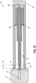


Classifications
-
- G—PHYSICS
- G01—MEASURING; TESTING
- G01F—MEASURING VOLUME, VOLUME FLOW, MASS FLOW OR LIQUID LEVEL; METERING BY VOLUME
- G01F23/00—Indicating or measuring liquid level or level of fluent solid material, e.g. indicating in terms of volume or indicating by means of an alarm
- G01F23/22—Indicating or measuring liquid level or level of fluent solid material, e.g. indicating in terms of volume or indicating by means of an alarm by measuring physical variables, other than linear dimensions, pressure or weight, dependent on the level to be measured, e.g. by difference of heat transfer of steam or water
- G01F23/28—Indicating or measuring liquid level or level of fluent solid material, e.g. indicating in terms of volume or indicating by means of an alarm by measuring physical variables, other than linear dimensions, pressure or weight, dependent on the level to be measured, e.g. by difference of heat transfer of steam or water by measuring the variations of parameters of electromagnetic or acoustic waves applied directly to the liquid or fluent solid material
- G01F23/284—Electromagnetic waves
- G01F23/288—X-rays; Gamma rays or other forms of ionising radiation
-
- G—PHYSICS
- G01—MEASURING; TESTING
- G01T—MEASUREMENT OF NUCLEAR OR X-RADIATION
- G01T1/00—Measuring X-radiation, gamma radiation, corpuscular radiation, or cosmic radiation
- G01T1/16—Measuring radiation intensity
- G01T1/20—Measuring radiation intensity with scintillation detectors
Definitions
- Level sensors are typically attached to the holding tank or bin, and electrically connected to remote gauges at a control room or other central location, where technicians or control systems may monitor the status of the bins to provide the appropriate process control.
- Various technologies have been developed for level sensing. These include various contact sensing technologies using floats or drop weights, as well as various non-contact technologies, such as reflecting electromagnetic radiation or ultrasonic vibrations from the surface of the product in the bin to determine the height of the product. In some applications, it is particularly important to move the sensor away from the product. For example, in a foundry where the level of a hot melt of steel or ore is to be level sensed, it is particularly important to keep the level sensor a safe distance from the hot melt. In these applications, nuclear level sensing gauges are used.
- a source of nuclear radiation is positioned on one side of the bin to be level sensed.
- a nuclear radiation detector is placed on the opposite side of the bin.
- the radiation exiting the source is in the shape of a wide, generally vertically dispersed beam, directed toward the interior of the bin.
- the product in the bin substantially absorbs the radiation that impinges upon it. If, however, the bin is not full of product, some part of the beam of radiation from the source passes through the bin and irradiates the radiation detector on the opposite side of the bin from the radiation source.
- the amount of radiation stimulating the radiation detector is inversely proportional to the amount of product in the bin.
- the radiation reaching the detector creates scintillating light flashes in the detector.
- the number of light flashes is proportional to the intensity of the incident radiation.
- a high sensitivity light sensor converts the light flashes into electrical pulses, which are amplified and evaluated by electronics to produce a measurement of the amount of product in the bin.
- nuclear level sensing gauges have used an elongated scintillating crystal as a radiation detector.
- the scintillating crystal produces photons of light when exposed to nuclear radiation from a radiation source. The number of photons produced is related to the amount of radiation impinging on the crystal.
- a photomultiplier tube (PMT), used as a light sensor, is coupled to an end of the crystal. The PMT detects photons of light emanating from the scintillating crystal, and produces a signal indicative of the amount of radiation impinging on the crystal and, thus, the level of product in the bin.
- This type of sensor is discussed in U.S. Pat. Nos. 3,884,288 , 4,481,595 , 4,651,800 , 4,735,253 , 4,739,819 and 5,564,487 .
- Scintillating fibers can be readily curved to match the curvature of a particular bin, whereas crystals are rigid and difficult to custom manufacture. Also, scintillating fibers have better internal reflection characteristics than crystals, meaning that fiber scintillating detectors can be made longer with less loss than crystal scintillating detectors. Finally, a bundle of one or more fibers can have substantially less heat capacity than the corresponding crystal, meaning the bundle is more readily cooled.
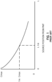
- Fig. 1 illustrates the decay of light intensity as a function of the distance of travel from a scintillation source through a medium, and the definition of the "attenuation length" L (1/e) of a medium, which is defined as the distance that light can be transmitted through a medium before the light intensity is reduced to 1/e of its intensity at its origin.
- a fiber bundle typically has an attenuation length of about 2.5 meters.
- Fiber bundles and crystals have been used commercially at long lengths, up to 10 feet for crystals and 12 feet or longer for fiber bundles. Crystals are practically limited to approximately 10 foot lengths because of the difficulty of manufacturing bars in longer sizes. Fibers are not practically limited by manufacturing constraints, but are constrained by the attenuation length of the polystyrene medium used to make the fibers.
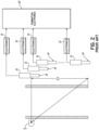
- Fig. 2 shows a typical prior art arrangement of this kind, in which a plurality of scintillating crystals 14 are placed in a serial fashion adjacent a bin opposite to a radiation source S, each crystal stimulating a photomultiplier tube 12 which is coupled to electronic amplifiers 10. The output of the various amplifiers 10 is then coupled to summation electronics 20.
- Each crystal 14 has a length less than the attenuation length of the crystal medium, but the serially positioned crystals have a collective length Lt that can be substantially greater than the attenuation length.
- FIG. 3 shows an alternative, serialized arrangement of crystals 14 that has been used in installations where it is desired to move the photomultiplier tubes 12 remote from the crystals 14.
- a light guide 18 couples light from each crystal 14 to each PMT 12.
- the crystals are generally cut to a length less than the attenuation length of the crystal medium, but have a collective length Lt that can be substantially longer. While the arrangements illustrated in Figs. 2 and 3 facilitate longer length applications, these gauges are highly complex and costly, due to the replication of the PMT 12 and electronics 10, and the requirement for a summation electronics unit 20.
- Applicants in U.S. Patent Application Serial No. 13/798,179 , published as US 2014/0264040 A1 , disclose the use of a nuclear level sensing gauge having a plurality of scintillators, positioned in a serial fashion, adjacent the product in a bin.
- the scintillators are positioned on the opposite side of the bin from the nuclear source.
- the level sensing gauge uses a plurality of light guides 18 to couple light from the scintillators (either crystals 14 or fiber bundles 16) to a common light sensor or PMT 12, so that the common light sensor detects light generated in two or more scintillators. Accordingly, the number of photons generated in the scintillators is measured by a single light sensor, producing a measure of radiation-absorbing product in the bin, without the cost and complexity of multiple PMTs and amplifying electronics, as in the previous gauges.
- Light guides have been cemented or otherwise securely affixed to the scintillators to optically couple the scintillators and light guides.
- tight, durable contact couplings can be difficult to assemble in the field, due to the harsh operating environment of many nuclear gauge applications. Additionally, the contact couplings in the light path may degrade over time due to movement or the harsh environment, adversely affecting operation of the gauge.
- Measurement applications also may dictate a more flexible gauge in order to conform the gauge to the curvature of the bin or vessel being measured. For example, it can be desirable for the gauge to spiral down the exterior of a vessel in order to more accurately measure the contents of the vessel. While gauges have been developed with some degree of flexibility, this flexibility has been limited due to the need to maintain coupling contact between the scintillator and light guide. Prior gauges have attempted to couple the scintillator and light guide through an air gap, but the air gap can fill with water and freeze, causing refraction of the light and loss of output.
- a nuclear level sensing gauge with increased flexibility that can bend in three dimensions in order to conform the gauge to the shape of the product bin or vessel. Additionally, it is desirable to have a nuclear level sensing gauge that does not require coupling contact between the scintillator and light guide in order to transfer light from the scintillating detectors to the light sensor.
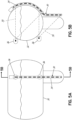
- FIGs. 5A and 5B illustrate a first embodiment for a nuclear level sensing gauge 30, shown attached to a vessel or bin 32, for measuring the level of product in the bin.
- Gauge 30 includes a housing 34 enclosing the scintillating components of the gauge.
- Housing 34 is an elongated tube, which may optionally be formed of a flexible material, which is sufficiently resilient to provide protection for the scintillating components from harsh operating conditions. Housing 34 also prevents ambient light from penetrating into the gauge 30. Examples of suitable materials for housing 34 include corrugated stainless steel tubing with a rubberized outer wall, and braided nylon for abrasion protection.
- Housing 34 is attached to the exterior of bin 32 on the opposite side of the bin from a radiation source 36.
- a radiation source 36 In the measurement application shown, two radiation sources 36 are utilized to accommodate a longer length gauge 30. However, any number of radiation sources may be utilized with the gauge 30, depending upon the vessel size, measurement range, sensitivity profile, and other requirements of the measurement application.
- light from a primary scintillator 40 is coupled to a common light sensor 12 using a light guide 44 which may be composed of one or more scintillating fibers.
- the light guide 44 may comprise a bundle having approximately 50 scintillating fibers.
- the primary scintillator 40 generates scintillating light 46 in response to incident ionizing gamma radiation 50 from the radiation source 36.
- light guide fibers 44 may be comprised of a PVT or polystyrene material.
- scintillating light from primary scintillator 40 is absorbed by the light guide scintillating fibers 44, which in turn produce photons of scintillating light 52, as depicted in Fig. 6 .
- the primary scintillator 40 produces UV photons in response to absorbing the incident gamma radiation from source 36.
- the light guide fibers convert the UV radiation from the primary scintillator 40 to photons in the blue and/or green spectrum.
- the light guide fibers 44 may also create scintillating light from any gamma radiation particles 50 that impinge directly upon the light guide fibers. A portion of the light guide scintillating light will be trapped within the light guide fibers 44 and transmitted, as indicated at 54, to the light sensor 12 for collection, using the total internal reflection (TIR) characteristics of the light guide fibers.
- TIR total internal reflection
- light guide fibers 44 may be comprised of one or more optical fibers 58 as depicted in Fig. 16 .
- light guide fibers 58 may be comprised of a cladded acrylic or polystyrene material.
- Optical fibers 58 include a central core 62 and a substantially annular, outer cladding layer 66 circumferentially surrounding the core.
- the core 62 is comprised of a clear (undoped) polystyrene or, alternatively, a clear (undoped) PMMA (acrylic).
- the cladding 66 is comprised of a polystyrene or acrylic that is dye-doped with a fluorescent dye.
- the cladding 66 is thin, typically having a thickness of about 5-10 ⁇ m.
- the dye used to dope the cladding may be one of blue, green, red, and yellow.
- Optical fibers 58 may be any length depending on the particular application.
- UV particles generated by primary scintillator 40 traverse a short distance through an air gap to impinge on the outer, cladded surface of fibers 58.
- the impinging UV particles are absorbed by the cladding and wave shifted to lower energy, longer wavelength photons.
- the longer wavelength photons typically blue
- Shifting incident UV photons to the blue and/or green spectrum at the cladded surface of a clear polystyrene or acrylic fiber 58 allows the photons to be transmitted greater distances to the light sensor.
- the light sensor 12 counts the number of light flashes (photons) within the light guide fibers 44, and converts the number into an electrical pulse indicative of the number of light flashes and, thus, the level of product in the bin.
- the common light sensor 12 may be any type of known light sensing circuitry and associated electronics, including a photomultipler tube (PMT) or photodiode array.
- PMT photomultipler tube
- nuclear level sensing gauge 30 includes a hybrid solid crystal/fiber bundle scintillator assembly, in which the primary scintillator, in the form of a plurality of solid scintillating crystals 42, is combined with a light guide 44, composed of one or more scintillating fibers.
- the hybrid solid crystal/fiber bundle scintillator assembly provides for greater flexibility in the gauge with a single, common light sensor 12, while alleviating the attenuation problems associated with previous scintillating fiber bundle gauges.
- light guide fibers 44 may be composed of a PMMA (acrylic) core with a dye-doped cladding.
- the primary scintillators 42 may also be composed of polystyrene to release blue photons, which will be absorbed and waveshifted to green photons by the scintillating light guide fibers prior to detection by light sensor 12.
- the primary scintillator is composed of a plurality of individual scintillating crystals 42 in a spaced relationship along the longitudinal length of housing 34.
- each of the scintillating crystals 42 includes an opening 56 through which the light guide fibers 44 extend.
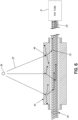
- Each opening 56 has a diameter that is greater than the combined diameters of the light guide fibers 44, thereby forming an air gap between the inner diameter of the crystal and the light guide fibers. This air gap allows the light guide fibers 44 to move freely within the opening 56 with random fiber to fiber spacing, as illustrated in Fig. 9 .
- gauge 30 also includes a plurality of flexible tubes 60 extending between and connecting the primary scintillating crystals 42. Tubes 60 are located between each of the scintillating crystals 42 to maintain the spacing between the crystals. Tubes 60 may be made of spring-reinforced PVC tubing, or another similar flexible material, to allow the tubes to flex within housing 34. Light guide fibers 44 pass through tubes 60 and scintillating crystals 42 within housing 34. Tubes 60 have an inner diameter that is coaxial with openings 56 in scintillating crystals 42 to continue the air gap surrounding the light guide fibers 44 from the crystals through the tubes.
- Primary scintillating crystals 42 are coupled to light guide fibers 44 through the air gap, with scintillating light flashes 46 passing through the air gap to impinge on the light guide fibers.
- tubes 60 are attached at each end to the adjacent scintillating crystals 42 using spring clamps 64. Flexible tubes 60 allow the series of scintillating crystals 42 to flex multi-directionally with the bending of housing 34.
- a first one of the tubes 60 is attached to a mounting flange 70 by a spring clamp 64.
- Mounting flange 70 connects the proximal end of the scintillator assembly to gauge housing 34.
- Light guide fibers 44 extend through mounting flange 70.
- a ferrule 72 couples the proximal, common ends of the light guide fibers 44 to the light sensor 12.
- the distal-most tube 60 at the opposite end of the spaced crystals 42 from mounting flange 70, remains unattached adjacent the closed end of housing 34. Retaining the distal end of the scintillating assembly unattached within the housing 34 allows the series of scintillating crystals 42 and tubes 60 to flex with the bending of the housing.
- the spacing between scintillating crystals 42 can be varied within housing 34 to adjust the sensitivity profile of the gauge 30 and, thus, optimize the linear performance.
- the individual lengths of tubes 60 between the crystals 42 can be varied to obtain the desired spacing between crystals.
- the spacing between crystals 42 can be decreased by decreasing the lengths of tubes 60 in a direction away from the light sensor 12, in order to increase the density of scintillating medium present at increased distance from the light sensor.
- the closer spacing of crystals 42 at the distal end of the gauge 30 compensates for the attenuation that occurs as photons travel greater distances through the light guide fibers 44.
- the selection of the number of scintillating crystals in the scintillator assembly, and the spacing between individual crystals can be customized based upon the vessel geometry and measurement range of the application.
- the length or mass of the individual crystals 42 may be increased, as the distance from the light sensor 12 increases.
- the mass of the crystals 42 can be varied by expanding the longitudinal length of the individual crystals in order to increase the overall density of the scintillating crystal medium.
- the increased size of the crystals enables more scintillating light to be absorbed and transmitted to light guide fibers 44 at the greater distances from the light sensor 12, thereby increasing the volume of photons that are transmitted from the distal ends of the light guide fibers to the light sensor.
- Figs. 14A and 14B illustrate a second exemplary embodiment for gauge 30.
- the primary scintillator is composed of a bundle of scintillating fibers 80.
- the primary scintillating fibers 80 may be interlaced between the light guide fibers 44 as shown or otherwise positioned to extend amongst the light guide fibers through the opening or air gap within housing 34.
- the primary scintillating fibers 80 and the light guide fibers 44 are mounted within housing 34 so as to allow the fibers to flex and bend in multiple directions with the flexing of the housing, as shown in Fig. 14B .
- the primary scintillating fibers 80 have a common end that is attached to a housing end plug 82 near the distal end of housing 34, while the opposite end of the primary fibers remains unattached.
- the light guide fibers 44 have a common end that is attached to the mounting flange 70 at the opposite end of housing 34 from plug 82, for coupling light from the fibers into light sensor 12. The opposite, distal ends of the light guide fibers 44 remain unattached at the closed end of housing 34.
- the primary scintillating fibers 80 and the light guide fibers 44 extend between each other through housing 34.
- the primary scintillating fibers 80 and light guide fibers 44 may come in contact with the flexing and movement of housing 34, but contact between the fibers is not necessary for coupling light between the fibers, and transmitting the light to the light sensor.
- Scintillating light 46 is coupled between the primary scintillating fibers 80 and light guide fibers 44 through the air space surrounding the fibers.
- Fig. 15 depicts a third embodiment for gauge 30 in which the primary scintillator is a bundle of scintillating fibers 80.
- the lengths of the primary scintillating fibers 80 in the bundle are varied in order to vary the density of the scintillating medium at different distances within the gauge 30.
- gauge 30 includes fiber bundles having varying thicknesses, i.e. number of fibers of a particular length. The thickness of the primary scintillating fiber bundle 80 is increased in the direction away from the light sensor 12, in order to compensate for the attenuation that occurs within the light guide fibers 44 at greater distances within the gauge.
- Increasing the density of the scintillating medium in the direction away from the light sensor 12 optimizes the linear response of the gauge by increasing the potential number of scintillating photons released for the same quantity of incident radiation 50 upon the fibers.
- the increased number of photons released per quantity of incident radiation increases the intensity of scintillating light traveling in the light guide fibers 44, enabling a minimum threshold of light to reach the light sensor 12 with sufficient intensity to be detected.
- Producing more scintillating light flashes at increased distances from the light sensor 12 improves the linear performance of the gauge 30, as it serves to equalize the number of photons capable of being produced along the length of the gauge from the incident beam of radiation 50.
- three different thicknesses are shown for the primary scintillating fiber bundle 80. However, greater or lesser thicknesses of fiber bundles may be utilized within the gauge 30 to optimize the performance of the gauge.
- expansion room is provided at the unattached ends of both the primary scintillating fibers 80 and the light guide fibers 44, as indicated at 84 for the primary scintillator fibers 80, and at 86 for the light guide fibers 44.
- the expansion room 84, 86 allows both sets of scintillating fibers to bend and flex within the housing.
- the primary scintillating fibers 80 and the light guide fibers 44 are maintained in a non-contacting relationship inside of housing 34, with scintillating light 46 being coupled between the primary scintillating fibers 80 and the light guide fibers 44 through the air space surrounding the fibers.
- Light guide fibers 44 extend through a guide tube 90 which is centered within the primary scintillating fibers 80, to maintain the light guide fibers in a centralized position relative to the primary scintillating fibers, and maximize the exposure of the light guide fibers to the scintillating light 46.
- a sleeve 92 can be incorporated into housing 34 to surround the exterior of the primary scintillating fiber bundle 80. Both guide tube 90 and sleeve 92 are composed of a flexible material so that the tube and sleeve are free to flex with the scintillator assembly within housing 34.
- the primary scintillators both crystals and fiber bundles, are sized so that no one scintillator is longer than the attenuation length of the scintillator medium.
- Longer length gauges are achieved by providing multiple longitudinally spaced scintillator crystals, or by increasing the thickness of the fiber bundle in the longitudinal direction.
- gauge embodiments described herein eliminate the need for a contact coupling between the primary scintillator and light guide in the light path, instead transmitting scintillating light through the open space within the gauge housing.
- Gauge 30 is capable of transmitting light through a non-contact coupling due to the creation of scintillating light of different wavelengths, and the transfer of the light from the primary scintillator to the light guide scintillating fibers through a wave shift between the primary scintillator and the light guide fibers.
- the scintillating light from the primary scintillator can easily pass through the air gap and impinge on the light guide, which in turn scintillates; with the scintillating light in the light guide traveling through the light guide fibers to the common light sensor.
- the dimensions of the individual scintillators, and the spacing between scintillators are variable, and can be customized to optimize the sensitivity and linearity of the gauge.
- the level sensing gauge has been described herein in conjunction with plastic scintillators, due to the longer attenuation lengths of plastic scintillators (2.5 to 4 m).
- inorganic scintillators may also be used in the described embodiments, provided the emitted scintillating light is suitable to excite the desired emissions spectra in the light guide fibers.
- liquid scintillators may be used as primary scintillators in place of solid plastic scintillators in the level sensing gauge.
- a liquid scintillator 94 is contained within a tube 96.
- tube 96 is hermetically sealed, and the liquid scintillator 94 and light guide fibers 44 are free to expand and contract with temperature inside the tube without the need for bellows. Sealed tube 96 may optionally be flexible to allow the tube to bend when utilized in a flexible outer housing embodiment.
- Light guide fibers 44 are fixed at a proximal end to the light sensor 12. The opposite, distal ends of the light guide fibers 44 are centered within end plug 82, with the end plug having sufficient length to contain the light guide fibers under all operating conditions. The light guide fibers 44 may move freely within end plug 82.
- End plug 82 includes barbed fittings (not shown) for adding or removing scintillating material from tube 96, as well as evacuating air and/or adding inert gas.
- the liquid scintillating material will typically occupy most of the volume of the tube 96, with a sufficient void being maintained in the tube to accommodate thermal dimensional changes.
- the mass of the scintillation material remains constant within the tube 96, but the dimensions may vary with temperature.
- Tube 96 is hermetically sealed to prevent oxygen from infiltrating the tube and degrading the efficacy of the liquid scintillator.
- Tube 96 which may be comprised of coiled rubber or a similar material, is sealed at one end to end plug 82 and at a second end to mounting flange 70.
- Outer gauge housing 34 encloses sealed tube 96, and is attached at one end to the photo multiplier tube housing and at a second end to end plug 82.
- a free-flowing solid scintillating material 98 may be used as a primary scintillator, as depicted in gauge 33 in Fig. 17B .
- the free-flowing solid scintillating material 98 is comprised of particles or pellets which may be of varying sizes and shapes, such as spherical or cylindrical, and which may be composed of a polystyrene or similar material.
- the scintillating pellets may be retained in a container, such as tube 96 shown in Fig. 17B .
- tube 96 may be flexible or rigid, and does not require hermetic sealing.
- the pellets are sized relative to the tube to enable the free-flowing pellets to be poured into the tube. Inside the container, the scintillating pellets surround the light guide fibers 44, to pass scintillating light from the pellets to the fibers.
- alternative containment structures either flexible or non-flexible, may be used for retaining the free-flowing scintillating pellets.
- the scintillator powder may be contained within a structure such as tube 96.
- the tube does not require air-tight sealing, and may or may not be flexible depending upon whether the scintillator will be used in a flexible gauge housing.
Landscapes
- Physics & Mathematics (AREA)
- Electromagnetism (AREA)
- General Physics & Mathematics (AREA)
- Thermal Sciences (AREA)
- Fluid Mechanics (AREA)
- Health & Medical Sciences (AREA)
- Life Sciences & Earth Sciences (AREA)
- High Energy & Nuclear Physics (AREA)
- Molecular Biology (AREA)
- Spectroscopy & Molecular Physics (AREA)
- Measurement Of Radiation (AREA)
- Measurement Of Levels Of Liquids Or Fluent Solid Materials (AREA)
Description
- The present invention relates to radiant energy and, more particularly, to the use of radiant energy in a level sensing gauge.
- In many industrial environments, it is necessary to detect the level of product in a holding tank or bin. Level sensors are typically attached to the holding tank or bin, and electrically connected to remote gauges at a control room or other central location, where technicians or control systems may monitor the status of the bins to provide the appropriate process control. Various technologies have been developed for level sensing. These include various contact sensing technologies using floats or drop weights, as well as various non-contact technologies, such as reflecting electromagnetic radiation or ultrasonic vibrations from the surface of the product in the bin to determine the height of the product. In some applications, it is particularly important to move the sensor away from the product. For example, in a foundry where the level of a hot melt of steel or ore is to be level sensed, it is particularly important to keep the level sensor a safe distance from the hot melt. In these applications, nuclear level sensing gauges are used.
- In a nuclear level sensing gauge, a source of nuclear radiation is positioned on one side of the bin to be level sensed. A nuclear radiation detector is placed on the opposite side of the bin. The radiation exiting the source is in the shape of a wide, generally vertically dispersed beam, directed toward the interior of the bin. The product in the bin substantially absorbs the radiation that impinges upon it. If, however, the bin is not full of product, some part of the beam of radiation from the source passes through the bin and irradiates the radiation detector on the opposite side of the bin from the radiation source. Because the product in the bin substantially absorbs the radiation that impinges upon it, thus reducing the amount of the radiation beam passing through the bin, the amount of radiation stimulating the radiation detector is inversely proportional to the amount of product in the bin. The radiation reaching the detector creates scintillating light flashes in the detector. The number of light flashes is proportional to the intensity of the incident radiation. A high sensitivity light sensor converts the light flashes into electrical pulses, which are amplified and evaluated by electronics to produce a measurement of the amount of product in the bin.
- Traditionally, nuclear level sensing gauges have used an elongated scintillating crystal as a radiation detector. The scintillating crystal produces photons of light when exposed to nuclear radiation from a radiation source. The number of photons produced is related to the amount of radiation impinging on the crystal. A photomultiplier tube (PMT), used as a light sensor, is coupled to an end of the crystal. The PMT detects photons of light emanating from the scintillating crystal, and produces a signal indicative of the amount of radiation impinging on the crystal and, thus, the level of product in the bin. This type of sensor is discussed in
U.S. Pat. Nos. 3,884,288 ,4,481,595 ,4,651,800 ,4,735,253 ,4,739,819 and5,564,487 . - Nuclear level sensing gauges have also been developed which utilize a bundle of one or more scintillating fibers as the radiation detector in place of a scintillating crystal. The scintillating fiber bundle may be directly coupled to a PMT, or coupled to a PMT via a light guide, which permits the PMT and amplifying electronics to be positioned remotely from the fiber bundle. The use of scintillating fibers yields substantial improvements in cost, performance, and ease of use; as well as size and sensitivity, as compared to gauges which use a scintillating crystal. Specifically, compared to a scintillating crystal, the scintillating fibers are lightweight, can be easily coiled for shipment, and are easily cut to the desired lengths. Scintillating fibers can be readily curved to match the curvature of a particular bin, whereas crystals are rigid and difficult to custom manufacture. Also, scintillating fibers have better internal reflection characteristics than crystals, meaning that fiber scintillating detectors can be made longer with less loss than crystal scintillating detectors. Finally, a bundle of one or more fibers can have substantially less heat capacity than the corresponding crystal, meaning the bundle is more readily cooled.
- Unfortunately, both crystals and fibers exhibit light intensity losses when manufactured in long lengths.
Fig. 1 illustrates the decay of light intensity as a function of the distance of travel from a scintillation source through a medium, and the definition of the "attenuation length" L (1/e) of a medium, which is defined as the distance that light can be transmitted through a medium before the light intensity is reduced to 1/e of its intensity at its origin. A fiber bundle typically has an attenuation length of about 2.5 meters. As can be seen from theFig. 1 curve of light intensity vs. distance of travel, light loss is relatively severe at distances longer than the attenuation length, and nonlinear. However, fiber bundles and crystals have been used commercially at long lengths, up to 10 feet for crystals and 12 feet or longer for fiber bundles. Crystals are practically limited to approximately 10 foot lengths because of the difficulty of manufacturing bars in longer sizes. Fibers are not practically limited by manufacturing constraints, but are constrained by the attenuation length of the polystyrene medium used to make the fibers. - Engineers, confronting the limited lengths of scintillating crystals, have created serialized devices that use multiple crystals for level sensing.
Fig. 2 shows a typical prior art arrangement of this kind, in which a plurality of scintillatingcrystals 14 are placed in a serial fashion adjacent a bin opposite to a radiation source S, each crystal stimulating aphotomultiplier tube 12 which is coupled toelectronic amplifiers 10. The output of thevarious amplifiers 10 is then coupled tosummation electronics 20. Eachcrystal 14 has a length less than the attenuation length of the crystal medium, but the serially positioned crystals have a collective length Lt that can be substantially greater than the attenuation length.Fig. 3 shows an alternative, serialized arrangement ofcrystals 14 that has been used in installations where it is desired to move thephotomultiplier tubes 12 remote from thecrystals 14. In this arrangement, alight guide 18 couples light from eachcrystal 14 to eachPMT 12. As inFig. 2 , the crystals are generally cut to a length less than the attenuation length of the crystal medium, but have a collective length Lt that can be substantially longer. While the arrangements illustrated inFigs. 2 and3 facilitate longer length applications, these gauges are highly complex and costly, due to the replication of thePMT 12 andelectronics 10, and the requirement for asummation electronics unit 20. - In order to overcome the problems, cost, and complexity of prior nuclear level sensing gauges, Applicants, in
U.S. Patent Application Serial No. 13/798,179 , published asUS 2014/0264040 A1 , disclose the use of a nuclear level sensing gauge having a plurality of scintillators, positioned in a serial fashion, adjacent the product in a bin. The scintillators are positioned on the opposite side of the bin from the nuclear source. As described therein, and shown inFig. 4 , the level sensing gauge uses a plurality oflight guides 18 to couple light from the scintillators (eithercrystals 14 or fiber bundles 16) to a common light sensor orPMT 12, so that the common light sensor detects light generated in two or more scintillators. Accordingly, the number of photons generated in the scintillators is measured by a single light sensor, producing a measure of radiation-absorbing product in the bin, without the cost and complexity of multiple PMTs and amplifying electronics, as in the previous gauges. - While the use of a single, common light sensor greatly reduces the cost and complexity of the level sensing gauge, the rigidity of
crystals 14 andlight guides 18 in the gauge shown inFig. 4 can limit the available placement of the gauge relative to bins or vessels having curved or complex shapes. Heretofore, gauges have typically been enclosed in a rigid housing, such as stainless steel, to provide protection from harsh operating conditions, and prevent movement or distortion in the optical couplings between the scintillator, light guide and light sensor. Additionally, in the prior gauges intimate contact has been required between the scintillator and light guide. This coupling contact has been required to facilitate collection of as many of the scintillation light flashes as possible, while reducing losses at the optical interfaces. Light guides have been cemented or otherwise securely affixed to the scintillators to optically couple the scintillators and light guides. However, tight, durable contact couplings can be difficult to assemble in the field, due to the harsh operating environment of many nuclear gauge applications. Additionally, the contact couplings in the light path may degrade over time due to movement or the harsh environment, adversely affecting operation of the gauge. - Measurement applications also may dictate a more flexible gauge in order to conform the gauge to the curvature of the bin or vessel being measured. For example, it can be desirable for the gauge to spiral down the exterior of a vessel in order to more accurately measure the contents of the vessel. While gauges have been developed with some degree of flexibility, this flexibility has been limited due to the need to maintain coupling contact between the scintillator and light guide. Prior gauges have attempted to couple the scintillator and light guide through an air gap, but the air gap can fill with water and freeze, causing refraction of the light and loss of output. Accordingly, to accommodate vessels of various shapes, while maintaining a high sensitivity profile, it is desirable to have a nuclear level sensing gauge with increased flexibility that can bend in three dimensions in order to conform the gauge to the shape of the product bin or vessel. Additionally, it is desirable to have a nuclear level sensing gauge that does not require coupling contact between the scintillator and light guide in order to transfer light from the scintillating detectors to the light sensor.
-
US 2015/0014547 A1 describes a nuclear level sensing gauge comprising two or more scintillators arranged in series relative to one another and optical coupling elements arranged between the scintillators. At least one of the coupling elements is a mechanically flexible element, which includes a bundle of light conducting fibres. - The nuclear level sensing gauges described herein improve upon prior gauges by combining the flexibility of scintillating fibers, with low-cost, plastic scintillating crystals, to provide a longer, flexible, linear, level detector that interfaces with a single, common light sensor and electronics. In the gauges described herein, flexible scintillating fibers are used as light guides for transferring gamma-radiation produced scintillations from primary scintillators, which may be scintillating crystals or fibers, to a common light sensor. The gauges described herein incorporate all the scintillating components into a flexible housing that provides protection in harsh operating conditions, seals out ambient light, and allows the gauge to be manipulated and maintained in a flexed position.
- The invention is defined in appended
claim 1. Further preferred aspects of the invention are defined in the dependent claims. - The objects and advantages of the present invention shall be made further apparent from the accompanying drawings and the description thereof.
- The above advantages and features of the invention and embodiments thereof will be further apparent from the following drawings and detailed description, in which:
-
Fig. 1 illustrates the loss of light intensity through a medium as a function of distance from the light source, and the definition of the attenuation length L(1/e); -
Fig. 2 illustrates a prior art nuclear level sensing gauge using a plurality of scintillating crystals arranged in a serialized fashion; -
Fig. 3 illustrates a prior art nuclear level sensing gauge using a plurality of scintillating crystals arranged in a serialized fashion, and light guides to convey photons from the crystals to a plurality of remote photomultipler tubes and amplifying electronics; -
Fig. 4 illustrates a prior art nuclear level sensing gauge using a plurality of scintillators arranged with light guides coupling photons to a common photomultiplier tube and amplifying electronics; -
Fig. 5A is a schematic depiction of a storage vessel and a nuclear level sensing gauge for measuring product levels in the vessel; -
Fig. 5B is a cross-sectional view of the storage vessel and nuclear level sensing gauge ofFig. 5A , taken alongline 5B-5B; -
Fig. 6 is a diagrammatic, cross-sectional view of the radiation detection scheme of the nuclear level sensing gauges of the invention; -
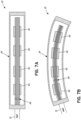
Fig. 7A is a side sectional view of a first exemplary embodiment of a nuclear level sensing gauge; -
Fig. 7B is a side sectional view of the nuclear level sensing gauge embodiment ofFig. 7A , showing the gauge in a flexed condition; -
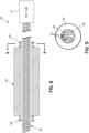
Fig. 8 is a more detailed, side sectional view of a primary scintillating crystal and wave guide fibers for the embodiment shown inFig. 7A ; -
Fig. 9 is a cross-sectional view of a primary scintillating crystal and light guide fibers ofFig. 8 , taken along line 9-9 ofFig. 8 ; -
Fig. 10 is a more detailed, side view of a pair of primary scintillating crystals and connectors, shown in a disassembled position; -
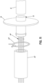
Fig. 11 is a more detailed, side view of a mounting flange at the proximal end of the housing, shown in an exploded, disassembled position; -
Fig. 12 is a side cross-sectional view of the first nuclear level sensing gauge embodiment, depicting variable spacing between the primary scintillating crystals; -
Fig. 13 is a more detailed, side, cross-sectional view, similar toFig. 12 , depicting variable spacing between a plurality of primary scintillating crystals and tube spacers between the crystals; -
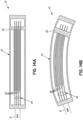
Fig. 14A is a side cross-sectional view of a second exemplary embodiment of a nuclear level sensing gauge; -
Fig. 14B is a side cross-sectional view of the nuclear level sensing gauge ofFig. 14A , showing the gauge in a flexed condition; -
Fig. 15 is a side cross-sectional view of a third exemplary embodiment of a nuclear level sensing gauge, depicting variable thickness in a primary scintillating fiber bundle; -
Fig. 16 is a perspective view of a portion of an alternative, cladded optical fiber; and -
Fig. 17A is a side cross-sectional view of an alternative level sensing gauge embodiment for a liquid primary scintillator, not being covered by the claims; and -
Fig. 17B is a side cross-sectional view of an alternative level sensing gauge embodiment for a free-flowing solid primary scintillator, not being covered by the claims. - Referring now to the drawing figures, in which like numbers indicate like elements throughout the views,
Figs. 5A and 5B illustrate a first embodiment for a nuclearlevel sensing gauge 30, shown attached to a vessel orbin 32, for measuring the level of product in the bin.Gauge 30 includes ahousing 34 enclosing the scintillating components of the gauge.Housing 34 is an elongated tube, which may optionally be formed of a flexible material, which is sufficiently resilient to provide protection for the scintillating components from harsh operating conditions.Housing 34 also prevents ambient light from penetrating into thegauge 30. Examples of suitable materials forhousing 34 include corrugated stainless steel tubing with a rubberized outer wall, and braided nylon for abrasion protection.Housing 34 is attached to the exterior ofbin 32 on the opposite side of the bin from aradiation source 36. In the measurement application shown, tworadiation sources 36 are utilized to accommodate alonger length gauge 30. However, any number of radiation sources may be utilized with thegauge 30, depending upon the vessel size, measurement range, sensitivity profile, and other requirements of the measurement application. - Referring now to
Fig. 6 , in the embodiments described below, light from aprimary scintillator 40 is coupled to acommon light sensor 12 using alight guide 44 which may be composed of one or more scintillating fibers. In a typical application, thelight guide 44 may comprise a bundle having approximately 50 scintillating fibers. Theprimary scintillator 40 generates scintillating light 46 in response to incident ionizinggamma radiation 50 from theradiation source 36. In a first embodiment,light guide fibers 44 may be comprised of a PVT or polystyrene material. In this embodiment, scintillating light fromprimary scintillator 40 is absorbed by the lightguide scintillating fibers 44, which in turn produce photons ofscintillating light 52, as depicted inFig. 6 . Theprimary scintillator 40 produces UV photons in response to absorbing the incident gamma radiation fromsource 36. The light guide fibers convert the UV radiation from theprimary scintillator 40 to photons in the blue and/or green spectrum. Although not shown, thelight guide fibers 44 may also create scintillating light from anygamma radiation particles 50 that impinge directly upon the light guide fibers. A portion of the light guide scintillating light will be trapped within thelight guide fibers 44 and transmitted, as indicated at 54, to thelight sensor 12 for collection, using the total internal reflection (TIR) characteristics of the light guide fibers. - In a second embodiment,
light guide fibers 44 may be comprised of one or moreoptical fibers 58 as depicted inFig. 16 . In this embodiment,light guide fibers 58 may be comprised of a cladded acrylic or polystyrene material.Optical fibers 58 include acentral core 62 and a substantially annular,outer cladding layer 66 circumferentially surrounding the core. Thecore 62 is comprised of a clear (undoped) polystyrene or, alternatively, a clear (undoped) PMMA (acrylic). Thecladding 66 is comprised of a polystyrene or acrylic that is dye-doped with a fluorescent dye. Thecladding 66 is thin, typically having a thickness of about 5-10 µm. The dye used to dope the cladding may be one of blue, green, red, and yellow. -
Optical fibers 58 may be any length depending on the particular application. In the level sensing gauge, UV particles generated byprimary scintillator 40 traverse a short distance through an air gap to impinge on the outer, cladded surface offibers 58. The impinging UV particles are absorbed by the cladding and wave shifted to lower energy, longer wavelength photons. The longer wavelength photons (typically blue) are captured incore 62 and transmitted through the core tolight sensor 12. Shifting incident UV photons to the blue and/or green spectrum at the cladded surface of a clear polystyrene oracrylic fiber 58 allows the photons to be transmitted greater distances to the light sensor. Thelight sensor 12 counts the number of light flashes (photons) within thelight guide fibers 44, and converts the number into an electrical pulse indicative of the number of light flashes and, thus, the level of product in the bin. As described herein, thecommon light sensor 12 may be any type of known light sensing circuitry and associated electronics, including a photomultipler tube (PMT) or photodiode array. - In a first exemplary] embodiment, shown in
Figs. 7A and 7B , nuclearlevel sensing gauge 30 includes a hybrid solid crystal/fiber bundle scintillator assembly, in which the primary scintillator, in the form of a plurality of solidscintillating crystals 42, is combined with alight guide 44, composed of one or more scintillating fibers. The hybrid solid crystal/fiber bundle scintillator assembly provides for greater flexibility in the gauge with a single,common light sensor 12, while alleviating the attenuation problems associated with previous scintillating fiber bundle gauges. In one exemplary application, the primaryscintillating crystals 42 are plastic scintillators composed of polyvinyl toluene, which produces UV light (λ = ~380nm) in response to absorption of gamma radiation fromradiation source 36. In this exemplary application, thelight guide fibers 44 are composed of polystyrene, which produces blue light (λ = ~425 nm) in response to absorption of either gamma radiation fromsource 36, or scintillating UV light from theprimary scintillators 42. Alternatively, as described above,light guide fibers 44 may be composed of a PMMA (acrylic) core with a dye-doped cladding. In alternative embodiments, theprimary scintillators 42 may also be composed of polystyrene to release blue photons, which will be absorbed and waveshifted to green photons by the scintillating light guide fibers prior to detection bylight sensor 12. - As shown in
Figs. 7A and 7B , in this first embodiment the primary scintillator is composed of a plurality of individualscintillating crystals 42 in a spaced relationship along the longitudinal length ofhousing 34. As shown in greater detail inFigs. 8 and 9 , each of thescintillating crystals 42 includes anopening 56 through which thelight guide fibers 44 extend. Eachopening 56 has a diameter that is greater than the combined diameters of thelight guide fibers 44, thereby forming an air gap between the inner diameter of the crystal and the light guide fibers. This air gap allows thelight guide fibers 44 to move freely within theopening 56 with random fiber to fiber spacing, as illustrated inFig. 9 . - As shown in
Figs. 8-11 , in thisembodiment gauge 30 also includes a plurality offlexible tubes 60 extending between and connecting the primaryscintillating crystals 42.Tubes 60 are located between each of thescintillating crystals 42 to maintain the spacing between the crystals.Tubes 60 may be made of spring-reinforced PVC tubing, or another similar flexible material, to allow the tubes to flex withinhousing 34.Light guide fibers 44 pass throughtubes 60 andscintillating crystals 42 withinhousing 34.Tubes 60 have an inner diameter that is coaxial withopenings 56 inscintillating crystals 42 to continue the air gap surrounding thelight guide fibers 44 from the crystals through the tubes. Primaryscintillating crystals 42 are coupled tolight guide fibers 44 through the air gap, with scintillatinglight flashes 46 passing through the air gap to impinge on the light guide fibers. As shown inFig. 10 ,tubes 60 are attached at each end to the adjacentscintillating crystals 42 using spring clamps 64.Flexible tubes 60 allow the series ofscintillating crystals 42 to flex multi-directionally with the bending ofhousing 34. As shown inFig. 11 , a first one of thetubes 60 is attached to a mountingflange 70 by aspring clamp 64. Mountingflange 70 connects the proximal end of the scintillator assembly to gaugehousing 34.Light guide fibers 44 extend through mountingflange 70. Aferrule 72 couples the proximal, common ends of thelight guide fibers 44 to thelight sensor 12. As shown inFig. 12 , thedistal-most tube 60, at the opposite end of the spacedcrystals 42 from mountingflange 70, remains unattached adjacent the closed end ofhousing 34. Retaining the distal end of the scintillating assembly unattached within thehousing 34 allows the series ofscintillating crystals 42 andtubes 60 to flex with the bending of the housing. - As shown in
Figs. 12 and 13 , the spacing betweenscintillating crystals 42 can be varied withinhousing 34 to adjust the sensitivity profile of thegauge 30 and, thus, optimize the linear performance. The individual lengths oftubes 60 between thecrystals 42 can be varied to obtain the desired spacing between crystals. In particular, the spacing betweencrystals 42 can be decreased by decreasing the lengths oftubes 60 in a direction away from thelight sensor 12, in order to increase the density of scintillating medium present at increased distance from the light sensor. The closer spacing ofcrystals 42 at the distal end of thegauge 30 compensates for the attenuation that occurs as photons travel greater distances through thelight guide fibers 44. The selection of the number of scintillating crystals in the scintillator assembly, and the spacing between individual crystals, can be customized based upon the vessel geometry and measurement range of the application. - In addition to varying the spacing between crystals, the length or mass of the
individual crystals 42 may be increased, as the distance from thelight sensor 12 increases. The mass of thecrystals 42 can be varied by expanding the longitudinal length of the individual crystals in order to increase the overall density of the scintillating crystal medium. The increased size of the crystals enables more scintillating light to be absorbed and transmitted tolight guide fibers 44 at the greater distances from thelight sensor 12, thereby increasing the volume of photons that are transmitted from the distal ends of the light guide fibers to the light sensor. While the exemplary gauge embodiments are illustrated in the drawing figures with between four and six scintillating crystals, it should be understood that any number of scintillating crystals may be used in the gauge embodiments described herein without departing from the scope of the invention. The number of scintillating crystals used, the length of the individual scintillating crystals, and the spacing between scintillating crystals may vary, with the particular selections depending upon the desired sensitivity profile of the gauge, and the overall measurement range desired for the particular bin or vessel. -
Figs. 14A and 14B illustrate a second exemplary embodiment forgauge 30. In this second embodiment, the primary scintillator is composed of a bundle ofscintillating fibers 80. The primaryscintillating fibers 80 may be interlaced between thelight guide fibers 44 as shown or otherwise positioned to extend amongst the light guide fibers through the opening or air gap withinhousing 34. The primaryscintillating fibers 80 and thelight guide fibers 44 are mounted withinhousing 34 so as to allow the fibers to flex and bend in multiple directions with the flexing of the housing, as shown inFig. 14B . In particular, the primaryscintillating fibers 80 have a common end that is attached to a housing end plug 82 near the distal end ofhousing 34, while the opposite end of the primary fibers remains unattached. Thelight guide fibers 44 have a common end that is attached to the mountingflange 70 at the opposite end ofhousing 34 fromplug 82, for coupling light from the fibers intolight sensor 12. The opposite, distal ends of thelight guide fibers 44 remain unattached at the closed end ofhousing 34. The primaryscintillating fibers 80 and thelight guide fibers 44 extend between each other throughhousing 34. In this embodiment, the primaryscintillating fibers 80 andlight guide fibers 44 may come in contact with the flexing and movement ofhousing 34, but contact between the fibers is not necessary for coupling light between the fibers, and transmitting the light to the light sensor. Scintillatinglight 46 is coupled between the primaryscintillating fibers 80 andlight guide fibers 44 through the air space surrounding the fibers. -
Fig. 15 depicts a third embodiment forgauge 30 in which the primary scintillator is a bundle ofscintillating fibers 80. In this embodiment, the lengths of the primaryscintillating fibers 80 in the bundle are varied in order to vary the density of the scintillating medium at different distances within thegauge 30. In particular,gauge 30 includes fiber bundles having varying thicknesses, i.e. number of fibers of a particular length. The thickness of the primaryscintillating fiber bundle 80 is increased in the direction away from thelight sensor 12, in order to compensate for the attenuation that occurs within thelight guide fibers 44 at greater distances within the gauge. Increasing the density of the scintillating medium in the direction away from thelight sensor 12 optimizes the linear response of the gauge by increasing the potential number of scintillating photons released for the same quantity ofincident radiation 50 upon the fibers. The increased number of photons released per quantity of incident radiation increases the intensity of scintillating light traveling in thelight guide fibers 44, enabling a minimum threshold of light to reach thelight sensor 12 with sufficient intensity to be detected. Producing more scintillating light flashes at increased distances from thelight sensor 12 improves the linear performance of thegauge 30, as it serves to equalize the number of photons capable of being produced along the length of the gauge from the incident beam ofradiation 50. In the exemplary embodiment shown inFig. 15 , three different thicknesses are shown for the primaryscintillating fiber bundle 80. However, greater or lesser thicknesses of fiber bundles may be utilized within thegauge 30 to optimize the performance of the gauge. - As shown in
Fig. 15 , expansion room is provided at the unattached ends of both the primaryscintillating fibers 80 and thelight guide fibers 44, as indicated at 84 for theprimary scintillator fibers 80, and at 86 for thelight guide fibers 44. Theexpansion room scintillating fibers 80 and thelight guide fibers 44 are maintained in a non-contacting relationship inside ofhousing 34, with scintillating light 46 being coupled between the primaryscintillating fibers 80 and thelight guide fibers 44 through the air space surrounding the fibers. -
Light guide fibers 44 extend through aguide tube 90 which is centered within the primaryscintillating fibers 80, to maintain the light guide fibers in a centralized position relative to the primary scintillating fibers, and maximize the exposure of the light guide fibers to thescintillating light 46. Asleeve 92 can be incorporated intohousing 34 to surround the exterior of the primaryscintillating fiber bundle 80. Both guidetube 90 andsleeve 92 are composed of a flexible material so that the tube and sleeve are free to flex with the scintillator assembly withinhousing 34. In the embodiments described above, the primary scintillators, both crystals and fiber bundles, are sized so that no one scintillator is longer than the attenuation length of the scintillator medium. Longer length gauges are achieved by providing multiple longitudinally spaced scintillator crystals, or by increasing the thickness of the fiber bundle in the longitudinal direction. - The gauge embodiments described herein eliminate the need for a contact coupling between the primary scintillator and light guide in the light path, instead transmitting scintillating light through the open space within the gauge housing.
Gauge 30 is capable of transmitting light through a non-contact coupling due to the creation of scintillating light of different wavelengths, and the transfer of the light from the primary scintillator to the light guide scintillating fibers through a wave shift between the primary scintillator and the light guide fibers. The scintillating light from the primary scintillator can easily pass through the air gap and impinge on the light guide, which in turn scintillates; with the scintillating light in the light guide traveling through the light guide fibers to the common light sensor. In the embodiments described herein, the dimensions of the individual scintillators, and the spacing between scintillators, are variable, and can be customized to optimize the sensitivity and linearity of the gauge. The level sensing gauge has been described herein in conjunction with plastic scintillators, due to the longer attenuation lengths of plastic scintillators (2.5 to 4 m). However, inorganic scintillators may also be used in the described embodiments, provided the emitted scintillating light is suitable to excite the desired emissions spectra in the light guide fibers. - Additionally, liquid scintillators, free-flowing solid scintillators, and/or scintillation powders may be used as primary scintillators in place of solid plastic scintillators in the level sensing gauge. According to an example not part of the invention, in a liquid scintillator embodiment for a
gauge 31, as shown inFig. 17A , aliquid scintillator 94 is contained within atube 96. In the liquid embodiment,tube 96 is hermetically sealed, and theliquid scintillator 94 andlight guide fibers 44 are free to expand and contract with temperature inside the tube without the need for bellows.Sealed tube 96 may optionally be flexible to allow the tube to bend when utilized in a flexible outer housing embodiment.Light guide fibers 44 are fixed at a proximal end to thelight sensor 12. The opposite, distal ends of thelight guide fibers 44 are centered withinend plug 82, with the end plug having sufficient length to contain the light guide fibers under all operating conditions. Thelight guide fibers 44 may move freely withinend plug 82.End plug 82 includes barbed fittings (not shown) for adding or removing scintillating material fromtube 96, as well as evacuating air and/or adding inert gas. The liquid scintillating material will typically occupy most of the volume of thetube 96, with a sufficient void being maintained in the tube to accommodate thermal dimensional changes. The mass of the scintillation material remains constant within thetube 96, but the dimensions may vary with temperature.Tube 96 is hermetically sealed to prevent oxygen from infiltrating the tube and degrading the efficacy of the liquid scintillator.Tube 96, which may be comprised of coiled rubber or a similar material, is sealed at one end to endplug 82 and at a second end to mountingflange 70.Outer gauge housing 34 encloses sealedtube 96, and is attached at one end to the photo multiplier tube housing and at a second end to endplug 82. - In an alternative example not part of the invention, a free-flowing solid
scintillating material 98 may be used as a primary scintillator, as depicted ingauge 33 inFig. 17B . In this embodiment, the free-flowing solidscintillating material 98 is comprised of particles or pellets which may be of varying sizes and shapes, such as spherical or cylindrical, and which may be composed of a polystyrene or similar material. The scintillating pellets may be retained in a container, such astube 96 shown inFig. 17B . In the free-flowing solid embodiment,tube 96 may be flexible or rigid, and does not require hermetic sealing. The pellets are sized relative to the tube to enable the free-flowing pellets to be poured into the tube. Inside the container, the scintillating pellets surround thelight guide fibers 44, to pass scintillating light from the pellets to the fibers. In addition to tubes, alternative containment structures, either flexible or non-flexible, may be used for retaining the free-flowing scintillating pellets. - Additionally, in a scintillator powder embodiment, the scintillator powder may be contained within a structure such as
tube 96. In the powder embodiment, the tube does not require air-tight sealing, and may or may not be flexible depending upon whether the scintillator will be used in a flexible gauge housing. - The present invention has been described in connection with several embodiments and some of those embodiments have been elaborated in substantial detail. However, the scope of the invention is not to be limited by these embodiments which are presented as exemplary and not exclusive. The scope of the invention being claimed is set forth by the following claims.
Claims (8)
- A nuclear level sensing gauge (30) for measuring the level of product in a bin (32), the gauge comprising:a source of nuclear radiation (36) positioned adjacent the product in the bin;a housing (34);a plurality of scintillators (40, 42, 80) provided in the housing (34) adjacent the product in the bin and positioned opposite the source of nuclear radiation (50), nuclear radiation from the source passing through the bin and impinging upon the scintillators, causing the scintillators to generate scintillating light (46);light sensing circuitry (12) for detecting light; and characterised in that it further comprises:
an optical fiber (58) for conveying the scintillating light from all of the scintillators to the light sensing circuitry, the scintillating light being transmitted from each of the scintillators and into the optical fiber through an air coupling, the optical fiber emitting light in response to absorption of the scintillating light from the scintillators, the light sensing circuitry collecting the emitted light from the optical fiber to provide a representation of the level of radiation-absorbing product in the bin. - The nuclear level sensing gauge of claim 1, wherein the optical fiber extends through an air gap in at least one scintillator.
- The nuclear level sensing gauge of claim 1, wherein the light sensing circuitry is a single photomultiplier tube (12).
- The nuclear level sensing gauge of claim 1, wherein the housing (34) is comprised of a flexible material, and the housing (34), the scintillators (40, 42, 80), and the optical fiber (58) are capable of flexing into and maintaining a three-dimensional position.
- The nuclear level sensing gauge of claim 1, wherein at least one scintillator is comprised of polyvinyl toluene and the optical fiber is comprised of polystyrene.
- The nuclear level sensing gauge of claim 1, wherein at least one scintillator comprises a bundle of scintillating fibers (80).
- The nuclear level sensing gauge of claim 1, wherein the spacing between the plurality of scintillators varies with the distance of the scintillators from the light sensing circuitry.
- The nuclear level sensing gauge of claim 6, wherein the thickness of the scintillating fiber bundle (80) varies, with the bundle increasing in thickness with increased distance from the light sensing circuitry (12).
Applications Claiming Priority (3)
| Application Number | Priority Date | Filing Date | Title |
|---|---|---|---|
| US15/004,516 US10365381B1 (en) | 2016-01-22 | 2016-01-22 | Flexible nuclear level sensing gauge |
| US201662396861P | 2016-09-20 | 2016-09-20 | |
| PCT/US2017/014491 WO2017127781A1 (en) | 2016-01-22 | 2017-01-23 | Flexible nuclear level sensing gauge |
Publications (2)
| Publication Number | Publication Date |
|---|---|
| EP3405758A1 EP3405758A1 (en) | 2018-11-28 |
| EP3405758B1 true EP3405758B1 (en) | 2023-07-26 |
Family
ID=57966159
Family Applications (1)
| Application Number | Title | Priority Date | Filing Date |
|---|---|---|---|
| EP17703559.9A Active EP3405758B1 (en) | 2016-01-22 | 2017-01-23 | Flexible nuclear level sensing gauge |
Country Status (9)
| Country | Link |
|---|---|
| EP (1) | EP3405758B1 (en) |
| JP (1) | JP6890614B2 (en) |
| KR (1) | KR20180118113A (en) |
| CN (1) | CN109073446A (en) |
| AU (1) | AU2017209447B2 (en) |
| BR (1) | BR112018014830B1 (en) |
| CA (1) | CA3012181C (en) |
| RU (1) | RU2725669C2 (en) |
| WO (1) | WO2017127781A1 (en) |
Families Citing this family (8)
| Publication number | Priority date | Publication date | Assignee | Title |
|---|---|---|---|---|
| US11112370B2 (en) * | 2019-01-04 | 2021-09-07 | The Boeing Company | Reconfigurable backscatter detector |
| CN111442815B (en) * | 2019-01-17 | 2023-12-01 | 上海树诚实业有限公司 | Wide-range isotope liquid level detection synthetic circuit |
| TWI779280B (en) * | 2019-06-03 | 2022-10-01 | 日商英達斯特股份有限公司 | System for removing fine material |
| CN110595571B (en) * | 2019-10-28 | 2024-12-17 | 株洲菲斯罗克光电科技股份有限公司 | Liquid level detection clamp for proton exchange |
| JP7491571B2 (en) * | 2020-12-02 | 2024-05-28 | 学校法人東京医科大学 | Medical Radiation Dose Monitor |
| KR102498370B1 (en) * | 2022-09-29 | 2023-02-10 | 주식회사 미래와도전 | Radiation sensor system for long-distance and real-time spectroscopy to verify spent nuclear fuel |
| JP7869108B2 (en) * | 2022-10-19 | 2026-06-02 | 日立Geベルノバニュークリアエナジー株式会社 | Clearance measuring device and clearance measuring method |
| CN120161498B (en) * | 2025-03-18 | 2026-01-13 | 兰州大学 | A position-sensitive core fiber optic detector and its fabrication method |
Family Cites Families (14)
| Publication number | Priority date | Publication date | Assignee | Title |
|---|---|---|---|---|
| US3884288A (en) | 1973-02-22 | 1975-05-20 | Southwire Co | Method and apparatus for tundish level control |
| US4481595A (en) | 1981-06-19 | 1984-11-06 | Hans Schiessl | Method and apparatus for determining the fill level of containers |
| SE441502B (en) | 1984-03-19 | 1985-10-14 | Asea Ab | NIVAMETERS BY COCILLES FOR STRING |
| SE454146B (en) | 1985-01-07 | 1988-04-11 | Asea Ab | NIVAMET SIZING DEVICE BY CONTINUOUS CASTING |
| EP0209059A3 (en) | 1985-07-16 | 1989-01-25 | Concast Service Union Ag | Process and apparatus for driving a cast strand in a continuous-casting unit |
| US5564487A (en) | 1993-12-17 | 1996-10-15 | Ronan Engineering Company | Continuous casting mold having radiation source for level measurement |
| JP2971358B2 (en) * | 1994-03-23 | 1999-11-02 | 株式会社東芝 | Radiation measurement device |
| US5629515A (en) * | 1994-03-23 | 1997-05-13 | Kabushiki Kaisha Toshiba | Radiation measuring system having scintillation detectors coupled by optical fibers for multipoint measurement |
| CN2690898Y (en) * | 2004-04-20 | 2005-04-06 | 中国辐射防护研究院 | Detector with perforated photoconductive NaI and wavelength conversion fiber |
| RU2377598C2 (en) * | 2008-01-17 | 2009-12-27 | Федеральное государственное унитарное предприятие "Всероссийский научно-исследовательский институт автоматики им. Н.Л. Духова" | Scintillation detector |
| DE102009002816A1 (en) * | 2009-05-05 | 2010-11-11 | Endress + Hauser Gmbh + Co. Kg | Radiometric measuring device |
| DE102011085943A1 (en) * | 2011-11-08 | 2013-05-08 | Endress + Hauser Gmbh + Co. Kg | Scintillation detector for radiometric measuring device, has retroreflection unit that is arranged in end of fiber bundle to perform retroreflection of incident light back to scintillation fiber bundles |
| DE102012100768A1 (en) * | 2012-01-31 | 2013-08-01 | Endress + Hauser Gmbh + Co. Kg | Szintillationdetektor |
| US9921172B2 (en) * | 2013-03-13 | 2018-03-20 | Vega Americas, Inc. | Segmented fiber nuclear level gauge |
-
2017
- 2017-01-23 BR BR112018014830-0A patent/BR112018014830B1/en active IP Right Grant
- 2017-01-23 AU AU2017209447A patent/AU2017209447B2/en active Active
- 2017-01-23 CN CN201780017535.1A patent/CN109073446A/en active Pending
- 2017-01-23 EP EP17703559.9A patent/EP3405758B1/en active Active
- 2017-01-23 CA CA3012181A patent/CA3012181C/en active Active
- 2017-01-23 WO PCT/US2017/014491 patent/WO2017127781A1/en not_active Ceased
- 2017-01-23 JP JP2018557292A patent/JP6890614B2/en active Active
- 2017-01-23 RU RU2018130159A patent/RU2725669C2/en active
- 2017-01-23 KR KR1020187022881A patent/KR20180118113A/en not_active Ceased
Also Published As
| Publication number | Publication date |
|---|---|
| JP2019504330A (en) | 2019-02-14 |
| JP6890614B2 (en) | 2021-06-18 |
| WO2017127781A1 (en) | 2017-07-27 |
| CA3012181C (en) | 2024-01-02 |
| RU2725669C2 (en) | 2020-07-03 |
| RU2018130159A (en) | 2020-02-26 |
| CA3012181A1 (en) | 2017-07-27 |
| CN109073446A (en) | 2018-12-21 |
| KR20180118113A (en) | 2018-10-30 |
| AU2017209447B2 (en) | 2022-02-03 |
| BR112018014830A2 (en) | 2018-12-18 |
| RU2018130159A3 (en) | 2020-04-21 |
| AU2017209447A1 (en) | 2018-08-16 |
| BR112018014830B1 (en) | 2021-02-17 |
| EP3405758A1 (en) | 2018-11-28 |
Similar Documents
| Publication | Publication Date | Title |
|---|---|---|
| CA3012181C (en) | Flexible nuclear level sensing gauge | |
| AU2014275505B2 (en) | Segmented fiber-based nuclear level gauge | |
| JP3327602B2 (en) | Radiation detection optical transmission device | |
| US9158007B2 (en) | Scintillation detector | |
| US5629515A (en) | Radiation measuring system having scintillation detectors coupled by optical fibers for multipoint measurement | |
| US9069084B2 (en) | Optical fiber having a coating, a radiation sensor and a radiation detection apparatus including the optical fiber and a method of making using the same | |
| US20090020705A1 (en) | Fiber Optic Enhanced Scintillator Detector | |
| EP3014302B1 (en) | Detector arrangement for the detection of ionizing radiation and method for operating such a detector arrangement | |
| GB2472574A (en) | Radiation Detector | |
| US20060138330A1 (en) | Flexible liquid-filled ionizing radiation scintillator used as a product level detector | |
| US7132662B2 (en) | Flexible liquid-filled radiation detector scintillator | |
| US20120032087A1 (en) | Light collecting optical fiber, photodetection system, optical coupling structure and radio ray detection system | |
| US10365381B1 (en) | Flexible nuclear level sensing gauge | |
| US11169282B2 (en) | Detection apparatus and method | |
| US8916828B2 (en) | Radiation detection apparatus and method of using same | |
| WO2015056025A1 (en) | Scintillating optical fiber | |
| JP4621821B2 (en) | Condensing fiber, optical detection system, optical coupling structure, and radiation detection unit | |
| CN110687573A (en) | Thallium-doped cesium iodide scintillation crystal radiation detector with exit surface matched with lens group | |
| KR101526798B1 (en) | Detector modules for position emission tomography and the position emission tomography using the detector module | |
| JP2002341041A (en) | Radiation detection optical transmission device | |
| JPH09127246A (en) | Radiation detector |
Legal Events
| Date | Code | Title | Description |
|---|---|---|---|
| STAA | Information on the status of an ep patent application or granted ep patent |
Free format text: STATUS: UNKNOWN |
|
| STAA | Information on the status of an ep patent application or granted ep patent |
Free format text: STATUS: THE INTERNATIONAL PUBLICATION HAS BEEN MADE |
|
| PUAI | Public reference made under article 153(3) epc to a published international application that has entered the european phase |
Free format text: ORIGINAL CODE: 0009012 |
|
| STAA | Information on the status of an ep patent application or granted ep patent |
Free format text: STATUS: REQUEST FOR EXAMINATION WAS MADE |
|
| 17P | Request for examination filed |
Effective date: 20180815 |
|
| AK | Designated contracting states |
Kind code of ref document: A1 Designated state(s): AL AT BE BG CH CY CZ DE DK EE ES FI FR GB GR HR HU IE IS IT LI LT LU LV MC MK MT NL NO PL PT RO RS SE SI SK SM TR |
|
| AX | Request for extension of the european patent |
Extension state: BA ME |
|
| DAV | Request for validation of the european patent (deleted) | ||
| DAX | Request for extension of the european patent (deleted) | ||
| STAA | Information on the status of an ep patent application or granted ep patent |
Free format text: STATUS: EXAMINATION IS IN PROGRESS |
|
| 17Q | First examination report despatched |
Effective date: 20211108 |
|
| GRAP | Despatch of communication of intention to grant a patent |
Free format text: ORIGINAL CODE: EPIDOSNIGR1 |
|
| STAA | Information on the status of an ep patent application or granted ep patent |
Free format text: STATUS: GRANT OF PATENT IS INTENDED |
|
| INTG | Intention to grant announced |
Effective date: 20230222 |
|
| GRAS | Grant fee paid |
Free format text: ORIGINAL CODE: EPIDOSNIGR3 |
|
| GRAA | (expected) grant |
Free format text: ORIGINAL CODE: 0009210 |
|
| STAA | Information on the status of an ep patent application or granted ep patent |
Free format text: STATUS: THE PATENT HAS BEEN GRANTED |
|
| AK | Designated contracting states |
Kind code of ref document: B1 Designated state(s): AL AT BE BG CH CY CZ DE DK EE ES FI FR GB GR HR HU IE IS IT LI LT LU LV MC MK MT NL NO PL PT RO RS SE SI SK SM TR |
|
| REG | Reference to a national code |
Ref country code: CH Ref legal event code: EP |
|
| P01 | Opt-out of the competence of the unified patent court (upc) registered |
Effective date: 20230704 |
|
| REG | Reference to a national code |
Ref country code: DE Ref legal event code: R096 Ref document number: 602017071739 Country of ref document: DE |
|
| REG | Reference to a national code |
Ref country code: IE Ref legal event code: FG4D |
|
| REG | Reference to a national code |
Ref country code: LT Ref legal event code: MG9D |
|
| REG | Reference to a national code |
Ref country code: NL Ref legal event code: MP Effective date: 20230726 |
|
| REG | Reference to a national code |
Ref country code: AT Ref legal event code: MK05 Ref document number: 1592416 Country of ref document: AT Kind code of ref document: T Effective date: 20230726 |
|
| PG25 | Lapsed in a contracting state [announced via postgrant information from national office to epo] |
Ref country code: NL Free format text: LAPSE BECAUSE OF FAILURE TO SUBMIT A TRANSLATION OF THE DESCRIPTION OR TO PAY THE FEE WITHIN THE PRESCRIBED TIME-LIMIT Effective date: 20230726 |
|
| PG25 | Lapsed in a contracting state [announced via postgrant information from national office to epo] |
Ref country code: GR Free format text: LAPSE BECAUSE OF FAILURE TO SUBMIT A TRANSLATION OF THE DESCRIPTION OR TO PAY THE FEE WITHIN THE PRESCRIBED TIME-LIMIT Effective date: 20231027 |
|
| PG25 | Lapsed in a contracting state [announced via postgrant information from national office to epo] |
Ref country code: IS Free format text: LAPSE BECAUSE OF FAILURE TO SUBMIT A TRANSLATION OF THE DESCRIPTION OR TO PAY THE FEE WITHIN THE PRESCRIBED TIME-LIMIT Effective date: 20231126 |
|
| PG25 | Lapsed in a contracting state [announced via postgrant information from national office to epo] |
Ref country code: SE Free format text: LAPSE BECAUSE OF FAILURE TO SUBMIT A TRANSLATION OF THE DESCRIPTION OR TO PAY THE FEE WITHIN THE PRESCRIBED TIME-LIMIT Effective date: 20230726 Ref country code: RS Free format text: LAPSE BECAUSE OF FAILURE TO SUBMIT A TRANSLATION OF THE DESCRIPTION OR TO PAY THE FEE WITHIN THE PRESCRIBED TIME-LIMIT Effective date: 20230726 Ref country code: PT Free format text: LAPSE BECAUSE OF FAILURE TO SUBMIT A TRANSLATION OF THE DESCRIPTION OR TO PAY THE FEE WITHIN THE PRESCRIBED TIME-LIMIT Effective date: 20231127 Ref country code: NO Free format text: LAPSE BECAUSE OF FAILURE TO SUBMIT A TRANSLATION OF THE DESCRIPTION OR TO PAY THE FEE WITHIN THE PRESCRIBED TIME-LIMIT Effective date: 20231026 Ref country code: LV Free format text: LAPSE BECAUSE OF FAILURE TO SUBMIT A TRANSLATION OF THE DESCRIPTION OR TO PAY THE FEE WITHIN THE PRESCRIBED TIME-LIMIT Effective date: 20230726 Ref country code: LT Free format text: LAPSE BECAUSE OF FAILURE TO SUBMIT A TRANSLATION OF THE DESCRIPTION OR TO PAY THE FEE WITHIN THE PRESCRIBED TIME-LIMIT Effective date: 20230726 Ref country code: IS Free format text: LAPSE BECAUSE OF FAILURE TO SUBMIT A TRANSLATION OF THE DESCRIPTION OR TO PAY THE FEE WITHIN THE PRESCRIBED TIME-LIMIT Effective date: 20231126 Ref country code: HR Free format text: LAPSE BECAUSE OF FAILURE TO SUBMIT A TRANSLATION OF THE DESCRIPTION OR TO PAY THE FEE WITHIN THE PRESCRIBED TIME-LIMIT Effective date: 20230726 Ref country code: GR Free format text: LAPSE BECAUSE OF FAILURE TO SUBMIT A TRANSLATION OF THE DESCRIPTION OR TO PAY THE FEE WITHIN THE PRESCRIBED TIME-LIMIT Effective date: 20231027 Ref country code: FI Free format text: LAPSE BECAUSE OF FAILURE TO SUBMIT A TRANSLATION OF THE DESCRIPTION OR TO PAY THE FEE WITHIN THE PRESCRIBED TIME-LIMIT Effective date: 20230726 Ref country code: AT Free format text: LAPSE BECAUSE OF FAILURE TO SUBMIT A TRANSLATION OF THE DESCRIPTION OR TO PAY THE FEE WITHIN THE PRESCRIBED TIME-LIMIT Effective date: 20230726 |
|
| PG25 | Lapsed in a contracting state [announced via postgrant information from national office to epo] |
Ref country code: PL Free format text: LAPSE BECAUSE OF FAILURE TO SUBMIT A TRANSLATION OF THE DESCRIPTION OR TO PAY THE FEE WITHIN THE PRESCRIBED TIME-LIMIT Effective date: 20230726 |
|
| PG25 | Lapsed in a contracting state [announced via postgrant information from national office to epo] |
Ref country code: ES Free format text: LAPSE BECAUSE OF FAILURE TO SUBMIT A TRANSLATION OF THE DESCRIPTION OR TO PAY THE FEE WITHIN THE PRESCRIBED TIME-LIMIT Effective date: 20230726 |
|
| REG | Reference to a national code |
Ref country code: DE Ref legal event code: R097 Ref document number: 602017071739 Country of ref document: DE |
|
| PG25 | Lapsed in a contracting state [announced via postgrant information from national office to epo] |
Ref country code: SM Free format text: LAPSE BECAUSE OF FAILURE TO SUBMIT A TRANSLATION OF THE DESCRIPTION OR TO PAY THE FEE WITHIN THE PRESCRIBED TIME-LIMIT Effective date: 20230726 Ref country code: RO Free format text: LAPSE BECAUSE OF FAILURE TO SUBMIT A TRANSLATION OF THE DESCRIPTION OR TO PAY THE FEE WITHIN THE PRESCRIBED TIME-LIMIT Effective date: 20230726 Ref country code: ES Free format text: LAPSE BECAUSE OF FAILURE TO SUBMIT A TRANSLATION OF THE DESCRIPTION OR TO PAY THE FEE WITHIN THE PRESCRIBED TIME-LIMIT Effective date: 20230726 Ref country code: EE Free format text: LAPSE BECAUSE OF FAILURE TO SUBMIT A TRANSLATION OF THE DESCRIPTION OR TO PAY THE FEE WITHIN THE PRESCRIBED TIME-LIMIT Effective date: 20230726 Ref country code: DK Free format text: LAPSE BECAUSE OF FAILURE TO SUBMIT A TRANSLATION OF THE DESCRIPTION OR TO PAY THE FEE WITHIN THE PRESCRIBED TIME-LIMIT Effective date: 20230726 Ref country code: CZ Free format text: LAPSE BECAUSE OF FAILURE TO SUBMIT A TRANSLATION OF THE DESCRIPTION OR TO PAY THE FEE WITHIN THE PRESCRIBED TIME-LIMIT Effective date: 20230726 Ref country code: SK Free format text: LAPSE BECAUSE OF FAILURE TO SUBMIT A TRANSLATION OF THE DESCRIPTION OR TO PAY THE FEE WITHIN THE PRESCRIBED TIME-LIMIT Effective date: 20230726 |
|
| PG25 | Lapsed in a contracting state [announced via postgrant information from national office to epo] |
Ref country code: IT Free format text: LAPSE BECAUSE OF FAILURE TO SUBMIT A TRANSLATION OF THE DESCRIPTION OR TO PAY THE FEE WITHIN THE PRESCRIBED TIME-LIMIT Effective date: 20230726 |
|
| PLBE | No opposition filed within time limit |
Free format text: ORIGINAL CODE: 0009261 |
|
| STAA | Information on the status of an ep patent application or granted ep patent |
Free format text: STATUS: NO OPPOSITION FILED WITHIN TIME LIMIT |
|
| 26N | No opposition filed |
Effective date: 20240429 |
|
| PG25 | Lapsed in a contracting state [announced via postgrant information from national office to epo] |
Ref country code: SI Free format text: LAPSE BECAUSE OF FAILURE TO SUBMIT A TRANSLATION OF THE DESCRIPTION OR TO PAY THE FEE WITHIN THE PRESCRIBED TIME-LIMIT Effective date: 20230726 |
|
| PG25 | Lapsed in a contracting state [announced via postgrant information from national office to epo] |
Ref country code: MC Free format text: LAPSE BECAUSE OF FAILURE TO SUBMIT A TRANSLATION OF THE DESCRIPTION OR TO PAY THE FEE WITHIN THE PRESCRIBED TIME-LIMIT Effective date: 20230726 |
|
| PG25 | Lapsed in a contracting state [announced via postgrant information from national office to epo] |
Ref country code: MC Free format text: LAPSE BECAUSE OF FAILURE TO SUBMIT A TRANSLATION OF THE DESCRIPTION OR TO PAY THE FEE WITHIN THE PRESCRIBED TIME-LIMIT Effective date: 20230726 |
|
| REG | Reference to a national code |
Ref country code: CH Ref legal event code: PL |
|
| PG25 | Lapsed in a contracting state [announced via postgrant information from national office to epo] |
Ref country code: LU Free format text: LAPSE BECAUSE OF NON-PAYMENT OF DUE FEES Effective date: 20240123 |
|
| PG25 | Lapsed in a contracting state [announced via postgrant information from national office to epo] |
Ref country code: LU Free format text: LAPSE BECAUSE OF NON-PAYMENT OF DUE FEES Effective date: 20240123 |
|
| PG25 | Lapsed in a contracting state [announced via postgrant information from national office to epo] |
Ref country code: BE Free format text: LAPSE BECAUSE OF NON-PAYMENT OF DUE FEES Effective date: 20240131 |
|
| PG25 | Lapsed in a contracting state [announced via postgrant information from national office to epo] |
Ref country code: FR Free format text: LAPSE BECAUSE OF NON-PAYMENT OF DUE FEES Effective date: 20240131 |
|
| PG25 | Lapsed in a contracting state [announced via postgrant information from national office to epo] |
Ref country code: CH Free format text: LAPSE BECAUSE OF NON-PAYMENT OF DUE FEES Effective date: 20240131 |
|
| PG25 | Lapsed in a contracting state [announced via postgrant information from national office to epo] |
Ref country code: FR Free format text: LAPSE BECAUSE OF NON-PAYMENT OF DUE FEES Effective date: 20240131 Ref country code: CH Free format text: LAPSE BECAUSE OF NON-PAYMENT OF DUE FEES Effective date: 20240131 Ref country code: BE Free format text: LAPSE BECAUSE OF NON-PAYMENT OF DUE FEES Effective date: 20240131 |
|
| REG | Reference to a national code |
Ref country code: BE Ref legal event code: MM Effective date: 20240131 |
|
| PG25 | Lapsed in a contracting state [announced via postgrant information from national office to epo] |
Ref country code: BG Free format text: LAPSE BECAUSE OF FAILURE TO SUBMIT A TRANSLATION OF THE DESCRIPTION OR TO PAY THE FEE WITHIN THE PRESCRIBED TIME-LIMIT Effective date: 20230726 |
|
| PG25 | Lapsed in a contracting state [announced via postgrant information from national office to epo] |
Ref country code: BG Free format text: LAPSE BECAUSE OF FAILURE TO SUBMIT A TRANSLATION OF THE DESCRIPTION OR TO PAY THE FEE WITHIN THE PRESCRIBED TIME-LIMIT Effective date: 20230726 |
|
| PG25 | Lapsed in a contracting state [announced via postgrant information from national office to epo] |
Ref country code: IE Free format text: LAPSE BECAUSE OF NON-PAYMENT OF DUE FEES Effective date: 20240123 |
|
| PG25 | Lapsed in a contracting state [announced via postgrant information from national office to epo] |
Ref country code: IE Free format text: LAPSE BECAUSE OF NON-PAYMENT OF DUE FEES Effective date: 20240123 |
|
| PG25 | Lapsed in a contracting state [announced via postgrant information from national office to epo] |
Ref country code: CY Free format text: LAPSE BECAUSE OF FAILURE TO SUBMIT A TRANSLATION OF THE DESCRIPTION OR TO PAY THE FEE WITHIN THE PRESCRIBED TIME-LIMIT; INVALID AB INITIO Effective date: 20170123 |
|
| PG25 | Lapsed in a contracting state [announced via postgrant information from national office to epo] |
Ref country code: HU Free format text: LAPSE BECAUSE OF FAILURE TO SUBMIT A TRANSLATION OF THE DESCRIPTION OR TO PAY THE FEE WITHIN THE PRESCRIBED TIME-LIMIT; INVALID AB INITIO Effective date: 20170123 |
|
| PG25 | Lapsed in a contracting state [announced via postgrant information from national office to epo] |
Ref country code: TR Free format text: LAPSE BECAUSE OF FAILURE TO SUBMIT A TRANSLATION OF THE DESCRIPTION OR TO PAY THE FEE WITHIN THE PRESCRIBED TIME-LIMIT Effective date: 20230726 |
|
| PGFP | Annual fee paid to national office [announced via postgrant information from national office to epo] |
Ref country code: GB Payment date: 20260127 Year of fee payment: 10 |
|
| PGFP | Annual fee paid to national office [announced via postgrant information from national office to epo] |
Ref country code: DE Payment date: 20260128 Year of fee payment: 10 |