EP3405724B1 - Oil distribution in multiple-compressor systems utilizing variable speed - Google Patents
Oil distribution in multiple-compressor systems utilizing variable speed Download PDFInfo
- Publication number
- EP3405724B1 EP3405724B1 EP17741756.5A EP17741756A EP3405724B1 EP 3405724 B1 EP3405724 B1 EP 3405724B1 EP 17741756 A EP17741756 A EP 17741756A EP 3405724 B1 EP3405724 B1 EP 3405724B1
- Authority
- EP
- European Patent Office
- Prior art keywords
- compressors
- compressor
- lead
- oil
- lead compressor
- Prior art date
- Legal status (The legal status is an assumption and is not a legal conclusion. Google has not performed a legal analysis and makes no representation as to the accuracy of the status listed.)
- Active
Links
Images


Classifications
-
- F—MECHANICAL ENGINEERING; LIGHTING; HEATING; WEAPONS; BLASTING
- F25—REFRIGERATION OR COOLING; COMBINED HEATING AND REFRIGERATION SYSTEMS; HEAT PUMP SYSTEMS; MANUFACTURE OR STORAGE OF ICE; LIQUEFACTION SOLIDIFICATION OF GASES
- F25B—REFRIGERATION MACHINES, PLANTS OR SYSTEMS; COMBINED HEATING AND REFRIGERATION SYSTEMS; HEAT PUMP SYSTEMS
- F25B41/00—Fluid-circulation arrangements
- F25B41/40—Fluid line arrangements
- F25B41/42—Arrangements for diverging or converging flows, e.g. branch lines or junctions
-
- F—MECHANICAL ENGINEERING; LIGHTING; HEATING; WEAPONS; BLASTING
- F04—POSITIVE - DISPLACEMENT MACHINES FOR LIQUIDS; PUMPS FOR LIQUIDS OR ELASTIC FLUIDS
- F04B—POSITIVE-DISPLACEMENT MACHINES FOR LIQUIDS; PUMPS
- F04B39/00—Component parts, details, or accessories, of pumps or pumping systems specially adapted for elastic fluids, not otherwise provided for in, or of interest apart from, groups F04B25/00 - F04B37/00
- F04B39/02—Lubrication
- F04B39/0207—Lubrication with lubrication control systems
-
- F—MECHANICAL ENGINEERING; LIGHTING; HEATING; WEAPONS; BLASTING
- F04—POSITIVE - DISPLACEMENT MACHINES FOR LIQUIDS; PUMPS FOR LIQUIDS OR ELASTIC FLUIDS
- F04B—POSITIVE-DISPLACEMENT MACHINES FOR LIQUIDS; PUMPS
- F04B41/00—Pumping installations or systems specially adapted for elastic fluids
- F04B41/06—Combinations of two or more pumps
-
- F—MECHANICAL ENGINEERING; LIGHTING; HEATING; WEAPONS; BLASTING
- F04—POSITIVE - DISPLACEMENT MACHINES FOR LIQUIDS; PUMPS FOR LIQUIDS OR ELASTIC FLUIDS
- F04B—POSITIVE-DISPLACEMENT MACHINES FOR LIQUIDS; PUMPS
- F04B49/00—Control, e.g. of pump delivery, or pump pressure of, or safety measures for, machines, pumps, or pumping installations, not otherwise provided for, or of interest apart from, groups F04B1/00 - F04B47/00
- F04B49/08—Regulating by delivery pressure
-
- F—MECHANICAL ENGINEERING; LIGHTING; HEATING; WEAPONS; BLASTING
- F04—POSITIVE - DISPLACEMENT MACHINES FOR LIQUIDS; PUMPS FOR LIQUIDS OR ELASTIC FLUIDS
- F04B—POSITIVE-DISPLACEMENT MACHINES FOR LIQUIDS; PUMPS
- F04B49/00—Control, e.g. of pump delivery, or pump pressure of, or safety measures for, machines, pumps, or pumping installations, not otherwise provided for, or of interest apart from, groups F04B1/00 - F04B47/00
- F04B49/20—Control, e.g. of pump delivery, or pump pressure of, or safety measures for, machines, pumps, or pumping installations, not otherwise provided for, or of interest apart from, groups F04B1/00 - F04B47/00 by changing the driving speed
-
- F—MECHANICAL ENGINEERING; LIGHTING; HEATING; WEAPONS; BLASTING
- F04—POSITIVE - DISPLACEMENT MACHINES FOR LIQUIDS; PUMPS FOR LIQUIDS OR ELASTIC FLUIDS
- F04C—ROTARY-PISTON, OR OSCILLATING-PISTON, POSITIVE-DISPLACEMENT MACHINES FOR LIQUIDS; ROTARY-PISTON, OR OSCILLATING-PISTON, POSITIVE-DISPLACEMENT PUMPS
- F04C23/00—Combinations of two or more pumps, each being of rotary-piston or oscillating-piston type, specially adapted for elastic fluids; Pumping installations specially adapted for elastic fluids; Multi-stage pumps specially adapted for elastic fluids
- F04C23/001—Combinations of two or more pumps, each being of rotary-piston or oscillating-piston type, specially adapted for elastic fluids; Pumping installations specially adapted for elastic fluids; Multi-stage pumps specially adapted for elastic fluids of similar working principle
-
- F—MECHANICAL ENGINEERING; LIGHTING; HEATING; WEAPONS; BLASTING
- F04—POSITIVE - DISPLACEMENT MACHINES FOR LIQUIDS; PUMPS FOR LIQUIDS OR ELASTIC FLUIDS
- F04C—ROTARY-PISTON, OR OSCILLATING-PISTON, POSITIVE-DISPLACEMENT MACHINES FOR LIQUIDS; ROTARY-PISTON, OR OSCILLATING-PISTON, POSITIVE-DISPLACEMENT PUMPS
- F04C23/00—Combinations of two or more pumps, each being of rotary-piston or oscillating-piston type, specially adapted for elastic fluids; Pumping installations specially adapted for elastic fluids; Multi-stage pumps specially adapted for elastic fluids
- F04C23/008—Hermetic pumps
-
- F—MECHANICAL ENGINEERING; LIGHTING; HEATING; WEAPONS; BLASTING
- F04—POSITIVE - DISPLACEMENT MACHINES FOR LIQUIDS; PUMPS FOR LIQUIDS OR ELASTIC FLUIDS
- F04C—ROTARY-PISTON, OR OSCILLATING-PISTON, POSITIVE-DISPLACEMENT MACHINES FOR LIQUIDS; ROTARY-PISTON, OR OSCILLATING-PISTON, POSITIVE-DISPLACEMENT PUMPS
- F04C28/00—Control of, monitoring of, or safety arrangements for, pumps or pumping installations specially adapted for elastic fluids
- F04C28/08—Control of, monitoring of, or safety arrangements for, pumps or pumping installations specially adapted for elastic fluids characterised by varying the rotational speed
-
- F—MECHANICAL ENGINEERING; LIGHTING; HEATING; WEAPONS; BLASTING
- F04—POSITIVE - DISPLACEMENT MACHINES FOR LIQUIDS; PUMPS FOR LIQUIDS OR ELASTIC FLUIDS
- F04C—ROTARY-PISTON, OR OSCILLATING-PISTON, POSITIVE-DISPLACEMENT MACHINES FOR LIQUIDS; ROTARY-PISTON, OR OSCILLATING-PISTON, POSITIVE-DISPLACEMENT PUMPS
- F04C29/00—Component parts, details or accessories of pumps or pumping installations, not provided for in groups F04C18/00 - F04C28/00
- F04C29/02—Lubrication; Lubricant separation
- F04C29/021—Control systems for the circulation of the lubricant
-
- F—MECHANICAL ENGINEERING; LIGHTING; HEATING; WEAPONS; BLASTING
- F25—REFRIGERATION OR COOLING; COMBINED HEATING AND REFRIGERATION SYSTEMS; HEAT PUMP SYSTEMS; MANUFACTURE OR STORAGE OF ICE; LIQUEFACTION SOLIDIFICATION OF GASES
- F25B—REFRIGERATION MACHINES, PLANTS OR SYSTEMS; COMBINED HEATING AND REFRIGERATION SYSTEMS; HEAT PUMP SYSTEMS
- F25B1/00—Compression machines, plants or systems with non-reversible cycle
- F25B1/10—Compression machines, plants or systems with non-reversible cycle with multi-stage compression
-
- F—MECHANICAL ENGINEERING; LIGHTING; HEATING; WEAPONS; BLASTING
- F25—REFRIGERATION OR COOLING; COMBINED HEATING AND REFRIGERATION SYSTEMS; HEAT PUMP SYSTEMS; MANUFACTURE OR STORAGE OF ICE; LIQUEFACTION SOLIDIFICATION OF GASES
- F25B—REFRIGERATION MACHINES, PLANTS OR SYSTEMS; COMBINED HEATING AND REFRIGERATION SYSTEMS; HEAT PUMP SYSTEMS
- F25B31/00—Compressor arrangements
-
- F—MECHANICAL ENGINEERING; LIGHTING; HEATING; WEAPONS; BLASTING
- F25—REFRIGERATION OR COOLING; COMBINED HEATING AND REFRIGERATION SYSTEMS; HEAT PUMP SYSTEMS; MANUFACTURE OR STORAGE OF ICE; LIQUEFACTION SOLIDIFICATION OF GASES
- F25B—REFRIGERATION MACHINES, PLANTS OR SYSTEMS; COMBINED HEATING AND REFRIGERATION SYSTEMS; HEAT PUMP SYSTEMS
- F25B31/00—Compressor arrangements
- F25B31/002—Lubrication
-
- F—MECHANICAL ENGINEERING; LIGHTING; HEATING; WEAPONS; BLASTING
- F25—REFRIGERATION OR COOLING; COMBINED HEATING AND REFRIGERATION SYSTEMS; HEAT PUMP SYSTEMS; MANUFACTURE OR STORAGE OF ICE; LIQUEFACTION SOLIDIFICATION OF GASES
- F25B—REFRIGERATION MACHINES, PLANTS OR SYSTEMS; COMBINED HEATING AND REFRIGERATION SYSTEMS; HEAT PUMP SYSTEMS
- F25B31/00—Compressor arrangements
- F25B31/002—Lubrication
- F25B31/004—Lubrication oil recirculating arrangements
-
- F—MECHANICAL ENGINEERING; LIGHTING; HEATING; WEAPONS; BLASTING
- F25—REFRIGERATION OR COOLING; COMBINED HEATING AND REFRIGERATION SYSTEMS; HEAT PUMP SYSTEMS; MANUFACTURE OR STORAGE OF ICE; LIQUEFACTION SOLIDIFICATION OF GASES
- F25B—REFRIGERATION MACHINES, PLANTS OR SYSTEMS; COMBINED HEATING AND REFRIGERATION SYSTEMS; HEAT PUMP SYSTEMS
- F25B49/00—Arrangement or mounting of control or safety devices
- F25B49/02—Arrangement or mounting of control or safety devices for compression type machines, plants or systems
- F25B49/022—Compressor control arrangements
-
- F—MECHANICAL ENGINEERING; LIGHTING; HEATING; WEAPONS; BLASTING
- F04—POSITIVE - DISPLACEMENT MACHINES FOR LIQUIDS; PUMPS FOR LIQUIDS OR ELASTIC FLUIDS
- F04C—ROTARY-PISTON, OR OSCILLATING-PISTON, POSITIVE-DISPLACEMENT MACHINES FOR LIQUIDS; ROTARY-PISTON, OR OSCILLATING-PISTON, POSITIVE-DISPLACEMENT PUMPS
- F04C18/00—Rotary-piston pumps specially adapted for elastic fluids
- F04C18/02—Rotary-piston pumps specially adapted for elastic fluids of arcuate-engagement type, i.e. with circular translatory movement of co-operating members, each member having the same number of teeth or tooth-equivalents
- F04C18/0207—Rotary-piston pumps specially adapted for elastic fluids of arcuate-engagement type, i.e. with circular translatory movement of co-operating members, each member having the same number of teeth or tooth-equivalents both members having co-operating elements in spiral form
-
- F—MECHANICAL ENGINEERING; LIGHTING; HEATING; WEAPONS; BLASTING
- F04—POSITIVE - DISPLACEMENT MACHINES FOR LIQUIDS; PUMPS FOR LIQUIDS OR ELASTIC FLUIDS
- F04C—ROTARY-PISTON, OR OSCILLATING-PISTON, POSITIVE-DISPLACEMENT MACHINES FOR LIQUIDS; ROTARY-PISTON, OR OSCILLATING-PISTON, POSITIVE-DISPLACEMENT PUMPS
- F04C23/00—Combinations of two or more pumps, each being of rotary-piston or oscillating-piston type, specially adapted for elastic fluids; Pumping installations specially adapted for elastic fluids; Multi-stage pumps specially adapted for elastic fluids
-
- F—MECHANICAL ENGINEERING; LIGHTING; HEATING; WEAPONS; BLASTING
- F25—REFRIGERATION OR COOLING; COMBINED HEATING AND REFRIGERATION SYSTEMS; HEAT PUMP SYSTEMS; MANUFACTURE OR STORAGE OF ICE; LIQUEFACTION SOLIDIFICATION OF GASES
- F25B—REFRIGERATION MACHINES, PLANTS OR SYSTEMS; COMBINED HEATING AND REFRIGERATION SYSTEMS; HEAT PUMP SYSTEMS
- F25B2400/00—Component parts or details not otherwise provided for in this subclass
- F25B2400/07—Details of compressors or related parts
- F25B2400/075—Details of compressors or related parts with parallel compressors
- F25B2400/0751—Details of compressors or related parts with parallel compressors the compressors having different capacities
-
- F—MECHANICAL ENGINEERING; LIGHTING; HEATING; WEAPONS; BLASTING
- F25—REFRIGERATION OR COOLING; COMBINED HEATING AND REFRIGERATION SYSTEMS; HEAT PUMP SYSTEMS; MANUFACTURE OR STORAGE OF ICE; LIQUEFACTION SOLIDIFICATION OF GASES
- F25B—REFRIGERATION MACHINES, PLANTS OR SYSTEMS; COMBINED HEATING AND REFRIGERATION SYSTEMS; HEAT PUMP SYSTEMS
- F25B2500/00—Problems to be solved
- F25B2500/16—Lubrication
-
- F—MECHANICAL ENGINEERING; LIGHTING; HEATING; WEAPONS; BLASTING
- F25—REFRIGERATION OR COOLING; COMBINED HEATING AND REFRIGERATION SYSTEMS; HEAT PUMP SYSTEMS; MANUFACTURE OR STORAGE OF ICE; LIQUEFACTION SOLIDIFICATION OF GASES
- F25B—REFRIGERATION MACHINES, PLANTS OR SYSTEMS; COMBINED HEATING AND REFRIGERATION SYSTEMS; HEAT PUMP SYSTEMS
- F25B2600/00—Control issues
- F25B2600/02—Compressor control
- F25B2600/025—Compressor control by controlling speed
- F25B2600/0253—Compressor control by controlling speed with variable speed
-
- F—MECHANICAL ENGINEERING; LIGHTING; HEATING; WEAPONS; BLASTING
- F25—REFRIGERATION OR COOLING; COMBINED HEATING AND REFRIGERATION SYSTEMS; HEAT PUMP SYSTEMS; MANUFACTURE OR STORAGE OF ICE; LIQUEFACTION SOLIDIFICATION OF GASES
- F25B—REFRIGERATION MACHINES, PLANTS OR SYSTEMS; COMBINED HEATING AND REFRIGERATION SYSTEMS; HEAT PUMP SYSTEMS
- F25B2700/00—Sensing or detecting of parameters; Sensors therefor
- F25B2700/19—Pressures
- F25B2700/193—Pressures of the compressor
- F25B2700/1932—Oil pressures
-
- Y—GENERAL TAGGING OF NEW TECHNOLOGICAL DEVELOPMENTS; GENERAL TAGGING OF CROSS-SECTIONAL TECHNOLOGIES SPANNING OVER SEVERAL SECTIONS OF THE IPC; TECHNICAL SUBJECTS COVERED BY FORMER USPC CROSS-REFERENCE ART COLLECTIONS [XRACs] AND DIGESTS
- Y02—TECHNOLOGIES OR APPLICATIONS FOR MITIGATION OR ADAPTATION AGAINST CLIMATE CHANGE
- Y02B—CLIMATE CHANGE MITIGATION TECHNOLOGIES RELATED TO BUILDINGS, e.g. HOUSING, HOUSE APPLIANCES OR RELATED END-USER APPLICATIONS
- Y02B30/00—Energy efficient heating, ventilation or air conditioning [HVAC]
- Y02B30/70—Efficient control or regulation technologies, e.g. for control of refrigerant flow, motor or heating
Definitions
- This invention generally relates to multiple-compressor systems and, more particularly, to oil distribution systems used in multiple-compressor systems.
- a multiple-compressor system such as a refrigeration system
- one challenge is to maintain sufficient oil level in each of the compressors whether the compressor is running or not.
- Designing a system capable of moving equal amounts of oil to different compressors is difficult due to variations in the individual compressors and piping configurations to those compressors.
- a particular example of the state of the art with respect to suction gas distribution in a parallel compressor assembly is represented by WIPO patent publication WO2008/081093 (Device For Suction Gas Distribution In A Parallel Compressor Assembly, And Parallel Compressor Assembly), which shows a distribution device for suction gas in systems with two or more compressors.
- a particular example of oil management in systems having multiple compressors is disclosed in U.S. Patent No. 4,729,228 (Suction Line Flow Stream Separator For Parallel Compressor Arrangements).
- the amount of oil distributed is at least partly dependent on the oil available to be drawn into the opening of an oil-supplying compressor such that the oil can then be distributed to one or more downstream oil-receiving compressors in the refrigeration system. It is also dependent on the oil sump pressures in the compressors.
- US 2014/0037483 A1 discloses a method of operating a refrigerant system using a plurality of compressors providing that the method includes separating oil entrained in the refrigerant and returning more of the oil to a lead compressor regardless of whether the lead compressor is operating.
- EP 1 614 983 A2 discloses an air-conditioner including a variable speed compressor and a constant speed compressor, the constant speed compressor being adapted to operate if necessary, in addition to the variable speed compressor when a room is air conditioned by the air conditioner. Suction tubes of both compressors are connected by a bypass tube in which an electromagnetic valve is arranged. According to this prior art after predetermined times the capacity and load of the compressors are checked and eventually the valve is opened for a predetermined time.
- Embodiments of the invention provide an advancement over the state of the art with respect to oil distribution in multiple-compressor systems.
- embodiments of the invention provide a method of operating a multiple-compressor refrigeration system, according to claim 1.
- This method includes the steps of supplying, via a common supply line, refrigerant gas and oil to a plurality of compressors, and attaching an oil flow conduit between adjacent compressors of the plurality of compressors.
- the oil flow conduit is configured to move oil from a compressor with a relatively higher pressure to a compressor with a relatively lower pressure.
- the method further includes controlling the pressure for each of the plurality of compressors by regulating a speed at which each of the plurality of compressors operates in order to maintain a pressure differential between the adjacent compressors to facilitate the flow of oil from the compressor with the relatively higher pressure to the compressor with the relatively lower pressure.
- controlling the pressure for each of the plurality of compressors by regulating a speed at which each of the plurality of compressors operates includes attaching each of the plurality of compressors to a refrigeration system controller.
- supplying refrigerant gas and oil to a plurality of compressors coupled in series may include supplying refrigerant gas and oil to a lead compressor and to one or more non-lead compressors located downstream of the lead compressor.
- at least one of the one or more non-lead compressors has a greater pumping capacity than the lead compressor.
- a first non-lead compressor is located immediately downstream of the lead compressor, the first non-lead compressor having a greater pumping capacity than the lead compressor, and wherein a second non-lead compressor is located immediately downstream of the first non-lead compressor, the second non-lead compressor having a greater pumping capacity than the first non-lead compressor.
- each of the plurality of compressors may have the same pumping capacity. Also, supplying refrigerant gas and oil to a plurality of compressors may require supplying refrigerant gas and oil to a plurality of compressors via a corresponding plurality of inlet supply lines.
- at least one of the plurality of inlet supply lines includes a flow restriction located on an interior portion of the at least one of the plurality of inlet supply lines.
- at least one of the plurality of inlet supply lines includes a portion that protrudes into the common supply line to restrict a flow of refrigerant gas and oil into the at least one of the plurality of inlet supply lines.
- the plurality of inlet supply lines may be arranged to supply more oil to a lead compressor than is supplied to one or more non-lead compressors located downstream of the lead compressor.
- each of the plurality of inlet supply lines is sized to create a pressure differential between adjacent compressors of the plurality of compressors, and the sizes of the plurality of inlet supply lines are configured to produce a higher pressure in the lead compressor than in the non-lead compressors.
- embodiments of the invention provide a refrigeration system with a plurality of compressors connected in series with each other according to claim 9.
- Each compressor has an oil sump located in a gravitational bottom of the compressor, and one or more oil flow conduits coupled between adjacent compressors of the plurality of compressors.
- the oil flow conduits are configured to facilitate a distribution of oil from an upstream compressor to a downstream compressor.
- a common supply line supplies refrigerant and oil to each of the plurality of compressors.
- the plurality of compressors includes a lead compressor and one or more non-lead compressors.
- the common supply line is configured to return more oil to the lead compressor than to the one or more non-lead compressors.
- a controller is coupled to each of the plurality of compressors.
- the controller regulates the speed of each of the plurality of compressors to control oil sump pressures for each of the plurality of compressors such that the lead compressor has a higher oil sump pressure than any of the one or more non-lead compressors in order to facilitate oil distribution from the lead compressor to the one or more non-lead compressors.
- the plurality of compressors includes the lead compressor being located upstream from a first non-lead compressor.
- the controller is configured to operate the lead compressor at a slower speed than the first non-lead compressor in order to maintain the higher pressure in the lead compressor.
- the lead compressor and first non-lead compressor has the same pumping capacity.
- the first non-lead compressor has a greater pumping capacity than the lead compressor.
- a second non-lead compressor may be coupled to, and downstream of, the first non-lead compressor.
- the plurality of compressors comprises a second non-lead compressor coupled to, and downstream of, the first non-lead compressor, and wherein the controller is configured to operate the lead compressor at a slower speed that the first non-lead compressor in order to maintain the higher pressure in the lead compressor.
- each of the plurality of compressors may have an inlet supply line to supply refrigerant and gas from the common supply line.
- at least one inlet supply line includes one of: a portion that protrudes into the common supply line to restrict a flow of refrigerant gas and oil into the at least one inlet supply line; and a flow restriction located on an interior portion of the at least one inlet supply line.
- each of the inlet supply lines is sized to create a pressure differential between adjacent compressors of the plurality of compressors, and the sizes of the inlet supply lines are configured to produce a higher pressure in the lead compressor than in the non-lead compressors.
- the terms “upstream” and “downstream” are used to refer to various compressors in relation to the flow of oil between the compressors.
- the lead compressor receives most of the oil in the circulated refrigerant.
- the lead compressor is the most upstream of the compressors. Oil flows downstream from the lead compressor to the nearest, or adjacent, non-lead compressor. If the system has a third compressor, oil flows downstream, from the aforementioned non-lead compressor nearest the lead compressor, to the next non-lead compressor.
- the system may rely on pressure differentials between the compressors to move the oil, for example from a lead compressor to one or more non-lead compressors.
- the pressure differential provides the driving force for the movement of oil between compressors.
- the size of the inlet piping feeding oil to the compressor affects pressure.
- pressure can also be affected by the pumping capacity of the compressors.
- FIG. 1 provides a schematic illustration of an exemplary multiple-compressor refrigeration system 1 having a plurality of N compressors 6.
- the N compressors 6 of refrigeration system 1 are connected in a parallel circuit having inlet flow line 3 that supplies a flow of refrigerant to the N compressors 6, and outlet flow line 5 that carries compressed refrigerant away from the N compressors 6.
- the flow of refrigerant carries oil entrained within the flow, the oil used to lubricate moving parts of the compressor 6.
- the outlet flow line 5 supplies a condenser 7.
- the condenser 7 includes a fluid flow heat exchanger 9 (e.g. air or a liquid coolant) which provides a flow across the condenser 7 to cool and thereby condense the compressed, high-pressure refrigerant.
- a fluid flow heat exchanger 9 e.g. air or a liquid coolant
- An evaporation unit 11 to provide cooling is also arranged in fluid series downstream of the condenser 7.
- the condenser 7 may feed multiple evaporation units arranged in parallel.
- the evaporation unit 11 includes a shut off liquid valve 13, which, in some embodiments, is controlled by the refrigeration system controller 15 to allow for operation of the evaporation unit 11 to produce cooling when necessitated by a demand load on the refrigeration system 1, or to preclude operation of the evaporation unit 11 when there is no such demand.
- the refrigeration system controller 15 may also be directly connected to each of the N compressors 6.
- the refrigeration system controller 15 may be configured to independently control each of the N compressors 6.
- the refrigeration system controller 15 may be configured to turn compressors 6 on or off, or independently control the speed of each compressor 6 during operation.
- the evaporation unit 11 also includes an expansion valve 17 that may be responsive to, or in part controlled by, a downstream pressure of the evaporation unit 11, sensed at location 19.
- the expansion valve 17 is configured to control the discharge of refrigerant into the evaporation unit 11, wherein due to the evaporation, heat is absorbed to evaporate the refrigerant to a gaseous state thereby creating a cooling/refrigeration effect at the evaporation unit 11.
- the evaporation unit 11 returns the expanded refrigerant in a gaseous state along the inlet flow line 3 to the bank of N compressors 6.
- FIG. 2 illustrates an alternate embodiment of a refrigeration system 100 in which compressor speed is controlled by refrigeration system controller 15 in such a manner as to create sequentially-decreasing pressures from one compressor to the next in order to facilitate the distribution of oil from compressors with relatively higher oil sump pressures to those with relatively lower oil sump pressures.
- FIG. 2 is a schematic view of the refrigeration system 100 which includes lead compressor 102 connected in series with non-lead compressor 104.
- the two compressors 102, 104 have the same pumping capacity.
- the embodiment of FIG. 2 shows only two compressors, however, it should be understood that the scope of the invention allows for the use of more than two compressors in accordance with the general system arrangement shown in FIG. 2 .
- Refrigerant gas is supplied to the two compressors 102, 104 via a common supply line 108. Oil entrained in the refrigerant gas is also returned to the two compressors 102, 104.
- a first inlet supply line 110 carries refrigerant and oil to the lead compressor 102, while a second inlet supply line 112 carries refrigerant and oil to the non-lead compressor 104.
- first inlet supply line 110 and the second inlet supply line 112 intersect the common supply line 108 at a gravitational bottom of the common supply line 108, where the common supply line 108 runs horizontally.
- the inlet supply lines may intersect with the common supply line 108 at locations other than the gravitational bottom.
- Oil is distributed from the lead compressor 102 to the non-lead compressor 104 via oil flow conduit 116.
- the oil flow conduit 116 is attached to a lower portion of each of the two compressors 102, 104, for example to a fitting attached to the compressor housings proximate the oil sump of each compressor 102, 104.
- the systems are designed to return more oil to the lead compressor 102 than to any of the non-lead compressors.
- the first inlet supply line 110 for the lead compressor 102 is larger than the second inlet supply line 112 for the non-lead compressor 104.
- the larger size of the first inlet supply line 110 allows for a greater pressure of refrigerant gas and oil into the lead compressor 102 than to non-lead compressor 104.
- Successively smaller input supply lines could be attached to the non-lead compressors located downstream from the lead compressor 102. These smaller input supply lines result in decreasing pressures in each successive compressor.
- Other piping means could be used to achieve a similar effect with respect to the pressure in the various compressors.
- the system 100 could have multiple compressors with inlet supply lines of the same size where the flow into the inlet supply lines is limited by restrictions placed inside of the inlet supply lines. The greater the restriction, the lower the pressure in the respective compressor. As will be shown below, flows into the inlet supply lines can also be restricted by having the inlet supply line protrude into the interior of the common supply line 108.
- the pressure in the two compressors 102, 104 are also affected by the pumping capacity of the compressors.
- the refrigeration system controller 15 controls the compressor speed to maintain the desired pressure for controlling the flow of oil from the lead compressor 102 to the non-lead compressor 104.
- Increasing the speed of the non-lead compressor 104 increases its pressure drop thereby lowering the pressure in that compressor and increasing the amount of oil it receives from the lead compressor 102.
- decreasing the speed of the lead compressor 102 reduces its pressure drop thereby raising the pressure in that compressor and increasing the amount of oil it supplies to the non-lead compressor 104.
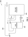
- FIG. 3 illustrates an alternate embodiment of a refrigeration system 200 in which compressor speed is controlled in such a manner as to create sequentially-decreasing pressures from one compressor to the next in order to facilitate the distribution of oil from compressors with relatively higher oil sump pressures to those with relatively lower oil sump pressures.
- the refrigeration system 200 has a lead compressor 202 coupled in series with a non-lead compressor 204.
- a common supply line 208 provides refrigerant gas and oil to the lead compressor 202 via a first inlet supply line 206, and to the non-lead compressor 204 via second inlet supply line 209. Oil is distributed from the lead compressor 202 to the non-lead compressor 204 via oil flow conduit 210.
- the oil flow conduit 210 is attached to a lower portion of each of the two compressors 202, 204, for example to a fitting attached to the compressor housings proximate the oil sump of each compressor 202, 204.
- the first inlet supply lines 206, 209 are of equal size.
- the second inlet supply line 209 has an optional portion 211 (shown in broken lines) that protrudes into an interior portion of the common supply line 208.
- This protruding portion 211 which is oriented perpendicular to the flow of refrigerant and oil, reduces the flow of both into the non-lead compressor 204 reducing the pressure in that compressor.
- the larger capacity and lower oil sump pressure of non-lead compressor 204 facilitates a flow of oil from the lead compressor to non-lead compressor 204 through oil distribution line 210, which is connected to lower portions of the lead and non-lead compressors 202, 204.
- an optional restriction 213 could be used in an interior portion of second inlet supply line 209 to effectively reduce the inner diameter of the second inlet supply line 209, thereby reducing the flow of refrigerant and oil into non-lead compressor 204, which results in a lower pressure in this compressor.
- the flow of oil from the lead compressor 202 to the non-lead compressor 204 can be controlled by regulating the speed, or pump capacity, of the two compressors 202, 204.
- the non-lead compressor 204 compressor is shown as larger than lead compressor 202, indicating its greater pumping capacity than the lead compressor 202.
- the two compressors 202, 204 are scroll compressors
- non-lead compressor 204 would have larger scroll compressor bodies, i.e., designed to compress more refrigerant in a given time period than the compressor bodies of the lead compressor 202.
- the non-lead compressor 204 would also have a larger drive unit, and a larger compressor housing than the lead compressor 202. Therefore, all things being equal, the larger-capacity non-lead compressor 204 would normally have a lower oil sump pressure than the lead compressor 202. Thus, the non-lead compressor 204 could be run at the same speed, or even a lower speed, than the lead compressor 202 while still maintaining a pressure differential sufficient to drive oil from the lead compressor 202 to the non-lead compressor 204.
- the use of portion 211 of second inlet supply line 209 allows even more flexibility in controlling the speeds of the two compressors 202, 204 while still maintaining a pressure differential sufficient for oil distribution from the lead compressor 202 to the non-lead compressor 204.
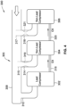
- FIG. 4 is a schematic diagram showing a multiple-compressor refrigeration system 300, according to an embodiment of the invention.
- Refrigeration system 300 includes lead compressor 302 connected in series with first non-lead compressor 304, which is, in turn, connected in series to second non-lead compressor 306.
- first non-lead compressor 304 which is, in turn, connected in series to second non-lead compressor 306.
- the series connections indicates that, regardless of the number of compressors in the system, oil can only flow from an upstream compressor to the next adjacent compressor immediately downstream.
- the first non-lead compressor 304 in which the multi-compressor system 300 includes second non-lead compressor 306 downstream from the first non-lead compressor 304, the first non-lead compressor 304, having a pressure higher than that of the second non-lead compressor 306, distributes oil downstream to second non-lead compressor 306 through a second oil flow conduit 320.
- the first non-lead compressor 304 receives oil from the lead compressor 302 via first oil flow conduit 318. This process can be repeated for however many compressors make up the multi-compressor system 300, where the cascading pressure differential between the compressors allows oil to flow from the lead compressor 302 downstream to non-lead compressors.
- the multiple series-connected compressors distribute oil from the upstream-most compressor sequentially downstream to compressors with progressively lower oil sump pressures. While this design does require adjacent compressors to be running, it will be shown below that there are several different ways of achieving this cascading effect.
- the refrigeration system 300 further includes a suction header arrangement 305 that includes a common supply line 308, a first inlet supply line 312 coupling the lead compressor 302 to the common supply line 308, a second inlet supply line 314 coupling the first non-lead compressor 304 to the common supply line 308, and a third inlet supply line 316 coupling the second non-lead compressor 306 to the common supply line 308.
- lead inlet supply line 312, the first inlet supply line 314, and the second inlet supply line 316 intersect the common supply line 308 at a gravitational bottom of the common supply line 308 where the common supply line 308 runs horizontally.
- a number of suction header arrangements 305 may be used to help achieve the cascading pressures described above.
- first and second restrictions 319, 321 (shown in broken lines) of the second and third inlet supply lines 314, 316, respectively, restrict the flow of refrigerant and oil into those inlet supply lines 314, 316.
- the second protruding portion 317 protrudes farther into the common supply line 308 than the first protruding portion 315.
- the second non-lead compressor 306 will have a lower sump pressure than the first non-lead compressor 304, which will have lower sump pressure than lead compressor 302.
- the second restriction 321 restricts flow more than first restriction 319, which achieves the same result as the first and second protruding portions 315, 317 in terms of refrigerant and oil flow to the three compressors 302, 304, 306.
- the refrigeration system controller 15 (shown in FIG. 1 ) can run the first non-lead compressor 304 at a faster speed than the lead compressor 302 to create a desired pressure differential between those two compressors 302, 304. Further, the refrigeration system controller 15 can run the second non-lead compressor 306 at a faster speed than the first non-lead compressor 304 to create a desired pressure differential between those two compressors 304, 306.
- the arrangement of the inlet supply lines provides flexibility with respect to how compressor speed can be controlled while maintaining the desired pressure differentials.
- the three compressors 302, 304, 306 are the same size and pumping capacity.
- the first non-lead compressor 304 could be larger than the lead compressor 302.
- the second non-lead compressor 306 could be larger or smaller than the first non-lead compressor 304. If the compressor size and pumping capacity increases sequentially downstream from the lead compressor 302, then the pressure differentials could be maintained even if all compressors were run at the same speed, or even if the lead compressor 302 is run at a faster speed than the non-lead compressors 304, 306.
Landscapes
- Engineering & Computer Science (AREA)
- Mechanical Engineering (AREA)
- General Engineering & Computer Science (AREA)
- Physics & Mathematics (AREA)
- Thermal Sciences (AREA)
- Applications Or Details Of Rotary Compressors (AREA)
- Control Of Positive-Displacement Pumps (AREA)
- Compressors, Vaccum Pumps And Other Relevant Systems (AREA)
Description
- This invention generally relates to multiple-compressor systems and, more particularly, to oil distribution systems used in multiple-compressor systems.
- In a multiple-compressor system, such as a refrigeration system, one challenge is to maintain sufficient oil level in each of the compressors whether the compressor is running or not. Designing a system capable of moving equal amounts of oil to different compressors is difficult due to variations in the individual compressors and piping configurations to those compressors. A particular example of the state of the art with respect to suction gas distribution in a parallel compressor assembly is represented by WIPO patent publication
WO2008/081093 (Device For Suction Gas Distribution In A Parallel Compressor Assembly, And Parallel Compressor Assembly), which shows a distribution device for suction gas in systems with two or more compressors. A particular example of oil management in systems having multiple compressors is disclosed inU.S. Patent No. 4,729,228 (Suction Line Flow Stream Separator For Parallel Compressor Arrangements). - Additionally, oil distribution systems for multiple-compressor arrangements are disclosed in
U.S. Patent Pub. No. 2014/0056725, published February 27, 2014 ;U.S. Patent Pub. No. 2014/0037483, published February 6, 2014 ; andU.S. Patent Pub. No. 2014/0037484, published February 6, 2014 , each of which is assigned to the assignee of the present application. - For example, when distributing oil from one compressor to another in in a refrigeration system having multiple compressors, the amount of oil distributed is at least partly dependent on the oil available to be drawn into the opening of an oil-supplying compressor such that the oil can then be distributed to one or more downstream oil-receiving compressors in the refrigeration system. It is also dependent on the oil sump pressures in the compressors.
US 2014/0037483 A1 discloses a method of operating a refrigerant system using a plurality of compressors providing that the method includes separating oil entrained in the refrigerant and returning more of the oil to a lead compressor regardless of whether the lead compressor is operating.EP 1 614 983 A2 - Embodiments of the invention provide an advancement over the state of the art with respect to oil distribution in multiple-compressor systems. These and other advantages of the invention, as well as additional inventive features, will be apparent from the description of the invention provided herein.
- In one aspect, embodiments of the invention provide a method of operating a multiple-compressor refrigeration system, according to
claim 1. This method includes the steps of supplying, via a common supply line, refrigerant gas and oil to a plurality of compressors, and attaching an oil flow conduit between adjacent compressors of the plurality of compressors. The oil flow conduit is configured to move oil from a compressor with a relatively higher pressure to a compressor with a relatively lower pressure. The method further includes controlling the pressure for each of the plurality of compressors by regulating a speed at which each of the plurality of compressors operates in order to maintain a pressure differential between the adjacent compressors to facilitate the flow of oil from the compressor with the relatively higher pressure to the compressor with the relatively lower pressure. - In a particular embodiment, controlling the pressure for each of the plurality of compressors by regulating a speed at which each of the plurality of compressors operates includes attaching each of the plurality of compressors to a refrigeration system controller. Also, supplying refrigerant gas and oil to a plurality of compressors coupled in series may include supplying refrigerant gas and oil to a lead compressor and to one or more non-lead compressors located downstream of the lead compressor. In certain embodiments, at least one of the one or more non-lead compressors has a greater pumping capacity than the lead
compressor. Further, in some embodiments, a first non-lead compressor is located immediately downstream of the lead compressor, the first non-lead compressor having a greater pumping capacity than the lead compressor, and wherein a second non-lead compressor is located immediately downstream of the first non-lead compressor, the second non-lead compressor having a greater pumping capacity than the first non-lead compressor. - Additionally, each of the plurality of compressors may have the same pumping capacity. Also, supplying refrigerant gas and oil to a plurality of compressors may require supplying refrigerant gas and oil to a plurality of compressors via a corresponding plurality of inlet supply lines. In some embodiments, at least one of the plurality of inlet supply lines includes a flow restriction located on an interior portion of the at least one of the plurality of inlet supply lines. In other embodiments, at least one of the plurality of inlet supply lines includes a portion that protrudes into the common supply line to restrict a flow of refrigerant gas and oil into the at least one of the plurality of inlet supply lines. The plurality of inlet supply lines may be arranged to supply more oil to a lead compressor than is supplied to one or more non-lead compressors located downstream of the lead compressor.
- In further embodiments of the method, each of the plurality of inlet supply lines is sized to create a pressure differential between adjacent compressors of the plurality of compressors, and the sizes of the plurality of inlet supply lines are configured to produce a higher pressure in the lead compressor than in the non-lead compressors.
- In another aspect, embodiments of the invention provide a refrigeration system with a plurality of compressors connected in series with each other according to
claim 9. Each compressor has an oil sump located in a gravitational bottom of the compressor, and one or more oil flow conduits coupled between adjacent compressors of the plurality of compressors. The oil flow conduits are configured to facilitate a distribution of oil from an upstream compressor to a downstream compressor. A common supply line supplies refrigerant and oil to each of the plurality of compressors. The plurality of compressors includes a lead compressor and one or more non-lead compressors. The common supply line is configured to return more oil to the lead compressor than to the one or more non-lead compressors. A controller is coupled to each of the plurality of compressors. The controller regulates the speed of each of the plurality of compressors to control oil sump pressures for each of the plurality of compressors such that the lead compressor has a higher oil sump pressure than any of the one or more non-lead compressors in order to facilitate oil distribution from the lead compressor to the one or more non-lead compressors. - In a particular embodiment, the plurality of compressors includes the lead compressor being located upstream from a first non-lead compressor. The controller is configured to operate the lead compressor at a slower speed than the first non-lead compressor in order to maintain the higher pressure in the lead compressor. In some embodiments, the lead compressor and first non-lead compressor has the same pumping capacity. In other embodiments, the first non-lead compressor has a greater pumping capacity than the lead compressor. Furthermore, a second non-lead compressor may be coupled to, and downstream of, the first non-lead compressor.
- In certain embodiments, the plurality of compressors comprises a second non-lead compressor coupled to, and downstream of, the first non-lead compressor, and wherein the controller is configured to operate the lead compressor at a slower speed that the first non-lead compressor in order to maintain the higher pressure in the lead compressor. Further, each of the plurality of compressors may have an inlet supply line to supply refrigerant and gas from the common supply line. In a particular embodiment, at least one inlet supply line includes one of: a portion that protrudes into the common supply line to restrict a flow of refrigerant gas and oil into the at least one inlet supply line; and a flow restriction located on an interior portion of the at least one inlet supply line.
- In a further embodiment, each of the inlet supply lines is sized to create a pressure differential between adjacent compressors of the plurality of compressors, and the sizes of the inlet supply lines are configured to produce a higher pressure in the lead compressor than in the non-lead compressors.
- Other aspects, objectives and advantages of the invention will become more apparent from the following detailed description when taken in conjunction with the accompanying drawings.
- The accompanying drawings incorporated in and forming a part of the specification illustrate several aspects of the present invention and, together with the description, serve to explain the principles of the invention. In the drawings:
-
FIG. 1 is a block diagram of a multi-compressor refrigeration system, constructed in accordance with an embodiment of the invention; -
FIG. 2 is a schematic diagram of an exemplary multiple-compressor refrigeration system, constructed in accordance with an embodiment of the invention; -
FIG. 3 is a schematic diagram of another exemplary multiple-compressor refrigeration system, constructed in accordance with an embodiment of the invention; and -
FIG. 4 is a schematic diagram of yet another exemplary multiple-compressor refrigeration system, constructed in accordance with an embodiment of the invention. - While the invention will be described in connection with certain preferred embodiments, there is no intent to limit it to those embodiments. On the contrary, the intent is to cover all alternatives, modifications and equivalents as included within the scope of the invention as defined by the appended claims.
- The following detailed description describes embodiments of the invention as applied in a multi-compressor refrigeration system. However, one of ordinary skill in the art will recognize that the invention is not necessarily limited to refrigeration systems. Embodiments of the invention may also find use in other systems where multiple compressors are used to supply a flow of compressed gas. It should also be noted that, for the sake of convenience, certain embodiments of the invention may be described hereinbelow with respect to their application in systems having multiple scroll compressors for compressing refrigerant. While particular advantages and configurations are shown for scroll compressors, Applicants submit that the scope of the invention is not necessarily limited to scroll compressors, but may find use in a variety of multiple-compressor systems using compressor types other than scroll compressors.
- In the context of this application, the terms "upstream" and "downstream" are used to refer to various compressors in relation to the flow of oil between the compressors. For example, in the embodiments of refrigeration systems described hereinbelow, the lead compressor receives most of the oil in the circulated refrigerant. As such, in the embodiments presented, the lead compressor is the most upstream of the compressors. Oil flows downstream from the lead compressor to the nearest, or adjacent, non-lead compressor. If the system has a third compressor, oil flows downstream, from the aforementioned non-lead compressor nearest the lead compressor, to the next non-lead compressor.
- In multiple-compressor systems in which oil is distributed between compressors, the system may rely on pressure differentials between the compressors to move the oil, for example from a lead compressor to one or more non-lead compressors. In certain system arrangements, the pressure differential provides the driving force for the movement of oil between compressors. There are several factors which may affect the pressure in a given compressor. For example, the size of the inlet piping feeding oil to the compressor affects pressure. Additionally, as will be explained below, pressure can also be affected by the pumping capacity of the compressors.
-
FIG. 1 provides a schematic illustration of an exemplary multiple-compressor refrigeration system 1 having a plurality ofN compressors 6. The N compressors 6 ofrefrigeration system 1 are connected in a parallel circuit havinginlet flow line 3 that supplies a flow of refrigerant to the N compressors 6, andoutlet flow line 5 that carries compressed refrigerant away from theN compressors 6. In certain embodiments, the flow of refrigerant carries oil entrained within the flow, the oil used to lubricate moving parts of thecompressor 6. As shown, theoutlet flow line 5 supplies acondenser 7. In a particular embodiment, thecondenser 7 includes a fluid flow heat exchanger 9 (e.g. air or a liquid coolant) which provides a flow across thecondenser 7 to cool and thereby condense the compressed, high-pressure refrigerant. - An
evaporation unit 11 to provide cooling is also arranged in fluid series downstream of thecondenser 7. In an alternate embodiment, thecondenser 7 may feed multiple evaporation units arranged in parallel. In the embodiment ofFIG. 1 , theevaporation unit 11 includes a shut offliquid valve 13, which, in some embodiments, is controlled by therefrigeration system controller 15 to allow for operation of theevaporation unit 11 to produce cooling when necessitated by a demand load on therefrigeration system 1, or to preclude operation of theevaporation unit 11 when there is no such demand. As shown inFIG. 1 , therefrigeration system controller 15 may also be directly connected to each of theN compressors 6. Therefrigeration system controller 15 may be configured to independently control each of theN compressors 6. Specifically, therefrigeration system controller 15 may be configured to turncompressors 6 on or off, or independently control the speed of eachcompressor 6 during operation. - The
evaporation unit 11 also includes anexpansion valve 17 that may be responsive to, or in part controlled by, a downstream pressure of theevaporation unit 11, sensed atlocation 19. Theexpansion valve 17 is configured to control the discharge of refrigerant into theevaporation unit 11, wherein due to the evaporation, heat is absorbed to evaporate the refrigerant to a gaseous state thereby creating a cooling/refrigeration effect at theevaporation unit 11. Theevaporation unit 11 returns the expanded refrigerant in a gaseous state along theinlet flow line 3 to the bank ofN compressors 6. -
FIG. 2 illustrates an alternate embodiment of arefrigeration system 100 in which compressor speed is controlled byrefrigeration system controller 15 in such a manner as to create sequentially-decreasing pressures from one compressor to the next in order to facilitate the distribution of oil from compressors with relatively higher oil sump pressures to those with relatively lower oil sump pressures.FIG. 2 is a schematic view of therefrigeration system 100 which includeslead compressor 102 connected in series withnon-lead compressor 104. In this embodiment, the twocompressors FIG. 2 shows only two compressors, however, it should be understood that the scope of the invention allows for the use of more than two compressors in accordance with the general system arrangement shown inFIG. 2 . - Refrigerant gas is supplied to the two
compressors common supply line 108. Oil entrained in the refrigerant gas is also returned to the twocompressors inlet supply line 110 carries refrigerant and oil to thelead compressor 102, while a secondinlet supply line 112 carries refrigerant and oil to thenon-lead compressor 104. In the embodiment ofFIG. 2 , firstinlet supply line 110 and the secondinlet supply line 112 intersect thecommon supply line 108 at a gravitational bottom of thecommon supply line 108, where thecommon supply line 108 runs horizontally. In alternate embodiment, the inlet supply lines may intersect with thecommon supply line 108 at locations other than the gravitational bottom. - Oil is distributed from the
lead compressor 102 to thenon-lead compressor 104 viaoil flow conduit 116. Theoil flow conduit 116 is attached to a lower portion of each of the twocompressors compressor lead compressor 102 than to any of the non-lead compressors. - In the embodiment of
FIG. 2 , the firstinlet supply line 110 for thelead compressor 102 is larger than the secondinlet supply line 112 for thenon-lead compressor 104. In this case, the larger size of the firstinlet supply line 110 allows for a greater pressure of refrigerant gas and oil into thelead compressor 102 than tonon-lead compressor 104. Successively smaller input supply lines could be attached to the non-lead compressors located downstream from thelead compressor 102. These smaller input supply lines result in decreasing pressures in each successive compressor. Other piping means could be used to achieve a similar effect with respect to the pressure in the various compressors. For example, thesystem 100 could have multiple compressors with inlet supply lines of the same size where the flow into the inlet supply lines is limited by restrictions placed inside of the inlet supply lines. The greater the restriction, the lower the pressure in the respective compressor. As will be shown below, flows into the inlet supply lines can also be restricted by having the inlet supply line protrude into the interior of thecommon supply line 108. - As stated above, the pressure in the two
compressors FIG. 1 ) controls the compressor speed to maintain the desired pressure for controlling the flow of oil from thelead compressor 102 to thenon-lead compressor 104. Increasing the speed of thenon-lead compressor 104 increases its pressure drop thereby lowering the pressure in that compressor and increasing the amount of oil it receives from thelead compressor 102. Alternatively, decreasing the speed of thelead compressor 102 reduces its pressure drop thereby raising the pressure in that compressor and increasing the amount of oil it supplies to thenon-lead compressor 104. - When used in conjunction with inlet supply line arrangements such as shown in
FIG. 2 , there is some added flexibility with respect to the aforementioned control of compressor speed to maintain the desired pressure differential to facilitate a flow of oil from thelead compressor 102. For example, with the inlet supply line arrangement ofFIG. 2 , it may be possible to operate thelead compressor 102 at the same speed, or even a higher speed, than thenon-lead compressor 104 while maintaining the desired pressure differential. -
FIG. 3 illustrates an alternate embodiment of arefrigeration system 200 in which compressor speed is controlled in such a manner as to create sequentially-decreasing pressures from one compressor to the next in order to facilitate the distribution of oil from compressors with relatively higher oil sump pressures to those with relatively lower oil sump pressures. Therefrigeration system 200 has alead compressor 202 coupled in series with anon-lead compressor 204. Acommon supply line 208 provides refrigerant gas and oil to thelead compressor 202 via a firstinlet supply line 206, and to thenon-lead compressor 204 via secondinlet supply line 209. Oil is distributed from thelead compressor 202 to thenon-lead compressor 204 viaoil flow conduit 210. Theoil flow conduit 210 is attached to a lower portion of each of the twocompressors compressor - In the embodiment of
FIG. 3 , the firstinlet supply lines inlet supply line 209 has an optional portion 211 (shown in broken lines) that protrudes into an interior portion of thecommon supply line 208. This protrudingportion 211, which is oriented perpendicular to the flow of refrigerant and oil, reduces the flow of both into thenon-lead compressor 204 reducing the pressure in that compressor. The larger capacity and lower oil sump pressure ofnon-lead compressor 204 facilitates a flow of oil from the lead compressor tonon-lead compressor 204 throughoil distribution line 210, which is connected to lower portions of the lead andnon-lead compressors portion 211, anoptional restriction 213 could be used in an interior portion of secondinlet supply line 209 to effectively reduce the inner diameter of the secondinlet supply line 209, thereby reducing the flow of refrigerant and oil intonon-lead compressor 204, which results in a lower pressure in this compressor. - However, with or without the
restriction 213 or the protrudingportion 211 of the secondinlet supply line 209, the flow of oil from thelead compressor 202 to thenon-lead compressor 204 can be controlled by regulating the speed, or pump capacity, of the twocompressors FIG. 3 , thenon-lead compressor 204 compressor is shown as larger thanlead compressor 202, indicating its greater pumping capacity than thelead compressor 202. For example, if the twocompressors non-lead compressor 204 would have larger scroll compressor bodies, i.e., designed to compress more refrigerant in a given time period than the compressor bodies of thelead compressor 202. Thenon-lead compressor 204 would also have a larger drive unit, and a larger compressor housing than thelead compressor 202. Therefore, all things being equal, the larger-capacity non-lead compressor 204 would normally have a lower oil sump pressure than thelead compressor 202. Thus, thenon-lead compressor 204 could be run at the same speed, or even a lower speed, than thelead compressor 202 while still maintaining a pressure differential sufficient to drive oil from thelead compressor 202 to thenon-lead compressor 204. The use ofportion 211 of secondinlet supply line 209 allows even more flexibility in controlling the speeds of the twocompressors lead compressor 202 to thenon-lead compressor 204. -
FIG. 4 is a schematic diagram showing a multiple-compressor refrigeration system 300, according to an embodiment of the invention.Refrigeration system 300 includeslead compressor 302 connected in series with firstnon-lead compressor 304, which is, in turn, connected in series to secondnon-lead compressor 306. In the arrangements shown inFIG. 4 , as in the embodiments described above, the series connections indicates that, regardless of the number of compressors in the system, oil can only flow from an upstream compressor to the next adjacent compressor immediately downstream. - In the embodiment of
FIG. 4 , in which themulti-compressor system 300 includes secondnon-lead compressor 306 downstream from the firstnon-lead compressor 304, the firstnon-lead compressor 304, having a pressure higher than that of the secondnon-lead compressor 306, distributes oil downstream to secondnon-lead compressor 306 through a secondoil flow conduit 320. The firstnon-lead compressor 304 receives oil from thelead compressor 302 via firstoil flow conduit 318. This process can be repeated for however many compressors make up themulti-compressor system 300, where the cascading pressure differential between the compressors allows oil to flow from thelead compressor 302 downstream to non-lead compressors. Thus, the multiple series-connected compressors distribute oil from the upstream-most compressor sequentially downstream to compressors with progressively lower oil sump pressures. While this design does require adjacent compressors to be running, it will be shown below that there are several different ways of achieving this cascading effect. - The
refrigeration system 300 further includes asuction header arrangement 305 that includes acommon supply line 308, a firstinlet supply line 312 coupling thelead compressor 302 to thecommon supply line 308, a secondinlet supply line 314 coupling the firstnon-lead compressor 304 to thecommon supply line 308, and a thirdinlet supply line 316 coupling the secondnon-lead compressor 306 to thecommon supply line 308. - In the embodiment shown, lead
inlet supply line 312, the firstinlet supply line 314, and the secondinlet supply line 316 intersect thecommon supply line 308 at a gravitational bottom of thecommon supply line 308 where thecommon supply line 308 runs horizontally. A number ofsuction header arrangements 305 may be used to help achieve the cascading pressures described above. Optional first and second protrudingportions 315, 317 (shown in broken lines) of the second and thirdinlet supply lines inlet supply lines second restrictions 319, 321 (shown in broken lines) of the second and thirdinlet supply lines inlet supply lines FIG. 4 , the second protrudingportion 317 protrudes farther into thecommon supply line 308 than the first protrudingportion 315. As a result, the secondnon-lead compressor 306 will have a lower sump pressure than the firstnon-lead compressor 304, which will have lower sump pressure thanlead compressor 302. Similarly, it can be seen that thesecond restriction 321 restricts flow more thanfirst restriction 319, which achieves the same result as the first and second protrudingportions compressors - Therefore, in the embodiment of
FIG. 4 , while all threecompressors common supply line 308, thecommon supply line 308 delivers more lubricating oil to thelead compressor 302, via the firstinlet supply line 312. However, with or without the optional first andsecond restrictions portions lead compressor 302 to the firstnon-lead compressor 304, and from that compressor to the secondnon-lead compressor 306, can be controlled by regulating the speed, or pump capacity, of the threecompressors - As explained above, the refrigeration system controller 15 (shown in
FIG. 1 ) can run the firstnon-lead compressor 304 at a faster speed than thelead compressor 302 to create a desired pressure differential between those twocompressors refrigeration system controller 15 can run the secondnon-lead compressor 306 at a faster speed than the firstnon-lead compressor 304 to create a desired pressure differential between those twocompressors compressors compressors - In the embodiment of
FIG. 4 , the threecompressors FIG. 3 , the firstnon-lead compressor 304 could be larger than thelead compressor 302. The secondnon-lead compressor 306 could be larger or smaller than the firstnon-lead compressor 304. If the compressor size and pumping capacity increases sequentially downstream from thelead compressor 302, then the pressure differentials could be maintained even if all compressors were run at the same speed, or even if thelead compressor 302 is run at a faster speed than thenon-lead compressors
Claims (15)
- A method of operating a multiple-compressor refrigeration system (1, 100, 200, 300) comprising the steps of:supplying, via a common supply line (108, 208, 308), refrigerant gas and oil to a plurality of compressors (6, 102, 104, 202, 204, 302, 304, 306);attaching an oil flow conduit (116, 210, 318, 320) between adjacent compressors (6, 102, 104, 202, 204, 302, 304, 306) of the plurality of compressors (6, 102, 104, 202, 204, 302, 304, 306), such that the plurality of compressors (6, 102, 104, 202, 204, 302, 304, 306) are coupled in series by said oil flow conduit so that, regardless of the number of compressors in the system, oil can only flow from an upstream compressor to the next adjacent compressor immediately downstream, the oil flow conduit (116, 210, 318, 320) configured to move oil from a compressor (6, 102, 104, 202, 204, 302, 304, 306) with a relatively higher pressure to a compressor (6, 102, 104, 202, 204, 302, 304, 306) with a relatively lower pressure;the method being characterised by controlling the pressure for each of the plurality of compressors (6, 102, 104, 202, 204, 302, 304, 306) by regulating a speed at which each of the plurality of compressors (6, 102, 104, 202, 204, 302, 304, 306) operates in order to maintain a pressure differential between the adjacent compressors (6, 102, 104, 202, 204, 302, 304, 306) to facilitate the flow of oil from the compressor (6, 102, 104, 202, 204, 302, 304, 306) with the relatively higher pressure to the compressor (6, 102, 104, 202, 204, 302, 304, 306) with the relatively lower pressure.
- The method of claim 1, wherein controlling the pressure for each of the plurality of compressors (6, 102, 104, 202, 204, 302, 304, 306) by regulating a speed at which each of the plurality of compressors (6, 102, 104, 202, 204, 302, 304, 306) operates comprises attaching each of the plurality of compressors (6, 102, 104, 202, 204, 302, 304, 306) to a refrigeration system controller (15).
- The method of claim 1, wherein supplying refrigerant gas and oil to a plurality of compressors (6, 102, 104, 202, 204, 302, 304, 306) coupled in series comprises supplying refrigerant gas and oil to a lead compressor (102, 202, 302) and to one or more non-lead compressors (104, 204, 304, 306) located downstream of the lead compressor.
- The method of claim 3, wherein at least one of the one or more non-lead compressors (104, 204, 304, 306) has a greater pumping capacity than the lead compressor (102, 202, 302).
- The method of claim 4, wherein a first non-lead compressor (104, 204, 304) is located immediately downstream of the lead compressor (102, 202, 302), the first non-lead compressor (104, 204, 304) having a greater pumping capacity than the lead compressor (102, 202, 302), and wherein a second non-lead compressor (306) is located immediately downstream of the first non-lead compressor (104, 204, 304), the second non-lead compressor (306) having a greater pumping capacity than the first non-lead compressor (104, 204, 304).
- The method of claim 1, wherein supplying refrigerant gas and oil to a plurality of compressors (6, 102, 104, 202, 204, 302, 304, 306) comprises supplying refrigerant gas and oil to a plurality of compressors (6, 102, 104, 202, 204, 302, 304, 306) via a corresponding plurality of inlet supply lines (110, 112, 206, 209, 312, 314, 316) and/or wherein in particular at least one of the plurality of inlet supply lines (110, 112, 206, 209, 312, 314, 316) includes a flow restriction (213, 319, 321) located on an interior portion of the at least one of the plurality of inlet supply lines (110, 112, 206, 209, 312, 314, 316) and/or wherein in particular at least one of the plurality of inlet supply lines (110, 112, 206, 209, 312, 314, 316) includes a portion (211, 315, 313) that protrudes into the common supply line (108, 208, 308) to restrict a flow of refrigerant gas and oil into the at least one of the plurality of inlet supply lines (110, 112, 206, 209, 312, 314, 316).
- The method of claim 6, wherein the plurality of inlet supply lines (110, 112, 206, 209, 312, 314, 316) is arranged to supply more oil to a lead compressor (102, 202, 302) than is supplied to one or more non-lead compressors (104, 204, 304, 306) located downstream of the lead compressor (102, 202, 302).
- The method of claim 7, wherein each of the plurality of inlet supply lines (110, 112, 206, 209, 312, 314, 316) is sized to create a pressure differential between adjacent compressors of the plurality of compressors (102, 104, 202, 204, 302, 304, 306), wherein the sizes of the plurality of inlet supply lines (110, 112, 206, 209, 312, 314, 316) are configured to produce a higher pressure in the lead compressor (102, 202, 302) than in the non-lead compressors (104, 204, 304, 306).
- A refrigeration system (1, 100, 200, 300) comprising:a plurality of compressors (102, 104, 202, 204, 302, 304, 306) each compressor (102, 104, 202, 204, 302, 304, 306) having an oil sump located in a gravitational bottom of the compressor (102, 104, 202, 204, 302, 304, 306), and having one or more oil flow conduits (116, 210, 318, 320) coupled between adjacent compressors (102, 104, 202, 204, 302, 304, 306) of the plurality of compressors (102, 104, 202, 204, 302, 304, 306), the oil flow conduits (116, 210, 318, 320) configured to facilitate a distribution of oil from an upstream compressor (102, 104, 202, 204, 302, 304, 306) to a downstream compressor (102, 104, 202, 204, 302, 304, 306), such that the plurality of compressors (102, 104, 202, 204, 302, 304, 306) is connected in series with each other by said oil flow conduits so that, regardless of the number of compressors in the system, oil can only flow from an upstream compressor to the next adjacent compressor immediately downstream;a common supply line (108, 208, 308) for supplying refrigerant and oil to each of the plurality of compressors (102, 104, 202, 204, 302, 304, 306);wherein the plurality of compressors (102, 104, 202, 204, 302, 304, 306) includes a lead compressor (102, 202, 302) and one or more non-lead compressors (104, 204, 304, 306), and wherein the common supply line (108, 208, 308) is configured to return more oil to the lead compressor (102, 202, 302) than to the one or more non-lead compressors (104, 204, 304, 306); anda controller (15) coupled to each of the plurality of compressors (102, 104, 202, 204, 302, 304, 306);the system being characterised by the fact that the controller (15) regulates the speed of each of the plurality of compressors (102, 104, 202, 204, 302, 304, 306) to control oil sump pressures for each of the plurality of compressors (102, 104, 202, 204, 302, 304, 306) such that the lead compressor (102, 202, 302) has a higher oil sump pressure than any of the one or more non-lead compressors (104, 204, 304, 306) in order to facilitate oil distribution from the lead compressor (102, 202, 304) to the one or more non-lead compressors (104, 204, 304, 306).
- The refrigeration system (1, 100, 200, 300) of claim 9, wherein the plurality of compressors (102, 104, 202, 204, 302, 304, 306) comprises the lead compressor (102, 202, 302) located upstream from a first non-lead compressor (104, 204, 304), and wherein the controller (15) is configured to operate the lead compressor (102, 202, 302) at a slower speed than the first non-lead compressor (104, 204, 304) in order to maintain the higher pressure in the lead compressor (102, 202, 302), wherein in particular the lead compressor (102, 202, 302) and first non-lead compressor (104, 204, 304) having the same pumping capacity.
- The refrigeration system (1, 100, 200, 300) of claim 10, wherein the first non-lead compressor (104, 204, 304) has a greater pumping capacity than the lead compressor (102, 202, 302), wherein in particular a second non-lead compressor (306) is coupled to, and downstream of, the first non-lead compressor.
- The refrigeration system (1, 100, 200, 300) of claim 9, wherein the plurality of compressors (102, 104, 202, 204, 302, 304, 306) comprises a second non-lead compressor (306) coupled to, and downstream of, the first non-lead compressor (104, 204, 304), and wherein the controller (15) is configured to operate the lead compressor (102, 202, 302) at a slower speed that the first non-lead compressor (104, 204, 304) in order to maintain the higher pressure in the lead compressor (102, 202, 302).
- The refrigeration system (1, 100, 200, 300) of claim 9, wherein each of the plurality of compressors (102, 104, 202, 204, 302, 304, 306) has an inlet supply line (110, 112, 206, 209, 312, 314, 316) to supply refrigerant and gas from the common supply line (108, 208, 308).
- The refrigeration system (1, 100, 200, 300) of claim 13, wherein at least one inlet supply line (110, 112, 206, 209, 312, 314, 316) includes one of:a portion (211, 315, 312) that protrudes into the common supply line (108, 208, 308) to restrict a flow of refrigerant gas and oil into the at least one inlet supply line (110, 112, 206, 209, 312, 314, 316); anda flow restriction (213, 319, 321) located on an interior portion of the at least one inlet supply line (110, 112, 206, 209, 312, 314, 316).
- The refrigeration system (1, 100, 200, 300) of claim 13, wherein each of the inlet supply lines (110, 112, 206, 209, 312, 314, 316) is sized to create a pressure differential between adjacent compressors (102, 104, 202, 204, 302, 304, 306) of the plurality of compressors (102, 104, 202, 204, 302, 304, 306), wherein the sizes of the inlet supply lines (110, 112, 206, 209, 312, 314, 316) are configured to produce a higher pressure in the lead compressor (102, 202, 302) than in the non-lead compressors (104, 204, 304, 306).
Applications Claiming Priority (2)
| Application Number | Priority Date | Filing Date | Title |
|---|---|---|---|
| US15/004,276 US10760831B2 (en) | 2016-01-22 | 2016-01-22 | Oil distribution in multiple-compressor systems utilizing variable speed |
| PCT/US2017/012484 WO2017127241A1 (en) | 2016-01-22 | 2017-01-06 | Oil distribution in multiple-compressor systems utilizing variable speed |
Publications (3)
| Publication Number | Publication Date |
|---|---|
| EP3405724A1 EP3405724A1 (en) | 2018-11-28 |
| EP3405724A4 EP3405724A4 (en) | 2019-10-02 |
| EP3405724B1 true EP3405724B1 (en) | 2024-09-04 |
Family
ID=59360407
Family Applications (1)
| Application Number | Title | Priority Date | Filing Date |
|---|---|---|---|
| EP17741756.5A Active EP3405724B1 (en) | 2016-01-22 | 2017-01-06 | Oil distribution in multiple-compressor systems utilizing variable speed |
Country Status (4)
| Country | Link |
|---|---|
| US (1) | US10760831B2 (en) |
| EP (1) | EP3405724B1 (en) |
| CN (2) | CN108474596B (en) |
| WO (1) | WO2017127241A1 (en) |
Families Citing this family (15)
| Publication number | Priority date | Publication date | Assignee | Title |
|---|---|---|---|---|
| EP3418089B1 (en) | 2013-03-13 | 2020-02-12 | Bergstrom, Inc. | Air conditioning system utilizing heat recovery ventilation for fresh air supply and climate control |
| EP3065959B1 (en) | 2013-11-04 | 2020-06-10 | Bergstrom, Inc. | Low profile air conditioning system |
| US9783024B2 (en) | 2015-03-09 | 2017-10-10 | Bergstrom Inc. | System and method for remotely managing climate control systems of a fleet of vehicles |
| US9874384B2 (en) | 2016-01-13 | 2018-01-23 | Bergstrom, Inc. | Refrigeration system with superheating, sub-cooling and refrigerant charge level control |
| US10589598B2 (en) | 2016-03-09 | 2020-03-17 | Bergstrom, Inc. | Integrated condenser and compressor system |
| US10081226B2 (en) * | 2016-08-22 | 2018-09-25 | Bergstrom Inc. | Parallel compressors climate system |
| US12420616B2 (en) * | 2016-08-22 | 2025-09-23 | Bergstrom, Inc. | Multi-compressor oil migration mitigation climate system |
| US10562372B2 (en) | 2016-09-02 | 2020-02-18 | Bergstrom, Inc. | Systems and methods for starting-up a vehicular air-conditioning system |
| US10675948B2 (en) | 2016-09-29 | 2020-06-09 | Bergstrom, Inc. | Systems and methods for controlling a vehicle HVAC system |
| US10724772B2 (en) | 2016-09-30 | 2020-07-28 | Bergstrom, Inc. | Refrigerant liquid-gas separator having an integrated check valve |
| US10369863B2 (en) | 2016-09-30 | 2019-08-06 | Bergstrom, Inc. | Refrigerant liquid-gas separator with electronics cooling |
| US11448441B2 (en) | 2017-07-27 | 2022-09-20 | Bergstrom, Inc. | Refrigerant system for cooling electronics |
| US11420496B2 (en) | 2018-04-02 | 2022-08-23 | Bergstrom, Inc. | Integrated vehicular system for conditioning air and heating water |
| CN113669965A (en) | 2020-04-30 | 2021-11-19 | 特灵空调系统(中国)有限公司 | System and method for OCR control in parallel compressors |
| US11131491B1 (en) | 2020-08-07 | 2021-09-28 | Emerson Climate Technologies, Inc. | Systems and methods for multi-stage operation of a compressor |
Citations (1)
| Publication number | Priority date | Publication date | Assignee | Title |
|---|---|---|---|---|
| US20130255286A1 (en) * | 2010-12-02 | 2013-10-03 | Jan Siegert | Oil Compensation In A Refrigeration Circuit |
Family Cites Families (56)
| Publication number | Priority date | Publication date | Assignee | Title |
|---|---|---|---|---|
| US3360958A (en) | 1966-01-21 | 1968-01-02 | Trane Co | Multiple compressor lubrication apparatus |
| US3386262A (en) | 1966-10-31 | 1968-06-04 | Trane Co | Refrigeration apparatus with compressors in parallel |
| US3581519A (en) | 1969-07-18 | 1971-06-01 | Emhart Corp | Oil equalization system |
| US4179248A (en) | 1978-08-02 | 1979-12-18 | Dunham-Bush, Inc. | Oil equalization system for parallel connected hermetic helical screw compressor units |
| US4551989A (en) | 1984-11-30 | 1985-11-12 | Gulf & Western Manufacturing Company | Oil equalization system for refrigeration compressors |
| US4729228A (en) | 1986-10-20 | 1988-03-08 | American Standard Inc. | Suction line flow stream separator for parallel compressor arrangements |
| JP2865707B2 (en) | 1989-06-14 | 1999-03-08 | 株式会社日立製作所 | Refrigeration equipment |
| JP2605498B2 (en) | 1991-03-18 | 1997-04-30 | ダイキン工業株式会社 | Combined compression device |
| JP2701610B2 (en) | 1991-09-09 | 1998-01-21 | ダイキン工業株式会社 | Refrigeration equipment |
| JP2780561B2 (en) | 1992-03-26 | 1998-07-30 | ダイキン工業株式会社 | Operation control method of articulated compressor |
| JPH0735045A (en) | 1993-07-13 | 1995-02-03 | Matsushita Refrig Co Ltd | Compressor |
| JPH0829018A (en) | 1994-07-14 | 1996-02-02 | Hitachi Ltd | Refrigerant flow divider |
| JP3376534B2 (en) | 1994-08-18 | 2003-02-10 | 株式会社日立製作所 | Refrigerant distributor |
| JP3293367B2 (en) | 1994-10-31 | 2002-06-17 | ダイキン工業株式会社 | Oil temperature sensor mounting structure for compressor |
| WO1997016647A1 (en) | 1995-11-02 | 1997-05-09 | Aaf-Mcquay Incorporated | Improved compressor arrangement and method of working the same |
| EP0838640A3 (en) * | 1996-10-28 | 1998-06-17 | Matsushita Refrigeration Company | Oil level equalizing system for plural compressors |
| JP2000179481A (en) | 1998-12-14 | 2000-06-27 | Hitachi Ltd | Scroll compressor |
| CN100453920C (en) | 1999-07-21 | 2009-01-21 | 大金工业株式会社 | refrigeration unit |
| JP2001132645A (en) | 1999-11-11 | 2001-05-18 | Matsushita Refrig Co Ltd | Oil equalizing system for plural compressors |
| US6309198B1 (en) | 2000-02-24 | 2001-10-30 | Scroll Technologies | Scroll compressor with improved oil flow |
| US7047753B2 (en) | 2000-03-14 | 2006-05-23 | Hussmann Corporation | Refrigeration system and method of operating the same |
| KR100359822B1 (en) * | 2000-05-24 | 2002-11-07 | 엘지전자 주식회사 | An air-conditioner |
| US6428296B1 (en) | 2001-02-05 | 2002-08-06 | Copeland Corporation | Horizontal scroll compressor having an oil injection fitting |
| FR2830292B1 (en) | 2001-09-28 | 2003-12-19 | Danfoss Maneurop S A | LOW PRESSURE GAS CIRCUIT FOR A COMPRESSOR |
| JP3952951B2 (en) | 2003-01-08 | 2007-08-01 | ダイキン工業株式会社 | Refrigeration equipment |
| DE10323526B3 (en) | 2003-05-24 | 2005-02-03 | Danfoss Compressors Gmbh | Suction muffler for a hermetic refrigerant compressor |
| JP4173784B2 (en) | 2003-08-29 | 2008-10-29 | 三星電子株式会社 | Multi-compressor oil leveling system |
| KR100504900B1 (en) | 2003-10-10 | 2005-07-29 | 엘지전자 주식회사 | Airconditioner and his balance oil driving control method equipped with forth compressor |
| JP4129921B2 (en) | 2003-12-25 | 2008-08-06 | 三星電子株式会社 | Oil equalization method for multiple compressors |
| US6983622B2 (en) | 2004-04-20 | 2006-01-10 | Danfoss Commercial Compressors | Gas distribution device |
| US7721757B2 (en) | 2004-04-26 | 2010-05-25 | Danfoss Maneurop S.A. | Discharge check valve assembly for use with hermetic scroll compressor |
| JP3939318B2 (en) | 2004-06-29 | 2007-07-04 | 三星電子株式会社 | Air conditioner |
| FR2885966B1 (en) | 2005-05-23 | 2011-01-14 | Danfoss Commercial Compressors | SPIRAL REFRIGERATING COMPRESSOR |
| JP2007100513A (en) | 2005-09-30 | 2007-04-19 | Sanyo Electric Co Ltd | Refrigerant compressor and refrigerant cycle device having the same |
| WO2007086871A1 (en) * | 2006-01-27 | 2007-08-02 | Carrier Corporation | Refrigerant system unloading by-pass into evaporator inlet |
| FR2909421B1 (en) | 2006-12-04 | 2009-01-16 | Danfoss Commercial Compressors | SUCTION GAS DISTRIBUTION DEVICE FOR MOUNTING COMPRESSORS IN PARALLEL, AND MOUNTING COMPRESSORS IN PARALLEL |
| US20080134701A1 (en) * | 2006-12-12 | 2008-06-12 | Ole Moelgaard Christensen | Variable Compressor Oil Return |
| US7547195B2 (en) | 2007-09-26 | 2009-06-16 | Scroll Technologies | Scroll compressor with high side to low side oil bleed valve |
| CN101779039B (en) | 2008-05-23 | 2013-01-16 | 松下电器产业株式会社 | Fluid machine and refrigeration cycle device |
| EP2202384A4 (en) | 2008-05-23 | 2013-12-11 | Panasonic Corp | FLUID MACHINE AND REFRIGERATION CYCLE DEVICE |
| DE102008025320B4 (en) | 2008-05-27 | 2010-03-25 | Danfoss A/S | Refrigerant compressor |
| WO2009149726A1 (en) * | 2008-06-12 | 2009-12-17 | Carrier Corporation | Compressor for a refrigeration cycle, refrigeration cycle and method for operating the same |
| JPWO2010021137A1 (en) * | 2008-08-22 | 2012-01-26 | パナソニック株式会社 | Refrigeration cycle equipment |
| US8133043B2 (en) | 2008-10-14 | 2012-03-13 | Bitzer Scroll, Inc. | Suction duct and scroll compressor incorporating same |
| EP2389516B1 (en) | 2009-01-23 | 2024-01-10 | BITZER Kühlmaschinenbau GmbH | Compressors with different volume indexes and method for same |
| EP2417405B1 (en) | 2009-04-06 | 2020-03-18 | Carrier Corporation | Refrigerating circuit and method for controlling the oil distribution within the same |
| US8337183B2 (en) | 2009-09-21 | 2012-12-25 | Danfoss Scroll Technologies, Llc | Oil return valve for a scroll compressor |
| US9410547B2 (en) | 2010-01-27 | 2016-08-09 | Daikin Industries, Ltd. | Compressor with oil separator and refrigeration device including the same |
| FR2981739B1 (en) | 2011-10-20 | 2018-03-02 | Danfoss Commercial Compressors | REFRIGERATING COMPRESSOR |
| US10495089B2 (en) | 2012-07-31 | 2019-12-03 | Bitzer Kuehlmashinenbau GmbH | Oil equalization configuration for multiple compressor systems containing three or more compressors |
| US9689386B2 (en) | 2012-07-31 | 2017-06-27 | Bitzer Kuehlmaschinenbau Gmbh | Method of active oil management for multiple scroll compressors |
| US10634137B2 (en) * | 2012-07-31 | 2020-04-28 | Bitzer Kuehlmaschinenbau Gmbh | Suction header arrangement for oil management in multiple-compressor systems |
| CN202792696U (en) * | 2012-09-14 | 2013-03-13 | 珠海格力电器股份有限公司 | Multi-module parallel oil equalizing system |
| CN103673399B (en) * | 2012-09-14 | 2016-06-08 | 珠海格力电器股份有限公司 | Multi-module parallel oil balancing system and control method |
| US10465675B2 (en) * | 2013-12-17 | 2019-11-05 | Trane International Inc. | Fluid valve |
| CN204880839U (en) * | 2015-05-26 | 2015-12-16 | 上海浦东冷冻干燥设备有限公司 | Refrigerating system of vacuum freezing desiccator |
-
2016
- 2016-01-22 US US15/004,276 patent/US10760831B2/en active Active
-
2017
- 2017-01-06 WO PCT/US2017/012484 patent/WO2017127241A1/en not_active Ceased
- 2017-01-06 CN CN201780007378.6A patent/CN108474596B/en active Active
- 2017-01-06 CN CN202111096115.1A patent/CN113776241B/en active Active
- 2017-01-06 EP EP17741756.5A patent/EP3405724B1/en active Active
Patent Citations (1)
| Publication number | Priority date | Publication date | Assignee | Title |
|---|---|---|---|---|
| US20130255286A1 (en) * | 2010-12-02 | 2013-10-03 | Jan Siegert | Oil Compensation In A Refrigeration Circuit |
Also Published As
| Publication number | Publication date |
|---|---|
| US10760831B2 (en) | 2020-09-01 |
| CN113776241A (en) | 2021-12-10 |
| CN108474596B (en) | 2021-07-30 |
| WO2017127241A1 (en) | 2017-07-27 |
| CN113776241B (en) | 2022-12-20 |
| EP3405724A1 (en) | 2018-11-28 |
| CN108474596A (en) | 2018-08-31 |
| EP3405724A4 (en) | 2019-10-02 |
| US20170211855A1 (en) | 2017-07-27 |
Similar Documents
| Publication | Publication Date | Title |
|---|---|---|
| US10760831B2 (en) | Oil distribution in multiple-compressor systems utilizing variable speed | |
| US10274233B2 (en) | Refrigerant cooling and lubrication system with refrigerant source access from an evaporator | |
| EP3094167A1 (en) | High efficiency cooling system | |
| US20200256603A1 (en) | Suction conduit flow control for lubricant management | |
| KR100209036B1 (en) | Compressor oil level control | |
| EP1671067B1 (en) | Distributed condensing units | |
| EP1988347A1 (en) | Refrigerating system | |
| EP2646762B1 (en) | Oil compensation in a refrigeration circuit | |
| US10487833B2 (en) | Method of improving compressor bearing reliability | |
| EP3973190B1 (en) | Direct drive refrigerant screw compressor with refrigerant lubricated bearings | |
| US9939179B2 (en) | Cascading oil distribution system | |
| JP7719409B2 (en) | Compression mechanism and HVAC system including the compression mechanism | |
| EP2518416A1 (en) | Branch pipe and air conditioning system | |
| CN114526566A (en) | Multi-compressor oil return balance structure, control method thereof and air conditioning system | |
| CN109307385B (en) | Air conditioning system, compression oil supply device and control method thereof | |
| US11604012B2 (en) | Oil sump for multi-compressor HVAC and R system | |
| CN111878445B (en) | Air supply system of air bearing for compressor, operation method and refrigeration system |
Legal Events
| Date | Code | Title | Description |
|---|---|---|---|
| STAA | Information on the status of an ep patent application or granted ep patent |
Free format text: STATUS: THE INTERNATIONAL PUBLICATION HAS BEEN MADE |
|
| PUAI | Public reference made under article 153(3) epc to a published international application that has entered the european phase |
Free format text: ORIGINAL CODE: 0009012 |
|
| STAA | Information on the status of an ep patent application or granted ep patent |
Free format text: STATUS: REQUEST FOR EXAMINATION WAS MADE |
|
| 17P | Request for examination filed |
Effective date: 20180816 |
|
| AK | Designated contracting states |
Kind code of ref document: A1 Designated state(s): AL AT BE BG CH CY CZ DE DK EE ES FI FR GB GR HR HU IE IS IT LI LT LU LV MC MK MT NL NO PL PT RO RS SE SI SK SM TR |
|
| AX | Request for extension of the european patent |
Extension state: BA ME |
|
| RAP1 | Party data changed (applicant data changed or rights of an application transferred) |
Owner name: BITZER KUEHLMASCHINENBAU GMBH |
|
| DAV | Request for validation of the european patent (deleted) | ||
| DAX | Request for extension of the european patent (deleted) | ||
| A4 | Supplementary search report drawn up and despatched |
Effective date: 20190829 |
|
| RIC1 | Information provided on ipc code assigned before grant |
Ipc: F25B 41/00 20060101ALI20190823BHEP Ipc: F25B 31/00 20060101AFI20190823BHEP Ipc: F25B 1/10 20060101ALI20190823BHEP Ipc: F04B 39/02 20060101ALI20190823BHEP Ipc: F25B 49/02 20060101ALI20190823BHEP |
|
| RAP1 | Party data changed (applicant data changed or rights of an application transferred) |
Owner name: BITZER KUEHLMASCHINENBAU GMBH |
|
| STAA | Information on the status of an ep patent application or granted ep patent |
Free format text: STATUS: EXAMINATION IS IN PROGRESS |
|
| 17Q | First examination report despatched |
Effective date: 20220317 |
|
| P01 | Opt-out of the competence of the unified patent court (upc) registered |
Effective date: 20230517 |
|
| RIC1 | Information provided on ipc code assigned before grant |
Ipc: F04C 18/02 20060101ALI20230621BHEP Ipc: F04C 29/02 20060101ALI20230621BHEP Ipc: F04C 28/08 20060101ALI20230621BHEP Ipc: F04C 23/00 20060101ALI20230621BHEP Ipc: F04B 49/20 20060101ALI20230621BHEP Ipc: F04B 49/08 20060101ALI20230621BHEP Ipc: F04B 41/06 20060101ALI20230621BHEP Ipc: F04B 39/02 20060101ALI20230621BHEP Ipc: F25B 1/10 20060101ALI20230621BHEP Ipc: F25B 49/02 20060101ALI20230621BHEP Ipc: F25B 41/00 20060101ALI20230621BHEP Ipc: F25B 31/00 20060101AFI20230621BHEP |
|
| GRAP | Despatch of communication of intention to grant a patent |
Free format text: ORIGINAL CODE: EPIDOSNIGR1 |
|
| STAA | Information on the status of an ep patent application or granted ep patent |
Free format text: STATUS: GRANT OF PATENT IS INTENDED |
|
| INTG | Intention to grant announced |
Effective date: 20230808 |
|
| GRAJ | Information related to disapproval of communication of intention to grant by the applicant or resumption of examination proceedings by the epo deleted |
Free format text: ORIGINAL CODE: EPIDOSDIGR1 |
|
| STAA | Information on the status of an ep patent application or granted ep patent |
Free format text: STATUS: EXAMINATION IS IN PROGRESS |
|
| INTC | Intention to grant announced (deleted) | ||
| GRAP | Despatch of communication of intention to grant a patent |
Free format text: ORIGINAL CODE: EPIDOSNIGR1 |
|
| STAA | Information on the status of an ep patent application or granted ep patent |
Free format text: STATUS: GRANT OF PATENT IS INTENDED |
|
| INTG | Intention to grant announced |
Effective date: 20240404 |
|
| GRAS | Grant fee paid |
Free format text: ORIGINAL CODE: EPIDOSNIGR3 |
|
| GRAA | (expected) grant |
Free format text: ORIGINAL CODE: 0009210 |
|
| STAA | Information on the status of an ep patent application or granted ep patent |
Free format text: STATUS: THE PATENT HAS BEEN GRANTED |
|
| AK | Designated contracting states |
Kind code of ref document: B1 Designated state(s): AL AT BE BG CH CY CZ DE DK EE ES FI FR GB GR HR HU IE IS IT LI LT LU LV MC MK MT NL NO PL PT RO RS SE SI SK SM TR |
|
| REG | Reference to a national code |
Ref country code: GB Ref legal event code: FG4D |
|
| REG | Reference to a national code |
Ref country code: CH Ref legal event code: EP |
|
| REG | Reference to a national code |
Ref country code: IE Ref legal event code: FG4D |
|
| REG | Reference to a national code |
Ref country code: DE Ref legal event code: R096 Ref document number: 602017084632 Country of ref document: DE |
|
| REG | Reference to a national code |
Ref country code: LT Ref legal event code: MG9D |
|
| REG | Reference to a national code |
Ref country code: NL Ref legal event code: MP Effective date: 20240904 |
|
| PG25 | Lapsed in a contracting state [announced via postgrant information from national office to epo] |
Ref country code: NO Free format text: LAPSE BECAUSE OF FAILURE TO SUBMIT A TRANSLATION OF THE DESCRIPTION OR TO PAY THE FEE WITHIN THE PRESCRIBED TIME-LIMIT Effective date: 20241204 |
|
| PG25 | Lapsed in a contracting state [announced via postgrant information from national office to epo] |
Ref country code: PL Free format text: LAPSE BECAUSE OF FAILURE TO SUBMIT A TRANSLATION OF THE DESCRIPTION OR TO PAY THE FEE WITHIN THE PRESCRIBED TIME-LIMIT Effective date: 20240904 Ref country code: GR Free format text: LAPSE BECAUSE OF FAILURE TO SUBMIT A TRANSLATION OF THE DESCRIPTION OR TO PAY THE FEE WITHIN THE PRESCRIBED TIME-LIMIT Effective date: 20241205 Ref country code: FI Free format text: LAPSE BECAUSE OF FAILURE TO SUBMIT A TRANSLATION OF THE DESCRIPTION OR TO PAY THE FEE WITHIN THE PRESCRIBED TIME-LIMIT Effective date: 20240904 |
|
| PG25 | Lapsed in a contracting state [announced via postgrant information from national office to epo] |
Ref country code: BG Free format text: LAPSE BECAUSE OF FAILURE TO SUBMIT A TRANSLATION OF THE DESCRIPTION OR TO PAY THE FEE WITHIN THE PRESCRIBED TIME-LIMIT Effective date: 20240904 |
|
| PG25 | Lapsed in a contracting state [announced via postgrant information from national office to epo] |
Ref country code: LV Free format text: LAPSE BECAUSE OF FAILURE TO SUBMIT A TRANSLATION OF THE DESCRIPTION OR TO PAY THE FEE WITHIN THE PRESCRIBED TIME-LIMIT Effective date: 20240904 |
|
| PG25 | Lapsed in a contracting state [announced via postgrant information from national office to epo] |
Ref country code: HR Free format text: LAPSE BECAUSE OF FAILURE TO SUBMIT A TRANSLATION OF THE DESCRIPTION OR TO PAY THE FEE WITHIN THE PRESCRIBED TIME-LIMIT Effective date: 20240904 |
|
| PG25 | Lapsed in a contracting state [announced via postgrant information from national office to epo] |
Ref country code: ES Free format text: LAPSE BECAUSE OF FAILURE TO SUBMIT A TRANSLATION OF THE DESCRIPTION OR TO PAY THE FEE WITHIN THE PRESCRIBED TIME-LIMIT Effective date: 20240904 Ref country code: RS Free format text: LAPSE BECAUSE OF FAILURE TO SUBMIT A TRANSLATION OF THE DESCRIPTION OR TO PAY THE FEE WITHIN THE PRESCRIBED TIME-LIMIT Effective date: 20241204 |
|
| PG25 | Lapsed in a contracting state [announced via postgrant information from national office to epo] |
Ref country code: RS Free format text: LAPSE BECAUSE OF FAILURE TO SUBMIT A TRANSLATION OF THE DESCRIPTION OR TO PAY THE FEE WITHIN THE PRESCRIBED TIME-LIMIT Effective date: 20241204 Ref country code: PL Free format text: LAPSE BECAUSE OF FAILURE TO SUBMIT A TRANSLATION OF THE DESCRIPTION OR TO PAY THE FEE WITHIN THE PRESCRIBED TIME-LIMIT Effective date: 20240904 Ref country code: NO Free format text: LAPSE BECAUSE OF FAILURE TO SUBMIT A TRANSLATION OF THE DESCRIPTION OR TO PAY THE FEE WITHIN THE PRESCRIBED TIME-LIMIT Effective date: 20241204 Ref country code: LV Free format text: LAPSE BECAUSE OF FAILURE TO SUBMIT A TRANSLATION OF THE DESCRIPTION OR TO PAY THE FEE WITHIN THE PRESCRIBED TIME-LIMIT Effective date: 20240904 Ref country code: HR Free format text: LAPSE BECAUSE OF FAILURE TO SUBMIT A TRANSLATION OF THE DESCRIPTION OR TO PAY THE FEE WITHIN THE PRESCRIBED TIME-LIMIT Effective date: 20240904 Ref country code: GR Free format text: LAPSE BECAUSE OF FAILURE TO SUBMIT A TRANSLATION OF THE DESCRIPTION OR TO PAY THE FEE WITHIN THE PRESCRIBED TIME-LIMIT Effective date: 20241205 Ref country code: FI Free format text: LAPSE BECAUSE OF FAILURE TO SUBMIT A TRANSLATION OF THE DESCRIPTION OR TO PAY THE FEE WITHIN THE PRESCRIBED TIME-LIMIT Effective date: 20240904 Ref country code: ES Free format text: LAPSE BECAUSE OF FAILURE TO SUBMIT A TRANSLATION OF THE DESCRIPTION OR TO PAY THE FEE WITHIN THE PRESCRIBED TIME-LIMIT Effective date: 20240904 Ref country code: BG Free format text: LAPSE BECAUSE OF FAILURE TO SUBMIT A TRANSLATION OF THE DESCRIPTION OR TO PAY THE FEE WITHIN THE PRESCRIBED TIME-LIMIT Effective date: 20240904 |
|
| REG | Reference to a national code |
Ref country code: AT Ref legal event code: MK05 Ref document number: 1720762 Country of ref document: AT Kind code of ref document: T Effective date: 20240904 |
|
| PG25 | Lapsed in a contracting state [announced via postgrant information from national office to epo] |
Ref country code: NL Free format text: LAPSE BECAUSE OF FAILURE TO SUBMIT A TRANSLATION OF THE DESCRIPTION OR TO PAY THE FEE WITHIN THE PRESCRIBED TIME-LIMIT Effective date: 20240904 |
|
| PG25 | Lapsed in a contracting state [announced via postgrant information from national office to epo] |
Ref country code: IS Free format text: LAPSE BECAUSE OF FAILURE TO SUBMIT A TRANSLATION OF THE DESCRIPTION OR TO PAY THE FEE WITHIN THE PRESCRIBED TIME-LIMIT Effective date: 20250104 Ref country code: PT Free format text: LAPSE BECAUSE OF FAILURE TO SUBMIT A TRANSLATION OF THE DESCRIPTION OR TO PAY THE FEE WITHIN THE PRESCRIBED TIME-LIMIT Effective date: 20250106 |
|
| PG25 | Lapsed in a contracting state [announced via postgrant information from national office to epo] |
Ref country code: SM Free format text: LAPSE BECAUSE OF FAILURE TO SUBMIT A TRANSLATION OF THE DESCRIPTION OR TO PAY THE FEE WITHIN THE PRESCRIBED TIME-LIMIT Effective date: 20240904 Ref country code: RO Free format text: LAPSE BECAUSE OF FAILURE TO SUBMIT A TRANSLATION OF THE DESCRIPTION OR TO PAY THE FEE WITHIN THE PRESCRIBED TIME-LIMIT Effective date: 20240904 |
|
| PG25 | Lapsed in a contracting state [announced via postgrant information from national office to epo] |
Ref country code: EE Free format text: LAPSE BECAUSE OF FAILURE TO SUBMIT A TRANSLATION OF THE DESCRIPTION OR TO PAY THE FEE WITHIN THE PRESCRIBED TIME-LIMIT Effective date: 20240904 Ref country code: AT Free format text: LAPSE BECAUSE OF FAILURE TO SUBMIT A TRANSLATION OF THE DESCRIPTION OR TO PAY THE FEE WITHIN THE PRESCRIBED TIME-LIMIT Effective date: 20240904 |
|
| PG25 | Lapsed in a contracting state [announced via postgrant information from national office to epo] |
Ref country code: CZ Free format text: LAPSE BECAUSE OF FAILURE TO SUBMIT A TRANSLATION OF THE DESCRIPTION OR TO PAY THE FEE WITHIN THE PRESCRIBED TIME-LIMIT Effective date: 20240904 |
|
| PG25 | Lapsed in a contracting state [announced via postgrant information from national office to epo] |
Ref country code: SK Free format text: LAPSE BECAUSE OF FAILURE TO SUBMIT A TRANSLATION OF THE DESCRIPTION OR TO PAY THE FEE WITHIN THE PRESCRIBED TIME-LIMIT Effective date: 20240904 |
|
| REG | Reference to a national code |
Ref country code: DE Ref legal event code: R097 Ref document number: 602017084632 Country of ref document: DE |
|
| PG25 | Lapsed in a contracting state [announced via postgrant information from national office to epo] |
Ref country code: DK Free format text: LAPSE BECAUSE OF FAILURE TO SUBMIT A TRANSLATION OF THE DESCRIPTION OR TO PAY THE FEE WITHIN THE PRESCRIBED TIME-LIMIT Effective date: 20240904 |
|
| PLBE | No opposition filed within time limit |
Free format text: ORIGINAL CODE: 0009261 |
|
| STAA | Information on the status of an ep patent application or granted ep patent |
Free format text: STATUS: NO OPPOSITION FILED WITHIN TIME LIMIT |
|
| 26N | No opposition filed |
Effective date: 20250605 |
|
| REG | Reference to a national code |
Ref country code: CH Ref legal event code: PL |
|
| PG25 | Lapsed in a contracting state [announced via postgrant information from national office to epo] |
Ref country code: SE Free format text: LAPSE BECAUSE OF FAILURE TO SUBMIT A TRANSLATION OF THE DESCRIPTION OR TO PAY THE FEE WITHIN THE PRESCRIBED TIME-LIMIT Effective date: 20240904 |
|
| PG25 | Lapsed in a contracting state [announced via postgrant information from national office to epo] |
Ref country code: LU Free format text: LAPSE BECAUSE OF NON-PAYMENT OF DUE FEES Effective date: 20250106 Ref country code: MC Free format text: LAPSE BECAUSE OF FAILURE TO SUBMIT A TRANSLATION OF THE DESCRIPTION OR TO PAY THE FEE WITHIN THE PRESCRIBED TIME-LIMIT Effective date: 20240904 |
|
| PG25 | Lapsed in a contracting state [announced via postgrant information from national office to epo] |
Ref country code: BE Free format text: LAPSE BECAUSE OF NON-PAYMENT OF DUE FEES Effective date: 20250131 |
|
| PG25 | Lapsed in a contracting state [announced via postgrant information from national office to epo] |
Ref country code: CH Free format text: LAPSE BECAUSE OF NON-PAYMENT OF DUE FEES Effective date: 20250131 |
|
| REG | Reference to a national code |
Ref country code: BE Ref legal event code: MM Effective date: 20250131 |
|
| PG25 | Lapsed in a contracting state [announced via postgrant information from national office to epo] |
Ref country code: IE Free format text: LAPSE BECAUSE OF NON-PAYMENT OF DUE FEES Effective date: 20250106 |
|
| PGFP | Annual fee paid to national office [announced via postgrant information from national office to epo] |
Ref country code: GB Payment date: 20260126 Year of fee payment: 10 |
|
| PGFP | Annual fee paid to national office [announced via postgrant information from national office to epo] |
Ref country code: DE Payment date: 20260127 Year of fee payment: 10 |
|
| PGFP | Annual fee paid to national office [announced via postgrant information from national office to epo] |
Ref country code: IT Payment date: 20260123 Year of fee payment: 10 |
|
| PGFP | Annual fee paid to national office [announced via postgrant information from national office to epo] |
Ref country code: FR Payment date: 20260126 Year of fee payment: 10 |