EP3405664B1 - Burner-heat exchanger assembly for an external combustion engine - Google Patents
Burner-heat exchanger assembly for an external combustion engine Download PDFInfo
- Publication number
- EP3405664B1 EP3405664B1 EP16834256.6A EP16834256A EP3405664B1 EP 3405664 B1 EP3405664 B1 EP 3405664B1 EP 16834256 A EP16834256 A EP 16834256A EP 3405664 B1 EP3405664 B1 EP 3405664B1
- Authority
- EP
- European Patent Office
- Prior art keywords
- heat exchanger
- wall
- diffuser
- burner
- assembly
- Prior art date
- Legal status (The legal status is an assumption and is not a legal conclusion. Google has not performed a legal analysis and makes no representation as to the accuracy of the status listed.)
- Active
Links
- 238000002485 combustion reaction Methods 0.000 title claims description 48
- 239000007789 gas Substances 0.000 claims description 23
- 239000000203 mixture Substances 0.000 claims description 11
- 239000012530 fluid Substances 0.000 claims description 10
- 239000000567 combustion gas Substances 0.000 claims description 8
- 239000004744 fabric Substances 0.000 claims description 7
- 239000003517 fume Substances 0.000 description 7
- 238000004088 simulation Methods 0.000 description 7
- IJGRMHOSHXDMSA-UHFFFAOYSA-N Atomic nitrogen Chemical compound N#N IJGRMHOSHXDMSA-UHFFFAOYSA-N 0.000 description 4
- 238000001816 cooling Methods 0.000 description 4
- 239000002184 metal Substances 0.000 description 4
- 238000013021 overheating Methods 0.000 description 4
- 229910000831 Steel Inorganic materials 0.000 description 3
- 238000012937 correction Methods 0.000 description 3
- 125000004122 cyclic group Chemical group 0.000 description 3
- 239000001307 helium Substances 0.000 description 3
- 229910052734 helium Inorganic materials 0.000 description 3
- SWQJXJOGLNCZEY-UHFFFAOYSA-N helium atom Chemical compound [He] SWQJXJOGLNCZEY-UHFFFAOYSA-N 0.000 description 3
- 230000010349 pulsation Effects 0.000 description 3
- 239000010959 steel Substances 0.000 description 3
- UFHFLCQGNIYNRP-UHFFFAOYSA-N Hydrogen Chemical compound [H][H] UFHFLCQGNIYNRP-UHFFFAOYSA-N 0.000 description 2
- 239000003570 air Substances 0.000 description 2
- 239000006185 dispersion Substances 0.000 description 2
- 230000000694 effects Effects 0.000 description 2
- 230000002349 favourable effect Effects 0.000 description 2
- 239000001257 hydrogen Substances 0.000 description 2
- 229910052739 hydrogen Inorganic materials 0.000 description 2
- 238000009533 lab test Methods 0.000 description 2
- 229910052757 nitrogen Inorganic materials 0.000 description 2
- 230000002093 peripheral effect Effects 0.000 description 2
- 238000004513 sizing Methods 0.000 description 2
- 238000012546 transfer Methods 0.000 description 2
- 230000009466 transformation Effects 0.000 description 2
- 238000000844 transformation Methods 0.000 description 2
- 229910000604 Ferrochrome Inorganic materials 0.000 description 1
- FNYLWPVRPXGIIP-UHFFFAOYSA-N Triamterene Chemical compound NC1=NC2=NC(N)=NC(N)=C2N=C1C1=CC=CC=C1 FNYLWPVRPXGIIP-UHFFFAOYSA-N 0.000 description 1
- 230000035508 accumulation Effects 0.000 description 1
- 238000009825 accumulation Methods 0.000 description 1
- 239000000956 alloy Substances 0.000 description 1
- 229910045601 alloy Inorganic materials 0.000 description 1
- 230000000712 assembly Effects 0.000 description 1
- 238000000429 assembly Methods 0.000 description 1
- 230000004888 barrier function Effects 0.000 description 1
- 239000000919 ceramic Substances 0.000 description 1
- 238000004891 communication Methods 0.000 description 1
- 230000001419 dependent effect Effects 0.000 description 1
- 239000000446 fuel Substances 0.000 description 1
- 239000002737 fuel gas Substances 0.000 description 1
- 239000000463 material Substances 0.000 description 1
- 239000012528 membrane Substances 0.000 description 1
- 238000012360 testing method Methods 0.000 description 1
- 230000001960 triggered effect Effects 0.000 description 1
- 238000003466 welding Methods 0.000 description 1
Images



Classifications
-
- F—MECHANICAL ENGINEERING; LIGHTING; HEATING; WEAPONS; BLASTING
- F02—COMBUSTION ENGINES; HOT-GAS OR COMBUSTION-PRODUCT ENGINE PLANTS
- F02G—HOT GAS OR COMBUSTION-PRODUCT POSITIVE-DISPLACEMENT ENGINE PLANTS; USE OF WASTE HEAT OF COMBUSTION ENGINES; NOT OTHERWISE PROVIDED FOR
- F02G1/00—Hot gas positive-displacement engine plants
- F02G1/04—Hot gas positive-displacement engine plants of closed-cycle type
- F02G1/043—Hot gas positive-displacement engine plants of closed-cycle type the engine being operated by expansion and contraction of a mass of working gas which is heated and cooled in one of a plurality of constantly communicating expansible chambers, e.g. Stirling cycle type engines
- F02G1/053—Component parts or details
- F02G1/055—Heaters or coolers
-
- F—MECHANICAL ENGINEERING; LIGHTING; HEATING; WEAPONS; BLASTING
- F28—HEAT EXCHANGE IN GENERAL
- F28D—HEAT-EXCHANGE APPARATUS, NOT PROVIDED FOR IN ANOTHER SUBCLASS, IN WHICH THE HEAT-EXCHANGE MEDIA DO NOT COME INTO DIRECT CONTACT
- F28D7/00—Heat-exchange apparatus having stationary tubular conduit assemblies for both heat-exchange media, the media being in contact with different sides of a conduit wall
- F28D7/005—Heat-exchange apparatus having stationary tubular conduit assemblies for both heat-exchange media, the media being in contact with different sides of a conduit wall the conduits for only one medium being tubes having bent portions or being assembled from bent tubes or being tubes having a toroidal configuration
-
- F—MECHANICAL ENGINEERING; LIGHTING; HEATING; WEAPONS; BLASTING
- F28—HEAT EXCHANGE IN GENERAL
- F28D—HEAT-EXCHANGE APPARATUS, NOT PROVIDED FOR IN ANOTHER SUBCLASS, IN WHICH THE HEAT-EXCHANGE MEDIA DO NOT COME INTO DIRECT CONTACT
- F28D7/00—Heat-exchange apparatus having stationary tubular conduit assemblies for both heat-exchange media, the media being in contact with different sides of a conduit wall
- F28D7/06—Heat-exchange apparatus having stationary tubular conduit assemblies for both heat-exchange media, the media being in contact with different sides of a conduit wall the conduits having a single U-bend
-
- F—MECHANICAL ENGINEERING; LIGHTING; HEATING; WEAPONS; BLASTING
- F02—COMBUSTION ENGINES; HOT-GAS OR COMBUSTION-PRODUCT ENGINE PLANTS
- F02G—HOT GAS OR COMBUSTION-PRODUCT POSITIVE-DISPLACEMENT ENGINE PLANTS; USE OF WASTE HEAT OF COMBUSTION ENGINES; NOT OTHERWISE PROVIDED FOR
- F02G2254/00—Heat inputs
- F02G2254/10—Heat inputs by burners
-
- F—MECHANICAL ENGINEERING; LIGHTING; HEATING; WEAPONS; BLASTING
- F02—COMBUSTION ENGINES; HOT-GAS OR COMBUSTION-PRODUCT ENGINE PLANTS
- F02G—HOT GAS OR COMBUSTION-PRODUCT POSITIVE-DISPLACEMENT ENGINE PLANTS; USE OF WASTE HEAT OF COMBUSTION ENGINES; NOT OTHERWISE PROVIDED FOR
- F02G2255/00—Heater tubes
- F02G2255/10—Heater tubes dome shaped
-
- F—MECHANICAL ENGINEERING; LIGHTING; HEATING; WEAPONS; BLASTING
- F28—HEAT EXCHANGE IN GENERAL
- F28D—HEAT-EXCHANGE APPARATUS, NOT PROVIDED FOR IN ANOTHER SUBCLASS, IN WHICH THE HEAT-EXCHANGE MEDIA DO NOT COME INTO DIRECT CONTACT
- F28D21/00—Heat-exchange apparatus not covered by any of the groups F28D1/00 - F28D20/00
- F28D2021/0019—Other heat exchangers for particular applications; Heat exchange systems not otherwise provided for
- F28D2021/0024—Other heat exchangers for particular applications; Heat exchange systems not otherwise provided for for combustion apparatus, e.g. for boilers
-
- F—MECHANICAL ENGINEERING; LIGHTING; HEATING; WEAPONS; BLASTING
- F28—HEAT EXCHANGE IN GENERAL
- F28D—HEAT-EXCHANGE APPARATUS, NOT PROVIDED FOR IN ANOTHER SUBCLASS, IN WHICH THE HEAT-EXCHANGE MEDIA DO NOT COME INTO DIRECT CONTACT
- F28D21/00—Heat-exchange apparatus not covered by any of the groups F28D1/00 - F28D20/00
- F28D2021/0019—Other heat exchangers for particular applications; Heat exchange systems not otherwise provided for
- F28D2021/0026—Other heat exchangers for particular applications; Heat exchange systems not otherwise provided for for combustion engines, e.g. for gas turbines or for Stirling engines
Definitions
- the present invention relates to a burner-heat exchanger assembly for an external combustion engine, in particular for a Stirling engine or for a Rankine cycle engine.
- Stirling engines implement the so-called Stirling cycle to convert thermal energy (in particular a thermal gradient) into work (in particular a cyclic kinematic movement) or vice versa by means of a closed cycle using a gas as thermodynamic fluid, usually air or nitrogen, or helium or hydrogen in the high performance versions.
- a gas as thermodynamic fluid usually air or nitrogen, or helium or hydrogen in the high performance versions.
- Rankine engines which implement the so-called Rankine cycle to convert thermal energy into work (in particular a cyclic kinematic movement) by means of an endoreversible thermodynamic cycle consisting of two adiabatic transformations and two isobar transformations.
- the burners used as heat source for external combustion engines must provide the quantity of heat required by the thermodynamic cycle, have a size and shape such as to promote an efficient and quick heat exchange between the combustion gases and the thermodynamic fluid, adapt to the space conditions of the engine, avoid an undesired overheating of the components of the engine itself, resist high temperatures and possible "heat accumulations", resist mechanical stresses due to thermal expansions and the mechanical stresses, e.g. vibrations, due to the cyclical movement of the pistons of the external combustion engine.
- the burner and heat exchanger assembly should promote the most efficient heat exchange possible in order to allow the external combustion engine to reach increased levels of energy efficiency.
- burner-heat exchanger assemblies of the known art are not capable of reconciling the entirety of all the needs listed above in an optimal manner, in particular with reference to a quick and efficient heat exchange and to the thermal and/or mechanical stresses.
- the burner-heat exchanger assembly comprises a burner and a heat exchanger, in which the burner comprises:
- the tolerance is ⁇ 7 mm, preferably ⁇ 3 mm, even more preferably ⁇ 1 mm.
- FIGS 8 and 9 show graphs of CFD simulations and experimental data concerning the technical effect of the invention.
- a gas burner-heat exchanger assembly which can be used for external combustion engines, in particular for Stirling engines, is indicated as a whole with numeral 100.
- Assembly 100 comprises a gas burner 1 and a heat exchanger 14.
- Burner 1 comprises a front wall 2 which defines a front side 3 of burner 1 and which forms a pass-through opening 4 for the exchanger, a rear wall 5 which defines a rear side 6 of burner 1 and which forms an opening 7 to exhaust combustion gases, and also a tubular side wall 8 extending between the front wall 2 and the rear wall 5 and about a longitudinal axis L.
- Burner 1 further comprises a tubular diffuser wall 9 arranged inside the side wall 8 and extending between the front wall 2 and the rear wall 5 and about the longitudinal axis L.
- the diffuser wall 9 has a perforation for the passage of a gas mixture from an outer side 10 of the diffuser wall 9 to an inner side 11 of the diffuser wall 9 where the combustion takes place.
- An annular distribution chamber 12 is formed between the side wall 8 and the diffuser wall 9 to distribute the gas mixture on the outer side 10 of the diffuser wall 9.
- a combustion chamber 13 is formed inside the diffuser wall 9, which chamber is delimited on the rear side by the rear wall 5 and is suitable for introducing a heat exchanger 14 from the front side 3 through the pass-through opening for the exchanger 4 of the front wall 2.
- the heat exchanger 14 is formed by a tube assembly extending in the combustion chamber 13 and intended to be passed through by a working fluid, e.g. helium, of the external combustion engine and having a heat exchange surface 31 exposed in the combustion chamber 13, in which a minimal diffuser-exchanger distance C, from the diffuser wall 9 to the corresponding heat exchange surface 31, ranges from 20 mm to 40 mm.
- a working fluid e.g. helium
- This geometrical configuration is particularly efficient for the sizes and inputs of external combustion engines 32 typically used in the industry ( figure 4 ).
- the burner surface systematically is not optimal both with reference to the NOx, CO emissions and with reference to the heat exchange efficiency.
- the heat exchanger 14 may comprise a continuous single heat exchange surface 31, for example, a compact monoblock, corrugated, fretted, finned surface, or a plurality of surfaces, for example outer surfaces of tubes and/or flat parallel surfaces, corrugated, fretted, finned surfaces or other known shapes not herein described in detail.
- the thermodynamic working fluid may be e.g. air, nitrogen, helium or hydrogen.
- the heat exchanger 14 comprises a sequence of straight tube lengths which are parallel to the longitudinal axis L, for example U-shaped tubes and all oriented on planes which are radial to the longitudinal axis L, in which the two legs of the "U" form straight lengths which are parallel to the longitudinal axis L.
- the U-shaped tubes may form a first tube assembly, radially more external, which alternates with tubes, radially more internal, of a second tube assembly, in which all the tubes of each assembly have the same radial distance from the longitudinal axis L, as shown in figures 4 and 5 .
- a cooling gap 16 in flow communication with a gas inlet opening 23 and with the distribution chamber 12 so that the flow of the gas mixture can cool the diffuser wall 9 and also the rear wall 5.
- the rear wall 5 comprises an outer layer 15 (outer metal sheet) having an outer peripheral edge 17 connected with a rear edge 18 of the side wall 8, and an inner layer 20 (inner metal sheet) spaced apart from the outer layer 15 and arranged between the outer layer 15 and the combustion chamber 13 and having an outer peripheral edge 19 connected with a rear edge 21 of the diffuser wall 9.
- the cooling gap 16 is formed between the outer 15 and inner 20 layers and forms together with the annular distribution chamber 12 a cup-shaped distribution cavity. Due to the configuration of the distribution 12 and combustion 13 chambers and to the presence of the cooling gap 16 in the rear wall 5, combustion may take place all about the heat exchanger 14. Moreover, undesired thermal dispersions and overheating of the bottom wall and diffuser wall are avoided due to the fact that the flow of gas mixture absorbs the heat in these areas and brings it back into the combustion chamber.
- An exhaust tube 25 is positioned, for example inserted and possibly welded, at central openings 22, 24 of the outer layer 15 and of the inner layer 20, which tube 25 forms a fume exhaust channel extending through the fume exhaust opening 7 of the rear wall 5.
- the cooling slot 16 extends with an annular shape about the exhaust tube 25.
- the side wall 8 and the diffuser wall 9 are preferably cylindrical and possibly coaxial.
- the side wall 9 advantageously is made of steel and forms the mixture inlet opening 23 which can be connected to a conduit for supplying the fuel gas mixture (not shown in the figures).
- the perforated areas of the diffuser wall 9 do not necessarily have a perfectly uniform hole shape and distribution.
- the individual holes may have different shapes and comprise e.g. circular holes, longitudinal longholes or slots, circumferential longholes or slots, and the distance thereof may vary.
- the individual holes may be grouped into perforation blocks spaced apart from one another by means of thin strips of wall.
- the perforated steel sheet of the diffuser wall 9 is covered on the inside with a mesh or fabric layer 28 made of metal, e.g. FeCr alloy, or ceramic or sintered material, which forms the inner surface 11 of the diffuser wall 9 on which the combustion takes place, and moreover performs an insulating function which further increases the thermal resistance of burner 1.
- the minimum diffuser-heat exchanger distance C refers to the inner surface of the mesh or fabric layer 28 because, as explained above, C represents the minimum distance between the heat exchange surface and the flame area of origin.
- the side wall 8 and the diffuser wall 9 may be connected to the front 2 and rear 5 walls by means of pressfit and/or welding.
- the front wall 2 is preferably made of steel and may have the shape of an annular disc, preferably circular, with an outer edge which may be used for connecting the burner 1 to the Stirling engine, an intermediate portion to which the side wall 8 and the diffuser wall 9 may be connected and an inner edge which defines the aforesaid opening 4 for the passage of the heat exchanger 14.
- a surface of the inner layer 20 facing the combustion chamber 13 and possibly also an inner surface of the fume exhaust passage 7 (i.e. of the exhaust tube 25) may be covered by means of a heat-resistant mesh or fabric which is identical or similar to mesh or fabric 28, in order to provide a further mechanical protection and heat barrier.
- the first heat exchanger 14 is connected preferably immediately close to or in direct contact with the inner layer 20 in order to avoid any "escape" of exploitable heat toward the fume exhaust 7.
- this may result in a risk of mechanical damage due to the vibrations of the heat exchanger 14, which is subjected to pulsations of the thermodynamic fluid and to the mechanical vibrations of the Stirling engine.
- the metal sheet of the outer layer 15 is covered by means of a heat-resistant mesh or fabric which is identical or similar to mesh or fabric 28, in order to provide a further thermal protection.
- a second heat exchanger 30 may be provided, arranged on the rear side 6 of burner 1 and having one or more fluid conduits in heat exchange relation with a fume exhaust conduit 29 connected to the fume exhaust opening 7 of the rear wall 5.
- Figures 8 and 9 show graphs of CFD simulations and experimental data concerning the technical effect of the invention.
- the ordinate indicates the energy efficiency of the system, calculated according to the formula shown in the figure.
- T hot and T low and temperature values are values calculated numerically in the simulated domain (in the case of numerical simulation CFD) and measured by thermocouples applied to the heat exchangers in the case of laboratory tests.
- the A parameter takes the values 100, 90 and 80 mm (in CFD simulations).
- the B parameter takes the values 100, 90 and 80 mm (with the condition to not exceed A).
- the C parameter takes the values 20mm, 25mm, 30mm, 35mm in the CFD simulation, and 20mm, 30mm and 40mm in laboratory tests.
Landscapes
- Engineering & Computer Science (AREA)
- Mechanical Engineering (AREA)
- General Engineering & Computer Science (AREA)
- Physics & Mathematics (AREA)
- Thermal Sciences (AREA)
- Chemical & Material Sciences (AREA)
- Combustion & Propulsion (AREA)
- Heat-Exchange Devices With Radiators And Conduit Assemblies (AREA)
Description
- The present invention relates to a burner-heat exchanger assembly for an external combustion engine, in particular for a Stirling engine or for a Rankine cycle engine.
- As is known, Stirling engines implement the so-called Stirling cycle to convert thermal energy (in particular a thermal gradient) into work (in particular a cyclic kinematic movement) or vice versa by means of a closed cycle using a gas as thermodynamic fluid, usually air or nitrogen, or helium or hydrogen in the high performance versions. When a suitable difference in temperature is reached between a hot point and a cold point of the Stirling cycle, a cyclic pulsation is triggered, which is usually transformed into reciprocating motion of kinematic members, e.g. pistons or membranes. The pulsation lasts as long as the difference in temperature is maintained by administering heat to the hot point and subtracting heat from the cold point.
- An alternative to Stirling engines are Rankine engines which implement the so-called Rankine cycle to convert thermal energy into work (in particular a cyclic kinematic movement) by means of an endoreversible thermodynamic cycle consisting of two adiabatic transformations and two isobar transformations.
- The burners used as heat source for external combustion engines must provide the quantity of heat required by the thermodynamic cycle, have a size and shape such as to promote an efficient and quick heat exchange between the combustion gases and the thermodynamic fluid, adapt to the space conditions of the engine, avoid an undesired overheating of the components of the engine itself, resist high temperatures and possible "heat accumulations", resist mechanical stresses due to thermal expansions and the mechanical stresses, e.g. vibrations, due to the cyclical movement of the pistons of the external combustion engine.
- The burner and heat exchanger assembly should promote the most efficient heat exchange possible in order to allow the external combustion engine to reach increased levels of energy efficiency.
- Although they are satisfactory with reference to certain specific needs, burner-heat exchanger assemblies of the known art are not capable of reconciling the entirety of all the needs listed above in an optimal manner, in particular with reference to a quick and efficient heat exchange and to the thermal and/or mechanical stresses.
- It is therefore the object of the present invention to provide a gas burner-heat exchanger assembly for an external combustion engine having features such as to best reconcile the needs listed above.
- It is a particular object of the invention to provide a gas burner having features such as to improve the heat exchange rapidity and efficiency and to protect the components of the burner and external combustion engine from damage due to overheating and excessive thermal expansions.
- These and other objects are achieved by means of a burner according to
claim 1. The dependent claims relate to advantageous embodiments. - According to one aspect of the invention, the burner-heat exchanger assembly comprises a burner and a heat exchanger,
in which the burner comprises: - a front wall defining a front side of the burner and forming a pass-through opening for the exchanger,
- a rear wall defining a rear side of the burner and forming a fume exhaust passage,
- a tubular side wall extending between the front wall and the rear wall and about a longitudinal axis,
- a tubular diffuser wall arranged inside the side wall and extending between the front wall and the rear wall and about the longitudinal axis, said diffuser wall having a perforation for the passage of a gas mixture from an outer side of the diffuser wall to an inner side of the diffuser wall where the combustion takes place,
- an annular distribution chamber formed between the side wall and the diffuser wall for the distribution of the gas mixture on the outer side of the diffuser wall,
- a combustion chamber formed inside the diffuser wall, said combustion chamber being defined on the rear side by the rear wall and suitable for introducing a heat exchanger from the front side through the pass-through opening for the exchanger of the front wall,
- Numerical simulations and experimentations have shown that in the aforesaid range of minimal diffuser-exchanger distance between the flame origin and the heat exchange surface, there is obtained a favorable reconciliation between the minimum temperature, the maximum temperature, the thermal gradient which causes the flow of hot combustion gases, the flow speed of the combustion gases inside the combustion chamber and the ability to transfer heat to the heat exchange surfaces, and therefore an increased energy efficiency of the burner-heat exchanger assembly.
- According to one aspect of the invention, the diffuser wall is substantially cylindrical and coaxial to the longitudinal axis and the heat exchanger forms a group of radially external heat exchange surfaces arranged along a circumference about the longitudinal axis, in which the minimal diffuser-exchanger distance, measured in radial direction to the longitudinal axis, is of C = DxAxK/(BxD - 2xAxK) + tolerance,
where: - A is the longitudinal height of the perforated area of the diffuser wall,
- B is the longitudinal height of the heat exchange surfaces inside the combustion chamber,
- D is the external diameter of the heat exchanger,
- K = 23,6747 is a constant value which has been experimentally determined.
- The tolerance is ± 7 mm, preferably ± 3 mm, even more preferably ± 1 mm.
- To better understand the invention and appreciate the advantages thereof, below are described non-limiting embodiments with reference to the figures, in which:
-
figure 1 is a side view of a burner-heat exchanger assembly for an external combustion engine according to an embodiment, -
figure 2 is a top view of the burner-heat exchanger assembly infigure 1 , -
figure 3 is a longitudinal sectional view of the burner-heat exchanger assembly infigure 1 , -
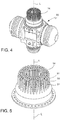
figure 4 shows a Stirling engine, in which a burner was removed to show the heat exchanger, -
figure 5 shows a heat exchanger of a burner-heat exchanger assembly according to an embodiment, -
figure 6 is a diagrammatical depiction of a combustion chamber delimited by a diffuser wall and a heat exchanger, in an angular segment, indicating the fuel mixture flows of the burner, the working fluid of the external combustion engine and the outlet flow of the combustion gases, -
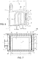
figure 7 is a sectional view according to a radial plane, of a burner-heat exchanger assembly according to the invention, indicating the pertinent geometrical parameters, -
Figures 8 and 9 show graphs of CFD simulations and experimental data concerning the technical effect of the invention. - With reference to the figures, a gas burner-heat exchanger assembly which can be used for external combustion engines, in particular for Stirling engines, is indicated as a whole with
numeral 100.Assembly 100 comprises agas burner 1 and aheat exchanger 14. -
Burner 1 comprises afront wall 2 which defines afront side 3 ofburner 1 and which forms a pass-throughopening 4 for the exchanger, arear wall 5 which defines arear side 6 ofburner 1 and which forms anopening 7 to exhaust combustion gases, and also atubular side wall 8 extending between thefront wall 2 and therear wall 5 and about a longitudinal axis L. -
Burner 1 further comprises atubular diffuser wall 9 arranged inside theside wall 8 and extending between thefront wall 2 and therear wall 5 and about the longitudinal axis L. Thediffuser wall 9 has a perforation for the passage of a gas mixture from anouter side 10 of thediffuser wall 9 to an inner side 11 of thediffuser wall 9 where the combustion takes place. - An
annular distribution chamber 12 is formed between theside wall 8 and thediffuser wall 9 to distribute the gas mixture on theouter side 10 of thediffuser wall 9. Acombustion chamber 13 is formed inside thediffuser wall 9, which chamber is delimited on the rear side by therear wall 5 and is suitable for introducing aheat exchanger 14 from thefront side 3 through the pass-through opening for theexchanger 4 of thefront wall 2. - The
heat exchanger 14 is formed by a tube assembly extending in thecombustion chamber 13 and intended to be passed through by a working fluid, e.g. helium, of the external combustion engine and having aheat exchange surface 31 exposed in thecombustion chamber 13,
in which a minimal diffuser-exchanger distance C, from thediffuser wall 9 to the correspondingheat exchange surface 31, ranges from 20 mm to 40 mm. - Numerical simulations and experimentations have shown that, regardless of the sizing and the thermal input of the burner and regardless of the sizing of the heat exchanger and of the flow speed of the working fluid, in the aforesaid range of minimal diffuser-exchanger distance C between the flame origin (diffuser wall) and the
heat exchange surface 31 closest to the flame origin, there is obtained a favorable reconciliation inside thecombustion chamber 13 between the minimum temperature, the maximum temperature, the thermal gradient which causes the flow of hot combustion gases, the flow speed of the combustion gases and the ability to transfer heat to the heat exchange surfaces, and therefore an increased energy efficiency of the burner-heat exchanger assembly 100 with respect to the solutions of the prior art. - According to one embodiment, the
diffuser wall 9 is substantially cylindrical and coaxial to the longitudinal axis L and theheat exchanger 14 forms a group of radially externalheat exchange surfaces 31 arranged along a circumference about the longitudinal axis L (thus giving the heat exchanger 14 a cylindrical or cylindrical ring outer outline), in which the minimal diffuser-exchanger distance C, measured in a radial direction to the longitudinal axis L, is C = DxAxK/(BxD - 2xAxK) + tolerance,
where: - A is the longitudinal height of the perforated area of the
diffuser wall 9, - B is the longitudinal height of the
heat exchange surfaces 31 inside thecombustion chamber 13, - D is the external diameter of the
heat exchanger 14 inside thecombustion chamber 13, K = 23,6747 is a constant value which has been experimentally determined. - According to the invention, the longitudinal height A of the perforated area of the
diffuser wall 9 is A = 90 mm, the longitudinal height B of theheat exchange surfaces 31 inside thecombustion chamber 13 is B = 90 mm ... 100 mm, and the external diameter D of theheat exchanger 14 inside thecombustion chamber 13 is D = 183 mm. This geometrical configuration is particularly efficient for the sizes and inputs ofexternal combustion engines 32 typically used in the industry (figure 4 ). In this preferred embodiment (underlined values), the minimal diffuser-exchanger distance C which results in a maximum heat exchange efficiency (referred to the choice of distance C, but not necessarily total extremal with reference to all the geometrical, fluid-dynamic and thermodynamic parameters) is C = 31.9 mm. - Without the technical correction coefficient K proposed by the present invention, the internal surface area of the cylindrical diffuser wall of the burner may be estimated by means of the equation Area_burner = A×(D+2×C)×π with (π=greek PI). However, without the technical correction coefficient K, the burner surface systematically is not optimal both with reference to the NOx, CO emissions and with reference to the heat exchange efficiency.
- Precisely to overcome the problem of having to identify technically advantageous solutions by means of tedious experimental tests and numerical solutions for which no recipes or strategies exist which inevitably or convergingly result in an optimized result, the invention proposes to choose the minimum diffuser-heat exchanger distance C between 20 mm and 40 mm, and more particularly to determine the minimum diffuser-heat exchanger distance C by means of the formula indicated above and using the technical correction coefficient K=23,6747.
- The
heat exchanger 14 may comprise a continuous singleheat exchange surface 31, for example, a compact monoblock, corrugated, fretted, finned surface, or a plurality of surfaces, for example outer surfaces of tubes and/or flat parallel surfaces, corrugated, fretted, finned surfaces or other known shapes not herein described in detail. The thermodynamic working fluid may be e.g. air, nitrogen, helium or hydrogen. - In an advantageous but non-limiting embodiment, the
heat exchanger 14 comprises a sequence of straight tube lengths which are parallel to the longitudinal axis L, for example U-shaped tubes and all oriented on planes which are radial to the longitudinal axis L, in which the two legs of the "U" form straight lengths which are parallel to the longitudinal axis L. The U-shaped tubes may form a first tube assembly, radially more external, which alternates with tubes, radially more internal, of a second tube assembly, in which all the tubes of each assembly have the same radial distance from the longitudinal axis L, as shown infigures 4 and 5 . - According to one embodiment, in the
rear wall 5 is formed acooling gap 16 in flow communication with a gas inlet opening 23 and with thedistribution chamber 12 so that the flow of the gas mixture can cool thediffuser wall 9 and also therear wall 5. - In one embodiment shown in the figures, the
rear wall 5 comprises an outer layer 15 (outer metal sheet) having an outerperipheral edge 17 connected with arear edge 18 of theside wall 8, and an inner layer 20 (inner metal sheet) spaced apart from theouter layer 15 and arranged between theouter layer 15 and thecombustion chamber 13 and having an outerperipheral edge 19 connected with arear edge 21 of thediffuser wall 9. Thecooling gap 16 is formed between the outer 15 and inner 20 layers and forms together with the annular distribution chamber 12 a cup-shaped distribution cavity. Due to the configuration of thedistribution 12 andcombustion 13 chambers and to the presence of thecooling gap 16 in therear wall 5, combustion may take place all about theheat exchanger 14. Moreover, undesired thermal dispersions and overheating of the bottom wall and diffuser wall are avoided due to the fact that the flow of gas mixture absorbs the heat in these areas and brings it back into the combustion chamber. - This ensures a quick and efficient heat exchange with reduced thermal dispersions, and protects the rear wall and nearby components from overheating.
- An
exhaust tube 25 is positioned, for example inserted and possibly welded, atcentral openings outer layer 15 and of theinner layer 20, whichtube 25 forms a fume exhaust channel extending through thefume exhaust opening 7 of therear wall 5. Thecooling slot 16 extends with an annular shape about theexhaust tube 25. - The
side wall 8 and thediffuser wall 9 are preferably cylindrical and possibly coaxial. Theside wall 9 advantageously is made of steel and forms the mixture inlet opening 23 which can be connected to a conduit for supplying the fuel gas mixture (not shown in the figures). - As is known, and therefore not shown in the figures, the perforated areas of the
diffuser wall 9 do not necessarily have a perfectly uniform hole shape and distribution. The individual holes may have different shapes and comprise e.g. circular holes, longitudinal longholes or slots, circumferential longholes or slots, and the distance thereof may vary. In particular, the individual holes may be grouped into perforation blocks spaced apart from one another by means of thin strips of wall. - Additionally or alternatively, the perforated steel sheet of the
diffuser wall 9 is covered on the inside with a mesh orfabric layer 28 made of metal, e.g. FeCr alloy, or ceramic or sintered material, which forms the inner surface 11 of thediffuser wall 9 on which the combustion takes place, and moreover performs an insulating function which further increases the thermal resistance ofburner 1. Here, the minimum diffuser-heat exchanger distance C refers to the inner surface of the mesh orfabric layer 28 because, as explained above, C represents the minimum distance between the heat exchange surface and the flame area of origin. - According to one embodiment, the
side wall 8 and thediffuser wall 9 may be connected to thefront 2 and rear 5 walls by means of pressfit and/or welding. - The
front wall 2 is preferably made of steel and may have the shape of an annular disc, preferably circular, with an outer edge which may be used for connecting theburner 1 to the Stirling engine, an intermediate portion to which theside wall 8 and thediffuser wall 9 may be connected and an inner edge which defines theaforesaid opening 4 for the passage of theheat exchanger 14. - According to a further embodiment, a surface of the
inner layer 20 facing thecombustion chamber 13 and possibly also an inner surface of the fume exhaust passage 7 (i.e. of the exhaust tube 25) may be covered by means of a heat-resistant mesh or fabric which is identical or similar to mesh orfabric 28, in order to provide a further mechanical protection and heat barrier. - Indeed, the
first heat exchanger 14 is connected preferably immediately close to or in direct contact with theinner layer 20 in order to avoid any "escape" of exploitable heat toward thefume exhaust 7. However, this may result in a risk of mechanical damage due to the vibrations of theheat exchanger 14, which is subjected to pulsations of the thermodynamic fluid and to the mechanical vibrations of the Stirling engine. - According to a further embodiment, also the metal sheet of the
outer layer 15 is covered by means of a heat-resistant mesh or fabric which is identical or similar to mesh orfabric 28, in order to provide a further thermal protection. - In one embodiment, a
second heat exchanger 30 may be provided, arranged on therear side 6 ofburner 1 and having one or more fluid conduits in heat exchange relation with afume exhaust conduit 29 connected to thefume exhaust opening 7 of therear wall 5. -
Figures 8 and 9 show graphs of CFD simulations and experimental data concerning the technical effect of the invention. The ordinate indicates the energy efficiency of the system, calculated according to the formula shown in the figure. - The T hot and T low and temperature values are values calculated numerically in the simulated domain (in the case of numerical simulation CFD) and measured by thermocouples applied to the heat exchangers in the case of laboratory tests.
- The A parameter takes the
values - The B parameter takes the
values - The C parameter takes the values 20mm, 25mm, 30mm, 35mm in the CFD simulation, and 20mm, 30mm and 40mm in laboratory tests. This variation of the parameter C is achieved by varying the diameter of the burner and leaving the diameter of the heat exchanger constant at D = 183 mm (in the configuration that has been numerically simulated and tested in the laboratory).
- The graphs indicate the maximum efficiency around C = 30 mm.
in which a minimal diffuser-exchanger distance, from the diffuser wall to the corresponding heat exchange surface, ranges from 20 mm to 40 mm.
Claims (8)
- Gas burner-heat exchanger assembly (100) for an external combustion engine (32), in particular for Stirling engines, comprising a gas burner (1) and a heat exchanger (14),
the burner (1) comprising:- a front wall (2) defining a front side (3) of the burner (1) and forming a pass-through opening for the exchanger (4),- a rear wall (5) defining a rear side (6) of the burner (1) and forming an opening (7) to exhaust combustion gases,- a tubular side wall (8) extended between the front wall (2) and the rear wall (5) and about a longitudinal axis (L) of the assembly (100),- a tubular diffuser wall (9) arranged inside the side wall (8) and extended between the front wall (2) and the rear wall (5) and about the longitudinal axis (L), the diffuser wall (9) having a perforation for the passage of a gas mixture from an outer side (10) of the diffuser wall (9) to an inner side (11) of the diffuser wall (9) where the combustion takes place,- an annular distribution chamber (12) formed between the side wall (8) and the diffuser wall (9) to distribute the gas mixture on the outer side (10) of the diffuser wall (9),- a combustion chamber (13) formed inside the diffuser wall (9) and delimited on the rear side by the rear wall (5) and which receives the heat exchanger (14),
wherein the heat exchanger (14) is formed by a tube assembly extended in the combustion chamber (13) and intended to be passed through by a working fluid of the external combustion engine (32) and having a heat exchange surface (31) exposed in the combustion chamber (13),
wherein a minimal diffuser-exchanger distance (C) between the diffuser wall (9) and the corresponding heat exchange surface (31) ranges from 20 mm to 40 mm,
characterized in that a longitudinal height (A) of the perforated area of the diffuser wall (9) is A = 90 mm, a longitudinal height (B) of the heat exchange surfaces (31) inside the combustion chamber (13) is B = 90 mm, and an external diameter (D) of the heat exchanger (14) inside the combustion chamber (13) is D = 183 mm. - Gas burner-heat exchanger assembly (100) according to claim 1, wherein the diffuser wall (9) is substantially cylindrical and coaxial to the longitudinal axis (L) and the heat exchanger (14) forms a group of radially external heat exchange surfaces (31) arranged along a circumference about the longitudinal axis (L), wherein the minimal diffuser-exchanger distance (C), measured in a radial direction with respect to the longitudinal axis (L), is:
 A is the longitudinal height of the perforated area of the diffuser wall (9),B is the longitudinal height of the heat exchange surfaces (31) inside the combustion chamber (13),D is the external diameter of the heat exchanger (14) inside the combustion chamber (13),K = 23,6747,wherein the tolerance is ± 7 mm, preferably ± 3 mm, even more preferably ± 1 mm.
 - Gas burner - heat exchanger assembly (100) according to one of the previous claims, wherein the minimal diffuser-exchanger distance (C) ranges from 29 mm to 35 mm, preferably 32 mm.
- Gas burner - heat exchanger assembly (100) according to one of the previous claims, wherein the heat exchanger (14) comprises a plurality of straight tube lengths parallel with respect to the longitudinal axis (L).
- Gas burner - heat exchanger assembly (100) according to one of the previous claims, wherein the heat exchanger (14) comprises U-shaped tubes, wherein the two legs of the "U" form straight lengths parallel with the longitudinal axis (L).
- Gas burner - heat exchanger assembly (100) according to claim 5, wherein the U-shaped tubes are all oriented in planes radial with respect to the longitudinal axis (L) and form a first tube assembly, radially more external, which alternates with tubes, radially more internal, of a second tube assembly, wherein all the tubes of each assembly have the same radial distance from the longitudinal axis (L).
- Gas burner - heat exchanger assembly (100) according to one of the previous claims, wherein the diffuser wall (9) is internally coated with a mesh or fabric layer (28) forming an internal combustion surface of the diffuser wall (9).
- External combustion engine (32) comprising a gas burner - heat exchanger assembly (100) according to any one of the preceding claims.
Applications Claiming Priority (2)
| Application Number | Priority Date | Filing Date | Title |
|---|---|---|---|
| ITUB2016A000198A ITUB20160198A1 (en) | 2016-01-18 | 2016-01-18 | Burner assembly - heat exchanger for an external combustion engine |
| PCT/IB2016/058070 WO2017125806A1 (en) | 2016-01-18 | 2016-12-29 | Burner-heat exchanger assembly for an external combustion engine |
Publications (2)
| Publication Number | Publication Date |
|---|---|
| EP3405664A1 EP3405664A1 (en) | 2018-11-28 |
| EP3405664B1 true EP3405664B1 (en) | 2020-06-24 |
Family
ID=55860955
Family Applications (1)
| Application Number | Title | Priority Date | Filing Date |
|---|---|---|---|
| EP16834256.6A Active EP3405664B1 (en) | 2016-01-18 | 2016-12-29 | Burner-heat exchanger assembly for an external combustion engine |
Country Status (4)
| Country | Link |
|---|---|
| US (1) | US10619595B2 (en) |
| EP (1) | EP3405664B1 (en) |
| IT (1) | ITUB20160198A1 (en) |
| WO (1) | WO2017125806A1 (en) |
Families Citing this family (1)
| Publication number | Priority date | Publication date | Assignee | Title |
|---|---|---|---|---|
| CN114440459A (en) * | 2020-10-16 | 2022-05-06 | 青岛经济技术开发区海尔热水器有限公司 | Heat exchange system and gas water heater |
Family Cites Families (9)
| Publication number | Priority date | Publication date | Assignee | Title |
|---|---|---|---|---|
| WO1992001196A1 (en) * | 1990-07-06 | 1992-01-23 | Worgas Bruciatori S.R.L. | Methods and apparatus for gas combustion |
| US20020112479A1 (en) * | 2001-01-09 | 2002-08-22 | Keefer Bowie G. | Power plant with energy recovery from fuel storage |
| US6952921B2 (en) * | 2003-10-15 | 2005-10-11 | Stirling Technology Company | Heater head assembly system and method |
| US8387380B2 (en) * | 2006-02-28 | 2013-03-05 | Precision Combustion, Inc. | Catalytic burner apparatus for Stirling Engine |
| DE102008014523A1 (en) * | 2008-03-15 | 2009-09-17 | Robert Bosch Gmbh | heater |
| WO2011157662A1 (en) * | 2010-06-14 | 2011-12-22 | Bekaert Combustion Technology B.V. | Combustion engine with air-cooled bottom gasket |
| ITMI20131480A1 (en) * | 2013-09-09 | 2015-03-10 | Worgas Bruciatori Srl | BURNER WITH ACTIVE INSULATION, IN PARTICULAR FOR AN EXTERNAL COMBUSTION ENGINE |
| EP3006826B1 (en) * | 2014-10-10 | 2017-05-03 | WORGAS BRUCIATORI S.r.l. | Burner |
| IT201600106728A1 (en) * | 2016-10-24 | 2018-04-24 | Worgas Bruciatori Srl | BURNER |
-
2016
- 2016-01-18 IT ITUB2016A000198A patent/ITUB20160198A1/en unknown
- 2016-12-29 EP EP16834256.6A patent/EP3405664B1/en active Active
- 2016-12-29 WO PCT/IB2016/058070 patent/WO2017125806A1/en not_active Ceased
- 2016-12-29 US US16/070,702 patent/US10619595B2/en active Active
Non-Patent Citations (1)
| Title |
|---|
| None * |
Also Published As
| Publication number | Publication date |
|---|---|
| US10619595B2 (en) | 2020-04-14 |
| EP3405664A1 (en) | 2018-11-28 |
| WO2017125806A1 (en) | 2017-07-27 |
| ITUB20160198A1 (en) | 2017-07-18 |
| US20190024607A1 (en) | 2019-01-24 |
Similar Documents
| Publication | Publication Date | Title |
|---|---|---|
| US9423135B2 (en) | Combustor having mixing tube bundle with baffle arrangement for directing fuel | |
| US4329943A (en) | Heating boiler | |
| US7993097B2 (en) | Cooling device for a stationary ring of a gas turbine | |
| US10240475B2 (en) | Heat shields for air seals | |
| US20110185985A1 (en) | Fluid heating apparatus | |
| JP6490199B2 (en) | Acoustic damping system for gas turbine engine combustors. | |
| UA97357C2 (en) | Dual-flow turbomachine | |
| US11619387B2 (en) | Liner for a combustor of a gas turbine engine with metallic corrugated member | |
| RU2012129345A (en) | CAR HEATING DEVICE | |
| EP2657610B1 (en) | A combustor and a method for assembling the combustor | |
| CN109642750A (en) | Heat exchanger for boiler | |
| CN105518385B (en) | Heat power fluid heating unit and its use in gas burner, external-combustion engine | |
| US10619595B2 (en) | Burner-heat exchanger assembly for an external combustion engine | |
| CN105209723A (en) | Heat shield manifold system for a midframe case of a gas turbine engine | |
| CN103196154A (en) | Combustor and method for distributing fuel in the combustor | |
| SE527694C2 (en) | Tubular insert for air preheater tube inside exhaust gas connection for fuel burner, has elastic ring seals in grooves forming seal against inside of tube | |
| CN209637884U (en) | Hot gas transfer shell and gas turbine equipment | |
| Gawande et al. | Design and development of shell & tube heat exchanger for beverage | |
| RU2686357C1 (en) | Gaseous medium heater | |
| JP2019128056A (en) | Cylindrical heat exchanger | |
| EP1684011A1 (en) | Steam generator | |
| CN118111845A (en) | A thermal fatigue simulation part of a flame tube of a reflow combustion chamber and a thermal fatigue test method | |
| JP2026500635A (en) | Radiation shield for gaseous fuel circuits | |
| RU2452863C1 (en) | Gas turbine power plant with heat recovery | |
| RU2188983C2 (en) | Combustion chamber |
Legal Events
| Date | Code | Title | Description |
|---|---|---|---|
| STAA | Information on the status of an ep patent application or granted ep patent |
Free format text: STATUS: UNKNOWN |
|
| STAA | Information on the status of an ep patent application or granted ep patent |
Free format text: STATUS: THE INTERNATIONAL PUBLICATION HAS BEEN MADE |
|
| PUAI | Public reference made under article 153(3) epc to a published international application that has entered the european phase |
Free format text: ORIGINAL CODE: 0009012 |
|
| STAA | Information on the status of an ep patent application or granted ep patent |
Free format text: STATUS: REQUEST FOR EXAMINATION WAS MADE |
|
| 17P | Request for examination filed |
Effective date: 20180608 |
|
| AK | Designated contracting states |
Kind code of ref document: A1 Designated state(s): AL AT BE BG CH CY CZ DE DK EE ES FI FR GB GR HR HU IE IS IT LI LT LU LV MC MK MT NL NO PL PT RO RS SE SI SK SM TR |
|
| AX | Request for extension of the european patent |
Extension state: BA ME |
|
| DAV | Request for validation of the european patent (deleted) | ||
| DAX | Request for extension of the european patent (deleted) | ||
| GRAP | Despatch of communication of intention to grant a patent |
Free format text: ORIGINAL CODE: EPIDOSNIGR1 |
|
| STAA | Information on the status of an ep patent application or granted ep patent |
Free format text: STATUS: GRANT OF PATENT IS INTENDED |
|
| INTG | Intention to grant announced |
Effective date: 20200204 |
|
| TPAC | Observations filed by third parties |
Free format text: ORIGINAL CODE: EPIDOSNTIPA |
|
| GRAS | Grant fee paid |
Free format text: ORIGINAL CODE: EPIDOSNIGR3 |
|
| RAP1 | Party data changed (applicant data changed or rights of an application transferred) |
Owner name: BECKETT THERMAL SOLUTIONS S.R.L. |
|
| GRAA | (expected) grant |
Free format text: ORIGINAL CODE: 0009210 |
|
| STAA | Information on the status of an ep patent application or granted ep patent |
Free format text: STATUS: THE PATENT HAS BEEN GRANTED |
|
| RIN1 | Information on inventor provided before grant (corrected) |
Inventor name: ACOCELLA, ANTONIO |
|
| AK | Designated contracting states |
Kind code of ref document: B1 Designated state(s): AL AT BE BG CH CY CZ DE DK EE ES FI FR GB GR HR HU IE IS IT LI LT LU LV MC MK MT NL NO PL PT RO RS SE SI SK SM TR |
|
| REG | Reference to a national code |
Ref country code: GB Ref legal event code: FG4D |
|
| REG | Reference to a national code |
Ref country code: CH Ref legal event code: EP |
|
| REG | Reference to a national code |
Ref country code: DE Ref legal event code: R096 Ref document number: 602016038869 Country of ref document: DE |
|
| REG | Reference to a national code |
Ref country code: AT Ref legal event code: REF Ref document number: 1284118 Country of ref document: AT Kind code of ref document: T Effective date: 20200715 |
|
| REG | Reference to a national code |
Ref country code: IE Ref legal event code: FG4D |
|
| REG | Reference to a national code |
Ref country code: NL Ref legal event code: FP |
|
| PG25 | Lapsed in a contracting state [announced via postgrant information from national office to epo] |
Ref country code: LT Free format text: LAPSE BECAUSE OF FAILURE TO SUBMIT A TRANSLATION OF THE DESCRIPTION OR TO PAY THE FEE WITHIN THE PRESCRIBED TIME-LIMIT Effective date: 20200624 Ref country code: GR Free format text: LAPSE BECAUSE OF FAILURE TO SUBMIT A TRANSLATION OF THE DESCRIPTION OR TO PAY THE FEE WITHIN THE PRESCRIBED TIME-LIMIT Effective date: 20200925 Ref country code: SE Free format text: LAPSE BECAUSE OF FAILURE TO SUBMIT A TRANSLATION OF THE DESCRIPTION OR TO PAY THE FEE WITHIN THE PRESCRIBED TIME-LIMIT Effective date: 20200624 Ref country code: NO Free format text: LAPSE BECAUSE OF FAILURE TO SUBMIT A TRANSLATION OF THE DESCRIPTION OR TO PAY THE FEE WITHIN THE PRESCRIBED TIME-LIMIT Effective date: 20200924 Ref country code: FI Free format text: LAPSE BECAUSE OF FAILURE TO SUBMIT A TRANSLATION OF THE DESCRIPTION OR TO PAY THE FEE WITHIN THE PRESCRIBED TIME-LIMIT Effective date: 20200624 |
|
| REG | Reference to a national code |
Ref country code: LT Ref legal event code: MG4D |
|
| PG25 | Lapsed in a contracting state [announced via postgrant information from national office to epo] |
Ref country code: RS Free format text: LAPSE BECAUSE OF FAILURE TO SUBMIT A TRANSLATION OF THE DESCRIPTION OR TO PAY THE FEE WITHIN THE PRESCRIBED TIME-LIMIT Effective date: 20200624 Ref country code: HR Free format text: LAPSE BECAUSE OF FAILURE TO SUBMIT A TRANSLATION OF THE DESCRIPTION OR TO PAY THE FEE WITHIN THE PRESCRIBED TIME-LIMIT Effective date: 20200624 Ref country code: BG Free format text: LAPSE BECAUSE OF FAILURE TO SUBMIT A TRANSLATION OF THE DESCRIPTION OR TO PAY THE FEE WITHIN THE PRESCRIBED TIME-LIMIT Effective date: 20200924 Ref country code: LV Free format text: LAPSE BECAUSE OF FAILURE TO SUBMIT A TRANSLATION OF THE DESCRIPTION OR TO PAY THE FEE WITHIN THE PRESCRIBED TIME-LIMIT Effective date: 20200624 |
|
| REG | Reference to a national code |
Ref country code: AT Ref legal event code: MK05 Ref document number: 1284118 Country of ref document: AT Kind code of ref document: T Effective date: 20200624 |
|
| PG25 | Lapsed in a contracting state [announced via postgrant information from national office to epo] |
Ref country code: AL Free format text: LAPSE BECAUSE OF FAILURE TO SUBMIT A TRANSLATION OF THE DESCRIPTION OR TO PAY THE FEE WITHIN THE PRESCRIBED TIME-LIMIT Effective date: 20200624 |
|
| PG25 | Lapsed in a contracting state [announced via postgrant information from national office to epo] |
Ref country code: EE Free format text: LAPSE BECAUSE OF FAILURE TO SUBMIT A TRANSLATION OF THE DESCRIPTION OR TO PAY THE FEE WITHIN THE PRESCRIBED TIME-LIMIT Effective date: 20200624 Ref country code: SM Free format text: LAPSE BECAUSE OF FAILURE TO SUBMIT A TRANSLATION OF THE DESCRIPTION OR TO PAY THE FEE WITHIN THE PRESCRIBED TIME-LIMIT Effective date: 20200624 Ref country code: AT Free format text: LAPSE BECAUSE OF FAILURE TO SUBMIT A TRANSLATION OF THE DESCRIPTION OR TO PAY THE FEE WITHIN THE PRESCRIBED TIME-LIMIT Effective date: 20200624 Ref country code: CZ Free format text: LAPSE BECAUSE OF FAILURE TO SUBMIT A TRANSLATION OF THE DESCRIPTION OR TO PAY THE FEE WITHIN THE PRESCRIBED TIME-LIMIT Effective date: 20200624 Ref country code: ES Free format text: LAPSE BECAUSE OF FAILURE TO SUBMIT A TRANSLATION OF THE DESCRIPTION OR TO PAY THE FEE WITHIN THE PRESCRIBED TIME-LIMIT Effective date: 20200624 Ref country code: PT Free format text: LAPSE BECAUSE OF FAILURE TO SUBMIT A TRANSLATION OF THE DESCRIPTION OR TO PAY THE FEE WITHIN THE PRESCRIBED TIME-LIMIT Effective date: 20201026 Ref country code: IT Free format text: LAPSE BECAUSE OF FAILURE TO SUBMIT A TRANSLATION OF THE DESCRIPTION OR TO PAY THE FEE WITHIN THE PRESCRIBED TIME-LIMIT Effective date: 20200624 |
|
| PG25 | Lapsed in a contracting state [announced via postgrant information from national office to epo] |
Ref country code: PL Free format text: LAPSE BECAUSE OF FAILURE TO SUBMIT A TRANSLATION OF THE DESCRIPTION OR TO PAY THE FEE WITHIN THE PRESCRIBED TIME-LIMIT Effective date: 20200624 Ref country code: SK Free format text: LAPSE BECAUSE OF FAILURE TO SUBMIT A TRANSLATION OF THE DESCRIPTION OR TO PAY THE FEE WITHIN THE PRESCRIBED TIME-LIMIT Effective date: 20200624 Ref country code: IS Free format text: LAPSE BECAUSE OF FAILURE TO SUBMIT A TRANSLATION OF THE DESCRIPTION OR TO PAY THE FEE WITHIN THE PRESCRIBED TIME-LIMIT Effective date: 20201024 |
|
| REG | Reference to a national code |
Ref country code: DE Ref legal event code: R097 Ref document number: 602016038869 Country of ref document: DE |
|
| PG25 | Lapsed in a contracting state [announced via postgrant information from national office to epo] |
Ref country code: DK Free format text: LAPSE BECAUSE OF FAILURE TO SUBMIT A TRANSLATION OF THE DESCRIPTION OR TO PAY THE FEE WITHIN THE PRESCRIBED TIME-LIMIT Effective date: 20200624 |
|
| PLBE | No opposition filed within time limit |
Free format text: ORIGINAL CODE: 0009261 |
|
| STAA | Information on the status of an ep patent application or granted ep patent |
Free format text: STATUS: NO OPPOSITION FILED WITHIN TIME LIMIT |
|
| 26N | No opposition filed |
Effective date: 20210325 |
|
| REG | Reference to a national code |
Ref country code: CH Ref legal event code: PL |
|
| GBPC | Gb: european patent ceased through non-payment of renewal fee |
Effective date: 20201229 |
|
| PG25 | Lapsed in a contracting state [announced via postgrant information from national office to epo] |
Ref country code: SI Free format text: LAPSE BECAUSE OF FAILURE TO SUBMIT A TRANSLATION OF THE DESCRIPTION OR TO PAY THE FEE WITHIN THE PRESCRIBED TIME-LIMIT Effective date: 20200624 Ref country code: MC Free format text: LAPSE BECAUSE OF FAILURE TO SUBMIT A TRANSLATION OF THE DESCRIPTION OR TO PAY THE FEE WITHIN THE PRESCRIBED TIME-LIMIT Effective date: 20200624 |
|
| PG25 | Lapsed in a contracting state [announced via postgrant information from national office to epo] |
Ref country code: IE Free format text: LAPSE BECAUSE OF NON-PAYMENT OF DUE FEES Effective date: 20201229 Ref country code: FR Free format text: LAPSE BECAUSE OF NON-PAYMENT OF DUE FEES Effective date: 20201231 Ref country code: LU Free format text: LAPSE BECAUSE OF NON-PAYMENT OF DUE FEES Effective date: 20201229 |
|
| PG25 | Lapsed in a contracting state [announced via postgrant information from national office to epo] |
Ref country code: CH Free format text: LAPSE BECAUSE OF NON-PAYMENT OF DUE FEES Effective date: 20201231 Ref country code: LI Free format text: LAPSE BECAUSE OF NON-PAYMENT OF DUE FEES Effective date: 20201231 Ref country code: GB Free format text: LAPSE BECAUSE OF NON-PAYMENT OF DUE FEES Effective date: 20201229 |
|
| PG25 | Lapsed in a contracting state [announced via postgrant information from national office to epo] |
Ref country code: IS Free format text: LAPSE BECAUSE OF FAILURE TO SUBMIT A TRANSLATION OF THE DESCRIPTION OR TO PAY THE FEE WITHIN THE PRESCRIBED TIME-LIMIT Effective date: 20201024 Ref country code: TR Free format text: LAPSE BECAUSE OF FAILURE TO SUBMIT A TRANSLATION OF THE DESCRIPTION OR TO PAY THE FEE WITHIN THE PRESCRIBED TIME-LIMIT Effective date: 20200624 Ref country code: MT Free format text: LAPSE BECAUSE OF FAILURE TO SUBMIT A TRANSLATION OF THE DESCRIPTION OR TO PAY THE FEE WITHIN THE PRESCRIBED TIME-LIMIT Effective date: 20200624 Ref country code: CY Free format text: LAPSE BECAUSE OF FAILURE TO SUBMIT A TRANSLATION OF THE DESCRIPTION OR TO PAY THE FEE WITHIN THE PRESCRIBED TIME-LIMIT Effective date: 20200624 |
|
| PG25 | Lapsed in a contracting state [announced via postgrant information from national office to epo] |
Ref country code: MK Free format text: LAPSE BECAUSE OF FAILURE TO SUBMIT A TRANSLATION OF THE DESCRIPTION OR TO PAY THE FEE WITHIN THE PRESCRIBED TIME-LIMIT Effective date: 20200624 |
|
| PGFP | Annual fee paid to national office [announced via postgrant information from national office to epo] |
Ref country code: BE Payment date: 20241218 Year of fee payment: 9 Ref country code: NL Payment date: 20241227 Year of fee payment: 9 |
|
| PGFP | Annual fee paid to national office [announced via postgrant information from national office to epo] |
Ref country code: RO Payment date: 20241217 Year of fee payment: 9 |
|
| PGFP | Annual fee paid to national office [announced via postgrant information from national office to epo] |
Ref country code: DE Payment date: 20241224 Year of fee payment: 9 |