EP3405606B1 - Abrasion resistant textile sleeve, improved multifilament yarn therefor and methods of construction thereof - Google Patents
Abrasion resistant textile sleeve, improved multifilament yarn therefor and methods of construction thereof Download PDFInfo
- Publication number
- EP3405606B1 EP3405606B1 EP17703540.9A EP17703540A EP3405606B1 EP 3405606 B1 EP3405606 B1 EP 3405606B1 EP 17703540 A EP17703540 A EP 17703540A EP 3405606 B1 EP3405606 B1 EP 3405606B1
- Authority
- EP
- European Patent Office
- Prior art keywords
- melt
- low
- multifilaments
- another
- filaments
- Prior art date
- Legal status (The legal status is an assumption and is not a legal conclusion. Google has not performed a legal analysis and makes no representation as to the accuracy of the status listed.)
- Active
Links
Images

Classifications
-
- D—TEXTILES; PAPER
- D03—WEAVING
- D03D—WOVEN FABRICS; METHODS OF WEAVING; LOOMS
- D03D1/00—Woven fabrics designed to make specified articles
- D03D1/0035—Protective fabrics
- D03D1/0041—Cut or abrasion resistant
-
- D—TEXTILES; PAPER
- D03—WEAVING
- D03D—WOVEN FABRICS; METHODS OF WEAVING; LOOMS
- D03D1/00—Woven fabrics designed to make specified articles
- D03D1/0035—Protective fabrics
- D03D1/0043—Protective fabrics for elongated members, i.e. sleeves
-
- D—TEXTILES; PAPER
- D03—WEAVING
- D03D—WOVEN FABRICS; METHODS OF WEAVING; LOOMS
- D03D15/00—Woven fabrics characterised by the material, structure or properties of the fibres, filaments, yarns, threads or other warp or weft elements used
- D03D15/50—Woven fabrics characterised by the material, structure or properties of the fibres, filaments, yarns, threads or other warp or weft elements used characterised by the properties of the yarns or threads
- D03D15/567—Shapes or effects upon shrinkage
-
- D—TEXTILES; PAPER
- D03—WEAVING
- D03D—WOVEN FABRICS; METHODS OF WEAVING; LOOMS
- D03D15/00—Woven fabrics characterised by the material, structure or properties of the fibres, filaments, yarns, threads or other warp or weft elements used
- D03D15/50—Woven fabrics characterised by the material, structure or properties of the fibres, filaments, yarns, threads or other warp or weft elements used characterised by the properties of the yarns or threads
- D03D15/587—Woven fabrics characterised by the material, structure or properties of the fibres, filaments, yarns, threads or other warp or weft elements used characterised by the properties of the yarns or threads adhesive; fusible
-
- D—TEXTILES; PAPER
- D04—BRAIDING; LACE-MAKING; KNITTING; TRIMMINGS; NON-WOVEN FABRICS
- D04C—BRAIDING OR MANUFACTURE OF LACE, INCLUDING BOBBIN-NET OR CARBONISED LACE; BRAIDING MACHINES; BRAID; LACE
- D04C1/00—Braid or lace, e.g. pillow-lace; Processes for the manufacture thereof
- D04C1/02—Braid or lace, e.g. pillow-lace; Processes for the manufacture thereof made from particular materials
-
- D—TEXTILES; PAPER
- D04—BRAIDING; LACE-MAKING; KNITTING; TRIMMINGS; NON-WOVEN FABRICS
- D04C—BRAIDING OR MANUFACTURE OF LACE, INCLUDING BOBBIN-NET OR CARBONISED LACE; BRAIDING MACHINES; BRAID; LACE
- D04C1/00—Braid or lace, e.g. pillow-lace; Processes for the manufacture thereof
- D04C1/06—Braid or lace serving particular purposes
- D04C1/12—Cords, lines, or tows
-
- D—TEXTILES; PAPER
- D06—TREATMENT OF TEXTILES OR THE LIKE; LAUNDERING; FLEXIBLE MATERIALS NOT OTHERWISE PROVIDED FOR
- D06N—WALL, FLOOR, OR LIKE COVERING MATERIALS, e.g. LINOLEUM, OILCLOTH, ARTIFICIAL LEATHER, ROOFING FELT, CONSISTING OF A FIBROUS WEB COATED WITH A LAYER OF MACROMOLECULAR MATERIAL; FLEXIBLE SHEET MATERIAL NOT OTHERWISE PROVIDED FOR
- D06N7/00—Flexible sheet materials not otherwise provided for, e.g. textile threads, filaments, yarns or tow, glued on macromolecular material
-
- G—PHYSICS
- G02—OPTICS
- G02B—OPTICAL ELEMENTS, SYSTEMS OR APPARATUS
- G02B6/00—Light guides; Structural details of arrangements comprising light guides and other optical elements, e.g. couplings
- G02B6/44—Mechanical structures for providing tensile strength and external protection for fibres, e.g. optical transmission cables
- G02B6/4401—Optical cables
- G02B6/4429—Means specially adapted for strengthening or protecting the cables
- G02B6/443—Protective covering
- G02B6/4432—Protective covering with fibre reinforcements
-
- H—ELECTRICITY
- H01—ELECTRIC ELEMENTS
- H01B—CABLES; CONDUCTORS; INSULATORS; SELECTION OF MATERIALS FOR THEIR CONDUCTIVE, INSULATING OR DIELECTRIC PROPERTIES
- H01B17/00—Insulators or insulating bodies characterised by their form
- H01B17/56—Insulating bodies
- H01B17/58—Tubes, sleeves, beads, or bobbins through which the conductor passes
-
- H—ELECTRICITY
- H01—ELECTRIC ELEMENTS
- H01B—CABLES; CONDUCTORS; INSULATORS; SELECTION OF MATERIALS FOR THEIR CONDUCTIVE, INSULATING OR DIELECTRIC PROPERTIES
- H01B7/00—Insulated conductors or cables characterised by their form
- H01B7/17—Protection against damage caused by external factors, e.g. sheaths or armouring
- H01B7/18—Protection against damage caused by wear, mechanical force or pressure; Sheaths; Armouring
-
- H—ELECTRICITY
- H02—GENERATION; CONVERSION OR DISTRIBUTION OF ELECTRIC POWER
- H02G—INSTALLATION OF ELECTRIC CABLES OR LINES, OR OF COMBINED OPTICAL AND ELECTRIC CABLES OR LINES
- H02G3/00—Installations of electric cables or lines or protective tubing therefor in or on buildings, equivalent structures or vehicles
- H02G3/02—Details
- H02G3/04—Protective tubing or conduits, e.g. cable ladders or cable troughs
-
- H—ELECTRICITY
- H02—GENERATION; CONVERSION OR DISTRIBUTION OF ELECTRIC POWER
- H02G—INSTALLATION OF ELECTRIC CABLES OR LINES, OR OF COMBINED OPTICAL AND ELECTRIC CABLES OR LINES
- H02G3/00—Installations of electric cables or lines or protective tubing therefor in or on buildings, equivalent structures or vehicles
- H02G3/02—Details
- H02G3/04—Protective tubing or conduits, e.g. cable ladders or cable troughs
- H02G3/0462—Tubings, i.e. having a closed section
- H02G3/0481—Tubings, i.e. having a closed section with a circular cross-section
-
- D—TEXTILES; PAPER
- D06—TREATMENT OF TEXTILES OR THE LIKE; LAUNDERING; FLEXIBLE MATERIALS NOT OTHERWISE PROVIDED FOR
- D06N—WALL, FLOOR, OR LIKE COVERING MATERIALS, e.g. LINOLEUM, OILCLOTH, ARTIFICIAL LEATHER, ROOFING FELT, CONSISTING OF A FIBROUS WEB COATED WITH A LAYER OF MACROMOLECULAR MATERIAL; FLEXIBLE SHEET MATERIAL NOT OTHERWISE PROVIDED FOR
- D06N2209/00—Properties of the materials
- D06N2209/10—Properties of the materials having mechanical properties
- D06N2209/105—Resistant to abrasion, scratch
-
- D—TEXTILES; PAPER
- D10—INDEXING SCHEME ASSOCIATED WITH SUBLASSES OF SECTION D, RELATING TO TEXTILES
- D10B—INDEXING SCHEME ASSOCIATED WITH SUBLASSES OF SECTION D, RELATING TO TEXTILES
- D10B2401/00—Physical properties
- D10B2401/04—Heat-responsive characteristics
- D10B2401/041—Heat-responsive characteristics thermoplastic; thermosetting
-
- D—TEXTILES; PAPER
- D10—INDEXING SCHEME ASSOCIATED WITH SUBLASSES OF SECTION D, RELATING TO TEXTILES
- D10B—INDEXING SCHEME ASSOCIATED WITH SUBLASSES OF SECTION D, RELATING TO TEXTILES
- D10B2505/00—Industrial
- D10B2505/12—Vehicles
Definitions
- This invention relates generally to textile sleeves for protecting elongate members, and more particularly to abrasion resistant, flexible textile sleeves and to methods of construction thereof.
- an abrasion resistant, flexible textile sleeve for routing and protecting an elongate member contained therein from exposure to abrasion, as recited in the appended claims.
- the sleeve has a wall extending lengthwise along a longitudinal axis between opposite ends, wherein the wall is configured to bound a cavity, in which the elongate member is contained and protected.
- the wall is constructed, at least in part, from improved multifilament yarn, which enhances the abrasion resistance of the sleeve wall, while also allowing the fabric density of the wall to remain relatively low, given the degree of abrasion resistance provided, thereby reducing cost, weight and the outer envelope of the sleeve, while also enhancing the flexibility of the sleeve.
- the improved multifilament yarn includes a plurality of fibers and/or filaments, referred to hereafter for convenience as filaments (being distinguishable by length, with filaments being much longer than fibers, and can extend the entire length of the yarn as continuous, unbroken members, in contrast to much shorter fibers), with at least some of the filaments being provided as “low-melt” filaments and with at least some of the filaments being provided as “standard,” “non-low-melt” filaments.
- “low-melt” it will be recognized by one skilled in the art that the low-melt fibers melt, at least in part, at a lower temperature as compared to the standard melt temperature fibers, if the standard filaments are capable of melting at all.
- the wall is subjected to a predetermined heat treatment process, whereupon the low-melt filaments are caused to melt, at least in part, while the standard melt temperature filaments remain entirely or substantially unmelted.
- the at least partially melted low-melt filaments act as glue to bond all the filaments, including the standard, non-low-melt temperature filaments, of the multifilament yarn to one another.
- the individual filaments are prevented or inhibited from moving in sliding relation relative to one another, which in turn reduces the abrasion between the individual filaments of the multifilament yarn, thus improving the resistance of the sleeve wall to wear from abrasion.
- the melted filaments are bonded to one another, the filaments, and wall formed thereby, remain highly flexible, thereby allowing the resulting sleeve to be routed about meandering paths and corners.
- the elongate members contained therein are optimally protected against external sources of abrasion and contamination.
- the heat-set filaments are integrally provided in the improved multifilament yarns.
- the textile sleeve may be constructed as a woven, knit or braided sleeve.
- the opposite edges are biased into overlapping relation with one another via heat-set, circumferentially extending yarn.
- the improved multifilament yarn includes about 1%-90% low-melt filament content.
- the improved multifilament yarn can have a denier ranging between about 150-20000, as a single or multiply yarn.
- the improved multifilament yarn includes at least one or a plurality heat-settable monofilaments.
- the improved multifilament yarn can include a plurality of low-melt filaments and a plurality of standard melt filaments, wherein the individual filaments can be combed with one another to extending substantially parallel with one another.
- the improved multifilament yarn can include at least one low-melt filament and at least one standard melt filament twisted with one another.
- the improved multifilament yarn can include a plurality of low-melt filaments and a plurality of standard melt filaments braided with one another.
- the improved multifilament yarn can include a plurality of low-melt filaments and a plurality of standard melt filaments air-texturized with one another.
- the improved multifilament yarn can include a plurality of low-melt filaments and a plurality of standard melt filaments twisted and texturized with one another.
- a method of constructing an abrasion resistant textile sleeve for routing and protecting an elongate member contained therein from exposure to abrasion and contamination includes forming a textile wall extending lengthwise along a longitudinal axis between opposite ends at least in part from improved multifilament yarn, formed in accordance with one aspect of the invention.
- the improved multifilament yarn is provided including a plurality of filaments, with at least some of the filaments being provided as "low-melt" filaments and with at least some of the filaments being provided as "standard” melt temperature filaments, if they melt at all.
- the method upon forming the textile wall of the sleeve, includes heat-treating the sleeve and causing the low-melt filaments to melt, at least in part, while avoiding or substantially avoiding melting the standard melt temperature filaments, thereby causing all the filaments within the improved multifilament yarn to be bonded to one another via the at least partially melted low-melt filaments.
- the method further includes heat-setting filaments within said improved multifilament yarns.
- the method of constructing the sleeve includes weaving, knitting or braiding the wall of the sleeve.
- the method of constructing the sleeve includes biasing the opposite edges into overlapping relation with one another via heat-setting circumferentially extending yarn.
- the opposite edges can be biased during the heat-treating process used to melt the low-melt filaments.
- the method of constructing the sleeve includes heat-setting at least one or a plurality of heat-settable yarns contained within the improved multifilament yarn.
- the method of constructing the sleeve can include providing the improved multifilament yarn having a denier ranging between about 150-20000, as a single or multiply yarn.
- the method of constructing the sleeve can include providing the improved multifilament yarn including a plurality of low-melt filaments and a plurality of standard melt filaments, wherein the individual filaments can be combed with one another to extending substantially parallel with one another.
- the method of constructing the sleeve can include providing the improved multifilament yarn including at least one low-melt filament and at least one standard melt filament twisted with one another.
- the method of constructing the sleeve can include providing the improved multifilament yarn including a plurality of low-melt filaments and a plurality of standard melt filaments braided with one another.
- the method of constructing the sleeve can include providing the improved multifilament yarn including a plurality of low-melt filaments and a plurality of standard melt filaments air-texturized and intermingled with one another.
- the method of constructing the sleeve can include providing the improved multifilament yarn including a plurality of low-melt filaments and a plurality of standard melt filaments twisted and texturized with one another.
- the improved multifilament yarn includes providing the low-melt filaments content to be between about 1-90wt%.
- the improved multifilament yarn includes forming the improved multifilament having a denier ranging between about 150-20000, as a single or multiply yarn.
- the improved multifilament yarn includes combining a pre-existing multifilament comprising entirely or substantially standard melt temperature filaments with a pre-existing multifilament comprising entirely or substantially low-melt temperature filaments.
- the pre-existing multifilament of standard melt temperature filaments with the pre-existing multifilament of low-melt temperature filaments can include an intermingling, twisting, texturizing, serving, cabling or similar process.
- the improved multifilament yarn can include combing at least one heat-settable filament with the low-melt filaments and the standard melt filaments.
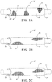
- Figures 1A-1C show schematic representations of textile sleeves, referred to hereafter as sleeve 10, constructed in accordance with various aspects of the invention.
- the sleeve 10 is shown having a wrappable elongate wall 12 for routing and protecting an elongate member 14, such as wires, a wire harness, or tube, for example, from exposure to abrasion and the ingress of contamination, debris and the like.
- an elongate member 14 such as wires, a wire harness, or tube
- the elongate wall 12 has opposite edges 16, 18 extending lengthwise along a longitudinal, central axis 20 between opposite ends 15, 17, wherein the edges 16, 18 are configured to be wrapped into overlapping relation with one another in "cigarette wrapped” fashion to fully enclose the elongate member 14 within a central cavity 22 of the sleeve 10.
- the cavity 22 is readily accessible along the full length of the central axis 20 so that the elongate member 14 can be readily disposed radially into the cavity 22, and conversely, removed from the cavity 22, such as during service.
- the opposite edges 16, 18 can be biased into overlapping relation with one another via heat-set, circumferentially extending yarn, if desired.
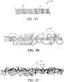
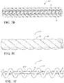
- the wall 12 is constructed, at least in part, with improved multifilament yarn 24 ( Figures 3A-3F show various versions, though it is to be understood the appearance can be different depending on the mechanism used to form the yarn 24, e.g. intermingling, twisting, texturizing, serving, cabling or similar process), via one of a weaving ( Figure 1A ), braiding ( Figure 1B ) or knitting ( Figure 1C ) process.
- the wall 12 can be constructed having any suitable size, including length, width and diameter. If the wall 12 is heat-set and brought into a self-wrapped tubular configuration, generally free from any externally applied forces, the edges 16, 18 preferably overlap one another at least slightly to fully enclose the cavity 22, and thus, provide enhanced protection to the elongate member 14 contained in the cavity 22.
- the lengthwise edges 16, 18 are readily extendable away from one another under an externally applied force sufficient to overcome the bias imparted by the heat-settable monofilaments 30 of polymeric material monofilament, such as polyphenylene sulfide (PPS) or polyethyleneterephthalate (PET), for example, to at least partially open and expose the cavity 22.
- PPS polyphenylene sulfide
- PET polyethyleneterephthalate
- the elongate member 14 can be readily disposed into the cavity 22 during assembly or removed from the cavity 22 during service.
- the edges 16, 18 Upon releasing the externally applied force, the edges 16, 18 return automatically to their overlapping, self-wrapped position under the bias imparted by the heat-set fill monofilament yarns 30.
- the improved multifilament yarn 24 includes a plurality of filaments, with at least some of the filaments being provided as “low-melt” filaments 26 and with at least some of the filaments being provided as “standard” melt temperature filaments 28.
- low-melt it will be recognized by one skilled in the art that the low-melt filaments 26 melt, at least in part, at a lower temperature, such as between about 100-200 °C, by way of example and without limitation, as compared to the standard melt temperature filaments 28, such as between about 260-280 °C, by way of example and without limitation, if at all.
- the sleeve 10 upon forming the textile wall 12 of the sleeve 10, can be heat-treated at a temperature sufficient to at least partially melt the low-melt filaments 26, but low enough to avoid melting the standard filaments 28, whereupon the at least partially melted low-melt filaments 26 act as glue to bond all the filaments, including the standard melt temperature filaments 28, of the improved multifilament 24 to one another.
- the individual filaments 26, 28 are prevented or inhibited from moving relative to one another, which in turn reduces the friction and abrasion between the individual filaments 26, 28 of the improved multifilament 24, thus improving the resistance of the sleeve wall 12 to abrasion, and preventing the individual filaments 26, 28 from being separated and penetrated or otherwise broken by an external abradant source.
- the standard filaments 28 With the standard filaments 28 remaining unmelted, they retain their full tenacity and functionality, thereby further enhancing the protective shielding coverage and abrasion resistance of the wall 12, while minimizing the amount of yarn material needed to provide the desired protection, thus, minimizing the bulk, weight and outer envelope of the sleeve 10.
- low-melt filaments 26 and standard filaments 28 include, respectively; low-melt/polyethylene terephthalate (PET); polypropylene (PP)/PET; low-melt/Nomex®; PP/Nomex®; PET/Nomex®; low-melt/fiberglass; PP/fiberglass; polyethylene (PE)/fiberglass, by way of example and without limitation.
- the low-melt material can be any desired low-melt polymeric material, including a homopolymer, such as polypropylene, polyethylene, etc., or a copolymer, such as copolyester, copolyamide, in the form of a multifilament yarn or mono-component containing or bicomponent containing multifilament yarn.
- Some additional standard filaments 28 may include thermoset fibers, mineral fibers, or metallic yarn, and acrylic fibers, cotton fibers, rayon fibers, and fire retardant (FR) versions of all the aforementioned fiber materials, by way of example and without limitation. It should be recognized that the heat-treating process could be used to heat-set the heat-settable, circumferentially extending yarn of monofilaments 30, if desired, thereby performing multiple functions in a single heat-treating, heat-setting process.
- the improved multifilament yarns 24 were provided as warp yarns in the wrappable sleeve 10 of Figure 1 , having a denier of about 1250.
- the improved multifilament yarns 24 were formed from low-melt multifilament filaments 26 having a denier of about 150 combined with standard multifilament filaments 28 having a denier of about 1100, whereupon combining the two multifilament yarns 26, 28, the resulting improved multifilament yarn 24 has a substantially uniform, homogenous cross-sectional content of the different materials of the two different multifilament yarns 26, 28.
- the sleeve 10 was further constructed having a warp density between about 20-30 end/inch, while the weft density was between about 15-25 picks/inch from monofilaments 30 of about 0.22mm diameter PET, by way of example and without limitation. Then, upon forming the wall 12, the wall 12 was wrapped to bring the opposite edges 16, 18 into overlapping relation with one another and heat-treated in a single heating process, at a suitable temperature, to both heat-set the weft monofilaments 30, thereby maintaining the wall 12 in its wrapped configuration, and also melt the low-melt fibers 26 within the improved multifilament 24, thereby bonding all the filaments 26, 28 of the improved multifilament yarn 24 together via the melted material.
- the weave used to form the wall can be any desired weave pattern, such as a plain weave pattern; however, other weave patterns are contemplated herein, such as twill, basket, satin or sateen, by way of example.
- textile sleeves 10' that are beyond the scope of the invention are shown, wherein the same reference numerals as used above with regard to the sleeve 10, differentiated by a prime symbol ('), are used to identify like features.
- the sleeve 10' is similar to the sleeve 10; however, rather than having an open wall, the wall 12' of the sleeve 10' is circumferentially continuous and seamless, sometimes referred to as a "closed" wall bounding a central cavity 22' that extends between opposite ends 15', 17'.
- the sleeve 10' can be constructed using the same types of construction, i.e.
- any sleeve constructed in accordance with the invention is constructed of a combination of the improved multifilament yarns 24 and at least the aforementioned heat-settable monofilaments 30, and that it further can include other types of yarn, including the aforementioned standard melt temperature multifilaments.
- the improved multifilament yarns 24 can be used in either, or both, warp and weft directions, and as desired in one or both S and Z directions of a braided sleeve construction.
- a method of constructing an improved multifilament yarn 24 includes forming the improved multifilament yarn 24 with a plurality of filaments, with at least some of the filaments being provided as "low-melt” filaments 26 and with at least some of the filaments being provided as "standard” melt temperature filaments 28, if meltable at all, meaning they could be essentially non-meltable, such as the case with mineral type yarns, for example.
- the different types of filaments 26, 28 are separately formed filaments, and thereafter, combined with one another, via one of the various mechanisms disclosed herein, such as shown in Figures 3A-3E , to form the improved multifilament yarn 24.
- the low-melt filaments 26 are provided having a first melt temperature
- the standard melt temperature filaments 28 are provided having a second melt temperature, wherein the first melt temperature is lower than the second melt temperature, such as by about 10-1000 °C, such that upon exposing the improved multifilament yarn 24 to a heat source at a temperature at about the first melt temperature, the low-melt filaments 26 at least partially melt, while the second filaments 28 remain unmelted.
- the low-melt filaments content of the improved multifilament yarn 24 is between about 1-90wt%.
- the improved multifilament yarn 24 is formed having a denier ranging between about 150-20000, as a single or multiply yarn.
- the method of constructing the improved multifilament yarn 24 includes combining a pre-existing multifilament comprising entirely or substantially standard melt temperature filaments 28 with a pre-existing multifilament comprising entirely or substantially low-melt temperature filaments 26.
- the combining process used to combine the low-melt multifilament with the high melt multifilament to form the improved multifilament yarn 24 can include the following, wherein different embodiments of the improved multifilament yarn are identified generally by reference numeral 24, offset by respective prime symbols (', ", "', "", "") to denote different embodiments, though it is to be recognized that any of the embodiments can be used to form a sleeve 10, 10' as discussed above: intermingling/texturizing ( Figures 3A-3C ), braiding ( Figure 3D ), twisting ( Figure 3E ), serving/cabling ( Figure 3F ), or similar processes, by way of example and without limitation.
Landscapes
- Engineering & Computer Science (AREA)
- Textile Engineering (AREA)
- Structural Engineering (AREA)
- Architecture (AREA)
- Civil Engineering (AREA)
- Manufacturing & Machinery (AREA)
- Physics & Mathematics (AREA)
- General Physics & Mathematics (AREA)
- Optics & Photonics (AREA)
- Braiding, Manufacturing Of Bobbin-Net Or Lace, And Manufacturing Of Nets By Knotting (AREA)
- Knitting Of Fabric (AREA)
- Woven Fabrics (AREA)
- Yarns And Mechanical Finishing Of Yarns Or Ropes (AREA)
- Gloves (AREA)
Description
- This invention relates generally to textile sleeves for protecting elongate members, and more particularly to abrasion resistant, flexible textile sleeves and to methods of construction thereof.
- It is known to wrap elongate members in protective sleeves to provide protection to elongate members contained therein against abrasion and contamination. Unfortunately, although known sleeves can be effective at providing such protection to elongate members against abrasion and contamination, they typically have a relative high fabric density, due to the need for increased amounts of yarn material to provide the desired protection against both abrasion and contamination, thereby adding cost, bulk, stiffness and weight to the sleeve. An example of a method for producing fabric having at least one monofilament or monofilament weft thread of highly shrinkable material and warp threads of low-shrinkage material is disclosed in earlier patent application
DE 102007023062 A1 . An example of a woven textile which when heat is applied spontaneously forms into a tube with overlap in the circumferential direction is disclosed in earlier patent applicationEP 2647749 A1 . An example of a woven fiberglass cable wrap for protecting a communications cable is disclosed in earlier patent applicationUS 6003565 A and an example of a tubular cover to house wires in an automobile is disclosed in earlier patent applicationWO 2014/034799 A1 . - According to one aspect of the invention, there is provided an abrasion resistant, flexible textile sleeve for routing and protecting an elongate member contained therein from exposure to abrasion, as recited in the appended claims. The sleeve has a wall extending lengthwise along a longitudinal axis between opposite ends, wherein the wall is configured to bound a cavity, in which the elongate member is contained and protected. The wall is constructed, at least in part, from improved multifilament yarn, which enhances the abrasion resistance of the sleeve wall, while also allowing the fabric density of the wall to remain relatively low, given the degree of abrasion resistance provided, thereby reducing cost, weight and the outer envelope of the sleeve, while also enhancing the flexibility of the sleeve. The improved multifilament yarn includes a plurality of fibers and/or filaments, referred to hereafter for convenience as filaments (being distinguishable by length, with filaments being much longer than fibers, and can extend the entire length of the yarn as continuous, unbroken members, in contrast to much shorter fibers), with at least some of the filaments being provided as "low-melt" filaments and with at least some of the filaments being provided as "standard," "non-low-melt" filaments. By "low-melt" it will be recognized by one skilled in the art that the low-melt fibers melt, at least in part, at a lower temperature as compared to the standard melt temperature fibers, if the standard filaments are capable of melting at all. As such, during production of the sleeve, upon forming the textile, interlaced wall of the sleeve, the wall is subjected to a predetermined heat treatment process, whereupon the low-melt filaments are caused to melt, at least in part, while the standard melt temperature filaments remain entirely or substantially unmelted. The at least partially melted low-melt filaments act as glue to bond all the filaments, including the standard, non-low-melt temperature filaments, of the multifilament yarn to one another. Accordingly, the individual filaments are prevented or inhibited from moving in sliding relation relative to one another, which in turn reduces the abrasion between the individual filaments of the multifilament yarn, thus improving the resistance of the sleeve wall to wear from abrasion. However, although the melted filaments are bonded to one another, the filaments, and wall formed thereby, remain highly flexible, thereby allowing the resulting sleeve to be routed about meandering paths and corners. As such, with the sleeve wall remaining substantially un-abraded in use, the elongate members contained therein are optimally protected against external sources of abrasion and contamination. The heat-set filaments are integrally provided in the improved multifilament yarns.
- In accordance with another aspect of the invention, the textile sleeve may be constructed as a woven, knit or braided sleeve.
- In accordance with the invention, the opposite edges are biased into overlapping relation with one another via heat-set, circumferentially extending yarn.
- In accordance with another aspect of the invention, the improved multifilament yarn includes about 1%-90% low-melt filament content.
- In accordance with another aspect of the invention, the improved multifilament yarn can have a denier ranging between about 150-20000, as a single or multiply yarn.
- In accordance with the invention, the improved multifilament yarn includes at least one or a plurality heat-settable monofilaments.
- In accordance with another aspect of the invention, the improved multifilament yarn can include a plurality of low-melt filaments and a plurality of standard melt filaments, wherein the individual filaments can be combed with one another to extending substantially parallel with one another.
- In accordance with another aspect of the invention, the improved multifilament yarn can include at least one low-melt filament and at least one standard melt filament twisted with one another.
- In accordance with another aspect of the invention, the improved multifilament yarn can include a plurality of low-melt filaments and a plurality of standard melt filaments braided with one another.
- In accordance with another aspect of the invention, the improved multifilament yarn can include a plurality of low-melt filaments and a plurality of standard melt filaments air-texturized with one another.
- In accordance with another aspect of the invention, the improved multifilament yarn can include a plurality of low-melt filaments and a plurality of standard melt filaments twisted and texturized with one another.
- In accordance with another aspect of the invention, there is provided a method of constructing an abrasion resistant textile sleeve for routing and protecting an elongate member contained therein from exposure to abrasion and contamination, as recited in the appended claims. The method includes forming a textile wall extending lengthwise along a longitudinal axis between opposite ends at least in part from improved multifilament yarn, formed in accordance with one aspect of the invention. The improved multifilament yarn is provided including a plurality of filaments, with at least some of the filaments being provided as "low-melt" filaments and with at least some of the filaments being provided as "standard" melt temperature filaments, if they melt at all. Then, upon forming the textile wall of the sleeve, the method includes heat-treating the sleeve and causing the low-melt filaments to melt, at least in part, while avoiding or substantially avoiding melting the standard melt temperature filaments, thereby causing all the filaments within the improved multifilament yarn to be bonded to one another via the at least partially melted low-melt filaments. The method further includes heat-setting filaments within said improved multifilament yarns.
- In accordance with another aspect of the invention, the method of constructing the sleeve includes weaving, knitting or braiding the wall of the sleeve.
- In accordance with the invention, the method of constructing the sleeve includes biasing the opposite edges into overlapping relation with one another via heat-setting circumferentially extending yarn. The opposite edges can be biased during the heat-treating process used to melt the low-melt filaments.
- In accordance with the invention, the method of constructing the sleeve includes heat-setting at least one or a plurality of heat-settable yarns contained within the improved multifilament yarn.
- In accordance with another aspect of the invention, the method of constructing the sleeve can include providing the improved multifilament yarn having a denier ranging between about 150-20000, as a single or multiply yarn.
- In accordance with another aspect of the invention, the method of constructing the sleeve can include providing the improved multifilament yarn including a plurality of low-melt filaments and a plurality of standard melt filaments, wherein the individual filaments can be combed with one another to extending substantially parallel with one another.
- In accordance with another aspect of the invention, the method of constructing the sleeve can include providing the improved multifilament yarn including at least one low-melt filament and at least one standard melt filament twisted with one another.
- In accordance with another aspect of the invention, the method of constructing the sleeve can include providing the improved multifilament yarn including a plurality of low-melt filaments and a plurality of standard melt filaments braided with one another.
- In accordance with another aspect of the invention, the method of constructing the sleeve can include providing the improved multifilament yarn including a plurality of low-melt filaments and a plurality of standard melt filaments air-texturized and intermingled with one another.
- In accordance with another aspect of the invention, the method of constructing the sleeve can include providing the improved multifilament yarn including a plurality of low-melt filaments and a plurality of standard melt filaments twisted and texturized with one another.
- In accordance with another aspect of the invention, the improved multifilament yarn includes providing the low-melt filaments content to be between about 1-90wt%.
- In accordance with another aspect of the invention, the improved multifilament yarn includes forming the improved multifilament having a denier ranging between about 150-20000, as a single or multiply yarn.
- In accordance with another aspect of the invention, the improved multifilament yarn includes combining a pre-existing multifilament comprising entirely or substantially standard melt temperature filaments with a pre-existing multifilament comprising entirely or substantially low-melt temperature filaments.
- In accordance with another aspect of the invention, the pre-existing multifilament of standard melt temperature filaments with the pre-existing multifilament of low-melt temperature filaments can include an intermingling, twisting, texturizing, serving, cabling or similar process.
- In accordance with another aspect of the invention, the improved multifilament yarn can include combing at least one heat-settable filament with the low-melt filaments and the standard melt filaments.
- These and other aspects, features and advantages will become readily apparent to those skilled in the art in view of the following detailed description of presently preferred embodiments and best mode, appended claims, and accompanying drawings, in which:
-
Figures 1A-1C are schematic perspective views of textile sleeves constructed in accordance with various aspects of the invention shown carrying and protecting an elongate member therein; -
Figures 2A-2C are schematic perspective views of textile sleeves shown carrying and protecting an elongate member therein; and -
Figures 3A-3F are an enlarged partial schematic views of improved multifilament yarns used, at least in part, to construct the sleeves ofFigures 1A-1C and2A-2C . - Referring in more detail to the drawings,
Figures 1A-1C show schematic representations of textile sleeves, referred to hereafter assleeve 10, constructed in accordance with various aspects of the invention. Thesleeve 10 is shown having a wrappableelongate wall 12 for routing and protecting anelongate member 14, such as wires, a wire harness, or tube, for example, from exposure to abrasion and the ingress of contamination, debris and the like. Theelongate wall 12 hasopposite edges 16, 18 extending lengthwise along a longitudinal,central axis 20 betweenopposite ends edges 16, 18 are configured to be wrapped into overlapping relation with one another in "cigarette wrapped" fashion to fully enclose theelongate member 14 within acentral cavity 22 of thesleeve 10. Thecavity 22 is readily accessible along the full length of thecentral axis 20 so that theelongate member 14 can be readily disposed radially into thecavity 22, and conversely, removed from thecavity 22, such as during service. Theopposite edges 16, 18 can be biased into overlapping relation with one another via heat-set, circumferentially extending yarn, if desired. To provide protection to theelongate member 14 against abrasion and contamination, and to enhance the ability of thewall 12 to resist being abraded, thewall 12 is constructed, at least in part, with improved multifilament yarn 24 (Figures 3A-3F show various versions, though it is to be understood the appearance can be different depending on the mechanism used to form theyarn 24, e.g. intermingling, twisting, texturizing, serving, cabling or similar process), via one of a weaving (Figure 1A ), braiding (Figure 1B ) or knitting (Figure 1C ) process. - Depending on the application needs, the
wall 12 can be constructed having any suitable size, including length, width and diameter. If thewall 12 is heat-set and brought into a self-wrapped tubular configuration, generally free from any externally applied forces, theedges 16, 18 preferably overlap one another at least slightly to fully enclose thecavity 22, and thus, provide enhanced protection to theelongate member 14 contained in thecavity 22. The lengthwise edges 16, 18 are readily extendable away from one another under an externally applied force sufficient to overcome the bias imparted by the heat-settable monofilaments 30 of polymeric material monofilament, such as polyphenylene sulfide (PPS) or polyethyleneterephthalate (PET), for example, to at least partially open and expose thecavity 22. Accordingly, theelongate member 14 can be readily disposed into thecavity 22 during assembly or removed from thecavity 22 during service. Upon releasing the externally applied force, theedges 16, 18 return automatically to their overlapping, self-wrapped position under the bias imparted by the heat-setfill monofilament yarns 30. - The improved
multifilament yarn 24 includes a plurality of filaments, with at least some of the filaments being provided as "low-melt"filaments 26 and with at least some of the filaments being provided as "standard"melt temperature filaments 28. By "low-melt" it will be recognized by one skilled in the art that the low-melt filaments 26 melt, at least in part, at a lower temperature, such as between about 100-200 °C, by way of example and without limitation, as compared to the standardmelt temperature filaments 28, such as between about 260-280 °C, by way of example and without limitation, if at all. As such, upon forming thetextile wall 12 of thesleeve 10, thesleeve 10 can be heat-treated at a temperature sufficient to at least partially melt the low-melt filaments 26, but low enough to avoid melting thestandard filaments 28, whereupon the at least partially melted low-melt filaments 26 act as glue to bond all the filaments, including the standardmelt temperature filaments 28, of the improved multifilament 24 to one another. Accordingly, theindividual filaments individual filaments improved multifilament 24, thus improving the resistance of thesleeve wall 12 to abrasion, and preventing theindividual filaments standard filaments 28 remaining unmelted, they retain their full tenacity and functionality, thereby further enhancing the protective shielding coverage and abrasion resistance of thewall 12, while minimizing the amount of yarn material needed to provide the desired protection, thus, minimizing the bulk, weight and outer envelope of thesleeve 10. Some non-limiting examples of types of low-melt filaments 26 andstandard filaments 28 include, respectively; low-melt/polyethylene terephthalate (PET); polypropylene (PP)/PET; low-melt/Nomex®; PP/Nomex®; PET/Nomex®; low-melt/fiberglass; PP/fiberglass; polyethylene (PE)/fiberglass, by way of example and without limitation. The low-melt material can be any desired low-melt polymeric material, including a homopolymer, such as polypropylene, polyethylene, etc., or a copolymer, such as copolyester, copolyamide, in the form of a multifilament yarn or mono-component containing or bicomponent containing multifilament yarn. Some additionalstandard filaments 28 may include thermoset fibers, mineral fibers, or metallic yarn, and acrylic fibers, cotton fibers, rayon fibers, and fire retardant (FR) versions of all the aforementioned fiber materials, by way of example and without limitation. It should be recognized that the heat-treating process could be used to heat-set the heat-settable, circumferentially extending yarn ofmonofilaments 30, if desired, thereby performing multiple functions in a single heat-treating, heat-setting process. - In one exemplary sleeve embodiment, the improved
multifilament yarns 24 were provided as warp yarns in thewrappable sleeve 10 ofFigure 1 , having a denier of about 1250. The improvedmultifilament yarns 24 were formed from low-meltmultifilament filaments 26 having a denier of about 150 combined with standardmultifilament filaments 28 having a denier of about 1100, whereupon combining the twomultifilament yarns multifilament yarn 24 has a substantially uniform, homogenous cross-sectional content of the different materials of the two differentmultifilament yarns sleeve 10 was further constructed having a warp density between about 20-30 end/inch, while the weft density was between about 15-25 picks/inch frommonofilaments 30 of about 0.22mm diameter PET, by way of example and without limitation. Then, upon forming thewall 12, thewall 12 was wrapped to bring theopposite edges 16, 18 into overlapping relation with one another and heat-treated in a single heating process, at a suitable temperature, to both heat-set theweft monofilaments 30, thereby maintaining thewall 12 in its wrapped configuration, and also melt the low-melt fibers 26 within the improved multifilament 24, thereby bonding all thefilaments multifilament yarn 24 together via the melted material. The weave used to form the wall can be any desired weave pattern, such as a plain weave pattern; however, other weave patterns are contemplated herein, such as twill, basket, satin or sateen, by way of example. - In
Figures 2A-2C , textile sleeves 10' that are beyond the scope of the invention are shown, wherein the same reference numerals as used above with regard to thesleeve 10, differentiated by a prime symbol ('), are used to identify like features. The sleeve 10' is similar to thesleeve 10; however, rather than having an open wall, the wall 12' of the sleeve 10' is circumferentially continuous and seamless, sometimes referred to as a "closed" wall bounding a central cavity 22' that extends between opposite ends 15', 17'. The sleeve 10' can be constructed using the same types of construction, i.e. weaving (Figure 2A ), braiding (Figure 2B ), knitting (Figure 2C ), as discussed above for thesleeve 10, and including the improved multifilaments 24 and optionally other yarns, as discussed above, such as the standard melt temperature multifilaments and/or monofilaments of any material type, as desired. It should be recognized that any sleeve constructed in accordance with the invention is constructed of a combination of the improvedmultifilament yarns 24 and at least the aforementioned heat-settable monofilaments 30, and that it further can include other types of yarn, including the aforementioned standard melt temperature multifilaments. It should further be understood that the improvedmultifilament yarns 24 can be used in either, or both, warp and weft directions, and as desired in one or both S and Z directions of a braided sleeve construction. - In accordance with another aspect of the invention, a method of constructing an improved
multifilament yarn 24 is provided. The method includes forming the improvedmultifilament yarn 24 with a plurality of filaments, with at least some of the filaments being provided as "low-melt"filaments 26 and with at least some of the filaments being provided as "standard"melt temperature filaments 28, if meltable at all, meaning they could be essentially non-meltable, such as the case with mineral type yarns, for example. It should be recognized that the different types offilaments Figures 3A-3E , to form the improvedmultifilament yarn 24. The low-melt filaments 26 are provided having a first melt temperature, and the standardmelt temperature filaments 28 are provided having a second melt temperature, wherein the first melt temperature is lower than the second melt temperature, such as by about 10-1000 °C, such that upon exposing the improvedmultifilament yarn 24 to a heat source at a temperature at about the first melt temperature, the low-melt filaments 26 at least partially melt, while thesecond filaments 28 remain unmelted. The low-melt filaments content of the improvedmultifilament yarn 24 is between about 1-90wt%. The improvedmultifilament yarn 24 is formed having a denier ranging between about 150-20000, as a single or multiply yarn. The method of constructing the improvedmultifilament yarn 24 includes combining a pre-existing multifilament comprising entirely or substantially standardmelt temperature filaments 28 with a pre-existing multifilament comprising entirely or substantially low-melt temperature filaments 26. The combining process used to combine the low-melt multifilament with the high melt multifilament to form the improvedmultifilament yarn 24 can include the following, wherein different embodiments of the improved multifilament yarn are identified generally byreference numeral 24, offset by respective prime symbols (', ", "', "", "") to denote different embodiments, though it is to be recognized that any of the embodiments can be used to form asleeve 10, 10' as discussed above: intermingling/texturizing (Figures 3A-3C ), braiding (Figure 3D ), twisting (Figure 3E ), serving/cabling (Figure 3F ), or similar processes, by way of example and without limitation. - Many modifications and variations of the present invention are possible in light of the above teachings. It is, therefore, to be understood that the invention may be practiced otherwise than as specifically described, and that the scope of the invention is defined by claims allowed.
Claims (12)
- A textile sleeve (10) for routing and protecting an elongate member (14) against abrasion, comprising:a flexible wall (12) having a plurality of yarns interlaced with one another, at least some of said plurality of yarns being improved multifilament yarns (24"'") including low-melt multifilaments (26) and non-low-melt multifilaments (28), said low-melt multifilaments having a first melt temperature and said non-low-melt multifilaments having a second melt temperature, said second melt temperature being greater than said first melt temperature, said low-melt multifilaments being bonded with said non-low-melt multifilaments to prevent relative sliding movement between said low-melt multifilaments and said non-low-melt multifilaments,wherein said wall has opposite edges (16, 18) extending generally parallel to a central axis (20) between opposite ends (15, 17), with the opposite edges being brought into overlapping relation with one another and said sleeve further including circumferentially extending, heat-set monofilaments (30) biasing said opposite edges into overlapping relation with one another, said heat-set filaments being integrally provided in said improved multifilament yarns (24"'").
- The textile sleeve (10) of claim 1, wherein said low-melt multifilaments (26) and said non-low-melt multifilaments (28) within each of said improved multifilament yarns (24"'") are twisted with one another.
- The textile sleeve (10) of claim 1, wherein said low-melt multifilaments (26) and said non-low-melt multifilaments (28) within each of said improved multifilament yarns (24"'") are combed together to extend generally parallel with one another.
- The textile sleeve (10) of claim 1, wherein said low-melt multifilaments (26) and said non-low-melt multifilaments (28) within each of said improved multifilament yarns (24"'") are intertwined with one another.
- The textile sleeve (10) of claim 1, wherein said low-melt multifilaments (26) and said non-low-melt multifilaments (28) within each of said improved multifilament yarns (24"'") are braided with one another.
- The textile sleeve (10) of claim 1, wherein at least some of said low-melt multifilaments (26) and at least some of said non-low-melt multifilaments (28) within each of said improved multifilament yarns (24"'") are twisted and served with one another.
- A method of constructing a textile sleeve (10) for routing and protecting an elongate member (14) against abrasion, comprising:forming a wall (12) having opposite edges (16, 18) extending generally parallel to a central axis (20) between opposite ends (15, 17) by interlacing a plurality of yarns interlaced with one another and providing at least some of said plurality of yarns being improved multifilament yarns (24"'") including low-melt multifilaments (26) and non-low-melt multifilaments (28), said low-melt multifilaments having a first melt temperature and said non-low-melt multifilaments having a second melt temperature, said second melt temperature being greater than said first melt temperature;bonding said low-melt multifilaments with said non-low-melt multifilaments via a heat-treatment process to prevent relative sliding movement between said low-melt multifilaments and said non-low-melt multifilaments; andbringing the opposite edges into overlapping relation with one another to bound a central cavity (22) by including heat-setting monofilaments (30) within the wall to bias said opposite edges into overlapping relation with one anotherfurther including incorporating the monofilaments (30) within said improved multifilament yarns.
- The method of claim 7, further including providing the low-melt multifilaments (26) and the non-low-melt multifilaments (28) within each of the improved multifilament yarns as being twisted (24"'") with one another.
- The method of claim 7, further including providing the low-melt multifilaments (26) and the non-low-melt multifilaments (28) within each of said improved multifilament yarns (24"'") as being combed together in generally parallel relation with one another.
- The method of claim 7, further including providing the low-melt multifilaments (26) and the non-low-melt multifilaments (28) within each of said improved multifilament yarns (24"'") as being intertwined with one another.
- The method of claim 7, further including providing the low-melt multifilaments (26) and the non-low-melt multifilaments (28) within each of said improved multifilament yarns as being braided (24"'") with one another.
- The method of claim 7, further including providing at least some of the low-melt multifilaments (26) and at least some of the non-low-melt multifilaments (28) within each of said improved multifilament yarns (24"'") as being twisted and served with one another.
Applications Claiming Priority (3)
| Application Number | Priority Date | Filing Date | Title |
|---|---|---|---|
| US201662280923P | 2016-01-20 | 2016-01-20 | |
| US15/409,150 US12051527B2 (en) | 2016-01-20 | 2017-01-18 | Abrasion resistant textile sleeve, improved multifilament yarn therefor and methods of construction thereof |
| PCT/US2017/014041 WO2017127488A1 (en) | 2016-01-20 | 2017-01-19 | Abrasion resistant textile sleeve, improved multifilament yarn therefor and methods of construction thereof |
Publications (2)
| Publication Number | Publication Date |
|---|---|
| EP3405606A1 EP3405606A1 (en) | 2018-11-28 |
| EP3405606B1 true EP3405606B1 (en) | 2021-11-10 |
Family
ID=59314932
Family Applications (1)
| Application Number | Title | Priority Date | Filing Date |
|---|---|---|---|
| EP17703540.9A Active EP3405606B1 (en) | 2016-01-20 | 2017-01-19 | Abrasion resistant textile sleeve, improved multifilament yarn therefor and methods of construction thereof |
Country Status (7)
| Country | Link |
|---|---|
| US (1) | US12051527B2 (en) |
| EP (1) | EP3405606B1 (en) |
| JP (1) | JP7043408B2 (en) |
| KR (1) | KR102586533B1 (en) |
| CN (1) | CN108463585B (en) |
| BR (1) | BR112018014766A2 (en) |
| WO (1) | WO2017127488A1 (en) |
Families Citing this family (7)
| Publication number | Priority date | Publication date | Assignee | Title |
|---|---|---|---|---|
| US10202714B2 (en) * | 2014-10-30 | 2019-02-12 | Federal-Mogul Powertrain Llc | Braided textile sleeve with self-sustaining expanded and contracted states and method of construction thereof |
| US10519578B2 (en) * | 2015-10-29 | 2019-12-31 | Federal-Mogul Powertrain Llc | Self-wrapping, braided textile sleeve with self-sustaining expanded and contracted states and method of construction thereof |
| US10443166B2 (en) * | 2015-10-30 | 2019-10-15 | Federal-Mogul Powertrain Llc | Braided textile sleeve with integrated opening and self-sustaining expanded and contracted states and method of construction thereof |
| US10615581B2 (en) * | 2017-04-04 | 2020-04-07 | Federal-Mogul Powertrain, Llc | Woven EMI and abrasion resistant sleeve and method of construction thereof |
| US11370179B2 (en) * | 2017-07-28 | 2022-06-28 | Federal-Mogul Powertrain Llc | Braided textile sleeve with hot-melt adhesive yarn and method of construction thereof |
| US11434590B2 (en) * | 2017-07-28 | 2022-09-06 | Federal-Mogul Powertrain Llc | Braided textile sleeve with locked yarns and method of construction thereof |
| US11522347B2 (en) * | 2018-06-12 | 2022-12-06 | Wesco Distribution, Inc. | Method of making an innerduct for a conduit |
Citations (1)
| Publication number | Priority date | Publication date | Assignee | Title |
|---|---|---|---|---|
| WO2016010730A1 (en) * | 2014-07-16 | 2016-01-21 | Federal-Mogul Powertrain, Inc. | Protective sleeve with bonded wire filaments and methods of construction thereof |
Family Cites Families (22)
| Publication number | Priority date | Publication date | Assignee | Title |
|---|---|---|---|---|
| US2777310A (en) * | 1955-10-31 | 1957-01-15 | Alamance Ind Inc | Stretch yarn and fabric and method of making same |
| US2890567A (en) * | 1956-05-24 | 1959-06-16 | Burlington Industries Inc | Combination yarn |
| FR2446336A1 (en) * | 1979-01-10 | 1980-08-08 | Payen & Cie L | NOVEL TYPE OF GUIP TEXTILE YARN AND METHOD FOR OBTAINING SAME |
| US6003565A (en) * | 1998-02-26 | 1999-12-21 | Bgf Industries, Inc. | Woven fiberglass cable wrap |
| JP4428655B2 (en) | 2002-06-20 | 2010-03-10 | フェデラル−モーグル パワートレイン インコーポレイテッド | Multi-layer insulation sleeve |
| BRPI0313874B1 (en) * | 2002-08-28 | 2016-03-15 | Federal Mogul Powertrain Inc | elongated sleeve structure, mounting to receive elongated items, and method for positioning and securing elongated items within a duct |
| US20050124249A1 (en) | 2003-12-09 | 2005-06-09 | Uribarri Peter V. | Abrasion-resistant sleeve for wiring and the like |
| US8118967B2 (en) | 2008-01-17 | 2012-02-21 | Seamless Technologies, Llc | Methods of manufacturing paint roller covers from a tubular fabric sleeve |
| US8182645B2 (en) | 2008-01-17 | 2012-05-22 | Seamless Technologies, Llc | Methods of manufacturing paint roller covers from a tubular fabric sleeve |
| US8298364B2 (en) | 2008-01-17 | 2012-10-30 | Seamless Technologies, Llc | Methods of manufacturing paint roller covers from a tubular fabric sleeve |
| DE102007023062A1 (en) | 2007-05-16 | 2008-11-20 | Iprotex Gmbh & Co. Kg | Method for producing a fabric and tissue produced thereby |
| US8701716B2 (en) | 2008-02-29 | 2014-04-22 | Federal-Mogul Corporation | Protective textile sleeve having high edge abrasion resistance and method of construction |
| CN101722599B (en) | 2009-11-11 | 2012-02-22 | 孙金军 | Mold rotation stripping mechanism |
| GB2477531B (en) * | 2010-02-05 | 2015-02-18 | Univ Leeds | Carbon fibre yarn and method for the production thereof |
| EP2647749A4 (en) | 2010-11-29 | 2014-04-30 | Toray Industries | Fabric and covering material for electrical wiring using same |
| JP6014839B2 (en) | 2012-08-30 | 2016-10-26 | 豊通マテックス株式会社 | Tubular cover and automobile using tubular cover for wire storage |
| US8875746B2 (en) * | 2012-10-02 | 2014-11-04 | Federal-Mogul Powertrain, Inc. | Textile sleeve with twisted hybrid fill yarn and method of construction thereof |
| US9394636B2 (en) * | 2013-02-06 | 2016-07-19 | Federal-Mogul Powertrain, Inc. | Enhanced braided sleeve and method of construction thereof |
| US10132012B2 (en) | 2013-03-14 | 2018-11-20 | Federal-Mogul Powertrain Llc | End-fray resistant heat-shrinkable woven sleeve, assembly therewith and methods of construction thereof |
| WO2014140207A1 (en) | 2013-03-15 | 2014-09-18 | Delfingen Fr-Anteuil | Elongate self-closing sleeve for protecting elongate members |
| US9307685B2 (en) * | 2014-07-16 | 2016-04-05 | Federal-Mogul Powertrain, Inc. | Protective sleeve with bonded wire filaments and methods of construction thereof |
| JP6653093B2 (en) | 2014-10-31 | 2020-02-26 | 株式会社 加島 | Protection sleeve and method of manufacturing the same |
-
2017
- 2017-01-18 US US15/409,150 patent/US12051527B2/en active Active
- 2017-01-19 WO PCT/US2017/014041 patent/WO2017127488A1/en not_active Ceased
- 2017-01-19 EP EP17703540.9A patent/EP3405606B1/en active Active
- 2017-01-19 JP JP2018537836A patent/JP7043408B2/en active Active
- 2017-01-19 CN CN201780006861.2A patent/CN108463585B/en active Active
- 2017-01-19 KR KR1020187023686A patent/KR102586533B1/en active Active
- 2017-01-19 BR BR112018014766A patent/BR112018014766A2/en not_active IP Right Cessation
Patent Citations (1)
| Publication number | Priority date | Publication date | Assignee | Title |
|---|---|---|---|---|
| WO2016010730A1 (en) * | 2014-07-16 | 2016-01-21 | Federal-Mogul Powertrain, Inc. | Protective sleeve with bonded wire filaments and methods of construction thereof |
Also Published As
| Publication number | Publication date |
|---|---|
| US20170207005A1 (en) | 2017-07-20 |
| CN108463585B (en) | 2022-01-11 |
| JP7043408B2 (en) | 2022-03-29 |
| BR112018014766A2 (en) | 2018-12-11 |
| EP3405606A1 (en) | 2018-11-28 |
| CN108463585A (en) | 2018-08-28 |
| KR102586533B1 (en) | 2023-10-11 |
| US12051527B2 (en) | 2024-07-30 |
| KR20180101556A (en) | 2018-09-12 |
| JP2019506541A (en) | 2019-03-07 |
| WO2017127488A1 (en) | 2017-07-27 |
| WO2017127488A8 (en) | 2018-09-13 |
Similar Documents
| Publication | Publication Date | Title |
|---|---|---|
| US12051527B2 (en) | Abrasion resistant textile sleeve, improved multifilament yarn therefor and methods of construction thereof | |
| US10675832B2 (en) | Transparent, end-fray and EMI resistant textile sleeve and method of construction thereof | |
| JP6716660B2 (en) | Improved braided sleeve and method of making the same | |
| US11313059B2 (en) | Self-wrapping, braided textile sleeve with self-sustaining expanded and contracted states and method of construction thereof | |
| CN107109730B (en) | Braided textile sleeve with self-retaining extended and contracted states and method of construction thereof | |
| JP6441887B2 (en) | EMI shielding textile fabric, wrappable sleeve constructed therefrom and method of construction thereof | |
| KR102105732B1 (en) | Textile sleeve with twisted hybrid fill yarn and method of construction thereof | |
| US10357933B2 (en) | Woven tubular thermal sleeve and method of construction thereof | |
| CN101390264A (en) | Self-crimping braided sleeve and method of manufacture | |
| JP2017524078A (en) | Protective sleeve with bonded wire filaments and method of construction | |
| JP6662639B2 (en) | Improved braided sleeve and method of making the same | |
| RU2710530C2 (en) | Woven textile sleeve with integrated hole and self-supported expanded and compressed states and method for production thereof | |
| JP2019506541A5 (en) | ||
| CN102334256A (en) | Protective tube and related manufacturing method | |
| CN113710839A (en) | Flexible abrasion resistant braided sleeve and method of construction thereof |
Legal Events
| Date | Code | Title | Description |
|---|---|---|---|
| STAA | Information on the status of an ep patent application or granted ep patent |
Free format text: STATUS: UNKNOWN |
|
| STAA | Information on the status of an ep patent application or granted ep patent |
Free format text: STATUS: THE INTERNATIONAL PUBLICATION HAS BEEN MADE |
|
| PUAI | Public reference made under article 153(3) epc to a published international application that has entered the european phase |
Free format text: ORIGINAL CODE: 0009012 |
|
| STAA | Information on the status of an ep patent application or granted ep patent |
Free format text: STATUS: REQUEST FOR EXAMINATION WAS MADE |
|
| 17P | Request for examination filed |
Effective date: 20180725 |
|
| AK | Designated contracting states |
Kind code of ref document: A1 Designated state(s): AL AT BE BG CH CY CZ DE DK EE ES FI FR GB GR HR HU IE IS IT LI LT LU LV MC MK MT NL NO PL PT RO RS SE SI SK SM TR |
|
| AX | Request for extension of the european patent |
Extension state: BA ME |
|
| DAV | Request for validation of the european patent (deleted) | ||
| DAX | Request for extension of the european patent (deleted) | ||
| STAA | Information on the status of an ep patent application or granted ep patent |
Free format text: STATUS: EXAMINATION IS IN PROGRESS |
|
| 17Q | First examination report despatched |
Effective date: 20200513 |
|
| REG | Reference to a national code |
Ref country code: DE Ref legal event code: R079 Ref document number: 602017049051 Country of ref document: DE Free format text: PREVIOUS MAIN CLASS: D03D0001000000 Ipc: D03D0015567000 |
|
| RIC1 | Information provided on ipc code assigned before grant |
Ipc: D03D 15/567 20210101AFI20210615BHEP Ipc: D03D 15/587 20210101ALI20210615BHEP |
|
| GRAP | Despatch of communication of intention to grant a patent |
Free format text: ORIGINAL CODE: EPIDOSNIGR1 |
|
| STAA | Information on the status of an ep patent application or granted ep patent |
Free format text: STATUS: GRANT OF PATENT IS INTENDED |
|
| INTG | Intention to grant announced |
Effective date: 20210730 |
|
| GRAS | Grant fee paid |
Free format text: ORIGINAL CODE: EPIDOSNIGR3 |
|
| GRAA | (expected) grant |
Free format text: ORIGINAL CODE: 0009210 |
|
| STAA | Information on the status of an ep patent application or granted ep patent |
Free format text: STATUS: THE PATENT HAS BEEN GRANTED |
|
| AK | Designated contracting states |
Kind code of ref document: B1 Designated state(s): AL AT BE BG CH CY CZ DE DK EE ES FI FR GB GR HR HU IE IS IT LI LT LU LV MC MK MT NL NO PL PT RO RS SE SI SK SM TR |
|
| REG | Reference to a national code |
Ref country code: GB Ref legal event code: FG4D |
|
| REG | Reference to a national code |
Ref country code: AT Ref legal event code: REF Ref document number: 1446178 Country of ref document: AT Kind code of ref document: T Effective date: 20211115 Ref country code: CH Ref legal event code: EP |
|
| REG | Reference to a national code |
Ref country code: DE Ref legal event code: R096 Ref document number: 602017049051 Country of ref document: DE |
|
| REG | Reference to a national code |
Ref country code: IE Ref legal event code: FG4D |
|
| REG | Reference to a national code |
Ref country code: LT Ref legal event code: MG9D |
|
| REG | Reference to a national code |
Ref country code: NL Ref legal event code: MP Effective date: 20211110 |
|
| REG | Reference to a national code |
Ref country code: AT Ref legal event code: MK05 Ref document number: 1446178 Country of ref document: AT Kind code of ref document: T Effective date: 20211110 |
|
| PG25 | Lapsed in a contracting state [announced via postgrant information from national office to epo] |
Ref country code: RS Free format text: LAPSE BECAUSE OF FAILURE TO SUBMIT A TRANSLATION OF THE DESCRIPTION OR TO PAY THE FEE WITHIN THE PRESCRIBED TIME-LIMIT Effective date: 20211110 Ref country code: LT Free format text: LAPSE BECAUSE OF FAILURE TO SUBMIT A TRANSLATION OF THE DESCRIPTION OR TO PAY THE FEE WITHIN THE PRESCRIBED TIME-LIMIT Effective date: 20211110 Ref country code: FI Free format text: LAPSE BECAUSE OF FAILURE TO SUBMIT A TRANSLATION OF THE DESCRIPTION OR TO PAY THE FEE WITHIN THE PRESCRIBED TIME-LIMIT Effective date: 20211110 Ref country code: BG Free format text: LAPSE BECAUSE OF FAILURE TO SUBMIT A TRANSLATION OF THE DESCRIPTION OR TO PAY THE FEE WITHIN THE PRESCRIBED TIME-LIMIT Effective date: 20220210 Ref country code: AT Free format text: LAPSE BECAUSE OF FAILURE TO SUBMIT A TRANSLATION OF THE DESCRIPTION OR TO PAY THE FEE WITHIN THE PRESCRIBED TIME-LIMIT Effective date: 20211110 |
|
| PG25 | Lapsed in a contracting state [announced via postgrant information from national office to epo] |
Ref country code: IS Free format text: LAPSE BECAUSE OF FAILURE TO SUBMIT A TRANSLATION OF THE DESCRIPTION OR TO PAY THE FEE WITHIN THE PRESCRIBED TIME-LIMIT Effective date: 20220310 Ref country code: SE Free format text: LAPSE BECAUSE OF FAILURE TO SUBMIT A TRANSLATION OF THE DESCRIPTION OR TO PAY THE FEE WITHIN THE PRESCRIBED TIME-LIMIT Effective date: 20211110 Ref country code: PT Free format text: LAPSE BECAUSE OF FAILURE TO SUBMIT A TRANSLATION OF THE DESCRIPTION OR TO PAY THE FEE WITHIN THE PRESCRIBED TIME-LIMIT Effective date: 20220310 Ref country code: PL Free format text: LAPSE BECAUSE OF FAILURE TO SUBMIT A TRANSLATION OF THE DESCRIPTION OR TO PAY THE FEE WITHIN THE PRESCRIBED TIME-LIMIT Effective date: 20211110 Ref country code: NO Free format text: LAPSE BECAUSE OF FAILURE TO SUBMIT A TRANSLATION OF THE DESCRIPTION OR TO PAY THE FEE WITHIN THE PRESCRIBED TIME-LIMIT Effective date: 20220210 Ref country code: NL Free format text: LAPSE BECAUSE OF FAILURE TO SUBMIT A TRANSLATION OF THE DESCRIPTION OR TO PAY THE FEE WITHIN THE PRESCRIBED TIME-LIMIT Effective date: 20211110 Ref country code: LV Free format text: LAPSE BECAUSE OF FAILURE TO SUBMIT A TRANSLATION OF THE DESCRIPTION OR TO PAY THE FEE WITHIN THE PRESCRIBED TIME-LIMIT Effective date: 20211110 Ref country code: HR Free format text: LAPSE BECAUSE OF FAILURE TO SUBMIT A TRANSLATION OF THE DESCRIPTION OR TO PAY THE FEE WITHIN THE PRESCRIBED TIME-LIMIT Effective date: 20211110 Ref country code: GR Free format text: LAPSE BECAUSE OF FAILURE TO SUBMIT A TRANSLATION OF THE DESCRIPTION OR TO PAY THE FEE WITHIN THE PRESCRIBED TIME-LIMIT Effective date: 20220211 Ref country code: ES Free format text: LAPSE BECAUSE OF FAILURE TO SUBMIT A TRANSLATION OF THE DESCRIPTION OR TO PAY THE FEE WITHIN THE PRESCRIBED TIME-LIMIT Effective date: 20211110 |
|
| PG25 | Lapsed in a contracting state [announced via postgrant information from national office to epo] |
Ref country code: SM Free format text: LAPSE BECAUSE OF FAILURE TO SUBMIT A TRANSLATION OF THE DESCRIPTION OR TO PAY THE FEE WITHIN THE PRESCRIBED TIME-LIMIT Effective date: 20211110 Ref country code: SK Free format text: LAPSE BECAUSE OF FAILURE TO SUBMIT A TRANSLATION OF THE DESCRIPTION OR TO PAY THE FEE WITHIN THE PRESCRIBED TIME-LIMIT Effective date: 20211110 Ref country code: RO Free format text: LAPSE BECAUSE OF FAILURE TO SUBMIT A TRANSLATION OF THE DESCRIPTION OR TO PAY THE FEE WITHIN THE PRESCRIBED TIME-LIMIT Effective date: 20211110 Ref country code: EE Free format text: LAPSE BECAUSE OF FAILURE TO SUBMIT A TRANSLATION OF THE DESCRIPTION OR TO PAY THE FEE WITHIN THE PRESCRIBED TIME-LIMIT Effective date: 20211110 Ref country code: DK Free format text: LAPSE BECAUSE OF FAILURE TO SUBMIT A TRANSLATION OF THE DESCRIPTION OR TO PAY THE FEE WITHIN THE PRESCRIBED TIME-LIMIT Effective date: 20211110 Ref country code: CZ Free format text: LAPSE BECAUSE OF FAILURE TO SUBMIT A TRANSLATION OF THE DESCRIPTION OR TO PAY THE FEE WITHIN THE PRESCRIBED TIME-LIMIT Effective date: 20211110 |
|
| REG | Reference to a national code |
Ref country code: DE Ref legal event code: R097 Ref document number: 602017049051 Country of ref document: DE |
|
| PG25 | Lapsed in a contracting state [announced via postgrant information from national office to epo] |
Ref country code: MC Free format text: LAPSE BECAUSE OF FAILURE TO SUBMIT A TRANSLATION OF THE DESCRIPTION OR TO PAY THE FEE WITHIN THE PRESCRIBED TIME-LIMIT Effective date: 20211110 |
|
| REG | Reference to a national code |
Ref country code: CH Ref legal event code: PL |
|
| PLBE | No opposition filed within time limit |
Free format text: ORIGINAL CODE: 0009261 |
|
| STAA | Information on the status of an ep patent application or granted ep patent |
Free format text: STATUS: NO OPPOSITION FILED WITHIN TIME LIMIT |
|
| REG | Reference to a national code |
Ref country code: BE Ref legal event code: MM Effective date: 20220131 |
|
| 26N | No opposition filed |
Effective date: 20220811 |
|
| GBPC | Gb: european patent ceased through non-payment of renewal fee |
Effective date: 20220210 |
|
| PG25 | Lapsed in a contracting state [announced via postgrant information from national office to epo] |
Ref country code: AL Free format text: LAPSE BECAUSE OF FAILURE TO SUBMIT A TRANSLATION OF THE DESCRIPTION OR TO PAY THE FEE WITHIN THE PRESCRIBED TIME-LIMIT Effective date: 20211110 Ref country code: LU Free format text: LAPSE BECAUSE OF NON-PAYMENT OF DUE FEES Effective date: 20220119 |
|
| PG25 | Lapsed in a contracting state [announced via postgrant information from national office to epo] |
Ref country code: SI Free format text: LAPSE BECAUSE OF FAILURE TO SUBMIT A TRANSLATION OF THE DESCRIPTION OR TO PAY THE FEE WITHIN THE PRESCRIBED TIME-LIMIT Effective date: 20211110 Ref country code: BE Free format text: LAPSE BECAUSE OF NON-PAYMENT OF DUE FEES Effective date: 20220131 |
|
| PG25 | Lapsed in a contracting state [announced via postgrant information from national office to epo] |
Ref country code: LI Free format text: LAPSE BECAUSE OF NON-PAYMENT OF DUE FEES Effective date: 20220131 Ref country code: CH Free format text: LAPSE BECAUSE OF NON-PAYMENT OF DUE FEES Effective date: 20220131 |
|
| PG25 | Lapsed in a contracting state [announced via postgrant information from national office to epo] |
Ref country code: IE Free format text: LAPSE BECAUSE OF NON-PAYMENT OF DUE FEES Effective date: 20220119 Ref country code: GB Free format text: LAPSE BECAUSE OF NON-PAYMENT OF DUE FEES Effective date: 20220210 |
|
| PG25 | Lapsed in a contracting state [announced via postgrant information from national office to epo] |
Ref country code: IT Free format text: LAPSE BECAUSE OF FAILURE TO SUBMIT A TRANSLATION OF THE DESCRIPTION OR TO PAY THE FEE WITHIN THE PRESCRIBED TIME-LIMIT Effective date: 20211110 |
|
| P01 | Opt-out of the competence of the unified patent court (upc) registered |
Effective date: 20230528 |
|
| PG25 | Lapsed in a contracting state [announced via postgrant information from national office to epo] |
Ref country code: HU Free format text: LAPSE BECAUSE OF FAILURE TO SUBMIT A TRANSLATION OF THE DESCRIPTION OR TO PAY THE FEE WITHIN THE PRESCRIBED TIME-LIMIT; INVALID AB INITIO Effective date: 20170119 |
|
| PG25 | Lapsed in a contracting state [announced via postgrant information from national office to epo] |
Ref country code: MK Free format text: LAPSE BECAUSE OF FAILURE TO SUBMIT A TRANSLATION OF THE DESCRIPTION OR TO PAY THE FEE WITHIN THE PRESCRIBED TIME-LIMIT Effective date: 20211110 Ref country code: CY Free format text: LAPSE BECAUSE OF FAILURE TO SUBMIT A TRANSLATION OF THE DESCRIPTION OR TO PAY THE FEE WITHIN THE PRESCRIBED TIME-LIMIT Effective date: 20211110 |
|
| PG25 | Lapsed in a contracting state [announced via postgrant information from national office to epo] |
Ref country code: MT Free format text: LAPSE BECAUSE OF FAILURE TO SUBMIT A TRANSLATION OF THE DESCRIPTION OR TO PAY THE FEE WITHIN THE PRESCRIBED TIME-LIMIT Effective date: 20211110 |
|
| REG | Reference to a national code |
Ref country code: DE Ref legal event code: R081 Ref document number: 602017049051 Country of ref document: DE Owner name: SYSTEMS PROTECTION GROUP US LLC (N.D.GES.D. ST, US Free format text: FORMER OWNER: FEDERAL-MOGUL POWERTRAIN LLC, SOUTHFIELD, MI, US |
|
| PG25 | Lapsed in a contracting state [announced via postgrant information from national office to epo] |
Ref country code: TR Free format text: LAPSE BECAUSE OF FAILURE TO SUBMIT A TRANSLATION OF THE DESCRIPTION OR TO PAY THE FEE WITHIN THE PRESCRIBED TIME-LIMIT Effective date: 20211110 |
|
| PGFP | Annual fee paid to national office [announced via postgrant information from national office to epo] |
Ref country code: FR Payment date: 20251218 Year of fee payment: 10 |
|
| PGFP | Annual fee paid to national office [announced via postgrant information from national office to epo] |
Ref country code: DE Payment date: 20251217 Year of fee payment: 10 |