EP3404896A1 - Wireless communication device, wireless communication system, and wireless communication method - Google Patents
Wireless communication device, wireless communication system, and wireless communication method Download PDFInfo
- Publication number
- EP3404896A1 EP3404896A1 EP16884870.3A EP16884870A EP3404896A1 EP 3404896 A1 EP3404896 A1 EP 3404896A1 EP 16884870 A EP16884870 A EP 16884870A EP 3404896 A1 EP3404896 A1 EP 3404896A1
- Authority
- EP
- European Patent Office
- Prior art keywords
- radio communication
- communication device
- radio
- data
- tcp
- Prior art date
- Legal status (The legal status is an assumption and is not a legal conclusion. Google has not performed a legal analysis and makes no representation as to the accuracy of the status listed.)
- Granted
Links
Images





Classifications
-
- H—ELECTRICITY
- H04—ELECTRIC COMMUNICATION TECHNIQUE
- H04L—TRANSMISSION OF DIGITAL INFORMATION, e.g. TELEGRAPHIC COMMUNICATION
- H04L69/00—Network arrangements, protocols or services independent of the application payload and not provided for in the other groups of this subclass
- H04L69/16—Implementation or adaptation of Internet protocol [IP], of transmission control protocol [TCP] or of user datagram protocol [UDP]
- H04L69/163—In-band adaptation of TCP data exchange; In-band control procedures
-
- H—ELECTRICITY
- H04—ELECTRIC COMMUNICATION TECHNIQUE
- H04L—TRANSMISSION OF DIGITAL INFORMATION, e.g. TELEGRAPHIC COMMUNICATION
- H04L1/00—Arrangements for detecting or preventing errors in the information received
- H04L1/0001—Systems modifying transmission characteristics according to link quality, e.g. power backoff
- H04L1/0002—Systems modifying transmission characteristics according to link quality, e.g. power backoff by adapting the transmission rate
- H04L1/0003—Systems modifying transmission characteristics according to link quality, e.g. power backoff by adapting the transmission rate by switching between different modulation schemes
-
- H—ELECTRICITY
- H04—ELECTRIC COMMUNICATION TECHNIQUE
- H04L—TRANSMISSION OF DIGITAL INFORMATION, e.g. TELEGRAPHIC COMMUNICATION
- H04L1/00—Arrangements for detecting or preventing errors in the information received
- H04L1/0001—Systems modifying transmission characteristics according to link quality, e.g. power backoff
- H04L1/0009—Systems modifying transmission characteristics according to link quality, e.g. power backoff by adapting the channel coding
-
- H—ELECTRICITY
- H04—ELECTRIC COMMUNICATION TECHNIQUE
- H04L—TRANSMISSION OF DIGITAL INFORMATION, e.g. TELEGRAPHIC COMMUNICATION
- H04L1/00—Arrangements for detecting or preventing errors in the information received
- H04L1/12—Arrangements for detecting or preventing errors in the information received by using return channel
- H04L1/16—Arrangements for detecting or preventing errors in the information received by using return channel in which the return channel carries supervisory signals, e.g. repetition request signals
- H04L1/1607—Details of the supervisory signal
- H04L1/1671—Details of the supervisory signal the supervisory signal being transmitted together with control information
-
- H—ELECTRICITY
- H04—ELECTRIC COMMUNICATION TECHNIQUE
- H04L—TRANSMISSION OF DIGITAL INFORMATION, e.g. TELEGRAPHIC COMMUNICATION
- H04L1/00—Arrangements for detecting or preventing errors in the information received
- H04L1/12—Arrangements for detecting or preventing errors in the information received by using return channel
- H04L1/16—Arrangements for detecting or preventing errors in the information received by using return channel in which the return channel carries supervisory signals, e.g. repetition request signals
- H04L1/18—Automatic repetition systems, e.g. Van Duuren systems
- H04L1/1829—Arrangements specially adapted for the receiver end
- H04L1/1854—Scheduling and prioritising arrangements
-
- H—ELECTRICITY
- H04—ELECTRIC COMMUNICATION TECHNIQUE
- H04L—TRANSMISSION OF DIGITAL INFORMATION, e.g. TELEGRAPHIC COMMUNICATION
- H04L5/00—Arrangements affording multiple use of the transmission path
- H04L5/003—Arrangements for allocating sub-channels of the transmission path
- H04L5/0048—Allocation of pilot signals, i.e. of signals known to the receiver
-
- H—ELECTRICITY
- H04—ELECTRIC COMMUNICATION TECHNIQUE
- H04L—TRANSMISSION OF DIGITAL INFORMATION, e.g. TELEGRAPHIC COMMUNICATION
- H04L5/00—Arrangements affording multiple use of the transmission path
- H04L5/003—Arrangements for allocating sub-channels of the transmission path
- H04L5/0053—Allocation of signalling, i.e. of overhead other than pilot signals
-
- H—ELECTRICITY
- H04—ELECTRIC COMMUNICATION TECHNIQUE
- H04L—TRANSMISSION OF DIGITAL INFORMATION, e.g. TELEGRAPHIC COMMUNICATION
- H04L5/00—Arrangements affording multiple use of the transmission path
- H04L5/0091—Signalling for the administration of the divided path, e.g. signalling of configuration information
- H04L5/0094—Indication of how sub-channels of the path are allocated
-
- H—ELECTRICITY
- H04—ELECTRIC COMMUNICATION TECHNIQUE
- H04W—WIRELESS COMMUNICATION NETWORKS
- H04W72/00—Local resource management
- H04W72/04—Wireless resource allocation
-
- H—ELECTRICITY
- H04—ELECTRIC COMMUNICATION TECHNIQUE
- H04L—TRANSMISSION OF DIGITAL INFORMATION, e.g. TELEGRAPHIC COMMUNICATION
- H04L5/00—Arrangements affording multiple use of the transmission path
- H04L5/003—Arrangements for allocating sub-channels of the transmission path
- H04L5/0053—Allocation of signalling, i.e. of overhead other than pilot signals
- H04L5/0055—Physical resource allocation for ACK/NACK
-
- H—ELECTRICITY
- H04—ELECTRIC COMMUNICATION TECHNIQUE
- H04W—WIRELESS COMMUNICATION NETWORKS
- H04W80/00—Wireless network protocols or protocol adaptations to wireless operation
- H04W80/02—Data link layer protocols
Definitions
- NPL 1 (3GPP TS36.300 V12.5.0 (2015-03)) describes, for example, an overall specification of LTE-A.
- NPL 3 (3GPP TS36.212 V12.4.0 (2015-03)) describes, for example, the specification of PHY encoding of LTE-A.
- NPL 6 (3GPP TS36.322 V12.2.0 (2015-03)) describes, for example, the specification of radio link control (RLC) of LTE-A.
- RLC radio link control
- FIG. 1 is a diagram illustrating a configuration example of a radio communication system 10 according to the first embodiment.
- a radio communication system 10 includes a radio communication device 500 and a first radio communication device 600.
- the radio communication device 500 and the first radio communication device 600 execute radio communication.
- the radio communication device 500 is a mobile station device and the first radio communication device is a base station device.
- the radio transmission unit 101 executes, for example, an error correction encoding process (hereinafter referred to as an encoding process in some cases), a modulation process, a frequency conversion process, and the like on data read form the memory unit 105 or a control signal output from the control unit 104 to convert the data or the control signal into a radio signal.
- the radio transmission unit 101 receives the scheduling information including the encoding rate, the modulation scheme, or the like from the control unit 104 and executes an encoding process, a modulation process, and the like according to the scheduling information. Then, the radio transmission unit 101 transmits the converted radio signal to the mobile station 200.
- the radio transmission unit 101 receives the scheduling information from the control unit 104 and transmits the radio signal using radio resources included in the scheduling information.
- the radio resources include, for example, frequency and time resources.
- the radio transmission unit 101 transmits data or the like using a physical downlink shared channel (PDSCH) and transmits the control signal or the like using a physical downlink control channel (PDCCH).
- PDSCH physical downlink shared channel
- PDCCH physical downlink control channel
- the control unit 204 reads the TCP data for which the TCP ACK stored in the memory unit 205 may not be confirmed and transmits the TCP data to the server via the radio transmission unit 101.
- control unit 204 executes retransmission control by HARQ.
- the retransmission control by HARQ is executed between the base station 100 and the mobile station 200.
- the control unit 204 and the like execute the following process. That is, the radio reception unit 202 notifies the control unit 204 of a processing result indicating whether data can correctly be decoded when the decoding process is executed based on a CRC or the like added to the data of the MAC layer.
- the control unit 204 generates HARQ ACK or HARQ NACK according to the processing result.
- the control unit 204 transmits HAR ACK or HARQ NACK to the base station 100 via the radio transmission unit 201.
- information processed before modulation or after decoding is referred to as data or control information in some cases
- information processed after modulation or before decoding is referred to as a signal in some cases.
- information handled in the transport layer is also referred to as data, control information, or the like in some cases
- information handled in the MAC layer is referred to as a signal in some cases.
- the mobile station 200 transmits the scheduling request (SR) to the base station 100 using the PUCCH (S5).
- the base station 100 receives the scheduling request and generates the scheduling information.
- the base station 100 transmits a UL grant (or transmission permission) including the scheduling information to the mobile station 200 using the PDCCH (S6).
- the mobile station 200 transmits TCP ACK to the mobile station 200 using the radio resources of the PUSCH allocated with the scheduling information (S7).
- FIG. 5B is an example in which the mobile station 200 transmits TCP ACK and a buffer status report (BSR) to the base station 100.
- the PUSCH MCS level value decreases.
- the PUSCH MCS level value increases.
- the base station 100 notifies the mobile station 200 of the transmission timing of TCP ACK in the PUSCH using a signal transmitted and received in the procedure, and then the mobile station 200 transmits TCP ACK at a predetermined timing based on the signal.
- the base station 100 can estimate a timing at which TCP ACK is transmitted by the mobile station 200. For example, when the number of packets reaches a predetermined number, the control signal masked with TCP-CRNTI may be transmitted with the PDCCH at the timing.
- the mobile station 200 does not transmit TCP ACK.
- the mobile station 200 collectively transmits TCP ACK (S146 of FIG. 19B ).
- TCP ACK is not transmitted several times and it is possible to achieve a reduction in power consumption of the mobile station 200.
- FIG. 21 is a diagram illustrating a hardware configuration example of the mobile station 200.
- the mobile station 200 includes an antenna 210, an RF circuit 211, a processor 212, and a memory 213.
- the processor 212 can realize the function of the control unit 204 by reading and executing a program stored in the memory 213.
- the processor 212 corresponds to, for example, the control unit 204 in the second embodiment.
- the antenna 210 and the RF circuit 211 correspond to, for example, the radio transmission unit 201 and the radio reception unit 202 in the second embodiment.
- the memory 213 corresponds to, for example, the memory unit 205 in the second embodiment.
- the mobile station 200 may determine the resource position of the PUCCH used to transmit TCP ACK based on the smallest CCE index k among CCEs allocated to the mobile station 200 (for example, FIG. 9(B) ).
- the mobile station 200 may determine the resource position of the PUCCH used to transmit TCP ACK based on the largest CCE index among CCEs allocated to the mobile station 200.
- the mobile station 200 may transmit TCP ACK using the radio resource of the PUCCH corresponding to the CCE index of CCE allocated to the mobile station 200.
Landscapes
- Engineering & Computer Science (AREA)
- Signal Processing (AREA)
- Computer Networks & Wireless Communication (AREA)
- Quality & Reliability (AREA)
- Computer Security & Cryptography (AREA)
- Mobile Radio Communication Systems (AREA)
- Communication Control (AREA)
Abstract
Description
- The present invention relates to a radio communication device, a radio communication system, and a radio communication method.
- At present, specifications of Long Term Evolution (LTE) systems or LTE-Advanced (LTE-A) which are based on LTE systems have been completed or examined in 3rd Generation Partnership Project (3GPP) which is a standardization organization. In LTE, Release 12 is drawn up from 3GPP Release 8 as an international specification. After
3GPP Release 10, LTE is called LTE-A. Further, 5th generation (5G) mobile communication which is subsequent to 4th generation (4G) mobile communication has also been started to be examined since 2013. - On the other hand, in data communication, a communication protocol called Transmission Control Protocol/Internet Protocol (TCP/IP) is used in some cases. TCP/IP is, for example, a protocol in which TCP and IP are combined and is used as a standard protocol in the Internet or the like. For example, IP is a communication protocol used to relay packets in the Internet. TCP is a transmission control protocol and is a protocol that provides a communication service in an intermediate layer between an application program and IP.
- In TCP, a transmission side transmits TCP data, and a reception side responds with TCP acknowledgement (ACK) when the reception side can normally receive TCP data, and the transmission side receives the TCP ACK and starts transmitting subsequent TCP data. In this way, in TCP, a procedure of "TCP data transmission → TCP ACK response" is regulated. Thus, reliable communication is realized.
- One disclosure provides a radio communication device, a radio communication system, and radio communication method capable of shortening a delay time taken to transmit TCP ACK.
- Further, one disclosure provides a radio communication device, a radio communication system, and a radio communication method capable of improving throughput of TCP.
- According to an aspect of the invention, a radio communication device executing radio communication with a first radio communication device includes: a communication unit configured to transmit and receive a signal in a first layer, data of a second layer which is an upper layer of the first layer, and delivery confirmation information for the data; and a control unit configured to enable the delivery confirmation information to be transmitted from the communication unit to the first radio communication device using a shared channel of the first layer shared between a plurality of second radio communication devices including the radio communication device based on the signal received from the first radio communication device without using scheduling information allocated to the first radio communication device.
- One disclosure provides a radio communication device, a radio communication system, and radio communication method capable of shortening a delay time taken to transmit TCP ACK. Further, one disclosure provides a radio communication device, a radio communication system, and a radio communication method capable of improving throughput of TCP.
-
-
FIG. 1 is a diagram illustrating a configuration example of a radio communication system. -
FIG. 2 is a diagram illustrating a configuration example of a radio communication system. -
FIG. 3 is a diagram illustrating a configuration example of a base station device. -
FIG. 4 is a diagram illustrating a configuration example of a mobile station device. -
FIGs. 5A and 5B are diagrams illustrating transmission examples of TCP ACK. -
FIG. 6A is a diagram illustrating a sequence example of an SR procedure andFIG. 6B is a diagram illustrating a detailed example of a delay time. -
FIG. 7 is a diagram illustrating an example of transmission delay of the TCP ACK. -
FIG. 8 is a diagram illustrating a transmission example of the TCP ACK. -
FIG. 9 includes a section (A) which is a diagram illustrating an allocation example of CCE to the mobile station device, and a section (B) which is a diagram illustrating an allocation example of the TCP ACK to a PUSCH. -
FIG. 10 is a flowchart illustrating an operation example. -
FIG. 11A is a diagram illustrating a relation example between an aggregation level and MCS andFIG. 11B is a diagram illustrating each example of cyclic shift of DMRS. -
FIG. 12 is a diagram illustrating a transmission example of the TCP ACK. -
FIG. 13 is a diagram illustrating a transmission example of the TCP ACK. -
FIG. 14 is a diagram illustrating TCP-CRNTI. -
FIG. 15 is a diagram illustrating a transmission example of the TCP ACK. -
FIG. 16 is a diagram illustrating a delay ACK. -
FIG. 17 is a diagram illustrating a Nagle-delay ACK problem. -
FIG. 18 is a diagram illustrating an example of a solution for the Nagle-delay ACK problem. -
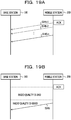
FIGs. 19A and 19B are diagrams illustrating an example of the solution for the Nagle-delay ACK problem. -
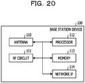
FIG. 20 is a diagram illustrating a hardware configuration example of a base station device. -
FIG. 21 is a diagram illustrating a hardware configuration example of a mobile station device. - Hereinafter, embodiments will be described in detail with reference to the drawings. Problems and embodiments of the present specification are exemplary and do not limit the scope of the rights of the present application. In particular, when the expressions are the same technically despite differences in the expressions of the description, the technology of the present application can be applied despite the different expressions and does not limit the scope of the rights.
- As terms used in the present specification or technical content described in the present specification, terms or technical content described in the specification may be appropriately used as a standard of communication in 3GPP or the like. As examples of the specification, there are
NPLs 1 to 12 described above. - For
NPLs 1 to 11 described above, the non-patent literatures described above may be used, but are frequently updated day by day. Thus, terms or technical content described inNPLs 1 to 11 issued immediately before the present application was filed may be appropriately used in the specification of the present application. - An overview of each of
NPLs 1 to 12 is as follows. - That is, NPL 1 (3GPP TS36.300 V12.5.0 (2015-03)) describes, for example, an overall specification of LTE-A.
- NPL 2 (3GPP TS36.211 V12.5.0 (2015-03)) describes, for example, the specification of a physical layer (PHY) channel (or a physical channel) of LTE-A.
- NPL 3 (3GPP TS36.212 V12.4.0 (2015-03)) describes, for example, the specification of PHY encoding of LTE-A.
- NPL 4 (3GPP TS36.213 V12.5.0 (2015-03)) describes, for example, the specification of a PHY procedure of LTE-A.
- NPL 5 (3GPP TS36.321 V12.5.0 (2015-03)) describes, for example, the specification of medium access control (MAC) of LTE-A.
- NPL 6 (3GPP TS36.322 V12.2.0 (2015-03)) describes, for example, the specification of radio link control (RLC) of LTE-A.
- NPL 7 (3GPP TS36.323 V12.3.0 (2015-03)) describes, for example, the specification of the packet data convergence protocol (PDCP) of LTE-A.
- NPL 8 (3GPP TS36.331 V12.5.0 (2015-03)) describes, for example, the specification of radio resource control (RRC) of LTE-A.
- NPL 9 (3GPP TS36.413 V12.5.0 (2015-03)) describes, for example, the specification of S1 of LTE-A.
- NPL 10 (3GPP TS36.423 V12.5.0 (2015-03)) describes, for example, the specification of X2 of LTE-A.
- NPL 11 (3GPP TR36.842 V12.0.0 (2013-12)) is, for example, a review report of a small cell technology of LTE-A.
- NPL 12 (RFC793) describes, for example, the specification of TCP.
-
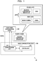
FIG. 1 is a diagram illustrating a configuration example of aradio communication system 10 according to the first embodiment. Aradio communication system 10 includes aradio communication device 500 and a firstradio communication device 600. Theradio communication device 500 and the firstradio communication device 600 execute radio communication. For example, theradio communication device 500 is a mobile station device and the first radio communication device is a base station device. - The
radio communication device 500 includes acommunication unit 510 and acontrol unit 520. - The
communication unit 510 transmits and receives a signal in a first layer and data of a second layer which is an upper layer of the first layer and delivery confirmation information for the data. - The
control unit 520 enables the delivery confirmation information to be transmitted from thecommunication unit 510 to the firstradio communication device 600 using a shared channel shared between a plurality of second radio communication devices including theradio communication device 500 based on a signal received from the firstradio communication device 600 without using scheduling information allocated to the firstradio communication device 600. - The
radio communication device 500 executes a scheduling request procedure with the firstradio communication device 600 when information is transmitted using the shared channel. In the scheduling request procedure, for example, the following procedure is executed. That is, when theradio communication device 500 transmits a scheduling request to the firstradio communication device 600 and the firstradio communication device 600 receives the scheduling request, scheduling information for theradio communication device 500 is generated. The firstradio communication device 600 transmits a UL grant including the scheduling information to theradio communication device 500, and then theradio communication device 500 transmits information using the shared channel according to the scheduling information. The transmission of the delivery confirmation information is delayed in some cases in accordance with the scheduling procedure. - In the first embodiment, the
radio communication device 500 can transmit delivery confirmation information of the second layer using the shared channel based on the signal transmitted from the firstradio communication device 600. Thus, theradio communication device 500 and the firstradio communication device 600 do not execute the scheduling request procedure, and theradio communication device 500 can transmit the delivery confirmation information using the shared channel. - Accordingly, in the first embodiment, in the
radio communication device 500, the scheduling request procedure for the transmission of the delivery confirmation information can be omitted, and thus it is possible to shorten a delay time in the transmission of the delivery confirmation information. In the first embodiment, by shortening the delay time, it is possible to achieve an improvement in throughput. - For example, as the delivery confirmation information, there is TCP ACK. Accordingly, in the first embodiment, it is possible to achieve shortening of the delay time in the transmission of the TCP ACK. In the first embodiment, by shortening the delay time, it is possible to achieve an improvement in throughput of TCP.
- Next, a second embodiment will be described.
-
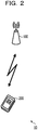
FIG. 2 illustrates a configuration example of theradio communication system 10. Theradio communication system 10 includes a base station device (hereinafter referred to as a "base station" in some cases) 100 and a mobile station device (hereinafter referred to as a "mobile station" in some cases) 200. - The
base station 100 corresponds to, for example, the firstradio communication device 600 according to the first embodiment. Themobile station 200 corresponds to, for example, theradio communication device 500 according to the first embodiment. - The
base station 100 is, for example, a radio communication device that executes radio communication with themobile station 200 which resides in a service zone of thebase station 100. - The
mobile station 200 is, for example, a radio communication device such as a smartphone, a feature phone, a tablet terminal, a personal computer, and a game device. Themobile station 200 executes radio communication with thebase station 100 and can is supplied with various services such as a calling service and a browsing service of a web page. - The
base station 100 and themobile station 200 can execute bidirectional communication. That is, communication in a direction from thebase station 100 to the mobile station 200 (hereinafter referred to as a "downlink (DL) direction" or a "downward direction" in some cases) and a direction from themobile station 200 to the base station 100 (hereinafter referred to as an "uplink (UL) direction" or an "upward direction" in some cases) is possible. - The
base station 100 executes allocation of radio resources or determination of an encoding scheme and a modulation scheme by executing scheduling in radio communication with themobile station 200 in the downward direction and the upward direction. Thebase station 100 transmits a control signal including scheduling information indicating a scheduling result to themobile station 200. Thebase station 100 and themobile station 200 execute radio communication according to the scheduling information included in the control signal. - In the
radio communication system 10 illustrated inFIG. 2 , an example in which onemobile station 200 executes radio communication with onebase station 100 will be described. However, for example, a plurality of mobile stations may execute radio communication with onebase station 100. Onemobile station 200 may execute radio communication with a plurality of base stations. In theradio communication system 10, a plurality of base stations and a plurality of mobile stations may be included. - Next, a configuration example of the
base station 100 will be described.FIG. 3 is a diagram illustrating a configuration example of thebase station 100. Thebase station 100 includes aradio transmission unit 101, aradio reception unit 102, acontrol unit 104, amemory unit 105, and anetwork communication unit 106. Theradio transmission unit 101 and theradio reception unit 102 may be included in a radio communication unit (or a communication unit) 103. - The
radio transmission unit 101 executes, for example, an error correction encoding process (hereinafter referred to as an encoding process in some cases), a modulation process, a frequency conversion process, and the like on data read form thememory unit 105 or a control signal output from thecontrol unit 104 to convert the data or the control signal into a radio signal. Theradio transmission unit 101 receives the scheduling information including the encoding rate, the modulation scheme, or the like from thecontrol unit 104 and executes an encoding process, a modulation process, and the like according to the scheduling information. Then, theradio transmission unit 101 transmits the converted radio signal to themobile station 200. In this case, theradio transmission unit 101 receives the scheduling information from thecontrol unit 104 and transmits the radio signal using radio resources included in the scheduling information. The radio resources include, for example, frequency and time resources. For example, theradio transmission unit 101 transmits data or the like using a physical downlink shared channel (PDSCH) and transmits the control signal or the like using a physical downlink control channel (PDCCH). - The
radio reception unit 102 receives, for example, a radio signal transmitted from eachmobile station 200 using radio resources included in the scheduling information received from thecontrol unit 104. In this case, theradio reception unit 102 receives a radio signal including the control signal or the like using a physical uplink control channel (PUCCH) and receives a radio signal including data using a physical uplink shared channel (PUSCH). Theradio reception unit 102 executes a frequency conversion process, a demodulation process, an error correction decoding process (hereinafter referred to as a "decoding process" in some cases), and the like on the received radio signal to extract the data, the control signal, and the like. Theradio reception unit 102 receives the scheduling information including the modulation scheme and the encoding rate from thecontrol unit 104 and executes the demodulation process, the decoding process, and the like according to the scheduling information. Theradio reception unit 102 outputs, for example, the extracted data, control signal, and the like to thememory unit 105 or thecontrol unit 104. - The
control unit 104 executes the above-described scheduling and outputs its result as scheduling information to theradio transmission unit 101 or theradio reception unit 102. Thecontrol unit 104 generates the control signal including the scheduling information and outputs the control signal to theradio transmission unit 101. The control signal is transmitted toward themobile station 200. - Further, the
control unit 104 executes retransmission control by a hybrid automatic repeat request (HARQ). The HARQ is, for example, a technology for decoding data which fails in the decoding process on a reception side by combining the data with data retransmitted from a transmission side without discarding the data. For example, when the decoding process for the data succeeds on the reception side, the reception side transmits acknowledgement (ACK: a positive response). When the transmission side receives ACK, the transmission side starts transmitting subsequent data. Conversely, when the decoding process fails on the reception side, the reception side responds to the transmission side with negative acknowledgement (NACK) and the transmission side receives NACK and retransmits the data. ACK and NACK by HARQ are examples of the delivery confirmation information by HARQ. Retransmission control by HARQ is executed between thebase station 100 and themobile station 200. - A target of the retransmission control by HARQ is, for example, data in a medium access control (MAC) layer. A MAC packet data unit (MAC PDU) is an example of the data. The MAC layer is included in the data link layer (Layer 2) of the OSI reference model.
- The
control unit 104 executes, for example, retransmission control by HARQ as follows. That is, theradio reception unit 102 notifies thecontrol unit 104 of a processing result indicating whether data can correctly be decoded when the decoding process is executed based on a cyclic redundancy check (CRC) or the like added to the data of the MAC layer. Thecontrol unit 104 generates ACK or NACK according to the processing result. Thecontrol unit 104 transmits ACK by HARQ (hereinafter referred to as "HARQ ACK" in some cases) or NACK by HARQ (hereinafter referred to as "HARQ NACK" in some cases) to themobile station 200 via theradio transmission unit 101. On the other hand, when HARQ ACK is received from thebase station 200 via theradio reception unit 102, thecontrol unit 104 starts transmitting subsequent data. When HARQ NACK is received from themobile station 200 via theradio reception unit 102 or when HARQ ACK is not received although a given time has passed after transmission of the data of the MAC layer, thecontrol unit 104 reads the data for which HARQ ACK is not confirmed from thememory unit 105 and retransmits the data to themobile station 200. - The
memory unit 105 stores, for example, the data, the control signal, and the like. For example, theradio reception unit 102, thecontrol unit 104, and thenetwork communication unit 106 appropriately store the data, the control signal, and the like in thememory unit 105. Theradio transmission unit 101, thecontrol unit 104, and thenetwork communication unit 106 appropriately read the data, the control signal, and the like stored in thememory unit 105. - The
network communication unit 106 is connected to another device and transmits and receives data or the like to and from the other device. At this time, thenetwork communication unit 106 converts the data into packet data with a format which can be output to the other device and transmits the packet data to the other device, or extracts data or the like from packet data received from the other device and outputs the data or the like to thememory unit 105, thecontrol unit 104, or the like. Examples of the other device include another base station device, a mobility management entity (MME), or a serving gateway (SGW). -
FIG. 4 is a diagram illustrating a configuration example of themobile station 200. Themobile station 200 includes aradio transmission unit 201, aradio reception unit 202, acontrol unit 204, and amemory unit 205. Theradio transmission unit 201 and theradio reception unit 202 may be included in a radio communication unit (or a communication unit) 203. - The
communication unit 203 corresponds to, for example, thecommunication unit 510 according to the first embodiment. Thecontrol unit 204 corresponds to, for example, thecontrol unit 204 according to the first embodiment. - For example, the
radio transmission unit 201 executes an encoding process, a modulation process, a frequency conversion process, and the like on the data read from thememory unit 205 or the control signal or the like output from thecontrol unit 204 to convert the data, or the control, or the like into a radio signal. Theradio transmission unit 201 receives scheduling information including the encoding rate or the modulation scheme from thecontrol unit 204 and executes the encoding process or the modulation process according to the scheduling information. Theradio transmission unit 201 transmits the radio signal to thebase station 100. In this case, theradio transmission unit 201 receives the scheduling information including the radio resources allocated to themobile station 200 from thecontrol unit 204 and transmits the radio signal to thebase station 100 using the radio resources. For example, theradio transmission unit 201 transmits the control signal or the like using the PUCCH and transmits data or the like using the PUSCH. - The
radio reception unit 202 receives the radio signal transmitted from thebase station 100. At this time, theradio reception unit 202 receives the scheduling information including the radio resources allocated to themobile station 200 from thecontrol unit 204 and receives the radio signal using the radio resources. For example, theradio reception unit 202 receives the radio signal including the control signal or the like using the PDCCH and receives the radio signal including the data or the like using the PDSCH. Theradio reception unit 202 executes the frequency conversion process, the demodulation process, the decoding process, and the like on the received radio signal to extract the data, the control signal, and the like from the radio signal. At this time, theradio reception unit 202 receives the scheduling information such as the modulation scheme or the encoding rate from thecontrol unit 204 and executes the demodulation process or the decoding process according to the modulation scheme, the encoding rate, and the like. For example, theradio reception unit 202 outputs the extracted data, control signal, and the like to thecontrol unit 204 or thememory unit 205. - The
control unit 204 receives the control signal from theradio reception unit 202, extracts the scheduling information or the like allocated to themobile station 200 from the control signal, and outputs the scheduling information or the like to theradio transmission unit 201 or theradio reception unit 202. - The
control unit 204 generates a control signal or the like and outputs the control signal or the like to theradio transmission unit 201. The control signal may include, for example, HARQ ACK or HARQ NACK, channel state information (CSI), and a scheduling request (SR). - Further, the
control unit 204 executes delivery confirmation (or response confirmation) and a retransmission process for TCP data. For example, the TCP data is exchanged between themobile station 200 and a server that handles TCP via thebase station 100. In this case, in principle, thebase station 100 transmits a TCP packet transmitted from the server to themobile station 200 or transmits a TCP packet transmitted from themobile station 200 to the server without analyzing a TCP header or TCP data included in the TCP packet. - Even in retransmission of TCP, when a TCP reception side can correctly receive TCP data transmitted from a TCP transmission side, the TCP reception side responds to the TCP transmission side with TCP ACK (or a positive response). When the TCP ACK is received, the TCP transmission side starts transmitting subsequent TCP data. Conversely, when the TCP ACK is not received although a given time has passed after the transmission of the TCP data, the TCP transmission side retransmits the TCP data for which the TCP ACK is not confirmed to the reception side. In this case, for example, the TCP transmission side may determine that the TCP data may not correctly be received by the TCP reception side when receiving a plurality (for example, 3) of TCP ACKs (or repeated ACK) with the same confirmation response number, and may retransmit the TCP data. The retransmission process by TCP is executed by, for example, the
control unit 204. In this case, thecontrol unit 204 confirms whether the TCP data can correctly be received, generates delivery confirmation information of TCP according to a result, and transmits the delivery confirmation information to the server via theradio transmission unit 101. When the TCP ACK may not b received although a given time has passed after transmission of the TCP data to the server or the like via theradio transmission unit 101, thecontrol unit 204 reads the TCP data for which the TCP ACK stored in thememory unit 205 may not be confirmed and transmits the TCP data to the server via theradio transmission unit 101. - TCP is included in the transport layer (Layer 4) of the OSI reference model. On the other hand, the MAC layer in which HARQ ACK or the like is handled is included in the data link layer (Layer 2) of the OSI reference model. The transport layer is an upper layer of the data link layer.
- A radio link control (RLC) layer and a packet data convergence protocol (PDCP) layer in LTE or the like are included in the data link layer and are sublayers of the data link layer. For the MAC layer, an RCL layer, and the PDCP layer, the MAC layer is a lower layer and the PDCP layer is an upper layer in these layers.
- For example, the
control unit 204 can receive data of the MAC layer from theradio reception unit 202, can generate or extract data of each layer from data of the MAC layer to TCP data, and subsequently can execute a process on the TCP data. For example, thecontrol unit 204 can transmit the data of the MAC layer to thebase station 100 by generating or extracting the data of each layer from the TCP data to the data of the MAC layer and subsequently outputting the data of the MAC layer to theradio transmission unit 201. - Further, the
control unit 204 executes retransmission control by HARQ. The retransmission control by HARQ is executed between thebase station 100 and themobile station 200. For example, thecontrol unit 204 and the like execute the following process. That is, theradio reception unit 202 notifies thecontrol unit 204 of a processing result indicating whether data can correctly be decoded when the decoding process is executed based on a CRC or the like added to the data of the MAC layer. Thecontrol unit 204 generates HARQ ACK or HARQ NACK according to the processing result. Thecontrol unit 204 transmits HAR ACK or HARQ NACK to thebase station 100 via theradio transmission unit 201. On the other hand, when HARQ ACK is received from thebase station 100 via theradio reception unit 202, thecontrol unit 204 starts transmitting subsequent data of the MAC layer. When HARQ NACK is received from thebase station 100 or HARQ ACK is not received although a given time has passed after the transmission of the data of the MAC layer, thecontrol unit 204 reads the data for which HARQ ACK is not confirmed from thememory unit 205 and retransmits the data to thebase station 100. - The
memory unit 205 stores, for example, the data, the control signal, and the like. For example, theradio reception unit 202 or thecontrol unit 204 appropriately stores the data, the control signal, and the like in thememory unit 205. Theradio transmission unit 201 or thecontrol unit 204 appropriately reads the data, the control signal, and the like stored in thememory unit 205. - In the
base station 100 or themobile station 200, for example, information processed before modulation or after decoding is referred to as data or control information in some cases, and information processed after modulation or before decoding is referred to as a signal in some cases. Alternatively, for example, information handled in the transport layer is also referred to as data, control information, or the like in some cases and information handled in the MAC layer is referred to as a signal in some cases. - Next, an example of an operation will be described. First, a transmission example of TCP ACK in the
mobile station 200 will be described. Next, an example of an operation in the second embodiment will be described. -
FIGs. 5A to 6 are diagrams illustrating a transmission example of TCP ACK. As illustrated inFIG. 5A , when themobile station 200 normally receives TCP data transmitted in the downward direction ("DL TCP data") (S1), themobile station 200 generates TCP ACK. Themobile station 200 transmits the generated TCP ACK ("UL TCP ACK") in the upward direction (S2). As described above, the TCP data is generated by, for example, a server or the like connected to thebase station 100 and is transmitted to themobile station 200 via thebase station 100. TCP ACK is also transmitted toward the server generating the TCP data via thebase station 100. - In this case, the
mobile station 200 executes, for example, a scheduling request procedure illustrated inFIG. 5B to transmit TCP ACK. - That is, the
mobile station 200 transmits the scheduling request (SR) to thebase station 100 using the PUCCH (S5). Thebase station 100 receives the scheduling request and generates the scheduling information. Thebase station 100 transmits a UL grant (or transmission permission) including the scheduling information to themobile station 200 using the PDCCH (S6). Themobile station 200 transmits TCP ACK to themobile station 200 using the radio resources of the PUSCH allocated with the scheduling information (S7). The example ofFIG. 5B is an example in which themobile station 200 transmits TCP ACK and a buffer status report (BSR) to thebase station 100. -
FIG. 6A illustrates a sequence example of a series of processes until themobile station 200 can transmit data in the upward direction andFIG. 6B illustrates an example of a time taken for themobile station 200 to transmit data in the upward direction. - For example, when data occurs, the mobile station (user equipment (UE)) 200 waits for an opportunity to transmit the PUCCH (S11) and transmits the scheduling request using the PUCCH (S12). The base station (evolved Node B (eNB)) 100 executes a process of allocating radio resources or the like (S13) and transmits a UL grant (S14). The
mobile station 200 receives the UL grant, executes a process on the data, such as an encoding process (S15), and transmits the data ("UL data") using the radio resources included in the PUSCH (S16). An example of the UL data includes TCP ACK. -
FIG. 6B illustrates an example of an elapsed time in each process of S11 to S16 in the sequence of the series of the processes. For example, an average delay time in the process of S11 is "2.5 ms" or the like. As illustrated inFIG. 6B , a delay time until onemobile station 200 transmits the data in the upward direction is assumed to be about "11.5 ms" despite being error-free. That is, a delay time taken to transmit TCP ACK is assumed to be about "11.5 ms". The delay time has a considerable influence on TCP communication and is one factor which deteriorates throughput in TCP. As a simply reference example, for example, a round-trip time (RTT) on an Internet circuit from Tokyo to Osaka was about 20 ms. The magnitude of "11.5 ms" can also be understood from the reference value. - For example, the
mobile station 200 can also transmit TCP ACK using the PUCCH. However, themobile station 200 may not transmit TCP ACK at a timing at which TCP ACK is desired to be transmitted in some cases, for example, when the PUCCH is not set in a subframe with which TCP ACK is desired to be transmitted or radio resources of the PUCCH used to transmit other signals lack. In this case, as illustrated inFIG. 7 , themobile station 200 waits for transmission of TCP ACK until a subsequent opportunity (for example, after 5 ms) of the PUCCH, and thus transmission delay of TCP ACK increases. - Accordingly, in the second embodiment, the
mobile station 200 transmits TCP ACK using the PUSCH without executing the scheduling request procedure. Thus, the scheduling request procedure illustrated inFIG. 5B or6A is omitted, and thus it is possible to short the delay time taken to transmit TCP ACK. By shorting the delay time of TCP ACK, it is also possible to improve throughput in TCP. - In the second embodiment, when TCP ACK is transmitted using the PUSCH, the
mobile station 200 does not execute the scheduling request procedure. Therefore, no UL grant is given from thebase station 100. Therefore, themobile station 200 transmits TCP ACK using the PUSCH based on a signal transmitted from thebase station 100 without receiving the UL grant (or without using scheduling information). Specifically, there are eight methods as follows. Hereinafter, the methods will be described in sequence. - (1) Determination of a PUSCH physical resource block (PRB) index based on a PDCCH lowest control channel element (CCE) index = k
- (2) Determination of a modulation and coding scheme (MCS) index from relation between PDCCH aggregation level and a PUSCH MCS index
- (3) Value of cyclic shift of PUSCH demodulation reference signal (DMRS) as a fixed value
- (4) Presetting of transmission timing of the PUSCH of TCP ACK by radio resource control (RRC)
- (5) Improvement in (1)
- (6) Improvement in (4)
- (7) execution of semi-persistent scheduling (SPS) for transmitting TCP ACK
- (8) Others
-
FIG. 8 is a diagram illustrating a transmission example of TCP ACK when the PUSCH PRB index is determined based on the PDCCH lowest CCE index = k. When the PDCCH is received (S30), themobile station 200 determines (or selects) a position g of the radio resource of the PUSCH with which TCP ACK is transmitted, based on the first CCE index (lowest CCE index) of the CCEs included in the PDCCH. Themobile station 200 transmits TCP ACK using the radio resource of the determined position g. Thebase station 100 receives TCP ACK using the radio resource. - The CCE is, for example, a unit (or component) of a radio resource used to transmit the PDCCH. The
base station 100 allocates, for example, 1, 2, 4, or 8 continuous CCEs for eachmobile station 200. Thebase station 100 transmits a control signal or the like destined for themobile station 200 using the allocated CCEs. The number of CCEs is equivalent to an aggregation level. For example, when the number of CCEs is 8, the aggregation level is 8. Thebase station 100 can determine the number of CCEs so that the encoding rate decreases as the number of CCEs included in one PDCCH increases. Thebase station 100 may determine the number of CCEs allocated to onebase station 200 based on radio quality. -
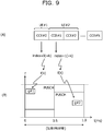
FIG. 9(A) , which is a section (A) ofFIG.9 , illustrates an example of the CCEs allocated to eachmobile station 200 by thebase station 100. In the example ofFIG. 9(A) , thebase station 100 allocates CCE (CCE # 0) with a CCE index of "0" (or an index: hereinafter referred to as a "CCE index" in some cases) to a mobile station 200-1 (UE # 1). Thebase station 100 allocates to two CCEs (CCE # 1 and CCE # 2) with CCE indexes of "1" and "2" to the mobile station 200-2 (UE # 2). For example, thebase station 100 allocates the CCE indexes to a plurality of users (or the mobile stations 200) multiplexed in the same subframe so that the same CCE index is repeated. Themobile station 200 executes, for example, a decoding process or the like on all CCEs (or CCEs within a given candidate range) to detect CCEs which can correctly be decoded as CCEs which can be allocated to the mobile station. In this case, themobile station 200 can also specify the CCE indexes according to the number of CCEs which can correctly be decoded. For example, when the number of CCEs which can correctly be decoded is 1, the CCE isCCE # 0. When the number of CCEs which can correctly be decoded is 2, the CCEs areCCE # 1 and CCE # 2). This detection is referred to as, for example, blind detection (or blind decoding) in some cases. - The
mobile station 200 determines the resource position g of the PUSCH used to transmit TCP ACK using the first CCE index k among the CCE indexes detected through the blind detection in this way. For example, as illustrated inFIG. 9(B) (i.e. a section (B) ofFIG.9 ), when the first CCE index k for the mobile station 200-1 is "0", theposition g # 1 in the PUSCH is determined as a radio resource used to transmit TCP ACK by f(0). When the first CCE index k for the mobile station 200-2 is "1",g # 2 in the PUSCH is determined as a radio resource used to transmit TCP ACK by f(1). The function f may be determined as a system or may be determined for each of the mobile stations 200-1 and 200-2. - Referring back to
FIG. 8 , themobile station 200 transmits TCP ACK using the position g of the radio resource of the PUSCH determined by f(k) (S31). -
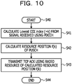
FIG. 10 is a flowchart illustrating an example of an operation in themobile station 200. InFIG. 10 , the example of the operation described above is collected. - When the
mobile station 200 starts a process (S40), themobile station 200 detects the first CCE index k among the CCE indexes allocated to themobile stations 200 from the signal received using the PDCCH (S41). For example, theradio reception unit 202 detects the first CCE index k through the blind detection on the signal received using the PDCCH and outputs the detected CCE index k to thecontrol unit 204. - Subsequently, the
mobile station 200 calculates the resource position g = f(k) in the PUSCH based on the detected first CCE index k (S42). For example, thecontrol unit 204 calculates the resource position g by reading an expression indicating the function f stored in thememory unit 205 and substituting the first CCE index k to the function f received from theradio reception unit 202. - Subsequently, the
mobile station 200 transmits TCP ACK using the radio resource of the calculated resource position g of the PUSCH (S43). For example, the following process is performed. That is, thecontrol unit 204 outputs the resource position f(k) to theradio transmission unit 201. Thecontrol unit 204 generates TCP ACK and outputs the data of the MAC layer corresponding to the generated TCP ACK to theradio transmission unit 201. Theradio transmission unit 201 executes the encoding process, the modulation process, and the like on the data to convert the data into the radio signal and transmits the radio signal to thebase station 100 using the radio resource at the resource position g of the PUSCH. Thus, TCP ACK is transmitted to thebase station 100 using the PUSCCH. -
FIG. 11A illustrates an example of a correspondent relation between a PDCCH aggregation level (or an aggregation level: hereinafter referred to as an "aggregation level" in some cases) and the PUSCH MCS index. For example, the correspondent relation between the aggregation level and the PUCH MCS index is determined in advance. Then, themobile station 200 determines MCS based on the aggregation level using the correspondent relation. MCS (or an MCS level value) indicates, for example, a combination of the encoding rate and the modulation scheme. - In the correspondent relation, for example, the PUSCH MCS level value is smaller as the aggregation level value is larger. The PUSCH MCS level value is larger as the aggregation level value is smaller. In other words, when the aggregation level value is greater than a first threshold, the MCS level value is less than a second threshold. Conversely, when the aggregation level value is equal to or less than the first threshold, the MCS level value is equal to or greater than the second threshold.
- Alternatively, when the aggregation level value increases over time, the PUSCH MCS level value decreases. When the aggregation level value decreases, the PUSCH MCS level value increases.
- In the example of
FIG. 11A , the aggregation level value is "1" and the PUSCH MCS level value is "x1" in mobilestation UE # 1. In mobilestation UE # 2, the aggregation level value is "2" and the PUSCH MCS level value is "x2" (< x1) in mobilestation UE # 2. - As illustrated in
FIG. 11A , the aggregation level (or the aggregation level value) corresponds to, for example, the number of CCEs allocated to themobile station 200. In the example ofFIG. 11A , since the number of CCEs allocated toUE # 1 is "1", the aggregation level is "1" inUE # 1. Since the number of CCEs allocated toUE # 2 is "2", the aggregation level is "2" inUE # 2. - For example, the
mobile station 200 may execute the following process. That is, based on the determined correspondent relation, the PUSCH MCS level value corresponding to the aggregation level value is stored in thememory unit 205. Alternatively, thememory unit 205 may store the correspondent relation. Then, thecontrol unit 204 of themobile station 200 reads the PUSCH MCS level value corresponding to the aggregation level value detected in the blind decoding from thememory unit 205. Thecontrol unit 204 outputs the read PUSCH MCS level value to theradio transmission unit 201 and theradio transmission unit 201 executes the encoding process, the modulation process, and the like on TCP ACK based on the PUSCH MCS level value and transmits TCP ACK to thebase station 100. - For example, the
mobile station 200 uses a cyclic shift sequence obtained by executing cyclic shift on a Zadoff-Chu (ZC) sequence based on a value of the cyclic shift included in the UL grant for a data decoding reference signal (DMRS). In the second embodiment, since the UL grant is not used, a fixed value C determined in advance is used as the value of the cyclic shift in themobile station 200. Thus, for example, thebase station 100 can easily detect a data decoding reference signal and can easily also decode the data transmitted from themobile station 200 using the detected data decoding reference signal. For example, thecontrol unit 204 reads the fixed value C stored in thememory unit 205, generates a sequence such as the ZC sequence, and the sequence obtained through the cyclic shift based on the fixed value C is used as the data decoding reference signal. -
FIG. 12 is a diagram illustrating a transmission example of TCP ACK when a transmission timing of TCP ACK is set by RRC. Thebase station 100 and themobile station 200 transmit and receive a signal in a determined procedure in some cases, for example, when themobile station 200 waits or a new radio connection is established. The procedure may be, for example, a procedure defined in the specification including the above-described non-patent literature. An example of the procedure includes an RRC procedure. - In the second embodiment, the
base station 100 notifies themobile station 200 of the transmission timing of TCP ACK in the PUSCH using a signal transmitted and received in the procedure, and then themobile station 200 transmits TCP ACK at a predetermined timing based on the signal. - For example, the
base station 100 and themobile station 200 execute the following process. That is, thecontrol unit 104 of thebase station 100 determines a transmission timing at which TCP ACK is transmitted and instructs theradio transmission unit 101 to generate a signal including information regarding the determined timing. Theradio transmission unit 101 generates the signal according to the instruction and transmits the signal according to the determined procedure. Theradio reception unit 202 of themobile station 200 receives the signal, extracts information regarding the transmission timing from the received signal, and outputs the information to thecontrol unit 204. Thecontrol unit 204 outputs the extracted information regarding the transmission timing to theradio transmission unit 201 and transmits TCP ACK to theradio transmission unit 201 according to the timing (S61). - For example, the information notified of with the signal of the determined procedure may be a frequency used to transmit TCP ACK in addition to the transmission timing or a part or all of the information regarding the radio resources may be notified of.
- In (1) described above, the position of the radio resource used to transmit TCP ACK in the PUSCH has been determined based on the PDCCH lowest CCE index = k. This example is an example in which (1) described above is improved and the position of a radio resource (PRB) of the PUSCH used to transmit TCP ACK is set based on a signal transmitted and received in the procedure determined in advance. The procedure may be a procedure defined in the specification including the above-described non-patent literature, like (4) described above. An example of the procedure includes an RRC procedure.
- The position of the PRB notified of in the procedure may be a start position or an end position of the PRB transmitted with TCP ACK or the position of the PRB in the PUSCH used to transmit TCP ACK may be indicated. In this example, content described in (4) described above,
FIG. 12 , and the like are quoted. In this case, when the signal by the determined procedure is received, thecontrol unit 204 instructs theradio transmission unit 201 to transmit TCP ACK using the radio resource located at a predetermined position of the PUSCH based on the signal. Theradio transmission unit 201 transmits TCP ACK using the radio resource according to the instruction. - In (4) described above, the example in which the transmission timing of TCP ACK is set in advance with the signal transmitted and received in the procedure determined in advance using the PUSCH has been described. This example is an example in which the
base station 100 estimates a timing at which TCP ACK occurs in themobile station 200 and sets a transmission timing of the PDCCH, and themobile station 200 transmits TCP ACK using the PUSCH based on the timing. -
FIGs. 13 and14 are diagrams illustrating transmission examples of TCP ACK in this example. For example, certain TCP data is divided into a plurality (for example, n) of PDCP service data unit (SDU) (or packet units) and is transmitted from thebase station 100 to themobile station 200 in some cases. - In this case, the
base station 100 masks (or scrambles: hereinafter referred to as "masks" in some cases) the PDCCH used to transmit a control signal for giving an instruction to transmit first PDCP SDU to (n-1)-th PDCP SDU with a cell-radio network temporary identifier (C-RNTI). Specifically, thebase station 100 masks CRC added to the control signal with C-RNTI. Thebase station 100 transmits the control signal masked with C-RNTI using the PDCCH (S70-1, ..., S70-(n-1) ofFIG. 14 ). In this case, when themobile station 200 receives the control signal masked with C-RNTI and decodes (or descrambles: hereinafter referred to as "decodes" in some cases) the control signal with C-RNTI, themobile station 200 recognizes that the first to (n-1)-th PDCP SDUs are transmitted and recognizes that the transmission timing of TCP ACK does not come. - On the other hand, the
base station 100 masks the PDCCH used to transmit the control signal for giving an instruction to transmit the final n-th PDCP SDU with a transmission control protocol-cell radio network temporary identifier (TCP-CRNTI) different from C-RNTI. Specifically, thebase station 100 masks CRC added to the control signal with TCP-CRNTI. Thebase station 100 transmits the control signal masked with TCP-CRNTI using the PDCCH (S70 ofFIG. 13 and S70-n ofFIG. 14 ). In this case, when themobile station 200 can receive the control signal masked with TCP-CRNTI and decode the control signal with TCP-RNTI, themobile station 200 recognizes the final n-th PDCP SDU and recognizes that the transmission timing of TCP ACK is notified of. The control signal masked with TCP-RNTI indicates that, for example, the transmission timing of TCP ACK comes in themobile station 200. - Then, the
mobile station 200 may determine the resource position g of the PUSCH used to transmit TCP ACK based on the minimum CCE index among CCEs included in the PDCCH used to receive the control signal like (1) described above. Themobile station 200 transmits TCP ACK using the radio resource of the resource position g. - The above-described process may be executed, for example, in the
control unit 104 of thebase station 100 or thecontrol unit 204 of themobile station 200. For example, the process is executed as follows. That is, thecontrol unit 104 analyzes a data amount of TCP data transmitted to themobile station 200 by analyzing TCP data or a TCP header. When the data amount reaches a predetermined value and a timing at which themobile station 200 transmits TCP ACK comes, thecontrol unit 104 generates the control signal. Thecontrol unit 104 masks CRC added to the control signal with TCP-RNTI along with TCP-CRNTI read from thememory unit 105 and instructs theradio transmission unit 101 to transmit the control signal masked with TCP-CRNTI to themobile station 200. Theradio transmission unit 101 masks CRC of the control signal with TCP-RNTI according to the instruction and transmits the masked signal to themobile station 200. When theradio reception unit 202 of themobile station 200 can decode the signal using TCP-CRNTI, theradio reception unit 202 notifies thecontrol unit 204 that the signal is decoded and thecontrol unit 204 recognizes that a transmission timing of TCP ACK comes by the notification. Thecontrol unit 204 instructs theradio transmission unit 201 to transmit TCP ACK. Theradio transmission unit 201 transmits TCP ACK to thebase station 100 according to the instruction. In the process of the case of C-RNTI, the foregoing "TCP-CNTI" may be substituted with C-RNTI. In this case, when theradio reception unit 202 notifies thecontrol unit 204 that the signal can be decoded with C-RNTI, thecontrol unit 204 recognizes that a transmission timing of TCP ACK does not come. - In this example, the
base station 100 can confirm the final PDCP SDU or the like, for example, by analyzing the TCP header or the TCP data. To reduce overhead of the analysis of the TCP header or the TCP data, only a quality of service class identifier (QCI: Qos class indicator) 6, QCI 8, or QCI 9 may be analyzed. From the viewpoint of bearers, bearers that execute the present application can also be set separate bearers. For example, a bearer that transmits data using C-RNTI and a bearer that transmits data using TCP-RNTI may be set as different bearers. - The
base station 100 can estimate a timing at which TCP ACK is transmitted by themobile station 200. For example, when the number of packets reaches a predetermined number, the control signal masked with TCP-CRNTI may be transmitted with the PDCCH at the timing. - This example is an example of transmission executed using SPS at the time of transmitting TCP ACK. SPS is, for example, a scheduling scheme of allocating radio resources semi-persistently rather than allocating the radio resources dynamically for each subframe as in dynamic scheduling. In SPS, the
base station 100 may transmit scheduling information to themobile station 200 for each given period. Therefore, it is possible to achieve a reduction in overhead by transmitting the control signal. -
FIG. 15 is a diagram illustrating a transmission example of TCP ACK in this example. When TCP data is transmitted, thebase station 100 simultaneously transmits an SPS activation and executes SPS (S110). The SPS activation is, for example, information indicating that SPS is executed (or started). For example, thecontrol unit 104 generates the SPS activation and outputs the SPS activation to theradio transmission unit 101, and theradio transmission unit 101 transmits the SPS activation using the PDCCH. At this time, thecontrol unit 104 also generates information such as a period of SPS and transmits the information with the PDCCH via theradio transmission unit 101. - The
base station 200 receives the SPS activation, thus determines to execute SPS, and transmits TCP ACK at the period received from thebase station 100 using the PUSCH (S111). For example, themobile station 200 executes the following process. That is, when thecontrol unit 204 of themobile station 200 receives the SPS activation and the period of SPS via theradio reception unit 202, thecontrol unit 204 instructs theradio transmission unit 201 to transmit TCP ACK at each period. Theradio transmission unit 201 transmits TCP ACK according to the instruction. In this case, themobile station 200 may receive the SPS activation, may subsequently transmit the first TCP ACK after 4 ms, and subsequently may transmit TCP ACK at each period (or each regulated interval) of SPS. - SPS is used in some cases, for example, when the
mobile station 200 transmits voice over Internet protocol (VoIP) data. Thebase station 100 masks the PDCCH with which the SPS activation is transmitted with TCP-CRNT for transmission so that the VoIP data is not incorrectly transmitted in themobile station 200. Themobile station 200 can recognize SPS by TCP ACK when the signal received with the PDCCH can be decoded with TCP-CRNTI, and can recognize that the VoIP data can be transmitted when the signal may not be decoded with TCP-CRNTI. In the process by thebase station 100 and themobile station 200 in this case, for example, the content described in (6) described above is quoted. - When the
mobile station 200 transmits TCP ACK using the PUSCH, themobile station 200 can also execute power control of the PUSCH. Thebase station 200 may calculate transmission power for the PUSCH (or TCP ACK) based on a value of transmission power control (TPC) transmitted from thebase station 100 using the PDCCH. Alternatively, themobile station 200 may calculate the transmission power based on transmission power of the PUCCH (or a signal transmitted using the PUCCH) immediately before the PUSCH with which TCP ACK is transmitted. - As described above, in the second embodiment, the
mobile station 200 can transmit TCP ACK using the PUSCH without executing the scheduling request procedure (for example, S11 to S16 ofFIG. 6 ). Accordingly, it is possible to also shorten a delay time (in the example ofFIG. 6B , "11.5 ms") from occurrence of the TCP data to transmission of TCP ACK. The delay time of TCP ACK can be shortened up to about "4 ms". The throughput of TCP increases in reverse proportion to a decrease in RTT and the effect of increasing the throughput of TCP in accordance with this scheme is twice or more than when the scheduling request procedure is executed (for example,FIG. 6A ). - Next, a Nagle-delay ACK problem and solutions thereto will be described.
FIGs. 16 to 19B are diagrams illustrating the problem and solutions thereto. First, delay ACK will be described. -
FIG. 16 is a diagram illustrating the delay ACK. As illustrated inFIG. 16 , aTCP reception side 400 responds with TCP ACK when theTCP reception side 400 can normally receive TCP data transmitted from aTCP transmission side 300. In this case, when theTCP reception side 400 receives TCP data with a largest segment size or more, theTCP reception side 400 receives two segments of the TCP data (S130 and S131) and recommends transmitting TCP ACK (or executes mounting for the transmission) (S132). Since theTCP reception side 400 receives the TCP data of the two segments and transmits TCP ACK, there is the advantage of enabling an opportunity to update a TCP reception window to be given. -
FIG. 17 is a diagram illustrating the Nagle-delay ACK problem. For example, when there are many small pieces of TCP data, theTCP transmission side 300 does not the small pieces of TCP data one by one but collectively transmit the plurality of small pieces of TCP data as one piece of TCP data (S135 and S136). In this way, an algorithm for collectively transmitting the plurality of pieces of data as one piece of data is referred to as, for example, a Nagle algorithm in some cases. In this case, it takes a time equal to or greater than a given time until theTCP transmission side 300 collectively transmits the TCP data as one piece of data (S135 and S136). Then, as described in the delay ACK, in order to theTCP reception side 400 to receive the TCP data of two segments and transmit TCP ACK, it takes a considerably long time equal to or greater than a threshold until theTCP transmission side 300 receives TCP ACK in some cases. In this way, the problem that it takes a considerably long time in order for theTCP transmission side 300 to receive TCP ACK is referred to as, for example, a Nagle-delay ACK problem in some cases. - In the second embodiment, two solutions to the Nagle-delay ACK problem will be described.
-
FIG. 18 is a diagram illustrating a first example of the solutions. InFIG. 18 , themobile station 200 is exemplified as theTCP reception side 400. When the TCP data of one segment is received from the TCP transmission side 300 (S140), thebase station 100 segments the TCP data into a plurality of pieces of data to transmit the TCP data to the mobile station 200 (S141). - When the plurality of segmented pieces of data are received, the
mobile station 200 stops the delay ACK. When the TCP data of one segment is received, themobile station 200 responds with TCP ACK (S145). Thus, for example, in theTCP transmission side 300, transmission delay of TCP ACK can be shortened compared to when themobile station 200 receives two segments and responds with TCP ACK (S144). -
FIGs. 19A and 19B are diagrams illustrating a second example of the solutions. The second example is an example in which themobile station 200 transmits TCP ACK when radio quality is good. For example, when themobile station 200 transmits TCP ACK and quality of an upward radio line is not good, TCP ACK is transmitted repeatedly several times in some cases (S145-1, S145-2, ..., S145-n ofFIG. 19A ). In this case, in thebase station 100 or theTCP transmission side 300, transmission delay of TCP ACK occurs. - Accordingly, when the radio quality is equal to or less than given quality, the
mobile station 200 does not transmit TCP ACK. When the radio quality is higher than the given quality, themobile station 200 collectively transmits TCP ACK (S146 ofFIG. 19B ). In themobile station 200, TCP ACK is not transmitted several times and it is possible to achieve a reduction in power consumption of themobile station 200. -
FIG. 20 is a diagram illustrating a hardware configuration example of thebase station 100. Thebase station 100 includes anantenna 110, a radio frequency (RF)circuit 111, aprocessor 112, amemory 113, a network interface (IF) 114. Theprocessor 112 can realize the function of thecontrol unit 104 by reading and executing a program stored in thememory 113. Theprocessor 112 corresponds to, for example, thecontrol unit 104 in the second embodiment. Theantenna 110 and theRF circuit 111 correspond to, for example, theradio transmission unit 101 and theradio reception unit 102 in the second embodiment. Further, thememory 113 corresponds to, for example, thememory unit 105 in the second embodiment. Furthermore, the network IF 114 corresponds to, for example, thenetwork communication unit 106 in the second embodiment. -
FIG. 21 is a diagram illustrating a hardware configuration example of themobile station 200. Themobile station 200 includes anantenna 210, anRF circuit 211, aprocessor 212, and amemory 213. Theprocessor 212 can realize the function of thecontrol unit 204 by reading and executing a program stored in thememory 213. Theprocessor 212 corresponds to, for example, thecontrol unit 204 in the second embodiment. Theantenna 210 and theRF circuit 211 correspond to, for example, theradio transmission unit 201 and theradio reception unit 202 in the second embodiment. Further, thememory 213 corresponds to, for example, thememory unit 205 in the second embodiment. - The
processors - In the above-described example, the example in which the
mobile station 200 determines the resource position of the PUCCH used to transmit TCP ACK based on the smallest CCE index k among CCEs allocated to themobile station 200 has been described (for example,FIG. 9(B) ). For example, themobile station 200 may determine the resource position of the PUCCH used to transmit TCP ACK based on the largest CCE index among CCEs allocated to themobile station 200. For example, themobile station 200 may transmit TCP ACK using the radio resource of the PUCCH corresponding to the CCE index of CCE allocated to themobile station 200. - In the above-described example, TCP has been described as an example. For example, as long as a protocol such as the stream control transmission protocol (SCTP) that transmits and receives the delivery confirmation information in a end-to-end scheme and ensures reliability of communication can be used, the above-described example can be realized. Even in this case, by realizing the above-described example, it is possible to shorten the delay time taken to transmit the delivery confirmation information in accordance with the protocol and achieve an improvement in throughput of communication using the protocol.
- Further, in the above-described example, the example in which TCP ACK is mainly transmitted has been described. For example, even when the
mobile station 200 transmits TCP NACK, it is possible to transmit TCP NACK as in the case in which TCP ACK is transmitted. - The above-described embodiments can also be combined in any manner. For example, the following combinations can be realized.
- That is, the first and second embodiments can be combined to be realized. In this case, the
radio communication device 500 and the firstradio communication device 600 described in the first embodiment can also be realized as thebase station device 100 and themobile station device 200, described in the second embodiment, respectively. Alternatively, theradio communication device 500 and the firstradio communication device 600 described in the first embodiment can also be realized as themobile station device 200 and thebase station device 100 described in the second embodiment. Accordingly, thecontrol unit 520 in the first embodiment may correspond to thecontrol unit 104 of thebase station device 100 or thecontrol unit 204 of themobile station device 200 in the second embodiment. The function of thecontrol unit 520 described in the first embodiment may be realized in thecontrol unit 104 of thebase station device 100 or thecontrol unit 204 of themobile station device 200. - The second embodiment and other embodiments can also be combined to be realized. In this case, the
base station device 100 and themobile station device 200 can also be realized as thebase station device 100 and themobile station device 200 described in the other embodiments, respectively. In this case, thecontrol unit 104 according to the second embodiment in thebase station device 100 may correspond to, for example, theprocessor 112 according to the other embodiments so that the function of thecontrol unit 104 can be executed in theprocessor 112. Thecontrol unit 204 according to the second embodiment in themobile station device 100 may correspond to, for example, theprocessor 212 according to the other embodiments so that the function of thecontrol unit 204 can be executed in theprocessor 212. - Further, the first embodiment and other embodiments can also be combined to be realized. In this case, the
radio communication device 500 and the firstradio communication device 600 described in the first embodiment can also be realized as thebase station device 100 and the mobile station device 200 (or themobile station device 200 and the base station device 100) described in the other embodiments. Accordingly, thecontrol unit 520 in the first embodiment corresponds to theprocessor control unit 520 can be executed in theprocessor -
- 10
- RADIO COMMUNICATION SYSTEM
- 100
- BASE STATION DEVICE
- 101
- RADIO TRANSMISSION UNIT
- 102
- RADIO RECEPTION UNIT
- 103
- RADIO COMMUNICATION UNIT OR COMMUNICATION UNIT
- 104
- CONTROL UNIT
- 105
- MEMORY UNIT
- 106
- NETWORK COMMUNICATION UNIT
- 112
- PROCESSOR
- 113
- MEMORY
- 200
- MOBILE STATION DEVICE
- 201
- RADIO TRANSMISSION UNIT
- 202
- RADIO RECEPTION UNIT
- 203
- COMMUNICATION UNIT
- 204
- CONTROL UNIT
- 205
- MEMORY UNIT
- 212
- PROCESSOR
- 213
- MEMORY
- 300
- TCP TRANSMISSION SIDE
- 400
- TCP RECEPTION SIDE
- 500
- RADIO COMMUNICATION DEVICE
- 510
- COMMUNICATION UNIT
- 520
- CONTROL UNIT
- 600
- FIRST RADIO COMMUNICATION DEVICE
-
- Japanese National Publication of International Patent Application No.
2015-501116 - Japanese Laid-open Patent Publication No.
2009-164816 -
- Non-Patent Literature 1 [3GPP TS36.300 V12.5.0 (2015-03)]
- Non-Patent Literature 2 [3GPP TS36.211 V12.5.0 (2015-03)]
- Non-Patent Literature 3 [3GPP TS36.212 V12.4.0 (2015-03)]
- Non-Patent Literature 4 [3GPP TS36.213 V12.5.0 (2015-03)]
- Non-Patent Literature 5 [3GPP TS36.321 V12.5.0 (2015-03)]
- Non-Patent Literature 6 [3GPP TS36.322 V12.2.0 (2015-03)]
- Non-Patent Literature 7 [3GPP TS36.323 V12.3.0 (2015-03)]
- Non-Patent Literature 8 [3GPP TS36.331 V12.5.0 (2015-03)]
- Non-Patent Literature 9 [3GPP TS36.413 V12.5.0 (2015-03)]
- Non-Patent Literature 10 [3GPP TS36.423 V12.5.0 (2015-03)]
- Non-Patent Literature 11 [3GPP TR36.842 V12.0.0 (2013-12)]
- Non-Patent Literature 12 [RFC793]
Claims (24)
- A radio communication device executing radio communication with a first radio communication device, the radio communication device comprising:a communication unit configured to transmit and receive a signal in a first layer, data of a second layer which is an upper layer of the first layer, and delivery confirmation information for the data; anda control unit configured to enable the delivery confirmation information to be transmitted from the communication unit to the first radio communication device using a shared channel of the first layer shared between a plurality of second radio communication devices including the radio communication device based on the signal received from the first radio communication device without using scheduling information allocated to the first radio communication device.
- The radio communication device according to claim 1,
wherein the delivery confirmation information is a transmission control protocol acknowledgement (TCP ACK) or a TCP negative acknowledgement (NACK) and the shared channel is a physical uplink shared channel (PUSCH). - The radio communication device according to claim 1,
wherein when another radio communication device transmits control information to the radio communication device using a first control channel of the first layer, the control unit enables the other radio communication device to determine a second radio resource included in the shared channel based on indexes indicating components included in a first control channel allocated to the radio communication device and transmit the delivery confirmation information using the second radio resource. - The radio communication device according to claim 2,
wherein the control unit enables to the second radio resource to be determined based on a smallest index among the indexes indicating the components of the first radio resource. - The radio communication device according to claim 4,
wherein the first control channel is a physical downlink control channel (PDCCH), the shared channel is a physical uplink shared channel (PUSCH), the indexes indicating the components are control channel element (CCE) indexes included in the PDCCH, and the control unit enables a PUSCH physical resource block (PRB) index used to transmit the delivery confirmation information to be determined based on a first CCE index among the CCE indexes included in the PDCCH. - The radio communication device according to claim 1,
wherein when another radio communication device transmits control information to the radio communication device using a first control channel of the first layer, the control unit enables the other radio communication device to determine an encoding rate and a modulation scheme based on the number of components included in the first control channel allocated to the radio communication device. - The radio communication device according to claim 6,
wherein the first control channel is a physical downlink control channel (PDCCH), and the component is a control channel element (CCE), the number of components is an aggregation level, a combination of the encoding rate and the modulation scheme is an MCS level. - The radio communication device according to claim 7,
wherein the MCS level is less than a second threshold when the aggregation level is greater than a first threshold, and the MCS level is equal to or greater than the second threshold when the aggregation level is equal to or less than the first threshold. - The radio communication device according to claim 1,
wherein a cyclic shift amount of a data decoding reference signal transmitted from the radio communication device to the first radio communication device and used when data is decoded in the first radio communication device is a fixed value. - The radio communication device according to claim 9,
wherein the data decoding reference signal is a demodulation reference signal (DMRS). - The radio communication device according to claim 1,
wherein the control unit enables the delivery confirmation information to be transmitted from the communication unit to the first radio communication device at a predetermined timing based on the signal transmitted and received in a procedure determined in advance to and from the first radio communication device. - The radio communication device according to claim 11,
wherein the procedure is a radio resource control (RRC) procedure. - The radio communication device according to claim 1,
wherein the control unit enables the delivery confirmation information to be transmitted from the communication unit to the first radio communication device using a radio resource located at a predetermined position of the shared channel based on the signal transmitted and received in a procedure determined in advance to and from the first radio communication device. - The radio communication device according to claim 13,
wherein the predetermined position of the shared channel is indicated by a physical resource block (PRB). - The radio communication device according to claim 1,
wherein when the signal indicating a transmission timing of the delivery confirmation information generated based on a data amount of data of the second layer is received in the first radio communication device, the control unit enables the delivery confirmation information to be transmitted from the communication unit to the first radio communication device based on the timing. - The radio communication device according to claim 15,
wherein the control unit enables the delivery confirmation information to be transmitted when the signal is decoded with a second identifier rather than the transmission timing of the delivery confirmation information when the signal is decodable with a first identifier. - The radio communication device according to claim 1,
wherein when the data of the second layer is received with a plurality of packet units and the signal corresponding to a final packet unit of the packet units is received, the control unit enables to the delivery confirmation information to be transmitted from the communication unit to the first radio communication device. - The radio communication device according to claim 16,
wherein the first identifier is a cell-radio network temporary identifier (C-RNTI) and the second identifier is a transmission control protocol-cell radio network temporary identifier (TCP-CRNTI). - The radio communication device according to claim 15,
wherein the control unit enables to the signal generated based on a data amount of the data of the second layer of quality of service class identifier (QCI) 6, QCI 8, or QCI 9 in the first radio communication device to be received. - The radio communication device according to claim 1,
wherein when the signal indicating that scheduling information is transmitted for each given period in the first radio communication device is received, the control unit enables the delivery confirmation information to be transmitted from the communication unit to the first radio communication device for each given period. - The radio communication device according to claim 20,
wherein the signal indicating that the scheduling information is transmitted for each given period in the first radio communication device is a signal indicating a semi-persistent scheduling (SPS) activation. - The radio communication device according to claim 1,
wherein the radio communication device is a mobile station device and the first radio communication device is a base station device. - A radio communication system comprising:first and second radio communication devices,wherein the first radio communication device includes
a communication unit configured to transmit and receive a signal in a first layer, data of a second layer which is an upper layer of the first layer, and delivery confirmation information for the data, and
a first control unit configured to enable the delivery confirmation information to be transmitted from the communication unit to the second radio communication device using a shared channel of the first layer shared between a plurality of radio communication devices including the first radio communication device based on the signal received from the second radio communication device without using scheduling information allocated to the second radio communication device, andwherein the second radio communication device includes
a second control unit configured to enable the delivery confirmation information to be received using the shared channel. - A radio communication method in a radio communication system including first and second radio communication devices, the radio communication method comprising:enabling the first radio communication device to transmit and receive a signal in a first layer, data of a second layer which is an upper layer of the first layer, and delivery confirmation information for the data and to transmit the delivery confirmation information to the second radio communication device using a shared channel of the first layer shared between a plurality of radio communication devices including the first radio communication device based on the signal received from the second radio communication device without using scheduling information allocated to the second radio communication device when the delivery confirmation information for the data of the second layer is transmitted; andenabling the second radio communication device to receive the delivery confirmation information using the shared channel.
Applications Claiming Priority (1)
| Application Number | Priority Date | Filing Date | Title |
|---|---|---|---|
| PCT/JP2016/050657 WO2017122267A1 (en) | 2016-01-12 | 2016-01-12 | Wireless communication device, wireless communication system, and wireless communication method |
Publications (3)
| Publication Number | Publication Date |
|---|---|
| EP3404896A1 true EP3404896A1 (en) | 2018-11-21 |
| EP3404896A4 EP3404896A4 (en) | 2018-12-05 |
| EP3404896B1 EP3404896B1 (en) | 2022-03-09 |
Family
ID=59312021
Family Applications (1)
| Application Number | Title | Priority Date | Filing Date |
|---|---|---|---|
| EP16884870.3A Active EP3404896B1 (en) | 2016-01-12 | 2016-01-12 | Wireless communication device, wireless communication system, and wireless communication method |
Country Status (5)
| Country | Link |
|---|---|
| US (1) | US10693619B2 (en) |
| EP (1) | EP3404896B1 (en) |
| JP (1) | JP6894383B2 (en) |
| CN (1) | CN108463987B (en) |
| WO (1) | WO2017122267A1 (en) |
Cited By (1)
| Publication number | Priority date | Publication date | Assignee | Title |
|---|---|---|---|---|
| WO2021253025A1 (en) * | 2020-06-09 | 2021-12-16 | Qualcomm Incorporated | Low-latency scheduling request configuration |
Families Citing this family (4)
| Publication number | Priority date | Publication date | Assignee | Title |
|---|---|---|---|---|
| CN111181697B (en) * | 2018-11-13 | 2025-09-09 | 三星电子株式会社 | Method and system for transmission of TCP ACK packets |
| US11812511B2 (en) * | 2020-03-31 | 2023-11-07 | Mavenir Networks, Inc. | TCP acknowledgment latency optimization |
| US11758513B2 (en) * | 2020-04-20 | 2023-09-12 | Qualcomm Incorporated | Physical uplink control channel with uplink message short data field |
| US11523301B2 (en) * | 2020-04-20 | 2022-12-06 | Qualcomm Incorporated | Physical uplink control channel with buffer status report |
Family Cites Families (34)
| Publication number | Priority date | Publication date | Assignee | Title |
|---|---|---|---|---|
| JP3116765B2 (en) | 1995-03-03 | 2000-12-11 | 株式会社田村電機製作所 | Digital radio telephone equipment |
| CN100370770C (en) * | 2004-03-03 | 2008-02-20 | 华为技术有限公司 | Method for Realizing Network Long Connection Switching |
| JP4824953B2 (en) * | 2005-06-23 | 2011-11-30 | 富士通株式会社 | Communication method, mobile station and base station in mobile communication system |
| CN101043709B (en) * | 2006-03-22 | 2011-02-09 | 华为技术有限公司 | Method for realizing uplink wireless channel resource distribution |
| US20070240209A1 (en) * | 2006-04-05 | 2007-10-11 | Lewis Adam C | Session persistence on a wireless network |
| CN101136727B (en) * | 2006-09-01 | 2010-05-12 | 华为技术有限公司 | A method of reporting whether data is received correctly |
| WO2008085954A2 (en) | 2007-01-05 | 2008-07-17 | Interdigital Technology Corporation | Fast uplink response to downlink shared channel transmission without a dedicated uplink channel |
| EP1959693A1 (en) | 2007-02-19 | 2008-08-20 | Siemens Networks S.p.A. | Cross-layer error recovery optimisation in wireless systems |
| JP2009164816A (en) | 2007-12-28 | 2009-07-23 | Sharp Corp | Wireless communication system, first wireless communication device, second wireless communication device, wireless reception method, and wireless transmission method |
| EP2104264B1 (en) | 2008-03-21 | 2016-08-17 | LG Electronics Inc. | Method of data communication in a wireless communication system, comprising indicators for process control |
| JP4926279B2 (en) | 2008-03-21 | 2012-05-09 | エルジー エレクトロニクス インコーポレイティド | Data communication method in wireless communication system |
| JP4511611B2 (en) | 2008-05-29 | 2010-07-28 | 株式会社エヌ・ティ・ティ・ドコモ | Radio resource selection method, radio base station, and mobile station |
| AU2010330967B2 (en) | 2009-12-17 | 2013-08-01 | Lg Electronics Inc. | Apparatus and method of avoiding control channel blocking |
| EA022843B1 (en) | 2010-03-30 | 2016-03-31 | Шарп Кабусики Кайся | Mobile communication system, base station apparatus, mobile station apparatus, mobile communication method, and integrated circuit |
| US9553697B2 (en) | 2010-04-05 | 2017-01-24 | Qualcomm Incorporated | HARQ ACK/NACK transmission for multi-carrier operation |
| CN103120004B (en) * | 2010-09-27 | 2016-05-11 | 富士通株式会社 | For the radio bearer of machine type communication |
| KR101919780B1 (en) * | 2011-03-03 | 2018-11-19 | 엘지전자 주식회사 | Method and apparatus for transmitting acknowledgment information in a wireless communication system |
| EP2560448A1 (en) | 2011-08-18 | 2013-02-20 | Fujitsu Limited | Scheduling request enabled uplink transmission |
| KR101973699B1 (en) | 2011-09-30 | 2019-04-29 | 인터디지탈 패튼 홀딩스, 인크 | Device communication using a reduced channel bandwidth |
| EP2797377B1 (en) | 2011-12-20 | 2018-12-05 | LG Electronics Inc. | Method and apparatus for performing random access process in wireless communication system |
| US9526091B2 (en) | 2012-03-16 | 2016-12-20 | Intel Corporation | Method and apparatus for coordination of self-optimization functions in a wireless network |
| JP2013197829A (en) | 2012-03-19 | 2013-09-30 | Fujitsu Ltd | Radio communication device and program to be executed therein |
| WO2013180518A1 (en) | 2012-05-31 | 2013-12-05 | 엘지전자 주식회사 | Method for transceiving control signals and apparatus therefor |
| KR102057868B1 (en) * | 2012-08-01 | 2019-12-20 | 엘지전자 주식회사 | Method for signaling control information, and apparatus therefor |
| US9614652B2 (en) * | 2013-04-05 | 2017-04-04 | Telefonaktiebolaget L M Ericsson (Publ) | Radio base stations and wireless terminal for dual connectivity, methods therein and a system |
| EP3005601B1 (en) * | 2013-05-31 | 2019-04-03 | Telefonaktiebolaget LM Ericsson (publ) | Predictive scheduling for uplink transmission in a cellular network |
| JP6224417B2 (en) | 2013-10-31 | 2017-11-01 | 株式会社Nttドコモ | User terminal, base station, and wireless communication method |
| KR101721291B1 (en) * | 2013-11-04 | 2017-03-30 | 한국전자통신연구원 | Method and device of transmitting data in network linked heterogeneous systems |
| JP6447513B2 (en) | 2013-12-26 | 2019-01-09 | 日本電気株式会社 | COMMUNICATION DEVICE, COMMUNICATION METHOD, AND COMMUNICATION PROGRAM |
| CN106301670A (en) | 2015-05-15 | 2017-01-04 | 中兴通讯股份有限公司 | The sending method of ascending control information and device |
| WO2016185923A1 (en) * | 2015-05-15 | 2016-11-24 | 京セラ株式会社 | Wireless terminal |
| CN107637151B (en) | 2015-05-28 | 2021-06-15 | 日本电气株式会社 | Method for implementing eCA supporting up to 32 CCs and enhancing dynamic PUCCH resource allocation for associated use |
| EP3104652A1 (en) * | 2015-06-12 | 2016-12-14 | ASUSTek Computer Inc. | Method and apparatus for using a configured uplink resource in a wireless communication system |
| US10397906B2 (en) | 2015-11-13 | 2019-08-27 | Lg Electronics Inc. | Method for transmitting wireless signals and apparatus therefor |
-
2016
- 2016-01-12 WO PCT/JP2016/050657 patent/WO2017122267A1/en not_active Ceased
- 2016-01-12 JP JP2017561082A patent/JP6894383B2/en not_active Expired - Fee Related
- 2016-01-12 EP EP16884870.3A patent/EP3404896B1/en active Active
- 2016-01-12 CN CN201680078527.3A patent/CN108463987B/en not_active Expired - Fee Related
-
2018
- 2018-07-03 US US16/026,385 patent/US10693619B2/en not_active Expired - Fee Related
Cited By (3)
| Publication number | Priority date | Publication date | Assignee | Title |
|---|---|---|---|---|
| WO2021253025A1 (en) * | 2020-06-09 | 2021-12-16 | Qualcomm Incorporated | Low-latency scheduling request configuration |
| US11564242B2 (en) | 2020-06-09 | 2023-01-24 | Qualcomm Incorporated | Low-latency scheduling request configuration |
| EP4258580A3 (en) * | 2020-06-09 | 2023-11-22 | QUALCOMM Incorporated | Low-latency scheduling request configuration |
Also Published As
| Publication number | Publication date |
|---|---|
| EP3404896B1 (en) | 2022-03-09 |
| US10693619B2 (en) | 2020-06-23 |
| CN108463987A (en) | 2018-08-28 |
| JP6894383B2 (en) | 2021-06-30 |
| EP3404896A4 (en) | 2018-12-05 |
| US20180316480A1 (en) | 2018-11-01 |
| JPWO2017122267A1 (en) | 2018-11-01 |
| CN108463987B (en) | 2021-03-16 |
| WO2017122267A1 (en) | 2017-07-20 |
Similar Documents
| Publication | Publication Date | Title |
|---|---|---|
| RU2682915C1 (en) | Harq-ack processing for unsolicited downlink subframes | |
| TWI693803B (en) | Group acknowledgement/negative acknowledgement and triggering gack/channel state information | |
| US10693619B2 (en) | Device, system and method for data communications in a wireless network | |
| US20210037521A1 (en) | Radio communication device, radio communication system, and radio communication method | |
| JP6743826B2 (en) | Communication terminal, base station, monitoring method, and program | |
| KR20180082572A (en) | Two-step signaling of uplink scheduling assignment | |
| CN107667556A (en) | The method for carrying out radio communication test using the downlink between access point and mobile terminal and up-link transmission | |
| CN106797582B (en) | User equipment and base station | |
| US12464406B2 (en) | Communication control method and communication apparatus | |
| US20250184047A1 (en) | Infrastructure equipment, mobile terminal, computer software and methods | |
| US20180152961A1 (en) | Radio terminal, base station, and processor | |
| US11974265B2 (en) | Use of priority mismatch indication for uplink transmission for wireless networks | |
| US11985681B2 (en) | Triggered hybrid automatic repeat request acknowledgement reporting for downlink semi-persistent scheduling data transmission | |
| CN114389780A (en) | Apparatus for handling HARQ retransmission | |
| CN104521272A (en) | Information acquisition method and base station | |
| CN116762294B (en) | Feedback Technology in Wireless Communications | |
| US12426050B2 (en) | Method for efficient HARQ feedback using two levels of PUCCH reporting for multicast/broadcast users in NR | |
| CN116261848B (en) | Radio link control accumulation mode for new radio | |
| CN111713080B (en) | Enhanced traffic capacity in a cell | |
| CN107113113A (en) | Method, user equipment and the base station of information transfer | |
| CN122003825A (en) | Adaptation to status protocol data units | |
| JP2017085415A (en) | Base station device, terminal device, communication method, and program |
Legal Events
| Date | Code | Title | Description |
|---|---|---|---|
| STAA | Information on the status of an ep patent application or granted ep patent |
Free format text: STATUS: THE INTERNATIONAL PUBLICATION HAS BEEN MADE |
|
| PUAI | Public reference made under article 153(3) epc to a published international application that has entered the european phase |
Free format text: ORIGINAL CODE: 0009012 |
|
| STAA | Information on the status of an ep patent application or granted ep patent |
Free format text: STATUS: REQUEST FOR EXAMINATION WAS MADE |
|
| 17P | Request for examination filed |
Effective date: 20180710 |
|
| AK | Designated contracting states |
Kind code of ref document: A1 Designated state(s): AL AT BE BG CH CY CZ DE DK EE ES FI FR GB GR HR HU IE IS IT LI LT LU LV MC MK MT NL NO PL PT RO RS SE SI SK SM TR |
|
| AX | Request for extension of the european patent |
Extension state: BA ME |
|
| A4 | Supplementary search report drawn up and despatched |
Effective date: 20181106 |
|
| RIC1 | Information provided on ipc code assigned before grant |
Ipc: H04W 72/04 20090101ALI20181029BHEP Ipc: H04L 29/08 20060101AFI20181029BHEP |
|
| DAV | Request for validation of the european patent (deleted) | ||
| DAX | Request for extension of the european patent (deleted) | ||
| STAA | Information on the status of an ep patent application or granted ep patent |
Free format text: STATUS: EXAMINATION IS IN PROGRESS |
|
| 17Q | First examination report despatched |
Effective date: 20200212 |
|
| GRAP | Despatch of communication of intention to grant a patent |
Free format text: ORIGINAL CODE: EPIDOSNIGR1 |
|
| STAA | Information on the status of an ep patent application or granted ep patent |
Free format text: STATUS: GRANT OF PATENT IS INTENDED |
|
| INTG | Intention to grant announced |
Effective date: 20211210 |
|
| GRAS | Grant fee paid |
Free format text: ORIGINAL CODE: EPIDOSNIGR3 |
|
| GRAA | (expected) grant |
Free format text: ORIGINAL CODE: 0009210 |
|
| STAA | Information on the status of an ep patent application or granted ep patent |
Free format text: STATUS: THE PATENT HAS BEEN GRANTED |
|
| AK | Designated contracting states |
Kind code of ref document: B1 Designated state(s): AL AT BE BG CH CY CZ DE DK EE ES FI FR GB GR HR HU IE IS IT LI LT LU LV MC MK MT NL NO PL PT RO RS SE SI SK SM TR |
|
| REG | Reference to a national code |
Ref country code: CH Ref legal event code: EP Ref country code: AT Ref legal event code: REF Ref document number: 1475088 Country of ref document: AT Kind code of ref document: T Effective date: 20220315 |
|
| REG | Reference to a national code |
Ref country code: IE Ref legal event code: FG4D |
|
| REG | Reference to a national code |
Ref country code: DE Ref legal event code: R096 Ref document number: 602016069957 Country of ref document: DE |
|
| REG | Reference to a national code |
Ref country code: LT Ref legal event code: MG9D |
|
| REG | Reference to a national code |
Ref country code: NL Ref legal event code: MP Effective date: 20220309 |
|
| PG25 | Lapsed in a contracting state [announced via postgrant information from national office to epo] |
Ref country code: SE Free format text: LAPSE BECAUSE OF FAILURE TO SUBMIT A TRANSLATION OF THE DESCRIPTION OR TO PAY THE FEE WITHIN THE PRESCRIBED TIME-LIMIT Effective date: 20220309 Ref country code: RS Free format text: LAPSE BECAUSE OF FAILURE TO SUBMIT A TRANSLATION OF THE DESCRIPTION OR TO PAY THE FEE WITHIN THE PRESCRIBED TIME-LIMIT Effective date: 20220309 Ref country code: NO Free format text: LAPSE BECAUSE OF FAILURE TO SUBMIT A TRANSLATION OF THE DESCRIPTION OR TO PAY THE FEE WITHIN THE PRESCRIBED TIME-LIMIT Effective date: 20220609 Ref country code: LT Free format text: LAPSE BECAUSE OF FAILURE TO SUBMIT A TRANSLATION OF THE DESCRIPTION OR TO PAY THE FEE WITHIN THE PRESCRIBED TIME-LIMIT Effective date: 20220309 Ref country code: HR Free format text: LAPSE BECAUSE OF FAILURE TO SUBMIT A TRANSLATION OF THE DESCRIPTION OR TO PAY THE FEE WITHIN THE PRESCRIBED TIME-LIMIT Effective date: 20220309 Ref country code: BG Free format text: LAPSE BECAUSE OF FAILURE TO SUBMIT A TRANSLATION OF THE DESCRIPTION OR TO PAY THE FEE WITHIN THE PRESCRIBED TIME-LIMIT Effective date: 20220609 |
|
| REG | Reference to a national code |
Ref country code: AT Ref legal event code: MK05 Ref document number: 1475088 Country of ref document: AT Kind code of ref document: T Effective date: 20220309 |
|
| PG25 | Lapsed in a contracting state [announced via postgrant information from national office to epo] |
Ref country code: LV Free format text: LAPSE BECAUSE OF FAILURE TO SUBMIT A TRANSLATION OF THE DESCRIPTION OR TO PAY THE FEE WITHIN THE PRESCRIBED TIME-LIMIT Effective date: 20220309 Ref country code: GR Free format text: LAPSE BECAUSE OF FAILURE TO SUBMIT A TRANSLATION OF THE DESCRIPTION OR TO PAY THE FEE WITHIN THE PRESCRIBED TIME-LIMIT Effective date: 20220610 Ref country code: FI Free format text: LAPSE BECAUSE OF FAILURE TO SUBMIT A TRANSLATION OF THE DESCRIPTION OR TO PAY THE FEE WITHIN THE PRESCRIBED TIME-LIMIT Effective date: 20220309 |
|
| PG25 | Lapsed in a contracting state [announced via postgrant information from national office to epo] |
Ref country code: NL Free format text: LAPSE BECAUSE OF FAILURE TO SUBMIT A TRANSLATION OF THE DESCRIPTION OR TO PAY THE FEE WITHIN THE PRESCRIBED TIME-LIMIT Effective date: 20220309 |
|
| PG25 | Lapsed in a contracting state [announced via postgrant information from national office to epo] |
Ref country code: SM Free format text: LAPSE BECAUSE OF FAILURE TO SUBMIT A TRANSLATION OF THE DESCRIPTION OR TO PAY THE FEE WITHIN THE PRESCRIBED TIME-LIMIT Effective date: 20220309 Ref country code: SK Free format text: LAPSE BECAUSE OF FAILURE TO SUBMIT A TRANSLATION OF THE DESCRIPTION OR TO PAY THE FEE WITHIN THE PRESCRIBED TIME-LIMIT Effective date: 20220309 Ref country code: RO Free format text: LAPSE BECAUSE OF FAILURE TO SUBMIT A TRANSLATION OF THE DESCRIPTION OR TO PAY THE FEE WITHIN THE PRESCRIBED TIME-LIMIT Effective date: 20220309 Ref country code: PT Free format text: LAPSE BECAUSE OF FAILURE TO SUBMIT A TRANSLATION OF THE DESCRIPTION OR TO PAY THE FEE WITHIN THE PRESCRIBED TIME-LIMIT Effective date: 20220711 Ref country code: ES Free format text: LAPSE BECAUSE OF FAILURE TO SUBMIT A TRANSLATION OF THE DESCRIPTION OR TO PAY THE FEE WITHIN THE PRESCRIBED TIME-LIMIT Effective date: 20220309 Ref country code: EE Free format text: LAPSE BECAUSE OF FAILURE TO SUBMIT A TRANSLATION OF THE DESCRIPTION OR TO PAY THE FEE WITHIN THE PRESCRIBED TIME-LIMIT Effective date: 20220309 Ref country code: CZ Free format text: LAPSE BECAUSE OF FAILURE TO SUBMIT A TRANSLATION OF THE DESCRIPTION OR TO PAY THE FEE WITHIN THE PRESCRIBED TIME-LIMIT Effective date: 20220309 Ref country code: AT Free format text: LAPSE BECAUSE OF FAILURE TO SUBMIT A TRANSLATION OF THE DESCRIPTION OR TO PAY THE FEE WITHIN THE PRESCRIBED TIME-LIMIT Effective date: 20220309 |
|
| PG25 | Lapsed in a contracting state [announced via postgrant information from national office to epo] |
Ref country code: PL Free format text: LAPSE BECAUSE OF FAILURE TO SUBMIT A TRANSLATION OF THE DESCRIPTION OR TO PAY THE FEE WITHIN THE PRESCRIBED TIME-LIMIT Effective date: 20220309 Ref country code: IS Free format text: LAPSE BECAUSE OF FAILURE TO SUBMIT A TRANSLATION OF THE DESCRIPTION OR TO PAY THE FEE WITHIN THE PRESCRIBED TIME-LIMIT Effective date: 20220709 Ref country code: AL Free format text: LAPSE BECAUSE OF FAILURE TO SUBMIT A TRANSLATION OF THE DESCRIPTION OR TO PAY THE FEE WITHIN THE PRESCRIBED TIME-LIMIT Effective date: 20220309 |
|
| REG | Reference to a national code |
Ref country code: DE Ref legal event code: R097 Ref document number: 602016069957 Country of ref document: DE |
|
| PLBE | No opposition filed within time limit |
Free format text: ORIGINAL CODE: 0009261 |
|
| STAA | Information on the status of an ep patent application or granted ep patent |
Free format text: STATUS: NO OPPOSITION FILED WITHIN TIME LIMIT |
|
| PG25 | Lapsed in a contracting state [announced via postgrant information from national office to epo] |
Ref country code: DK Free format text: LAPSE BECAUSE OF FAILURE TO SUBMIT A TRANSLATION OF THE DESCRIPTION OR TO PAY THE FEE WITHIN THE PRESCRIBED TIME-LIMIT Effective date: 20220309 |
|
| PGFP | Annual fee paid to national office [announced via postgrant information from national office to epo] |
Ref country code: GB Payment date: 20221101 Year of fee payment: 8 Ref country code: FR Payment date: 20221115 Year of fee payment: 8 |
|
| 26N | No opposition filed |
Effective date: 20221212 |
|
| PG25 | Lapsed in a contracting state [announced via postgrant information from national office to epo] |
Ref country code: SI Free format text: LAPSE BECAUSE OF FAILURE TO SUBMIT A TRANSLATION OF THE DESCRIPTION OR TO PAY THE FEE WITHIN THE PRESCRIBED TIME-LIMIT Effective date: 20220309 |
|
| PGFP | Annual fee paid to national office [announced via postgrant information from national office to epo] |
Ref country code: DE Payment date: 20221101 Year of fee payment: 8 |
|
| PG25 | Lapsed in a contracting state [announced via postgrant information from national office to epo] |
Ref country code: IT Free format text: LAPSE BECAUSE OF FAILURE TO SUBMIT A TRANSLATION OF THE DESCRIPTION OR TO PAY THE FEE WITHIN THE PRESCRIBED TIME-LIMIT Effective date: 20220309 |
|
| REG | Reference to a national code |
Ref country code: CH Ref legal event code: PL |
|
| PG25 | Lapsed in a contracting state [announced via postgrant information from national office to epo] |
Ref country code: LU Free format text: LAPSE BECAUSE OF NON-PAYMENT OF DUE FEES Effective date: 20230112 |
|
| REG | Reference to a national code |
Ref country code: BE Ref legal event code: MM Effective date: 20230131 |
|
| PG25 | Lapsed in a contracting state [announced via postgrant information from national office to epo] |
Ref country code: LI Free format text: LAPSE BECAUSE OF NON-PAYMENT OF DUE FEES Effective date: 20230131 Ref country code: CH Free format text: LAPSE BECAUSE OF NON-PAYMENT OF DUE FEES Effective date: 20230131 |
|
| PG25 | Lapsed in a contracting state [announced via postgrant information from national office to epo] |
Ref country code: BE Free format text: LAPSE BECAUSE OF NON-PAYMENT OF DUE FEES Effective date: 20230131 |
|
| PG25 | Lapsed in a contracting state [announced via postgrant information from national office to epo] |
Ref country code: IE Free format text: LAPSE BECAUSE OF NON-PAYMENT OF DUE FEES Effective date: 20230112 |
|
| PG25 | Lapsed in a contracting state [announced via postgrant information from national office to epo] |
Ref country code: MC Free format text: LAPSE BECAUSE OF FAILURE TO SUBMIT A TRANSLATION OF THE DESCRIPTION OR TO PAY THE FEE WITHIN THE PRESCRIBED TIME-LIMIT Effective date: 20220309 |
|
| PG25 | Lapsed in a contracting state [announced via postgrant information from national office to epo] |
Ref country code: MC Free format text: LAPSE BECAUSE OF FAILURE TO SUBMIT A TRANSLATION OF THE DESCRIPTION OR TO PAY THE FEE WITHIN THE PRESCRIBED TIME-LIMIT Effective date: 20220309 |
|
| REG | Reference to a national code |
Ref country code: DE Ref legal event code: R119 Ref document number: 602016069957 Country of ref document: DE |
|
| GBPC | Gb: european patent ceased through non-payment of renewal fee |
Effective date: 20240112 |
|
| PG25 | Lapsed in a contracting state [announced via postgrant information from national office to epo] |
Ref country code: DE Free format text: LAPSE BECAUSE OF NON-PAYMENT OF DUE FEES Effective date: 20240801 |
|
| PG25 | Lapsed in a contracting state [announced via postgrant information from national office to epo] |
Ref country code: GB Free format text: LAPSE BECAUSE OF NON-PAYMENT OF DUE FEES Effective date: 20240112 |
|
| PG25 | Lapsed in a contracting state [announced via postgrant information from national office to epo] |
Ref country code: FR Free format text: LAPSE BECAUSE OF NON-PAYMENT OF DUE FEES Effective date: 20240131 |
|
| PG25 | Lapsed in a contracting state [announced via postgrant information from national office to epo] |
Ref country code: GB Free format text: LAPSE BECAUSE OF NON-PAYMENT OF DUE FEES Effective date: 20240112 Ref country code: FR Free format text: LAPSE BECAUSE OF NON-PAYMENT OF DUE FEES Effective date: 20240131 Ref country code: DE Free format text: LAPSE BECAUSE OF NON-PAYMENT OF DUE FEES Effective date: 20240801 |
|
| PG25 | Lapsed in a contracting state [announced via postgrant information from national office to epo] |
Ref country code: CY Free format text: LAPSE BECAUSE OF FAILURE TO SUBMIT A TRANSLATION OF THE DESCRIPTION OR TO PAY THE FEE WITHIN THE PRESCRIBED TIME-LIMIT; INVALID AB INITIO Effective date: 20160112 |
|
| PG25 | Lapsed in a contracting state [announced via postgrant information from national office to epo] |
Ref country code: HU Free format text: LAPSE BECAUSE OF FAILURE TO SUBMIT A TRANSLATION OF THE DESCRIPTION OR TO PAY THE FEE WITHIN THE PRESCRIBED TIME-LIMIT; INVALID AB INITIO Effective date: 20160112 |
|
| PG25 | Lapsed in a contracting state [announced via postgrant information from national office to epo] |
Ref country code: TR Free format text: LAPSE BECAUSE OF FAILURE TO SUBMIT A TRANSLATION OF THE DESCRIPTION OR TO PAY THE FEE WITHIN THE PRESCRIBED TIME-LIMIT Effective date: 20220309 |