EP3404870B1 - Hierarchical wireless power management system and method, as well as remote control device and slave controller used therein - Google Patents
Hierarchical wireless power management system and method, as well as remote control device and slave controller used therein Download PDFInfo
- Publication number
- EP3404870B1 EP3404870B1 EP17197938.8A EP17197938A EP3404870B1 EP 3404870 B1 EP3404870 B1 EP 3404870B1 EP 17197938 A EP17197938 A EP 17197938A EP 3404870 B1 EP3404870 B1 EP 3404870B1
- Authority
- EP
- European Patent Office
- Prior art keywords
- hierarchical
- slave
- remote control
- slave controllers
- control device
- Prior art date
- Legal status (The legal status is an assumption and is not a legal conclusion. Google has not performed a legal analysis and makes no representation as to the accuracy of the status listed.)
- Active
Links
Images


Classifications
-
- H—ELECTRICITY
- H04—ELECTRIC COMMUNICATION TECHNIQUE
- H04L—TRANSMISSION OF DIGITAL INFORMATION, e.g. TELEGRAPHIC COMMUNICATION
- H04L12/00—Data switching networks
- H04L12/28—Data switching networks characterised by path configuration, e.g. LAN [Local Area Networks] or WAN [Wide Area Networks]
- H04L12/2803—Home automation networks
- H04L12/2816—Controlling appliance services of a home automation network by calling their functionalities
- H04L12/2818—Controlling appliance services of a home automation network by calling their functionalities from a device located outside both the home and the home network
-
- G—PHYSICS
- G05—CONTROLLING; REGULATING
- G05B—CONTROL OR REGULATING SYSTEMS IN GENERAL; FUNCTIONAL ELEMENTS OF SUCH SYSTEMS; MONITORING OR TESTING ARRANGEMENTS FOR SUCH SYSTEMS OR ELEMENTS
- G05B19/00—Program-control systems
- G05B19/02—Program-control systems electric
- G05B19/04—Program control other than numerical control, i.e. in sequence controllers or logic controllers
- G05B19/042—Program control other than numerical control, i.e. in sequence controllers or logic controllers using digital processors
- G05B19/0421—Multiprocessor system
-
- H—ELECTRICITY
- H02—GENERATION; CONVERSION OR DISTRIBUTION OF ELECTRIC POWER
- H02J—ELECTRIC POWER NETWORKS; CIRCUIT ARRANGEMENTS OR SYSTEMS FOR SUPPLYING OR DISTRIBUTING ELECTRIC POWER; SYSTEMS FOR STORING ELECTRIC ENERGY
- H02J13/00—Circuit arrangements for providing remote monitoring or remote control of equipment in a power distribution network
-
- H—ELECTRICITY
- H04—ELECTRIC COMMUNICATION TECHNIQUE
- H04L—TRANSMISSION OF DIGITAL INFORMATION, e.g. TELEGRAPHIC COMMUNICATION
- H04L12/00—Data switching networks
- H04L12/28—Data switching networks characterised by path configuration, e.g. LAN [Local Area Networks] or WAN [Wide Area Networks]
- H04L12/2803—Home automation networks
- H04L12/2816—Controlling appliance services of a home automation network by calling their functionalities
- H04L12/282—Controlling appliance services of a home automation network by calling their functionalities based on user interaction within the home
-
- H—ELECTRICITY
- H04—ELECTRIC COMMUNICATION TECHNIQUE
- H04L—TRANSMISSION OF DIGITAL INFORMATION, e.g. TELEGRAPHIC COMMUNICATION
- H04L41/00—Arrangements for maintenance, administration or management of data switching networks, e.g. of packet switching networks
- H04L41/04—Network management architectures or arrangements
- H04L41/044—Network management architectures or arrangements comprising hierarchical management structures
-
- G—PHYSICS
- G05—CONTROLLING; REGULATING
- G05B—CONTROL OR REGULATING SYSTEMS IN GENERAL; FUNCTIONAL ELEMENTS OF SUCH SYSTEMS; MONITORING OR TESTING ARRANGEMENTS FOR SUCH SYSTEMS OR ELEMENTS
- G05B2219/00—Program-control systems
- G05B2219/20—Pc systems
- G05B2219/22—Pc multi processor system
- G05B2219/2231—Leader-follower
-
- G—PHYSICS
- G05—CONTROLLING; REGULATING
- G05B—CONTROL OR REGULATING SYSTEMS IN GENERAL; FUNCTIONAL ELEMENTS OF SUCH SYSTEMS; MONITORING OR TESTING ARRANGEMENTS FOR SUCH SYSTEMS OR ELEMENTS
- G05B2219/00—Program-control systems
- G05B2219/20—Pc systems
- G05B2219/26—Pc applications
- G05B2219/2642—Domotique, domestic, home control, automation, smart house
Definitions
- the present invention relates to a power management technology and more particularly to a hierarchical wireless power management system and method, as well as a remote control device and a slave controller used therein.
- a power line wiring in a house must consider positions of power switches so as to provide a convenient operation to a user, and most of the power switches are configured to a control matching of one to one or multiple to one for respective appliances.
- a power switch is used to control a lamp or a number of lamps.
- multiple power switches are also used to control one or more lamps.
- the wiring for this kind of control matching not only needs to fulfill a distance of the power line to the lamp, but also needs to fulfill a distance from the lamp to the power switch.
- the present invention has been accomplished under the circumstances in view of the aforesaid. It is a main object of the present invention to provide a hierarchical wireless power management system and method as disclosed in the appended claims, which can be performed without through a network, omitting the conventional power switches and reducing the use of power lines.
- a remote control device is provided as as claimed in independent claim 1.
- the present invention also provides a slave controller as claimed in independent claim 10.
- the present invention also provides a hierarchical wireless power management system, as claimed in claim 13, which comprises the above-described remote control device and slave controllers.
- the present invention also provides a remote control management method as claimed in independent claim 14.
- the managing user can freely and flexibly increase or reduce the number of hierarchical groups without worrying about the wiring configuration of the power lines, and can also control the slave controllers individually or in a hierarchical group. Moreover, the managing user needs not to remember or edit the identification codes of the slave controllers. The system itself can randomly generate the identification codes. Through the remote control device, the managing user can intuitively and easily controls the power supply status of each group of slave controllers or appliances, and the wireless control can be achieved without through the internet.
- the hierarchical wireless power management system does not achieve power management through a network such as power network, communication network, wireless network (WiFi) or local area network.
- the hierarchical architecture of the slave controllers used in the present invention is free to be increased and decreased in size of a hierarchical group and is not constrained by the locations of indoor switches and sockets. The number of the power lines can be reduced.
- the hierarchical wireless power management system can be used to control the power supply to many kinds of electrical appliances, such as sockets, electronic locks, motor switches, lamps, loudspeakers, air conditioners, electric fans, electronic gates and audio and video equipments etc. in a school, shopping mall, sports field, factory or home.
- the "control” means the operation of turning on/off the power supply, or regulating the rate of the power supply to the electrical appliance.
- the motor switch may be used to control the forward and reverse rotation of a motor, in particular a motor used for rolling a roll-up door or an electric curtain.
- the hierarchical architecture used in the present invention is illustrated in FIG. 1 .
- the area to be applied for the hierarchical architecture is a school
- the power supply for all electrical appliances in the school is classified with the hierarchical architecture
- the hierarchical architecture may include a plurality of hierarchical groups.
- a number of departments are defined as the highest hierarchical groups, referenced by 10, 20, and 30.
- a number of buildings in one department 10 are defined as secondary highest hierarchical groups, referenced by 11, 12, and 13.
- a number of floors in one building 12 are defined as middle-level hierarchical groups, referenced by 121, 122, and 123.
- a number of classrooms or spaces in one floor 122 are defined as smaller-level hierarchical groups, referenced by 1221, 1222, and 1223.
- a number of spatial divisions in one classroom 1221 can be defined as smallest-level-level hierarchical groups, referenced by 12211, 12212, 12213, and 12214 and so on.
- the hierarchical groups that are not expanded in FIG. 1 can be classified or defined into multiple hierarchical groups of different levels.
- the hierarchical group planning described above is not a limitation.
- the hierarchical groups are illustrated as relating to power supply in the area..
- the groups in the area can also be a number of electrical appliances or a same type of electrical appliances.
- the smallest-level hierarchical group 12211 comprises multiple electrical sockets; the smallest-level hierarchical groups 12212, 12213 respectively comprise different amounts of lamps; the smallest-level hierarchical group 12214 comprises multiple electrical fans; and the smaller-level hierarchical group 1221 comprises all the electrical appliances of the smallest-level hierarchical groups 12211-12214. That is, the power supply to the smallest-level hierarchical groups 12211-12214 can be controlled through controlling the power supply to the smaller-level hierarchical group 1221.
- the hierarchical wireless power management system comprises a plurality of slave controllers 50 and a remote control device 70. These slave controllers 50 are respectively electrically connected with the individual electrical appliances (not shown) in the aforesaid hierarchical groups of the hierarchical architecture for controlling the operation of the respective electrical appliances, including switching or action.
- the settings of the hierarchical groups of the hierarchical architecture are determined according to the installation locations or functions of the slave controllers 50. Every individual slave controller 50 can appear in different hierarchical groups to achieve different control purposes or needs. The application and connection of the slave controllers 50 will be explained later.
- the remote control device 70 is adapted for generating a wireless control signal for controlling one slave controller 50 or a number of the slave controllers 50, driving the slave controller 50 or the multiple slave controllers 50 to regular its or their power output ratio and action.
- the remote control device 70 allows the managing user to do settings related to the hierarchical architecture of the slave controllers by means of the remote control device 70 itself and to store the settings, and can also receive and store hierarchical architecture settings that were made by the managing user from an external device.
- These settings related to the hierarchical architecture can, for example, comprise definitions of the appliances associated to these slave controllers, corresponding identification codes thereof, and allocated hierarchical groups in the hierarchical architecture.
- the definitions of the slave controllers can be the names or model codes of the appliances connected to respective slave controllers that the user can intuitively identify.
- the settings of the hierarchical architecture can also include a setting for management authority.
- the remote control device can be used for doing an authorized management to the hierarchical groups in the hierarchical architecture that are authorized to be managed according to the management authority setting. Furthermore, the authority of one hierarchical group in the hierarchical architecture is preferred to include authorities to subgroups in such a hierarchical group.
- the remote control device 70 controls the switching or action state of the slave controllers 50 under a hierarchical architecture mode according to the settings of the hierarchical architecture related to the slave controllers, and can do a hierarchical group control according to the hierarchical architecture.
- the remote control device 70 can control the slave controller 50 to do a turn ON or OFF action by means of a control signal.
- the remote control device 70 can also execute a local ON/OFF control to directly control an adjacent slave controller 50 without a selection on the nearby slave controller 50. Under this function, the transmission power of such a control signal from the remote control device 70 is lower than the transmission power of a general control signal for controlling one particular selected slave controller.
- This function can also be set to be only applicable to the slave controllers in one selected or particular hierarchical group of the hierarchical architecture.
- FIG. 2 illustrates the outer appearance of the slave controller 50
- FIG. 3 illustrates the circuit block diagram of the slave controller 50
- the slave controller 50 comprises a housing 51, a power input connector 52, a power output connector 53, a write-in interface 54, and an operating unit 55.
- the operating unit 55 is mounted inside the housing 51.
- the power input connector 52, the power output connector 53 and the write-in interface 54 are respectively electrically connected to the operating unit 55.
- the power input connector 52 is for connection to a power cable.
- the power output connector 53 is adapted for connection to a power input terminal of an electrical appliance.
- the operating unit 55 comprises a power circuit 551, a signal processing circuit 552, a switching circuit 553 and a wireless signal receiver circuit 554.
- the power circuit 551 is electrically coupled with the power input connector 52 and the signal processing circuit 552.
- the switching circuit 553 connects the signal processing circuit 552, the power input connector 52 and the power output connector 53.
- the wireless signal receiver circuit 554 is electrically connected to the signal processing circuit 552, and adapted for receiving a control signal having a corresponding identification code.
- the signal processing circuit 552 controls the operation of the switching circuit 553 according to the control signal, thereby controlling the ratio of the power in the power cable output to the power output connector 53, or causing the switching circuit to generate an output for an action of the appliance.
- the ratio of the power output includes non power output, full power output, or a specific percentage of power output.
- the specific percentage of power output can be controlled by means of phase control or other known method. Since the control method is of the known art, its detailed description is omitted hereby.
- the signal processing circuit 552 is electrically coupled with the write-in interface 54, and can store an identification code that is randomly set by the managing user and received through the write-in interface.
- the identification code stored in the signal processing circuit 552 can be deleted, and a new identification code can be written into the signal processing circuit 552 through the write-in interface 54.
- the slave controller 50 does not need to send out its identity information before receiving the assigned identification code, and the randomly set identification code can be immediately transmitted to the slave controller 50 in the initial stage.
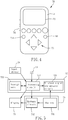
- FIG. 4 illustrates an outer appearance of the remote control device 70
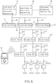
- FIG. 5 illustrates a circuit block diagram of the remote control device 70
- the remote control device 70 comprises a casing 71, a control module 72, a power supply device 73, an input/output connection interface 74, a display 75 and an input device 76 working as an input module.
- the control module 72 and the power supply device 73 are mounted inside the casing 71.
- the control module 72 is electrically coupled with the power supply device 73, the input/output connection interface 74, the display 75 and the input device 76 respectively.
- the input device 76 can be a keyboard, button, microphone or touch control module.
- the touch control module can be assembled with the display 75 to create a touch display for data input and display.
- the power supply device 73 is electrically coupled with the display 75, and comprises a battery 731 and a battery circuit 732 electrically coupled with the battery 731, so as to provide a necessary working power to the remote control device 70.
- the control module 72 controls the hierarchical groups according to the management authority mentioned above, and comprises a processing circuit 721, a storage unit 722 and a wireless signal transmission circuit 723.
- the processing circuit 721 is electrically coupled with the power supply device 73, the storage unit 722, the input device 76, the display 75 and the wireless signal transmission circuit 723 respectively.
- the storage unit 722 is adapted for storing the settings for the slave controllers, including the hierarchical architecture, the identification codes of the slave controllers and the names (identity information) corresponding to the respective identification codes.
- the storage unit 722 further stores information about the management authority.
- the management authority defines a scope that can be controlled by the remote control device 70 under the hierarchical architecture. The scope can refer to the quantity of the hierarchical groups.
- the wireless signal transmission circuit 723 comprises an antenna and a RF circuit for transmitting and receiving RF signals.
- the processing circuit 721 performs a hierarchical management according to the management authority, and generates a control signal in response to an input command (selection signal) from the input device 76.
- the wireless signal transmission circuit 723 is adapted for transmitting and receiving the control signal.
- the hierarchical architecture is the architecture shown in FIG. 1 . Providing different management authorities to different remote control devices 70 enable the remote control devices 70 to perform different power supply managements according to respective defined authorities. In other words, multiple remote control devices with multiple authority scopes can be used for a same hierarchical architecture mentioned above.
- the processing circuit 721 further comprises an identification code generating module for allowing the managing user himself to set identification codes for respective slave controllers and to drive the identification code generation module to randomly generate the identification codes.
- the identification codes are randomly generated by the identification code generation module itself. When the random numbers are up to tens of millions, the identification codes are very difficult to repeat.
- the way to write an identification code to a slave controller is to connect the write-in interface of the slave controller and the input/output connection interface 74 of the remote control device 70 first, and then to enable the processing circuit 721 to write the identification code randomly generated by the identification code generation module into the signal processing circuit of the slave controller.
- the managing user can use the input device 76 of the remote control device 70 to give a name (identity information) to a corresponding slave controller, enabling the slave controller to be defined again.
- the identification code generation module can delete the identification code stored in the signal processing circuit of the slave controller. Therefore, the managing user can install a redefined slave controller in a newly planned hierarchical architecture for power management.
- the core of the control module described in this embodiment is to generate a control signal for wireless control to, based upon the selection signal and settings comprising a hierarchical grouping distribution architecture changeably set by a managing user and respective corresponding identification codes of the slave controllers set by the managing user, manage the operations of slave controllers with a capability of doing a group controlling under the hierarchical architecture.
- This core of the control module can also be implemented by incorporating a software of doing such a core into a general hardware.
- the identification code is written into the slave controller through the remote control device 70, but the identification code may be written to the slave controller through another device, for example, by the computer after it is set thereby. Therefore, writing the identification code is not limited to be done by the remote control device, and the writing can be achieved by a wireless manner.
- the hierarchical architecture setting of the slave controllers may also be inputted by a computer, a mobile phone or a PDA, etc., and the finished settings of the hierarchical architecture of the slave controllers can be transmitted to the remote control device through the input/output connection interface 74 and be stored in the storage unit of the remote control device. Therefore, the setting of the hierarchical architecture of the slave controllers is not limited to be done by means of the remote control device.
- the input/output connection interface 74 can transmit an identification code to a corresponding slave controller without knowing the identity information of the slave controller first, and can be used to input the settings and identifying information, such as names or model numbers, of the slave controllers that are set by the user
- the measure to transmit data to the remote control device through the input/output connection interface 74 can be achieved by a wired manner or a wireless manner, and this is a known technology, and thus is not described in details..
- the remote control management method comprises the steps outlined hereinafter.
- installation locations or functions of slave controllers 60-61214 are input so as to establish a hierarchical architecture thereof.
- the hierarchical architecture defines the relationship of the slave controllers in the hierarchical architecture.
- Fig. 6 also shows a representative slave controller for each group in an end level.
- the managing user defines each slave controller.
- the managing user conducts a setting of an identification code for each slave controller.
- the managing user can use the above-described method to randomly generate respective identification codes for respective slave controllers, and can define corresponding names (definitions) for respective slave controllers using the remote control device 70 so as to complete and store the settings of the slave controllers (i.e., storing the name, identification code and corresponding hierarchical group for each slave controller). Thereafter, a number of selected controls are output by the remote control device 70.
- the operations of the slave controllers 60-61214 are thus controlled in accordance with the hierarchical architecture and the identification codes for respective slave controllers.
- user uses the remote control device 70 to control the power supply or operation status of a hierarchical group or a slave controller.
- each of the slave controllers can be increased or decreased by means of the remote control device itself or an external computer.
- the core of the remote control management method comprises a receiving step for receiving a selection signal, and a control step for generating a control signal for wireless control to, based upon the selection signal and settings comprising a hierarchical grouping distribution architecture changeably set by a managing user and respective corresponding identification codes of the slave controllers set by the managing user, manage the operations of slave controllers with a capability of doing a group controlling under the hierarchical architecture.
- the remote control device 70 can work under a certain management authority.
- a remote control device 70 having a highest management authority may manage all of the slave controllers.
- a remote control device 70 having a middle management authority can control the slave controllers in hierarchical groups 11, 12, and 13. That is, a remote control device 70 having an authority to hierarchical group 12 may control the slave controllers 61-61214, but not the slave controllers 60 and 62.
- the management authority of a remote control device can be limited to a hierarchical group of one floor or a relatively smaller group. The scope of the management authority is not limited to that described in this embodiment. In other words, for a group that is not authorized to a remote control device, the remote control device cannot control such a group.
- each management authority setting can be set to be effective for a specific period of time.
- all of the slave controllers 60-61214 are connected with power lines 90 and allocated at a front side of respective hierarchical groups 11-12214 for controlling the power supply to respective hierarchical groups 11-12214.
- the remote control device 70 emits a control signal having an identification code corresponding to slave controller 61211, and the wireless signal receiver circuit of the slave controllers within an effective control range of the remote control device 70 will receive the control signal having the identification code.
- the signal processing circuit of the slave controller 61211 will cut off the power supply to the hierarchical group 12211 according to the control signal. All the sockets in this hierarchical group 12211 are turned off, and other slave controllers remain unchanged.
- the present invention also provides a local switching control function for a direct local control.
- the input device 76 of the remote control device 70 further comprises a local ON/OFF button 761.
- the local control signal of the remote control device 70 will be sent to all slave controllers within a selected hierarchical group.
- the transmission power of this local control signal is lower than that of a normal control signal for controlling a specifically selected slave controller.
- This local control signal is effective only to a slave controller, preferred within a selected hierarchical group, within the room #201 1221 of second floor 122.
- the remote control device 70 can directly control a specific slave controller near or adjacent to the remote control device 70 without through a selection to the specific slave controller adjacent thereto.
- a switching state of the slave controller 61211 near the remote control device 70 can be controlled.
- the distance for the so-call "near or adjacent" could be 1-3 meters. However, this distance is not limited to the distance illustrated in this embodiment.
- the number of slave controllers to be effectively controlled is determined subject to the actual effective distance of the wireless local control signal and the selected hierarchical group.
- the control signal of the remote control device 70 is preferably a RF signal.
- RF signals have better penetration and can travel far distances, so they can cover a larger space.
- the wireless control according to this embodiment of the present invention needs not to be established on a network architecture, its implementation is relatively simple and direct and will not be hacked.
- the identification code according to this embodiment of the present invention is randomly generated by the control device in a random manner. It may provide millions of different random codes. Therefore, this method is advantageous for slave controllers that require a safety consideration.
- the slave controller uses an identification code randomly provided by a managing user through a remote control device, without a need to preset such an identification code during manufacturing.
- the wireless hierarchical power management system of the present invention is more flexible, easy to be expanded than the conventional designs, and can reduce the probability of duplicate identification codes.
- the managing user can limit the scope of the authorized management in a certain remote control device subject to the setting of the authority in the remote control device. The user can use the remote control device to execute hierarchical group power control, and the problem in convention designs that needs to find the switch corresponding to the appliance to be controlled is resolved, and the use of power lines is reduced.
Landscapes
- Engineering & Computer Science (AREA)
- Automation & Control Theory (AREA)
- Computer Networks & Wireless Communication (AREA)
- Signal Processing (AREA)
- Human Computer Interaction (AREA)
- Physics & Mathematics (AREA)
- General Physics & Mathematics (AREA)
- Power Engineering (AREA)
- Selective Calling Equipment (AREA)
- Telephonic Communication Services (AREA)
Description
- The present invention relates to a power management technology and more particularly to a hierarchical wireless power management system and method, as well as a remote control device and a slave controller used therein.
- In a conventional arrangement, a power line wiring in a house must consider positions of power switches so as to provide a convenient operation to a user, and most of the power switches are configured to a control matching of one to one or multiple to one for respective appliances. For example, for the lighting in a house, a power switch is used to control a lamp or a number of lamps. Sometimes, multiple power switches are also used to control one or more lamps. However, the wiring for this kind of control matching not only needs to fulfill a distance of the power line to the lamp, but also needs to fulfill a distance from the lamp to the power switch. Moreover, once the wiring was completed, it is not easy to change the positions of the power switches or sockets, which in turn results in an inconvenient situation.
- Furthermore, most of the factories or commercial buildings are spacious, and the power switches are scattered over many places. Sometimes, for a new managing person, it is not easy to find all of the power switches, and thus results in a problem to manage power.
- Currently, there are some power management methods that allow managers to manage power connections in a configuration of a host and its network-connected slave controllers by means of hand-held devices. In this kind of management methods, a machine code or identification code of a slave controller is set during manufacturing in factory, and the identification code cannot be arbitrarily changed by the users. This kind of management methods thus have a problem that the scope of applying remote control is not easy to be expanded, and a multi-level management is not able to be achieved. Moreover, the signal transmission by means of network may be not worktable when the network connection fails, the way through network is thus easy to become an unstable factor for power management.
- There is also a kind of control system using a location-based address commissioned by a user to control lighting devices in group, such as
US 2015/0028998 . In this patent, a lighting device is commissioned by the user with at least one LD based upon its location distribution and its intended group. However, in such a manner, the user needs to consider a name and/or ID given for respective locations; it is very likely that the commissioned addresses in two environments are duplicated. Moreover, due to a fact that the identification code for each lighting device is in a form relevant to location hierarchies of the slave controllers in a hierarchical architecture, the number of digits for respective LBA/LDs will change per different number of location hierarchies set by different users. It will result of a difficulty of signal receiving and recognition for a circuit system. Furthermore, when the user is planning a hierarchical group of the lighting devices based upon locations, it also need to contemplate or identify an ID for each location or group and thus is not convenient. - The present invention has been accomplished under the circumstances in view of the aforesaid. It is a main object of the present invention to provide a hierarchical wireless power management system and method as disclosed in the appended claims, which can be performed without through a network, omitting the conventional power switches and reducing the use of power lines.
- To achieve this and other objects of the present invention, a remote control device is provided as as claimed in independent claim 1.
- To achieve this and other objects of the present invention, the present invention also provides a slave controller as claimed in
independent claim 10. - To achieve this and other objects of the present invention, the present invention also provides a hierarchical wireless power management system, as claimed in
claim 13, which comprises the above-described remote control device and slave controllers. - To achieve this and other objects of the present invention, the present invention also provides a remote control management method as claimed in independent claim 14.
- Thus, the managing user can freely and flexibly increase or reduce the number of hierarchical groups without worrying about the wiring configuration of the power lines, and can also control the slave controllers individually or in a hierarchical group. Moreover, the managing user needs not to remember or edit the identification codes of the slave controllers. The system itself can randomly generate the identification codes. Through the remote control device, the managing user can intuitively and easily controls the power supply status of each group of slave controllers or appliances, and the wireless control can be achieved without through the internet.
- Other advantages and features of the present invention will be fully understood by reference to the following specification in conjunction with the accompanying drawings, in which like reference signs denote like components of structure.
-
-
FIG. 1 illustrates an exemplary hierarchical architecture of salve controllers adapted for appliances in a school in accordance with the present invention. -
FIG. 2 illustrates the outer appearance of a slave controller in accordance with the present invention. -
FIG. 3 is a circuit block diagram of the slave controller in accordance with the present invention. -
FIG. 4 illustrates the outer appearance of a remote control device in accordance with the present invention. -
FIG. 5 is a circuit block diagram of the remote control device in accordance with the present invention. -
FIG. 6 is a schematic view of applying a hierarchical wireless power management system in accordance with the present invention. - The constituent elements of the hierarchical wireless power management system of the present invention and the effects of the present invention will now be described with reference to the annexed drawings, wherein the components, the size and the appearance of the hierarchical wireless power management system are only intended to illustrate the technical features of the present invention and are not intended to limit the present invention.
- The hierarchical wireless power management system does not achieve power management through a network such as power network, communication network, wireless network (WiFi) or local area network. The hierarchical architecture of the slave controllers used in the present invention is free to be increased and decreased in size of a hierarchical group and is not constrained by the locations of indoor switches and sockets. The number of the power lines can be reduced.
- The hierarchical wireless power management system can be used to control the power supply to many kinds of electrical appliances, such as sockets, electronic locks, motor switches, lamps, loudspeakers, air conditioners, electric fans, electronic gates and audio and video equipments etc. in a school, shopping mall, sports field, factory or home. The "control" means the operation of turning on/off the power supply, or regulating the rate of the power supply to the electrical appliance. The motor switch may be used to control the forward and reverse rotation of a motor, in particular a motor used for rolling a roll-up door or an electric curtain.
- Taking school as an example, the hierarchical architecture used in the present invention is illustrated in
FIG. 1 . In this example, the area to be applied for the hierarchical architecture is a school, the power supply for all electrical appliances in the school is classified with the hierarchical architecture, and the hierarchical architecture may include a plurality of hierarchical groups. For example, a number of departments are defined as the highest hierarchical groups, referenced by 10, 20, and 30. A number of buildings in onedepartment 10 are defined as secondary highest hierarchical groups, referenced by 11, 12, and 13. A number of floors in onebuilding 12 are defined as middle-level hierarchical groups, referenced by 121, 122, and 123. A number of classrooms or spaces in onefloor 122 are defined as smaller-level hierarchical groups, referenced by 1221, 1222, and 1223. At final, a number of spatial divisions in oneclassroom 1221 can be defined as smallest-level-level hierarchical groups, referenced by 12211, 12212, 12213, and 12214 and so on. - The hierarchical groups that are not expanded in
FIG. 1 can be classified or defined into multiple hierarchical groups of different levels. The hierarchical group planning described above is not a limitation. In this embodiment, the hierarchical groups are illustrated as relating to power supply in the area.. The groups in the area can also be a number of electrical appliances or a same type of electrical appliances. For example, the smallest-levelhierarchical group 12211 comprises multiple electrical sockets; the smallest-levelhierarchical groups hierarchical group 12214 comprises multiple electrical fans; and the smaller-levelhierarchical group 1221 comprises all the electrical appliances of the smallest-level hierarchical groups 12211-12214. That is, the power supply to the smallest-level hierarchical groups 12211-12214 can be controlled through controlling the power supply to the smaller-levelhierarchical group 1221. - The hierarchical wireless power management system comprises a plurality of
slave controllers 50 and aremote control device 70. Theseslave controllers 50 are respectively electrically connected with the individual electrical appliances (not shown) in the aforesaid hierarchical groups of the hierarchical architecture for controlling the operation of the respective electrical appliances, including switching or action. The settings of the hierarchical groups of the hierarchical architecture are determined according to the installation locations or functions of theslave controllers 50. Everyindividual slave controller 50 can appear in different hierarchical groups to achieve different control purposes or needs. The application and connection of theslave controllers 50 will be explained later. Theremote control device 70 is adapted for generating a wireless control signal for controlling oneslave controller 50 or a number of theslave controllers 50, driving theslave controller 50 or themultiple slave controllers 50 to regular its or their power output ratio and action. - The
remote control device 70 allows the managing user to do settings related to the hierarchical architecture of the slave controllers by means of theremote control device 70 itself and to store the settings, and can also receive and store hierarchical architecture settings that were made by the managing user from an external device. These settings related to the hierarchical architecture can, for example, comprise definitions of the appliances associated to these slave controllers, corresponding identification codes thereof, and allocated hierarchical groups in the hierarchical architecture. The definitions of the slave controllers can be the names or model codes of the appliances connected to respective slave controllers that the user can intuitively identify. The settings of the hierarchical architecture can also include a setting for management authority. The remote control device can be used for doing an authorized management to the hierarchical groups in the hierarchical architecture that are authorized to be managed according to the management authority setting. Furthermore, the authority of one hierarchical group in the hierarchical architecture is preferred to include authorities to subgroups in such a hierarchical group. - The
remote control device 70 controls the switching or action state of theslave controllers 50 under a hierarchical architecture mode according to the settings of the hierarchical architecture related to the slave controllers, and can do a hierarchical group control according to the hierarchical architecture. For example, theremote control device 70 can control theslave controller 50 to do a turn ON or OFF action by means of a control signal. Furthermore, theremote control device 70 can also execute a local ON/OFF control to directly control anadjacent slave controller 50 without a selection on thenearby slave controller 50. Under this function, the transmission power of such a control signal from theremote control device 70 is lower than the transmission power of a general control signal for controlling one particular selected slave controller. This function can also be set to be only applicable to the slave controllers in one selected or particular hierarchical group of the hierarchical architecture. - Referring to
FIG. 2 and FIG. 3, FIG. 2 illustrates the outer appearance of theslave controller 50 andFIG. 3 illustrates the circuit block diagram of theslave controller 50. As illustrated, theslave controller 50 comprises ahousing 51, apower input connector 52, apower output connector 53, a write-in interface 54, and anoperating unit 55. The operatingunit 55 is mounted inside thehousing 51. Thepower input connector 52, thepower output connector 53 and the write-in interface 54 are respectively electrically connected to the operatingunit 55. Thepower input connector 52 is for connection to a power cable. Thepower output connector 53 is adapted for connection to a power input terminal of an electrical appliance. - The operating
unit 55 comprises apower circuit 551, asignal processing circuit 552, aswitching circuit 553 and a wirelesssignal receiver circuit 554. Thepower circuit 551 is electrically coupled with thepower input connector 52 and thesignal processing circuit 552. Theswitching circuit 553 connects thesignal processing circuit 552, thepower input connector 52 and thepower output connector 53. The wirelesssignal receiver circuit 554 is electrically connected to thesignal processing circuit 552, and adapted for receiving a control signal having a corresponding identification code. - The
signal processing circuit 552 controls the operation of theswitching circuit 553 according to the control signal, thereby controlling the ratio of the power in the power cable output to thepower output connector 53, or causing the switching circuit to generate an output for an action of the appliance. The ratio of the power output includes non power output, full power output, or a specific percentage of power output. The specific percentage of power output can be controlled by means of phase control or other known method. Since the control method is of the known art, its detailed description is omitted hereby. - The
signal processing circuit 552 is electrically coupled with the write-in interface 54, and can store an identification code that is randomly set by the managing user and received through the write-in interface. The identification code stored in thesignal processing circuit 552 can be deleted, and a new identification code can be written into thesignal processing circuit 552 through the write-in interface 54. Furthermore, in this embodiment, theslave controller 50 does not need to send out its identity information before receiving the assigned identification code, and the randomly set identification code can be immediately transmitted to theslave controller 50 in the initial stage. - Referring to
FIGS. 4 and 5, FIG. 4 illustrates an outer appearance of theremote control device 70 andFIG. 5 illustrates a circuit block diagram of theremote control device 70. Theremote control device 70 comprises acasing 71, acontrol module 72, apower supply device 73, an input/output connection interface 74, adisplay 75 and aninput device 76 working as an input module. Thecontrol module 72 and thepower supply device 73 are mounted inside thecasing 71. Thecontrol module 72 is electrically coupled with thepower supply device 73, the input/output connection interface 74, thedisplay 75 and theinput device 76 respectively. Theinput device 76 can be a keyboard, button, microphone or touch control module. The touch control module can be assembled with thedisplay 75 to create a touch display for data input and display. - The
power supply device 73 is electrically coupled with thedisplay 75, and comprises abattery 731 and abattery circuit 732 electrically coupled with thebattery 731, so as to provide a necessary working power to theremote control device 70. - The
control module 72 controls the hierarchical groups according to the management authority mentioned above, and comprises aprocessing circuit 721, astorage unit 722 and a wirelesssignal transmission circuit 723. Theprocessing circuit 721 is electrically coupled with thepower supply device 73, thestorage unit 722, theinput device 76, thedisplay 75 and the wirelesssignal transmission circuit 723 respectively. Thestorage unit 722 is adapted for storing the settings for the slave controllers, including the hierarchical architecture, the identification codes of the slave controllers and the names (identity information) corresponding to the respective identification codes. Thestorage unit 722 further stores information about the management authority. The management authority defines a scope that can be controlled by theremote control device 70 under the hierarchical architecture. The scope can refer to the quantity of the hierarchical groups. The wirelesssignal transmission circuit 723 comprises an antenna and a RF circuit for transmitting and receiving RF signals. - The
processing circuit 721 performs a hierarchical management according to the management authority, and generates a control signal in response to an input command (selection signal) from theinput device 76. The wirelesssignal transmission circuit 723 is adapted for transmitting and receiving the control signal. The hierarchical architecture is the architecture shown inFIG. 1 . Providing different management authorities to differentremote control devices 70 enable theremote control devices 70 to perform different power supply managements according to respective defined authorities. In other words, multiple remote control devices with multiple authority scopes can be used for a same hierarchical architecture mentioned above. - The
processing circuit 721 further comprises an identification code generating module for allowing the managing user himself to set identification codes for respective slave controllers and to drive the identification code generation module to randomly generate the identification codes. The identification codes are randomly generated by the identification code generation module itself. When the random numbers are up to tens of millions, the identification codes are very difficult to repeat. In this embodiment, the way to write an identification code to a slave controller is to connect the write-in interface of the slave controller and the input/output connection interface 74 of theremote control device 70 first, and then to enable theprocessing circuit 721 to write the identification code randomly generated by the identification code generation module into the signal processing circuit of the slave controller. Furthermore, the managing user can use theinput device 76 of theremote control device 70 to give a name (identity information) to a corresponding slave controller, enabling the slave controller to be defined again. - Similarly, the identification code generation module can delete the identification code stored in the signal processing circuit of the slave controller. Therefore, the managing user can install a redefined slave controller in a newly planned hierarchical architecture for power management. In general, one skilled in the art could understand that the core of the control module described in this embodiment is to generate a control signal for wireless control to, based upon the selection signal and settings comprising a hierarchical grouping distribution architecture changeably set by a managing user and respective corresponding identification codes of the slave controllers set by the managing user, manage the operations of slave controllers with a capability of doing a group controlling under the hierarchical architecture. This core of the control module can also be implemented by incorporating a software of doing such a core into a general hardware.
- Although, in this embodiment, the identification code is written into the slave controller through the
remote control device 70, but the identification code may be written to the slave controller through another device, for example, by the computer after it is set thereby. Therefore, writing the identification code is not limited to be done by the remote control device, and the writing can be achieved by a wireless manner. The hierarchical architecture setting of the slave controllers may also be inputted by a computer, a mobile phone or a PDA, etc., and the finished settings of the hierarchical architecture of the slave controllers can be transmitted to the remote control device through the input/output connection interface 74 and be stored in the storage unit of the remote control device. Therefore, the setting of the hierarchical architecture of the slave controllers is not limited to be done by means of the remote control device. Therefore, whenever a name of a slave controller is to be input, managing user only needs to enter the name of the slave controller without arranging or knowing its ID. The user thus can intuitively change the name of the slave controller. In other words, the input/output connection interface 74 can transmit an identification code to a corresponding slave controller without knowing the identity information of the slave controller first, and can be used to input the settings and identifying information, such as names or model numbers, of the slave controllers that are set by the user The measure to transmit data to the remote control device through the input/output connection interface 74 can be achieved by a wired manner or a wireless manner, and this is a known technology, and thus is not described in details.. - Referring to
FIG. 6 , the remote control management method according to one embodiment, which is not part of the invention as claimed but it is useful for understanding the invention, comprises the steps outlined hereinafter. At first, installation locations or functions of slave controllers 60-61214 are input so as to establish a hierarchical architecture thereof. The hierarchical architecture defines the relationship of the slave controllers in the hierarchical architecture.Fig. 6 also shows a representative slave controller for each group in an end level. In this step, the managing user defines each slave controller. Thereafter, the managing user conducts a setting of an identification code for each slave controller. In this step, the managing user can use the above-described method to randomly generate respective identification codes for respective slave controllers, and can define corresponding names (definitions) for respective slave controllers using theremote control device 70 so as to complete and store the settings of the slave controllers (i.e., storing the name, identification code and corresponding hierarchical group for each slave controller). Thereafter, a number of selected controls are output by theremote control device 70. The operations of the slave controllers 60-61214 are thus controlled in accordance with the hierarchical architecture and the identification codes for respective slave controllers. In this step, user uses theremote control device 70 to control the power supply or operation status of a hierarchical group or a slave controller. - Therefore, each of the slave controllers can be increased or decreased by means of the remote control device itself or an external computer. In conclusion, the core of the remote control management method comprises a receiving step for receiving a selection signal, and a control step for generating a control signal for wireless control to, based upon the selection signal and settings comprising a hierarchical grouping distribution architecture changeably set by a managing user and respective corresponding identification codes of the slave controllers set by the managing user, manage the operations of slave controllers with a capability of doing a group controlling under the hierarchical architecture.
- Furthermore, the
remote control device 70 can work under a certain management authority. For example, aremote control device 70 having a highest management authority may manage all of the slave controllers. Aremote control device 70 having a middle management authority can control the slave controllers inhierarchical groups remote control device 70 having an authority tohierarchical group 12 may control the slave controllers 61-61214, but not theslave controllers - In
FIG. 6 , all of the slave controllers 60-61214 are connected withpower lines 90 and allocated at a front side of respective hierarchical groups 11-12214 for controlling the power supply to respective hierarchical groups 11-12214. For example, when the user uses the input device of theremote control device 70 to switch off the power supply to thehierarchical group 12211, theremote control device 70 emits a control signal having an identification code corresponding toslave controller 61211, and the wireless signal receiver circuit of the slave controllers within an effective control range of theremote control device 70 will receive the control signal having the identification code. However, only the signal processing circuit of theslave controller 61211 will cut off the power supply to thehierarchical group 12211 according to the control signal. All the sockets in thishierarchical group 12211 are turned off, and other slave controllers remain unchanged. - Furthermore, the present invention also provides a local switching control function for a direct local control. As illustrated in
FIG. 4 , theinput device 76 of theremote control device 70 further comprises a local ON/OFF button 761. In this embodiment, when theremote control device 70 is put in a place inroom # 201 1221 ofsecond floor 122, and a local ON/OFF button in theremote control device 70 is pushed to do a local switching control function, the local control signal of theremote control device 70 will be sent to all slave controllers within a selected hierarchical group. However, the transmission power of this local control signal is lower than that of a normal control signal for controlling a specifically selected slave controller. This local control signal is effective only to a slave controller, preferred within a selected hierarchical group, within theroom # 201 1221 ofsecond floor 122. In this situation, theremote control device 70 can directly control a specific slave controller near or adjacent to theremote control device 70 without through a selection to the specific slave controller adjacent thereto. For example, a switching state of theslave controller 61211 near theremote control device 70 can be controlled. In this embodiment, the distance for the so-call "near or adjacent" could be 1-3 meters. However, this distance is not limited to the distance illustrated in this embodiment. Furthermore, the number of slave controllers to be effectively controlled is determined subject to the actual effective distance of the wireless local control signal and the selected hierarchical group. Of course, as a variant example, it is also possible to effect a control to a slave controller by means of distance condition only regardless a selection to a hierarchical group. In this case, the effective range of the local control signal for this local switching control function must be properly adjusted. - In this embodiment, the control signal of the
remote control device 70 is preferably a RF signal. RF signals have better penetration and can travel far distances, so they can cover a larger space. Furthermore, the wireless control according to this embodiment of the present invention needs not to be established on a network architecture, its implementation is relatively simple and direct and will not be hacked. In particular, the identification code according to this embodiment of the present invention is randomly generated by the control device in a random manner. It may provide millions of different random codes. Therefore, this method is advantageous for slave controllers that require a safety consideration. - In view of the above, the slave controller uses an identification code randomly provided by a managing user through a remote control device, without a need to preset such an identification code during manufacturing. Thus, the wireless hierarchical power management system of the present invention is more flexible, easy to be expanded than the conventional designs, and can reduce the probability of duplicate identification codes. Moreover, the managing user can limit the scope of the authorized management in a certain remote control device subject to the setting of the authority in the remote control device. The user can use the remote control device to execute hierarchical group power control, and the problem in convention designs that needs to find the switch corresponding to the appliance to be controlled is resolved, and the use of power lines is reduced.
- Although a particular embodiment of the present invention has been described in detail for purposes of illustration, various modifications and enhancements may be made without departing from the scope of the invention. Accordingly, the invention is not to be limited except as by the appended claims.
Claims (14)
- A remote control device (70) for controlling a plurality of slave controllers (50, 60-61214), said remote control device (70) comprising an input module (76) for receiving a selection signal resulted from a selection to at least one selected slave controller on settings that are stored in the remote control device (70), related to the plurality of slave controllers (50, 60-61214), and have identification codes corresponding to the slave controllers; and
a control module (72) for generating a control signal containing at least one identification code for the at least one selected slave controller (50, 60-61214) to wirelessly control operations of the at least one selected slave controller based upon the selection signal and the settings, and being characterized in that:the settings comprise a hierarchical grouping architecture consisting of a plurality of hierarchical groups (10, 20, 30, 12, 122, 1221) defined by a managing user for controlling the slave controllers (50, 60-61214), and respective corresponding identification codes for the plurality of the slave controllers (50, 60-61214) each being a random number that is automatically set by following a setting of a slave controller (50, 60-61214) and is able to be identified for at least one of the slave controllers (50, 60-61214),wherein the hierarchical grouping architecture defines the relationship of the slave controllers (50, 60-61214) in the hierarchical groups, and is changeably set by the managing user and the respective corresponding identification codes of the slave controllers (50, 60-61214) are set by the managing user, and thus the operations of the slave controllers (50, 60-61214) are controlled in accordance with the hierarchical grouping architecture and the identification codes for respective slave controllers (50, 60-61214),wherein the identification codes are randomly generated by an identification code generation module of the control module (72), which allows the managing user himself to set the identification codes for respective slave controllers (50, 60-61214),wherein the control module (72) is adapted to manage the operations of the slave controllers (50, 60-61214) with a capability of doing a group controlling under the hierarchical grouping architecture. - The remote control device (70) as claimed in claim 1, further comprising:a display (75) electrically coupled to said control module (72) for displaying a selection; anda power supply device (73) coupled to said control module (72) and said display (75), said control module (72) comprising a processing circuit (721), a wireless signal transmission circuit (723) and a storage unit (722), said wireless signal transmission circuit (723) being coupled to said processing circuit (721) and adapted for transmitting said control signal to a corresponding slave controller (50, 60-61214) according to the selection signal, said storage unit (722) being coupled to said processing circuit (721) for storing the settings related to the slave controllers (50, 60-61214).
- The remote control device (70) as claimed in claim 1, wherein said identification codes are used to control respective slave controller (60-61214) or a hierarchical group (10, 20, 30, 12, 122, 1221) to which the slave controllers (60-61214) belong in the hierarchical grouping architecture.
- The remote control device (70) as claimed in claim 3, wherein said control module (72) comprises the identification code generation module for randomly generating said identification codes of said slave controllers (50, 60-61214) to be set into the settings and written into said slave controllers (50, 60-61214) correspondingly after finishing the settings of said hierarchical grouping architecture.
- The remote control device (70) as claimed in claim 1, wherein the settings of said slave controllers (50, 60-61214) include a hierarchical management authority for allowing said control module (72) to manage certain hierarchical groups in said hierarchical grouping architecture according to the hierarchical management authority.
- The remote control device (70) as claimed in claim 1, further comprising an input/output connection interface (74) adapted for setting a control relationship with the slave controllers initially by means of transmitting the identification codes to the slave controllers (50, 60-61214).
- The remote control device (70) as claimed in claim 1, wherein said control module (72) further comprises a local switching control function for directly controlling a slave controller (50, 60-61214) near to the remote control device (70) using a control signal activated by a local button (761) without a need to select the slave controller.
- The remote control device (70) as claimed in claim 7, wherein a transmission power of the control signal of said remote control device (70) in said local switching control function is lower than that of a control signal for controlling a specifically selected slave controller (50, 60-61214).
- The remote control device (70) as claimed in claim 7, wherein said local switching control function is limited to the slave controllers (50, 60-61214) in one specific hierarchical group (12, 122, 1221) of said hierarchical grouping architecture.
- A slave controller (50, 60-61214) comprising:a power input connector (52); a write-in interface (54) for allowing a managing user to input an identification code for the slave controller (50, 60-61214); and an operating unit (55) connecting said power input connector (52) and said write-in interface (54), said operating unit (55) comprising a signal processing circuit (552), a switching circuit (553) and a wireless signal receiver circuit (554), said signal processing circuit (552) being adapted for storing said identification code, said switching circuit (553) connecting said signal processing circuit (552) and said power input connector (52), said wireless signal receiver circuit (554) being adapted for receiving a control signal corresponding to said identification code and electrically connected to said signal processing circuit (552), said signal processing circuit (552) being adapted for regulating the operation of said switching circuit (553) and doing an output according to said control signal, being characterized in thatthe identification code is a random number that is set automatically by following a setting of the slave controller (50, 60-61214) in a hierarchical grouping architecture defined by a managing user for controlling the slave controller (50, 60-61214) and is able to be identified for the slave controller (50, 60-61214),wherein the identification code is randomly generated by an identification code generation module of a control module (72) comprised in a remote control device (70), which allows the managing user himself to set the identification code for the slave controller (50, 60-61214),wherein the control module (72) is adapted to manage the operation of the slave controller (50, 60-61214) with a capability of doing a group controlling under a hierarchical grouping architecture,wherein the hierarchical grouping architecture defines the relationship of slave controllers (50, 60-61214) in the hierarchical groups, and is changeably set by the managing user and the respective corresponding identification codes of the slave controllers (50, 60-61214) are set by the managing user.
- The slave controller (50, 60-61214) as claimed in claim 10, wherein the identification code is inputted to the slave controller (50, 60-61214) under a control of the managing user and the corresponding slave controller (50, 60-61214) does not need to send out its identity information before receiving the assigned identification code.
- The slave controller (50, 60-61214) as claimed in claim 10, wherein said identification code is used to control respective slave controller (60-61214) and a hierarchical group (10, 20, 30, 12, 122, 1221) to which the slave controller belongs in the hierarchical grouping architecture.
- A hierarchical wireless power management system, comprising:a plurality of remote control devices (70) as claimed in any of claims 1-9; anda plurality of slave controllers (50, 60-61214) as claimed in any of claims 10-12 and being characterized in thatthe authorities of the remote control devices comprise a highest management authority and a middle management authority of the hierarchical architecture, so as to limit the management of a remote control device with middle management authority to the slave controllers of the authorized hierarchical groups in the hierarchical architecture,wherein a remote control device having the highest management authority is provided to manage all of the slave controllers, and a remote control device having the middle management authority is limited to a hierarchical group and cannot control another hierarchical group for which it is not authorized.
- A remote control management method for managing the operation of a plurality of slave controllers (50, 60-61214), the remote control management method comprising:a receiving step for receiving a selection signal resulted from a selection to at least one selected slave controller on settings that are stored in a remote control device (70), related to the plurality of slave controllers (50, 60-61214), and have identification codes corresponding to the slave controllers; anda control step for generating a control signal containing at least one identification code for at least one selected slave controller to wirelessly control operations of the at least one selected slave controller, based upon the selection signal and the settings, and being characterized in thatthe settings comprise a hierarchical grouping architecture consisting of a plurality of hierarchical groups (10, 20, 30, 12, 122, 1221) defined by a managing user for controlling the slave controllers (50, 60-61214), and respective corresponding identification codes for the plurality of the slave controllers (50, 60-61214) each Lilting being a random number that is automatically set by following a setting of a slave controller (50, 60-61214) and is able to be identified for at least one of the slave controllers (50, 60-61214),wherein the hierarchical grouping architecture defines the relationship of the slave controllers (50, 60-61214) in the hierarchical groups, and is changeably set by the managing user and the respective corresponding identification codes of the slave controllers (50, 60-61214) are set by the managing user, and thus the operations of the slave controllers (50, 60-61214) are controlled in accordance with the hierarchical grouping architecture and the identification codes for respective slave controllers (50, 60-61214),wherein the identification codes are randomly generated by an identification code generation module of the remote control device (70), which allows the managing user himself to set the identification codes for respective slave controllers (50, 60-61214),wherein the remote control device (70) manages the operations of the slave controllers (50, 60-61214) with a capability of doing a group controlling under the hierarchical grouping architecture.
Applications Claiming Priority (2)
| Application Number | Priority Date | Filing Date | Title |
|---|---|---|---|
| TW106116768 | 2017-05-19 | ||
| TW106128311A TWI634399B (en) | 2017-05-19 | 2017-08-21 | Wireless layer power management system and remote control device thereof, controlled device and remote control method |
Publications (2)
| Publication Number | Publication Date |
|---|---|
| EP3404870A1 EP3404870A1 (en) | 2018-11-21 |
| EP3404870B1 true EP3404870B1 (en) | 2022-01-12 |
Family
ID=64452688
Family Applications (1)
| Application Number | Title | Priority Date | Filing Date |
|---|---|---|---|
| EP17197938.8A Active EP3404870B1 (en) | 2017-05-19 | 2017-10-24 | Hierarchical wireless power management system and method, as well as remote control device and slave controller used therein |
Country Status (4)
| Country | Link |
|---|---|
| EP (1) | EP3404870B1 (en) |
| JP (1) | JP6678696B2 (en) |
| ES (1) | ES2907955T3 (en) |
| TW (1) | TWI634399B (en) |
Families Citing this family (1)
| Publication number | Priority date | Publication date | Assignee | Title |
|---|---|---|---|---|
| CN110166262B (en) * | 2019-05-16 | 2021-08-13 | 深圳数联天下智能科技有限公司 | Group management method, device, system, computer device and readable storage medium |
Family Cites Families (18)
| Publication number | Priority date | Publication date | Assignee | Title |
|---|---|---|---|---|
| CN1186595C (en) * | 2000-08-01 | 2005-01-26 | 贵州以太科技信息产业有限责任公司 | Universal intelligent monitor |
| JP2002185628A (en) * | 2000-12-18 | 2002-06-28 | Hitachi Ltd | Wireless power management system and remote control transmitter |
| US6868310B2 (en) * | 2001-04-06 | 2005-03-15 | Eni Technology, Inc. | Predictive failure scheme for industrial thin films processing power delivery system |
| US7889051B1 (en) * | 2003-09-05 | 2011-02-15 | The Watt Stopper Inc | Location-based addressing lighting and environmental control system, device and method |
| JP4715300B2 (en) * | 2005-05-20 | 2011-07-06 | 日本電気株式会社 | Remote control system and method, remote control device, and control target device |
| CN101218787B (en) * | 2005-07-04 | 2012-08-29 | Vkr控股公司 | System for operating a plurality of devices including master unit and a plurality of slave units |
| JP2009536778A (en) * | 2006-05-11 | 2009-10-15 | コーニンクレッカ フィリップス エレクトロニクス エヌ ヴィ | Lighting system having a group of linked lights |
| TWM348951U (en) * | 2008-07-24 | 2009-01-11 | Josephtec Co Ltd | Bidirectional wireless transmittable receptacle-type wattmeter and power-consumption information display remote controller |
| JP2011182183A (en) * | 2010-03-01 | 2011-09-15 | Panasonic Corp | Device information display apparatus, television, equipment information display method, program, and recording medium |
| CN102594574A (en) * | 2011-01-04 | 2012-07-18 | 台达电子工业股份有限公司 | Power distribution unit and power management architecture applicable to same |
| CN102735955B (en) * | 2011-04-15 | 2015-02-04 | 财团法人交大思源基金会 | Power monitoring device and power monitoring method for identifying electrical appliance status |
| TW201327498A (en) * | 2011-12-29 | 2013-07-01 | Amtran Technology Co Ltd | Method for controlling grouped devices |
| TWM435736U (en) * | 2012-01-09 | 2012-08-11 | yuan-xi Ding | Intelligent power with wireless identification and device |
| US9077929B2 (en) * | 2012-09-13 | 2015-07-07 | Asia Vital Components Co., Ltd. | Portable electronic device based user-definable remote-control interface system and operating method thereof with a display and input unit adapted to show an interface allocation information map, the map being divided into a plurality of sub-areas |
| CN203191728U (en) * | 2013-04-17 | 2013-09-11 | 赖丽纯 | Power Outlet Control |
| TWI527403B (en) * | 2014-04-24 | 2016-03-21 | 全漢企業股份有限公司 | Master-slave control system and its addressing method |
| TWI511616B (en) * | 2014-05-13 | 2015-12-01 | 索玉昇 | Control system and control method based on synchronous AC power frequency |
| CN105657073B (en) * | 2016-04-01 | 2019-07-23 | 上海赋锦信息技术有限公司 | A kind of smart home system |
-
2017
- 2017-08-21 TW TW106128311A patent/TWI634399B/en active
- 2017-10-24 EP EP17197938.8A patent/EP3404870B1/en active Active
- 2017-10-24 ES ES17197938T patent/ES2907955T3/en active Active
-
2018
- 2018-05-17 JP JP2018095332A patent/JP6678696B2/en active Active
Non-Patent Citations (1)
| Title |
|---|
| None * |
Also Published As
| Publication number | Publication date |
|---|---|
| ES2907955T3 (en) | 2022-04-27 |
| TWI634399B (en) | 2018-09-01 |
| JP2018196117A (en) | 2018-12-06 |
| JP6678696B2 (en) | 2020-04-08 |
| EP3404870A1 (en) | 2018-11-21 |
| TW201901324A (en) | 2019-01-01 |
Similar Documents
| Publication | Publication Date | Title |
|---|---|---|
| US6901439B1 (en) | Method of adding a device to a network | |
| US8612056B2 (en) | Method of configuring a home automation installation | |
| CN112015095A (en) | Networking configuration method and device of intelligent equipment, server and storage medium | |
| CN110794693B (en) | Equipment configuration method, device, electronic equipment and storage medium | |
| CN111970180B (en) | Networking configuration method and device for intelligent household equipment, electronic equipment and storage medium | |
| US20200019131A1 (en) | Configuring a load control system | |
| CN111913402A (en) | Smart home batch configuration method, device and system and electronic equipment | |
| KR20110097688A (en) | Apparatus and method for assigning scenarios to command buttons | |
| US10698376B2 (en) | Hierarchical wireless power management system and method, as well as remote control device and slave controller used therein | |
| WO2000043900A1 (en) | Method of adding a device to a network | |
| EP2053318B1 (en) | Air conditioning system | |
| KR100575447B1 (en) | Method for Control electric home appliances for home automation | |
| EP3404870A1 (en) | Hierarchical wireless power management system and method, as well as remote control device and slave controller used therein | |
| CN104101057A (en) | Control system and information processing method | |
| CN103295385B (en) | The collocation method of house automation handling facility | |
| CN108964260B (en) | Wireless layer power management system and remote control device, controlled device and remote control method | |
| TW202032974A (en) | Projector control management system | |
| TWI706656B (en) | Visualized household appliance control system and method | |
| HK1261148A1 (en) | Hierarchical wireless power management system and method, as well as remote control device and slave controller used therein | |
| JP7286125B1 (en) | Device control server | |
| EP3163806A1 (en) | Electrical connection socket | |
| WO2018210174A1 (en) | Wireless hierarchical power management system, and remote control device, controlled device, and remote control method thereof | |
| CN110570645B (en) | Distributed infrared control system, method, device and storage medium | |
| CN119642380A (en) | Air conditioner control method, device, controller, system, medium and product | |
| EP3541024A1 (en) | Providing building automation equipment with identifiers via a portable electronic device |
Legal Events
| Date | Code | Title | Description |
|---|---|---|---|
| PUAI | Public reference made under article 153(3) epc to a published international application that has entered the european phase |
Free format text: ORIGINAL CODE: 0009012 |
|
| STAA | Information on the status of an ep patent application or granted ep patent |
Free format text: STATUS: THE APPLICATION HAS BEEN PUBLISHED |
|
| AK | Designated contracting states |
Kind code of ref document: A1 Designated state(s): AL AT BE BG CH CY CZ DE DK EE ES FI FR GB GR HR HU IE IS IT LI LT LU LV MC MK MT NL NO PL PT RO RS SE SI SK SM TR |
|
| AX | Request for extension of the european patent |
Extension state: BA ME |
|
| STAA | Information on the status of an ep patent application or granted ep patent |
Free format text: STATUS: REQUEST FOR EXAMINATION WAS MADE |
|
| 17P | Request for examination filed |
Effective date: 20190104 |
|
| RBV | Designated contracting states (corrected) |
Designated state(s): AL AT BE BG CH CY CZ DE DK EE ES FI FR GB GR HR HU IE IS IT LI LT LU LV MC MK MT NL NO PL PT RO RS SE SI SK SM TR |
|
| STAA | Information on the status of an ep patent application or granted ep patent |
Free format text: STATUS: EXAMINATION IS IN PROGRESS |
|
| 17Q | First examination report despatched |
Effective date: 20200302 |
|
| GRAP | Despatch of communication of intention to grant a patent |
Free format text: ORIGINAL CODE: EPIDOSNIGR1 |
|
| STAA | Information on the status of an ep patent application or granted ep patent |
Free format text: STATUS: GRANT OF PATENT IS INTENDED |
|
| INTG | Intention to grant announced |
Effective date: 20210910 |
|
| GRAS | Grant fee paid |
Free format text: ORIGINAL CODE: EPIDOSNIGR3 |
|
| GRAA | (expected) grant |
Free format text: ORIGINAL CODE: 0009210 |
|
| STAA | Information on the status of an ep patent application or granted ep patent |
Free format text: STATUS: THE PATENT HAS BEEN GRANTED |
|
| AK | Designated contracting states |
Kind code of ref document: B1 Designated state(s): AL AT BE BG CH CY CZ DE DK EE ES FI FR GB GR HR HU IE IS IT LI LT LU LV MC MK MT NL NO PL PT RO RS SE SI SK SM TR |
|
| REG | Reference to a national code |
Ref country code: GB Ref legal event code: FG4D |
|
| REG | Reference to a national code |
Ref country code: CH Ref legal event code: EP |
|
| REG | Reference to a national code |
Ref country code: DE Ref legal event code: R096 Ref document number: 602017052205 Country of ref document: DE |
|
| REG | Reference to a national code |
Ref country code: IE Ref legal event code: FG4D |
|
| REG | Reference to a national code |
Ref country code: AT Ref legal event code: REF Ref document number: 1463106 Country of ref document: AT Kind code of ref document: T Effective date: 20220215 |
|
| REG | Reference to a national code |
Ref country code: ES Ref legal event code: FG2A Ref document number: 2907955 Country of ref document: ES Kind code of ref document: T3 Effective date: 20220427 |
|
| REG | Reference to a national code |
Ref country code: LT Ref legal event code: MG9D |
|
| REG | Reference to a national code |
Ref country code: NL Ref legal event code: MP Effective date: 20220112 |
|
| REG | Reference to a national code |
Ref country code: AT Ref legal event code: MK05 Ref document number: 1463106 Country of ref document: AT Kind code of ref document: T Effective date: 20220112 |
|
| PG25 | Lapsed in a contracting state [announced via postgrant information from national office to epo] |
Ref country code: NL Free format text: LAPSE BECAUSE OF FAILURE TO SUBMIT A TRANSLATION OF THE DESCRIPTION OR TO PAY THE FEE WITHIN THE PRESCRIBED TIME-LIMIT Effective date: 20220112 |
|
| PG25 | Lapsed in a contracting state [announced via postgrant information from national office to epo] |
Ref country code: SE Free format text: LAPSE BECAUSE OF FAILURE TO SUBMIT A TRANSLATION OF THE DESCRIPTION OR TO PAY THE FEE WITHIN THE PRESCRIBED TIME-LIMIT Effective date: 20220112 Ref country code: RS Free format text: LAPSE BECAUSE OF FAILURE TO SUBMIT A TRANSLATION OF THE DESCRIPTION OR TO PAY THE FEE WITHIN THE PRESCRIBED TIME-LIMIT Effective date: 20220112 Ref country code: PT Free format text: LAPSE BECAUSE OF FAILURE TO SUBMIT A TRANSLATION OF THE DESCRIPTION OR TO PAY THE FEE WITHIN THE PRESCRIBED TIME-LIMIT Effective date: 20220512 Ref country code: NO Free format text: LAPSE BECAUSE OF FAILURE TO SUBMIT A TRANSLATION OF THE DESCRIPTION OR TO PAY THE FEE WITHIN THE PRESCRIBED TIME-LIMIT Effective date: 20220412 Ref country code: LT Free format text: LAPSE BECAUSE OF FAILURE TO SUBMIT A TRANSLATION OF THE DESCRIPTION OR TO PAY THE FEE WITHIN THE PRESCRIBED TIME-LIMIT Effective date: 20220112 Ref country code: HR Free format text: LAPSE BECAUSE OF FAILURE TO SUBMIT A TRANSLATION OF THE DESCRIPTION OR TO PAY THE FEE WITHIN THE PRESCRIBED TIME-LIMIT Effective date: 20220112 Ref country code: BG Free format text: LAPSE BECAUSE OF FAILURE TO SUBMIT A TRANSLATION OF THE DESCRIPTION OR TO PAY THE FEE WITHIN THE PRESCRIBED TIME-LIMIT Effective date: 20220412 |
|
| PG25 | Lapsed in a contracting state [announced via postgrant information from national office to epo] |
Ref country code: PL Free format text: LAPSE BECAUSE OF FAILURE TO SUBMIT A TRANSLATION OF THE DESCRIPTION OR TO PAY THE FEE WITHIN THE PRESCRIBED TIME-LIMIT Effective date: 20220112 Ref country code: LV Free format text: LAPSE BECAUSE OF FAILURE TO SUBMIT A TRANSLATION OF THE DESCRIPTION OR TO PAY THE FEE WITHIN THE PRESCRIBED TIME-LIMIT Effective date: 20220112 Ref country code: GR Free format text: LAPSE BECAUSE OF FAILURE TO SUBMIT A TRANSLATION OF THE DESCRIPTION OR TO PAY THE FEE WITHIN THE PRESCRIBED TIME-LIMIT Effective date: 20220413 Ref country code: FI Free format text: LAPSE BECAUSE OF FAILURE TO SUBMIT A TRANSLATION OF THE DESCRIPTION OR TO PAY THE FEE WITHIN THE PRESCRIBED TIME-LIMIT Effective date: 20220112 Ref country code: AT Free format text: LAPSE BECAUSE OF FAILURE TO SUBMIT A TRANSLATION OF THE DESCRIPTION OR TO PAY THE FEE WITHIN THE PRESCRIBED TIME-LIMIT Effective date: 20220112 |
|
| PG25 | Lapsed in a contracting state [announced via postgrant information from national office to epo] |
Ref country code: IS Free format text: LAPSE BECAUSE OF FAILURE TO SUBMIT A TRANSLATION OF THE DESCRIPTION OR TO PAY THE FEE WITHIN THE PRESCRIBED TIME-LIMIT Effective date: 20220512 |
|
| REG | Reference to a national code |
Ref country code: DE Ref legal event code: R097 Ref document number: 602017052205 Country of ref document: DE |
|
| PG25 | Lapsed in a contracting state [announced via postgrant information from national office to epo] |
Ref country code: SM Free format text: LAPSE BECAUSE OF FAILURE TO SUBMIT A TRANSLATION OF THE DESCRIPTION OR TO PAY THE FEE WITHIN THE PRESCRIBED TIME-LIMIT Effective date: 20220112 Ref country code: SK Free format text: LAPSE BECAUSE OF FAILURE TO SUBMIT A TRANSLATION OF THE DESCRIPTION OR TO PAY THE FEE WITHIN THE PRESCRIBED TIME-LIMIT Effective date: 20220112 Ref country code: RO Free format text: LAPSE BECAUSE OF FAILURE TO SUBMIT A TRANSLATION OF THE DESCRIPTION OR TO PAY THE FEE WITHIN THE PRESCRIBED TIME-LIMIT Effective date: 20220112 Ref country code: EE Free format text: LAPSE BECAUSE OF FAILURE TO SUBMIT A TRANSLATION OF THE DESCRIPTION OR TO PAY THE FEE WITHIN THE PRESCRIBED TIME-LIMIT Effective date: 20220112 Ref country code: DK Free format text: LAPSE BECAUSE OF FAILURE TO SUBMIT A TRANSLATION OF THE DESCRIPTION OR TO PAY THE FEE WITHIN THE PRESCRIBED TIME-LIMIT Effective date: 20220112 Ref country code: CZ Free format text: LAPSE BECAUSE OF FAILURE TO SUBMIT A TRANSLATION OF THE DESCRIPTION OR TO PAY THE FEE WITHIN THE PRESCRIBED TIME-LIMIT Effective date: 20220112 |
|
| PLBE | No opposition filed within time limit |
Free format text: ORIGINAL CODE: 0009261 |
|
| STAA | Information on the status of an ep patent application or granted ep patent |
Free format text: STATUS: NO OPPOSITION FILED WITHIN TIME LIMIT |
|
| PG25 | Lapsed in a contracting state [announced via postgrant information from national office to epo] |
Ref country code: AL Free format text: LAPSE BECAUSE OF FAILURE TO SUBMIT A TRANSLATION OF THE DESCRIPTION OR TO PAY THE FEE WITHIN THE PRESCRIBED TIME-LIMIT Effective date: 20220112 |
|
| 26N | No opposition filed |
Effective date: 20221013 |
|
| PG25 | Lapsed in a contracting state [announced via postgrant information from national office to epo] |
Ref country code: SI Free format text: LAPSE BECAUSE OF FAILURE TO SUBMIT A TRANSLATION OF THE DESCRIPTION OR TO PAY THE FEE WITHIN THE PRESCRIBED TIME-LIMIT Effective date: 20220112 |
|
| PG25 | Lapsed in a contracting state [announced via postgrant information from national office to epo] |
Ref country code: MC Free format text: LAPSE BECAUSE OF FAILURE TO SUBMIT A TRANSLATION OF THE DESCRIPTION OR TO PAY THE FEE WITHIN THE PRESCRIBED TIME-LIMIT Effective date: 20220112 |
|
| REG | Reference to a national code |
Ref country code: CH Ref legal event code: PL |
|
| REG | Reference to a national code |
Ref country code: BE Ref legal event code: MM Effective date: 20221031 |
|
| PG25 | Lapsed in a contracting state [announced via postgrant information from national office to epo] |
Ref country code: LU Free format text: LAPSE BECAUSE OF NON-PAYMENT OF DUE FEES Effective date: 20221024 |
|
| PG25 | Lapsed in a contracting state [announced via postgrant information from national office to epo] |
Ref country code: LI Free format text: LAPSE BECAUSE OF NON-PAYMENT OF DUE FEES Effective date: 20221031 Ref country code: CH Free format text: LAPSE BECAUSE OF NON-PAYMENT OF DUE FEES Effective date: 20221031 |
|
| PG25 | Lapsed in a contracting state [announced via postgrant information from national office to epo] |
Ref country code: BE Free format text: LAPSE BECAUSE OF NON-PAYMENT OF DUE FEES Effective date: 20221031 |
|
| PG25 | Lapsed in a contracting state [announced via postgrant information from national office to epo] |
Ref country code: IE Free format text: LAPSE BECAUSE OF NON-PAYMENT OF DUE FEES Effective date: 20221024 |
|
| REG | Reference to a national code |
Ref country code: ES Ref legal event code: FD2A Effective date: 20231130 |
|
| PG25 | Lapsed in a contracting state [announced via postgrant information from national office to epo] |
Ref country code: ES Free format text: LAPSE BECAUSE OF NON-PAYMENT OF DUE FEES Effective date: 20221025 |
|
| PG25 | Lapsed in a contracting state [announced via postgrant information from national office to epo] |
Ref country code: ES Free format text: LAPSE BECAUSE OF NON-PAYMENT OF DUE FEES Effective date: 20221025 |
|
| PG25 | Lapsed in a contracting state [announced via postgrant information from national office to epo] |
Ref country code: HU Free format text: LAPSE BECAUSE OF FAILURE TO SUBMIT A TRANSLATION OF THE DESCRIPTION OR TO PAY THE FEE WITHIN THE PRESCRIBED TIME-LIMIT; INVALID AB INITIO Effective date: 20171024 |
|
| PG25 | Lapsed in a contracting state [announced via postgrant information from national office to epo] |
Ref country code: CY Free format text: LAPSE BECAUSE OF FAILURE TO SUBMIT A TRANSLATION OF THE DESCRIPTION OR TO PAY THE FEE WITHIN THE PRESCRIBED TIME-LIMIT Effective date: 20220112 |
|
| PG25 | Lapsed in a contracting state [announced via postgrant information from national office to epo] |
Ref country code: MK Free format text: LAPSE BECAUSE OF FAILURE TO SUBMIT A TRANSLATION OF THE DESCRIPTION OR TO PAY THE FEE WITHIN THE PRESCRIBED TIME-LIMIT Effective date: 20220112 |
|
| PG25 | Lapsed in a contracting state [announced via postgrant information from national office to epo] |
Ref country code: TR Free format text: LAPSE BECAUSE OF FAILURE TO SUBMIT A TRANSLATION OF THE DESCRIPTION OR TO PAY THE FEE WITHIN THE PRESCRIBED TIME-LIMIT Effective date: 20220112 |
|
| PG25 | Lapsed in a contracting state [announced via postgrant information from national office to epo] |
Ref country code: MT Free format text: LAPSE BECAUSE OF FAILURE TO SUBMIT A TRANSLATION OF THE DESCRIPTION OR TO PAY THE FEE WITHIN THE PRESCRIBED TIME-LIMIT Effective date: 20220112 |
|
| PGFP | Annual fee paid to national office [announced via postgrant information from national office to epo] |
Ref country code: IT Payment date: 20250912 Year of fee payment: 9 |
|
| PGFP | Annual fee paid to national office [announced via postgrant information from national office to epo] |
Ref country code: GB Payment date: 20250912 Year of fee payment: 9 |
|
| PGFP | Annual fee paid to national office [announced via postgrant information from national office to epo] |
Ref country code: FR Payment date: 20250912 Year of fee payment: 9 |
|
| PGFP | Annual fee paid to national office [announced via postgrant information from national office to epo] |
Ref country code: DE Payment date: 20250925 Year of fee payment: 9 |