EP3404843A1 - Method for enabling both analog and digital beamforming - Google Patents
Method for enabling both analog and digital beamforming Download PDFInfo
- Publication number
- EP3404843A1 EP3404843A1 EP17305566.6A EP17305566A EP3404843A1 EP 3404843 A1 EP3404843 A1 EP 3404843A1 EP 17305566 A EP17305566 A EP 17305566A EP 3404843 A1 EP3404843 A1 EP 3404843A1
- Authority
- EP
- European Patent Office
- Prior art keywords
- matrix
- receiver
- analog
- function
- denotes
- Prior art date
- Legal status (The legal status is an assumption and is not a legal conclusion. Google has not performed a legal analysis and makes no representation as to the accuracy of the status listed.)
- Granted
Links
Images


Classifications
-
- H—ELECTRICITY
- H04—ELECTRIC COMMUNICATION TECHNIQUE
- H04B—TRANSMISSION
- H04B7/00—Radio transmission systems, i.e. using radiation field
- H04B7/02—Diversity systems; Multi-antenna system, i.e. transmission or reception using multiple antennas
- H04B7/04—Diversity systems; Multi-antenna system, i.e. transmission or reception using multiple antennas using two or more spaced independent antennas
- H04B7/0413—MIMO systems
- H04B7/0417—Feedback systems
-
- H—ELECTRICITY
- H04—ELECTRIC COMMUNICATION TECHNIQUE
- H04B—TRANSMISSION
- H04B7/00—Radio transmission systems, i.e. using radiation field
- H04B7/02—Diversity systems; Multi-antenna system, i.e. transmission or reception using multiple antennas
- H04B7/04—Diversity systems; Multi-antenna system, i.e. transmission or reception using multiple antennas using two or more spaced independent antennas
- H04B7/0413—MIMO systems
- H04B7/0456—Selection of precoding matrices or codebooks, e.g. using matrices antenna weighting
- H04B7/0478—Special codebook structures directed to feedback optimisation
-
- H—ELECTRICITY
- H04—ELECTRIC COMMUNICATION TECHNIQUE
- H04B—TRANSMISSION
- H04B7/00—Radio transmission systems, i.e. using radiation field
- H04B7/02—Diversity systems; Multi-antenna system, i.e. transmission or reception using multiple antennas
- H04B7/04—Diversity systems; Multi-antenna system, i.e. transmission or reception using multiple antennas using two or more spaced independent antennas
- H04B7/06—Diversity systems; Multi-antenna system, i.e. transmission or reception using multiple antennas using two or more spaced independent antennas at the transmitting station
- H04B7/0613—Diversity systems; Multi-antenna system, i.e. transmission or reception using multiple antennas using two or more spaced independent antennas at the transmitting station using simultaneous transmission
- H04B7/0615—Diversity systems; Multi-antenna system, i.e. transmission or reception using multiple antennas using two or more spaced independent antennas at the transmitting station using simultaneous transmission of weighted versions of same signal
- H04B7/0617—Diversity systems; Multi-antenna system, i.e. transmission or reception using multiple antennas using two or more spaced independent antennas at the transmitting station using simultaneous transmission of weighted versions of same signal for beam forming
-
- H—ELECTRICITY
- H04—ELECTRIC COMMUNICATION TECHNIQUE
- H04B—TRANSMISSION
- H04B7/00—Radio transmission systems, i.e. using radiation field
- H04B7/02—Diversity systems; Multi-antenna system, i.e. transmission or reception using multiple antennas
- H04B7/04—Diversity systems; Multi-antenna system, i.e. transmission or reception using multiple antennas using two or more spaced independent antennas
- H04B7/06—Diversity systems; Multi-antenna system, i.e. transmission or reception using multiple antennas using two or more spaced independent antennas at the transmitting station
- H04B7/0613—Diversity systems; Multi-antenna system, i.e. transmission or reception using multiple antennas using two or more spaced independent antennas at the transmitting station using simultaneous transmission
- H04B7/0615—Diversity systems; Multi-antenna system, i.e. transmission or reception using multiple antennas using two or more spaced independent antennas at the transmitting station using simultaneous transmission of weighted versions of same signal
- H04B7/0619—Diversity systems; Multi-antenna system, i.e. transmission or reception using multiple antennas using two or more spaced independent antennas at the transmitting station using simultaneous transmission of weighted versions of same signal using feedback from receiving side
- H04B7/0621—Feedback content
- H04B7/0634—Antenna weights or vector/matrix coefficients
-
- H—ELECTRICITY
- H04—ELECTRIC COMMUNICATION TECHNIQUE
- H04L—TRANSMISSION OF DIGITAL INFORMATION, e.g. TELEGRAPHIC COMMUNICATION
- H04L25/00—Baseband systems
- H04L25/02—Details ; arrangements for supplying electrical power along data transmission lines
- H04L25/0202—Channel estimation
- H04L25/024—Channel estimation channel estimation algorithms
- H04L25/0242—Channel estimation channel estimation algorithms using matrix methods
- H04L25/0248—Eigen-space methods
-
- H—ELECTRICITY
- H04—ELECTRIC COMMUNICATION TECHNIQUE
- H04L—TRANSMISSION OF DIGITAL INFORMATION, e.g. TELEGRAPHIC COMMUNICATION
- H04L25/00—Baseband systems
- H04L25/02—Details ; arrangements for supplying electrical power along data transmission lines
- H04L25/03—Shaping networks in transmitter or receiver, e.g. adaptive shaping networks
- H04L25/03006—Arrangements for removing intersymbol interference
- H04L25/03343—Arrangements at the transmitter end
-
- H—ELECTRICITY
- H04—ELECTRIC COMMUNICATION TECHNIQUE
- H04L—TRANSMISSION OF DIGITAL INFORMATION, e.g. TELEGRAPHIC COMMUNICATION
- H04L27/00—Modulated-carrier systems
- H04L27/26—Systems using multi-frequency codes
- H04L27/2601—Multicarrier modulation systems
- H04L27/2626—Arrangements specific to the transmitter only
- H04L27/2627—Modulators
- H04L27/2644—Modulators with oversampling
Definitions
- the present invention relates to hybrid beamforming in a multi-user multi-antenna system, for instance a Multiple-Input/Multiple-Output (MIMO) system, and more specifically to the analog and digital precoders and combiners in such a system.
- MIMO Multiple-Input/Multiple-Output
- Millimeter wave propagation is especially characterized by high path loss in free space, high penetration loss through building materials, weak diffraction, and vulnerability to blockage. Therefore, highly directional adaptive antenna arrays at both transmission and reception sides have to be used for compensating propagation impairments and enabling cellular coverage over distances of few hundred meters.
- the invention relates to a method implemented by a computer for enabling both analog and digital beamforming in a communication system including a transmitter being able to serve a plurality of receivers, wherein a frequency band comprises at least one subcarrier wherein each receiver among the plurality of receivers is associated to a relative set of analog precoding codewords, said method comprising:
- the optimization problem may be written: max W RF , k F RF , k log det P KL r W RF , k H H k F RF , k F RF , k H H k H W RF , k + I s . t . W RF , k ⁇ C comb , k F RF , k ⁇ C prec , k
- each analog combining codeword W is a column of a predetermined matrix having a number of rows equal to a number of antennas of the transmitter and a number of columns grower or equal than L r k , said matrix being relative to Discrete Fourier Transform, DFT, matrix
- the second function g 2 ( U k , W ) may be function of: W H U ⁇ k U ⁇ k H W + ⁇ min Z i ⁇ 1 H U k U ⁇ k H Z i ⁇ 1 2 ⁇ W H U ⁇ k U ⁇ k H W ⁇ ⁇ min Z i ⁇ 1 H U k U ⁇ k H Z i ⁇ 1 2 4 + W H U ⁇ k U ⁇ k H Z i ⁇ 1 Z i ⁇ 1 H U ⁇ k U ⁇ k H W where:
- F BB,k is referred to as the RF precoding matrix (or "analog precoding matrix") associated to the k-th receiver 12k.
- each RX k can calculate the relative W BB,k based on a precoded demodulation reference signal and the knowledge of the base band precoder F BB .
- N Q t TN t
- N Q t the total number of possible phases for the phase shifter
- T the oversampling ratio (T > 1).
- Each column of a precoding codeword may be selected from an N t x N Q t oversampled DFT matrix.
Landscapes
- Engineering & Computer Science (AREA)
- Computer Networks & Wireless Communication (AREA)
- Signal Processing (AREA)
- Physics & Mathematics (AREA)
- Mathematical Physics (AREA)
- Power Engineering (AREA)
- Radio Transmission System (AREA)
- Mobile Radio Communication Systems (AREA)
Abstract
Description
- The present invention relates to hybrid beamforming in a multi-user multi-antenna system, for instance a Multiple-Input/Multiple-Output (MIMO) system, and more specifically to the analog and digital precoders and combiners in such a system.
- Millimeter wave (mmWave) wireless communication, which makes use of carrier frequencies going from 30 gigahertz (GHz) to 300 GHz, is expected to be a key feature, for instance, for future 5G cellular systems. A major benefit of using such high frequencies is the availability of much greater spectrum for higher data rates.
- Millimeter wave propagation is especially characterized by high path loss in free space, high penetration loss through building materials, weak diffraction, and vulnerability to blockage. Therefore, highly directional adaptive antenna arrays at both transmission and reception sides have to be used for compensating propagation impairments and enabling cellular coverage over distances of few hundred meters.
- Directional arrays are usually constructed using a very large number of antenna elements, for instance tens to several hundreds.
- In addition to high directional gain, the use of large antenna arrays enhances spatial multiplexing since narrower beams can be realized.
- Directional gain and spatial multiplexing can be achieved by a careful design of beamforming precoders and combiners at transmission and reception sides, respectively.
- This design of transmitter/receiver precoders and combiners in systems with large antenna arrays is a quite difficult task.
- Firstly, it depends on the choice of the system architecture.
- In the case of systems with large antenna arrays, since the high bandwidth mixed-signal components are expensive and consume lots of power, the number of Radio Frequency (RF) chains at the transceiver needs to be smaller than the number of antennas.
- In order to reduce the number of RF chains, pure analog domain processing and hybrid analog/digital architectures may be considered. One of the advantages of hybrid architectures is that the additional digital processing can be used to compensate the lack of precision (due, for instance, to phase shifters that only work with a finite phase resolution) of analog processing.
- Besides the choice of analog or hybrid architecture, knowing that those architectures are generally implemented with devices such as phase shifters, switches or optical lenses, particular architecture embodiment and the constraints on the implementation devices also lead to additional constraints on the transmitter and receiver beamforming design in systems with large antenna arrays.
- Secondly, most of the algorithms used to design transmitter/receiver precoders and combiners in conventional systems (for instance, systems using frequency bands below 6GHz) are not suitable for systems composed of large antenna arrays.
- Indeed, the conventional algorithms generally rely on the amount of channel state information (CSI) available to the system.
- The channel state information at the receiver (CSIR) can be obtained by a downlink (DL) channel estimation operation, and the channel state information at the transmitter (CSIT) is generally acquired by CSI feedback from receiver to the transmitter.
- When large antenna arrays are used at both the receiver and transmitter sides, each user channel is represented by a matrix with very large dimensions, and the signaling overhead for the CSI feedback becomes unaffordable.
- Some algorithms for hybrid beamforming design have been developed.
- Taking into account the architecture and device constraints, some of them consider a joint design of analog and digital precoders/combiners that best approximates the conventional full digital beamforming. However, these algorithms do not consider the above-mentioned issue of heavy signaling overhead.
- Another approach consists in considering a two-stage algorithm that separates the analog beamformer/combiner design (calculated in a first stage) from the digital beamformer/combiner design (calculated in a second stage).
- Such two-stage algorithms have been developed for massive MIMO systems. They usually propose to use an array gain harvesting criterion for the first stage of analog precoder/combiner (also referred to as "RF precoder/combiner" or "RF domain precoder/combiner") design and a zero forcing or a block diagonalization criterion for the second stage of digital precoder/combiner (also referred to as "base band precoder/combiner" or "base band domain precoder/combiner") design.
- In the first stage design, the RF precoder and combiner are selected by each receiver based on local CSIR.
- Then, the equivalent user channel, which is the user channel after RF beamforming and combining, is fed back to the transmitter.
- Since the number of transmit and receive RF chains is much smaller than the number of transmit and receive antennas, the dimensions for the equivalent user channel is much smaller than the dimension of the original user channel. As a result, the feedback overhead is largely reduced.
- In the second stage design, the digital precoder and combiner can be calculated from CSIT of the equivalent user channel.
- Even though such two-stage algorithms reduce the signaling overhead issue, they have drawbacks.
- For instance, some of them only work for single stream transmission, while others have poor performances in terms of system sum rate maximization.
- There is thus a need for a method for enabling efficient hybrid (analog and digital) beamforming, suitable for multi-user multi-data streams massive MIMO systems, which overcomes the issues of signaling overhead and low performances in terms of system sum rate maximization.
- The invention relates to a method implemented by a computer for enabling both analog and digital beamforming in a communication system including a transmitter being able to serve a plurality of receivers,
wherein a frequency band comprises at least one subcarrier
wherein each receiver among the plurality of receivers is associated to a relative setof analog precoding codewords,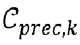
said method comprising: - for each receiver among the plurality of receivers, computing, at said receiver, an analog precoding matrix F RF,k associated to said receiver; and
- using at least one computed analog precoding matrix for processing at least one signal to transmit from the transmitter to at least one receiver;
- /a/ for each subcarrier, performing a Singular Value Decomposition, SVD, on a channel matrix associated to said receiver and to said each subcarrier;
- /b/ for each subcarrier, determining a first decomposition matrix
V k (l) based on the relative SVD; - /c/ determining an analog precoding codeword which optimizes a first function g 1(
V k (1), ... ,V k (L), F ) ofV k (1),...,V k (L) and F, for a plurality of
- By a system supporting "both analog and digital beamforming" it is meant that the system supports digital and/or analog precoding (in which case the transmitter comprises components for performing digital and/or analog precoding) and/or digital and/or analog combining (in which case the transmitter comprises components for performing digital and/or analog combining). For instance, such a system may support hybrid (both digital and analog) precoding and hybrid combining, or hybrid precoding and analog-only combining, etc.
- The method may be performed in a system enabling a process of data on multiple carrier frequency (for instance, a wide band communication system, which may support an OFDM method), or on only one carrier frequency (for instance, a narrow band communication system).
- The wording "receiver" may include a device that receives a signal from the transmitter, as well as a user equipment, a mobile station, etc.
- It is meant by "analog/digital precoding/combining matrix" a matrix specifically associated to one receiver. The whole set of analog/digital precoding/combining matrices is referred to as an analog/digital precoder/combiner. For instance, F BB = [ F BB,1 ... F BB,k ... F BB,K ], is a digital precoder, and each F BB,k is a digital precoding matrix associated to a receiver k.
- Of course, any letter or group of letters ( F BB, g 1 (
V k (1),...,V k (L),F ), ...) which is used for identifying a function, a matrix, or any mathematical entity, is simply intended to simplify reading and understanding of the present invention, and does not represent any limitation of the principles and technical features of the invention to these letters or denominations. - Furthermore, as mentioned before, any of wordings "analog", "RF" or "RF domain" may be used without distinction. Similarly, any of wordings "digital", "base band" or "base band domain" may be used without distinction.
- By "codebook", it is meant a set of predetermined matrices or vectors from which the precoding/combining matrices, or columns of precoding/combining matrices, are chosen. Elements of a codebook are referred to as "codewords". For instance, an element of a codebook corresponding to a RF precoding matrix is referred to as an analog precoding codeword (or RF precoding codeword), and an element of a codebook corresponding to a RF combining matrix is referred to as an analog combining codeword (or RF combining codeword).
- As detailed later, a "channel matrix associated to a receiver" refers to a Channel State Information at the Receiver (CSIR) matrix. This CSIR may be know perfectly, or estimated, for instance by a downlink (DL) estimation procedure based on pilots.
- By "optimize", it is meant either maximize or minimize, depending on the criterion and the first function that is used.
- After obtaining CSIR, a Channel State Information at the Transmitter (CSIT) is usually acquired by Channel State Information (CSI) feedback. In case of a large number of transmitting and receiving antennas (also referred to as "transmit and receive antennas"), each user channel is a matrix with very large dimensions and the signaling overhead for the CSI feedback becomes unaffordable.
- In the present invention, since the computations in RF domain and in base band domain are separated, the signaling overhead for the CSI feedback is reduced.
- Indeed, after the computation of the RF precoder and combiner, the equivalent user channel, which is the user channel after RF beamforming and combining, is fed back to the transmitter. Since the number of transmit and receive RF chains is much smaller than the number of transmit and receive antennas, the dimensions for the equivalent user channel is much smaller than the dimension of the original user channel. As a result, the feedback overhead is largely reduced.
- Furthermore, as detailed after, the computation of the analog precoding matrices as performed in steps /a/, /b/ and /c/ enables to maximize the sum rate of the system.
- More precisely, the invention addresses the problem of solving the following sum rate optimization problem:


- In the general case of a system in which L ≥ 1 (one subcarrier, or a plurality of subcarriers), the first function may be given by:

- tr( A ) denotes a trace of a matrix A;
- AH denotes a conjugate transpose matrix of a matrix A;
- Lr
k is a number of receiving analog chains at said receiver; -
V k (l) is the first decomposition matrix associated to the receiverk for a subcarrier l; - In the following, when L = 1,
V k (1) is referred to asV k, in order to simplify the notations. - When the number of subcarriers is equal to 1 (L = 1), the above optimization problem, that is the minimization of the function


- That means that the above optimization problem may be solved, in the specific case where L = 1, by choosing:

- More generally, in the case of a single carrier system (L = 1), the optimization problem may be written:


- For solving this optimization problem, it is proposed to choose, at each receiver k, an RF precoding matrix F RF,k in the RF precoding codebookand/or an RF combining matrix W RF,k in the RF combining codebook
 such that a quantity

- A plurality of criteria, which are alternative solutions for solving the same technical problem, may be used for the minimization of ΔRk.
- As mentioned before, for a number of subcarriers equal to 1, the first function g 1(
V k,F ) may be given by:
- In this case, the optimization of the first function is a minimization.
- Alternatively, for a number of subcarriers equal to 1, and when each analog precoding codeword F is chosen among a set of columns of a predetermined matrix having a number of rows equal to a number of antennas of the transmitter and a number of columns grower or equal than Lr
k , said matrix being relative to Discrete Fourier Transform, DFT, matrix, the first function g 1(V k,F ) may be given by:
- Lr
k is a number of receiving analog chains at said receiver; - |Q| denotes a magnitude of a complex Q;
- AH denotes a conjugate transpose matrix of a matrix A; and
- A (:,j) is a j-th column of a matrix A.
- In this case, the maximization may include:
- for each column c i of said predetermined matrix, calculating::

- selecting columns c i corresponding to Lr
k largest values of ti among all values of ti . - In another embodiment, the first function g 1 (
V k,F) may be given by:
- AH denotes a conjugate transpose matrix of a matrix A; and
- λmin ( A ) denotes a minimal eigenvalue of a matrix A .
- By a "matrix being relative to DFT matrix", it is meant that the matrix may be a DFT matrix, or an oversampled DFT matrix, which is a matrix constructed by re-normalizing a sub-matrix selected from a DFT matrix.
- For instance, an Nt x NQ
t (with NQt ≥ Nt ) oversampled DFT matrix may be constructed by re-normalizing (which means performing operations such that each column has unit norm) a sub-matrix of the first Nt rows of a NQt point DFT matrix. - The NQ
t point DFT matrix may be an NQt x NQt matrix of the form:

- The NQ
t point DFT matrix W is unitary, and its columns are orthogonal. - For an oversampled DFT matrix, it is possible to show that, for two columns cn and cm (with cn ≠ cm ):
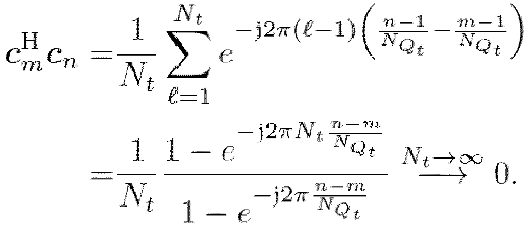
- Still in the case where the number of subcarriers is equal to 1, and when each analog precoding codeword F is a column of a predetermined matrix having a number of rows equal to a number of antennas of the transmitter and a number of columns grower or equal than Lr
k , said matrix being relative to Discrete Fourier Transform, DFT, matrix, the first function g 1(V k, F ) of step /c/ may be function of:
- C i-1 is composed from at least one column of said predetermined matrix;
- F is different from all the columns of C i-1;
- AH denotes a conjugate transpose matrix of a matrix A; and
- λmin ( A ) denotes a minimal eigenvalue of a matrix A .
- In this embodiment, step /c/ is performed iteratively.
- This is actually a specific implementation for the above optimization problem, namely the maximization of the function


- That means that an optimal solution for finding F which maximizes

k !(Q - Lrk )!) possible candidate of F and find the one with the smallest eigenvalue. - Since the computational complexity may become high, the matrix F may be selected column by column as proposed in this specific implementation.
- It is also possible to compute analog combining matrices according to a similar concept. More specifically, it may be assumed in the general method (and in any of the previous embodiments of the general method):
- that each receiver among the plurality of receivers is associated to a relative set of analog combining codewords,

- that, for each receiver among the plurality of receivers and for each subcarrier among the plurality of subcarriers, a second decomposition matrix
U k (l) is determined, based on the relative SVD performed in step /a/; - and that the method further comprises, for each receiver among the plurality of receivers:
- computing, at said receiver, an analog combining matrix W RF,k associated to said receiver, said computation including:
- determining an analog combining codeword which optimizes a second function g2 (
U k (1), ... ,U k (L),W ) ofU k (1), ... ,Uk (L) and W, for a plurality of
- determining an analog combining codeword which optimizes a second function g2 (
- In the case of a multi carrier system (L ≠ 1), the second function may be given by:

- tr( A ) denotes a trace of a matrix A;
- AH denotes a conjugate transpose matrix of a matrix A;
- Lr
k is a number of receiving analog chains at said receiver; -
U k (l) is the second decomposition matrix associated to the receiver k for a subcarrier l; - In the following, when L = 1,
U k (1) is referred to asU k , in order to simplify the notations. - When the number of subcarriers is equal to 1 (L = 1), the above optimization problem, that is the minimization of the function


- That means that the above optimization problem may be solved, in the specific case where L = 1, by choosing:

- More generally, as for the computation of analog precoding matrices, when L = 1, it is possible to choose the analog combining matrices among a plurality of analog combining codewords in order to minimize ΔRk .
- As mentioned before, when the number of subcarriers is equal to 1, the second function g2 (
U k, W ) may be given by:
- In this case, the optimization of the second function is a minimization.
- Alternatively, when the number of subcarriers is still equal to 1, and when each analog precoding codeword F is chosen among a set of columns of a predetermined matrix having a number of rows equal to a number of antennas of the transmitter and a number of columns grower or equal than Lr
k , said matrix being relative to Discrete Fourier Transform, DFT, matrix, the second function g 2(U k,W ) may be given by:
- Lr
k is a number of receiving analog chains at said receiver; - |Q| denotes a magnitude of a complex Q;
- AH denotes a conjugate transpose matrix of a matrix A; and
- A (:,j) is a j-th column of a matrix A.
- In the previous embodiment, the maximization of the second function may include:
- for each column c i of said predetermined matrix, calculating:

- selecting columns c i corresponding to Lr
k largest values of bi among all values of bi . - Alternatively, still when the number of subcarriers is equal to 1, the second function g2 (
U k,W ) may be given by:
- AH denotes a conjugate transpose matrix of a matrix A; and
- λmin ( A ) denotes a minimal eigenvalue of a matrix A .
- When each analog combining codeword W is a column of a predetermined matrix having a number of rows equal to a number of antennas of the transmitter and a number of columns grower or equal than Lr
k , said matrix being relative to Discrete Fourier Transform, DFT, matrix, then, in step /c/ the second function g2 (U k,W ) may be function of:
- Z i-1 is composed from at least one column of said predetermined matrix;
- W is different from all the columns of T i-1;
- AH denotes a conjugate transpose matrix of a matrix A; and
- λmin ( A ) denotes a minimal eigenvalue of a matrix A .
- In this case, the optimization of the second function is a maximization and step /c/ may be performed iteratively.
- As for the computation of analog precoding matrices, this is actually a specific implementation for the above optimization problem, namely the maximization of the function

- In a possible embodiment, the method may further comprise:
- for each receiver among the plurality of receivers, receiving, at the transmitter, an estimation of an equivalent user channel between the transmitter and said each receiver;
- recursively computing, at the transmitter:
- a first set of digital combining matrices, each digital combining matrix of said first set being associated to a receiver among the plurality of receivers, based on the received estimation of the equivalent user channel and on the computed analog combining matrices; and
- a second set of digital precoding matrices, each digital precoding matrix of said second set being associated to a receiver among the plurality of receivers, based on the received estimation of the equivalent user channel and at least one digital combining matrix among the first set.
- The recursive computation may include:
- /d/ For each receiver k among the plurality of K receivers,
- Calculate:

-

-

- F BB,l is a current digital combining matrix associated to a receiver l;
- σ 2 is a variance of a signal noise;
- W RF,k is the computed analog combining matrix associated to the receiver k;
- tr(A) is the trace of a matrix A;
- A H denotes a conjugate transpose matrix of a matrix A.
-
- Update the relative digital combining matrix W BB,k according to:

- A -1 denotes an inverse of a matrix A;
- And calculate:

- I is a matrix identity;

- W H is a block diagonal matrix whose blocks are equal to

- M is a block diagonal matrix whose blocks are equal to M 1, ...,M K ;
- R is a block diagonal matrix whose blocks are equal to

- P is an average total transmitting power.
- Calculate the second set of digital precoding matrices from F.
- Calculate:
- It is mean by "current" value a value at a current iteration.
- Once the analog precoding and combining matrices are determined, a CSIT is fed back to the transmitter and the digital precoding and combining matrices may be determined based on this CSIT.
- Another aspect of the invention relates to a receiver configured to receive data from a transmitter able to serve a plurality of receivers, in a communication system enabling both analog and digital beamforming, and wherein a frequency band comprises at least one subcarrier,
said receiver being associated to a setof analog precoding codewords,
said receiver comprising a circuit for computing an analog precoding matrix F RF,k, characterized in that the computation of the analog precoding matrix comprises: - /a/ for each subcarrier, performing a Singular Value Decomposition, SVD, on a channel matrix associated to said each subcarrier;
- /b/ for each subcarrier, determining a first decomposition matrix
V k (l) based on said SVD; and - /c/ determining an analog precoding codeword which optimizes a first function g 1(
V k (1),...,V k (L),F ) ofV k (1),...,V k (L) and F, for a plurality of
- In complement, this receiver being further may be associated to a relative setof analog combining codewords, and for each subcarrier among the plurality of subcarriers, a second decomposition matrix

U k (l) may be determined, based on said SVD;
said receiver further comprising a circuit for computing an analog combining matrix W RF,k, said computation including: - determining an analog combining codeword which optimizes a second function g 2 (
U k (1), ...,U k (L),W ) ofU k (1),...,U k (L) and W, for a plurality of
- Yet another aspect of the invention relates to a communication system enabling both analog and digital beamforming, comprising a transmitter being able to serve a plurality of receivers, wherein each receiver is defined as mentioned before.
- A last aspect relates to a computer program product comprising a computer readable medium, having thereon a computer program comprising program instructions. The computer program is loadable into a data-processing unit and adapted to cause the data-processing unit to carry out all or part of the method described above when the computer program is run by the data-processing unit.
- Other features and advantages of the method and apparatus disclosed herein will become apparent from the following description of non-limiting embodiments, with reference to the appended drawings.
- The present invention is illustrated by way of example, and not by way of limitation, in the figures of the accompanying drawings, in which like reference numerals refer to similar elements and in which:
-
Figure 1 represents an example of system supporting both analog and digital beamforming in which the present method can be performed; -
Figure 2 is a flow chart describing a possible embodiment of the present invention; -
Figure 3 is a flow chart describing a computation of RF precoders and combiners in a possible embodiment of the present invention; -
Figure 4 is a flow chart describing a computation of Base Band precoders and combiners in a possible embodiment of the present invention; -
Figure 5 represents another example of system supporting both analog and digital beamforming in which the present method can be performed; -
Figure 6 is a possible embodiment for a device that enables the present invention. - Expressions such as "comprise", "include", "incorporate", "contain", "is" and "have" are to be construed in a non-exclusive manner when interpreting the description and its associated claims, namely construed to allow for other items or components which are not explicitly defined also to be present. Reference to the singular is also to be construed in be a reference to the plural and vice versa.
-
Figure 1 represents an example of system supporting both analog and digital beamforming in which the present method can be performed. - According to
figure 1 , the system includes a transmitter 11 equipped with Nt transmit antennas (or "transmitting antennas", or "transmitter antennas") 121, ..., 12Nt, wherein the transmitter 11 is able to jointly serve K (with K ≥ 2)receivers 12k. - Each
receiver 12k is equipped with Nrk receive antennas (or "receiving antennas", or "receiver antennas") 131, ..., 13rk and is able to receive Nsk data streams from the transmitter 11. - The total number of streams I1, I2, ..., INs transmitted by the transmitter 11 is thus:

- It is assumed that the transmitter 11 has Lt transmitting Radio Frequency (RF)
chains 111, ..., 11Lt and that eachreceiver 12k has Lrk receivingRF chains 141, ..., 14Lrk . - The following constraints are also assumed:

- At the transmitter 11, data streams I1, I2, ..., INs are processed by a
base band precoder 110, F BB, which is a complex matrix (that is, a matrix with complex components) of dimensions Lt × Ns, followed by anRF precoder 120, F RF, which is a complex matrix of dimensions Nt × Lt. - The
base band precoder 110 can be written F BB = [ F BB,1 ... F BB,k ... F BB,K ], wherein, for 1 ≤ k ≤ K, F BB,k is a complex matrix of dimensions Lt x Nst . F BB,k is referred to as the base band precoding matrix (or "digital precoding matrix") associated to the k-th receiver 12k. - The RF precoder 120 can be written F RF = [ F RF,1 ... F RF,k ... F RF,K ], wherein, for 1 ≤ k ≤ K, F RF,k is a complex matrix of dimensions Nt × Lr
k . F BB,k is referred to as the RF precoding matrix (or "analog precoding matrix") associated to the k-th receiver 12k. - At the k-
th receiver 12k (where k is an integer, with 1 ≤ k ≤ K), the receiving data streams pass through anRF combiner 140k, W RF,k, which is a complex matrix of dimensions Nrk x Lrk , followed by abase band combiner 150k, W BB,k, which is a complex matrix of dimensions Lrk x Nsk . - After processing by the
base band combiner 150k, the k-th receiver 12k outputs Nsk data streams O1, O2, ..., ONsk . - Therefore, the narrow band block fading transmission for the signal received the k-
th receiver 12k (where k is an integer, with 1 ≤ k ≤ K) is:
- M H denotes the conjugate transpose matrix of a matrix M,
-

th receiver 12k, -

th receiver 12k, -

th receiver 12k, and
receivers 12k, - n k is the noise vector for the k-
th receiver 12k. - In the case the user channel (or "channel state information", CSI) H k is not perfectly known at the receiver, a channel estimation may be performed in order to estimate the CSI at the Receiver (CSIR). Any method of the state of the art for estimating the CSIR may be performed. In this disclosure, Hk may denote the perfect CSIR if it is known, or it may denote an estimation of CSIR obtained by a dedicated method.
- For example and without limitation, it may be assumed that the power of data symbol vector satisfies
 denotes the statistical expectation, and that n k is a Gaussian vector. For instance, n k may be a white Gaussian noise:
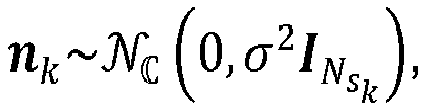

k . - It may also be assumed that the RF and base band precoders are subjected to the following total power constraint:

- The RF precoder/combiners of the hybrid architecture may be implemented by phase shifters, each transceiver being connected to each antenna through a network of phase shifters. In this case, it may be assumed for example that the matrices F RF and W RF,1, ...,W RF,K satisfy:


- Thus, the analog precoding matrices F RF,1 , ...., F RF,K and the analog combining matrices W RF,1 , ...,W RF,K can take only certain values. Hence, these matrices may be selected from finite-size codebooks.
- It is assumed that, for any receiver indexed by k (1 ≤ k ≤ K), F RF,k takes its value in a codebook, where

 , where

- Any types of codebooks may be chosen forand
 . For instance, Grassmannian codebooks or beamsteering codebooks may be used.
- Elements of a codebook are referred to as codewords. More specifically, in order to ease the reading of the present description, an element of a codebook corresponding to a RF precoding matrix is referred to as an analog precoding codeword (or RF precoding codeword), and an element of a codebook corresponding to a RF combining matrix is referred to as an analog combining codeword (or RF combining codeword).
- Of course, the architecture represented in
figure 1 is only an example of a system in which the present method may be performed. Other systems may be considered. For instance, at receivers, there may be only analog combiners instead of both analog and digital combiners. Also, there may be other components than those represented infigure 1 , and alternative equations for modeling the system may be used instead of those introduced above. -
Figure 2 is a flow chart describing a possible embodiment of the present invention. - In a
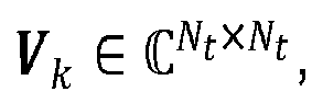
first step 201, Channel State Information at Receiver (CSIR) is received and is available at receivers. - For instance, a set of CSIR matrices { H k } k=1 ,...,K, each matrix H k ∈

- As mentioned before, any estimation method of the state of the art can be used. For instance, a Minimum Mean-Square Error (MMSE) estimation method, or a Bayesian estimation method may be performed.
- Optionally, after
step 201, a predefined user scheduling procedure may be performed to select users for the downlink (DL) transmission, the selected multiple users sharing the same radio resources. - In
step 202, which includessteps - More specifically, in
step 202a, a Singular Value Decomposition (SVD) is performed on the CSIR matrix H k , for each receiver k:






- It is assumed for instance that the singular values in ∑ k are ranked in descending order. The columns of
U k (resp.V k ) are the largest Lrk left (resp. right) singular vectors for the singular value decomposition of H k. - In
step 202b, at each receiver of index k, the RF precoding matrix F RF,k and the RF combining matrix W RF,k are chosen among codebooks Cprec,k and Ccomb,k respectively, based onU k andV k obtained by the SVD. - More precisely, the sets of matrices F RF,k and W RF,k (k = 1, ..., K) may be chosen in order to maximize (or, at least, approach the maximum) the sum rate RRF,BC of the system equivalent Broadcast Channel (BC) under RF precoding/beamforming, that is, for the equivalent user channel (which is the user channel after RF precoding and combining)


- According to uplink downlink duality, the sum rate RRF,BC of the system equivalent Broadcast Channel (BC) is equivalent to the sum rate RRF,MAC of the system equivalent Multiple-Access Channel (MAC). Therefore:


- det(M) denotes the determinant of a matrix M;
-

-

- I is the identity matrix;
- P is the average total transmitting power.
- In the last equation, the first term q 1, can be maximized using local CSIR, and the second term q 2 is lower or equal to zero. The maximum value of q 2, which is zero, can actually only be reached with full CSI at the Transmitter (CSIT), which is unknown at the first stage of calculating RF precoder/combiner. Hence, only the first term is considered in the optimization problem to solve.
- Furthermore, it may be noticed that, in case of a massive MIMO system, if the K users (receivers) are randomly located, the probability that these users have disjoint Angle Of Arrival (AOA) support is high, which means that the second term q 2 is close to zero. This means that, in case of a massive MIMO system, a solution which maximizes the first term q 1 is a good solution for maximizing the sum rate.
- Therefore, matrices F RF,k and W RF,k are chosen so as to maximize q 1. For this purpose, each RF precoding matrix F RF,k and each RF combining matrix W RF,k associated to a receiver k is chosen so as to maximize:

- The optimization problem to solve can thus be formulated as:



r is the complex Stiefel manifold of orthonormal Lr frames in
- In the case where there are no constraints due to limited phase resolution on F RF,k and W RF,k, an optimal solution for this optimization problem is given by:

U k andV k are determined based on a SVD on H k, as mentioned before. - If however there are constraints due to limited phase resolution on F RF,k and W RF,k, as considered in the present case, then F RF,k and W RF,k may be selected from predefined codebooksand
 .
.
- Hence, a solution is to choose, at each receiver k, an RF precoding matrix F RF,k in the RF precoding codebookand an RF combining matrix W RF,k in the RF combining codebook
 , such that a quantity


- Examples of criterion enabling to choose such matrices F RF,k and W RF,k at a receiver k are presented on section relative to
figure 3 . - According to
figure 2 , afterstep 202b, a channel estimation method may be performed for estimating the equivalent user channel
- Since this equivalent user channel has far smaller dimension than the original channel, obtain
full CSIT 
full CSIT 
- Then, each receiver may quantize and feedback to the transmitter, as well as the index of the chosen RF precoding codeword F RF,k (step 203).
- At
step 204, the index of the chosen W RF,k can also be fed back to the transmitter. This step is optional, and not necessary in the case of a massive MIMO system, as explained further. - At
step 205, the base band precoding and combining matrices are calculated at the transmitter. - Then, the base band combining matrices W BB,1 , ..., W BB,K may be fed back from the transmitter (step 206). This
step 206 is optional. Alternatively, each RX k can calculate the relative W BB,k based on a precoded demodulation reference signal and the knowledge of the base band precoder FBB. - Each receiver k can then apply its relative RF combining matrix W RF,k and its relative base band combining matrix

- Each receiver can apply the RF precoder FRF and the base band precoder F BB .
-
Figure 3 is a flow chart describing a computation of RF precoders and combiners in a possible embodiment of the present invention. This computation is performed at one receiver among the plurality of receivers of the system. Hence, the following computation method shall be applied to every receiver. - A CSIR matrix H k (301) is available at receiver k. As mentioned above, an SVD is performed on this CSIR matrix (
step 202a):
- The
step 202b of determining the RF precoding and combining matrices may be decomposed into two steps: - choose (step 303) the RF precoding matrix relative to receiver k as the analog precoding codeword which optimizes (that is, minimizes or maximizes) a first function g1(
V k, F ):
- choose (step 304) the RF combining matrix relative to receiver k as the analog combining codeword which optimizes (that is, minimizes or maximizes) a second function g 2(
U k,W ):
- At the output, matrices F RF,k and W RF,k (305) are available at receiver k.
- Examples of optimizations relative to functions g 1(
V k , F ) and g2 (U k,W ) (steps 303 and 304) are now presented. - In a possible embodiment, F RF,k or W RF,k may be chosen according to the following first criterion:


- According this criterion, the RF precoding and combining matrices are chosen as the closest to the optimal one, in terms of a mathematical distance (for instance, the chordal distance).
- This first criterion may be used, for instance, if the predefined codebooksand
 are random uniform codebooks or Grassmannian codebooks.
- If the analog precoding codebook and the analog combining codebook are beamsteering codebooks, this first criterion may be expressed in a different way.
- A beamsteering codebook is defined as follows, in the case of an RF precoding codebook (the case of an RF combining codebook may be considered similarly): each column of an RF precoding codeword is chosen from one column of a Discrete Fourier Transform (DFT) matrix, or from one column of an oversampled DFT matrix, wherein an Nt x NQ
t oversampled DFT matrix is constructed by re-normalizing a sub-matrix of the first Nt rows of a NQt point DFT matrix. - For example, it may be assumed that NQ
t = TNt, where NQt is the total number of possible phases for the phase shifter, and T is the oversampling ratio (T > 1). Each column of a precoding codeword may be selected from an Nt x NQt oversampled DFT matrix. - An advantage of using analog precoding codebooks obtained from a DFT or an oversampled DFT matrix if that the feedback of the matrices F RF,k does not require much feedback resource.
- If the analog precoding codebook and the analog combining codebook are beamsteering codebooks, then:


- |Q| denotes a magnitude of a complex Q; and
- M(:j) is a j-th column of a matrix M.
- Thus, a second criterion for chosing F RF,k or W RF,k in an alternative embodiment is:


- Actually, the first and second criteria are equivalent in case of beamsteering codebooks.
- For implementing this second criterion in the case of the analog precoding codebook F RF,k, the following algorithm may be performed:
- for each column c i of the Nt × Nt DFT matrix or of the Nt × NQ
t oversampled DFT matrix associated to the RF precoding codebook, calculate: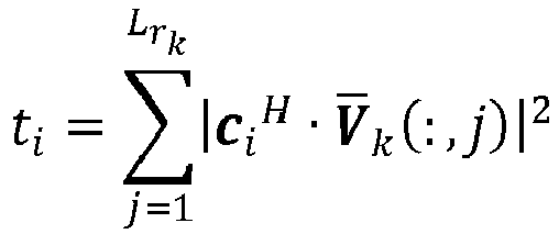
- define the columns of F RF,k as the columns c i which correspond to the Lr
k largest values of ti among all calculated values of ti . - As for the last step, this means that the first column of F RF,k is chosen as the column c i which corresponds to the largest value of ti . Then, the second column of F RF,k is chosen as the column c i which corresponds to the second largest value of ti , etc.
- In other word, let assume that

- Then, if for i = 1, ..., Lr
k , c i is the column which corresponds to ti (which means that ti has been calculated from c i according to the previous equation), F RF,k is defined as:
- Similarly, in the case of the analog combining codebook W RF,k, the following algorithm may be performed:
- for each column c i of the DFT matrix or the Nt × NQ
t oversampled DFT matrix associated to the RF precoding codebook, calculate: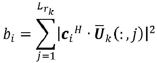
- define the columns of W RF,k as the columns c i which correspond to the Lr
k largest values of bi among all calculated values of bi . - In another embodiment, F RF,k or W RF,k may be chosen according to the following third criterion:


- This criterion also enables to solve the problem of minimizing ΔRk . Indeed, let:


- Then, it can be shown that:

- Since 0 ≤ ρ 1 ≤ 1 and 0 ≤ ρ 2 ≤ 1, when the sizes of codebooks increase, ρ 1 and ρ 2 approach 1, and the rate loss due to the quantization decreases (and approaches zero).
- This third criterion may be used, for instance, if the predefined codebooksand
 are random uniform codebooks or Grassmannian codebooks.
- If the analog precoding codebook is a beamsteering codebook, the following procedure, relative to third criterion, may be used for computing the analog precoding matrices:
- Initialization:
- select a column f 1 from the beamsteering codebook such that

- let C 1 = f 1;
- select a column f 1 from the beamsteering codebook such that
- For i = 2 ... Lr
- Select a column fi from the beamsteering codebook which is different from the columns of C i-1 such that
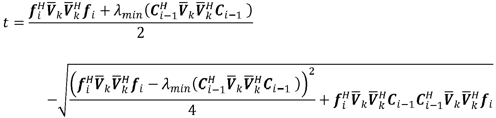
- Let C i = [ C i-1 f i ] be the concatenate matrix whose first columns are all columns of C i-1, and last column is f i .
- Select a column fi from the beamsteering codebook which is different from the columns of C i-1 such that
- The analog precoding matrix associated to receiver k is F RF,k = C L
r . - Similarly, if the analog precoding codebook is a beamsteering codebook, the analog combining matrices may be calculated as follows:
- Initialization:
- select a column W 1 from the beamsteering codebook such that

- let Z 1 = W 1;
- select a column W 1 from the beamsteering codebook such that
- For i = 2 ... Lr
- Select a column w i from the beamsteering codebook which is different from the columns of Z i-1 such that
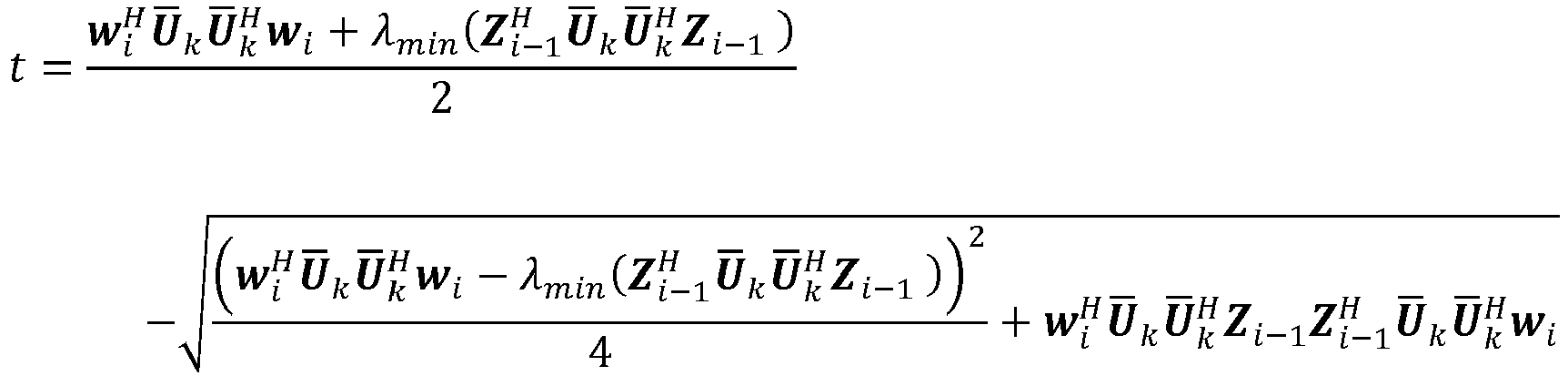
- Let Z i = [ Z i-1 wi ] be the concatenate matrix whose first columns are all columns of Z i-1, and last column is w i.
- Select a column w i from the beamsteering codebook which is different from the columns of Z i-1 such that
- The analog combining matrix associated to receiver k is W RF,k = Z L
r . -
Figure 4 is a flow chart describing a computation of Base Band precoders and combiners in a possible embodiment of the present invention. - In a possible embodiment of the present invention, the Base Band precoders and combiners may be computed (step 205), based on the set of equivalent user channels

- at
step 402, initialize the base band precoder F BB = [ F BB,1 ... F BB,K ] and the set of base band combining matrices W BB,1 , ..., W BB,K ; - at
step 403, perform a stop test based on a stop criterion:- if the test is positive (OK), the iterative algorithm stops, and current F BB and W BB,1 , ..., W BB,K (406) are outputted;
- if the test is negative (KO):
- update (404) W BB,1 , ..., W BB,K based on the set of equivalent
user channels 
- update (405) F BB based on current W BB,1 , ..., W BB,K and on the set of equivalent
user channels 
- perform the stop test (403).
- update (404) W BB,1 , ..., W BB,K based on the set of equivalent
- The invention is not limited to this algorithm, and the Base Band precoders and combiners may be computed by any other method of the state of the art.
- In a non-limiting manner, examples of equations for the algorithm are given below.
- At
step 402, F BB may be randomly initialized and normalized to satisfy the power constraint:

- Alternatively, F BB may be initialized with the first Ns columns of the matched filter, which is
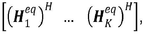


- The base band combining matrices W BB,1 , ..., W BB,K may also be randomly initialized. Alternatively, they may be initialized from the computed F BB, for instance based on the equations mentioned in the following section.
- The stop test performed at
step 403 may be based on a convergence criterion. For instance it may be decided that the algorithm stops when: - the distance (in a mathematical sense, for instance the chordal distance) between current F BB and previously calculated F BB is below a first predetermined threshold; and
- for each receiver k, the distance (in a mathematical sense, for instance the chordal distance) between current

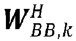
-
Steps - For each k, k = 1, ... , K:
- Calculate the effective noise covariance matrix for receiver k, given by:

- Calculate the Minimum Mean Square Error (MMSE) receive filter for receiver k:

- Calculate the weighting matrix at receiver k for the weighted MMSE minimization optimization which achieves the same Karush-Kuhn-Tucker (KKT) point as the sum rate maximization optimization:

- End for
- Calculate the concatenated equivalent noise covariance matrix after the RF domain processing, which is the block diagonal matrix composed of matrices


- Calculate the transmit filter which is the optimal solution for the weighted MMSE minimization (which is also the one which achieves the same KKT point as the weighted sum rate maximization):

-

- M =blockdiag( M 1 ... M K );
-

-

- tr( A ) is the trace of a matrix A .
-
- Normalize the average transmit power to satisfy the power constraint:

- Calculate the effective noise covariance matrix for receiver k, given by:
- As mentioned before, steps 404 and 405 are iteratively performed until a stop criterion is met.
- Of course, the method presented above for calculating the base band precoder and combiner is a possible embodiment of the present invention, but the invention is not limited to this method.
- Other choices of base band beamforming methods may be used, for instance a zero forcing base band beamforming, a block diagonalization base band beamforming, etc.
-
Figure 5 represents another example of system supporting both analog and digital beamforming in which the present method can be performed. - More precisely, only the transmitter is represented in
figure 5 , so as not to overload the figure. - The present invention may also be used in a wideband communication system, for instance in a system supporting orthogonal frequency-division multiplexing.
- The main difference with the system represented in
figure 1 is that the frequency band is divided into a plurality of subcarriers. Let L denotes the number of subcarriers. - In such a system, there are L base band combining matrices W BB,k [1], ..., W BB,k [L] associated to a receiver k, and L base band precoders F BB [1], ..., F BB [L] (
elements figure 5 ). Also, the user channel Hk[l] depends on the l-th subcarrier frequency. - For the kth user's, the RF combining matrices

- The received symbol at receiver k on the subcarrier l is:


- The system performance may be evaluated by the sum rate for all the users and in all the subcarrier frequency.
- Similarly to the hybrid beamforming in a narrow band system (as for instance the system represented in
figure 1 ), an RF precoding/combining design criterion if there is no constraint on the limited phase for

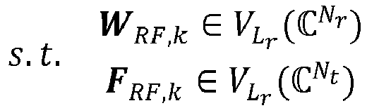
- Unlike the narrow band case where L = 1 and the optimal solution to the problem above is the left (resp. right) singular subspace spanned by the Lr largest left (right) singular vectors, the wideband case does not seem to have a closed form solution to the problem above.
- Therefore, a sub-optimal criterion may be used.
- Rather than maximizing the sum rate described in the optimization problem above, it is possible to maximize (or try to maximize) the average signal strength:

- The optimization problem to solve in this case may be written:

 .
.
- This optimization problem may be solved by selecting

- let X 1 =
U k [1],...,X L =U k [L]; - let d2 ( A, B ) = n - tr( AA H BB H ), with

- for each k, 1 ≤ k ≤ K, the RF combining matrix may be expressed as:


- Similarly:
- let Y 1 =
V k[1],..., Y L =V k[L]; - for each k, 1 ≤ k ≤ K, the RF precoding matrix may be expressed as:


- It has to be noted that, when L = 1, which corresponds to a narrow band system, then:


- That means that, when L = 1, calculating W RF,k and F RF,k according to the above criterion is equivalent to calculating W RF,k and F RF,k according to the first criterion presented in the narrowband case:


- Actually, for a narrow band system, the chosen precoder/combiner which corresponds to a maximization of the sum rate also maximizes the signal strength.
-
Figure 6 is a possible embodiment for a device that enables the present invention. - In this embodiment, the
device 600 comprise a computer, this computer comprising amemory 605 to store program instructions loadable into a circuit and adapted to causecircuit 604 to carry out the steps of the present invention when the program instructions are run by thecircuit 604. - The
memory 605 may also store data and useful information for carrying the steps of the present invention as described above. - The
circuit 604 may be for instance: - a processor or a processing unit adapted to interpret instructions in a computer language, the processor or the processing unit may comprise, may be associated with or be attached to a memory comprising the instructions, or
- the association of a processor / processing unit and a memory, the processor or the processing unit adapted to interpret instructions in a computer language, the memory comprising said instructions, or
- an electronic card wherein the steps of the invention are described within silicon, or
- a programmable electronic chip such as a FPGA chip (for « Field-Programmable Gate Array »).
- For instance, the device may be comprised in a user equipment (or in a mobile station), and the computer may comprise an
input interface 603 for the reception of CSIR according to the invention and anoutput interface 606 for providing the RF precoding and combining matrices. - The device may alternatively be comprised in a transmitter (for instance, into a base station), and the computer may comprise an
input interface 603 for the reception of equivalent CSIT according to the invention and anoutput interface 606 for providing the base band precoding and combining matrices. - To ease the interaction with the computer, a
screen 601 and akeyboard 602 may be provided and connected to thecomputer circuit 604. - Furthermore, the flow chart represented in
figure 2 can represent all or part of the steps of a program which may be executed by a processor located in the receiver or in the transmitter. For instance, steps 201 and 202 (including 202a and 202b) may be executed by a device included in a receiver, whilesteps figure 3 may correspond to the flow chart of the general algorithm of a computer program within the meaning of the invention. - A person skilled in the art will readily appreciate that various parameters disclosed in the description may be modified and that various embodiments disclosed may be combined without departing from the scope of the invention.
- Of course, the present invention is not limited to the embodiments described above as examples. It extends to other variants. For instance, in the case of a massive MIMO system, the
step 204 offigure 2 may be skipped. Indeed, for such a system, the columns of the matrices

- Thus, in a massive MIMO system, it can be considered that


Claims (15)
- A method implemented by a computer for enabling both analog and digital beamforming in a communication system including a transmitter (11) being able to serve a plurality of receivers (12k),
wherein a frequency band comprises at least one subcarrier;
wherein each receiver among the plurality of receivers is associated to a relative setof analog precoding codewords,
said method comprising:- for each receiver among the plurality of receivers, computing (202), at said receiver, an analog precoding matrix F RF,k (305) associated to said receiver; and- using at least one computed analog precoding matrix (305) for processing at least one signal to transmit from the transmitter to at least one receiver;characterized in that the computation (202) of the analog precoding matrix associated to a receiver among the plurality of receivers comprises:/a/ for each subcarrier, performing (202a) a Singular Value Decomposition, SVD, on a channel matrix associated to said receiver and to said each subcarrier;/b/ for each subcarrier, determining a first decomposition matrixV k (l) based on the relative SVD;/c/ determining (303) an analog precoding codeword which optimizes a first function g 1(wherein L denotes a number of subcarriers.V k (1),...,V k (L),F ) ofV k (1), ... ,V k (L) and F, for a plurality of
- A method according to claim 1, wherein the first function is given by:
 • tr( A ) denotes a trace of a matrix A;• AH denotes a conjugate transpose matrix of a matrix A;• Lr
k is a number of receiving analog chains at said receiver;•and wherein the optimization (303) of the first function is a minimization.V k (l) is the first decomposition matrix associated to the receiver k for a subcarrier l; - A method according to claim 1, wherein the number of subcarriers is equal to 1,
wherein each analog precoding codeword F is chosen among a set of columns of a predetermined matrix having a number of rows equal to a number of antennas of the transmitter and a number of columns grower or equal than Lrk , said matrix being relative to Discrete Fourier Transform, DFT, matrix,
and wherein the first function g 1(V k, F ) is given by: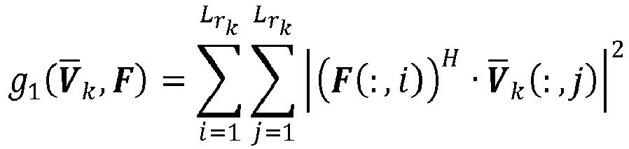 • Lr
• Lrk is a number of receiving analog chains at said receiver;• |Q| denotes a magnitude of a complex Q;• AH denotes a conjugate transpose matrix of a matrix A; and• A (:,j) is a j-th column of a matrix A.and wherein the optimization (303) of the first function is a maximization. - A method according to claim 1, wherein the number of subcarriers is equal to 1, and wherein the first function g 1(
V k,F ) is given by: • AH denotes a conjugate transpose matrix of a matrix A; and• λmin ( A ) denotes a minimal eigenvalue of a matrix A .and wherein the optimization (303) of the first function is a maximization.
 - A method according to claim 1, wherein the number of subcarriers is equal to 1, and wherein each analog precoding codeword F is a column of a predetermined matrix having a number of rows equal to a number of antennas (121, 12Nt) of the transmitter (11) and a number of columns grower or equal than Lrk, said matrix being relative to Discrete Fourier Transform, DFT, matrix;
wherein, in step /c/, the first function g1 (V k,F ) is a function of: • C i-1 is composed from at least one column of said predetermined matrix;• F is different from all the columns of C i-1;• AH denotes a conjugate transpose matrix of a matrix A; and• λmin ( A ) denotes a minimal eigenvalue of a matrix A .wherein the optimization (303) of the first function is a maximization;
and wherein step /c/ is performed iteratively. - A method according to one of the preceding claims, wherein each receiver among the plurality of receivers is associated to a relative setof analog combining codewords,

wherein, for each receiver among the plurality of receivers and for each subcarrier among the plurality of subcarriers, a second decomposition matrixU k (l) is determined, based on the relative SVD performed (202a) in step /a/;
the method further comprising, for each receiver among the plurality of receivers:- computing (202b), at said receiver, an analog combining matrix W RF,k associated to said receiver, said computation including:- determining (304) an analog combining codeword which optimizes a second function g 2 (U k (1),...,U k (L),W ) ofU k (1), ...,U k (L) and W , for a plurality of
- A method according to claim 6, wherein the second function is:
 • tr( A ) denotes a trace of a matrix A;• AH denotes a conjugate transpose matrix of a matrix A;• Lr
k is a number of receiving analog chains at said receiver;•and wherein the optimization (304) of the second function is a minimization.U k (l) is the second decomposition matrix associated to the receiver k for a subcarrier l; - A method according to claim 6, wherein the number of subcarriers is equal to 1,
wherein each analog precoding codeword F is chosen among a set of columns of a predetermined matrix having a number of rows equal to a number of antennas (121, 12Nt) of the transmitter (11) and a number of columns grower or equal than Lrk, said matrix being relative to Discrete Fourier Transform, DFT, matrix,
and wherein the second function g 2 (U k,W ) is given by: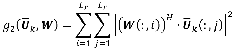 • Lr
• Lrk is a number of receiving analog chains at said receiver;• |Q| denotes a magnitude of a complex Q;• AH denotes a conjugate transpose matrix of a matrix A; and• A (:,j) is a j-th column of a matrix A.and wherein the optimization (304) of the second function is a maximization. - A method according to claim 6, wherein the number of subcarriers is equal to 1, and wherein the second function g 2(
U k, W) is given by: • AH denotes a conjugate transpose matrix of a matrix A; and• λmin ( A ) denotes a minimal eigenvalue of a matrix A .and wherein the optimization (304) of the second function is a maximization.
 - A method according to claim 6, wherein an analog combining codeword W is a column of a predetermined matrix having a number of rows equal to a number of antennas (121, 12Nt) of the transmitter (11) and a number of columns grower or equal than Lrk, said matrix being relative to Discrete Fourier Transform, DFT, matrix;
wherein, in step /c/ the second function g 2 (U k,W) is a function of: • Z i-1 is composed from at least one column of said predetermined matrix;• W is different from all the columns of T i-1;• AH denotes a conjugate transpose matrix of a matrix A; and• λmin ( A ) denotes a minimal eigenvalue of a matrix A,wherein the optimization (304) of the second function is a maximization; and wherein step /c/ is performed iteratively.
 - A method according to any of claims 6 to 10, the method further comprising:- for each receiver among the plurality of receivers, receiving, at the transmitter, an estimation (401) of an equivalent user channel between the transmitter (11) and said each receiver (12k);- recursively computing, at the transmitter:- a first set of digital combining matrices (404), each digital combining matrix of said first set being associated to a receiver among the plurality of receivers, based on the received estimation of the equivalent user channel and on the computed analog combining matrices; and- a second set of digital precoding matrices (405), each digital precoding matrix of said second set being associated to a receiver among the plurality of receivers, based on the received estimation of the equivalent user channel and at least one digital combining matrix among the first set;wherein the recursive computation includes:/d/ For each receiver k among the plurality of K receivers,- Calculate:
 •
• •
• • FBB,l is a current digital combining matrix associated to a receiver l;• σ 2 is a variance of a signal noise;• WRF,k is the computed analog combining matrix associated to the receiver k;• tr(A) is the trace of a matrix A ;• A H denotes a conjugate transpose matrix of a matrix A .- Update the relative digital combining matrix WBB,k according to:
 • A -1 denotes an inverse of a matrix A ;- And calculate:
 • I is a matrix identity;/e/ Define:
 • W H is a block diagonal matrix whose blocks are equal to
 • M is a block diagonal matrix whose blocks are equal to M 1, ..., M K ;• R is a block diagonal matrix whose blocks are equal to
 • P is an average total transmitting power.- Calculate the second set of digital precoding matrices from
F . - A receiver (12k) configured to receive data from a transmitter (11) able to serve a plurality of receivers, in a communication system enabling both analog and digital beamforming and wherein a frequency band comprises at least one subcarrier,
said receiver being associated to a setof analog precoding codewords,
said receiver comprising a circuit for computing (202) an analog precoding matrix F RF,k,
characterized in that the computation of the analog precoding matrix comprises:/a/ for each subcarrier, performing (202a) a Singular Value Decomposition, SVD, on a channel matrix associated to said each subcarrier;/b/ for each subcarrier, determining a first decomposition matrixV k (l) based on said SVD; and/c/ determining an analog precoding codeword which optimizes (303) a first function g 1(wherein L denotes a number of subcarriers.V k (1), ...,V k (L), F ) ofV k (1), ...,V k(L) and F , for a plurality of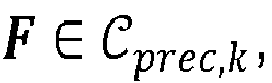
- A receiver according to claim 12, said receiver being further associated to a relative setof analog combining codewords, wherein for each subcarrier among the plurality of subcarriers, a second decomposition matrix

U k (l) is determined, based on said SVD; said receiver further comprising a circuit for computing an analog combining matrix W RF,k, said computation including:- determining an analog combining codeword which optimizes (304) a second function g2 (U k (1), ...,U k (L), W ) ofU k(1), ...,U k (L) and W , for a plurality of
- A communication system enabling both analog and digital beamforming, said system comprising a transmitter (11) being able to serve a plurality of receivers (12k), wherein each receiver is as claimed in any of claims 12 or 13.
- A computer program product, comprising instructions for performing the method as claimed in anyone of claims 1 to 11, when run by a processor.
Priority Applications (5)
| Application Number | Priority Date | Filing Date | Title |
|---|---|---|---|
| EP17305566.6A EP3404843B1 (en) | 2017-05-17 | 2017-05-17 | Method for enabling both analog and digital beamforming |
| CN201880031087.5A CN110622434B (en) | 2017-05-17 | 2018-05-10 | Receiver, communication system and computer-implemented method in a communication system |
| PCT/JP2018/019000 WO2018212258A1 (en) | 2017-05-17 | 2018-05-10 | Receiver, communication system, and method implemented by computer for enabling both analog and digital beamforming in communication system |
| JP2019546053A JP6937836B2 (en) | 2017-05-17 | 2018-05-10 | Methods implemented by receivers, communication systems, and computers that enable both analog and digital beamforming in communication systems. |
| US16/603,779 US11152984B2 (en) | 2017-05-17 | 2018-05-10 | Receiver, communication system, and method implemented by computer for enabling both analog and digital beamforming in communication system |
Applications Claiming Priority (1)
| Application Number | Priority Date | Filing Date | Title |
|---|---|---|---|
| EP17305566.6A EP3404843B1 (en) | 2017-05-17 | 2017-05-17 | Method for enabling both analog and digital beamforming |
Publications (2)
| Publication Number | Publication Date |
|---|---|
| EP3404843A1 true EP3404843A1 (en) | 2018-11-21 |
| EP3404843B1 EP3404843B1 (en) | 2022-12-07 |
Family
ID=58779043
Family Applications (1)
| Application Number | Title | Priority Date | Filing Date |
|---|---|---|---|
| EP17305566.6A Active EP3404843B1 (en) | 2017-05-17 | 2017-05-17 | Method for enabling both analog and digital beamforming |
Country Status (5)
| Country | Link |
|---|---|
| US (1) | US11152984B2 (en) |
| EP (1) | EP3404843B1 (en) |
| JP (1) | JP6937836B2 (en) |
| CN (1) | CN110622434B (en) |
| WO (1) | WO2018212258A1 (en) |
Cited By (6)
| Publication number | Priority date | Publication date | Assignee | Title |
|---|---|---|---|---|
| CN109856606A (en) * | 2019-01-11 | 2019-06-07 | 中国船舶重工集团公司第七二四研究所 | A kind of Two-dimensional electron stabilized platform real-time computing technique structured the formation based on triangle |
| CN110138427A (en) * | 2019-05-15 | 2019-08-16 | 西安科技大学 | Extensive multiple-input and multiple-output mixed-beam forming algorithm based on part connection |
| CN110855337A (en) * | 2019-10-25 | 2020-02-28 | 无锡北邮感知技术产业研究院有限公司 | Hybrid precoding method, base station, electronic device, and storage medium |
| CN113287265A (en) * | 2019-01-17 | 2021-08-20 | 三菱电机株式会社 | Method for enabling analog precoding and analog combining |
| WO2022129237A1 (en) * | 2020-12-16 | 2022-06-23 | Continental Teves Ag & Co. Ohg | Transceiver method between receiver (rx) and transmitter (tx) in an overloaded communication channel |
| CN115733530A (en) * | 2022-11-21 | 2023-03-03 | 电子科技大学长三角研究院(湖州) | A Joint Precoding Method for Reconfigurable Smart Surface-Assisted Millimeter Wave Communication |
Families Citing this family (12)
| Publication number | Priority date | Publication date | Assignee | Title |
|---|---|---|---|---|
| US10951286B2 (en) * | 2019-04-26 | 2021-03-16 | Huawei Technologies Co., Ltd. | Methods and systems for hybrid beamforming for MIMO communications |
| US10938465B1 (en) | 2019-05-14 | 2021-03-02 | Space Exploration Technologies Corp. | Channel aggregation digital beamforming |
| CN110535507A (en) * | 2019-06-17 | 2019-12-03 | 南京邮电大学 | Mixing precoding algorithms of the millimeter wave MIMO based on maximum equivalent channel gain |
| US11876654B2 (en) * | 2020-04-22 | 2024-01-16 | Qualcomm Incorporated | Methods and apparatus for unified codebooks for orthogonal sequence transmission |
| CN111786708B (en) * | 2020-07-02 | 2022-06-07 | 电子科技大学 | Joint channel information acquisition method of large-scale MIMO system |
| CN111865379B (en) * | 2020-07-15 | 2021-12-28 | 南京理工大学 | A Secure Precoding Method Based on Alternating Direction Multiplier Method |
| CN112054826B (en) * | 2020-09-14 | 2021-09-07 | 长沙理工大学 | A single-user low-complexity hybrid precoding method based on intermediate channel |
| CN112737647B (en) * | 2020-12-25 | 2022-07-08 | 杭州电子科技大学 | Millimeter wave large-scale MIMO precoding method based on hybrid connection |
| KR102456042B1 (en) * | 2021-02-03 | 2022-10-19 | 한국과학기술원 | User Interference Control Method and Apparatus for OFDM-Based Hybrid Beamforming in Wideband Downlink System |
| CN113472409B (en) * | 2021-05-19 | 2022-07-15 | 南京邮电大学 | Hybrid pre-coding method based on PAST algorithm in millimeter wave large-scale MIMO system |
| KR102805538B1 (en) * | 2022-04-07 | 2025-05-12 | 한국전자통신연구원 | Beamforming Signal Transmitting and Receiving Method and Signal Transceiver for Implementing the Same |
| CN115102589B (en) * | 2022-06-29 | 2023-07-25 | 内蒙古大学 | Deep learning hybrid precoding method of terahertz large-scale MIMO system |
Citations (5)
| Publication number | Priority date | Publication date | Assignee | Title |
|---|---|---|---|---|
| US20080112504A1 (en) * | 2004-11-05 | 2008-05-15 | University Of Florida Research Foundation, Inc. | Uniform Channel Decomposition For Mimo Communications |
| US20100232352A1 (en) * | 2009-03-10 | 2010-09-16 | Qualcomm Incorporated | Precoding technique for multiuser mimo based on eigenmode selection and mmse |
| US20130301454A1 (en) * | 2012-05-10 | 2013-11-14 | Samsung Electronics Co. Ltd. | Communication method and apparatus using analog and digital hybrid beamforming |
| US20140072068A1 (en) * | 2011-09-30 | 2014-03-13 | Yuan Zhu | Enhanced performance multi-user multiple input output (mu-mimo) radio links |
| US20140093005A1 (en) * | 2012-09-28 | 2014-04-03 | Interdigital Patent Holdings, Inc. | Method for wifi beamforming,feedback, and sounding (wibeam) |
Family Cites Families (9)
| Publication number | Priority date | Publication date | Assignee | Title |
|---|---|---|---|---|
| JP4536780B2 (en) | 2004-11-05 | 2010-09-01 | 株式会社エヌ・ティ・ティ・ドコモ | Multi-user transmission system |
| EP2086140B1 (en) * | 2006-11-22 | 2016-03-09 | Fujitsu Limited | Mimo-ofdm communication system and mimo-ofdm communication method |
| KR20100019929A (en) * | 2008-08-11 | 2010-02-19 | 엘지전자 주식회사 | A method for designing a sc-fdma mimo codebook |
| US9153060B2 (en) * | 2012-04-19 | 2015-10-06 | Ohio State Innovation Foundation | Method for estimating a GRAPPA reconstruction kernel |
| KR102048880B1 (en) * | 2013-04-29 | 2019-11-26 | 삼성전자주식회사 | Method and apparatus for communications in multi-stage beam-forming system |
| CN106253956B (en) * | 2016-08-24 | 2019-06-21 | 东南大学 | Modulo-digital hybrid precoding method based on codebook |
| CN106571858B (en) * | 2016-11-03 | 2020-04-14 | 北京邮电大学 | A hybrid beamforming transmission system |
| US9967014B1 (en) * | 2016-11-09 | 2018-05-08 | Facebook, Inc. | Beamforming in antenna systems |
| US10340975B2 (en) * | 2016-12-15 | 2019-07-02 | Cisco Technology, Inc. | Filter design for access points |
-
2017
- 2017-05-17 EP EP17305566.6A patent/EP3404843B1/en active Active
-
2018
- 2018-05-10 US US16/603,779 patent/US11152984B2/en not_active Expired - Fee Related
- 2018-05-10 JP JP2019546053A patent/JP6937836B2/en not_active Expired - Fee Related
- 2018-05-10 CN CN201880031087.5A patent/CN110622434B/en not_active Expired - Fee Related
- 2018-05-10 WO PCT/JP2018/019000 patent/WO2018212258A1/en not_active Ceased
Patent Citations (5)
| Publication number | Priority date | Publication date | Assignee | Title |
|---|---|---|---|---|
| US20080112504A1 (en) * | 2004-11-05 | 2008-05-15 | University Of Florida Research Foundation, Inc. | Uniform Channel Decomposition For Mimo Communications |
| US20100232352A1 (en) * | 2009-03-10 | 2010-09-16 | Qualcomm Incorporated | Precoding technique for multiuser mimo based on eigenmode selection and mmse |
| US20140072068A1 (en) * | 2011-09-30 | 2014-03-13 | Yuan Zhu | Enhanced performance multi-user multiple input output (mu-mimo) radio links |
| US20130301454A1 (en) * | 2012-05-10 | 2013-11-14 | Samsung Electronics Co. Ltd. | Communication method and apparatus using analog and digital hybrid beamforming |
| US20140093005A1 (en) * | 2012-09-28 | 2014-04-03 | Interdigital Patent Holdings, Inc. | Method for wifi beamforming,feedback, and sounding (wibeam) |
Non-Patent Citations (2)
| Title |
|---|
| A. SCAGLIONE ET AL: "Optimal designs for space-time linear precoders and decoders", IEEE TRANSACTIONS ON SIGNAL PROCESSING., vol. 50, no. 5, 1 May 2002 (2002-05-01), US, pages 1051 - 1064, XP055410913, ISSN: 1053-587X, DOI: 10.1109/78.995062 * |
| SØREN CHRISTENSEN ET AL: "Weighted sum-rate maximization using weighted MMSE for MIMO-BC beamforming design", IEEE TRANSACTIONS ON WIRELESS COMMUNICATIONS., vol. 7, no. 12, 1 December 2008 (2008-12-01), US, pages 4792 - 4799, XP055411051, ISSN: 1536-1276, DOI: 10.1109/T-WC.2008.070851 * |
Cited By (8)
| Publication number | Priority date | Publication date | Assignee | Title |
|---|---|---|---|---|
| CN109856606A (en) * | 2019-01-11 | 2019-06-07 | 中国船舶重工集团公司第七二四研究所 | A kind of Two-dimensional electron stabilized platform real-time computing technique structured the formation based on triangle |
| CN113287265A (en) * | 2019-01-17 | 2021-08-20 | 三菱电机株式会社 | Method for enabling analog precoding and analog combining |
| CN113287265B (en) * | 2019-01-17 | 2024-01-12 | 三菱电机株式会社 | Methods enabling analog precoding and analog combining |
| CN110138427A (en) * | 2019-05-15 | 2019-08-16 | 西安科技大学 | Extensive multiple-input and multiple-output mixed-beam forming algorithm based on part connection |
| CN110855337A (en) * | 2019-10-25 | 2020-02-28 | 无锡北邮感知技术产业研究院有限公司 | Hybrid precoding method, base station, electronic device, and storage medium |
| CN110855337B (en) * | 2019-10-25 | 2021-06-04 | 无锡北邮感知技术产业研究院有限公司 | Hybrid precoding method, base station, electronic device, and storage medium |
| WO2022129237A1 (en) * | 2020-12-16 | 2022-06-23 | Continental Teves Ag & Co. Ohg | Transceiver method between receiver (rx) and transmitter (tx) in an overloaded communication channel |
| CN115733530A (en) * | 2022-11-21 | 2023-03-03 | 电子科技大学长三角研究院(湖州) | A Joint Precoding Method for Reconfigurable Smart Surface-Assisted Millimeter Wave Communication |
Also Published As
| Publication number | Publication date |
|---|---|
| JP6937836B2 (en) | 2021-09-22 |
| JP2020509694A (en) | 2020-03-26 |
| EP3404843B1 (en) | 2022-12-07 |
| CN110622434B (en) | 2021-12-24 |
| US20200136691A1 (en) | 2020-04-30 |
| CN110622434A (en) | 2019-12-27 |
| US11152984B2 (en) | 2021-10-19 |
| WO2018212258A1 (en) | 2018-11-22 |
Similar Documents
| Publication | Publication Date | Title |
|---|---|---|
| EP3404843B1 (en) | Method for enabling both analog and digital beamforming | |
| US11228363B2 (en) | OAM multiplexing communication system and inter-mode interference elimination method | |
| CN107836089B (en) | Hybrid beamforming multi-antenna wireless system | |
| US10116370B2 (en) | Radio communication control method and radio communication system | |
| US8098755B2 (en) | Method and system for beamforming in a multiple user multiple input multiple output (MIMO) communication system using a codebook | |
| EP2229740B1 (en) | Zero-forcing linear beamforming for coordinated cellular networks with distributed antennas | |
| EP3547558B1 (en) | Information feedback method, user equipment and network equipment | |
| US10498423B2 (en) | Channel state information feedback method, precoding method, terminal device, and base station | |
| US20110299379A1 (en) | Process for Beamforming Data to be Transmitted by a Base Station in a MU-MIMO System and Apparatus for Performing the Same | |
| US20200382346A1 (en) | Efficient sparse channel estimation based on compressed sensing | |
| EP4478626A2 (en) | 4tx codebook enhancement in lte | |
| US20120163488A1 (en) | MIMO-OFDM Wireless Communication System | |
| US20130315328A1 (en) | Precoding processing method, base station, and communications system | |
| KR102485536B1 (en) | How to enable analog precoding and analog combining | |
| EP3163767A1 (en) | Method for reporting precoding matrix index for high-frequency band communication in wireless communication system, and apparatus therefor | |
| US9559759B2 (en) | System and method for massive MIMO communication | |
| Papazafeiropoulos et al. | Joint spatial division and multiplexing for FDD in intelligent reflecting surface-assisted massive MIMO systems | |
| US10756793B2 (en) | Precoding matrix indicating method, precoding matrix determining method, receive end device, and transmit end device | |
| Kreyndelin et al. | Effective precoding and demodulation techniques for 5G communication systems | |
| US8477663B2 (en) | Multiple input multiple output communication system and communication method of configuring codebook | |
| US11044001B2 (en) | Steering vector weighting | |
| Soleimani | Reduced-Complexity Transceiver Signal Processing Algorithms for Massive MIMO and mmWave Cellular Systems |
Legal Events
| Date | Code | Title | Description |
|---|---|---|---|
| PUAI | Public reference made under article 153(3) epc to a published international application that has entered the european phase |
Free format text: ORIGINAL CODE: 0009012 |
|
| STAA | Information on the status of an ep patent application or granted ep patent |
Free format text: STATUS: THE APPLICATION HAS BEEN PUBLISHED |
|
| AK | Designated contracting states |
Kind code of ref document: A1 Designated state(s): AL AT BE BG CH CY CZ DE DK EE ES FI FR GB GR HR HU IE IS IT LI LT LU LV MC MK MT NL NO PL PT RO RS SE SI SK SM TR |
|
| AX | Request for extension of the european patent |
Extension state: BA ME |
|
| STAA | Information on the status of an ep patent application or granted ep patent |
Free format text: STATUS: REQUEST FOR EXAMINATION WAS MADE |
|
| 17P | Request for examination filed |
Effective date: 20190419 |
|
| RBV | Designated contracting states (corrected) |
Designated state(s): AL AT BE BG CH CY CZ DE DK EE ES FI FR GB GR HR HU IE IS IT LI LT LU LV MC MK MT NL NO PL PT RO RS SE SI SK SM TR |
|
| STAA | Information on the status of an ep patent application or granted ep patent |
Free format text: STATUS: EXAMINATION IS IN PROGRESS |
|
| 17Q | First examination report despatched |
Effective date: 20210217 |
|
| GRAP | Despatch of communication of intention to grant a patent |
Free format text: ORIGINAL CODE: EPIDOSNIGR1 |
|
| STAA | Information on the status of an ep patent application or granted ep patent |
Free format text: STATUS: GRANT OF PATENT IS INTENDED |
|
| INTG | Intention to grant announced |
Effective date: 20220902 |
|
| GRAS | Grant fee paid |
Free format text: ORIGINAL CODE: EPIDOSNIGR3 |
|
| GRAA | (expected) grant |
Free format text: ORIGINAL CODE: 0009210 |
|
| STAA | Information on the status of an ep patent application or granted ep patent |
Free format text: STATUS: THE PATENT HAS BEEN GRANTED |
|
| AK | Designated contracting states |
Kind code of ref document: B1 Designated state(s): AL AT BE BG CH CY CZ DE DK EE ES FI FR GB GR HR HU IE IS IT LI LT LU LV MC MK MT NL NO PL PT RO RS SE SI SK SM TR |
|
| REG | Reference to a national code |
Ref country code: GB Ref legal event code: FG4D |
|
| REG | Reference to a national code |
Ref country code: CH Ref legal event code: EP Ref country code: AT Ref legal event code: REF Ref document number: 1536922 Country of ref document: AT Kind code of ref document: T Effective date: 20221215 |
|
| REG | Reference to a national code |
Ref country code: DE Ref legal event code: R096 Ref document number: 602017064338 Country of ref document: DE |
|
| REG | Reference to a national code |
Ref country code: IE Ref legal event code: FG4D |
|
| REG | Reference to a national code |
Ref country code: LT Ref legal event code: MG9D |
|
| REG | Reference to a national code |
Ref country code: NL Ref legal event code: MP Effective date: 20221207 |
|
| PG25 | Lapsed in a contracting state [announced via postgrant information from national office to epo] |
Ref country code: SE Free format text: LAPSE BECAUSE OF FAILURE TO SUBMIT A TRANSLATION OF THE DESCRIPTION OR TO PAY THE FEE WITHIN THE PRESCRIBED TIME-LIMIT Effective date: 20221207 Ref country code: NO Free format text: LAPSE BECAUSE OF FAILURE TO SUBMIT A TRANSLATION OF THE DESCRIPTION OR TO PAY THE FEE WITHIN THE PRESCRIBED TIME-LIMIT Effective date: 20230307 Ref country code: LT Free format text: LAPSE BECAUSE OF FAILURE TO SUBMIT A TRANSLATION OF THE DESCRIPTION OR TO PAY THE FEE WITHIN THE PRESCRIBED TIME-LIMIT Effective date: 20221207 Ref country code: FI Free format text: LAPSE BECAUSE OF FAILURE TO SUBMIT A TRANSLATION OF THE DESCRIPTION OR TO PAY THE FEE WITHIN THE PRESCRIBED TIME-LIMIT Effective date: 20221207 Ref country code: ES Free format text: LAPSE BECAUSE OF FAILURE TO SUBMIT A TRANSLATION OF THE DESCRIPTION OR TO PAY THE FEE WITHIN THE PRESCRIBED TIME-LIMIT Effective date: 20221207 |
|
| REG | Reference to a national code |
Ref country code: AT Ref legal event code: MK05 Ref document number: 1536922 Country of ref document: AT Kind code of ref document: T Effective date: 20221207 |
|
| PG25 | Lapsed in a contracting state [announced via postgrant information from national office to epo] |
Ref country code: RS Free format text: LAPSE BECAUSE OF FAILURE TO SUBMIT A TRANSLATION OF THE DESCRIPTION OR TO PAY THE FEE WITHIN THE PRESCRIBED TIME-LIMIT Effective date: 20221207 Ref country code: PL Free format text: LAPSE BECAUSE OF FAILURE TO SUBMIT A TRANSLATION OF THE DESCRIPTION OR TO PAY THE FEE WITHIN THE PRESCRIBED TIME-LIMIT Effective date: 20221207 Ref country code: LV Free format text: LAPSE BECAUSE OF FAILURE TO SUBMIT A TRANSLATION OF THE DESCRIPTION OR TO PAY THE FEE WITHIN THE PRESCRIBED TIME-LIMIT Effective date: 20221207 Ref country code: HR Free format text: LAPSE BECAUSE OF FAILURE TO SUBMIT A TRANSLATION OF THE DESCRIPTION OR TO PAY THE FEE WITHIN THE PRESCRIBED TIME-LIMIT Effective date: 20221207 Ref country code: GR Free format text: LAPSE BECAUSE OF FAILURE TO SUBMIT A TRANSLATION OF THE DESCRIPTION OR TO PAY THE FEE WITHIN THE PRESCRIBED TIME-LIMIT Effective date: 20230308 |
|
| PG25 | Lapsed in a contracting state [announced via postgrant information from national office to epo] |
Ref country code: NL Free format text: LAPSE BECAUSE OF FAILURE TO SUBMIT A TRANSLATION OF THE DESCRIPTION OR TO PAY THE FEE WITHIN THE PRESCRIBED TIME-LIMIT Effective date: 20221207 |
|
| PG25 | Lapsed in a contracting state [announced via postgrant information from national office to epo] |
Ref country code: SM Free format text: LAPSE BECAUSE OF FAILURE TO SUBMIT A TRANSLATION OF THE DESCRIPTION OR TO PAY THE FEE WITHIN THE PRESCRIBED TIME-LIMIT Effective date: 20221207 Ref country code: RO Free format text: LAPSE BECAUSE OF FAILURE TO SUBMIT A TRANSLATION OF THE DESCRIPTION OR TO PAY THE FEE WITHIN THE PRESCRIBED TIME-LIMIT Effective date: 20221207 Ref country code: PT Free format text: LAPSE BECAUSE OF FAILURE TO SUBMIT A TRANSLATION OF THE DESCRIPTION OR TO PAY THE FEE WITHIN THE PRESCRIBED TIME-LIMIT Effective date: 20230410 Ref country code: EE Free format text: LAPSE BECAUSE OF FAILURE TO SUBMIT A TRANSLATION OF THE DESCRIPTION OR TO PAY THE FEE WITHIN THE PRESCRIBED TIME-LIMIT Effective date: 20221207 Ref country code: CZ Free format text: LAPSE BECAUSE OF FAILURE TO SUBMIT A TRANSLATION OF THE DESCRIPTION OR TO PAY THE FEE WITHIN THE PRESCRIBED TIME-LIMIT Effective date: 20221207 Ref country code: AT Free format text: LAPSE BECAUSE OF FAILURE TO SUBMIT A TRANSLATION OF THE DESCRIPTION OR TO PAY THE FEE WITHIN THE PRESCRIBED TIME-LIMIT Effective date: 20221207 |
|
| PG25 | Lapsed in a contracting state [announced via postgrant information from national office to epo] |
Ref country code: SK Free format text: LAPSE BECAUSE OF FAILURE TO SUBMIT A TRANSLATION OF THE DESCRIPTION OR TO PAY THE FEE WITHIN THE PRESCRIBED TIME-LIMIT Effective date: 20221207 Ref country code: IS Free format text: LAPSE BECAUSE OF FAILURE TO SUBMIT A TRANSLATION OF THE DESCRIPTION OR TO PAY THE FEE WITHIN THE PRESCRIBED TIME-LIMIT Effective date: 20230407 Ref country code: AL Free format text: LAPSE BECAUSE OF FAILURE TO SUBMIT A TRANSLATION OF THE DESCRIPTION OR TO PAY THE FEE WITHIN THE PRESCRIBED TIME-LIMIT Effective date: 20221207 |
|
| REG | Reference to a national code |
Ref country code: DE Ref legal event code: R097 Ref document number: 602017064338 Country of ref document: DE |
|
| PLBE | No opposition filed within time limit |
Free format text: ORIGINAL CODE: 0009261 |
|
| STAA | Information on the status of an ep patent application or granted ep patent |
Free format text: STATUS: NO OPPOSITION FILED WITHIN TIME LIMIT |
|
| PG25 | Lapsed in a contracting state [announced via postgrant information from national office to epo] |
Ref country code: DK Free format text: LAPSE BECAUSE OF FAILURE TO SUBMIT A TRANSLATION OF THE DESCRIPTION OR TO PAY THE FEE WITHIN THE PRESCRIBED TIME-LIMIT Effective date: 20221207 |
|
| 26N | No opposition filed |
Effective date: 20230908 |
|
| PG25 | Lapsed in a contracting state [announced via postgrant information from national office to epo] |
Ref country code: SI Free format text: LAPSE BECAUSE OF FAILURE TO SUBMIT A TRANSLATION OF THE DESCRIPTION OR TO PAY THE FEE WITHIN THE PRESCRIBED TIME-LIMIT Effective date: 20221207 |
|
| REG | Reference to a national code |
Ref country code: DE Ref legal event code: R119 Ref document number: 602017064338 Country of ref document: DE |
|
| REG | Reference to a national code |
Ref country code: CH Ref legal event code: PL |
|
| PG25 | Lapsed in a contracting state [announced via postgrant information from national office to epo] |
Ref country code: MC Free format text: LAPSE BECAUSE OF FAILURE TO SUBMIT A TRANSLATION OF THE DESCRIPTION OR TO PAY THE FEE WITHIN THE PRESCRIBED TIME-LIMIT Effective date: 20221207 |
|
| GBPC | Gb: european patent ceased through non-payment of renewal fee |
Effective date: 20230517 |
|
| REG | Reference to a national code |
Ref country code: BE Ref legal event code: MM Effective date: 20230531 |
|
| PG25 | Lapsed in a contracting state [announced via postgrant information from national office to epo] |
Ref country code: MC Free format text: LAPSE BECAUSE OF FAILURE TO SUBMIT A TRANSLATION OF THE DESCRIPTION OR TO PAY THE FEE WITHIN THE PRESCRIBED TIME-LIMIT Effective date: 20221207 Ref country code: LU Free format text: LAPSE BECAUSE OF NON-PAYMENT OF DUE FEES Effective date: 20230517 Ref country code: LI Free format text: LAPSE BECAUSE OF NON-PAYMENT OF DUE FEES Effective date: 20230531 Ref country code: CH Free format text: LAPSE BECAUSE OF NON-PAYMENT OF DUE FEES Effective date: 20230531 |
|
| REG | Reference to a national code |
Ref country code: IE Ref legal event code: MM4A |
|
| PG25 | Lapsed in a contracting state [announced via postgrant information from national office to epo] |
Ref country code: IE Free format text: LAPSE BECAUSE OF NON-PAYMENT OF DUE FEES Effective date: 20230517 |
|
| PG25 | Lapsed in a contracting state [announced via postgrant information from national office to epo] |
Ref country code: IE Free format text: LAPSE BECAUSE OF NON-PAYMENT OF DUE FEES Effective date: 20230517 Ref country code: DE Free format text: LAPSE BECAUSE OF NON-PAYMENT OF DUE FEES Effective date: 20231201 Ref country code: GB Free format text: LAPSE BECAUSE OF NON-PAYMENT OF DUE FEES Effective date: 20230517 |
|
| PG25 | Lapsed in a contracting state [announced via postgrant information from national office to epo] |
Ref country code: IT Free format text: LAPSE BECAUSE OF FAILURE TO SUBMIT A TRANSLATION OF THE DESCRIPTION OR TO PAY THE FEE WITHIN THE PRESCRIBED TIME-LIMIT Effective date: 20221207 Ref country code: FR Free format text: LAPSE BECAUSE OF NON-PAYMENT OF DUE FEES Effective date: 20230531 Ref country code: BE Free format text: LAPSE BECAUSE OF NON-PAYMENT OF DUE FEES Effective date: 20230531 |
|
| PG25 | Lapsed in a contracting state [announced via postgrant information from national office to epo] |
Ref country code: BG Free format text: LAPSE BECAUSE OF FAILURE TO SUBMIT A TRANSLATION OF THE DESCRIPTION OR TO PAY THE FEE WITHIN THE PRESCRIBED TIME-LIMIT Effective date: 20221207 |
|
| PG25 | Lapsed in a contracting state [announced via postgrant information from national office to epo] |
Ref country code: BG Free format text: LAPSE BECAUSE OF FAILURE TO SUBMIT A TRANSLATION OF THE DESCRIPTION OR TO PAY THE FEE WITHIN THE PRESCRIBED TIME-LIMIT Effective date: 20221207 |
|
| PG25 | Lapsed in a contracting state [announced via postgrant information from national office to epo] |
Ref country code: CY Free format text: LAPSE BECAUSE OF FAILURE TO SUBMIT A TRANSLATION OF THE DESCRIPTION OR TO PAY THE FEE WITHIN THE PRESCRIBED TIME-LIMIT; INVALID AB INITIO Effective date: 20170517 |
|
| PG25 | Lapsed in a contracting state [announced via postgrant information from national office to epo] |
Ref country code: HU Free format text: LAPSE BECAUSE OF FAILURE TO SUBMIT A TRANSLATION OF THE DESCRIPTION OR TO PAY THE FEE WITHIN THE PRESCRIBED TIME-LIMIT; INVALID AB INITIO Effective date: 20170517 |
|
| PG25 | Lapsed in a contracting state [announced via postgrant information from national office to epo] |
Ref country code: TR Free format text: LAPSE BECAUSE OF FAILURE TO SUBMIT A TRANSLATION OF THE DESCRIPTION OR TO PAY THE FEE WITHIN THE PRESCRIBED TIME-LIMIT Effective date: 20221207 |