EP3404805A1 - Brushless motor and motor with speed reduction mechanism - Google Patents
Brushless motor and motor with speed reduction mechanism Download PDFInfo
- Publication number
- EP3404805A1 EP3404805A1 EP17738518.4A EP17738518A EP3404805A1 EP 3404805 A1 EP3404805 A1 EP 3404805A1 EP 17738518 A EP17738518 A EP 17738518A EP 3404805 A1 EP3404805 A1 EP 3404805A1
- Authority
- EP
- European Patent Office
- Prior art keywords
- coil
- terminal
- phase
- winding
- brushless motor
- Prior art date
- Legal status (The legal status is an assumption and is not a legal conclusion. Google has not performed a legal analysis and makes no representation as to the accuracy of the status listed.)
- Granted
Links
Images




Classifications
-
- H—ELECTRICITY
- H02—GENERATION; CONVERSION OR DISTRIBUTION OF ELECTRIC POWER
- H02K—DYNAMO-ELECTRIC MACHINES
- H02K5/00—Casings; Enclosures; Supports
- H02K5/04—Casings or enclosures characterised by the shape, form or construction thereof
-
- H—ELECTRICITY
- H02—GENERATION; CONVERSION OR DISTRIBUTION OF ELECTRIC POWER
- H02K—DYNAMO-ELECTRIC MACHINES
- H02K1/00—Details of the magnetic circuit
- H02K1/06—Details of the magnetic circuit characterised by the shape, form or construction
- H02K1/12—Stationary parts of the magnetic circuit
-
- H—ELECTRICITY
- H02—GENERATION; CONVERSION OR DISTRIBUTION OF ELECTRIC POWER
- H02K—DYNAMO-ELECTRIC MACHINES
- H02K11/00—Structural association of dynamo-electric machines with electric components or with devices for shielding, monitoring or protection
- H02K11/30—Structural association with control circuits or drive circuits
-
- H—ELECTRICITY
- H02—GENERATION; CONVERSION OR DISTRIBUTION OF ELECTRIC POWER
- H02K—DYNAMO-ELECTRIC MACHINES
- H02K3/00—Details of windings
- H02K3/04—Windings characterised by the conductor shape, form or construction, e.g. with bar conductors
- H02K3/28—Layout of windings or of connections between windings
-
- H—ELECTRICITY
- H02—GENERATION; CONVERSION OR DISTRIBUTION OF ELECTRIC POWER
- H02K—DYNAMO-ELECTRIC MACHINES
- H02K3/00—Details of windings
- H02K3/46—Fastening of windings on the stator or rotor structure
-
- H—ELECTRICITY
- H02—GENERATION; CONVERSION OR DISTRIBUTION OF ELECTRIC POWER
- H02K—DYNAMO-ELECTRIC MACHINES
- H02K3/00—Details of windings
- H02K3/46—Fastening of windings on the stator or rotor structure
- H02K3/52—Fastening salient pole windings or connections thereto
-
- H—ELECTRICITY
- H02—GENERATION; CONVERSION OR DISTRIBUTION OF ELECTRIC POWER
- H02K—DYNAMO-ELECTRIC MACHINES
- H02K5/00—Casings; Enclosures; Supports
- H02K5/04—Casings or enclosures characterised by the shape, form or construction thereof
- H02K5/22—Auxiliary parts of casings not covered by groups H02K5/06-H02K5/20, e.g. shaped to form connection boxes or terminal boxes
-
- H—ELECTRICITY
- H02—GENERATION; CONVERSION OR DISTRIBUTION OF ELECTRIC POWER
- H02K—DYNAMO-ELECTRIC MACHINES
- H02K5/00—Casings; Enclosures; Supports
- H02K5/04—Casings or enclosures characterised by the shape, form or construction thereof
- H02K5/22—Auxiliary parts of casings not covered by groups H02K5/06-H02K5/20, e.g. shaped to form connection boxes or terminal boxes
- H02K5/225—Terminal boxes or connection arrangements
-
- H—ELECTRICITY
- H02—GENERATION; CONVERSION OR DISTRIBUTION OF ELECTRIC POWER
- H02K—DYNAMO-ELECTRIC MACHINES
- H02K7/00—Arrangements for handling mechanical energy structurally associated with dynamo-electric machines, e.g. structural association with mechanical driving motors or auxiliary dynamo-electric machines
- H02K7/10—Structural association with clutches, brakes, gears, pulleys or mechanical starters
- H02K7/116—Structural association with clutches, brakes, gears, pulleys or mechanical starters with gears
Definitions
- the present invention relates to a brushless motor and, more particularly, to arrangement and position of coil terminals of the brushless motor and a mounting part structure thereof.
- a stator around which coils are wound is disposed in a steel yoke, and a rotor having a magnet is rotatably provided inside the stator.
- An insulator is provided on the stator side as a component for insulation between a stator core and the coils as in Patent Document 1.
- Each coil is wound around tooth of the stator core through the insulator.
- the stator is attached with components called a terminal holder and a bus bar (see patent Document 2).
- Each coil wound around the tooth is electrically connected to an external power supply or a controller through the terminal holder and bus bar.
- an insulating member (insulator) and an electrical connection component (terminal holder or bus bar) are formed separately, which disadvantageously increases the number of components and the number of processes/man-hours for assembly.
- the electrical connection components are used, after winding is made around the stator core, it is necessary to perform winding connection for each phase by using the terminal holder and to connect the coils by using the bus bar. That is, "winding process ⁇ electrical connection component assembly process ⁇ winding connection process ⁇ fusing or TIG welding process" need to be performed.
- the number of assembly processes is disadvantageously increased in a stator formation process, resulting in deterioration in productivity.
- the stator can be formed without use of the above electrical connection components; in this case, however, the coil needs to be wound with a single stroke as in Patent Document 3.
- one portion largely protruding from the outer periphery of the stator core is formed as an area where an electrical connection terminal is provided. In the presence of such a protruding portion, it is difficult to satisfy size requirements in a compact-type motor disposed in a narrow space, such as a sunroof motor.
- a brushless motor according to the present invention is a three-phase driven brushless motor including: a yoke formed of a magnetic material; a stator disposed in the yoke and having a coil obtained by winding a winding; and a rotor having a magnet and rotatably disposed in the stator.
- Flat surface parts which are two parallel opposing surfaces and connection parts provided at both sides of the flat surface parts and connecting the flat surface parts are formed in the outer periphery of the yoke.
- the stator has an insulator having three coil connection terminals connected with the winding.
- One of the three coil connection terminals is disposed on one connection part side with respect to the flat surface parts and the remaining two coil connection terminals are disposed on the other connection part side with respect to the flat surface parts.
- one of the coil connection terminals may be disposed at a position not adjacent to other coil connection terminals.
- a terminal holder-integrated insulator provided with the coil connection terminals is used, and the three coil connection terminals are not disposed on a yoke flat surface part but distributed to the connection part side. This allows reduction in size/thickness of the brushless motor to make it possible to reduce the width across flats (distance between the flat surface parts) of the motor. Further, a single-stroke winding is enabled with a small number of crossovers.
- the insulator may have coil winding parts around each of which the winding is wound and terminal mounting parts each mounted with the coil connection terminal.
- the terminal mounting parts may be disposed radially outside the coil winding parts. This eliminates the need for a nozzle for coil winding to perform "operation for avoiding the terminal", facilitating the winding work. Further, a guide part for guiding the winding may be formed radially outside the coil winding part behind which the terminal mounting part is absent.
- the coil connection terminal may have an insertion part inserted into a terminal insertion hole formed in the terminal mounting part, a hook part connected with the winding, and an intermediate part connecting the hook part and the insertion part.
- the terminal mounting part may have a terminal guide part formed in the vicinity of the terminal insertion hole and holding the intermediate part of the coil connection terminal abutting thereagainst.
- the winding may be wound/routed, starting from the coil connection terminal of a first phase disposed on the one connection part side, to a first-phase first coil existing at a position corresponding to the first-phase coil connection terminal, a first-phase second coil positioned opposite to the first-phase first coil, a second-phase first coil adjacent to the first-phase second coil, a second-phase second coil opposite to the second-phase first coil, a third-phase first coil adjacent to the second-phase second coil, and a third-phase second coil opposite to the third-phase first coil.
- the winding may be connected to the coil connection terminal of a second phase between the first-phase second coil and the second-phase first coil, connected to the coil connection terminal of a third phase between the second-phase second coil and the third-phase first coil, and connected to the first-phase coil connection terminal at the rear stage of the third-phase second coil.
- a motor with a speed reduction mechanism is a motor with a speed reduction mechanism using the above-described brushless motor including: a frame mounted with the brushless motor and accommodating therein a speed reduction mechanism and a control circuit, the speed reduction mechanism being connected to a rotary shaft of the brushless motor, speed-reducing rotation of the rotary shaft, and outputting the speed-reduced rotation to an output shaft, the control circuit being provided for controlling drive of the brushless motor; and three intermediate terminals fitted to the frame and each having one end electrically connected to the coil connection terminal and the other end electrically connected to the control circuit. Two of the three intermediate terminals are disposed so as to overlap each other in the vertical direction as viewed in the extending direction of the output shaft.
- two of the three intermediate terminals may be coaxially arranged on a first axis perpendicular to the rotary shaft, and another pair of the terminals may be coaxially arranged on a second axis perpendicular to the first axis.
- the layout area of the terminal connection parts is finely arranged as compared to a case where the three connection parts between the intermediate terminals and the coil connection terminals are arranged at random, whereby the terminal connection parts can be efficiently laid out.
- the two coil connection terminals disposed on the other connection part side with respect to the flat surface parts may extend along the extending direction of the rotary shaft of the brushless motor from the end portion of the brushless motor with different lengths, and a shorter one of the two coil connection terminals having different extending lengths may be disposed closer to the bottom surface side of the frame than the longer one is.
- a longer coil connection terminal at the near side (upper side) of an operator is first connected, and thereafter a short coil connection terminal disposed at the far side (lower side) is connected.
- the terminal connection work it is possible to perform connection of the shorter coil connection terminal while confirming the insertion state of the longer coil connection terminal, whereby it is possible to prevent erroneous assembly.
- the frame may have a terminal holding part that holds the intermediate terminal and a bearing holding part that holds a bearing that rotatably supports the rotary shaft of the brushless motor.
- the terminal holding part and the bearing holding part may be disposed so as to be deviated from each other in the rotary shaft direction. As a result, both the terminal holding part and the bearing holding part can be formed in a thick solid portion, increasing rigidity and durability of the frame.
- a terminal holder-integrated insulator provided with the coil connection terminals is used, and the three coil connection terminals are not disposed on a yoke flat surface part but distributed to the connection part side. This allows reduction in size/thickness of the brushless motor.
- two pairs of the three intermediate terminals are arranged in a line so as to overlap in the vertical and lateral directions, respectively as viewed from the frame side.
- the terminal connection parts can be efficiently laid out.
- An object of the present embodiment is to provide a slim-type brushless motor excellent in productivity.
- Another object of the present embodiment is to provide a motor with a speed reduction mechanism using a brushless motor, in which terminals connecting a motor side and a control part side are arranged with high space efficiency.
- FIG. 1 is an explanatory view illustrating the configuration of a motor unit 1 with a speed reduction mechanism using a brushless motor 11 according to an embodiment of the present invention.
- FIG. 2 is a side view of the brushless motor 11 as viewed in the axial direction thereof.
- the motor unit 1 of FIG. 1 is an electromechanically integrated motor with a speed reduction mechanism in which a motor and a control part are integrated.
- the motor unit 1 includes a motor part 2 having the brushless motor 11, a speed reduction mechanism part 3 using a worm gear, and a control part 4 mounted with a control circuit for controlling drive of the brushless motor 11.
- the motor unit 1 is used for a drive source of, e.g., an electrical sunroof of a car.
- the brushless motor 11 is provided in the motor part 2.
- the brushless motor 11 is an inner-rotor type brushless motor in which a stator 12 is provided outside a rotor 13.
- the stator 12 has a motor case 14 serving also as a yoke, a stator core (core member) 15 fixed to the inner peripheral side of the motor case 14, and coils 16 wound around the stator core 15.
- the motor case 14 is made of iron and formed into a bottomed cylindrical shape with a hexagonal cross section.
- An opening part of the motor case 14 is attached with a frame 17 made of synthetic resin.
- the upper part of the frame 17 is opened, and a cover 18 is fitted to the opening part.
- the motor case 14 is fixed by way of screws 19 fit into motor mounting screw holes 17b.
- the screw holes 17b are formed in flange parts 17a of the frame 17.
- the stator core 15 has an integrated core structure in which a number of steel plates are laminated.
- the stator core 15 has a hexagonal yoke part 21 and a tooth part 22 formed so as to protrude inward from the yoke part 21.
- the tooth part 22 is provided in plural numbers (six, in this example) in the peripheral direction.
- a slot 23 (six, in this example) is formed between the adjacent tooth parts 22.
- An insulator 24 made of synthetic resin is fitted to the inner side of the stator core 15 from both end sides in the axial direction.
- a winding 25 is wound around each tooth part through the insulator 24 to thereby form a coil 16.
- the insulator 24 is provided with a coil terminal (coil connection terminal) 26 (26U, 26V, 26W) corresponding to each phase (three phases of U, V, and W, in this example).
- the coils 16 (windings 25) are electrically connected to their corresponding coil terminals 26U, 26V, and 26W.
- the rotor 13 is disposed inside the stator 12.
- the rotor 13 has a configuration in which a rotary shaft 31, a rotor core 32, and a magnet 33 are coaxially disposed.
- a cylindrical-shaped rotor core 32 obtained by laminating a number of steel plates is fitted to the outer periphery of the rotary shaft 31.
- a magnet 33 magnetized to a plurality of poles along the peripheral direction is fixed to the outer periphery of the rotor core 32.
- One end portion of the rotary shaft 31 is rotatably supported by a bearing 34.
- the bearing 34 is press-fitted to the bottom part of the motor case 14.
- the other end portion of the rotary shaft 31 is rotatably supported by bearing metals 35 and 36.
- the bearing metals 35 and 36 are fitted to bearing holding parts 17c and 17d, respectively.
- a worm 37 is formed at the end portion (right end portion in FIG. 1 ) of the rotary shaft 31.
- the worm 37 is engaged with a worm wheel 38 disposed inside the frame 17.
- the worm 37 and worm wheel 38 constitute a speed reduction mechanism part 3.
- the worm wheel 38 is fitted to an output shaft 39.
- rotation of the rotary shaft 31 of the brushless motor 11 is speed-reduced by the speed reduction mechanism part 3 and transmitted to the output shaft 39, whereby the output shaft 39 is driven into rotation.
- a sensor magnet 41 for detecting rotation of the rotor 13 is fitted to the rotary shaft 31.
- the sensor magnet 41 is magnetized to a plurality of poles along the peripheral direction.
- Non-illustrated Hall ICs magnetism detection elements
- the Hall IC is mounted on a control board 42 of the control part 4.
- the control board 42 is mounted with elements such as a control IC, a resistor, and a capacitor.
- the control board 42 and the brushless motor 11 are electrically connected by an intermediate terminal (board connection terminal) 43.
- the intermediate terminal 43 is press-fixed to a terminal holding part 17e of the frame 17.
- the terminal holding part 17e is located at a position axially deviated from the bearing holding part 17c so that the terminal holding part 17e and the bearing holding part 17c do not axially overlap each other.
- both the terminal holding part 17e and the bearing holding part 17c can be formed in a thick solid portion, increasing rigidity and durability of the frame 17, which allows improvement in reliability and increase in output.
- stator assembly in which the coils 16 are wound/wired on the insulator 24 is formed. Then, the stator assembly is press-fitted to the frame 17, whereby the coil terminal 26 (26U, 26V, 26W) of the brushless motor 11 and one end side of the intermediate terminal 43 (43U, 43V, 43W; see FIG. 12 ) are fitted and electrically connected to each other. At this time, a load applied to the intermediate terminal 43 due to connection between the terminals is received by the terminal holding part 17e. After connection of the terminals 26 and 44, the control board 42 is assembled to the frame 17 and soldered to the other end side (board connection part 43a) of the intermediate terminal 43. As a result, the control board 42 and the brushless motor 11 are electrically connected, allowing the control part 4 to control drive of the brushless motor 11.
- the brushless motor 11 according to the present invention has features different from those of conventional brushless motors in the following points.
- three-phase coil terminals 26U, 26V, and 26W are arranged so as to be accommodated in a width Wd across flats of the motor unit 1.
- the motor unit 1 is used under conditions where the installation width (height) is restricted, as a sunroof motor is.
- the coil terminals 26 are provided so as not to protrude from the width across flats.
- the motor case 14 of the brushless motor 11 has top and bottom surfaces (flat surface parts) 14a, 14b and side surfaces (connection parts) 14c, 14d, 14e, 14f.
- the top and bottom surfaces 14a and 14b are disposed parallel to each other along flat surfaces (top and bottom surfaces in FIGS. 1 and 2 ) 1a and 1b extending perpendicular to the output shaft 39 of the motor unit 1.
- the side surfaces 14c, 14d, 14e, and 14f are disposed in the vertical direction so as to connect the top and bottom surfaces 14a and 14b.
- the distance between the top and bottom surfaces 14a and 14b is regulated by the width Wd across flats in the right-angle direction to the output shaft 39.
- the brushless motor 11, including the coil terminals 26, needs to be accommodated within a space defined by a value regulated by the width Wd across flats.
- the coil terminals 26 are disposed so as to be distributed to a portion (right side portion in FIG. 2 ) corresponding to the side surfaces 14c and 14d on one side of the top and bottom surfaces 14a and 14b and a portion (left side portion in FIG. 2 ) corresponding to the side surfaces 14e and 14f on the other side of the top and bottom surfaces 14a and 14b.
- one terminal 26 e.g., coil terminal 26U
- a plurality of coil terminals 26 e.g., coil terminals 26V and 26W
- one terminal 26 e.g., coil terminal 26U
- a plurality of coil terminals 26 e.g., coil terminals 26V and 26W
- At least one of the three-phase coil terminals 26U, 26V, and 26W is disposed at a position not adjacent to another coil terminal 26. Further, the coil terminals 26U, 26V, and 26W are disposed on the flange part 17a side at which the screw holes 17b are formed. Further, the coil terminals 26U, 26V, and 26W are disposed such that the corner portion of the coil terminal 26 on the side close to the top and bottom surfaces 14a and 14b does not protrude from a width Wd' (thickness on the side of the width Wd across flats) of the stator core 15. As a result, the outer diameter of the brushless motor 11 can fall within the width Wd across flats, whereby it is possible to reduce size and thickness of the motor according to motor size requirements.
- the three-phase coil terminals 26U, 26V, and 26W are thus distributed to three positions, whereby it is possible to reduce the area of the coil terminal 26 protruding from the stator core 15 in the radial direction. That is, the protruding area per coil terminal is reduced to thereby make it possible to increase the consecutive section modulus of the insulator 24 and, correspondingly, the rigidity of the insulator 24 can be enhanced. Further, the reduction in the protruding area of the insulator 24 per coil terminal allows increase in the thickness of the frame 17 to which the stator assembly is assembled, which in turn can enhance the rigidity of the frame 17.
- FIG. 3 is an explanatory view of the configuration of the stator 12 in the brushless motor 11, which illustrates the coil terminal 26 and a winding state of the coil 16.
- the insulator 24 is provided with a coil winding part 51 around which the coil 16 is wound and a terminal mounting part 52 to which the coil terminal 26 is mounted.
- the insulator 24 has an insulating function and a function of retaining the coil terminal 26, and the brushless motor 11 adopts an "insulator/terminal holder integrated" configuration.
- the integration of the insulator and terminal holder eliminates the need of assembling an electrical connection component. This allows reduction in assembling man-hours and the number of components and further allows reduction in assembling dimensional error of the coil terminal.
- Three terminal mounting parts 52 are formed behind, i.e., radially outside their corresponding coil winding parts 51.
- a wall-shaped coil guide part 53 is formed behind the coil winding part 51 behind which the terminal mounting part 52 is absent. Disposing the coil terminal 26 radially outside the coil 16 eliminates the need for a nozzle for coil winding to perform "operation for avoiding the terminal" at the time of winding the coil 16. As a result, a winding work is made efficient, thereby making it possible to reduce production man-hours for the stator.
- FIG. 4 is an explanatory view illustrating the configuration of the terminal mounting part 52 in the insulator 24, and FIG. 5 is an explanatory view illustrating the terminal mounting part 52 as viewed in the direction of the arrow P of FIG. 4 .
- FIG. 6 is a perspective view illustrating the configuration of the coil terminal 26. As illustrated in FIG. 4 , a terminal insertion hole 54 through which the coil terminal 26 is inserted is formed in the terminal mounting part 52. The coil terminal 26 is inserted from below of Fig. 4 into the terminal insertion hole 54.
- the coil terminal 26 is a male terminal and is constituted of an insertion part 61 to be inserted into the terminal insertion hole 54, a hook part 62 connected with the coil 16, and an intermediate part 63 connecting the hook part 62 and the insertion part 61, as illustrated in FIG. 6 .
- the insertion part 61 has an engagement pawl 64. When the insertion part 61 is inserted into the terminal insertion hole 54, the tip end of the engagement pawl 64 is engaged with a terminal holding part 55 formed in the terminal mounting part 52 so as to protrude, whereby the coil terminal 26 is fixed to and prevented from coming off the terminal mounting part 52.
- a rib 56 extending from the insulator body side is formed at the back side (indicated by the arrow P) of the terminal mounting part 52.
- a bottom surface 56a of the rib 56 abuts against the end face of the stator core 15.
- the coil terminal 26 is fitted to the intermediate terminal 43 when the brushless motor 11 is assembled to the frame 17 and, at this time, receives a load from the intermediate terminal 43 side.
- the rib 56 is provided for receiving the insertion load, and the terminal mounting part 52 is supported by the rib 56 when the terminals are connected to each other.
- the terminal mounting part 52 is enhanced in rigidity and is thus unlikely to be deformed even when receiving the insertion load through the engagement pawl 64. This facilitates the connection work between the coil terminal 26 and the intermediate terminal 43 and prevents breakage of the terminal mounting part 52 due to the insertion load, resulting in improvement in reliability.
- the terminal mounting part 52 further has a terminal guide part 57 for holding the intermediate part 63 of the coil terminal 26.
- the terminal guide part 57 is formed in the vicinity of the lower end of the terminal insertion hole 54 so as to face the terminal insertion hole 54.
- the terminal guide part 57 and a side surface 63a of the intermediate part 63 abut against each other.
- a tensile force is applied to the hook part 62 of the coil terminal 26, and the terminal may be bent by the tensile force of the winding 25.
- the intermediate part 63 connecting the hook part 62 and the insertion part 61 is supported by the terminal guide part 57 of the insulator 24, and movement of the intermediate part 63 is restricted.
- the intermediate part 63 is prevented from being pulled and bent by the tensile force, whereby yield and reliability of the product can be improved.
- the coil winding part 51 of the insulator 24 has a winding part 51a around which the winding 25 is wound and a flange part 51b formed on the inner diameter side of the winding part 51a.
- a round chamfered curved surface part 51c is formed in the corner portions of each of the winding part 51a and flange part 51b as a clearance for a nozzle in consideration of the nozzle route at coil winding. Forming the curved surface part 51c in the corner portions allows the nozzle to be operated at a position closer to the winding part 51a to thereby reduce nozzle operation distance, which can increase a winding speed and reduce production man-hours.
- FIG. 7 is a connection diagram of the coil 16
- FIG. 8 is an explanatory view illustrating a winding state of the coil 16
- FIG. 9 is a developed winding diagram of the coil 16.
- the coils 16 are delta-connected and are wound with a single stroke wherein winding for all the slots is completed between a winding start and a winding end.
- the winding work is performed in the following order with the coil terminal 26U provided alone to the side surface 14d on the one side as a starting point:
- the terminal holder-integrated insulator is assembled to the stator core 15 having an integrated core structure, and the coils 16 are wound with a single stroke and delta-connected, thus eliminating the need to perform an assembly process of an electrical connection component and winding connection processing. As a result, the number of processes for production can be reduced to thereby allow cost reduction.
- the winding 25 is hooked to a pole 58 provided in the vicinity of each terminal mounting part 52 of the insulator 24.
- a tensile force can be applied to the winding 25 when the winding 25 is locked to the hook part 62. This can enhance adhesion between the coil terminal 26 and the winding 25, thereby making it possible to improve electric connectivity when, e.g., fusing is performed.
- the crossover 59 does not pass behind the 26V and 26W but is hooked to the hook part 62 and routed toward the adjacent coil 16 on the hook part 62 side, so that no problem occurs as to the routing of the crossover.
- the number of overlapping crossovers 59 is suppressed four at a maximum at the crossovers overlapping area.
- the number of overlapping crossovers 59 is four at a maximum, thus facilitating accommodation/holding of the crossover, so that it is possible to reduce the size/weight of the insulator.
- FIG. 12 is an explanatory view illustrating the connection configuration between the coil terminal 26 and the intermediate terminal 43
- FIG. 13 (a) is an explanatory view illustrating the positions of terminal connection parts 71 (71U, 71V, 71W) in the motor unit 1.
- the insertion parts 61 of the respective coil terminals 26U, 26V, and 26W and fitting parts 43b of the respective intermediate terminals 43U, 43V, and 43W are connected.
- an electromechanically integrated motor unit with a speed reduction mechanism is provided with a motor-side terminal and a control board-side terminal, and the connection layout of the both terminals is an important element to determine the physical size or structure of the motor.
- a sunroof motor there has been a shift in terms of structure, from a brush motor to a brushless motor and, correspondingly, the number of connection portions between the terminals is increased from two to three.
- the size of a device frame cannot be enlarged despite the increase in the number of the terminals and, in such circumstances, it is very difficult for three terminals to be laid out in the present space.
- connection portions (71U, 71V, 71W) between the terminals are arranged so as to overlap each other in the vertical direction as viewed in the extending direction of the output shaft 39. That is, as illustrated in FIG. 13A , of the terminal connection parts 71U, 71V, and 71W, the two terminal connection parts (71U and 71V) are coaxially arranged on an axis (axis X: first axis) perpendicular to the motor rotary shaft 31 as viewed from the control board 42 positioned above the terminals.
- axis X first axis
- another pair of the terminals (71V and 71W) are coaxially arranged on an axis (axis Y: second axis) perpendicular (parallel to the rotary shaft 31) to the axis X.
- axis Y second axis
- two pairs of the terminals e.g., 71U and 71V, 71V and 71W in Fig. 13
- two pairs of the terminals are arranged in a line so as to overlap in the vertical and lateral directions, respectively.
- both the number of X-coordinates and the number of Y-coordinates on the control board 42 can be reduce to one.
- the layout area of the terminal connection parts 71 is finely arranged (in the case of FIG. 13B , both the numbers of X-coordinates and the number of Y-coordinates are three).
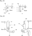
- FIG. 14 is an explanatory view illustrating the difference between the long length and the short length of each of the coil terminal 26 and intermediate terminal 43. As illustrated in FIG.
- the 26U on the coil terminal 26 side, the 26U has a long length, while the 26V and 26W have a short length; on the intermediate terminal 43 side, the 43V has a long length, while the 43U and 43W have a short length.
- the coil terminals 26U, 26V and 26W extend from the brushless motor 11 along the extending direction of the rotary shaft 31 with a different length. Then, the 26U (long length) and the 43U (short length) are connected at the terminal connection part 71U, the 26V (short length) and the 43V (long length) are connected at the terminal connection part 71V, and the 26W (short length) and the 43W (short length) are connected at the terminal connection part 71W.
- the long male terminal 26U is disposed at the near side (upper side), and the short male terminals 26V and 26W are disposed at the far side (lower side: the side of the bottom surface 1b of the frame 17) when viewed from the frame 17 side.
- a process of connecting the coil terminals 26 and intermediate terminals 43 is considered. First, the 26U having a larger extending length and its corresponding 43U are connected. That is, the long male terminal 26U is connected to the 43U before other short male terminals are connected to their corresponding terminals.
- the long terminal is more likely to undergo positional deviation at its leading end position than the short terminal, and it is not easy to perform connection of the plurality of terminals without any trouble in a state where long and short terminals coexist. Further, when a plurality of terminals having the same length exist, they may be erroneously assembled.
- the long male terminal 26U positioned at the near side is connected first, and then the short male terminals 26V and 26W positioned at the far side are connected.
- the terminal connection work it is possible to perform connection of the short male terminals 26V and 26W while confirming the insertion state of the long male terminal 26U.
- whether the insertion of the long male terminal is completed can be easily visually confirmed and, thereafter, the short male terminal can be connected reliably, whereby it is possible to prevent bending of the terminal and erroneous assembly between the terminals.
- the number of the terminal mounting parts 52 may be reduced to two by connecting two phases in a single terminal mounting part.
- the shape of the coil terminal 26 is not limited to that described above and, for example, as illustrated in FIG. 16 , the insertion part 61 and the hook part 62 may extend in the same direction.
- the stator 12, including the coil terminals 26 needs to satisfy the size requirement of the width Wd across flats.
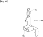
- the intermediate terminal 43 is soldered to the control board 42; however, the intermediate terminal 65 as illustrated in FIG. 17 and the control board 42 may be connected by press-fitting. Specifically, in this case, the control board 42 is fitted to the cover 18, and then the cover 18 is fitted to the frame 17. At this timing, the intermediate terminal 65 and the control board 42 are connected by press-fitting.
- the number of tooth parts/slots in the brushless motor 11 is illustrative only and not limited to six.
- IN/OUT in the winding order may be reversed.
- the winding order between the three-phases (U, V, W) may be arbitrarily determined and, for example, the winding order may be U ⁇ W ⁇ V in the counterclockwise direction.
- a combination of the three phases (U, V, W) at the terminal connection part 71 is not limited to that described above and may be arbitrarily determined.
- the present invention may be widely applied, in addition to the sunroof motor, to an on-vehicle motor used as a drive source for, e.g., a power window, a slide door, a rear gate, or an oil pump, various electric appliances such as home electric appliances, or industrial equipment such as a robot or an electric machine.
- an on-vehicle motor used as a drive source for, e.g., a power window, a slide door, a rear gate, or an oil pump
- various electric appliances such as home electric appliances, or industrial equipment such as a robot or an electric machine.
Landscapes
- Engineering & Computer Science (AREA)
- Power Engineering (AREA)
- Insulation, Fastening Of Motor, Generator Windings (AREA)
- Motor Or Generator Frames (AREA)
Abstract
Description
- The present invention relates to a brushless motor and, more particularly, to arrangement and position of coil terminals of the brushless motor and a mounting part structure thereof.
- Typically, in an inner-rotor type brushless motor, a stator around which coils are wound is disposed in a steel yoke, and a rotor having a magnet is rotatably provided inside the stator. An insulator is provided on the stator side as a component for insulation between a stator core and the coils as in
Patent Document 1. Each coil is wound around tooth of the stator core through the insulator. For electrical connection of the coils, the stator is attached with components called a terminal holder and a bus bar (see patent Document 2). Each coil wound around the tooth is electrically connected to an external power supply or a controller through the terminal holder and bus bar. -
- Patent Document 1:
JP 2013-38949A - Patent Document 2: International Publication
WO 2008/050637 - Patent Document 3:
JP 2013-70577A - However, in a conventional brushless motor using the terminal holder and bus bar, an insulating member (insulator) and an electrical connection component (terminal holder or bus bar) are formed separately, which disadvantageously increases the number of components and the number of processes/man-hours for assembly. When the electrical connection components are used, after winding is made around the stator core, it is necessary to perform winding connection for each phase by using the terminal holder and to connect the coils by using the bus bar. That is, "winding process → electrical connection component assembly process → winding connection process → fusing or TIG welding process" need to be performed. Thus, the number of assembly processes is disadvantageously increased in a stator formation process, resulting in deterioration in productivity.
- The stator can be formed without use of the above electrical connection components; in this case, however, the coil needs to be wound with a single stroke as in
Patent Document 3. However, in general, for the single-stroke winding, one portion largely protruding from the outer periphery of the stator core is formed as an area where an electrical connection terminal is provided. In the presence of such a protruding portion, it is difficult to satisfy size requirements in a compact-type motor disposed in a narrow space, such as a sunroof motor. - A brushless motor according to the present invention is a three-phase driven brushless motor including: a yoke formed of a magnetic material; a stator disposed in the yoke and having a coil obtained by winding a winding; and a rotor having a magnet and rotatably disposed in the stator. Flat surface parts which are two parallel opposing surfaces and connection parts provided at both sides of the flat surface parts and connecting the flat surface parts are formed in the outer periphery of the yoke. The stator has an insulator having three coil connection terminals connected with the winding. One of the three coil connection terminals is disposed on one connection part side with respect to the flat surface parts and the remaining two coil connection terminals are disposed on the other connection part side with respect to the flat surface parts. In this case, one of the coil connection terminals may be disposed at a position not adjacent to other coil connection terminals.
- In the brushless motor according to the present invention, a terminal holder-integrated insulator provided with the coil connection terminals is used, and the three coil connection terminals are not disposed on a yoke flat surface part but distributed to the connection part side. This allows reduction in size/thickness of the brushless motor to make it possible to reduce the width across flats (distance between the flat surface parts) of the motor. Further, a single-stroke winding is enabled with a small number of crossovers.
- The insulator may have coil winding parts around each of which the winding is wound and terminal mounting parts each mounted with the coil connection terminal. The terminal mounting parts may be disposed radially outside the coil winding parts. This eliminates the need for a nozzle for coil winding to perform "operation for avoiding the terminal", facilitating the winding work. Further, a guide part for guiding the winding may be formed radially outside the coil winding part behind which the terminal mounting part is absent.
- The coil connection terminal may have an insertion part inserted into a terminal insertion hole formed in the terminal mounting part, a hook part connected with the winding, and an intermediate part connecting the hook part and the insertion part. The terminal mounting part may have a terminal guide part formed in the vicinity of the terminal insertion hole and holding the intermediate part of the coil connection terminal abutting thereagainst. With this arrangement, even when a tensile force is applied to the hook part, movement of the intermediate part is restricted, so that the intermediate part is prevented from being bent by the tensile force.
- The winding may be wound/routed, starting from the coil connection terminal of a first phase disposed on the one connection part side, to a first-phase first coil existing at a position corresponding to the first-phase coil connection terminal, a first-phase second coil positioned opposite to the first-phase first coil, a second-phase first coil adjacent to the first-phase second coil, a second-phase second coil opposite to the second-phase first coil, a third-phase first coil adjacent to the second-phase second coil, and a third-phase second coil opposite to the third-phase first coil. In this case, the winding may be connected to the coil connection terminal of a second phase between the first-phase second coil and the second-phase first coil, connected to the coil connection terminal of a third phase between the second-phase second coil and the third-phase first coil, and connected to the first-phase coil connection terminal at the rear stage of the third-phase second coil. This enables a single stroke winding with a small number of crossovers.
- A motor with a speed reduction mechanism according to the present invention is a motor with a speed reduction mechanism using the above-described brushless motor including: a frame mounted with the brushless motor and accommodating therein a speed reduction mechanism and a control circuit, the speed reduction mechanism being connected to a rotary shaft of the brushless motor, speed-reducing rotation of the rotary shaft, and outputting the speed-reduced rotation to an output shaft, the control circuit being provided for controlling drive of the brushless motor; and three intermediate terminals fitted to the frame and each having one end electrically connected to the coil connection terminal and the other end electrically connected to the control circuit. Two of the three intermediate terminals are disposed so as to overlap each other in the vertical direction as viewed in the extending direction of the output shaft. In this case, two of the three intermediate terminals may be coaxially arranged on a first axis perpendicular to the rotary shaft, and another pair of the terminals may be coaxially arranged on a second axis perpendicular to the first axis.
- In the present invention, when the intermediate terminals are disposed in the manner as described above, the layout area of the terminal connection parts is finely arranged as compared to a case where the three connection parts between the intermediate terminals and the coil connection terminals are arranged at random, whereby the terminal connection parts can be efficiently laid out.
- In the motor with speed reduction mechanism, the two coil connection terminals disposed on the other connection part side with respect to the flat surface parts may extend along the extending direction of the rotary shaft of the brushless motor from the end portion of the brushless motor with different lengths, and a shorter one of the two coil connection terminals having different extending lengths may be disposed closer to the bottom surface side of the frame than the longer one is. Thus, a longer coil connection terminal at the near side (upper side) of an operator is first connected, and thereafter a short coil connection terminal disposed at the far side (lower side) is connected. As a result, in the terminal connection work, it is possible to perform connection of the shorter coil connection terminal while confirming the insertion state of the longer coil connection terminal, whereby it is possible to prevent erroneous assembly.
- Further, the frame may have a terminal holding part that holds the intermediate terminal and a bearing holding part that holds a bearing that rotatably supports the rotary shaft of the brushless motor. The terminal holding part and the bearing holding part may be disposed so as to be deviated from each other in the rotary shaft direction. As a result, both the terminal holding part and the bearing holding part can be formed in a thick solid portion, increasing rigidity and durability of the frame.
- According to the brushless motor of the present invention, a terminal holder-integrated insulator provided with the coil connection terminals is used, and the three coil connection terminals are not disposed on a yoke flat surface part but distributed to the connection part side. This allows reduction in size/thickness of the brushless motor.
- According to the motor with speed reduction mechanism of the present invention, two pairs of the three intermediate terminals are arranged in a line so as to overlap in the vertical and lateral directions, respectively as viewed from the frame side. Thus, as compared to a case where the three connection parts between the intermediate terminals and the coil connection terminals are arranged at random, the terminal connection parts can be efficiently laid out.
-
-
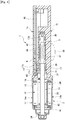
FIG. 1 is an explanatory view illustrating the configuration of a motor unit with a speed reduction mechanism using a brushless motor according to an embodiment of the present invention; -
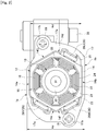
FIG. 2 is a side view of the brushless motor ofFIG. 1 as viewed in the axial direction thereof; -
FIG. 3 is an explanatory view illustrating the configuration of a stator in the brushless motor; -
FIG. 4 is an explanatory view illustrating the configuration of a terminal mounting part in an insulator; -
FIG. 5 is an explanatory view illustrating the terminal mounting part as viewed in the direction of the arrow P ofFIG. 4 ; -
FIG. 6 is a perspective view illustrating the configuration of a coil terminal; -
FIG. 7 is a coil connection diagram; -
FIG. 8 is an explanatory view illustrating a coil winding state; -
FIG. 9 is a developed coil winding diagram; -
FIG. 10 is an explanatory view illustrating a winding state of the last coil to be subjected to winding work; -
FIG. 11 is an explanatory view illustrating a state where a winding is hooked to a pole provided in the vicinity of a terminal mounting part of the insulator; -
FIG. 12 is an explanatory view illustrating the connection configuration between the coil terminal and an intermediate terminal; -
FIG. 13 (a) is an explanatory view illustrating the positions of terminal connection parts in the motor unit according to the present invention;FIG. 13(b) is an explanatory view illustrating a state where three terminal connection parts are disposed at random; -
FIG. 14 is an explanatory view illustrating the difference between long size and short size of each of the coil terminal and the intermediate terminal; -
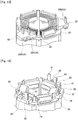
FIG. 15 is an explanatory view illustrating a modification in which the number of terminal mounting parts is reduced to two; -
FIG. 16 is an explanatory view illustrating a modification using a coil terminal in which an insertion part and a hook part extend in the same direction; and -
FIG. 17 is an explanatory view illustrating a configuration of the intermediate terminal where the intermediate terminal and the control board are connected by press-fitting. - Hereinafter, an embodiment of the present invention will be described in detail based on the drawings. An object of the present embodiment is to provide a slim-type brushless motor excellent in productivity. Another object of the present embodiment is to provide a motor with a speed reduction mechanism using a brushless motor, in which terminals connecting a motor side and a control part side are arranged with high space efficiency.
-
FIG. 1 is an explanatory view illustrating the configuration of amotor unit 1 with a speed reduction mechanism using abrushless motor 11 according to an embodiment of the present invention.FIG. 2 is a side view of thebrushless motor 11 as viewed in the axial direction thereof. Themotor unit 1 ofFIG. 1 is an electromechanically integrated motor with a speed reduction mechanism in which a motor and a control part are integrated. Themotor unit 1 includes amotor part 2 having thebrushless motor 11, a speedreduction mechanism part 3 using a worm gear, and acontrol part 4 mounted with a control circuit for controlling drive of thebrushless motor 11. Themotor unit 1 is used for a drive source of, e.g., an electrical sunroof of a car. - The
brushless motor 11 is provided in themotor part 2. Thebrushless motor 11 is an inner-rotor type brushless motor in which astator 12 is provided outside arotor 13. Thestator 12 has amotor case 14 serving also as a yoke, a stator core (core member) 15 fixed to the inner peripheral side of themotor case 14, and coils 16 wound around thestator core 15. Themotor case 14 is made of iron and formed into a bottomed cylindrical shape with a hexagonal cross section. An opening part of themotor case 14 is attached with aframe 17 made of synthetic resin. The upper part of theframe 17 is opened, and acover 18 is fitted to the opening part. Themotor case 14 is fixed by way ofscrews 19 fit into motor mountingscrew holes 17b. The screw holes 17b are formed inflange parts 17a of theframe 17. - The
stator core 15 has an integrated core structure in which a number of steel plates are laminated. Thestator core 15 has ahexagonal yoke part 21 and atooth part 22 formed so as to protrude inward from theyoke part 21. Thetooth part 22 is provided in plural numbers (six, in this example) in the peripheral direction. A slot 23 (six, in this example) is formed between theadjacent tooth parts 22. Aninsulator 24 made of synthetic resin is fitted to the inner side of thestator core 15 from both end sides in the axial direction. A winding 25 is wound around each tooth part through theinsulator 24 to thereby form acoil 16. Theinsulator 24 is provided with a coil terminal (coil connection terminal) 26 (26U, 26V, 26W) corresponding to each phase (three phases of U, V, and W, in this example). The coils 16 (windings 25) are electrically connected to theircorresponding coil terminals - The
rotor 13 is disposed inside thestator 12. Therotor 13 has a configuration in which arotary shaft 31, arotor core 32, and amagnet 33 are coaxially disposed. A cylindrical-shapedrotor core 32 obtained by laminating a number of steel plates is fitted to the outer periphery of therotary shaft 31. Amagnet 33 magnetized to a plurality of poles along the peripheral direction is fixed to the outer periphery of therotor core 32. One end portion of therotary shaft 31 is rotatably supported by abearing 34. Thebearing 34 is press-fitted to the bottom part of themotor case 14. The other end portion of therotary shaft 31 is rotatably supported by bearingmetals metals parts 17c and 17d, respectively. - A
worm 37 is formed at the end portion (right end portion inFIG. 1 ) of therotary shaft 31. Theworm 37 is engaged with aworm wheel 38 disposed inside theframe 17. Theworm 37 andworm wheel 38 constitute a speedreduction mechanism part 3. Theworm wheel 38 is fitted to anoutput shaft 39. In themotor unit 1, rotation of therotary shaft 31 of thebrushless motor 11 is speed-reduced by the speedreduction mechanism part 3 and transmitted to theoutput shaft 39, whereby theoutput shaft 39 is driven into rotation. - A
sensor magnet 41 for detecting rotation of therotor 13 is fitted to therotary shaft 31. Thesensor magnet 41 is magnetized to a plurality of poles along the peripheral direction. Non-illustrated Hall ICs (magnetism detection elements) are provided in theframe 17 so as to be opposed to the magnetic poles of thesensor magnet 41. The Hall IC is mounted on acontrol board 42 of thecontrol part 4. In addition to the Hall IC, thecontrol board 42 is mounted with elements such as a control IC, a resistor, and a capacitor. Thecontrol board 42 and thebrushless motor 11 are electrically connected by an intermediate terminal (board connection terminal) 43. Theintermediate terminal 43 is press-fixed to aterminal holding part 17e of theframe 17. Theterminal holding part 17e is located at a position axially deviated from the bearing holding part 17c so that theterminal holding part 17e and the bearing holding part 17c do not axially overlap each other. As a result, both theterminal holding part 17e and the bearing holding part 17c can be formed in a thick solid portion, increasing rigidity and durability of theframe 17, which allows improvement in reliability and increase in output. - In the
motor unit 1, by fitting theinsulator 24 to thestator core 15, a stator assembly in which thecoils 16 are wound/wired on theinsulator 24 is formed. Then, the stator assembly is press-fitted to theframe 17, whereby the coil terminal 26 (26U, 26V, 26W) of thebrushless motor 11 and one end side of the intermediate terminal 43 (43U, 43V, 43W; seeFIG. 12 ) are fitted and electrically connected to each other. At this time, a load applied to theintermediate terminal 43 due to connection between the terminals is received by theterminal holding part 17e. After connection of theterminals 26 and 44, thecontrol board 42 is assembled to theframe 17 and soldered to the other end side (board connection part 43a) of theintermediate terminal 43. As a result, thecontrol board 42 and thebrushless motor 11 are electrically connected, allowing thecontrol part 4 to control drive of thebrushless motor 11. - The
brushless motor 11 according to the present invention has features different from those of conventional brushless motors in the following points. - (1) Arrangement of coil terminals of stator
- (2) Coil terminal position
- (3) Coil terminal mounting part structure in insulator
- (4) Coil winding order
- (5) Arrangement of intermediate terminals
- Below is given an explanation of the above-listed features.
- As illustrated in
FIG. 2 , in thebrushless motor 11, three-phase coil terminals motor unit 1. Themotor unit 1 is used under conditions where the installation width (height) is restricted, as a sunroof motor is. Thus, in order to satisfy size requirements for the sunroof motor, thecoil terminals 26 are provided so as not to protrude from the width across flats. - The
motor case 14 of thebrushless motor 11 has top and bottom surfaces (flat surface parts) 14a, 14b and side surfaces (connection parts) 14c, 14d, 14e, 14f. The top andbottom surfaces FIGS. 1 and2 ) 1a and 1b extending perpendicular to theoutput shaft 39 of themotor unit 1. The side surfaces 14c, 14d, 14e, and 14f are disposed in the vertical direction so as to connect the top andbottom surfaces bottom surfaces output shaft 39. Thebrushless motor 11, including thecoil terminals 26, needs to be accommodated within a space defined by a value regulated by the width Wd across flats. - Thus, in the
brushless motor 11 according to the present invention, thecoil terminals 26 are disposed so as to be distributed to a portion (right side portion inFIG. 2 ) corresponding to the side surfaces 14c and 14d on one side of the top andbottom surfaces FIG. 2 ) corresponding to the side surfaces 14e and 14f on the other side of the top andbottom surfaces coil terminal 26U) and a plurality of coil terminals 26 (e.g.,coil terminals side surface 14d on the one side) and the other side (to the side surfaces 14e and 14f on the other side), respectively, with nocoil terminal 26 on the top andbottom surfaces - Thus, at least one of the three-
phase coil terminals coil terminal 26. Further, thecoil terminals flange part 17a side at which the screw holes 17b are formed. Further, thecoil terminals coil terminal 26 on the side close to the top andbottom surfaces stator core 15. As a result, the outer diameter of thebrushless motor 11 can fall within the width Wd across flats, whereby it is possible to reduce size and thickness of the motor according to motor size requirements. - The three-
phase coil terminals coil terminal 26 protruding from thestator core 15 in the radial direction. That is, the protruding area per coil terminal is reduced to thereby make it possible to increase the consecutive section modulus of theinsulator 24 and, correspondingly, the rigidity of theinsulator 24 can be enhanced. Further, the reduction in the protruding area of theinsulator 24 per coil terminal allows increase in the thickness of theframe 17 to which the stator assembly is assembled, which in turn can enhance the rigidity of theframe 17. - In the
brushless motor 11, the three-phase coil terminals coils 16. In this case, there is no dimensional margin behind the coil on the sides of the top andbottom surfaces coil terminal 26 is disposed at three of four positions corresponding to the side surfaces 14c, 14d, 14e and 14f.FIG. 3 is an explanatory view of the configuration of thestator 12 in thebrushless motor 11, which illustrates thecoil terminal 26 and a winding state of thecoil 16. - As illustrated in
FIG. 3 , theinsulator 24 is provided with acoil winding part 51 around which thecoil 16 is wound and aterminal mounting part 52 to which thecoil terminal 26 is mounted. Theinsulator 24 has an insulating function and a function of retaining thecoil terminal 26, and thebrushless motor 11 adopts an "insulator/terminal holder integrated" configuration. The integration of the insulator and terminal holder eliminates the need of assembling an electrical connection component. This allows reduction in assembling man-hours and the number of components and further allows reduction in assembling dimensional error of the coil terminal. - Three
terminal mounting parts 52 are formed behind, i.e., radially outside their correspondingcoil winding parts 51. A wall-shapedcoil guide part 53 is formed behind thecoil winding part 51 behind which theterminal mounting part 52 is absent. Disposing thecoil terminal 26 radially outside thecoil 16 eliminates the need for a nozzle for coil winding to perform "operation for avoiding the terminal" at the time of winding thecoil 16. As a result, a winding work is made efficient, thereby making it possible to reduce production man-hours for the stator. -
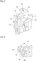
FIG. 4 is an explanatory view illustrating the configuration of theterminal mounting part 52 in theinsulator 24, andFIG. 5 is an explanatory view illustrating theterminal mounting part 52 as viewed in the direction of the arrow P ofFIG. 4 .FIG. 6 is a perspective view illustrating the configuration of thecoil terminal 26. As illustrated inFIG. 4 , aterminal insertion hole 54 through which thecoil terminal 26 is inserted is formed in theterminal mounting part 52. Thecoil terminal 26 is inserted from below ofFig. 4 into theterminal insertion hole 54. Thecoil terminal 26 is a male terminal and is constituted of aninsertion part 61 to be inserted into theterminal insertion hole 54, ahook part 62 connected with thecoil 16, and anintermediate part 63 connecting thehook part 62 and theinsertion part 61, as illustrated inFIG. 6 . Theinsertion part 61 has anengagement pawl 64. When theinsertion part 61 is inserted into theterminal insertion hole 54, the tip end of theengagement pawl 64 is engaged with aterminal holding part 55 formed in theterminal mounting part 52 so as to protrude, whereby thecoil terminal 26 is fixed to and prevented from coming off theterminal mounting part 52. - As illustrated in
FIG. 5 , arib 56 extending from the insulator body side is formed at the back side (indicated by the arrow P) of theterminal mounting part 52. Abottom surface 56a of therib 56 abuts against the end face of thestator core 15. Thecoil terminal 26 is fitted to theintermediate terminal 43 when thebrushless motor 11 is assembled to theframe 17 and, at this time, receives a load from theintermediate terminal 43 side. Therib 56 is provided for receiving the insertion load, and theterminal mounting part 52 is supported by therib 56 when the terminals are connected to each other. Thus, theterminal mounting part 52 is enhanced in rigidity and is thus unlikely to be deformed even when receiving the insertion load through theengagement pawl 64. This facilitates the connection work between thecoil terminal 26 and theintermediate terminal 43 and prevents breakage of theterminal mounting part 52 due to the insertion load, resulting in improvement in reliability. - The
terminal mounting part 52 further has aterminal guide part 57 for holding theintermediate part 63 of thecoil terminal 26. As illustrated inFIGS. 4 and 5 , theterminal guide part 57 is formed in the vicinity of the lower end of theterminal insertion hole 54 so as to face theterminal insertion hole 54. When thecoil terminal 26 is inserted into theterminal insertion hole 54, theterminal guide part 57 and aside surface 63a of theintermediate part 63 abut against each other. At coil winding, a tensile force is applied to thehook part 62 of thecoil terminal 26, and the terminal may be bent by the tensile force of the winding 25. On the other hand, in thebrushless motor 11 of the present invention, theintermediate part 63 connecting thehook part 62 and theinsertion part 61 is supported by theterminal guide part 57 of theinsulator 24, and movement of theintermediate part 63 is restricted. Thus, even when the tensile force is applied to thehook part 62, theintermediate part 63 is prevented from being pulled and bent by the tensile force, whereby yield and reliability of the product can be improved. - In addition, the
coil winding part 51 of theinsulator 24 has a windingpart 51a around which the winding 25 is wound and aflange part 51b formed on the inner diameter side of the windingpart 51a. A round chamferedcurved surface part 51c is formed in the corner portions of each of the windingpart 51a andflange part 51b as a clearance for a nozzle in consideration of the nozzle route at coil winding. Forming thecurved surface part 51c in the corner portions allows the nozzle to be operated at a position closer to the windingpart 51a to thereby reduce nozzle operation distance, which can increase a winding speed and reduce production man-hours. -
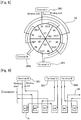
FIG. 7 is a connection diagram of thecoil 16,FIG. 8 is an explanatory view illustrating a winding state of thecoil 16, andFIG. 9 is a developed winding diagram of thecoil 16. As illustrated inFIG. 7 , thecoils 16 are delta-connected and are wound with a single stroke wherein winding for all the slots is completed between a winding start and a winding end. As illustrated inFIGS. 8 and 9 , the winding work is performed in the following order with thecoil terminal 26U provided alone to theside surface 14d on the one side as a starting point: - (a) A U-phase first coil U1 is wound from the
coil terminal 26U; - (b) After winding of the U1, a U-phase second coil U2 opposite to the U1 is wound with two
tooth parts 22 interposed therebetween; - (c) After winding of the U2, the winding 25 from the U2 is connected to the
coil terminal 26V, and then a V-phase first coil V1 adjacent to the U2 is wound; - (d) After winding of the V1, a V-phase second coil V2 opposite to the V1 is wound with two
tooth parts 22 interposed therebetween; - (e) After winding of the V2, the winding 25 from the V2 is connected to the
coil terminal 26W, and then a W-phase first coil W1 adjacent to the V2 is wound; - (f) After winding of the W1, a W-phase second coil W2 opposite to the W1 is wound with two
tooth parts 22 interposed therebetween; and - (g) After winding of the W2, the winding 25 is connected to the
coil terminal 26U adjacent to the W2. As illustrated inFIG. 10 , in the coil W2 which is the last coil to be subjected to the winding work, the entrance of the winding start and exit of the winding end are set at the same position in order to maintain the tensile force of the winding 25. - That is, in the
brushless motor 11, starting from the coil terminal existing alone, opposing same-phase coils 16 are wound ((b), (d), (f)), followed by adjacent different-phase coils ((c), (e)). As described above, in thebrushless motor 11 of the present invention, the terminal holder-integrated insulator is assembled to thestator core 15 having an integrated core structure, and thecoils 16 are wound with a single stroke and delta-connected, thus eliminating the need to perform an assembly process of an electrical connection component and winding connection processing. As a result, the number of processes for production can be reduced to thereby allow cost reduction. - As illustrated in
FIG. 11 , when the above winding connection is performed, the winding 25 is hooked to apole 58 provided in the vicinity of each terminal mountingpart 52 of theinsulator 24. By making the winding 25 be along thepole 58 during the single-stroke winding, a tensile force can be applied to the winding 25 when the winding 25 is locked to thehook part 62. This can enhance adhesion between thecoil terminal 26 and the winding 25, thereby making it possible to improve electric connectivity when, e.g., fusing is performed. - Further, in the winding process (d), when the winding 25 is routed from the V1 to V2, a
crossover 59 of the winding 25 strides over the U1 in which the winding has already been completed. Since thecoil terminal 26U exists radially outside the coil U1, the crossover cannot be routed behind the coil U1. Further, when the crossover exists before routing, the winding work of the coil U1 is very difficult to perform. On the other hand, according to the above-described winding process, the crossover is routed after coil formation, so that the winding work can be performed without any particular difficulty. Further, unlike a general single-stroke winding, there exists an area where the crossover passes in a chord shape over the coil in which the winding has already been completed, so that the length of the crossover can be reduced. At theother coil terminals crossover 59 does not pass behind the 26V and 26W but is hooked to thehook part 62 and routed toward theadjacent coil 16 on thehook part 62 side, so that no problem occurs as to the routing of the crossover. - In addition, in the
brushless motor 11, the number of overlappingcrossovers 59 is suppressed four at a maximum at the crossovers overlapping area. For example, in the motor disclosed inPatent Document 3, there exists an area where six crossovers overlap, complicating accommodation or routing of the winding 25. On the other hand, in thebrushless motor 11, the number of overlappingcrossovers 59 is four at a maximum, thus facilitating accommodation/holding of the crossover, so that it is possible to reduce the size/weight of the insulator. - As described above, in the
motor unit 1, thebrushless motor 11 and thecontrol board 42 are electrically connected by connecting thecoil terminal 26 and theintermediate terminal 43.FIG. 12 is an explanatory view illustrating the connection configuration between thecoil terminal 26 and theintermediate terminal 43, andFIG. 13 (a) is an explanatory view illustrating the positions of terminal connection parts 71 (71U, 71V, 71W) in themotor unit 1. At theterminal connection parts insertion parts 61 of therespective coil terminals fitting parts 43b of the respectiveintermediate terminals - In general, an electromechanically integrated motor unit with a speed reduction mechanism is provided with a motor-side terminal and a control board-side terminal, and the connection layout of the both terminals is an important element to determine the physical size or structure of the motor. In recent years, as to a sunroof motor, there has been a shift in terms of structure, from a brush motor to a brushless motor and, correspondingly, the number of connection portions between the terminals is increased from two to three. However, the size of a device frame cannot be enlarged despite the increase in the number of the terminals and, in such circumstances, it is very difficult for three terminals to be laid out in the present space.
- Thus, in the
motor unit 1 of the present invention, two of the three connection portions (71U, 71V, 71W) between the terminals are arranged so as to overlap each other in the vertical direction as viewed in the extending direction of theoutput shaft 39. That is, as illustrated inFIG. 13A , of theterminal connection parts motor rotary shaft 31 as viewed from thecontrol board 42 positioned above the terminals. Further, another pair of the terminals (71V and 71W) are coaxially arranged on an axis (axis Y: second axis) perpendicular (parallel to the rotary shaft 31) to the axis X. Further, when theterminal connection parts rotary shaft 31 from theframe 17 side, two pairs of the terminals (e.g., 71U and 71V, 71V and 71W inFig. 13 ) are arranged in a line so as to overlap in the vertical and lateral directions, respectively. - When the terminal connection parts 71 are thus arranged, both the number of X-coordinates and the number of Y-coordinates on the
control board 42 can be reduce to one. Thus, as compared to a case (FIG. 13B ) where the three connection parts are arranged at random, the layout area of the terminal connection parts 71 is finely arranged (in the case ofFIG. 13B , both the numbers of X-coordinates and the number of Y-coordinates are three). As a result, the connection parts between thecoil terminals 26 and theintermediate terminals 43 can be efficiently laid out in a small space, thereby facilitating production of thecontrol board 42 connected with theintermediate terminals 43. - Further, in the
motor unit 1, the relationship among the lengths of theinsertion parts 61 of therespective coil terminals intermediate terminals fitting parts 43b to the leading ends of theboard connection parts 43a are each represented by "long length × 1 and short length × 2".FIG. 14 is an explanatory view illustrating the difference between the long length and the short length of each of thecoil terminal 26 andintermediate terminal 43. As illustrated inFIG. 12 , in the present embodiment, on thecoil terminal 26 side, the 26U has a long length, while the 26V and 26W have a short length; on theintermediate terminal 43 side, the 43V has a long length, while the 43U and 43W have a short length. Thecoil terminals brushless motor 11 along the extending direction of therotary shaft 31 with a different length. Then, the 26U (long length) and the 43U (short length) are connected at theterminal connection part 71U, the 26V (short length) and the 43V (long length) are connected at theterminal connection part 71V, and the 26W (short length) and the 43W (short length) are connected at theterminal connection part 71W. - When the
coil terminals 26 andintermediate terminals 43 are arranged in such a manner, the long male terminal 26U is disposed at the near side (upper side), and theshort male terminals bottom surface 1b of the frame 17) when viewed from theframe 17 side. Here, a process of connecting thecoil terminals 26 andintermediate terminals 43 is considered. First, the 26U having a larger extending length and its corresponding 43U are connected. That is, the long male terminal 26U is connected to the 43U before other short male terminals are connected to their corresponding terminals. In general, the long terminal is more likely to undergo positional deviation at its leading end position than the short terminal, and it is not easy to perform connection of the plurality of terminals without any trouble in a state where long and short terminals coexist. Further, when a plurality of terminals having the same length exist, they may be erroneously assembled. - In the
motor unit 1 according to the present invention, when performing connection of theterminals 26 ad 44, the long male terminal 26U positioned at the near side is connected first, and then theshort male terminals short male terminals - The present invention is not limited to the above embodiment and may be variously modified without departing from the spirit of the invention.
- For example, in the above embodiment, three
terminal mounting parts 52 are provided; however, as illustrated inFIG. 15 , the number of theterminal mounting parts 52 may be reduced to two by connecting two phases in a single terminal mounting part. Further, the shape of thecoil terminal 26 is not limited to that described above and, for example, as illustrated inFIG. 16 , theinsertion part 61 and thehook part 62 may extend in the same direction. However, in the case ofFIGS. 15 and 16 as well, thestator 12, including thecoil terminals 26, needs to satisfy the size requirement of the width Wd across flats. - Further, in the above embodiment, the
intermediate terminal 43 is soldered to thecontrol board 42; however, theintermediate terminal 65 as illustrated inFIG. 17 and thecontrol board 42 may be connected by press-fitting. Specifically, in this case, thecontrol board 42 is fitted to thecover 18, and then thecover 18 is fitted to theframe 17. At this timing, theintermediate terminal 65 and thecontrol board 42 are connected by press-fitting. - In addition, the number of tooth parts/slots in the
brushless motor 11 is illustrative only and not limited to six. Further, IN/OUT in the winding order may be reversed. Similarly, the winding order between the three-phases (U, V, W) may be arbitrarily determined and, for example, the winding order may be U→W→V in the counterclockwise direction. Further, a combination of the three phases (U, V, W) at the terminal connection part 71 is not limited to that described above and may be arbitrarily determined. - The present invention may be widely applied, in addition to the sunroof motor, to an on-vehicle motor used as a drive source for, e.g., a power window, a slide door, a rear gate, or an oil pump, various electric appliances such as home electric appliances, or industrial equipment such as a robot or an electric machine.
-
- 1: Motor unit
- 1a: Top surface
- 1b: Bottom surface
- 2: Motor part
- 3: Speed reduction mechanism part
- 4: Control part
- 11: Brushless motor
- 12: Stator
- 13: Rotor
- 14: Motor case
- 14a: Top surface
- 14b: Bottom surface
- 14c to 14f: Side surface
- 15: Stator core
- 16: Coil
- 17: Frame
- 17a: Flange part
- 17b: Screw hole
- 17c: Bearing holding part
- 17d: Bearing holding part
- 17e: Terminal holding part
- 18: Cover
- 19: Screw
- 21: Yoke part
- 22: Tooth part
- 23: Slot
- 24: Insulator
- 25: Winding
- 26: Coil terminal (coil connection terminal)
- 26U, 26V, 26W: Coil terminal
- 31: Rotary shaft
- 32: Rotor core
- 33: Magnet
- 34: Bearing
- 35: Bearing metal
- 37: Worm
- 38: Worm wheel
- 39: Output shaft
- 41: Sensor magnet
- 42: Control board
- 43: Intermediate terminal
- 43U, 43V, 43W: Intermediate terminal
- 43a: Board connection part
- 43b: Fitting part
- 51: Coil winding part
- 51a: Winding part
- 51b: Flange part
- 51c: Curved surface part
- 52: Terminal mounting part
- 53: Coil guide part
- 54: Terminal insertion hole
- 55: Terminal holding part
- 56: Rib
- 56a: Bottom surface
- 57: Terminal guide part
- 58: Pole
- 59: Crossover
- 61: Insertion part
- 62: Hook part
- 63: Intermediate part
- 63a: Side surface
- 64: Engagement pawl
- 65: Intermediate terminal
- 71: Terminal connection part
- 71U, 71V, 71W: Terminal connection part
- U1: U-phase first coil
- U2: U-phase second coil
- V1: V-phase first coil
- V2: V-phase second coil
- W1: W-phase first coil
- W2: W-phase second coil
- Wd: Width across flats
- Wd': Width of stator core
Claims (12)
- A three-phase driven brushless motor characterized by comprising:a yoke formed of a magnetic material;a stator disposed in the yoke and having a coil obtained by winding a winding; anda rotor having a magnet and rotatably disposed in the stator, whereinflat surface parts which are two parallel opposing surfaces and connection parts provided at both sides of the flat surface parts and connecting the flat surface parts are formed in the outer periphery of the yoke,the stator has an insulator having three coil connection terminals connected with the winding,one of the three coil connection terminals is disposed on one connection part side with respect to the flat surface parts and the remaining two coil connection terminals are disposed on the other connection part side with respect to the flat surface parts.
- The brushless motor according to claim 1, characterized in that
one of the coil connection terminals is disposed at a position not adjacent to other coil connection terminals. - The brushless motor according to claim 1 or 2, characterized in that
the insulator has coil winding parts around each of which the winding is wound and terminal mounting parts each mounted with the coil connection terminal, and
the terminal mounting parts are disposed radially outside the coil winding parts. - The brushless motor according to claim 3, characterized in that
the terminal mounting parts are disposed radially outside the coil winding part, and
a guide part for guiding the winding is formed radially outside the coil winding part behind which the terminal mounting part is absent. - The brushless motor according to claim 3 or 4, characterized in that
the coil connection terminal has an insertion part inserted into a terminal insertion hole formed in the terminal mounting part, a hook part connected with the winding, and an intermediate part connecting the hook part and the insertion part, and
the terminal mounting part has a terminal guide part formed in the vicinity of the terminal insertion hole and holding the intermediate part of the coil connection terminal abutting thereagainst. - The brushless motor according to any one of claims 1 to 5, characterized in that
the winding includes, starting from the coil connection terminal of a first phase disposed on the one connection part side, a first-phase first coil existing at a position corresponding to the first-phase coil connection terminal, a first-phase second coil positioned opposite to the first-phase first coil, a second-phase first coil adjacent to the first-phase second coil, a second-phase second coil opposite to the second-phase first coil, a third-phase first coil adjacent to the second-phase second coil, and a third-phase second coil opposite to the third-phase first coil, and
the first-phase first coil, first-phase second coil, second-phase first coil, second-phase second coil, third-phase first coil, and third-phase second coil are formed continuously. - The brushless motor according to claim 6, characterized in that
the winding is connected to the coil connection terminal of a second phase between the first-phase second coil and the second-phase first coil, connected to the coil connection terminal of a third phase between the second-phase second coil and the third-phase first coil, and connected to the first-phase coil connection terminal at the rear stage of the third-phase second coil. - A motor with a speed reduction mechanism using the brushless motor as claimed in any one of claims 1 to 7, characterized by comprising:a frame mounted with the brushless motor and accommodating therein a speed reduction mechanism and a control circuit, the speed reduction mechanism being connected to a rotary shaft of the brushless motor, speed-reducing rotation of the rotary shaft, and outputting the speed-reduced rotation to an output shaft, the control circuit being provided for controlling drive of the brushless motor; andthree intermediate terminals fitted to the frame and each having one end electrically connected to the coil connection terminal and the other end electrically connected to the control circuit, whereintwo of the three intermediate terminals are disposed so as to overlap each other in the vertical direction as viewed in the extending direction of the output shaft.
- The motor with speed reduction mechanism according to claim 8, characterized in that
two of the three intermediate terminals are coaxially arranged on a first axis perpendicular to the rotary shaft, and another pair of the terminals are coaxially arranged on a second axis perpendicular to the first axis. - The motor with speed reduction mechanism according to claim 8, characterized in that
two of the three intermediate terminals are coaxially arranged on a first axis perpendicular to the rotary shaft of the brushless motor, and another pair of the terminals are coaxially arranged on a second axis perpendicular to the first axis. - The motor with speed reduction mechanism according to any one of claims 8 to 10, characterized in that
the two coil connection terminals disposed on the other connection part side with respect to the flat surface parts extend along the extending direction of the rotary shaft of the brushless motor from the end portion of the brushless motor with different lengths, and
a shorter one of the two coil connection terminals having different extending lengths is disposed closer to the bottom surface side of the frame than the longer one is. - The motor with speed reduction mechanism according to any one of claims 8 to 11, characterized in that
the frame has a terminal holding part that holds the intermediate terminal and a bearing holding part that holds a bearing that rotatably supports the rotary shaft of the brushless motor, and
the terminal holding part and bearing holding part are disposed so as to be deviated from each other in the rotary shaft direction.
Applications Claiming Priority (2)
| Application Number | Priority Date | Filing Date | Title |
|---|---|---|---|
| JP2016005730A JP6629078B2 (en) | 2016-01-15 | 2016-01-15 | Motor with reduction mechanism |
| PCT/JP2017/000971 WO2017122766A1 (en) | 2016-01-15 | 2017-01-13 | Brushless motor and motor with speed reduction mechanism |
Publications (3)
| Publication Number | Publication Date |
|---|---|
| EP3404805A1 true EP3404805A1 (en) | 2018-11-21 |
| EP3404805A4 EP3404805A4 (en) | 2019-08-07 |
| EP3404805B1 EP3404805B1 (en) | 2023-10-25 |
Family
ID=59311627
Family Applications (1)
| Application Number | Title | Priority Date | Filing Date |
|---|---|---|---|
| EP17738518.4A Active EP3404805B1 (en) | 2016-01-15 | 2017-01-13 | Brushless motor and motor with speed reduction mechanism |
Country Status (4)
| Country | Link |
|---|---|
| EP (1) | EP3404805B1 (en) |
| JP (1) | JP6629078B2 (en) |
| CN (1) | CN108475954B (en) |
| WO (1) | WO2017122766A1 (en) |
Cited By (2)
| Publication number | Priority date | Publication date | Assignee | Title |
|---|---|---|---|---|
| US11837935B2 (en) | 2021-02-02 | 2023-12-05 | Black & Decker, Inc. | Canned brushless motor |
| US12126235B2 (en) | 2020-03-25 | 2024-10-22 | Nidec Corporation | Motor |
Families Citing this family (13)
| Publication number | Priority date | Publication date | Assignee | Title |
|---|---|---|---|---|
| US11165313B2 (en) | 2017-08-01 | 2021-11-02 | Mabuchi Motor Co., Ltd. | Decelerator-equipped motor unit |
| JP6994873B2 (en) * | 2017-08-29 | 2022-01-14 | 株式会社ミツバ | Brushless motor |
| JP6616367B2 (en) * | 2017-09-13 | 2019-12-04 | シナノケンシ株式会社 | motor |
| JP2019103211A (en) * | 2017-11-30 | 2019-06-24 | 工機ホールディングス株式会社 | Motor and power tool using the same |
| JP6948274B2 (en) * | 2018-02-15 | 2021-10-13 | 東芝ライフスタイル株式会社 | Electric blower and vacuum cleaner |
| JP7037868B2 (en) * | 2018-03-27 | 2022-03-17 | 株式会社山田製作所 | Motor stator |
| WO2020095711A1 (en) * | 2018-11-07 | 2020-05-14 | デンソートリム株式会社 | Rotating electrical machine terminal, rotating electrical machine, and method for manufacturing rotating electrical machine |
| CN110417162B (en) * | 2019-08-08 | 2024-06-21 | 深圳南方德尔汽车电子有限公司 | Double-stator brushless motor |
| JP7403308B2 (en) * | 2019-12-16 | 2023-12-22 | ミネベアミツミ株式会社 | motor |
| JP7539106B2 (en) * | 2020-03-26 | 2024-08-23 | パナソニックIpマネジメント株式会社 | Brushless motors and power tools |
| KR102589929B1 (en) * | 2020-12-03 | 2023-10-17 | 주식회사 현대케피코 | Motor assembly structure for fuel cell vehicle |
| EP4274065A3 (en) | 2022-01-24 | 2023-11-15 | Techtronic Cordless GP | Electrical interconnector and motor including the same |
| JP7807346B2 (en) | 2022-09-08 | 2026-01-27 | 株式会社ミツバ | Brushless motor |
Family Cites Families (13)
| Publication number | Priority date | Publication date | Assignee | Title |
|---|---|---|---|---|
| JPS57133265U (en) * | 1981-02-13 | 1982-08-19 | ||
| JPH051970Y2 (en) * | 1986-09-18 | 1993-01-19 | ||
| JPH09215248A (en) * | 1996-01-30 | 1997-08-15 | Fanuc Ltd | Synchronous motor stator structure |
| US6227822B1 (en) * | 1998-10-20 | 2001-05-08 | Lakewood Engineering And Manufacturing Co. | Fan with improved electric motor and mounting |
| JP2001103698A (en) * | 1999-09-30 | 2001-04-13 | Aisin Seiki Co Ltd | Motor stator |
| US8450898B2 (en) * | 2006-09-01 | 2013-05-28 | Resmed Motor Technologies Inc | Insulator for stator assembly of brushless DC motor |
| JP2008131682A (en) * | 2006-11-16 | 2008-06-05 | Fujitsu General Ltd | Axial air gap type electric motor |
| JP4901819B2 (en) * | 2008-07-16 | 2012-03-21 | 三菱電機株式会社 | Mold stator, pump, water heater, electric motor, and air conditioner |
| JP2010093977A (en) * | 2008-10-09 | 2010-04-22 | Asmo Co Ltd | Motor with speed reduction mechanism |
| JP5435286B2 (en) * | 2009-06-24 | 2014-03-05 | 株式会社デンソー | Drive device |
| CN102280986B (en) * | 2010-06-11 | 2014-07-02 | 日本电产伺服有限公司 | rotating electrical machine |
| CN203951281U (en) * | 2011-05-24 | 2014-11-19 | 西门子公司 | There is the electric motor of self-support type housing |
| JP6190712B2 (en) * | 2013-12-13 | 2017-08-30 | 日本電産サンキョー株式会社 | motor |
-
2016
- 2016-01-15 JP JP2016005730A patent/JP6629078B2/en active Active
-
2017
- 2017-01-13 EP EP17738518.4A patent/EP3404805B1/en active Active
- 2017-01-13 CN CN201780006650.9A patent/CN108475954B/en active Active
- 2017-01-13 WO PCT/JP2017/000971 patent/WO2017122766A1/en not_active Ceased
Cited By (7)
| Publication number | Priority date | Publication date | Assignee | Title |
|---|---|---|---|---|
| US12126235B2 (en) | 2020-03-25 | 2024-10-22 | Nidec Corporation | Motor |
| US11837935B2 (en) | 2021-02-02 | 2023-12-05 | Black & Decker, Inc. | Canned brushless motor |
| US11855521B2 (en) | 2021-02-02 | 2023-12-26 | Black & Decker, Inc. | Brushless DC motor for a body-grip power tool |
| US11870316B2 (en) | 2021-02-02 | 2024-01-09 | Black & Decker, Inc. | Brushless motor including a nested bearing bridge |
| US11876424B2 (en) | 2021-02-02 | 2024-01-16 | Black & Decker Inc. | Compact brushless motor including in-line terminals |
| US11955863B2 (en) | 2021-02-02 | 2024-04-09 | Black & Decker Inc. | Circuit board assembly for compact brushless motor |
| US12261497B2 (en) | 2021-02-02 | 2025-03-25 | Black & Decker Inc. | High-power motor for a body-grip power tool |
Also Published As
| Publication number | Publication date |
|---|---|
| JP6629078B2 (en) | 2020-01-15 |
| EP3404805A4 (en) | 2019-08-07 |
| JP2017127146A (en) | 2017-07-20 |
| CN108475954A (en) | 2018-08-31 |
| CN108475954B (en) | 2020-04-28 |
| WO2017122766A1 (en) | 2017-07-20 |
| EP3404805B1 (en) | 2023-10-25 |
Similar Documents
| Publication | Publication Date | Title |
|---|---|---|
| EP3404805B1 (en) | Brushless motor and motor with speed reduction mechanism | |
| CN111052554B (en) | Motor insulators and brushless motors | |
| JP4743167B2 (en) | Terminal module for rotating electric machine and rotating electric machine | |
| EP2940834B1 (en) | Motor | |
| US10211699B2 (en) | Motor and bus bar unit having overlapping bridge portions | |
| CN103947088B (en) | Electric rotating machine | |
| EP3154162A1 (en) | Terminal block connection structure in rotary electric machine | |
| US20090039720A1 (en) | Terminal module for rotating electric machine, and rotating electric machine | |
| KR102388468B1 (en) | Stator and motor using the same | |
| JP2010130803A (en) | Polyphase ac motor and electric power steering apparatus | |
| EP3200318A1 (en) | Brushless motor | |
| DE102010017521A1 (en) | engine | |
| JPWO2015097753A1 (en) | Rotating electric machine | |
| US12489330B2 (en) | Coil winding portion structure for stator | |
| JP2005020851A (en) | Device for processing lead wire of motor | |
| CN103715788B (en) | The stator of electric motor and electric motor | |
| JP2010011601A (en) | Terminal unit for electric motor | |
| CN114915054B (en) | Stator and busbar modules | |
| CN110741537B (en) | Rotary motor | |
| JP2013247715A (en) | Stator and motor | |
| CN111194518B (en) | Electric power steering apparatus | |
| JP3902219B1 (en) | Centralized power distribution parts | |
| JP2009284679A (en) | Brushless motor | |
| CN112202264A (en) | Motor and compressor | |
| JP5203835B2 (en) | Lead wire fixing method and lead wire fixing structure |
Legal Events
| Date | Code | Title | Description |
|---|---|---|---|
| STAA | Information on the status of an ep patent application or granted ep patent |
Free format text: STATUS: THE INTERNATIONAL PUBLICATION HAS BEEN MADE |
|
| PUAI | Public reference made under article 153(3) epc to a published international application that has entered the european phase |
Free format text: ORIGINAL CODE: 0009012 |
|
| STAA | Information on the status of an ep patent application or granted ep patent |
Free format text: STATUS: REQUEST FOR EXAMINATION WAS MADE |
|
| 17P | Request for examination filed |
Effective date: 20180615 |
|
| AK | Designated contracting states |
Kind code of ref document: A1 Designated state(s): AL AT BE BG CH CY CZ DE DK EE ES FI FR GB GR HR HU IE IS IT LI LT LU LV MC MK MT NL NO PL PT RO RS SE SI SK SM TR |
|
| AX | Request for extension of the european patent |
Extension state: BA ME |
|
| DAV | Request for validation of the european patent (deleted) | ||
| DAX | Request for extension of the european patent (deleted) | ||
| A4 | Supplementary search report drawn up and despatched |
Effective date: 20190704 |
|
| RIC1 | Information provided on ipc code assigned before grant |
Ipc: H02K 3/52 20060101ALI20190628BHEP Ipc: H02K 7/116 20060101ALI20190628BHEP Ipc: H02K 3/28 20060101ALI20190628BHEP Ipc: H02K 5/22 20060101ALI20190628BHEP Ipc: H02K 3/46 20060101AFI20190628BHEP Ipc: H02K 11/30 20160101ALI20190628BHEP |
|
| STAA | Information on the status of an ep patent application or granted ep patent |
Free format text: STATUS: EXAMINATION IS IN PROGRESS |
|
| 17Q | First examination report despatched |
Effective date: 20201002 |
|
| REG | Reference to a national code |
Ref country code: DE Free format text: PREVIOUS MAIN CLASS: H02K0003460000 Ipc: H02K0005040000 Ref country code: DE Ref legal event code: R079 Ref document number: 602017075664 Country of ref document: DE Free format text: PREVIOUS MAIN CLASS: H02K0003460000 Ipc: H02K0005040000 |
|
| GRAP | Despatch of communication of intention to grant a patent |
Free format text: ORIGINAL CODE: EPIDOSNIGR1 |
|
| RIC1 | Information provided on ipc code assigned before grant |
Ipc: H02K 3/52 20060101ALI20230418BHEP Ipc: H02K 3/28 20060101ALI20230418BHEP Ipc: H02K 11/30 20160101ALI20230418BHEP Ipc: H02K 7/116 20060101ALI20230418BHEP Ipc: H02K 3/46 20060101ALI20230418BHEP Ipc: H02K 5/22 20060101ALI20230418BHEP Ipc: H02K 1/12 20060101ALI20230418BHEP Ipc: H02K 5/04 20060101AFI20230418BHEP |
|
| STAA | Information on the status of an ep patent application or granted ep patent |
Free format text: STATUS: GRANT OF PATENT IS INTENDED |
|
| INTG | Intention to grant announced |
Effective date: 20230525 |
|
| GRAS | Grant fee paid |
Free format text: ORIGINAL CODE: EPIDOSNIGR3 |
|
| GRAA | (expected) grant |
Free format text: ORIGINAL CODE: 0009210 |
|
| STAA | Information on the status of an ep patent application or granted ep patent |
Free format text: STATUS: THE PATENT HAS BEEN GRANTED |
|
| AK | Designated contracting states |
Kind code of ref document: B1 Designated state(s): AL AT BE BG CH CY CZ DE DK EE ES FI FR GB GR HR HU IE IS IT LI LT LU LV MC MK MT NL NO PL PT RO RS SE SI SK SM TR |
|
| REG | Reference to a national code |
Ref country code: GB Ref legal event code: FG4D |
|
| REG | Reference to a national code |
Ref country code: CH Ref legal event code: EP |
|
| REG | Reference to a national code |
Ref country code: DE Ref legal event code: R096 Ref document number: 602017075664 Country of ref document: DE |
|
| REG | Reference to a national code |
Ref country code: IE Ref legal event code: FG4D |
|
| REG | Reference to a national code |
Ref country code: LT Ref legal event code: MG9D |
|
| REG | Reference to a national code |
Ref country code: NL Ref legal event code: MP Effective date: 20231025 |
|
| REG | Reference to a national code |
Ref country code: AT Ref legal event code: MK05 Ref document number: 1625661 Country of ref document: AT Kind code of ref document: T Effective date: 20231025 |
|
| PG25 | Lapsed in a contracting state [announced via postgrant information from national office to epo] |
Ref country code: NL Free format text: LAPSE BECAUSE OF FAILURE TO SUBMIT A TRANSLATION OF THE DESCRIPTION OR TO PAY THE FEE WITHIN THE PRESCRIBED TIME-LIMIT Effective date: 20231025 |
|
| PG25 | Lapsed in a contracting state [announced via postgrant information from national office to epo] |
Ref country code: GR Free format text: LAPSE BECAUSE OF FAILURE TO SUBMIT A TRANSLATION OF THE DESCRIPTION OR TO PAY THE FEE WITHIN THE PRESCRIBED TIME-LIMIT Effective date: 20240126 |
|
| PG25 | Lapsed in a contracting state [announced via postgrant information from national office to epo] |
Ref country code: IS Free format text: LAPSE BECAUSE OF FAILURE TO SUBMIT A TRANSLATION OF THE DESCRIPTION OR TO PAY THE FEE WITHIN THE PRESCRIBED TIME-LIMIT Effective date: 20240225 |
|
| PG25 | Lapsed in a contracting state [announced via postgrant information from national office to epo] |
Ref country code: LT Free format text: LAPSE BECAUSE OF FAILURE TO SUBMIT A TRANSLATION OF THE DESCRIPTION OR TO PAY THE FEE WITHIN THE PRESCRIBED TIME-LIMIT Effective date: 20231025 |
|
| PG25 | Lapsed in a contracting state [announced via postgrant information from national office to epo] |
Ref country code: AT Free format text: LAPSE BECAUSE OF FAILURE TO SUBMIT A TRANSLATION OF THE DESCRIPTION OR TO PAY THE FEE WITHIN THE PRESCRIBED TIME-LIMIT Effective date: 20231025 |
|
| PG25 | Lapsed in a contracting state [announced via postgrant information from national office to epo] |
Ref country code: ES Free format text: LAPSE BECAUSE OF FAILURE TO SUBMIT A TRANSLATION OF THE DESCRIPTION OR TO PAY THE FEE WITHIN THE PRESCRIBED TIME-LIMIT Effective date: 20231025 |
|
| PG25 | Lapsed in a contracting state [announced via postgrant information from national office to epo] |
Ref country code: LT Free format text: LAPSE BECAUSE OF FAILURE TO SUBMIT A TRANSLATION OF THE DESCRIPTION OR TO PAY THE FEE WITHIN THE PRESCRIBED TIME-LIMIT Effective date: 20231025 Ref country code: IS Free format text: LAPSE BECAUSE OF FAILURE TO SUBMIT A TRANSLATION OF THE DESCRIPTION OR TO PAY THE FEE WITHIN THE PRESCRIBED TIME-LIMIT Effective date: 20240225 Ref country code: GR Free format text: LAPSE BECAUSE OF FAILURE TO SUBMIT A TRANSLATION OF THE DESCRIPTION OR TO PAY THE FEE WITHIN THE PRESCRIBED TIME-LIMIT Effective date: 20240126 Ref country code: ES Free format text: LAPSE BECAUSE OF FAILURE TO SUBMIT A TRANSLATION OF THE DESCRIPTION OR TO PAY THE FEE WITHIN THE PRESCRIBED TIME-LIMIT Effective date: 20231025 Ref country code: BG Free format text: LAPSE BECAUSE OF FAILURE TO SUBMIT A TRANSLATION OF THE DESCRIPTION OR TO PAY THE FEE WITHIN THE PRESCRIBED TIME-LIMIT Effective date: 20240125 Ref country code: AT Free format text: LAPSE BECAUSE OF FAILURE TO SUBMIT A TRANSLATION OF THE DESCRIPTION OR TO PAY THE FEE WITHIN THE PRESCRIBED TIME-LIMIT Effective date: 20231025 Ref country code: PT Free format text: LAPSE BECAUSE OF FAILURE TO SUBMIT A TRANSLATION OF THE DESCRIPTION OR TO PAY THE FEE WITHIN THE PRESCRIBED TIME-LIMIT Effective date: 20240226 |
|
| PG25 | Lapsed in a contracting state [announced via postgrant information from national office to epo] |
Ref country code: SE Free format text: LAPSE BECAUSE OF FAILURE TO SUBMIT A TRANSLATION OF THE DESCRIPTION OR TO PAY THE FEE WITHIN THE PRESCRIBED TIME-LIMIT Effective date: 20231025 Ref country code: RS Free format text: LAPSE BECAUSE OF FAILURE TO SUBMIT A TRANSLATION OF THE DESCRIPTION OR TO PAY THE FEE WITHIN THE PRESCRIBED TIME-LIMIT Effective date: 20231025 Ref country code: PL Free format text: LAPSE BECAUSE OF FAILURE TO SUBMIT A TRANSLATION OF THE DESCRIPTION OR TO PAY THE FEE WITHIN THE PRESCRIBED TIME-LIMIT Effective date: 20231025 Ref country code: NO Free format text: LAPSE BECAUSE OF FAILURE TO SUBMIT A TRANSLATION OF THE DESCRIPTION OR TO PAY THE FEE WITHIN THE PRESCRIBED TIME-LIMIT Effective date: 20240125 Ref country code: LV Free format text: LAPSE BECAUSE OF FAILURE TO SUBMIT A TRANSLATION OF THE DESCRIPTION OR TO PAY THE FEE WITHIN THE PRESCRIBED TIME-LIMIT Effective date: 20231025 Ref country code: HR Free format text: LAPSE BECAUSE OF FAILURE TO SUBMIT A TRANSLATION OF THE DESCRIPTION OR TO PAY THE FEE WITHIN THE PRESCRIBED TIME-LIMIT Effective date: 20231025 |
|
| PG25 | Lapsed in a contracting state [announced via postgrant information from national office to epo] |
Ref country code: DK Free format text: LAPSE BECAUSE OF FAILURE TO SUBMIT A TRANSLATION OF THE DESCRIPTION OR TO PAY THE FEE WITHIN THE PRESCRIBED TIME-LIMIT Effective date: 20231025 |
|
| PG25 | Lapsed in a contracting state [announced via postgrant information from national office to epo] |
Ref country code: CZ Free format text: LAPSE BECAUSE OF FAILURE TO SUBMIT A TRANSLATION OF THE DESCRIPTION OR TO PAY THE FEE WITHIN THE PRESCRIBED TIME-LIMIT Effective date: 20231025 |
|
| REG | Reference to a national code |
Ref country code: DE Ref legal event code: R097 Ref document number: 602017075664 Country of ref document: DE |
|
| PG25 | Lapsed in a contracting state [announced via postgrant information from national office to epo] |
Ref country code: SK Free format text: LAPSE BECAUSE OF FAILURE TO SUBMIT A TRANSLATION OF THE DESCRIPTION OR TO PAY THE FEE WITHIN THE PRESCRIBED TIME-LIMIT Effective date: 20231025 |
|
| PG25 | Lapsed in a contracting state [announced via postgrant information from national office to epo] |
Ref country code: SM Free format text: LAPSE BECAUSE OF FAILURE TO SUBMIT A TRANSLATION OF THE DESCRIPTION OR TO PAY THE FEE WITHIN THE PRESCRIBED TIME-LIMIT Effective date: 20231025 Ref country code: SK Free format text: LAPSE BECAUSE OF FAILURE TO SUBMIT A TRANSLATION OF THE DESCRIPTION OR TO PAY THE FEE WITHIN THE PRESCRIBED TIME-LIMIT Effective date: 20231025 Ref country code: RO Free format text: LAPSE BECAUSE OF FAILURE TO SUBMIT A TRANSLATION OF THE DESCRIPTION OR TO PAY THE FEE WITHIN THE PRESCRIBED TIME-LIMIT Effective date: 20231025 Ref country code: IT Free format text: LAPSE BECAUSE OF FAILURE TO SUBMIT A TRANSLATION OF THE DESCRIPTION OR TO PAY THE FEE WITHIN THE PRESCRIBED TIME-LIMIT Effective date: 20231025 Ref country code: EE Free format text: LAPSE BECAUSE OF FAILURE TO SUBMIT A TRANSLATION OF THE DESCRIPTION OR TO PAY THE FEE WITHIN THE PRESCRIBED TIME-LIMIT Effective date: 20231025 Ref country code: DK Free format text: LAPSE BECAUSE OF FAILURE TO SUBMIT A TRANSLATION OF THE DESCRIPTION OR TO PAY THE FEE WITHIN THE PRESCRIBED TIME-LIMIT Effective date: 20231025 Ref country code: CZ Free format text: LAPSE BECAUSE OF FAILURE TO SUBMIT A TRANSLATION OF THE DESCRIPTION OR TO PAY THE FEE WITHIN THE PRESCRIBED TIME-LIMIT Effective date: 20231025 |
|
| PG25 | Lapsed in a contracting state [announced via postgrant information from national office to epo] |
Ref country code: MC Free format text: LAPSE BECAUSE OF FAILURE TO SUBMIT A TRANSLATION OF THE DESCRIPTION OR TO PAY THE FEE WITHIN THE PRESCRIBED TIME-LIMIT Effective date: 20231025 |
|
| PG25 | Lapsed in a contracting state [announced via postgrant information from national office to epo] |
Ref country code: MC Free format text: LAPSE BECAUSE OF FAILURE TO SUBMIT A TRANSLATION OF THE DESCRIPTION OR TO PAY THE FEE WITHIN THE PRESCRIBED TIME-LIMIT Effective date: 20231025 |
|
| PLBE | No opposition filed within time limit |
Free format text: ORIGINAL CODE: 0009261 |
|
| REG | Reference to a national code |
Ref country code: CH Ref legal event code: PL |
|
| STAA | Information on the status of an ep patent application or granted ep patent |
Free format text: STATUS: NO OPPOSITION FILED WITHIN TIME LIMIT |
|
| PG25 | Lapsed in a contracting state [announced via postgrant information from national office to epo] |
Ref country code: LU Free format text: LAPSE BECAUSE OF NON-PAYMENT OF DUE FEES Effective date: 20240113 |
|
| GBPC | Gb: european patent ceased through non-payment of renewal fee |
Effective date: 20240125 |
|
| PG25 | Lapsed in a contracting state [announced via postgrant information from national office to epo] |
Ref country code: LU Free format text: LAPSE BECAUSE OF NON-PAYMENT OF DUE FEES Effective date: 20240113 |
|
| 26N | No opposition filed |
Effective date: 20240726 |
|
| PG25 | Lapsed in a contracting state [announced via postgrant information from national office to epo] |
Ref country code: GB Free format text: LAPSE BECAUSE OF NON-PAYMENT OF DUE FEES Effective date: 20240125 |
|
| PG25 | Lapsed in a contracting state [announced via postgrant information from national office to epo] |
Ref country code: BE Free format text: LAPSE BECAUSE OF NON-PAYMENT OF DUE FEES Effective date: 20240131 |
|
| PG25 | Lapsed in a contracting state [announced via postgrant information from national office to epo] |
Ref country code: CH Free format text: LAPSE BECAUSE OF NON-PAYMENT OF DUE FEES Effective date: 20240131 |
|
| PG25 | Lapsed in a contracting state [announced via postgrant information from national office to epo] |
Ref country code: SI Free format text: LAPSE BECAUSE OF FAILURE TO SUBMIT A TRANSLATION OF THE DESCRIPTION OR TO PAY THE FEE WITHIN THE PRESCRIBED TIME-LIMIT Effective date: 20231025 |
|
| PG25 | Lapsed in a contracting state [announced via postgrant information from national office to epo] |
Ref country code: SI Free format text: LAPSE BECAUSE OF FAILURE TO SUBMIT A TRANSLATION OF THE DESCRIPTION OR TO PAY THE FEE WITHIN THE PRESCRIBED TIME-LIMIT Effective date: 20231025 Ref country code: GB Free format text: LAPSE BECAUSE OF NON-PAYMENT OF DUE FEES Effective date: 20240125 Ref country code: CH Free format text: LAPSE BECAUSE OF NON-PAYMENT OF DUE FEES Effective date: 20240131 Ref country code: BE Free format text: LAPSE BECAUSE OF NON-PAYMENT OF DUE FEES Effective date: 20240131 |
|
| REG | Reference to a national code |
Ref country code: BE Ref legal event code: MM Effective date: 20240131 |
|
| PG25 | Lapsed in a contracting state [announced via postgrant information from national office to epo] |
Ref country code: IE Free format text: LAPSE BECAUSE OF NON-PAYMENT OF DUE FEES Effective date: 20240113 |
|
| PG25 | Lapsed in a contracting state [announced via postgrant information from national office to epo] |
Ref country code: IE Free format text: LAPSE BECAUSE OF NON-PAYMENT OF DUE FEES Effective date: 20240113 |
|
| PG25 | Lapsed in a contracting state [announced via postgrant information from national office to epo] |
Ref country code: CY Free format text: LAPSE BECAUSE OF FAILURE TO SUBMIT A TRANSLATION OF THE DESCRIPTION OR TO PAY THE FEE WITHIN THE PRESCRIBED TIME-LIMIT; INVALID AB INITIO Effective date: 20170113 |
|
| PG25 | Lapsed in a contracting state [announced via postgrant information from national office to epo] |
Ref country code: HU Free format text: LAPSE BECAUSE OF FAILURE TO SUBMIT A TRANSLATION OF THE DESCRIPTION OR TO PAY THE FEE WITHIN THE PRESCRIBED TIME-LIMIT; INVALID AB INITIO Effective date: 20170113 |
|
| PG25 | Lapsed in a contracting state [announced via postgrant information from national office to epo] |
Ref country code: FI Free format text: LAPSE BECAUSE OF FAILURE TO SUBMIT A TRANSLATION OF THE DESCRIPTION OR TO PAY THE FEE WITHIN THE PRESCRIBED TIME-LIMIT Effective date: 20231025 |
|
| PG25 | Lapsed in a contracting state [announced via postgrant information from national office to epo] |
Ref country code: TR Free format text: LAPSE BECAUSE OF FAILURE TO SUBMIT A TRANSLATION OF THE DESCRIPTION OR TO PAY THE FEE WITHIN THE PRESCRIBED TIME-LIMIT Effective date: 20231025 |
|
| PGFP | Annual fee paid to national office [announced via postgrant information from national office to epo] |
Ref country code: FR Payment date: 20251128 Year of fee payment: 10 |
|
| PGFP | Annual fee paid to national office [announced via postgrant information from national office to epo] |
Ref country code: DE Payment date: 20251203 Year of fee payment: 10 |