EP3404782B1 - Electron generation apparatus - Google Patents
Electron generation apparatus Download PDFInfo
- Publication number
- EP3404782B1 EP3404782B1 EP18160887.8A EP18160887A EP3404782B1 EP 3404782 B1 EP3404782 B1 EP 3404782B1 EP 18160887 A EP18160887 A EP 18160887A EP 3404782 B1 EP3404782 B1 EP 3404782B1
- Authority
- EP
- European Patent Office
- Prior art keywords
- discharge
- plate
- pins
- generation apparatus
- coupling plate
- Prior art date
- Legal status (The legal status is an assumption and is not a legal conclusion. Google has not performed a legal analysis and makes no representation as to the accuracy of the status listed.)
- Active
Links
Images


Classifications
-
- H—ELECTRICITY
- H01—ELECTRIC ELEMENTS
- H01J—ELECTRIC DISCHARGE TUBES OR DISCHARGE LAMPS
- H01J1/00—Details of electrodes, of magnetic control means, of screens, or of the mounting or spacing thereof, common to two or more basic types of discharge tubes or lamps
- H01J1/02—Main electrodes
-
- C—CHEMISTRY; METALLURGY
- C02—TREATMENT OF WATER, WASTE WATER, SEWAGE, OR SLUDGE
- C02F—TREATMENT OF WATER, WASTE WATER, SEWAGE, OR SLUDGE
- C02F1/00—Treatment of water, waste water, or sewage
- C02F1/46—Treatment of water, waste water, or sewage by electrochemical methods
- C02F1/4608—Treatment of water, waste water, or sewage by electrochemical methods using electrical discharges
-
- C—CHEMISTRY; METALLURGY
- C02—TREATMENT OF WATER, WASTE WATER, SEWAGE, OR SLUDGE
- C02F—TREATMENT OF WATER, WASTE WATER, SEWAGE, OR SLUDGE
- C02F1/00—Treatment of water, waste water, or sewage
- C02F1/48—Treatment of water, waste water, or sewage with magnetic or electric fields
-
- B—PERFORMING OPERATIONS; TRANSPORTING
- B01—PHYSICAL OR CHEMICAL PROCESSES OR APPARATUS IN GENERAL
- B01D—SEPARATION
- B01D53/00—Separation of gases or vapours; Recovering vapours of volatile solvents from gases; Chemical or biological purification of waste gases, e.g. engine exhaust gases, smoke, fumes, flue gases, aerosols
- B01D53/32—Separation of gases or vapours; Recovering vapours of volatile solvents from gases; Chemical or biological purification of waste gases, e.g. engine exhaust gases, smoke, fumes, flue gases, aerosols by electrical effects other than those provided for in group B01D61/00
-
- H—ELECTRICITY
- H01—ELECTRIC ELEMENTS
- H01T—SPARK GAPS; OVERVOLTAGE ARRESTERS USING SPARK GAPS; SPARKING PLUGS; CORONA DEVICES; GENERATING IONS TO BE INTRODUCED INTO NON-ENCLOSED GASES
- H01T19/00—Devices providing for corona discharge
- H01T19/04—Devices providing for corona discharge having pointed electrodes
-
- H—ELECTRICITY
- H01—ELECTRIC ELEMENTS
- H01T—SPARK GAPS; OVERVOLTAGE ARRESTERS USING SPARK GAPS; SPARKING PLUGS; CORONA DEVICES; GENERATING IONS TO BE INTRODUCED INTO NON-ENCLOSED GASES
- H01T23/00—Apparatus for generating ions to be introduced into non-enclosed gases, e.g. into the atmosphere
-
- B—PERFORMING OPERATIONS; TRANSPORTING
- B01—PHYSICAL OR CHEMICAL PROCESSES OR APPARATUS IN GENERAL
- B01D—SEPARATION
- B01D2259/00—Type of treatment
- B01D2259/80—Employing electric, magnetic, electromagnetic or wave energy, or particle radiation
- B01D2259/812—Electrons
-
- C—CHEMISTRY; METALLURGY
- C02—TREATMENT OF WATER, WASTE WATER, SEWAGE, OR SLUDGE
- C02F—TREATMENT OF WATER, WASTE WATER, SEWAGE, OR SLUDGE
- C02F1/00—Treatment of water, waste water, or sewage
- C02F1/30—Treatment of water, waste water, or sewage by irradiation
- C02F1/305—Treatment of water, waste water, or sewage by irradiation with electrons
Definitions
- the present disclosure relates to an electron generation apparatus, and more particularly, to an electron generation apparatus for use in wastewater treatment, pollutant treatment and odor elimination.
- corona discharge a typical technology or structure known as generating negative ion under atmospheric pressure condition is corona discharge.
- the corona discharge technology is designed to induce the generation of corona discharge between each electrode by applying high voltage to the electrodes for each of the corresponding polarities.
- the corona discharge generated in this way may be classified into positive corona and negative corona according to the condition of voltage applied to the electrodes for each polarity.
- positive corona is more likely to spatially expand than negative corona, but negative corona which generates a greater amount of free electrons and radicals is widely used in the field of industrial equipment.
- pulsed power AC power and DC power forms according to the type of power supply to apply power to each electrode.
- conventional ozone generators or negative oxygen ion generators using pulsed power have a pin-plate structure composed largely of discharge pin and ground.
- the (+) electrode assumes a plate shape and the (-) electrode assumes a pin shape, and when pulsed power is applied to each electrode, a corona discharge is formed, and in this instance, ozone or negative oxygen ion is generated.
- the conventional power generators have a plurality of discharge pins and a complex structure in which power is applied to each discharge pin, resulting in low operation efficiency in replacing the components.
- the present disclosure is directed to providing an electron generation apparatus with a simple structure for applying power and high operation efficiency in maintenance and repair.
- an electron generation apparatus including a discharge pin module 150 provided with a support plate 151, discharge pins 155 coupled to the support plate, and an elastic connection element 158 electrically connecting a group of discharge pins with each other including at least two adjacent discharge pins from the discharge pins and coupled to the support plate, a discharge plate 160 placed facing the discharge pins, a support structure 140 provided with a coupling plate 145 positioned at an opposite side to the discharge plate with the support plate interposed between, wherein the discharge pin module and the discharge plate are detachably coupled to the coupling plate, and a circuit module 130 provided with a main board 131 positioned apart from the coupling plate at an opposite side to the discharge pin module with the coupling plate interposed between, and distribution processing boards 135 connected to the main board such that individual high-voltage high-frequency pulsed power can be applied to the group of discharge pins by a corresponding distribution processing board, wherein the coupling plate is provided with connection protrusions
- the discharge plate may have through-holes each corresponding to the discharge pins.
- the elastic connection element may be a compression coil spring.
- the support structure may be further provided with a body which provides an internal space for receiving the discharge pin module and the discharge plate and which has an open top, and the coupling plate may be coupled to the body, covering the open top of the body.
- the electron generation apparatus may further include an electromagnetic field generator installed in the internal space of the body to guide movement of electron and radical emitted from the discharge pin.
- an electron generation apparatus including a discharge pin module 150 provided with a support plate 151, discharge pins 155 coupled to the support plate, and an elastic connection element 158 electrically connecting a group of discharge pins including at least two adjacent discharge pins from the discharge pins and coupled to the support plate, a discharge plate 160 placed facing the discharge pins, a support structure 140 positioned at an opposite side to the discharge plate with the support plate interposed between and provided with a coupling plate 145 to which the discharge pin module and the discharge plate are detachably coupled, and a circuit module 130 provided with a main board 131 positioned apart from the coupling plate at an opposite side to the discharge pin module with the coupling plate interposed between, and distribution processing boards 135 connected to the main board to apply individual high-voltage high-frequency pulsed power to the group of discharge pins, wherein the coupling plate is provided with connection protrusions 146 each electrically connected to the distribution processing boards, and an elastic connection element 158 electrically connecting a group of discharge pins including at least two adjacent discharge pins from the
- FIG. 1 is a side view of an electron generation apparatus according to an embodiment of the present disclosure, in which internal parts are visible.
- the electron generation apparatus 100 includes an external case 110, and an electron generator 120 received in the external case 110.
- a controller to control the electron generator 120 and a power supply to apply power supply are positioned above the electron generator 120 and received in the external case 110 together.
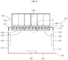
- FIG. 2 shows the electron generator 120 of FIG. 1 .
- the electron generator 120 includes a circuit module 130, a support structure 140, a discharge pin module 150, a discharge plate 160, and electromagnetic field generators 190.
- the circuit module 130 includes a main board 131, and distribution processing boards 135 connected to the main board 131.
- the main board 131 is generally in the shape of a flat plate, and has connectors 132 to which the distribution processing boards 135 are connected.
- the connectors 132 are spaced apart from each other along the horizontal and vertical directions on the main board 131.
- the distribution processing boards 135 are positioned on one surface of the main board 131 (upper surface in the drawing).
- Each of the distribution processing boards 135 has a stand-alone high-voltage high-frequency pulse transformer circuit to apply individual high-voltage high-frequency pulsed power.
- the distribution processing boards 135 are each connected to the connectors 132 of the main board 131 on one surface of the main board 131 (upper surface in the drawing).
- the main board 131 and the distribution processing boards 135 connected to the main board 131 maintain tight coupling by coupling means 138 to form the integrated circuit module 130.
- the circuit module 130 is detachably coupled to the support structure 140.
- the support structure 140 includes a body 141, and a coupling plate 145 detachably coupled to the body 141.
- the body 141 includes a bottom plate 142, a sidewall 143 extending from the bottom plate 142, and a flange 144 extending inward from the top of the sidewall 143.
- the body 141 has an empty space inside, and an inner area of the flange 144 is open.
- the electromagnetic field generators 190 are installed and positioned on the bottom plate 142 and the sidewall 143 in the internal space of the body 141. Electrons moves downward by the electromagnetic field generators 190 in the internal space of the body 141.
- the coupling plate 145 is detachably coupled to the flange 144 with coupling means 147 such as a screw, covering the open top of the body 141.
- the circuit module 130, the discharge pin module 150 and the discharge plate 160 are detachably coupled to the coupling plate 145.
- the circuit module 130 is positioned outside of the support structure 140 with the coupling plate 145 interposed between, and the discharge pin module 150 and the discharge plate 160 are positioned in the internal space of the body 141.
- the coupling plate 145 is made of an electrical insulating material, and has connection protrusions 146 corresponding to the distribution processing boards 135 one-to-one.
- connection protrusions 146 protrude from the coupling plate 145 toward the corresponding distribution processing boards 135, and are made of an electrical conducting material.
- the connection protrusions 146 are exposed at the opposite surface facing the discharge pin module 150. Electricity is applied to the discharge pin module 150 by the corresponding distribution processing boards 135 through the connection protrusions 146.
- the discharge pin module 150 includes a support plate 151, discharge pins 155 coupled to the support plate 151, and elastic connection elements 158.
- the support plate 151 is generally in the shape of a flat plate, and is positioned at a predetermined distance apart from the coupling plate 145 at the opposite side to the main board 131 with the coupling plate 145 interposed between.
- the support plate 151 is made of an electrical insulating material.
- the support plate 151 is where the discharge pins 155 and the elastic connection elements 158 are coupled to each other.
- the discharge pins 155 protrude from the support plate 151 toward the opposite side to the coupling plate 145.
- the discharge pin 155 is made of an electrical conducting material, and this embodiment describes that the discharge pin 155 is formed of a screw fitted into the support plate 151.
- the discharge pin 155 or the screw has a head 156 positioned on the side facing the coupling plate 145, and a longitudinally extending body 157 that protrudes longitudinally to the opposite side.
- Adjacent discharge pins from the discharge pins 155 form a group of discharge pins electrically connected.
- This embodiment describes that a group of discharge pins include four discharge pins 155, but the present disclosure is not limited thereto.
- the four discharge pins 155 forming a group of discharge pins are electrically connected to each other by the elastic connection element 158. High voltage from the corresponding distribution processing board 135 is applied to the group of discharge pins.
- the elastic connection elements 158 are each fixed to the support plate 151 by fixing means or a fixing screw 149 on the surface of the support plate 151 facing the coupling plate 145.
- the elastic connection element 158 is a compression coil spring made of an electrical conducting material.
- One elastic connection element 158 electrically connects four discharge pins 155 that form a group of discharge pin. The ends of the elastic connection elements 158 are contacted with and electrically connected to the corresponding connection protrusions 146 formed on the coupling plate 145.
- the discharge plate 160 is generally in the shape of a flat plate, and is made of an electrical conducting material.
- the discharge plate 160 is positioned at a predetermined distance apart from the discharge pins 155 in the internal space of the body 141 of the support structure 140.
- the discharge plate 160 is detachably coupled to the coupling plate 145 by coupling means 170, together with the discharge pin module 150.
- Corona discharge takes place between the discharge pin 155 and the discharge plate 160, and ionized electrons and radicals emitted from the discharge pin 155 serving as (-) electrode are moved to the discharge plate 160 serving as (+) electrode.
- the discharge plate 160 has through-holes 165 each positioned at a shortest distance corresponding to the discharge pins 155 one-to-one. In the event that impurities, including dust, from the discharge pins 155 are accumulated on the discharge plate 160 at the initial time of discharge, the through-holes 165 maintain a shortest discharge distance to improve the discharge efficiency.
- the electromagnetic field generators 190 are each installed on the bottom plate 142 and the sidewall 143 of the body 141 to move the electrons and radicals emitted from the discharge pins 155 toward the bottom plate 142.
- Each of the electromagnetic field generators 190 includes a core of stainless steel plated with zinc and a coil wound around the core, and may have any configuration to generate an electromagnetic field.
- Electron generation apparatus 110 Case 120: Electron generator 130: Circuit module 131: Main board 135: Distribution processing board 140: Support structure 141: Body 145: Coupling plate 146: Connection protrusion 150: Discharge pin module 151: Support plate 155: Discharge pin 158: Elastic connection element 160: Discharge plate 165: Through-hole 190: Electromagnetic field generator
Landscapes
- Chemical & Material Sciences (AREA)
- Engineering & Computer Science (AREA)
- General Chemical & Material Sciences (AREA)
- Hydrology & Water Resources (AREA)
- Environmental & Geological Engineering (AREA)
- Water Supply & Treatment (AREA)
- Organic Chemistry (AREA)
- Chemical Kinetics & Catalysis (AREA)
- Life Sciences & Earth Sciences (AREA)
- Electrochemistry (AREA)
- Physics & Mathematics (AREA)
- Plasma & Fusion (AREA)
- Analytical Chemistry (AREA)
- Oil, Petroleum & Natural Gas (AREA)
- Disinfection, Sterilisation Or Deodorisation Of Air (AREA)
- Physical Or Chemical Processes And Apparatus (AREA)
- Water Treatment By Electricity Or Magnetism (AREA)
- Plasma Technology (AREA)
Description
- The present disclosure relates to an electron generation apparatus, and more particularly, to an electron generation apparatus for use in wastewater treatment, pollutant treatment and odor elimination.
- Generally, a typical technology or structure known as generating negative ion under atmospheric pressure condition is corona discharge. The corona discharge technology is designed to induce the generation of corona discharge between each electrode by applying high voltage to the electrodes for each of the corresponding polarities.
- The corona discharge generated in this way may be classified into positive corona and negative corona according to the condition of voltage applied to the electrodes for each polarity. Among them, positive corona is more likely to spatially expand than negative corona, but negative corona which generates a greater amount of free electrons and radicals is widely used in the field of industrial equipment.
- Further, technology for generating free electron and negative ion is classified into pulsed power, AC power and DC power forms according to the type of power supply to apply power to each electrode. In this instance, conventional ozone generators or negative oxygen ion generators using pulsed power have a pin-plate structure composed largely of discharge pin and ground. The (+) electrode assumes a plate shape and the (-) electrode assumes a pin shape, and when pulsed power is applied to each electrode, a corona discharge is formed, and in this instance, ozone or negative oxygen ion is generated. However, the conventional power generators have a plurality of discharge pins and a complex structure in which power is applied to each discharge pin, resulting in low operation efficiency in replacing the components.
-
- (Patent Literature 1) Korean Patent No.
10-0529749 - (Patent Literature 2) Korean Patent No.
10-1042141 - (Patent Literature 3)
DE 26 18 745 A1 "Method and apparatus for charging a fiber bundle", (1976.04.28.). This document shows an apparatus comprising a pin module partially surrounded by a support structure. Electricity can be applied to the pin module, which in turn charges fibers located outside of the support structure at a distance to the pin module. - (Patent Literature 4)
US 4 523 082 A1 "Electrode shield device" shows a discharge pin module and a discharge plate in a support structure, preferably an oven. - The present disclosure is directed to providing an electron generation apparatus with a simple structure for applying power and high operation efficiency in maintenance and repair.
- To achieve the object of the present disclosure, according to an aspect of the present disclosure, there is provided an electron generation apparatus including a
discharge pin module 150 provided with asupport plate 151,discharge pins 155 coupled to the support plate, and anelastic connection element 158 electrically connecting a group of discharge pins with each other including at least two adjacent discharge pins from the discharge pins and coupled to the support plate, adischarge plate 160 placed facing the discharge pins, asupport structure 140 provided with acoupling plate 145 positioned at an opposite side to the discharge plate with the support plate interposed between, wherein the discharge pin module and the discharge plate are detachably coupled to the coupling plate, and acircuit module 130 provided with amain board 131 positioned apart from the coupling plate at an opposite side to the discharge pin module with the coupling plate interposed between, anddistribution processing boards 135 connected to the main board such that individual high-voltage high-frequency pulsed power can be applied to the group of discharge pins by a corresponding distribution processing board, wherein the coupling plate is provided withconnection protrusions 146 each electrically connected to the distribution processing boards, and an end of the elastic connection element comes into contact with the connection protrusion. - The discharge plate may have through-holes each corresponding to the discharge pins.
- The elastic connection element may be a compression coil spring.
- The support structure may be further provided with a body which provides an internal space for receiving the discharge pin module and the discharge plate and which has an open top, and the coupling plate may be coupled to the body, covering the open top of the body.
- The electron generation apparatus may further include an electromagnetic field generator installed in the internal space of the body to guide movement of electron and radical emitted from the discharge pin.
- According to the present disclosure, the aforementioned objects of the present disclosure can be all achieved. Specifically, there is provided an electron generation apparatus including a
discharge pin module 150 provided with asupport plate 151,discharge pins 155 coupled to the support plate, and anelastic connection element 158 electrically connecting a group of discharge pins including at least two adjacent discharge pins from the discharge pins and coupled to the support plate, adischarge plate 160 placed facing the discharge pins, asupport structure 140 positioned at an opposite side to the discharge plate with the support plate interposed between and provided with acoupling plate 145 to which the discharge pin module and the discharge plate are detachably coupled, and acircuit module 130 provided with amain board 131 positioned apart from the coupling plate at an opposite side to the discharge pin module with the coupling plate interposed between, anddistribution processing boards 135 connected to the main board to apply individual high-voltage high-frequency pulsed power to the group of discharge pins, wherein the coupling plate is provided withconnection protrusions 146 each electrically connected to the distribution processing boards, and an end of the elastic connection element comes into contact with the connection protrusion, thereby facilitating the assembly and disassembly of the circuit module, the discharge pin module and the discharge plate, and as a consequence, improving the operation efficiency. -
-
FIG. 1 is a side view of an electron generation apparatus according to an embodiment of the present disclosure, in which internal parts are visible. -
FIG. 2 is an enlarged view of an electron generator inFIG. 1 . -
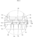
FIG. 3 is an enlarged view of section 'A' inFIG. 2 . -
FIG. 4 is an exploded perspective view of a main structure inFIG. 2 . -
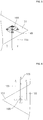
FIGS. 5 and 6 are partial enlarged views of top and bottom of a discharge pin plate show inFIG. 4 . - Hereinafter, the configuration and operation of the embodiments of the present disclosure are described in detail with reference to the accompanying drawings.
-
FIG. 1 is a side view of an electron generation apparatus according to an embodiment of the present disclosure, in which internal parts are visible. Referring toFIG. 1 , theelectron generation apparatus 100 includes anexternal case 110, and anelectron generator 120 received in theexternal case 110. A controller to control theelectron generator 120 and a power supply to apply power supply are positioned above theelectron generator 120 and received in theexternal case 110 together. -
FIG. 2 shows theelectron generator 120 ofFIG. 1 . Referring toFIG. 2 , theelectron generator 120 includes acircuit module 130, asupport structure 140, adischarge pin module 150, adischarge plate 160, andelectromagnetic field generators 190. - Referring to
FIGS. 2 to 4 , thecircuit module 130 includes amain board 131, anddistribution processing boards 135 connected to themain board 131. - The
main board 131 is generally in the shape of a flat plate, and hasconnectors 132 to which thedistribution processing boards 135 are connected. Theconnectors 132 are spaced apart from each other along the horizontal and vertical directions on themain board 131. Thedistribution processing boards 135 are positioned on one surface of the main board 131 (upper surface in the drawing). - Each of the
distribution processing boards 135 has a stand-alone high-voltage high-frequency pulse transformer circuit to apply individual high-voltage high-frequency pulsed power. Thedistribution processing boards 135 are each connected to theconnectors 132 of themain board 131 on one surface of the main board 131 (upper surface in the drawing). - The
main board 131 and thedistribution processing boards 135 connected to themain board 131 maintain tight coupling by coupling means 138 to form the integratedcircuit module 130. Thecircuit module 130 is detachably coupled to thesupport structure 140. - The
support structure 140 includes abody 141, and acoupling plate 145 detachably coupled to thebody 141. Thebody 141 includes abottom plate 142, asidewall 143 extending from thebottom plate 142, and aflange 144 extending inward from the top of thesidewall 143. Thebody 141 has an empty space inside, and an inner area of theflange 144 is open. Theelectromagnetic field generators 190 are installed and positioned on thebottom plate 142 and thesidewall 143 in the internal space of thebody 141. Electrons moves downward by theelectromagnetic field generators 190 in the internal space of thebody 141. Thecoupling plate 145 is detachably coupled to theflange 144 with coupling means 147 such as a screw, covering the open top of thebody 141. Thecircuit module 130, thedischarge pin module 150 and thedischarge plate 160 are detachably coupled to thecoupling plate 145. Thecircuit module 130 is positioned outside of thesupport structure 140 with thecoupling plate 145 interposed between, and thedischarge pin module 150 and thedischarge plate 160 are positioned in the internal space of thebody 141. Thecoupling plate 145 is made of an electrical insulating material, and hasconnection protrusions 146 corresponding to thedistribution processing boards 135 one-to-one. Theconnection protrusions 146 protrude from thecoupling plate 145 toward the correspondingdistribution processing boards 135, and are made of an electrical conducting material. Theconnection protrusions 146 are exposed at the opposite surface facing thedischarge pin module 150. Electricity is applied to thedischarge pin module 150 by the correspondingdistribution processing boards 135 through theconnection protrusions 146. - The
discharge pin module 150 includes asupport plate 151,discharge pins 155 coupled to thesupport plate 151, andelastic connection elements 158. - The
support plate 151 is generally in the shape of a flat plate, and is positioned at a predetermined distance apart from thecoupling plate 145 at the opposite side to themain board 131 with thecoupling plate 145 interposed between. Thesupport plate 151 is made of an electrical insulating material. Thesupport plate 151 is where thedischarge pins 155 and theelastic connection elements 158 are coupled to each other. - The
discharge pins 155 protrude from thesupport plate 151 toward the opposite side to thecoupling plate 145. Thedischarge pin 155 is made of an electrical conducting material, and this embodiment describes that thedischarge pin 155 is formed of a screw fitted into thesupport plate 151. Thedischarge pin 155 or the screw has a head 156 positioned on the side facing thecoupling plate 145, and a longitudinally extending body 157 that protrudes longitudinally to the opposite side. Adjacent discharge pins from the discharge pins 155 form a group of discharge pins electrically connected. This embodiment describes that a group of discharge pins include fourdischarge pins 155, but the present disclosure is not limited thereto. The fourdischarge pins 155 forming a group of discharge pins are electrically connected to each other by theelastic connection element 158. High voltage from the correspondingdistribution processing board 135 is applied to the group of discharge pins. - The
elastic connection elements 158 are each fixed to thesupport plate 151 by fixing means or a fixingscrew 149 on the surface of thesupport plate 151 facing thecoupling plate 145. In this embodiment, theelastic connection element 158 is a compression coil spring made of an electrical conducting material. Oneelastic connection element 158 electrically connects fourdischarge pins 155 that form a group of discharge pin. The ends of theelastic connection elements 158 are contacted with and electrically connected to thecorresponding connection protrusions 146 formed on thecoupling plate 145. - The
discharge plate 160 is generally in the shape of a flat plate, and is made of an electrical conducting material. Thedischarge plate 160 is positioned at a predetermined distance apart from the discharge pins 155 in the internal space of thebody 141 of thesupport structure 140. Thedischarge plate 160 is detachably coupled to thecoupling plate 145 by coupling means 170, together with thedischarge pin module 150. Corona discharge takes place between thedischarge pin 155 and thedischarge plate 160, and ionized electrons and radicals emitted from thedischarge pin 155 serving as (-) electrode are moved to thedischarge plate 160 serving as (+) electrode. Thedischarge plate 160 has through-holes 165 each positioned at a shortest distance corresponding to the discharge pins 155 one-to-one. In the event that impurities, including dust, from the discharge pins 155 are accumulated on thedischarge plate 160 at the initial time of discharge, the through-holes 165 maintain a shortest discharge distance to improve the discharge efficiency. - The
electromagnetic field generators 190 are each installed on thebottom plate 142 and thesidewall 143 of thebody 141 to move the electrons and radicals emitted from the discharge pins 155 toward thebottom plate 142. Each of theelectromagnetic field generators 190 includes a core of stainless steel plated with zinc and a coil wound around the core, and may have any configuration to generate an electromagnetic field. - While the present disclosure has been hereinabove described through the embodiments, the present disclosure is not limited thereto. Modifications or changes may be made thereto without departing from the scope of the present disclosure, and those skilled in the art will understand that these modifications and changes fall within the present disclosure.
[Detailed Description of Main Elements] 100: Electron generation apparatus 110: Case 120: Electron generator 130: Circuit module 131: Main board 135: Distribution processing board 140: Support structure 141: Body 145: Coupling plate 146: Connection protrusion 150: Discharge pin module 151: Support plate 155: Discharge pin 158: Elastic connection element 160: Discharge plate 165: Through-hole 190: Electromagnetic field generator
Claims (5)
- An electron generation apparatus, comprising:a discharge pin module (150) provided with a support plate (151), discharge pins (155) coupled to the support plate (151), and an elastic connection element (158) electrically connecting a group of discharge pins (155) with each other including at least two adjacent discharge pins (155) from the discharge pins (155) and coupled to the support plate (151);a discharge plate (160) placed facing the discharge pins (155);a support structure (140) provided with a coupling plate (145) positioned at an opposite side to the discharge plate (160) with the support plate (151) interposed between, wherein the discharge pin module (150) and the discharge plate (160) are detachably coupled to the coupling plate (145); anda circuit module (130) provided with a main board (131) positioned apart from the coupling plate (145) at an opposite side to the discharge pin module (150) with the coupling plate (145) interposed between, and distribution processing boards (135) connected to the main board (131) such that individual high-voltage high-frequency pulsed power can be applied to the group of discharge pins (155) by a corresponding distribution processing board (135),wherein the coupling plate (145) is provided with connection protrusions (146) each electrically connected to the distribution processing boards (135), andan end of the elastic connection element (158) comes into contact with the connection protrusion (146).
- The electron generation apparatus according to claim 1, wherein the discharge plate (160) has through-holes each corresponding to the discharge pins (155).
- The electron generation apparatus according to claim 1, wherein the elastic connection element (158) is a compression coil spring.
- The electron generation apparatus according to claim 1, wherein the support structure (140) is further provided with a body which provides an internal space for receiving the discharge pin module (150) and the discharge plate (160), and which has an open top, and
the coupling plate (145) is coupled to the body, covering the open top of the body. - The electron generation apparatus according to claim 4, further comprising:
an electromagnetic field generator installed in the internal space of the body to guide movement of electron and radical emitted from the discharge pin.
Applications Claiming Priority (1)
| Application Number | Priority Date | Filing Date | Title |
|---|---|---|---|
| KR1020170061411A KR101787322B1 (en) | 2017-05-18 | 2017-05-18 | Electron generation apparatus |
Publications (2)
| Publication Number | Publication Date |
|---|---|
| EP3404782A1 EP3404782A1 (en) | 2018-11-21 |
| EP3404782B1 true EP3404782B1 (en) | 2020-06-17 |
Family
ID=60298130
Family Applications (1)
| Application Number | Title | Priority Date | Filing Date |
|---|---|---|---|
| EP18160887.8A Active EP3404782B1 (en) | 2017-05-18 | 2018-03-09 | Electron generation apparatus |
Country Status (4)
| Country | Link |
|---|---|
| US (1) | US10032593B1 (en) |
| EP (1) | EP3404782B1 (en) |
| JP (1) | JP6404433B1 (en) |
| KR (1) | KR101787322B1 (en) |
Families Citing this family (9)
| Publication number | Priority date | Publication date | Assignee | Title |
|---|---|---|---|---|
| KR102060500B1 (en) * | 2017-11-23 | 2020-02-20 | 주식회사 그룬 | Wastewater risk material reduction equipment for removing ecotoxicity and system thereof |
| KR101942009B1 (en) * | 2018-10-11 | 2019-04-11 | 농업회사법인 어의당 주식회사 | Composition for preventing, ameliorating or treating dermatitis comprising complex of natural oil and natural extract treated with anion generated by plasma as effective component |
| JP2020062190A (en) | 2018-10-17 | 2020-04-23 | セイコーエプソン株式会社 | Watchband, exterior component for watch and watch |
| KR102229265B1 (en) * | 2019-11-18 | 2021-03-18 | (주)그룬 | Electron generation apparatus capable of multi-stage boosting for variable capacity |
| EP3823112A1 (en) * | 2019-11-18 | 2021-05-19 | Groon Co., Ltd. | Electron generation apparatus capable of multi-stage boosting for variable capacity |
| KR102325807B1 (en) * | 2019-11-18 | 2021-11-12 | (주)그룬 | Electron generation apparatus |
| US12576372B2 (en) | 2022-06-30 | 2026-03-17 | Soave Enterprises Llc | Method and apparatus to mix gas with a fluid |
| KR102833090B1 (en) * | 2023-05-10 | 2025-07-14 | 전북대학교산학협력단 | Apparatus for discharging corona |
| US20250235845A1 (en) | 2023-12-22 | 2025-07-24 | Soave Enterprises Llc | Method And Apparatus To Activate Molecules In A Fluid |
Family Cites Families (12)
| Publication number | Priority date | Publication date | Assignee | Title |
|---|---|---|---|---|
| US3967118A (en) * | 1975-04-29 | 1976-06-29 | Monsanto Company | Method and apparatus for charging a bundle of filaments |
| US4523082A (en) * | 1983-05-05 | 1985-06-11 | Sturdevant Eugene J | Electrode shield device |
| JPH0287399U (en) * | 1988-12-26 | 1990-07-11 | ||
| KR19990007560A (en) | 1998-10-08 | 1999-01-25 | 윤명렬 | Wastewater Treatment System Using High Voltage Discharge |
| US6338347B1 (en) * | 2000-04-04 | 2002-01-15 | Yun-Yin Chung | Blood circulation stimulator |
| KR100529749B1 (en) | 2002-12-09 | 2005-11-22 | (주) 이오 | High Voltage And High Frequency Pulse Process Electron Generation Device For A Pollutant Treatment |
| KR100537223B1 (en) | 2002-12-16 | 2005-12-20 | (주) 이오 | Waste Treatment Device And Method Thereof Using By Electromagnetic Wave And Active Electron |
| JP2007157541A (en) * | 2005-12-06 | 2007-06-21 | Shishido Seidenki Kk | Ion generating device |
| KR101042141B1 (en) | 2008-08-21 | 2011-06-16 | 이인호 | Electromagnetic generator for high frequency pulse odor removal |
| KR101295349B1 (en) * | 2012-11-23 | 2013-08-12 | 주식회사 그룬 | A wastewaster treatment apparatus using electron discharge of high-voltage |
| KR101372432B1 (en) * | 2013-06-24 | 2014-03-10 | (주)성창기공수처리공사 | A ion sterilizer made of silver and bornze for water treatment |
| KR101303832B1 (en) * | 2013-08-02 | 2013-09-04 | 문영근 | Discharging system of high-voltage for removing scum |
-
2017
- 2017-05-18 KR KR1020170061411A patent/KR101787322B1/en active Active
- 2017-10-18 US US15/786,728 patent/US10032593B1/en active Active
- 2017-10-20 JP JP2017203132A patent/JP6404433B1/en active Active
-
2018
- 2018-03-09 EP EP18160887.8A patent/EP3404782B1/en active Active
Non-Patent Citations (1)
| Title |
|---|
| None * |
Also Published As
| Publication number | Publication date |
|---|---|
| KR101787322B1 (en) | 2017-10-17 |
| US10032593B1 (en) | 2018-07-24 |
| EP3404782A1 (en) | 2018-11-21 |
| JP6404433B1 (en) | 2018-10-10 |
| JP2018195555A (en) | 2018-12-06 |
Similar Documents
| Publication | Publication Date | Title |
|---|---|---|
| EP3404782A1 (en) | Electron generation apparatus | |
| KR101656781B1 (en) | X-ray Ionizer | |
| US8049170B2 (en) | Induction electrode, ion generation element, ion generation apparatus, and electric equipment | |
| RU2011108990A (en) | INSTALLATION GENERATING IONS AND ELECTRICAL EQUIPMENT USING IT | |
| JP6527977B2 (en) | Ion generator | |
| CN204205286U (en) | Ion generating device | |
| CN102254764A (en) | Bearing device of component | |
| KR102024678B1 (en) | Plasma generator for agriculture and livestock industry | |
| JP2016520959A (en) | X-ray generator, X-ray generator and high voltage generator constituting the same | |
| US7612981B2 (en) | Ion generator and neutralizer | |
| JP2008262746A (en) | Ion balance adjusting electrode and static eliminator having the same | |
| US10797472B1 (en) | Electron generation apparatus capable of multi-stage boosting for variable capacity | |
| TWI589190B (en) | X-ray ionizer | |
| KR101117248B1 (en) | ceramic electrode structure for generating ion and ion generation apparatus | |
| JP2009099472A (en) | Blast type ion generating device | |
| KR20240002535A (en) | High-concentration wastewater treatment device that treats pollutants with strong oxidizing power using plasma | |
| KR102325807B1 (en) | Electron generation apparatus | |
| JP2011054308A (en) | Static eliminator and static elimination method | |
| CN104486899B (en) | A kind of plasma generator with mounting structure | |
| KR102229265B1 (en) | Electron generation apparatus capable of multi-stage boosting for variable capacity | |
| WO2014034840A1 (en) | Ion generator and ion generation device equipped with same | |
| JP6725938B2 (en) | Ion generator | |
| KR101253345B1 (en) | Device for generating ion and method thereof | |
| MX2020009323A (en) | Methods, apparatus and systems for dry-type transformers. | |
| KR101237253B1 (en) | Static eliminator |
Legal Events
| Date | Code | Title | Description |
|---|---|---|---|
| PUAI | Public reference made under article 153(3) epc to a published international application that has entered the european phase |
Free format text: ORIGINAL CODE: 0009012 |
|
| STAA | Information on the status of an ep patent application or granted ep patent |
Free format text: STATUS: REQUEST FOR EXAMINATION WAS MADE |
|
| 17P | Request for examination filed |
Effective date: 20180319 |
|
| AK | Designated contracting states |
Kind code of ref document: A1 Designated state(s): AL AT BE BG CH CY CZ DE DK EE ES FI FR GB GR HR HU IE IS IT LI LT LU LV MC MK MT NL NO PL PT RO RS SE SI SK SM TR |
|
| AX | Request for extension of the european patent |
Extension state: BA ME |
|
| RBV | Designated contracting states (corrected) |
Designated state(s): AL AT BE BG CH CY CZ DE DK EE ES FI FR GB GR HR HU IE IS IT LI LT LU LV MC MK MT NL NO PL PT RO RS SE SI SK SM TR |
|
| GRAP | Despatch of communication of intention to grant a patent |
Free format text: ORIGINAL CODE: EPIDOSNIGR1 |
|
| RIC1 | Information provided on ipc code assigned before grant |
Ipc: H01T 19/04 20060101AFI20191211BHEP Ipc: H01T 23/00 20060101ALI20191211BHEP Ipc: C02F 1/46 20060101ALI20191211BHEP |
|
| STAA | Information on the status of an ep patent application or granted ep patent |
Free format text: STATUS: GRANT OF PATENT IS INTENDED |
|
| INTG | Intention to grant announced |
Effective date: 20200116 |
|
| GRAS | Grant fee paid |
Free format text: ORIGINAL CODE: EPIDOSNIGR3 |
|
| GRAA | (expected) grant |
Free format text: ORIGINAL CODE: 0009210 |
|
| STAA | Information on the status of an ep patent application or granted ep patent |
Free format text: STATUS: THE PATENT HAS BEEN GRANTED |
|
| AK | Designated contracting states |
Kind code of ref document: B1 Designated state(s): AL AT BE BG CH CY CZ DE DK EE ES FI FR GB GR HR HU IE IS IT LI LT LU LV MC MK MT NL NO PL PT RO RS SE SI SK SM TR |
|
| REG | Reference to a national code |
Ref country code: GB Ref legal event code: FG4D |
|
| REG | Reference to a national code |
Ref country code: CH Ref legal event code: EP |
|
| REG | Reference to a national code |
Ref country code: IE Ref legal event code: FG4D |
|
| REG | Reference to a national code |
Ref country code: DE Ref legal event code: R096 Ref document number: 602018005262 Country of ref document: DE |
|
| REG | Reference to a national code |
Ref country code: AT Ref legal event code: REF Ref document number: 1282496 Country of ref document: AT Kind code of ref document: T Effective date: 20200715 |
|
| REG | Reference to a national code |
Ref country code: NL Ref legal event code: FP |
|
| PG25 | Lapsed in a contracting state [announced via postgrant information from national office to epo] |
Ref country code: FI Free format text: LAPSE BECAUSE OF FAILURE TO SUBMIT A TRANSLATION OF THE DESCRIPTION OR TO PAY THE FEE WITHIN THE PRESCRIBED TIME-LIMIT Effective date: 20200617 Ref country code: LT Free format text: LAPSE BECAUSE OF FAILURE TO SUBMIT A TRANSLATION OF THE DESCRIPTION OR TO PAY THE FEE WITHIN THE PRESCRIBED TIME-LIMIT Effective date: 20200617 Ref country code: NO Free format text: LAPSE BECAUSE OF FAILURE TO SUBMIT A TRANSLATION OF THE DESCRIPTION OR TO PAY THE FEE WITHIN THE PRESCRIBED TIME-LIMIT Effective date: 20200917 Ref country code: SE Free format text: LAPSE BECAUSE OF FAILURE TO SUBMIT A TRANSLATION OF THE DESCRIPTION OR TO PAY THE FEE WITHIN THE PRESCRIBED TIME-LIMIT Effective date: 20200617 Ref country code: GR Free format text: LAPSE BECAUSE OF FAILURE TO SUBMIT A TRANSLATION OF THE DESCRIPTION OR TO PAY THE FEE WITHIN THE PRESCRIBED TIME-LIMIT Effective date: 20200918 |
|
| REG | Reference to a national code |
Ref country code: LT Ref legal event code: MG4D |
|
| PG25 | Lapsed in a contracting state [announced via postgrant information from national office to epo] |
Ref country code: BG Free format text: LAPSE BECAUSE OF FAILURE TO SUBMIT A TRANSLATION OF THE DESCRIPTION OR TO PAY THE FEE WITHIN THE PRESCRIBED TIME-LIMIT Effective date: 20200917 Ref country code: RS Free format text: LAPSE BECAUSE OF FAILURE TO SUBMIT A TRANSLATION OF THE DESCRIPTION OR TO PAY THE FEE WITHIN THE PRESCRIBED TIME-LIMIT Effective date: 20200617 Ref country code: HR Free format text: LAPSE BECAUSE OF FAILURE TO SUBMIT A TRANSLATION OF THE DESCRIPTION OR TO PAY THE FEE WITHIN THE PRESCRIBED TIME-LIMIT Effective date: 20200617 Ref country code: LV Free format text: LAPSE BECAUSE OF FAILURE TO SUBMIT A TRANSLATION OF THE DESCRIPTION OR TO PAY THE FEE WITHIN THE PRESCRIBED TIME-LIMIT Effective date: 20200617 |
|
| REG | Reference to a national code |
Ref country code: AT Ref legal event code: MK05 Ref document number: 1282496 Country of ref document: AT Kind code of ref document: T Effective date: 20200617 |
|
| PG25 | Lapsed in a contracting state [announced via postgrant information from national office to epo] |
Ref country code: AL Free format text: LAPSE BECAUSE OF FAILURE TO SUBMIT A TRANSLATION OF THE DESCRIPTION OR TO PAY THE FEE WITHIN THE PRESCRIBED TIME-LIMIT Effective date: 20200617 |
|
| PG25 | Lapsed in a contracting state [announced via postgrant information from national office to epo] |
Ref country code: EE Free format text: LAPSE BECAUSE OF FAILURE TO SUBMIT A TRANSLATION OF THE DESCRIPTION OR TO PAY THE FEE WITHIN THE PRESCRIBED TIME-LIMIT Effective date: 20200617 Ref country code: AT Free format text: LAPSE BECAUSE OF FAILURE TO SUBMIT A TRANSLATION OF THE DESCRIPTION OR TO PAY THE FEE WITHIN THE PRESCRIBED TIME-LIMIT Effective date: 20200617 Ref country code: IT Free format text: LAPSE BECAUSE OF FAILURE TO SUBMIT A TRANSLATION OF THE DESCRIPTION OR TO PAY THE FEE WITHIN THE PRESCRIBED TIME-LIMIT Effective date: 20200617 Ref country code: SM Free format text: LAPSE BECAUSE OF FAILURE TO SUBMIT A TRANSLATION OF THE DESCRIPTION OR TO PAY THE FEE WITHIN THE PRESCRIBED TIME-LIMIT Effective date: 20200617 Ref country code: RO Free format text: LAPSE BECAUSE OF FAILURE TO SUBMIT A TRANSLATION OF THE DESCRIPTION OR TO PAY THE FEE WITHIN THE PRESCRIBED TIME-LIMIT Effective date: 20200617 Ref country code: CZ Free format text: LAPSE BECAUSE OF FAILURE TO SUBMIT A TRANSLATION OF THE DESCRIPTION OR TO PAY THE FEE WITHIN THE PRESCRIBED TIME-LIMIT Effective date: 20200617 Ref country code: ES Free format text: LAPSE BECAUSE OF FAILURE TO SUBMIT A TRANSLATION OF THE DESCRIPTION OR TO PAY THE FEE WITHIN THE PRESCRIBED TIME-LIMIT Effective date: 20200617 Ref country code: PT Free format text: LAPSE BECAUSE OF FAILURE TO SUBMIT A TRANSLATION OF THE DESCRIPTION OR TO PAY THE FEE WITHIN THE PRESCRIBED TIME-LIMIT Effective date: 20201019 |
|
| PG25 | Lapsed in a contracting state [announced via postgrant information from national office to epo] |
Ref country code: PL Free format text: LAPSE BECAUSE OF FAILURE TO SUBMIT A TRANSLATION OF THE DESCRIPTION OR TO PAY THE FEE WITHIN THE PRESCRIBED TIME-LIMIT Effective date: 20200617 Ref country code: SK Free format text: LAPSE BECAUSE OF FAILURE TO SUBMIT A TRANSLATION OF THE DESCRIPTION OR TO PAY THE FEE WITHIN THE PRESCRIBED TIME-LIMIT Effective date: 20200617 Ref country code: IS Free format text: LAPSE BECAUSE OF FAILURE TO SUBMIT A TRANSLATION OF THE DESCRIPTION OR TO PAY THE FEE WITHIN THE PRESCRIBED TIME-LIMIT Effective date: 20201017 |
|
| REG | Reference to a national code |
Ref country code: DE Ref legal event code: R097 Ref document number: 602018005262 Country of ref document: DE |
|
| PLBE | No opposition filed within time limit |
Free format text: ORIGINAL CODE: 0009261 |
|
| STAA | Information on the status of an ep patent application or granted ep patent |
Free format text: STATUS: NO OPPOSITION FILED WITHIN TIME LIMIT |
|
| PG25 | Lapsed in a contracting state [announced via postgrant information from national office to epo] |
Ref country code: DK Free format text: LAPSE BECAUSE OF FAILURE TO SUBMIT A TRANSLATION OF THE DESCRIPTION OR TO PAY THE FEE WITHIN THE PRESCRIBED TIME-LIMIT Effective date: 20200617 |
|
| 26N | No opposition filed |
Effective date: 20210318 |
|
| PG25 | Lapsed in a contracting state [announced via postgrant information from national office to epo] |
Ref country code: SI Free format text: LAPSE BECAUSE OF FAILURE TO SUBMIT A TRANSLATION OF THE DESCRIPTION OR TO PAY THE FEE WITHIN THE PRESCRIBED TIME-LIMIT Effective date: 20200617 |
|
| PG25 | Lapsed in a contracting state [announced via postgrant information from national office to epo] |
Ref country code: MC Free format text: LAPSE BECAUSE OF FAILURE TO SUBMIT A TRANSLATION OF THE DESCRIPTION OR TO PAY THE FEE WITHIN THE PRESCRIBED TIME-LIMIT Effective date: 20200617 |
|
| REG | Reference to a national code |
Ref country code: CH Ref legal event code: PL |
|
| REG | Reference to a national code |
Ref country code: BE Ref legal event code: MM Effective date: 20210331 |
|
| PG25 | Lapsed in a contracting state [announced via postgrant information from national office to epo] |
Ref country code: LI Free format text: LAPSE BECAUSE OF NON-PAYMENT OF DUE FEES Effective date: 20210331 Ref country code: LU Free format text: LAPSE BECAUSE OF NON-PAYMENT OF DUE FEES Effective date: 20210309 Ref country code: CH Free format text: LAPSE BECAUSE OF NON-PAYMENT OF DUE FEES Effective date: 20210331 Ref country code: IE Free format text: LAPSE BECAUSE OF NON-PAYMENT OF DUE FEES Effective date: 20210309 |
|
| PG25 | Lapsed in a contracting state [announced via postgrant information from national office to epo] |
Ref country code: BE Free format text: LAPSE BECAUSE OF NON-PAYMENT OF DUE FEES Effective date: 20210331 |
|
| PG25 | Lapsed in a contracting state [announced via postgrant information from national office to epo] |
Ref country code: CY Free format text: LAPSE BECAUSE OF FAILURE TO SUBMIT A TRANSLATION OF THE DESCRIPTION OR TO PAY THE FEE WITHIN THE PRESCRIBED TIME-LIMIT Effective date: 20200617 |
|
| PG25 | Lapsed in a contracting state [announced via postgrant information from national office to epo] |
Ref country code: HU Free format text: LAPSE BECAUSE OF FAILURE TO SUBMIT A TRANSLATION OF THE DESCRIPTION OR TO PAY THE FEE WITHIN THE PRESCRIBED TIME-LIMIT; INVALID AB INITIO Effective date: 20180309 |
|
| PG25 | Lapsed in a contracting state [announced via postgrant information from national office to epo] |
Ref country code: MK Free format text: LAPSE BECAUSE OF FAILURE TO SUBMIT A TRANSLATION OF THE DESCRIPTION OR TO PAY THE FEE WITHIN THE PRESCRIBED TIME-LIMIT Effective date: 20200617 |
|
| PG25 | Lapsed in a contracting state [announced via postgrant information from national office to epo] |
Ref country code: MT Free format text: LAPSE BECAUSE OF FAILURE TO SUBMIT A TRANSLATION OF THE DESCRIPTION OR TO PAY THE FEE WITHIN THE PRESCRIBED TIME-LIMIT Effective date: 20200617 |
|
| PGFP | Annual fee paid to national office [announced via postgrant information from national office to epo] |
Ref country code: NL Payment date: 20250327 Year of fee payment: 8 |
|
| PGFP | Annual fee paid to national office [announced via postgrant information from national office to epo] |
Ref country code: FR Payment date: 20250327 Year of fee payment: 8 |
|
| PGFP | Annual fee paid to national office [announced via postgrant information from national office to epo] |
Ref country code: DE Payment date: 20250417 Year of fee payment: 8 |
|
| PGFP | Annual fee paid to national office [announced via postgrant information from national office to epo] |
Ref country code: GB Payment date: 20250423 Year of fee payment: 8 |
|
| PG25 | Lapsed in a contracting state [announced via postgrant information from national office to epo] |
Ref country code: TR Free format text: LAPSE BECAUSE OF FAILURE TO SUBMIT A TRANSLATION OF THE DESCRIPTION OR TO PAY THE FEE WITHIN THE PRESCRIBED TIME-LIMIT Effective date: 20200617 |