EP3404754A1 - Electrode for secondary battery, secondary battery, battery pack, and vehicle - Google Patents
Electrode for secondary battery, secondary battery, battery pack, and vehicle Download PDFInfo
- Publication number
- EP3404754A1 EP3404754A1 EP18158085.3A EP18158085A EP3404754A1 EP 3404754 A1 EP3404754 A1 EP 3404754A1 EP 18158085 A EP18158085 A EP 18158085A EP 3404754 A1 EP3404754 A1 EP 3404754A1
- Authority
- EP
- European Patent Office
- Prior art keywords
- positive electrode
- active material
- electrode active
- battery
- material particles
- Prior art date
- Legal status (The legal status is an assumption and is not a legal conclusion. Google has not performed a legal analysis and makes no representation as to the accuracy of the status listed.)
- Withdrawn
Links
- 239000007774 positive electrode material Substances 0.000 claims abstract description 186
- 239000002245 particle Substances 0.000 claims abstract description 85
- OKTJSMMVPCPJKN-UHFFFAOYSA-N Carbon Chemical compound [C] OKTJSMMVPCPJKN-UHFFFAOYSA-N 0.000 claims abstract description 34
- 229910052799 carbon Inorganic materials 0.000 claims abstract description 24
- 239000006258 conductive agent Substances 0.000 claims description 23
- 239000011230 binding agent Substances 0.000 claims description 22
- 230000001681 protective effect Effects 0.000 claims description 15
- 229910052782 aluminium Inorganic materials 0.000 claims description 12
- 229910052748 manganese Inorganic materials 0.000 claims description 12
- 230000001172 regenerating effect Effects 0.000 claims description 7
- 229910052759 nickel Inorganic materials 0.000 claims description 4
- 229910015530 LixMO2 Inorganic materials 0.000 claims description 3
- 239000011255 nonaqueous electrolyte Substances 0.000 description 41
- 229910013840 LiNi0.34Co0.33Mn0.33O2 Inorganic materials 0.000 description 31
- 229910002986 Li4Ti5O12 Inorganic materials 0.000 description 30
- 230000000052 comparative effect Effects 0.000 description 28
- 239000007773 negative electrode material Substances 0.000 description 23
- 238000004519 manufacturing process Methods 0.000 description 13
- 229910000838 Al alloy Inorganic materials 0.000 description 12
- 239000002033 PVDF binder Substances 0.000 description 12
- 239000011888 foil Substances 0.000 description 12
- 229910052751 metal Inorganic materials 0.000 description 12
- 239000002184 metal Substances 0.000 description 12
- -1 polytetrafluoroethylene Polymers 0.000 description 12
- 229920002981 polyvinylidene fluoride Polymers 0.000 description 12
- 238000001878 scanning electron micrograph Methods 0.000 description 12
- XEEYBQQBJWHFJM-UHFFFAOYSA-N iron Substances [Fe] XEEYBQQBJWHFJM-UHFFFAOYSA-N 0.000 description 11
- HBBGRARXTFLTSG-UHFFFAOYSA-N Lithium ion Chemical compound [Li+] HBBGRARXTFLTSG-UHFFFAOYSA-N 0.000 description 10
- 229910052802 copper Inorganic materials 0.000 description 10
- 239000010949 copper Substances 0.000 description 10
- 229910052742 iron Inorganic materials 0.000 description 10
- 229910001416 lithium ion Inorganic materials 0.000 description 10
- 239000011777 magnesium Substances 0.000 description 10
- 229910052749 magnesium Inorganic materials 0.000 description 10
- 239000000463 material Substances 0.000 description 10
- 229910052710 silicon Inorganic materials 0.000 description 10
- 239000002002 slurry Substances 0.000 description 10
- 239000010936 titanium Substances 0.000 description 10
- 229910052725 zinc Inorganic materials 0.000 description 10
- 239000011701 zinc Substances 0.000 description 10
- XAGFODPZIPBFFR-UHFFFAOYSA-N aluminium Chemical compound [Al] XAGFODPZIPBFFR-UHFFFAOYSA-N 0.000 description 9
- 238000004891 communication Methods 0.000 description 9
- 239000011572 manganese Substances 0.000 description 9
- 229910052719 titanium Inorganic materials 0.000 description 9
- OIFBSDVPJOWBCH-UHFFFAOYSA-N Diethyl carbonate Chemical compound CCOC(=O)OCC OIFBSDVPJOWBCH-UHFFFAOYSA-N 0.000 description 8
- SECXISVLQFMRJM-UHFFFAOYSA-N N-Methylpyrrolidone Chemical compound CN1CCCC1=O SECXISVLQFMRJM-UHFFFAOYSA-N 0.000 description 8
- 239000003792 electrolyte Substances 0.000 description 8
- 239000005001 laminate film Substances 0.000 description 8
- RUOJZAUFBMNUDX-UHFFFAOYSA-N propylene carbonate Chemical compound CC1COC(=O)O1 RUOJZAUFBMNUDX-UHFFFAOYSA-N 0.000 description 8
- 239000003575 carbonaceous material Substances 0.000 description 7
- 238000007599 discharging Methods 0.000 description 7
- 238000012806 monitoring device Methods 0.000 description 7
- WEVYAHXRMPXWCK-UHFFFAOYSA-N Acetonitrile Chemical compound CC#N WEVYAHXRMPXWCK-UHFFFAOYSA-N 0.000 description 6
- KMTRUDSVKNLOMY-UHFFFAOYSA-N Ethylene carbonate Chemical compound O=C1OCCO1 KMTRUDSVKNLOMY-UHFFFAOYSA-N 0.000 description 6
- 239000011248 coating agent Substances 0.000 description 6
- 238000000576 coating method Methods 0.000 description 6
- 239000002131 composite material Substances 0.000 description 6
- 238000002156 mixing Methods 0.000 description 6
- 238000012360 testing method Methods 0.000 description 6
- 239000004698 Polyethylene Substances 0.000 description 5
- 238000010586 diagram Methods 0.000 description 5
- 229910052744 lithium Inorganic materials 0.000 description 5
- 239000012046 mixed solvent Substances 0.000 description 5
- 239000003960 organic solvent Substances 0.000 description 5
- 229920000573 polyethylene Polymers 0.000 description 5
- WHXSMMKQMYFTQS-UHFFFAOYSA-N Lithium Chemical compound [Li] WHXSMMKQMYFTQS-UHFFFAOYSA-N 0.000 description 4
- 239000004743 Polypropylene Substances 0.000 description 4
- WYURNTSHIVDZCO-UHFFFAOYSA-N Tetrahydrofuran Chemical compound C1CCOC1 WYURNTSHIVDZCO-UHFFFAOYSA-N 0.000 description 4
- 239000006230 acetylene black Substances 0.000 description 4
- 239000011149 active material Substances 0.000 description 4
- 239000007864 aqueous solution Substances 0.000 description 4
- 238000001514 detection method Methods 0.000 description 4
- 239000008151 electrolyte solution Substances 0.000 description 4
- 229910002804 graphite Inorganic materials 0.000 description 4
- 239000010439 graphite Substances 0.000 description 4
- 239000007788 liquid Substances 0.000 description 4
- RSNHXDVSISOZOB-UHFFFAOYSA-N lithium nickel Chemical compound [Li].[Ni] RSNHXDVSISOZOB-UHFFFAOYSA-N 0.000 description 4
- 238000000034 method Methods 0.000 description 4
- PXHVJJICTQNCMI-UHFFFAOYSA-N nickel Substances [Ni] PXHVJJICTQNCMI-UHFFFAOYSA-N 0.000 description 4
- 229920001155 polypropylene Polymers 0.000 description 4
- 229920001343 polytetrafluoroethylene Polymers 0.000 description 4
- 239000004810 polytetrafluoroethylene Substances 0.000 description 4
- 229920005989 resin Polymers 0.000 description 4
- 239000011347 resin Substances 0.000 description 4
- 238000004458 analytical method Methods 0.000 description 3
- IEJIGPNLZYLLBP-UHFFFAOYSA-N dimethyl carbonate Chemical compound COC(=O)OC IEJIGPNLZYLLBP-UHFFFAOYSA-N 0.000 description 3
- 229920001971 elastomer Polymers 0.000 description 3
- JBTWLSYIZRCDFO-UHFFFAOYSA-N ethyl methyl carbonate Chemical compound CCOC(=O)OC JBTWLSYIZRCDFO-UHFFFAOYSA-N 0.000 description 3
- 229910001496 lithium tetrafluoroborate Inorganic materials 0.000 description 3
- CXHHBNMLPJOKQD-UHFFFAOYSA-M methyl carbonate Chemical compound COC([O-])=O CXHHBNMLPJOKQD-UHFFFAOYSA-M 0.000 description 3
- 239000002861 polymer material Substances 0.000 description 3
- 230000000630 rising effect Effects 0.000 description 3
- 239000005060 rubber Substances 0.000 description 3
- 238000005507 spraying Methods 0.000 description 3
- WNXJIVFYUVYPPR-UHFFFAOYSA-N 1,3-dioxolane Chemical compound C1COCO1 WNXJIVFYUVYPPR-UHFFFAOYSA-N 0.000 description 2
- GEWWCWZGHNIUBW-UHFFFAOYSA-N 1-(4-nitrophenyl)propan-2-one Chemical compound CC(=O)CC1=CC=C([N+]([O-])=O)C=C1 GEWWCWZGHNIUBW-UHFFFAOYSA-N 0.000 description 2
- JWUJQDFVADABEY-UHFFFAOYSA-N 2-methyltetrahydrofuran Chemical compound CC1CCCO1 JWUJQDFVADABEY-UHFFFAOYSA-N 0.000 description 2
- 239000004925 Acrylic resin Substances 0.000 description 2
- 229920000178 Acrylic resin Polymers 0.000 description 2
- XKRFYHLGVUSROY-UHFFFAOYSA-N Argon Chemical compound [Ar] XKRFYHLGVUSROY-UHFFFAOYSA-N 0.000 description 2
- 229920002134 Carboxymethyl cellulose Polymers 0.000 description 2
- QGLBZNZGBLRJGS-UHFFFAOYSA-N Dihydro-3-methyl-2(3H)-furanone Chemical compound CC1CCOC1=O QGLBZNZGBLRJGS-UHFFFAOYSA-N 0.000 description 2
- XTHFKEDIFFGKHM-UHFFFAOYSA-N Dimethoxyethane Chemical compound COCCOC XTHFKEDIFFGKHM-UHFFFAOYSA-N 0.000 description 2
- YCKRFDGAMUMZLT-UHFFFAOYSA-N Fluorine atom Chemical compound [F] YCKRFDGAMUMZLT-UHFFFAOYSA-N 0.000 description 2
- 229910009337 Li1.33Mn0.67O2 Inorganic materials 0.000 description 2
- 229910032387 LiCoO2 Inorganic materials 0.000 description 2
- 229910003260 Nb2TiO7 Inorganic materials 0.000 description 2
- 239000004677 Nylon Substances 0.000 description 2
- 229920003171 Poly (ethylene oxide) Polymers 0.000 description 2
- 229910010251 TiO2(B) Inorganic materials 0.000 description 2
- 229920005822 acrylic binder Polymers 0.000 description 2
- 239000002390 adhesive tape Substances 0.000 description 2
- 239000006229 carbon black Substances 0.000 description 2
- 239000002134 carbon nanofiber Substances 0.000 description 2
- 239000002041 carbon nanotube Substances 0.000 description 2
- 229910021393 carbon nanotube Inorganic materials 0.000 description 2
- 239000001768 carboxy methyl cellulose Substances 0.000 description 2
- 235000010948 carboxy methyl cellulose Nutrition 0.000 description 2
- 239000008112 carboxymethyl-cellulose Substances 0.000 description 2
- 239000001913 cellulose Substances 0.000 description 2
- 229920002678 cellulose Polymers 0.000 description 2
- 230000008859 change Effects 0.000 description 2
- 230000006866 deterioration Effects 0.000 description 2
- 238000002149 energy-dispersive X-ray emission spectroscopy Methods 0.000 description 2
- 239000011737 fluorine Substances 0.000 description 2
- 229910052731 fluorine Inorganic materials 0.000 description 2
- 239000011810 insulating material Substances 0.000 description 2
- 229910003002 lithium salt Inorganic materials 0.000 description 2
- 159000000002 lithium salts Chemical class 0.000 description 2
- SWAIALBIBWIKKQ-UHFFFAOYSA-N lithium titanium Chemical compound [Li].[Ti] SWAIALBIBWIKKQ-UHFFFAOYSA-N 0.000 description 2
- 238000012423 maintenance Methods 0.000 description 2
- 238000013507 mapping Methods 0.000 description 2
- 230000007246 mechanism Effects 0.000 description 2
- VNWKTOKETHGBQD-UHFFFAOYSA-N methane Chemical compound C VNWKTOKETHGBQD-UHFFFAOYSA-N 0.000 description 2
- 239000004745 nonwoven fabric Substances 0.000 description 2
- 229920001778 nylon Polymers 0.000 description 2
- 239000008188 pellet Substances 0.000 description 2
- 229920002239 polyacrylonitrile Polymers 0.000 description 2
- 229920000139 polyethylene terephthalate Polymers 0.000 description 2
- 239000005020 polyethylene terephthalate Substances 0.000 description 2
- 239000000843 powder Substances 0.000 description 2
- 238000003825 pressing Methods 0.000 description 2
- 239000011164 primary particle Substances 0.000 description 2
- 238000007789 sealing Methods 0.000 description 2
- 239000002904 solvent Substances 0.000 description 2
- HXJUTPCZVOIRIF-UHFFFAOYSA-N sulfolane Chemical compound O=S1(=O)CCCC1 HXJUTPCZVOIRIF-UHFFFAOYSA-N 0.000 description 2
- YLQBMQCUIZJEEH-UHFFFAOYSA-N tetrahydrofuran Natural products C=1C=COC=1 YLQBMQCUIZJEEH-UHFFFAOYSA-N 0.000 description 2
- 238000004804 winding Methods 0.000 description 2
- VAYTZRYEBVHVLE-UHFFFAOYSA-N 1,3-dioxol-2-one Chemical compound O=C1OC=CO1 VAYTZRYEBVHVLE-UHFFFAOYSA-N 0.000 description 1
- VYZAMTAEIAYCRO-UHFFFAOYSA-N Chromium Chemical compound [Cr] VYZAMTAEIAYCRO-UHFFFAOYSA-N 0.000 description 1
- RYGMFSIKBFXOCR-UHFFFAOYSA-N Copper Chemical compound [Cu] RYGMFSIKBFXOCR-UHFFFAOYSA-N 0.000 description 1
- 229910010401 Li2Na2Ti6O14 Inorganic materials 0.000 description 1
- 229910010479 Li4Ti5O2 Inorganic materials 0.000 description 1
- 229910015694 LiNi0.85Co0.1Al0.05O2 Inorganic materials 0.000 description 1
- 229910015872 LiNi0.8Co0.1Mn0.1O2 Inorganic materials 0.000 description 1
- FYYHWMGAXLPEAU-UHFFFAOYSA-N Magnesium Chemical compound [Mg] FYYHWMGAXLPEAU-UHFFFAOYSA-N 0.000 description 1
- XUIMIQQOPSSXEZ-UHFFFAOYSA-N Silicon Chemical compound [Si] XUIMIQQOPSSXEZ-UHFFFAOYSA-N 0.000 description 1
- RTAQQCXQSZGOHL-UHFFFAOYSA-N Titanium Chemical compound [Ti] RTAQQCXQSZGOHL-UHFFFAOYSA-N 0.000 description 1
- HCHKCACWOHOZIP-UHFFFAOYSA-N Zinc Chemical compound [Zn] HCHKCACWOHOZIP-UHFFFAOYSA-N 0.000 description 1
- FKQOMXQAEKRXDM-UHFFFAOYSA-N [Li].[As] Chemical compound [Li].[As] FKQOMXQAEKRXDM-UHFFFAOYSA-N 0.000 description 1
- 229910052786 argon Inorganic materials 0.000 description 1
- 230000008901 benefit Effects 0.000 description 1
- 150000005678 chain carbonates Chemical class 0.000 description 1
- 238000006243 chemical reaction Methods 0.000 description 1
- 229910052804 chromium Inorganic materials 0.000 description 1
- 239000011651 chromium Substances 0.000 description 1
- 150000005676 cyclic carbonates Chemical class 0.000 description 1
- 150000004292 cyclic ethers Chemical class 0.000 description 1
- 238000000354 decomposition reaction Methods 0.000 description 1
- 238000009826 distribution Methods 0.000 description 1
- 150000002170 ethers Chemical class 0.000 description 1
- 239000008187 granular material Substances 0.000 description 1
- 238000005469 granulation Methods 0.000 description 1
- 230000003179 granulation Effects 0.000 description 1
- 230000017525 heat dissipation Effects 0.000 description 1
- 238000010438 heat treatment Methods 0.000 description 1
- 230000006872 improvement Effects 0.000 description 1
- 238000010030 laminating Methods 0.000 description 1
- 239000011244 liquid electrolyte Substances 0.000 description 1
- MHCFAGZWMAWTNR-UHFFFAOYSA-M lithium perchlorate Chemical compound [Li+].[O-]Cl(=O)(=O)=O MHCFAGZWMAWTNR-UHFFFAOYSA-M 0.000 description 1
- MCVFFRWZNYZUIJ-UHFFFAOYSA-M lithium;trifluoromethanesulfonate Chemical compound [Li+].[O-]S(=O)(=O)C(F)(F)F MCVFFRWZNYZUIJ-UHFFFAOYSA-M 0.000 description 1
- 230000007774 longterm Effects 0.000 description 1
- 229910001092 metal group alloy Inorganic materials 0.000 description 1
- 229910044991 metal oxide Inorganic materials 0.000 description 1
- 150000004706 metal oxides Chemical class 0.000 description 1
- 229910052976 metal sulfide Inorganic materials 0.000 description 1
- 238000012544 monitoring process Methods 0.000 description 1
- 238000000465 moulding Methods 0.000 description 1
- 150000004767 nitrides Chemical class 0.000 description 1
- 238000001556 precipitation Methods 0.000 description 1
- 238000002360 preparation method Methods 0.000 description 1
- 239000002994 raw material Substances 0.000 description 1
- 230000004044 response Effects 0.000 description 1
- 150000003839 salts Chemical class 0.000 description 1
- 238000004626 scanning electron microscopy Methods 0.000 description 1
- 239000010703 silicon Substances 0.000 description 1
- 229910052596 spinel Inorganic materials 0.000 description 1
- 239000011029 spinel Substances 0.000 description 1
- 238000000992 sputter etching Methods 0.000 description 1
- 238000006467 substitution reaction Methods 0.000 description 1
- 229920003002 synthetic resin Polymers 0.000 description 1
- 239000000057 synthetic resin Substances 0.000 description 1
- 229910052723 transition metal Inorganic materials 0.000 description 1
- 150000003624 transition metals Chemical class 0.000 description 1
- 239000013585 weight reducing agent Substances 0.000 description 1
Images



Classifications
-
- H—ELECTRICITY
- H01—ELECTRIC ELEMENTS
- H01M—PROCESSES OR MEANS, e.g. BATTERIES, FOR THE DIRECT CONVERSION OF CHEMICAL ENERGY INTO ELECTRICAL ENERGY
- H01M4/00—Electrodes
- H01M4/02—Electrodes composed of, or comprising, active material
- H01M4/36—Selection of substances as active materials, active masses, active liquids
- H01M4/362—Composites
- H01M4/366—Composites as layered products
-
- H—ELECTRICITY
- H01—ELECTRIC ELEMENTS
- H01M—PROCESSES OR MEANS, e.g. BATTERIES, FOR THE DIRECT CONVERSION OF CHEMICAL ENERGY INTO ELECTRICAL ENERGY
- H01M10/00—Secondary cells; Manufacture thereof
- H01M10/05—Accumulators with non-aqueous electrolyte
- H01M10/052—Li-accumulators
- H01M10/0525—Rocking-chair batteries, i.e. batteries with lithium insertion or intercalation in both electrodes; Lithium-ion batteries
-
- H—ELECTRICITY
- H01—ELECTRIC ELEMENTS
- H01M—PROCESSES OR MEANS, e.g. BATTERIES, FOR THE DIRECT CONVERSION OF CHEMICAL ENERGY INTO ELECTRICAL ENERGY
- H01M10/00—Secondary cells; Manufacture thereof
- H01M10/05—Accumulators with non-aqueous electrolyte
- H01M10/058—Construction or manufacture
-
- H—ELECTRICITY
- H01—ELECTRIC ELEMENTS
- H01M—PROCESSES OR MEANS, e.g. BATTERIES, FOR THE DIRECT CONVERSION OF CHEMICAL ENERGY INTO ELECTRICAL ENERGY
- H01M10/00—Secondary cells; Manufacture thereof
- H01M10/42—Methods or arrangements for servicing or maintenance of secondary cells or secondary half-cells
- H01M10/425—Structural combination with electronic components, e.g. electronic circuits integrated to the outside of the casing
-
- H—ELECTRICITY
- H01—ELECTRIC ELEMENTS
- H01M—PROCESSES OR MEANS, e.g. BATTERIES, FOR THE DIRECT CONVERSION OF CHEMICAL ENERGY INTO ELECTRICAL ENERGY
- H01M10/00—Secondary cells; Manufacture thereof
- H01M10/42—Methods or arrangements for servicing or maintenance of secondary cells or secondary half-cells
- H01M10/44—Methods for charging or discharging
-
- H—ELECTRICITY
- H01—ELECTRIC ELEMENTS
- H01M—PROCESSES OR MEANS, e.g. BATTERIES, FOR THE DIRECT CONVERSION OF CHEMICAL ENERGY INTO ELECTRICAL ENERGY
- H01M4/00—Electrodes
- H01M4/02—Electrodes composed of, or comprising, active material
- H01M4/13—Electrodes for accumulators with non-aqueous electrolyte, e.g. for lithium-accumulators; Processes of manufacture thereof
- H01M4/131—Electrodes based on mixed oxides or hydroxides, or on mixtures of oxides or hydroxides, e.g. LiCoOx
-
- H—ELECTRICITY
- H01—ELECTRIC ELEMENTS
- H01M—PROCESSES OR MEANS, e.g. BATTERIES, FOR THE DIRECT CONVERSION OF CHEMICAL ENERGY INTO ELECTRICAL ENERGY
- H01M4/00—Electrodes
- H01M4/02—Electrodes composed of, or comprising, active material
- H01M4/13—Electrodes for accumulators with non-aqueous electrolyte, e.g. for lithium-accumulators; Processes of manufacture thereof
- H01M4/139—Processes of manufacture
- H01M4/1391—Processes of manufacture of electrodes based on mixed oxides or hydroxides, or on mixtures of oxides or hydroxides, e.g. LiCoOx
-
- H—ELECTRICITY
- H01—ELECTRIC ELEMENTS
- H01M—PROCESSES OR MEANS, e.g. BATTERIES, FOR THE DIRECT CONVERSION OF CHEMICAL ENERGY INTO ELECTRICAL ENERGY
- H01M4/00—Electrodes
- H01M4/02—Electrodes composed of, or comprising, active material
- H01M4/36—Selection of substances as active materials, active masses, active liquids
- H01M4/48—Selection of substances as active materials, active masses, active liquids of inorganic oxides or hydroxides
- H01M4/50—Selection of substances as active materials, active masses, active liquids of inorganic oxides or hydroxides of manganese
- H01M4/505—Selection of substances as active materials, active masses, active liquids of inorganic oxides or hydroxides of manganese of mixed oxides or hydroxides containing manganese for inserting or intercalating light metals, e.g. LiMn2O4 or LiMn2OxFy
-
- H—ELECTRICITY
- H01—ELECTRIC ELEMENTS
- H01M—PROCESSES OR MEANS, e.g. BATTERIES, FOR THE DIRECT CONVERSION OF CHEMICAL ENERGY INTO ELECTRICAL ENERGY
- H01M4/00—Electrodes
- H01M4/02—Electrodes composed of, or comprising, active material
- H01M4/36—Selection of substances as active materials, active masses, active liquids
- H01M4/48—Selection of substances as active materials, active masses, active liquids of inorganic oxides or hydroxides
- H01M4/52—Selection of substances as active materials, active masses, active liquids of inorganic oxides or hydroxides of nickel, cobalt or iron
- H01M4/525—Selection of substances as active materials, active masses, active liquids of inorganic oxides or hydroxides of nickel, cobalt or iron of mixed oxides or hydroxides containing iron, cobalt or nickel for inserting or intercalating light metals, e.g. LiNiO2, LiCoO2 or LiCoOxFy
-
- H—ELECTRICITY
- H01—ELECTRIC ELEMENTS
- H01M—PROCESSES OR MEANS, e.g. BATTERIES, FOR THE DIRECT CONVERSION OF CHEMICAL ENERGY INTO ELECTRICAL ENERGY
- H01M4/00—Electrodes
- H01M4/02—Electrodes composed of, or comprising, active material
- H01M4/62—Selection of inactive substances as ingredients for active masses, e.g. binders, fillers
- H01M4/624—Electric conductive fillers
- H01M4/625—Carbon or graphite
-
- H—ELECTRICITY
- H01—ELECTRIC ELEMENTS
- H01M—PROCESSES OR MEANS, e.g. BATTERIES, FOR THE DIRECT CONVERSION OF CHEMICAL ENERGY INTO ELECTRICAL ENERGY
- H01M4/00—Electrodes
- H01M4/02—Electrodes composed of, or comprising, active material
- H01M2004/026—Electrodes composed of, or comprising, active material characterised by the polarity
- H01M2004/027—Negative electrodes
-
- H—ELECTRICITY
- H01—ELECTRIC ELEMENTS
- H01M—PROCESSES OR MEANS, e.g. BATTERIES, FOR THE DIRECT CONVERSION OF CHEMICAL ENERGY INTO ELECTRICAL ENERGY
- H01M4/00—Electrodes
- H01M4/02—Electrodes composed of, or comprising, active material
- H01M2004/026—Electrodes composed of, or comprising, active material characterised by the polarity
- H01M2004/028—Positive electrodes
-
- H—ELECTRICITY
- H01—ELECTRIC ELEMENTS
- H01M—PROCESSES OR MEANS, e.g. BATTERIES, FOR THE DIRECT CONVERSION OF CHEMICAL ENERGY INTO ELECTRICAL ENERGY
- H01M2220/00—Batteries for particular applications
- H01M2220/20—Batteries in motive systems, e.g. vehicle, ship, plane
-
- Y—GENERAL TAGGING OF NEW TECHNOLOGICAL DEVELOPMENTS; GENERAL TAGGING OF CROSS-SECTIONAL TECHNOLOGIES SPANNING OVER SEVERAL SECTIONS OF THE IPC; TECHNICAL SUBJECTS COVERED BY FORMER USPC CROSS-REFERENCE ART COLLECTIONS [XRACs] AND DIGESTS
- Y02—TECHNOLOGIES OR APPLICATIONS FOR MITIGATION OR ADAPTATION AGAINST CLIMATE CHANGE
- Y02E—REDUCTION OF GREENHOUSE GAS [GHG] EMISSIONS, RELATED TO ENERGY GENERATION, TRANSMISSION OR DISTRIBUTION
- Y02E60/00—Enabling technologies; Technologies with a potential or indirect contribution to GHG emissions mitigation
- Y02E60/10—Energy storage using batteries
-
- Y—GENERAL TAGGING OF NEW TECHNOLOGICAL DEVELOPMENTS; GENERAL TAGGING OF CROSS-SECTIONAL TECHNOLOGIES SPANNING OVER SEVERAL SECTIONS OF THE IPC; TECHNICAL SUBJECTS COVERED BY FORMER USPC CROSS-REFERENCE ART COLLECTIONS [XRACs] AND DIGESTS
- Y02—TECHNOLOGIES OR APPLICATIONS FOR MITIGATION OR ADAPTATION AGAINST CLIMATE CHANGE
- Y02P—CLIMATE CHANGE MITIGATION TECHNOLOGIES IN THE PRODUCTION OR PROCESSING OF GOODS
- Y02P70/00—Climate change mitigation technologies in the production process for final industrial or consumer products
- Y02P70/50—Manufacturing or production processes characterised by the final manufactured product
Definitions
- Embodiments relate to an electrode for a secondary battery, a secondary battery, a battery pack, and a vehicle.
- Lithium titanium composite oxide has a small volume change that is accompanied with charge and discharge, and therefore has excellent cycle characteristics. Furthermore, in principle, the lithium inserting and extracting reaction of lithium titanium composite oxide hardly allows precipitation of the lithium metal, and thus there is only a small performance deterioration even when charge and discharge is repeated at high current.
- a lithium nickel composite oxide which has a high-capacity is used.
- particles of the lithium nickel composite oxide are cracked due to the volume change when the charge/discharge cycle is carried out, in particular, under the high temperature environment.
- Fig. 1A is a schematic cross-sectional view of a nonaqueous electrolyte battery
- Fig. 1B is an enlarged view of part A illustrated in Fig. 1A .
- a flat wound electrode group 1 is received in a baglike outer casing member 2, which is made of a laminate film, having an aluminum foil interposed between two sheets of resin layers as the outer casing member 2.
- the flat wound electrode group 1 is formed by spirally winding a laminate in which a negative electrode 3, a separator 4, a positive electrode 5, and a separator 4 are laminated in order from an outside and press molding the laminate.
- the outermost negative electrode 3 is configured of a negative electrode active material layer 3b that is formed on one surface of an inner surface side of a negative electrode current collector 3a.
- a negative electrode 3 other than the outermost negative electrode 3 is configured of the negative electrode active material layers 3b that are formed on both surfaces of the negative electrode current collector 3a.
- the positive electrode 5 is configured of positive electrode active material layers 5b that are formed on both surfaces of a positive electrode current collector 5a.
- a negative electrode terminal 6 is connected to the negative electrode current collector 3a of the outermost negative electrode 3.
- a positive electrode terminal 7 is connected to the positive electrode current collector 5a of the positive electrode 5.
- the negative electrode terminal 6 and the positive electrode terminal 7 extend from an opening portion of the baglike outer casing member 2 to the outside.
- a liquid nonaqueous electrolyte is injected from the opening portion of the baglike outer casing member 2.
- An opening of baglike outer casing member 2 is heat sealed in a state where the negative electrode terminal 6 and the positive electrode terminal 7 extend to the outside, such that the wound electrode group 1 and the liquid nonaqueous electrolyte are completely sealed.
- the negative electrode terminal 6 is made of a material having electric stability and conductivity in a range in which a potential for lithium ion metal is 1V or more and 3V or less.
- the negative electrode terminal 6 is made of an aluminum alloy including one element of, for example, Mg, Ti, Zn, Mn, Fe, Cu, and Si.
- the negative electrode terminal 6 may be made of an aluminum alloy including plural elements of, for example, Mg, Ti, Zn, Mn, Fe, Cu, and Si.
- the negative electrode terminal 6 is made of the same material as the negative electrode current collector 3a.
- the positive electrode terminal 7 is made of a material having electric stability and conductivity in a range in which a potential for lithium ion metal is 3V or more and 4.5V or less.
- the positive electrode terminal 7 is made of an aluminum alloy including at least one element of Mg, Ti, Zn, Mn, Fe, Cu, and Si.
- the positive electrode terminal 7 may be made of an aluminum alloy including plural elements of Mg, Ti, Zn, Mn, Fe, Cu, and Si. In order to reduce a contact resistance with the positive electrode current collector 5a, it is preferable that the positive electrode terminal 7 is made of the same material as the positive electrode current collector 5a.
- the negative electrode 3, the positive electrode 5, the nonaqueous electrolyte, the separator 4, the outer casing member 2, the positive electrode terminal 7, and the negative electrode terminal 6 that are used in the nonaqueous electrolyte battery of the present embodiment will be described in detail.
- the negative electrode 3 includes the negative electrode current collector 3a and the negative electrode active material layer 3b.
- the negative electrode current collector 3a is preferably made of an aluminum foil or an aluminum alloy foil including one element of Mg, Ti, Zn, Mn, Fe, Cu, and Si, which is electrochemically stable in a range in which a potential is more than 1.0V.
- the negative electrode active material layer 3b includes a negative electrode active material, a conductive agent, and a binder.
- the negative electrode active material layer 3b is formed on one surface or both surfaces of the negative electrode current collector 3a.
- the negative electrode active material is in the range of 70 mass% or more and 96 mass% or less
- the negative electrode conductive agent is in the range of 2 mass% or more and 28 mass% or less
- the binder is in the range of 2 mass% or more and 28 mass% or less.
- the mixing ratio of the conductive agent is less than 2 mass%, there is a risk that the current collecting performance of the negative electrode active material layer 3b deteriorates and the large current characteristic of the nonaqueous electrolyte battery deteriorates. If the mixing ratio of the binder is less than 2 mass%, there is a risk that the binding property between the negative electrode active material layer 3b and the negative electrode current collector 3a deteriorates and the cycle characteristics deteriorate. From the viewpoint of the high capacity of the nonaqueous electrolyte battery, it is preferable that the mixing ratio of each of the conductive agent and the binder is 28 mass% or less.
- the negative electrode active material layer 3b a carbonaceous material, a metal oxide, a metal sulfide, a metal nitride, a metal alloy, and the like, which insert and extract lithium ions are exemplified.
- the conductive agent is, for example, a carbonaceous material such as acetylene black, carbon black, graphite, carbon nanofiber, and carbon nanotube.
- the conductive agent may use the carbonaceous material alone, or may use a plurality of carbonaceous materials.
- the binder binds the active material, the conductive agent, and the current collector.
- the binder is, for example, polytetrafluoroethylene (PTFE), polyvinylidene fluoride (PVdF), fluorine-based rubber, acrylic resin, and carboxymethyl cellulose.
- the negative electrode 3 is prepared, for example, by the following method. Slurry is prepared by suspending the negative electrode active material, the conductive agent, and the binder in a solvent. The slurry is applied on one surface or both surfaces of the negative electrode current collector 3a and dried to form the negative electrode active material layer 3b. Thereafter, a press is performed. Alternatively, it is also possible that the negative electrode active material, the conductive agent and the binder are formed in a pellet shape and used as the negative electrode active material layer 3b.
- electrolytic solution for example, a general nonaqueous electrolytic solution including LiPF 6 or LiBF 4 as Li salt and a mixed solvent of propylene carbonate (PC), ethylene carbonate (EC), diethyl carbonate (DEC), dimethyl carbonate (DMC) or the like as an organic solvent is shown.
- PC propylene carbonate
- EC ethylene carbonate
- DEC diethyl carbonate
- DMC dimethyl carbonate
- the positive electrode 5 includes the positive electrode current collector 5a and the positive electrode active material layer 5b.
- the positive electrode active material layer 5b includes the positive electrode active material, the conductive agent, and the binder.
- the positive electrode active material layer 5b is formed on one surface or both surfaces of the positive electrode current collector 5a.
- the positive electrode active material includes Li x MO 2 (0 ⁇ x ⁇ 1.33).
- M is at least one element selected from the group consisting of Ni, Co, Mn, and Al.
- Fig. 2A illustrates a scanning electron microscopy (SEM) image of a cross section of the positive electrode active material granulated body 35 included in the positive electrode active material layer 5b
- Fig. 2B is a view representing the SEM image in black and white (binarized SEM image).
- SEM scanning electron microscopy
- the positive electrode active material granulated body 35 includes voids.
- the positive electrode active material granulated body 35 is made of a plurality of first positive electrode active material particles 30 and a plurality of second positive electrode active material particles 31. It should be noted that the first positive electrode active material particle 30 and the second positive electrode active material particle 31 may be collectively referred to as the positive electrode active material.
- the positive electrode active material granulated body 35 is made of the plurality of first positive electrode active material particles 30 and the second positive electrode active material particles 31 existing on an outer circumference of an aggregated body of the plurality of first positive electrode active material particles 30.
- the portions of the voids of the positive electrode active material granulated body 35 are shown by a black part of the SEM image illustrated in Fig. 2A .
- the positive electrode active material granulated body 35 has substantially a spherical shape.
- a surface of the positive electrode active material granulated body 35 is coated with a carbon layer.
- a part of the surface of the second positive electrode active material particle 31 is coated with the carbon layer.
- the surface of the first positive electrode active material particle 30 does not have the carbon layer.
- the structure described above can be prepared by coating the carbon layer on the surface of the positive electrode active material granulated body.
- the second positive electrode active material particle 31 is disposed on at least a part of the surface of the first positive electrode active material particle 30.
- the second positive electrode active material particle 31 on at least a part of the surface of the first positive electrode active material particle 30.
- the amount of carbon on the surface of the first positive electrode active material particle 30 is smaller than that of the second positive electrode active material particles 31.
- the occupancy rate of the first positive electrode active material particle 30 and the second positive electrode active material particle 31 is preferably 70% or more and 98% or less. More preferably, the occupancy rate of the first positive electrode active material particle 30 and the second positive electrode active material particle 31 is 80% or more and 95% or less. If the occupancy rate of the first positive electrode active material particle 30 and the second positive electrode active material particle 31 is smaller than 70%, the cycle life of the battery pack using the positive electrode 5 will be reduced. If the occupancy rate of the first positive electrode active material particle 30 and the second positive electrode active material particle 31 is larger than 98%, the output density of the battery pack using the positive electrode 5 will be reduced.
- the occupancy rate of the first positive electrode active material particle 30 and the second positive electrode active material particle 31 is in the range described above, it is possible to form the electron conduction path within the positive electrode active material layer 5b while suppressing the lowering in the lithium ion conduction.
- the ratio of the number of second positive electrode active material particles 31 to the total number of first positive electrode active material particles 30 and the second positive electrode active material particle 31 ranges preferably from 0.2 to 0.8, and more preferably from 0.4 to 0.6.
- the number of second positive electrode active material particles 31 is smaller than the above range, the electron conduction path between the carbon layers coated on the second positive electrode active material particles 31 is not sufficiently ensured. For this reason, if the volume expansion/shrinkage of the positive electrode active material layer 5b accompanied by the charge/discharge cycle occurs, there is a risk that the isolated positive electrode active material particles, which do not contribute to the charging/discharging may be generated.
- the number of second positive electrode active material particles 31 is larger than the above-mentioned range, a coverage factor of the carbon layer on the surface of the positive electrode active material granulated body 35 becomes high, such that there is a risk that the lithium ion conduction may be hindered and the output characteristics of the secondary battery may deteriorate.
- the mixing is made so that the amount of the positive electrode active material (or total amount of positive electrode active material and lithium inserting material) in the positive electrode active material layer 5b is 80 mass% or more and 96 mass% or less. It is preferable that the conductive agent is mixed at 3 mass% or more and 19 mass% or less. It is preferable that the binder is mixed at 1 mass% or more and 17 mass% or less.
- the amount of conductive agent is preferably set to be 3 mass% or more. If the amount of the conductive agent is set to be 19 mass% or less, it is possible to reduce the decomposition of the nonaqueous electrolyte on the surface of the conductive agent under the high temperature.
- the amount of the binder By setting the amount of the binder to be 1 mass% or more, it is possible to sufficiently increase the binding property between the positive electrode active material layer 5b and the positive electrode current collector 5a. It is possible to reduce the mixed amount of the binder that is an insulating material in the positive electrode 5 by setting the amount of the binder to be 17 mass% or less. By reducing the mixed amount of the binder that is the insulating material in the positive electrode 5, it is possible to reduce the internal resistance of the positive electrode 5.
- the conductive agent is, for example, a carbonaceous material such as acetylene black, carbon black, graphite, carbon nanofiber, and carbon nanotube.
- the conductive agent may use the carbonaceous material alone, or may use a plurality of carbonaceous materials.
- the binder binds the active material, the conductive agent, and the current collector.
- the binder is, for example, polytetrafluoroethylene (PTFE), polyvinylidene fluoride (PVdF), fluorine-based rubber, acrylic resin, and carboxymethyl cellulose.
- the positive electrode current collector 5a is preferably an aluminum foil or an aluminum alloy foil including one element of Mg, Ti, Zn, Mn, Fe, Cu, and Si.
- the positive electrode current collector 5a may be an aluminum foil or an aluminum alloy foil including plural elements of Mg, Ti, Zn, Mn, Fe, Cu, and Si. Considering the expansion and shrinkage of the positive electrode active material accompanied by the charging/discharging of the nonaqueous electrolyte battery, it is more preferable to use the positive electrode current collector 5a of the electrolytic foil of which the surface is roughly processed.
- the positive electrode 5 is prepared, for example, by the following method.
- the positive electrode active material granulated body 35 is prepared using a tumbling fluidized bed granulation-coating machine.
- the granulation machine granulates the positive electrode active material granulated body using Li x MO 2 (0 ⁇ x ⁇ 1.33, and M is at least one element selected from the group consisting of Ni, Co, Mn, and Al) particles which are the positive electrode active materials. By doing so, the positive electrode active material granulated body 35 is prepared.
- the carbon layer is formed on the surface of the positive electrode active material granulated body 35.
- the positive electrode active material granulated body 35 is baked.
- the slurry is prepared by suspending the positive electrode active material granulated body 35 having a carbon layer formed on the surface thereof in a solvent.
- the slurry is applied on one surface or both surfaces of the current collector and dried.
- the positive electrode 5 is prepared by pressing the dried slurry.
- the positive electrode active material granulated body 35 included in the positive electrode 5 is divided into the first positive electrode active material particle 30 and the second positive electrode active material particle 31.
- the positive electrode active material, the conductive agent, and the binder can be formed into the pellet shape and used as the positive electrode active material layer 5b.
- the occupancy rate of the first positive electrode active material particle 30 and the second positive electrode active material particle 31 can be controlled by the following method. That is, it is preferable to set particle strength of the positive electrode active material granulated body 35 as a raw material to be 100 MPa or less, and more preferably 50 MPa or less. By increasing the temperature at the time of baking the positive electrode active material granulated body 35 and increasing a primary particle diameter, the particle strength of the positive electrode active material granulated body 35 can be kept low.
- the particle strength of the positive electrode active material granulated body 35 can be kept low. In this way, by suppressing the particle strength of the positive electrode active material granulated body 35 to be 100 MPa or less, the positive electrode active material granulated body 35 can be easily crushed when the positive electrode 5 is produced by the press. And thus, in the positive electrode active material granulated body 35 as the positive electrode 5, the occupancy rate of the first positive electrode active material particle 30 and the second positive electrode active material particle 31 can be controlled.
- the occupancy rate of the first positive electrode active material particle 30 and the second positive electrode active material particle 31 can be calculated by the following method.
- the secondary battery is disassembled to take out the positive electrode 5, and the positive electrode 5 is sufficiently washed with ethyl methyl carbonate (MEC), and then dried in vacuum.
- the cross section of the positive electrode active material layer 5b of the positive electrode 5 is cut out by argon ion milling.
- the cross section of the positive electrode active material layer 5b is observed by the SEM and the SEM image of the cross section of the positive electrode active material granulated body 35 included in the positive electrode active material layer 5b is photographed.
- the SEM image of the cross section of the positive electrode active material granulated body 35 of Fig. 2A is photographed at a magnification of 5000 times.
- EDS energy dispersive X-ray spectrometry
- the positive electrode active material granulated body 35 in the positive electrode active material layer 5b is coated with carbon.
- a substantially spherical portion of which the outer circumference is coated with carbon is defined as the positive electrode active material granulated body 35.
- the photographed SEM image of the cross section of the positive electrode active material granulated body 35 is converted into monochrome 256 gradations and is binarized by putting a threshold value.
- the positive electrode active material is represented in white and a gap between positive electrode active material and positive electrode active material and carbon are represented in black.
- an area of a white pixel representing the positive electrode active material is set to be the occupancy rate of the positive electrode active material, i.e., the occupancy rate of the first positive electrode active material particle 30 and the second positive electrode active material particle 31.
- the liquid nonaqueous electrolyte or the gel-like nonaqueous electrolyte is used as the electrolyte.
- the liquid nonaqueous electrolyte is prepared by dissolving the electrolyte with an organic solvent.
- a concentration of the nonaqueous electrolyte is preferably 0.5 mol/l or more and 2.5 mol/l or less.
- the gel-like nonaqueous electrolyte is prepared by compositing the liquid electrolyte with a polymer material.
- Examples of the electrolyte may include lithium salts such as lithium perchlorate (LiClO 4 ), lithium hexafluorophosphate (LiPF 6 ), lithium tetrafluoroborate (LiBF 4 ), lithium arsenic hexafluoride (LiAsF 6 ), lithium trifluoromethane sulfonate (LiCF 3 SO 3 ), and bistrifluoromethylsulfonylimitrithium [LiN (CF 3 SO 2 ) 2 ].
- the electrolyte is used alone or in combination of two or more kinds. It is preferable that the electrolyte contains lithium hexafluorophosphate (LiPF 6 ).
- Examples of the organic solvent may include cyclic carbonates such as propylene carbonate (PC), ethylene carbonate (EC), and vinylene carbonate; chain carbonates such as diethyl carbonate (DEC), dimethyl carbonate (DMC), and methylethyl carbonate (MEC); cyclic ethers such as tetrahydrofuran (THF), 2 methyltetrahydrofuran (2MeTHF), and dioxolane (DOX); chain ethers such as dimethoxyethane (DME) and diethoethane (DEE); and ⁇ -butyrolactone (GBL), ⁇ -methyl- ⁇ -butyrolactone (MBL), acetonitrile (AN), and sulfolane (SL).
- the organic solvents is used alone or in combination of two or more kinds.
- Examples of a more preferable organic solvent may include a mixed solvent obtained by mixing two or more of propylene carbonate (PC), ethylene carbonate (EC), diethyl carbonate (DEC), dimethyl carbonate (DMC), and methylethyl carbonate (MEC), and a mixed solvent including ⁇ -butyrolactone (GBL).
- PC propylene carbonate
- EC ethylene carbonate
- DEC diethyl carbonate
- DMC dimethyl carbonate
- MEC methylethyl carbonate
- GBL ⁇ -butyrolactone
- polymer material examples include polyvinylidene fluoride (PVdF), polyacrylonitrile (PAN), and polyethylene oxide (PEO).
- PVdF polyvinylidene fluoride
- PAN polyacrylonitrile
- PEO polyethylene oxide
- nonaqueous electrolyte instead of the nonaqueous electrolyte, it is also possible to use an aqueous solution including an electrolyte containing the lithium salt.
- a porous film made of a material such as polyethylene, polypropylene, cellulose, and polyvinylidene fluoride (PVdF), a synthetic resin nonwoven fabric, and the like are used as the separator 4.
- the porous film made of polyethylene or polypropylene is preferable from the viewpoint of the improvement in safety of the nonaqueous electrolyte battery because it can be melted at a predetermined temperature and can cut off a current.
- the outer casing member 2 a baglike container formed of a laminate film or a metal container is used.
- the outer casing member 2 is a flat shape, a squared shape, a cylindrical shape, a coin shape, a button shape, a sheet shape, a laminate shape, and the like. Furthermore, it can be small batteries loaded on portable electronic devices and the like, and large batteries loaded on two-wheel or four-wheel automobiles and the like.
- the laminate film a multilayered film having a metal layer interposed between the resin films is used.
- the metal layer an aluminum foil or an aluminum alloy foil is preferable for weight reduction.
- the resin film may use polymer materials such as polypropylene (PP), polyethylene (PE), nylon, and polyethylene terephthalate (PET).
- PP polypropylene
- PE polyethylene
- PET polyethylene terephthalate
- the laminate film is molded in the shape of the outer casing member by performing sealing by heat seal.
- a thickness of the laminate film is preferably 0.2 mm or less.
- the metal container is made of aluminum or an aluminum alloy. It is preferable that the aluminum alloy includes elements such as magnesium, zinc, and silicon. In contrast, the content of transition metal such as iron, copper, nickel, and chromium is preferably 100 ppm or less. By doing so, it is possible to dramatically improve long-term reliability and heat dissipation performance of the metal container under the high temperature environment.
- a thickness of the metal container is preferably 0.5 mm or less.
- the thickness of the metal container is preferably 0.2 mm or less.
- the positive electrode terminal 7 is electrically stable in the range in which a potential for the lithium ion metal is 3.0V or more and 4.5V or less.
- the positive electrode terminal 7 is made of a material having conductivity.
- the positive electrode terminal 7 is made of an aluminum alloy including one kind or plural kinds of elements such as Mg, Ti, Zn, Mn, Fe, Cu, and Si. In order to reduce the contact resistance with the positive electrode current collector 5a, it is preferable that the positive electrode terminal 7 is made of the same material as the positive electrode current collector 5a.
- the negative electrode terminal 6 is electrically stable in the range in which a potential for the lithium ion metal is 1.0V or more and 3.0V or less.
- the negative electrode terminal 6 is made of a material having conductivity.
- the negative electrode terminal 6 is made of an aluminum alloy including one kind or plural kinds of elements such as Mg, Ti, Zn, Mn, Fe, Cu, and Si. In order to reduce the contact resistance with the negative electrode current collector 3a, the negative electrode terminal 6 is made of the same material as the negative electrode current collector 3a.
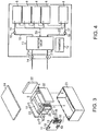
- Fig. 3 is an exploded perspective view of the battery pack.
- the unit battery 8 is configured of the nonaqueous electrolyte battery.
- the plurality of unit batteries 8 are laminated so that the negative electrode terminal 6 and the positive electrode terminal 7 extending to the outside are aligned in the same direction.
- the plurality of unit batteries 8 are fastened to each other with an adhesive tape 9 to configure an assembled battery 10.
- the battery pack has one or a plurality of unit batteries 8 described above.
- each of the unit batteries 8 is electrically connected in series, in parallel, or in a serial-parallel combination.
- the battery pack may further include a protective circuit.
- the protective circuit controls the charging/discharging of the nonaqueous electrolyte battery 8.
- a circuit included in a device that uses the battery pack as a power supply e.g., an electronic device, an automobile and the like
- the battery pack may further include an external terminal for energization.
- the external terminal for energization is provided to output a current from the unit battery 8 to the outside and input a current to the unit battery 8.
- the current is supplied to the outside through an external terminal for energization.
- a charging current (including regenerative energy of power of the automobile) is supplied to the battery pack through the external terminal for energization.
- Fig. 4 illustrates a block diagram of an electric circuit of the battery pack of Fig. 3 .
- the unit batteries 8 are electrically connected in series.
- a printed wiring board 11 is disposed to face a side surface of the unit battery 8 from which the negative electrode terminal 6 and the positive electrode terminal 7 extend.
- a thermistor 12, a protective circuit 13, and an energizing terminal 14 to external devices are mounted on the printed wiring board 11.
- an insulating plate (not illustrated) is attached to a surface of the printed wiring board 11 facing the assembled battery 10.
- a positive electrode side lead 15 is connected to the positive electrode terminal 7 located at a lowermost layer of the assembled battery 10. A tip of the positive electrode side lead 15 is inserted into a positive electrode side connector 16 of the printed wiring board 11 and connected thereto.
- a negative electrode side lead 17 is connected to the negative electrode terminal 6 located at an uppermost layer of the assembled battery 10.
- a tip of the negative electrode side lead 17 is inserted into a negative electrode side connector 18 of the printed wiring board 11 and connected thereto.
- the positive electrode side connector 16 and the negative electrode side connector 18 are connected to the protective circuit 13 by wirings 19 and 20 that are formed on the printed wiring board 11.
- the thermistor 12 detects the temperature of the unit battery 8. The detection signal of the thermistor 12 is transmitted to the protective circuit 13.
- the protective circuit 13 can disconnect a positive side wiring 21a and a negative side wiring 21b between the protective circuit 13 and the energizing terminal 14 to the external device.
- the detection of the overcharge and the like is performed for each of the unit batteries 8 or the entire unit battery 8.
- a battery voltage may be detected, or a positive electrode potential or a negative electrode potential may be detected.
- a lithium electrode used as a reference electrode is inserted into each unit battery 8.
- a wiring 25 for the voltage detection is connected to each of the unit batteries 8, and a detection signal is transmitted to the protective circuit 13 through the wiring 25.
- Protective sheets 22 made of rubber or resin are respectively disposed on three side surfaces of' the assembled battery 10 excluding the side surface from which the positive electrode terminal 7 and the negative electrode terminal 6 protrude.
- the assembled battery 10 is housed in a housing container 23 together with the respective protective sheets 22 and the printed wiring board 11.
- the protective sheets 22 are each disposed on inner side surfaces of both sides in a long side direction and an inner side surface of one side in a short side direction of the housing container 23.
- the printed wiring board 11 is disposed on an inner side surface of the other side in the short side direction of the housing container 23.
- the assembled battery 10 is located within a space surrounded by the protective sheet 22 and the printed wiring board 11.
- a lid 24 is attached to an upper surface of the housing container 23.
- a thermal shrinkage tape may be used in place of the adhesive tape 9.
- the protective sheets 22 are disposed on both side surfaces of the assembled battery 10. After winding the thermal shrinkage tape around both side surfaces of the assembled battery 10, the thermal shrinkage tape is thermally shrunk to fasten the assembled battery 10.
- the unit batteries 8 may be connected in parallel.
- a combination of the series connection of the unit batteries 8 and the parallel connection of the unit batteries 8 may be allowed. It is possible to connect the battery packs in series or in parallel.
- the battery pack exhibits excellent cycle characteristics when outputting a large current.
- the battery pack may be used for a power supply of a digital camera or used for on-vehicle use such as two-wheel to four-wheel hybrid electric vehicles, two-wheel to four-wheel electric vehicles, assist bicycles and the like, and railway vehicles and the like.
- the battery back is suitable for the on-vehicle use.
- the battery pack is to recover regenerative energy of power of the automobile.
- the vehicle may include two-wheel to four-wheel hybrid electric vehicles, two-wheel to four-wheel electric vehicles, and the assist bicycles and an electric train.
- Fig. 5 illustrates an example of an automobile equipped with the battery pack of an example according to the second embodiment.
- a battery pack 42 of an example according to the second embodiment is mounted in the engine room in front of a vehicle body.
- the mounting position of the battery pack in the automobile is not limited to the engine room.
- the battery pack can be mounted at a rear part of the vehicle body or under a seat of the automobile.
- Fig. 6 illustrates a vehicle 300 equipped with the battery pack of an example according to the second embodiment.
- Fig. 6 is a diagram schematically illustrating a configuration of a vehicle equipped with the battery pack of an example according to the second embodiment.
- a vehicle 300 illustrated in Fig. 6 is an electric vehicle.
- the vehicle 300 illustrated in Fig. 6 includes a vehicle power supply 301, a vehicle ECU (ECU: Electric Control Unit) 380 which is an upper level control device of the vehicle power supply 301, an external terminal 370, an inverter 340, and a drive motor 345.
- a vehicle ECU Electric Control Unit
- the vehicle power supply 301 is mounted in the engine room or at a rear part of a vehicle body or under a seat of an automobile.
- Fig. 6 mounting places of the nonaqueous electrolyte battery in the vehicle 300 are schematically illustrated.
- the vehicle power supply 301 includes a plurality (for example, three) of battery packs 312a, 312b, and 312c, a battery management device (BMU: Battery Management Unit) 311, and a communication bus 310.
- BMU Battery Management Unit
- the three battery packs 312a, 312b, and 312c are electrically connected in series.
- the battery pack 312a includes an assembled battery 314a and an assembled battery monitoring device (VTM: Voltage Temperature Monitoring) 313a.
- the battery pack 312b includes an assembled battery 314b and an assembled battery monitoring device 313b.
- the battery pack 312c includes an assembled battery 314c and an assembled battery monitoring device 313c.
- the battery packs 312a, 312b, and 312c can each be detached independently and can be replaced with another battery pack.
- Each of the assembled batteries 314a to 314c includes a plurality of nonaqueous electrolyte batteries connected in series.
- Each of the nonaqueous electrolyte batteries is a battery that is manufactured in the same manufacturing procedure as a manufacturing procedure of the nonaqueous electrolyte battery of the second embodiment.
- the assembled batteries 314a to 314c are each charged and discharged through the positive electrode terminal 316 and the negative electrode terminal 317.
- the battery management device 311 performs communications between the assembled battery monitoring device 313a to 313c to collect information such as the voltage, temperature, and the like of the nonaqueous electrolyte batteries of the assembled batteries 314a to 314c included in the vehicle power supply 301.
- the communication bus 310 is connected between the battery management device 311 and the assembled battery monitoring device 313a to 313c.
- the communication bus 310 is configured so that a set of communication lines are shared at a plurality of nodes (battery management device and one or more assembled monitoring devices).
- the communication bus 310 is a communication bus configured based on the control area network (CAN) standard, for example.
- CAN control area network
- the assembled battery monitoring devices 313a to 313c measure the voltage and temperature of each of the nonaqueous electrolyte batteries configuring the assembled batteries 314a to 314c based on command by the communication from the battery management device 311.
- the temperature can be measured only at a few points per assembled battery and it is acceptable that the temperature of all the nonaqueous electrolyte batteries need not be measured.
- the vehicle power supply 301 can also have an electromagnetic contactor (e.g., a switch device 333 illustrated in Fig. 6 ) for connecting or disconnecting between the positive electrode terminal and the negative electrode terminal.
- the switch device 333 includes a precharge switch (not illustrated) that is turned on when the assembled batteries 314a to 314c are charged and a main switch (not illustrated) that is turned on when an output of a battery is supplied to a load.
- the precharge switch and the main switch are provided with a relay circuit (not illustrated) that is turned on and off by a signal supplied to a coil disposed in the vicinity of the switch element.
- the inverter 340 converts the input DC voltage into a three-phase AC high voltage for driving a motor.
- the inverter 340 controls an output voltage based on a control signal from the battery management device 311 or the vehicle ECU 380 controlling the whole operation of the vehicle.
- the three-phase output terminals of the inverter 340 are connected to each of the three-phase input terminals of the drive motor 345.
- the drive motor 345 rotates by electric power supplied from the inverter 340, and transmits the rotation to the vehicle axis and drive wheel W via a differential gear unit, for example.
- the vehicle 300 includes a regenerative braking mechanism that rotates the drive motor 345 and converts kinetic energy into regenerative energy as electric energy when braking the vehicle 300.
- the regenerative energy that is recovered by the regenerative braking mechanism is input to the inverter 340 and converted into a direct current.
- the direct current is input to the vehicle power supply 301.
- connection line L1 One terminal of a connection line L1 is connected to the negative electrode terminal 317 of the vehicle power supply 301.
- the connection line L1 is connected to a negative electrode input terminal of the inverter 340 via a current detector (not illustrated) in the battery management device 311.
- connection line L2 One terminal of a connection line L2 is connected to a positive electrode terminal 316 of the vehicle power supply 301 via the switch device 333.
- the other terminal of the connection line L2 is connected to a positive electrode input terminal of the inverter 340.
- the external terminal 370 is connected to the battery management device 311.
- the external terminal 370 can be connected to, for example, an external power supply.
- the vehicle ECU 380 controls the whole vehicle by cooperatively controlling the battery management device 311 with other devices in response to an operation input by a driver and the like. Data about the maintenance of the vehicle power supply 301 such as the remaining capacity of the vehicle power supply 301 are transmitted between the battery management device 311 and the vehicle ECU 380 through the communication line.
- the second embodiment described above since it includes the nonaqueous electrolyte battery of the first embodiment, it is possible to provide a battery pack which is excellent in safety and charge/discharge cycle life even under the high temperature environment.
- Table 1 shows the positive electrode active material, the presence or absence of the first positive electrode active material particle, the presence or absence of the second positive electrode active material particle, an average particle diameter of the positive electrode active material granulated body, and the occupancy rate of the first positive electrode active material particle and the second positive electrode active material particle in positive electrode active material granulated body, the negative electrode active material, a 60°C cycle life, and a 25°C output density, in Examples 1 to 16 and Comparative Examples 1 to 19 to be described below.
- a lithium nickel composite oxide (LiNi 0.34 Co 0.33 Mn 0.33 O 2 ) was used.
- a positive electrode active material granulated body was obtained using the tumbling fluidized bed granulation-coating machine.
- a positive electrode active material aggregated body which is not baked and has the carbon layer formed on the surface thereof was obtained using the tumbling fluidized bed granulation-coating machine.
- the positive electrode active material granulated body 35 was obtained by baking the positive electrode active material aggregated body. At this time, by setting the temperature rising rate at the time of baking of the positive electrode active material granulated body 35 to be slower as compared with the conventional and setting the powder strength of the positive electrode active material granulated body 35 to be 100 MPa or less, the occupancy rate of the positive electrode active material of the positive electrode active material granulated body 35 in the positive electrode was set to be 98%.
- the obtained positive electrode active material granulated body 35 As a conductive agent, 3 mass% of acetylene black and 3 mass% of graphite were used. As the binder, 4 mass% of polyvinylidene fluoride (PVdF) was used. The above components were added to N-methyl-2-pyrrolidone (NMP) and mixed to prepare slurry. The slurry was applied to both surfaces of the positive electrode current collector 5a made of an aluminum foil having a thickness of 15 ⁇ m, and dried. In addition, the dried slurry was baked and pressed to produce the positive electrode 5.
- NMP N-methyl-2-pyrrolidone
- the negative electrode active material 90 mass% of lithium titanate powder having a spinel type structure was used.
- the conductive agent 7 mass% of graphite was used, and as the binder, 3 mass% of polyvinylidene fluoride (PVdF) was used.
- PVdF polyvinylidene fluoride
- NMP N-methyl-2-pyrrolidone
- a cellulose nonwoven fabric having a thickness of 25 ⁇ m was used as the separator 4.
- a laminate was obtained by laminating the positive electrode 5, the separator 4, the negative electrode 3, and the separator 4 in this order. Next, the laminate was spirally wound.
- the flat electrode group was produced by heating and pressing the laminate at 80°C.
- the obtained electrode group was housed in a pack formed of a laminate film which has a three layer structure of a nylon layer/aluminum layer/polyethylene layer and having a thickness of 0.1 mm, and dried in vacuum at 80°C for 16 hours.
- a nonaqueous electrolytic solution was obtained by dissolving 1 mol/L of LiPF 6 as an electrolyte in a mixed solvent (volume ratio 1: 2) of propylene carbonate (PC) and diethyl carbonate (DEC). After the nonaqueous electrolytic solution is injected into the laminate film pack housing the electrode group, the laminate film pack was completely sealed by heat sealing.
- a mixed solvent volume ratio 1: 2 of propylene carbonate (PC) and diethyl carbonate (DEC).
- the nonaqueous electrolyte secondary battery of Example 1 was produced.
- Examples 2 to 5 are different from the above Example 1 in the occupancy rate of the positive electrode active material in the positive electrode active material granulated body 35 by controlling the temperature rising rate at the time of baking the positive electrode active material granulated body 35 or the temperature at the time of baking the positive electrode active material granulated body 35.
- Other production methods were the same as the above Example 1.
- Examples 6 to 9 are different from the above Example 1 in the average particle diameter of the positive electrode active material granulated body 35 included in the positive electrode active material layer 5b. Other production methods were the same as the above Example 1.
- the oxides shown in the following Table 1 were used.
- Other production methods of the nonaqueous electrolyte secondary battery were the same as in the above Example 1.
- the oxides shown in the following Table 1 were used.
- Other production methods of the nonaqueous electrolyte secondary battery were the same as in the above Example 1.
- Comparative Examples 1 and 2 correspond to the case in which the occupancy rate of the positive electrode active material in the positive electrode active material granulated body 35 of the above Examples deviates from 70% or more and 98% or less.
- Other production methods of the nonaqueous electrolyte secondary battery were the same as in the above Example 1.
- Comparative Examples 3 to 13 correspond to the case in which the presence or absence of the first positive electrode active material particle 30 and the second positive electrode active material particle 31 and the average particle diameter of the positive electrode active material granulated body 35 were changed.
- Other production methods of the nonaqueous electrolyte secondary battery were the same as in the above Example 1.
- the positive electrode active material As the positive electrode active material, the oxides shown in the following Table 1 were used. In addition, the second positive electrode active material particle 31 is absent. Other production methods of the nonaqueous electrolyte secondary battery were the same as in the above Example 1.
- the oxides shown in the following Table 1 were used.
- the second positive electrode active material particle 31 is absent.
- Other production methods of the nonaqueous electrolyte secondary battery were the same as in the above Example 1.
- a cycle charge/discharge test and output characteristics test were performed on each of the nonaqueous electrolyte batteries of the above Examples and the Comparative Examples.
- the cycle charge/discharge test the charging and discharging was repeatedly performed at a rate of 1C under the environment of 60°C.
- the output characteristics test the charge depth was adjusted to 50%, and then the voltage drop was measured when the discharging is performed at a discharge rate of 10C for 10 seconds.
- an electrode for a secondary battery, a secondary battery, a battery pack, and a vehicle capable of realizing high cycle life and excellent output characteristics are obtained.
Landscapes
- Chemical & Material Sciences (AREA)
- Chemical Kinetics & Catalysis (AREA)
- Electrochemistry (AREA)
- General Chemical & Material Sciences (AREA)
- Engineering & Computer Science (AREA)
- Manufacturing & Machinery (AREA)
- Composite Materials (AREA)
- Materials Engineering (AREA)
- Inorganic Chemistry (AREA)
- Microelectronics & Electronic Packaging (AREA)
- Battery Mounting, Suspending (AREA)
- Battery Electrode And Active Subsutance (AREA)
- Secondary Cells (AREA)
Abstract
An electrode for a secondary battery include
a positive electrode active material layer including a positive electrode active material granulated body comprising first positive electrode active material particles and second positive electrode active material particles of which surfaces are coated with carbon.
An occupancy rate of the first positive electrode active material particles and the second positive electrode active material particles in the positive electrode active material granulated body is 70% or more and 98% or less.
Description
- This application is based upon and claims the benefit of priority from Japanese Patent Application No.
2017-099876, filed on May 19, 2017 - Embodiments relate to an electrode for a secondary battery, a secondary battery, a battery pack, and a vehicle.
- As the application to an on-vehicle use such as microhybrid car, idling stop system, or the like and a stationary use progresses, a secondary battery like nonaqueous electrolyte battery using lithium ions is expected to have even higher capacity, longer service life, and higher output. Lithium titanium composite oxide has a small volume change that is accompanied with charge and discharge, and therefore has excellent cycle characteristics. Furthermore, in principle, the lithium inserting and extracting reaction of lithium titanium composite oxide hardly allows precipitation of the lithium metal, and thus there is only a small performance deterioration even when charge and discharge is repeated at high current.
- To increase an energy density of a lithium ion battery, as a positive electrode active material, a lithium nickel composite oxide which has a high-capacity is used.
- However, particles of the lithium nickel composite oxide are cracked due to the volume change when the charge/discharge cycle is carried out, in particular, under the high temperature environment.
- For this reason, there is a problem in that an electron conduction path is divided and therefore the capacity is lowered.
- It is possible to reduce the division of the electron conduction path and improve the cycle deterioration by coating the surface of the lithium nickel composite oxide with carbon.
- However, since the carbon coating hinders the lithium ion conduction on the surface of the active material, the output characteristics of the cell are degraded.
-
-
Figs. 1A and 1B are schematic cross-sectional views of a thin type nonaqueous electrolyte battery. -
Figs. 2A and 2B are SEM images of a positive electrode active material granulated body. -
Fig. 3 is an exploded perspective view of a battery pack. -
Fig. 4 is a block diagram of an electric circuit of the battery pack. -
Fig. 5 is a schematic diagram of a vehicle equipped with the battery pack. -
Fig. 6 is a schematic diagram of an electric vehicle which is an example of vehicles. - Hereinafter, embodiments of the present invention will be described below with reference to the drawings. Like reference numerals designate like elements. It should be noted that drawings are schematically or conceptually illustrated, and relationships of thicknesses and widths of each part, ratio coefficients of sizes between the parts and the like are not necessarily the same as the actual ones. In addition, even in the case of representing the same part, dimensions and ratio coefficients of the parts may be differently represented on the drawings.
- As a secondary battery, an example of a nonaqueous electrolyte battery will be described.
-
Fig. 1A is a schematic cross-sectional view of a nonaqueous electrolyte battery, andFig. 1B is an enlarged view of part A illustrated inFig. 1A . - Referring to
Fig. 1A , a flat wound electrode group 1 is received in a baglikeouter casing member 2, which is made of a laminate film, having an aluminum foil interposed between two sheets of resin layers as theouter casing member 2. Referring toFig. 1B , the flat wound electrode group 1 is formed by spirally winding a laminate in which anegative electrode 3, aseparator 4, apositive electrode 5, and aseparator 4 are laminated in order from an outside and press molding the laminate. - Referring to
Fig. 1B , the outermostnegative electrode 3 is configured of a negative electrodeactive material layer 3b that is formed on one surface of an inner surface side of a negativeelectrode current collector 3a. Anegative electrode 3 other than the outermostnegative electrode 3 is configured of the negative electrodeactive material layers 3b that are formed on both surfaces of the negative electrodecurrent collector 3a. - The
positive electrode 5 is configured of positive electrodeactive material layers 5b that are formed on both surfaces of a positive electrodecurrent collector 5a. - A
negative electrode terminal 6 is connected to the negative electrodecurrent collector 3a of the outermostnegative electrode 3. Apositive electrode terminal 7 is connected to the positive electrodecurrent collector 5a of thepositive electrode 5. - The
negative electrode terminal 6 and thepositive electrode terminal 7 extend from an opening portion of the baglikeouter casing member 2 to the outside. A liquid nonaqueous electrolyte is injected from the opening portion of the baglikeouter casing member 2. An opening of baglikeouter casing member 2 is heat sealed in a state where thenegative electrode terminal 6 and thepositive electrode terminal 7 extend to the outside, such that the wound electrode group 1 and the liquid nonaqueous electrolyte are completely sealed. - For example, the
negative electrode terminal 6 is made of a material having electric stability and conductivity in a range in which a potential for lithium ion metal is 1V or more and 3V or less. Thenegative electrode terminal 6 is made of an aluminum alloy including one element of, for example, Mg, Ti, Zn, Mn, Fe, Cu, and Si. Thenegative electrode terminal 6 may be made of an aluminum alloy including plural elements of, for example, Mg, Ti, Zn, Mn, Fe, Cu, and Si. In order to reduce a contact resistance with the negative electrodecurrent collector 3a, it is preferable that thenegative electrode terminal 6 is made of the same material as the negative electrodecurrent collector 3a. - The
positive electrode terminal 7 is made of a material having electric stability and conductivity in a range in which a potential for lithium ion metal is 3V or more and 4.5V or less. Thepositive electrode terminal 7 is made of an aluminum alloy including at least one element of Mg, Ti, Zn, Mn, Fe, Cu, and Si. Thepositive electrode terminal 7 may be made of an aluminum alloy including plural elements of Mg, Ti, Zn, Mn, Fe, Cu, and Si. In order to reduce a contact resistance with the positive electrodecurrent collector 5a, it is preferable that thepositive electrode terminal 7 is made of the same material as the positiveelectrode current collector 5a. - Hereinafter, the
negative electrode 3, thepositive electrode 5, the nonaqueous electrolyte, theseparator 4, theouter casing member 2, thepositive electrode terminal 7, and thenegative electrode terminal 6 that are used in the nonaqueous electrolyte battery of the present embodiment will be described in detail. - The
negative electrode 3 includes the negative electrodecurrent collector 3a and the negative electrodeactive material layer 3b. - The negative electrode
current collector 3a is preferably made of an aluminum foil or an aluminum alloy foil including one element of Mg, Ti, Zn, Mn, Fe, Cu, and Si, which is electrochemically stable in a range in which a potential is more than 1.0V. - The negative electrode
active material layer 3b includes a negative electrode active material, a conductive agent, and a binder. The negative electrodeactive material layer 3b is formed on one surface or both surfaces of the negative electrodecurrent collector 3a. In a mixing ratio of the negative electrode active material, the conductive agent, and the binder, it is preferable that the negative electrode active material is in the range of 70 mass% or more and 96 mass% or less, the negative electrode conductive agent is in the range of 2 mass% or more and 28 mass% or less, and the binder is in the range of 2 mass% or more and 28 mass% or less. If the mixing ratio of the conductive agent is less than 2 mass%, there is a risk that the current collecting performance of the negative electrodeactive material layer 3b deteriorates and the large current characteristic of the nonaqueous electrolyte battery deteriorates. If the mixing ratio of the binder is less than 2 mass%, there is a risk that the binding property between the negative electrodeactive material layer 3b and the negative electrodecurrent collector 3a deteriorates and the cycle characteristics deteriorate. From the viewpoint of the high capacity of the nonaqueous electrolyte battery, it is preferable that the mixing ratio of each of the conductive agent and the binder is 28 mass% or less. - As the negative electrode
active material layer 3b, a carbonaceous material, a metal oxide, a metal sulfide, a metal nitride, a metal alloy, and the like, which insert and extract lithium ions are exemplified. - The conductive agent is, for example, a carbonaceous material such as acetylene black, carbon black, graphite, carbon nanofiber, and carbon nanotube. The conductive agent may use the carbonaceous material alone, or may use a plurality of carbonaceous materials.
- The binder binds the active material, the conductive agent, and the current collector. The binder is, for example, polytetrafluoroethylene (PTFE), polyvinylidene fluoride (PVdF), fluorine-based rubber, acrylic resin, and carboxymethyl cellulose.
- The
negative electrode 3 is prepared, for example, by the following method. Slurry is prepared by suspending the negative electrode active material, the conductive agent, and the binder in a solvent. The slurry is applied on one surface or both surfaces of the negative electrodecurrent collector 3a and dried to form the negative electrodeactive material layer 3b. Thereafter, a press is performed. Alternatively, it is also possible that the negative electrode active material, the conductive agent and the binder are formed in a pellet shape and used as the negative electrodeactive material layer 3b. - As the above-mentioned electrolytic solution, for example, a general nonaqueous electrolytic solution including LiPF6 or LiBF4 as Li salt and a mixed solvent of propylene carbonate (PC), ethylene carbonate (EC), diethyl carbonate (DEC), dimethyl carbonate (DMC) or the like as an organic solvent is shown.
- The
positive electrode 5 includes the positive electrodecurrent collector 5a and the positive electrodeactive material layer 5b. - The positive electrode
active material layer 5b includes the positive electrode active material, the conductive agent, and the binder. The positive electrodeactive material layer 5b is formed on one surface or both surfaces of the positive electrodecurrent collector 5a. - The positive electrode active material includes LixMO2 (0 ≤ x ≤ 1.33). M is at least one element selected from the group consisting of Ni, Co, Mn, and Al.
-
Fig. 2A illustrates a scanning electron microscopy (SEM) image of a cross section of the positive electrode active material granulatedbody 35 included in the positive electrodeactive material layer 5b, andFig. 2B is a view representing the SEM image in black and white (binarized SEM image). - A magnification of the SEM image in
Fig. 2A is 5000 times. Referring toFig. 2A , the positive electrode active material granulatedbody 35 includes voids. The positive electrode active material granulatedbody 35 is made of a plurality of first positive electrode active material particles 30 and a plurality of second positive electrode active material particles 31. It should be noted that the first positive electrode active material particle 30 and the second positive electrode active material particle 31 may be collectively referred to as the positive electrode active material. - The positive electrode active material granulated
body 35 is made of the plurality of first positive electrode active material particles 30 and the second positive electrode active material particles 31 existing on an outer circumference of an aggregated body of the plurality of first positive electrode active material particles 30. The portions of the voids of the positive electrode active material granulatedbody 35 are shown by a black part of the SEM image illustrated inFig. 2A . The positive electrode active material granulatedbody 35 has substantially a spherical shape. - A surface of the positive electrode active material granulated
body 35 is coated with a carbon layer. In other words, a part of the surface of the second positive electrode active material particle 31 is coated with the carbon layer. In contrast, since the second positive electrode active material particle 31 exists on the outer circumference of the first positive electrode active material particle 30, the surface of the first positive electrode active material particle 30 does not have the carbon layer. The structure described above can be prepared by coating the carbon layer on the surface of the positive electrode active material granulated body. The second positive electrode active material particle 31 is disposed on at least a part of the surface of the first positive electrode active material particle 30. It is possible to suppress the resistance between the positive electrodeactive material layer 5b and the positive electrodecurrent collector 5a by disposing the second positive electrode active material particle 31 on at least a part of the surface of the first positive electrode active material particle 30. However, it does not exclude the case in which carbon exists on a part of the surface of the first positive electrode active material particle 30. In this case, the amount of carbon on the surface of the first positive electrode active material particle 30 is smaller than that of the second positive electrode active material particles 31. - In the positive electrode active material granulated
body 35, the occupancy rate of the first positive electrode active material particle 30 and the second positive electrode active material particle 31 is preferably 70% or more and 98% or less. More preferably, the occupancy rate of the first positive electrode active material particle 30 and the second positive electrode active material particle 31 is 80% or more and 95% or less. If the occupancy rate of the first positive electrode active material particle 30 and the second positive electrode active material particle 31 is smaller than 70%, the cycle life of the battery pack using thepositive electrode 5 will be reduced. If the occupancy rate of the first positive electrode active material particle 30 and the second positive electrode active material particle 31 is larger than 98%, the output density of the battery pack using thepositive electrode 5 will be reduced. By setting the occupancy rate of the first positive electrode active material particle 30 and the second positive electrode active material particle 31 to be in the range described above, it is possible to form the electron conduction path within the positive electrodeactive material layer 5b while suppressing the lowering in the lithium ion conduction. - In addition, in the positive electrode active material granulated
body 35, the ratio of the number of second positive electrode active material particles 31 to the total number of first positive electrode active material particles 30 and the second positive electrode active material particle 31 ranges preferably from 0.2 to 0.8, and more preferably from 0.4 to 0.6. When the number of second positive electrode active material particles 31 is smaller than the above range, the electron conduction path between the carbon layers coated on the second positive electrode active material particles 31 is not sufficiently ensured. For this reason, if the volume expansion/shrinkage of the positive electrodeactive material layer 5b accompanied by the charge/discharge cycle occurs, there is a risk that the isolated positive electrode active material particles, which do not contribute to the charging/discharging may be generated. If the number of second positive electrode active material particles 31 is larger than the above-mentioned range, a coverage factor of the carbon layer on the surface of the positive electrode active material granulatedbody 35 becomes high, such that there is a risk that the lithium ion conduction may be hindered and the output characteristics of the secondary battery may deteriorate. - It is preferable that the mixing is made so that the amount of the positive electrode active material (or total amount of positive electrode active material and lithium inserting material) in the positive electrode
active material layer 5b is 80 mass% or more and 96 mass% or less. It is preferable that the conductive agent is mixed at 3 mass% or more and 19 mass% or less. It is preferable that the binder is mixed at 1 mass% or more and 17 mass% or less. - Considering the conductivity of the
positive electrode 5, the amount of conductive agent is preferably set to be 3 mass% or more. If the amount of the conductive agent is set to be 19 mass% or less, it is possible to reduce the decomposition of the nonaqueous electrolyte on the surface of the conductive agent under the high temperature. - By setting the amount of the binder to be 1 mass% or more, it is possible to sufficiently increase the binding property between the positive electrode
active material layer 5b and the positive electrodecurrent collector 5a. It is possible to reduce the mixed amount of the binder that is an insulating material in thepositive electrode 5 by setting the amount of the binder to be 17 mass% or less. By reducing the mixed amount of the binder that is the insulating material in thepositive electrode 5, it is possible to reduce the internal resistance of thepositive electrode 5. - The conductive agent is, for example, a carbonaceous material such as acetylene black, carbon black, graphite, carbon nanofiber, and carbon nanotube. The conductive agent may use the carbonaceous material alone, or may use a plurality of carbonaceous materials.
- The binder binds the active material, the conductive agent, and the current collector. The binder is, for example, polytetrafluoroethylene (PTFE), polyvinylidene fluoride (PVdF), fluorine-based rubber, acrylic resin, and carboxymethyl cellulose.
- The positive electrode
current collector 5a is preferably an aluminum foil or an aluminum alloy foil including one element of Mg, Ti, Zn, Mn, Fe, Cu, and Si. The positive electrodecurrent collector 5a may be an aluminum foil or an aluminum alloy foil including plural elements of Mg, Ti, Zn, Mn, Fe, Cu, and Si. Considering the expansion and shrinkage of the positive electrode active material accompanied by the charging/discharging of the nonaqueous electrolyte battery, it is more preferable to use the positive electrodecurrent collector 5a of the electrolytic foil of which the surface is roughly processed. - The
positive electrode 5 is prepared, for example, by the following method. The positive electrode active material granulatedbody 35 is prepared using a tumbling fluidized bed granulation-coating machine. The granulation machine granulates the positive electrode active material granulated body using LixMO2 (0 ≤ x ≤ 1.33, and M is at least one element selected from the group consisting of Ni, Co, Mn, and Al) particles which are the positive electrode active materials. By doing so, the positive electrode active material granulatedbody 35 is prepared. At this time, by spraying an aqueous solution in which the conductive agent and the binder are dispersed, onto the surface of the positive electrode active material granulatedbody 35, the carbon layer is formed on the surface of the positive electrode active material granulatedbody 35. In addition, the positive electrode active material granulatedbody 35 is baked. - Next, the slurry is prepared by suspending the positive electrode active material granulated
body 35 having a carbon layer formed on the surface thereof in a solvent. The slurry is applied on one surface or both surfaces of the current collector and dried. Thereafter, thepositive electrode 5 is prepared by pressing the dried slurry. When thepositive electrode 5 is produced by the press, the positive electrode active material granulatedbody 35 included in thepositive electrode 5 is divided into the first positive electrode active material particle 30 and the second positive electrode active material particle 31. Besides, it is also possible that the positive electrode active material, the conductive agent, and the binder can be formed into the pellet shape and used as the positive electrodeactive material layer 5b. - In the positive electrode active material granulated
body 35 within the positive electrode for the secondary battery, the occupancy rate of the first positive electrode active material particle 30 and the second positive electrode active material particle 31 can be controlled by the following method. That is, it is preferable to set particle strength of the positive electrode active material granulatedbody 35 as a raw material to be 100 MPa or less, and more preferably 50 MPa or less. By increasing the temperature at the time of baking the positive electrode active material granulatedbody 35 and increasing a primary particle diameter, the particle strength of the positive electrode active material granulatedbody 35 can be kept low. Alternatively, by setting the temperature rising rate at the time of baking the positive electrode active material granulatedbody 35 to be slow and easily generating the voids in the positive electrode active material granulatedbody 35, the particle strength of the positive electrode active material granulatedbody 35 can be kept low. In this way, by suppressing the particle strength of the positive electrode active material granulatedbody 35 to be 100 MPa or less, the positive electrode active material granulatedbody 35 can be easily crushed when thepositive electrode 5 is produced by the press. And thus, in the positive electrode active material granulatedbody 35 as thepositive electrode 5, the occupancy rate of the first positive electrode active material particle 30 and the second positive electrode active material particle 31 can be controlled. - In the positive electrode active material granulated
body 35, the occupancy rate of the first positive electrode active material particle 30 and the second positive electrode active material particle 31 can be calculated by the following method. - The secondary battery is disassembled to take out the
positive electrode 5, and thepositive electrode 5 is sufficiently washed with ethyl methyl carbonate (MEC), and then dried in vacuum. The cross section of the positive electrodeactive material layer 5b of thepositive electrode 5 is cut out by argon ion milling. The cross section of the positive electrodeactive material layer 5b is observed by the SEM and the SEM image of the cross section of the positive electrode active material granulatedbody 35 included in the positive electrodeactive material layer 5b is photographed. For example, the SEM image of the cross section of the positive electrode active material granulatedbody 35 ofFig. 2A is photographed at a magnification of 5000 times. - Further, energy dispersive X-ray spectrometry (EDS) performs element analysis and element mapping on places similar to the SEM image of the cross section of the positive electrode active material granulated
body 35. Components of carbon are confirmed by the element analysis, and the distribution of carbon on the cross section of the positive electrode active material granulatedbody 35 is confirmed by the element mapping. The positive electrode active material granulatedbody 35 in the positive electrodeactive material layer 5b is coated with carbon. Thus, in the positive electrodeactive material layer 5b, a substantially spherical portion of which the outer circumference is coated with carbon is defined as the positive electrode active material granulatedbody 35. - In addition, the photographed SEM image of the cross section of the positive electrode active material granulated
body 35 is converted into monochrome 256 gradations and is binarized by putting a threshold value. By doing so, in the SEM image, the positive electrode active material is represented in white and a gap between positive electrode active material and positive electrode active material and carbon are represented in black. - In the SEM image, against an area of all pixels within the positive electrode active material granulated
body 35, an area of a white pixel representing the positive electrode active material is set to be the occupancy rate of the positive electrode active material, i.e., the occupancy rate of the first positive electrode active material particle 30 and the second positive electrode active material particle 31. - As the electrolyte, the liquid nonaqueous electrolyte or the gel-like nonaqueous electrolyte is used. The liquid nonaqueous electrolyte is prepared by dissolving the electrolyte with an organic solvent. A concentration of the nonaqueous electrolyte is preferably 0.5 mol/l or more and 2.5 mol/l or less. The gel-like nonaqueous electrolyte is prepared by compositing the liquid electrolyte with a polymer material.
- Examples of the electrolyte may include lithium salts such as lithium perchlorate (LiClO4), lithium hexafluorophosphate (LiPF6), lithium tetrafluoroborate (LiBF4), lithium arsenic hexafluoride (LiAsF6), lithium trifluoromethane sulfonate (LiCF3SO3), and bistrifluoromethylsulfonylimitrithium [LiN (CF3SO2)2]. The electrolyte is used alone or in combination of two or more kinds. It is preferable that the electrolyte contains lithium hexafluorophosphate (LiPF6).
- Examples of the organic solvent may include cyclic carbonates such as propylene carbonate (PC), ethylene carbonate (EC), and vinylene carbonate; chain carbonates such as diethyl carbonate (DEC), dimethyl carbonate (DMC), and methylethyl carbonate (MEC); cyclic ethers such as tetrahydrofuran (THF), 2 methyltetrahydrofuran (2MeTHF), and dioxolane (DOX); chain ethers such as dimethoxyethane (DME) and diethoethane (DEE); and γ-butyrolactone (GBL), α-methyl-γ-butyrolactone (MBL), acetonitrile (AN), and sulfolane (SL). The organic solvents is used alone or in combination of two or more kinds.
- Examples of a more preferable organic solvent may include a mixed solvent obtained by mixing two or more of propylene carbonate (PC), ethylene carbonate (EC), diethyl carbonate (DEC), dimethyl carbonate (DMC), and methylethyl carbonate (MEC), and a mixed solvent including γ-butyrolactone (GBL). By using such a mixed solvent, it is possible to obtain a nonaqueous electrolyte battery excellent in low temperature characteristics.
- Examples of the polymer material may include polyvinylidene fluoride (PVdF), polyacrylonitrile (PAN), and polyethylene oxide (PEO).
- Further, instead of the nonaqueous electrolyte, it is also possible to use an aqueous solution including an electrolyte containing the lithium salt.
- As the
separator 4, for example, a porous film made of a material such as polyethylene, polypropylene, cellulose, and polyvinylidene fluoride (PVdF), a synthetic resin nonwoven fabric, and the like are used. The porous film made of polyethylene or polypropylene is preferable from the viewpoint of the improvement in safety of the nonaqueous electrolyte battery because it can be melted at a predetermined temperature and can cut off a current. - As the
outer casing member 2, a baglike container formed of a laminate film or a metal container is used. Theouter casing member 2 is a flat shape, a squared shape, a cylindrical shape, a coin shape, a button shape, a sheet shape, a laminate shape, and the like. Furthermore, it can be small batteries loaded on portable electronic devices and the like, and large batteries loaded on two-wheel or four-wheel automobiles and the like. - As the laminate film, a multilayered film having a metal layer interposed between the resin films is used. As the metal layer, an aluminum foil or an aluminum alloy foil is preferable for weight reduction. The resin film may use polymer materials such as polypropylene (PP), polyethylene (PE), nylon, and polyethylene terephthalate (PET). The laminate film is molded in the shape of the outer casing member by performing sealing by heat seal. A thickness of the laminate film is preferably 0.2 mm or less.
- The metal container is made of aluminum or an aluminum alloy. It is preferable that the aluminum alloy includes elements such as magnesium, zinc, and silicon. In contrast, the content of transition metal such as iron, copper, nickel, and chromium is preferably 100 ppm or less. By doing so, it is possible to dramatically improve long-term reliability and heat dissipation performance of the metal container under the high temperature environment. A thickness of the metal container is preferably 0.5 mm or less. The thickness of the metal container is preferably 0.2 mm or less.
- The
positive electrode terminal 7 is electrically stable in the range in which a potential for the lithium ion metal is 3.0V or more and 4.5V or less. Thepositive electrode terminal 7 is made of a material having conductivity. Thepositive electrode terminal 7 is made of an aluminum alloy including one kind or plural kinds of elements such as Mg, Ti, Zn, Mn, Fe, Cu, and Si. In order to reduce the contact resistance with the positive electrodecurrent collector 5a, it is preferable that thepositive electrode terminal 7 is made of the same material as the positive electrodecurrent collector 5a. - The
negative electrode terminal 6 is electrically stable in the range in which a potential for the lithium ion metal is 1.0V or more and 3.0V or less. Thenegative electrode terminal 6 is made of a material having conductivity. Thenegative electrode terminal 6 is made of an aluminum alloy including one kind or plural kinds of elements such as Mg, Ti, Zn, Mn, Fe, Cu, and Si. In order to reduce the contact resistance with the negative electrodecurrent collector 3a, thenegative electrode terminal 6 is made of the same material as the negative electrodecurrent collector 3a. - According to the above embodiment, it is possible to provide the nonaqueous electrolyte battery excellent in charging/discharging characteristics under the high temperature environment.
- A battery pack will be described with reference to the drawings.
-
Fig. 3 is an exploded perspective view of the battery pack. - The
unit battery 8 is configured of the nonaqueous electrolyte battery. - As illustrated in
Fig. 3 , the plurality ofunit batteries 8 are laminated so that thenegative electrode terminal 6 and thepositive electrode terminal 7 extending to the outside are aligned in the same direction. The plurality ofunit batteries 8 are fastened to each other with anadhesive tape 9 to configure an assembledbattery 10. - The battery pack has one or a plurality of
unit batteries 8 described above. In the case of including a plurality ofunit batteries 8, each of theunit batteries 8 is electrically connected in series, in parallel, or in a serial-parallel combination. - The battery pack may further include a protective circuit. The protective circuit controls the charging/discharging of the
nonaqueous electrolyte battery 8. Alternatively, a circuit included in a device that uses the battery pack as a power supply (e.g., an electronic device, an automobile and the like) can also be used as a protective circuit of the battery pack. - In addition, the battery pack may further include an external terminal for energization. The external terminal for energization is provided to output a current from the
unit battery 8 to the outside and input a current to theunit battery 8. In other words, when the battery pack is used as a power supply, the current is supplied to the outside through an external terminal for energization. In addition, when the battery pack is charged, a charging current (including regenerative energy of power of the automobile) is supplied to the battery pack through the external terminal for energization. -
Fig. 4 illustrates a block diagram of an electric circuit of the battery pack ofFig. 3 . - As illustrated in
Fig. 4 , theunit batteries 8 are electrically connected in series. - As illustrated in
Fig. 3 , a printedwiring board 11 is disposed to face a side surface of theunit battery 8 from which thenegative electrode terminal 6 and thepositive electrode terminal 7 extend. Athermistor 12, aprotective circuit 13, and an energizingterminal 14 to external devices are mounted on the printedwiring board 11. In order to avoid an unnecessary connection with the wirings of the assembledbattery 10, an insulating plate (not illustrated) is attached to a surface of the printedwiring board 11 facing the assembledbattery 10. - A positive
electrode side lead 15 is connected to thepositive electrode terminal 7 located at a lowermost layer of the assembledbattery 10. A tip of the positiveelectrode side lead 15 is inserted into a positiveelectrode side connector 16 of the printedwiring board 11 and connected thereto. - A negative
electrode side lead 17 is connected to thenegative electrode terminal 6 located at an uppermost layer of the assembledbattery 10. A tip of the negativeelectrode side lead 17 is inserted into a negativeelectrode side connector 18 of the printedwiring board 11 and connected thereto. The positiveelectrode side connector 16 and the negativeelectrode side connector 18 are connected to theprotective circuit 13 bywirings wiring board 11. - The
thermistor 12 detects the temperature of theunit battery 8. The detection signal of thethermistor 12 is transmitted to theprotective circuit 13. - When overcharge, overdischarge, overcurrent and the like of the
unit battery 8 are detected, theprotective circuit 13 can disconnect apositive side wiring 21a and anegative side wiring 21b between theprotective circuit 13 and the energizingterminal 14 to the external device. - The detection of the overcharge and the like is performed for each of the
unit batteries 8 or theentire unit battery 8. To detect each of theunit batteries 8, a battery voltage may be detected, or a positive electrode potential or a negative electrode potential may be detected. When the positive electrode potential or the negative electrode potential is detected, a lithium electrode used as a reference electrode is inserted into eachunit battery 8. In the case ofFigs. 3 and 4 , awiring 25 for the voltage detection is connected to each of theunit batteries 8, and a detection signal is transmitted to theprotective circuit 13 through thewiring 25. -
Protective sheets 22 made of rubber or resin are respectively disposed on three side surfaces of' the assembledbattery 10 excluding the side surface from which thepositive electrode terminal 7 and thenegative electrode terminal 6 protrude. - The assembled
battery 10 is housed in ahousing container 23 together with the respectiveprotective sheets 22 and the printedwiring board 11. Namely, theprotective sheets 22 are each disposed on inner side surfaces of both sides in a long side direction and an inner side surface of one side in a short side direction of thehousing container 23. The printedwiring board 11 is disposed on an inner side surface of the other side in the short side direction of thehousing container 23. - The assembled
battery 10 is located within a space surrounded by theprotective sheet 22 and the printedwiring board 11. Alid 24 is attached to an upper surface of thehousing container 23. - For the fixing of the assembled
battery 10, a thermal shrinkage tape may be used in place of theadhesive tape 9. In this case, theprotective sheets 22 are disposed on both side surfaces of the assembledbattery 10. After winding the thermal shrinkage tape around both side surfaces of the assembledbattery 10, the thermal shrinkage tape is thermally shrunk to fasten the assembledbattery 10. - To increase the battery capacity, the
unit batteries 8 may be connected in parallel. Alternatively, a combination of the series connection of theunit batteries 8 and the parallel connection of theunit batteries 8 may be allowed. It is possible to connect the battery packs in series or in parallel. - It is preferable that the battery pack exhibits excellent cycle characteristics when outputting a large current. Specifically, the battery pack may be used for a power supply of a digital camera or used for on-vehicle use such as two-wheel to four-wheel hybrid electric vehicles, two-wheel to four-wheel electric vehicles, assist bicycles and the like, and railway vehicles and the like. In particular, the battery back is suitable for the on-vehicle use.
- In vehicles such as the automobile and the like which is equipped with the battery pack, for example, the battery pack is to recover regenerative energy of power of the automobile. Examples of the vehicle may include two-wheel to four-wheel hybrid electric vehicles, two-wheel to four-wheel electric vehicles, and the assist bicycles and an electric train.
-
Fig. 5 illustrates an example of an automobile equipped with the battery pack of an example according to the second embodiment. - In an
automobile 41 illustrated inFig. 5 , abattery pack 42 of an example according to the second embodiment is mounted in the engine room in front of a vehicle body. The mounting position of the battery pack in the automobile is not limited to the engine room. For example, the battery pack can be mounted at a rear part of the vehicle body or under a seat of the automobile. - In addition,
Fig. 6 illustrates avehicle 300 equipped with the battery pack of an example according to the second embodiment. -
Fig. 6 is a diagram schematically illustrating a configuration of a vehicle equipped with the battery pack of an example according to the second embodiment. Avehicle 300 illustrated inFig. 6 is an electric vehicle. - The
vehicle 300 illustrated inFig. 6 includes avehicle power supply 301, a vehicle ECU (ECU: Electric Control Unit) 380 which is an upper level control device of thevehicle power supply 301, anexternal terminal 370, aninverter 340, and adrive motor 345. - In the
vehicle 300, for example, thevehicle power supply 301 is mounted in the engine room or at a rear part of a vehicle body or under a seat of an automobile. However, inFig. 6 , mounting places of the nonaqueous electrolyte battery in thevehicle 300 are schematically illustrated. - The
vehicle power supply 301 includes a plurality (for example, three) ofbattery packs communication bus 310. - The three
battery packs battery pack 312a includes an assembledbattery 314a and an assembled battery monitoring device (VTM: Voltage Temperature Monitoring) 313a. Thebattery pack 312b includes an assembledbattery 314b and an assembledbattery monitoring device 313b. Thebattery pack 312c includes an assembledbattery 314c and an assembledbattery monitoring device 313c. The battery packs 312a, 312b, and 312c can each be detached independently and can be replaced with another battery pack. - Each of the assembled
batteries 314a to 314c includes a plurality of nonaqueous electrolyte batteries connected in series. Each of the nonaqueous electrolyte batteries is a battery that is manufactured in the same manufacturing procedure as a manufacturing procedure of the nonaqueous electrolyte battery of the second embodiment. The assembledbatteries 314a to 314c are each charged and discharged through thepositive electrode terminal 316 and thenegative electrode terminal 317. - In order to collect information on maintenance of the
vehicle power supply 301, thebattery management device 311 performs communications between the assembledbattery monitoring device 313a to 313c to collect information such as the voltage, temperature, and the like of the nonaqueous electrolyte batteries of the assembledbatteries 314a to 314c included in thevehicle power supply 301. - The
communication bus 310 is connected between thebattery management device 311 and the assembledbattery monitoring device 313a to 313c. Thecommunication bus 310 is configured so that a set of communication lines are shared at a plurality of nodes (battery management device and one or more assembled monitoring devices). Thecommunication bus 310 is a communication bus configured based on the control area network (CAN) standard, for example. - The assembled
battery monitoring devices 313a to 313c measure the voltage and temperature of each of the nonaqueous electrolyte batteries configuring the assembledbatteries 314a to 314c based on command by the communication from thebattery management device 311. However, the temperature can be measured only at a few points per assembled battery and it is acceptable that the temperature of all the nonaqueous electrolyte batteries need not be measured. - The
vehicle power supply 301 can also have an electromagnetic contactor (e.g., aswitch device 333 illustrated inFig. 6 ) for connecting or disconnecting between the positive electrode terminal and the negative electrode terminal. Theswitch device 333 includes a precharge switch (not illustrated) that is turned on when the assembledbatteries 314a to 314c are charged and a main switch (not illustrated) that is turned on when an output of a battery is supplied to a load. The precharge switch and the main switch are provided with a relay circuit (not illustrated) that is turned on and off by a signal supplied to a coil disposed in the vicinity of the switch element. - The
inverter 340 converts the input DC voltage into a three-phase AC high voltage for driving a motor. Theinverter 340 controls an output voltage based on a control signal from thebattery management device 311 or thevehicle ECU 380 controlling the whole operation of the vehicle. The three-phase output terminals of theinverter 340 are connected to each of the three-phase input terminals of thedrive motor 345. - The
drive motor 345 rotates by electric power supplied from theinverter 340, and transmits the rotation to the vehicle axis and drive wheel W via a differential gear unit, for example. - In addition, although not illustrated, the
vehicle 300 includes a regenerative braking mechanism that rotates thedrive motor 345 and converts kinetic energy into regenerative energy as electric energy when braking thevehicle 300. The regenerative energy that is recovered by the regenerative braking mechanism is input to theinverter 340 and converted into a direct current. The direct current is input to thevehicle power supply 301. - One terminal of a connection line L1 is connected to the
negative electrode terminal 317 of thevehicle power supply 301. The connection line L1 is connected to a negative electrode input terminal of theinverter 340 via a current detector (not illustrated) in thebattery management device 311. - One terminal of a connection line L2 is connected to a
positive electrode terminal 316 of thevehicle power supply 301 via theswitch device 333. The other terminal of the connection line L2 is connected to a positive electrode input terminal of theinverter 340. - The
external terminal 370 is connected to thebattery management device 311. Theexternal terminal 370 can be connected to, for example, an external power supply. - The
vehicle ECU 380 controls the whole vehicle by cooperatively controlling thebattery management device 311 with other devices in response to an operation input by a driver and the like. Data about the maintenance of thevehicle power supply 301 such as the remaining capacity of thevehicle power supply 301 are transmitted between thebattery management device 311 and thevehicle ECU 380 through the communication line. - According to the second embodiment described above, since it includes the nonaqueous electrolyte battery of the first embodiment, it is possible to provide a battery pack which is excellent in safety and charge/discharge cycle life even under the high temperature environment.
- Examples will be described below, but the present invention is not limited to the examples described below as long as the gist of the present invention is not exceeded.
- The following Table 1 shows the positive electrode active material, the presence or absence of the first positive electrode active material particle, the presence or absence of the second positive electrode active material particle, an average particle diameter of the positive electrode active material granulated body, and the occupancy rate of the first positive electrode active material particle and the second positive electrode active material particle in positive electrode active material granulated body, the negative electrode active material, a 60°C cycle life, and a 25°C output density, in Examples 1 to 16 and Comparative Examples 1 to 19 to be described below.
- As the positive electrode active material, a lithium nickel composite oxide (LiNi0.34Co0.33Mn0.33O2) was used. By spraying an aqueous solution in which an acrylic binder was dispersed onto the surface of a primary particle of the positive electrode active material, a positive electrode active material granulated body was obtained using the tumbling fluidized bed granulation-coating machine. Next, by spraying an aqueous solution in which acetylene black and an acrylic binder were dispersed onto the positive electrode active material granulated body, a positive electrode active material aggregated body which is not baked and has the carbon layer formed on the surface thereof was obtained using the tumbling fluidized bed granulation-coating machine. Then, the positive electrode active material granulated
body 35 was obtained by baking the positive electrode active material aggregated body. At this time, by setting the temperature rising rate at the time of baking of the positive electrode active material granulatedbody 35 to be slower as compared with the conventional and setting the powder strength of the positive electrode active material granulatedbody 35 to be 100 MPa or less, the occupancy rate of the positive electrode active material of the positive electrode active material granulatedbody 35 in the positive electrode was set to be 98%. - With respect to 90 mass% of the obtained positive electrode active material granulated
body 35, as a conductive agent, 3 mass% of acetylene black and 3 mass% of graphite were used. As the binder, 4 mass% of polyvinylidene fluoride (PVdF) was used. The above components were added to N-methyl-2-pyrrolidone (NMP) and mixed to prepare slurry. The slurry was applied to both surfaces of the positive electrodecurrent collector 5a made of an aluminum foil having a thickness of 15 µm, and dried. In addition, the dried slurry was baked and pressed to produce thepositive electrode 5. - As the negative electrode active material, 90 mass% of lithium titanate powder having a spinel type structure was used. As the conductive agent, 7 mass% of graphite was used, and as the binder, 3 mass% of polyvinylidene fluoride (PVdF) was used. The above components were mixed with N-methyl-2-pyrrolidone (NMP) to prepare the slurry. The slurry was applied to both surfaces of the negative electrode
current collector 3a made of an aluminum foil having a thickness of 15 µm, dried, and pressed to obtain thenegative electrode 3. - As the
separator 4, a cellulose nonwoven fabric having a thickness of 25 µm was used. - A laminate was obtained by laminating the
positive electrode 5, theseparator 4, thenegative electrode 3, and theseparator 4 in this order. Next, the laminate was spirally wound. The flat electrode group was produced by heating and pressing the laminate at 80°C. The obtained electrode group was housed in a pack formed of a laminate film which has a three layer structure of a nylon layer/aluminum layer/polyethylene layer and having a thickness of 0.1 mm, and dried in vacuum at 80°C for 16 hours. - A nonaqueous electrolytic solution was obtained by dissolving 1 mol/L of LiPF6 as an electrolyte in a mixed solvent (volume ratio 1: 2) of propylene carbonate (PC) and diethyl carbonate (DEC). After the nonaqueous electrolytic solution is injected into the laminate film pack housing the electrode group, the laminate film pack was completely sealed by heat sealing.
- As described above, the nonaqueous electrolyte secondary battery of Example 1 was produced.
- Examples 2 to 5 are different from the above Example 1 in the occupancy rate of the positive electrode active material in the positive electrode active material granulated
body 35 by controlling the temperature rising rate at the time of baking the positive electrode active material granulatedbody 35 or the temperature at the time of baking the positive electrode active material granulatedbody 35. Other production methods were the same as the above Example 1. - Examples 6 to 9 are different from the above Example 1 in the average particle diameter of the positive electrode active material granulated
body 35 included in the positive electrodeactive material layer 5b. Other production methods were the same as the above Example 1. - As the positive electrode active material, the oxides shown in the following Table 1 were used. Other production methods of the nonaqueous electrolyte secondary battery were the same as in the above Example 1.
- As the negative electrode active material, the oxides shown in the following Table 1 were used. Other production methods of the nonaqueous electrolyte secondary battery were the same as in the above Example 1.
- Comparative Examples 1 and 2 correspond to the case in which the occupancy rate of the positive electrode active material in the positive electrode active material granulated
body 35 of the above Examples deviates from 70% or more and 98% or less. Other production methods of the nonaqueous electrolyte secondary battery were the same as in the above Example 1. - Comparative Examples 3 to 13 correspond to the case in which the presence or absence of the first positive electrode active material particle 30 and the second positive electrode active material particle 31 and the average particle diameter of the positive electrode active material granulated
body 35 were changed. Other production methods of the nonaqueous electrolyte secondary battery were the same as in the above Example 1. - As the positive electrode active material, the oxides shown in the following Table 1 were used. In addition, the second positive electrode active material particle 31 is absent. Other production methods of the nonaqueous electrolyte secondary battery were the same as in the above Example 1.
- As the negative electrode active material, the oxides shown in the following Table 1 were used. In addition, the second positive electrode active material particle 31 is absent. Other production methods of the nonaqueous electrolyte secondary battery were the same as in the above Example 1.
- A cycle charge/discharge test and output characteristics test were performed on each of the nonaqueous electrolyte batteries of the above Examples and the Comparative Examples. In the cycle charge/discharge test, the charging and discharging was repeatedly performed at a rate of 1C under the environment of 60°C. In the output characteristics test, the charge depth was adjusted to 50%, and then the voltage drop was measured when the discharging is performed at a discharge rate of 10C for 10 seconds.
[Table 1] POSITIVE ELECTRODE ACTIVE MATERIAL FIRST POSITIVE ELECTRODE ACTIVE MATERIAL PARTICLE SECOND POSITIVE ELECTRODE ACTIVE MATERIAL PARTICLE AVERAGE PARTICLE DIAMETER OF POSITIVE ELECTRODE ACTIVE MATERIAL GRANULATED BODY (µm) OCCUPANCY OF ACTIVE MATERIAL PARTICLE IN POSITIVE ELECTRODE ACTIVE MATERIAL GRANULATED BODY (%) NEGATIVE ELECTRODE ACTIVE MATERIAL 60°C CYCLE LIFE (TIMES) 25°C OUTPUT DENSITY (W/kg) EXAMPLE 1 LiNi0.34Co0.33Mn0.33O2 PRESENCE PRESENCE 10 98 Li4Ti5O12 3100 2900 EXAMPLE 2 LiNi0.34Co0.33Mn0.33O2 PRESENCE PRESENCE 10 95 Li4Ti5O12 3100 3000 EXAMPLE 3 LiNi0.34Co0.33Mn0.33O2 PRESENCE PRESENCE 10 90 Li4Ti5O12 3000 3000 EXAMPLE 4 LiNi0.34Co0.33Mn0.33O2 PRESENCE PRESENCE 10 80 Li4Ti5O12 2900 3100 EXAMPLE 5 LiNi0.34Co0.33Mn0.33O2 PRESENCE PRESENCE 10 70 Li4Ti5O12 2900 3200 EXAMPLE 6 LiNi0.34Co0.33Mn0.33O2 PRESENCE PRESENCE 3 90 Li4Ti5O12 2900 3200 EXAMPLE 7 LiNi0.34Co0.33Mn0.33O2 PRESENCE PRESENCE 5 90 Li4Ti5O12 2900 3100 EXAMPLE 8 LiNi0.34Co0.33Mn0.33O2 PRESENCE PRESENCE 15 90 Li4Ti5O12 3100 2900 EXEMPLE 9 LiNi0.34Co0.33Mn0.33O2 PRESENCE PRESENCE 20 90 Li4Ti5O12 3100 2700 EXAMPLE 10 LiNi0.34Co0.33Mn0.33O2 PRESENCE PRESENCE 10 90 Li4Ti5O12 2000 2800 EXAMPLE 11 LiCoO2 PRESENCE PRESENCE 10 90 Li4Ti5O12 2500 3000 EXAMPLE 12 Li1.33Mn0.67O2 PRESENCE PRESENCE 10 90 Li4Ti5O12 2500 2500 EXAMPLE 13 LiNi0.85Co0.1Mn0.05O2 PRESENCE PRESENCE 10 90 Li4Ti5O12 2000 2700 EXAMPLE 14 LiNi0.34Co0.33Mn0.33O2 PRESENCE PRESENCE 10 90 TiO2(B) 2800 2800 EXAMPLE 15 LiNi0.34Co0.33Mn0.33O2 PRESENCE PRESENCE 10 90 Li2Na2 Ti6O14 2800 2900 EXAMPLE 16 LiNi0.34Co0.33Mn0.33O2 PRESENCE PRESENCE 10 90 Nb2TiO7 2800 2800 COMPARATIVE EXAMPLE 1 LiNi0.34Co0.33Mn0.33O2 PRESENCE PRESENCE 10 99 Li4Ti5O12 3100 2500 COMPARATIVE EXAMPLE 2 LiNi0.34Co0.33Mn0.33O2 PRESENCE PRESENCE 10 65 Li4Ti5O12 2300 3200 COMPARATIVE EXAMPLE 3 LiNi0.34Co0.33Mn0.33O2 ABSENCE PRESENCE 3 90 Li4Ti5O12 2900 2700 COMPARATIVE EXAMPLE 4 LiNi0.34Co0.33Mn0.33O2 PRESENCE ABSENCE 3 90 Li4Ti5O12 1900 3200 COMPARATIVE EXAMPLE 5 LiNi0.34Co0.33Mn0.33O2 ABSENCE PRESENCE 5 90 Li4Ti5O12 2900 2600 COMPARATIVE EXAMPLE 6 LiNi0.34Co0.33Mn0.33O2 PRESENCE ABSENCE 5 90 Li4Ti5O12 2000 3100 COMPARATIVE EXAMPLE 7 LiNi0.34Co0.33Mn0.33O2 ABSENCE PRESENCE 10 90 Li4Ti5O12 3000 2500 COMPARATIVE EXAMPLE 8 LiNi0.34Co0.33Mn0.33O2 PRESENCE ABSENCE 10 90 Li4Ti5O12 2200 3000 COMPARATIVE EXAMPLE 9 LiNi0.34Co0.33Mn0.33O2 ABSENCE PRESENCE 15 90 Li4Ti5O12 3100 2100 COMPARATIVE EXAMPLE 10 LiNi0.34Co0.33Mn0.33O2 PRESENCE ABSENCE 15 90 Li4Ti5O12 2200 2900 COMPARATIVE EXAMPLE 11 LiNi0.34Co0.33Mn0.33O2 ABSENCE PRESENCE 20 90 Li4Ti5O12 3100 2000 COMPARATIVE EXAMPLE 12 LiNi0.34Co0.33Mn0.33O2 PRESENCE ABSENCE 20 90 Li4Ti5O12 2200 2700 COMPARATIVE EXAMPLE 13 LiNi0.8Co0.1Mn0.1O2 PRESENCE ABSENCE 10 90 Li4Ti5O12 1600 2800 COMPARATIVE EXAMPLE 14 LiCoO2 PRESENCE ABSENCE 10 90 Li4Ti5O12 1900 3000 COMPARATIVE EXAMPLE 15 Li1.33Mn0.67O2 PRESENCE ABSENCE 10 90 . Li4Ti5O2 1700 2500 COMPARATIVE EXAMPLE 16 LiNi0.85Co0.1Al0.05O2 PRESENCE ABSENCE 10 90 Li4Ti5O12 1500 2700 COMPARATIVE EXAMPLE 17 LiNi0.34Co0.33Mn0.33O2 PRESENCE ABSENCE 10 90 TiO2(B) 2000 2800 COMPARATIVE EXAMPLE 18 LiNi0.34Co0.33Mn0.33O2 PRESENCE ABSENCE 10 90 Li2Na2Ti6O14 2100 2900 COMPARATIVE EXAMPLE 19 LiNi0.34Co0.33Mn0.33O2 PRESENCE ABSENCE 10 90 Nb2TiO7 2000 nn.n. - In the case of the above Examples 1 to 9 in which LiNi0.34Co0.33Mn0.33O2 was used as the positive electrode active material and Li4Ti5O12 was used as the negative electrode active material, a high cycle life of 2900 to 3100 times was realized. Unlike the above Examples 1 to 9, in the case of the above Examples 10 to 16 in which any one of the positive electrode active material and the negative electrode active material was changed, the cycle life was 2000 to 2800 times. Therefore, it may be said that the case in which LiNi0.34Co0.33Mn0.33O2 was used as the positive electrode active material and Li4Ti5O12 was used as the negative electrode active material is optimal. In addition, in the case of Examples 1 to 9, the output density was 2700 to 3200 W/kg, which is a high value.
- In addition, in the above Comparative Examples, it is understood that the cycle life is reduced in the case in which the carbon-coated second positive electrode active material particle 31 is absent. The reason is that when the carbon-coated second positive electrode active material particle 31 exists, the disconnection of the electron conduction path accompanied by the charge/discharge cycle is reduced, and the number of isolated positive electrode active materials that do not contribute to the charging/discharging is reduced.
- Therefore, in the case in which the carbon-coated second positive electrode active material particle 31 exists as in the above Examples, it was possible to realize the nonaqueous electrolyte battery in which the high cycle life and the excellent output characteristics are compatible.
- As described, according to the embodiments, an electrode for a secondary battery, a secondary battery, a battery pack, and a vehicle capable of realizing high cycle life and excellent output characteristics are obtained.
- While several embodiments of the present invention have been described, these embodiments have been presented by way of example and are not intended to limit the scope of the invention. These embodiments may be practiced in various other forms, and various omissions, substitutions, and changes thereof can be made without departing from the gist of the invention. These embodiments and their variations are included in the scope or gist of the description as well as within the invention described in the claims and the equivalent scope thereof.
Claims (13)
- An electrode for a secondary battery comprising:a positive electrode active material layer including a positive electrode active material granulated body comprising first positive electrode active material particles and second positive electrode active material particles of which surfaces are coated with carbon,wherein an occupancy rate of the first positive electrode active material particles and the second positive electrode active material particles in the positive electrode active material granulated body is 70% or more and 98% or less.
- The electrode according to claim 1, wherein in the positive electrode active material granulated body, a plurality of second positive electrode active material particles exist at an outer circumference of an aggregated body of a plurality of first positive electrode active material particles.
- The electrode according to claim 1 or 2, wherein the surfaces of the second positive electrode active material particles are partly coated with carbon.
- The electrode according to any one of claims 1 to 3, wherein the first positive electrode active material particles and the second positive electrode active material particles include LixMO2 (M is at least one element selected from the group consisting of Ni, Co, Mn, and Al, and 0 ≤ x ≤ 1.33).
- The electrode according to any one of claims 1 to 4, wherein in the positive electrode active material granulated body, a ratio of the number of first positive electrode active material particles to a sum of the number of first positive electrode active material particles and the number of second positive electrode active material particles is 0.2 or more and 0.8 or less.
- The electrode according to any one of claims 1 to 5, wherein the positive electrode active material layer further comprises a conductive agent and a binder.
- The electrode according to any one of claims 1 to 6, wherein the electrode is a positive electrode.
- A secondary battery comprising:a positive electrode for a secondary battery according to any one of claims 1 to 7 and a negative electrode.
- A battery pack comprising the secondary battery according to claim 8.
- The battery pack according to claim 9, further comprising:an external terminal for energization and a protective circuit.
- The battery pack according to claim 9 or 10, wherein the battery pack comprises a plurality of secondary batteries and the secondary batteries are electrically connected in series, in parallel, or in a serial-parallel combination.
- A vehicle equipped with the battery pack according to any one of claims 9 to 11.
- The vehicle according to claim 12, wherein the battery pack recovers regenerative energy of power of the vehicle.
Applications Claiming Priority (1)
| Application Number | Priority Date | Filing Date | Title |
|---|---|---|---|
| JP2017099876A JP2018195506A (en) | 2017-05-19 | 2017-05-19 | Secondary battery electrode, secondary battery, battery pack and vehicle |
Publications (1)
| Publication Number | Publication Date |
|---|---|
| EP3404754A1 true EP3404754A1 (en) | 2018-11-21 |
Family
ID=61256794
Family Applications (1)
| Application Number | Title | Priority Date | Filing Date |
|---|---|---|---|
| EP18158085.3A Withdrawn EP3404754A1 (en) | 2017-05-19 | 2018-02-22 | Electrode for secondary battery, secondary battery, battery pack, and vehicle |
Country Status (4)
| Country | Link |
|---|---|
| US (1) | US20180337421A1 (en) |
| EP (1) | EP3404754A1 (en) |
| JP (1) | JP2018195506A (en) |
| CN (1) | CN108963199A (en) |
Families Citing this family (1)
| Publication number | Priority date | Publication date | Assignee | Title |
|---|---|---|---|---|
| US11121408B2 (en) | 2019-03-14 | 2021-09-14 | Medtronic, Inc. | Lithium-ion battery |
Citations (5)
| Publication number | Priority date | Publication date | Assignee | Title |
|---|---|---|---|---|
| WO2013168785A1 (en) * | 2012-05-10 | 2013-11-14 | 東洋インキScホールディングス株式会社 | Granulated particle for lithium secondary battery positive electrode and method for producing same, mixed ink, and lithium secondary battery |
| US20150333324A1 (en) * | 2014-05-19 | 2015-11-19 | Toyota Jidosha Kabushiki Kaisha | Nonaqueous electrolyte secondary battery and method of producing same |
| US20160093877A1 (en) * | 2014-09-25 | 2016-03-31 | Toyota Jidosha Kabushiki Kaisha | Nonaqueous electrolyte rechargeable battery |
| US20170018764A1 (en) * | 2014-03-10 | 2017-01-19 | Kabushiki Kaisha Toyota Jidoshokki | Positive electrode active material layer including first positive electrode active material and second positive electrode active material, and method for producing positive electrode including said positive electrode active material layer |
| US20170077494A1 (en) * | 2015-09-16 | 2017-03-16 | Kabushiki Kaisha Toshiba | Electrode, nonaqueous electrolyte battery, battery pack, automobile, and vehicle |
Family Cites Families (5)
| Publication number | Priority date | Publication date | Assignee | Title |
|---|---|---|---|---|
| WO2010026627A1 (en) * | 2008-09-03 | 2010-03-11 | 住友大阪セメント株式会社 | Method for producing electrode material, electrode material, electrode, and battery |
| CN102275887A (en) * | 2011-01-17 | 2011-12-14 | 横店集团东磁股份有限公司 | Preparation method of high capacity high compacted density lithium iron phosphate material and product thereof |
| JP6125916B2 (en) * | 2013-06-11 | 2017-05-10 | デンカ株式会社 | Conductive composite particles, and positive electrode and secondary battery for secondary battery using the same |
| JP6278014B2 (en) * | 2015-09-08 | 2018-02-14 | トヨタ自動車株式会社 | Method for producing non-aqueous electrolyte secondary battery |
| JP6523113B2 (en) * | 2015-09-14 | 2019-05-29 | 株式会社東芝 | Electrode, non-aqueous electrolyte battery, battery pack, and automobile |
-
2017
- 2017-05-19 JP JP2017099876A patent/JP2018195506A/en active Pending
-
2018
- 2018-02-22 EP EP18158085.3A patent/EP3404754A1/en not_active Withdrawn
- 2018-03-01 US US15/909,663 patent/US20180337421A1/en not_active Abandoned
- 2018-03-06 CN CN201810180828.8A patent/CN108963199A/en not_active Withdrawn
Patent Citations (5)
| Publication number | Priority date | Publication date | Assignee | Title |
|---|---|---|---|---|
| WO2013168785A1 (en) * | 2012-05-10 | 2013-11-14 | 東洋インキScホールディングス株式会社 | Granulated particle for lithium secondary battery positive electrode and method for producing same, mixed ink, and lithium secondary battery |
| US20170018764A1 (en) * | 2014-03-10 | 2017-01-19 | Kabushiki Kaisha Toyota Jidoshokki | Positive electrode active material layer including first positive electrode active material and second positive electrode active material, and method for producing positive electrode including said positive electrode active material layer |
| US20150333324A1 (en) * | 2014-05-19 | 2015-11-19 | Toyota Jidosha Kabushiki Kaisha | Nonaqueous electrolyte secondary battery and method of producing same |
| US20160093877A1 (en) * | 2014-09-25 | 2016-03-31 | Toyota Jidosha Kabushiki Kaisha | Nonaqueous electrolyte rechargeable battery |
| US20170077494A1 (en) * | 2015-09-16 | 2017-03-16 | Kabushiki Kaisha Toshiba | Electrode, nonaqueous electrolyte battery, battery pack, automobile, and vehicle |
Also Published As
| Publication number | Publication date |
|---|---|
| CN108963199A (en) | 2018-12-07 |
| US20180337421A1 (en) | 2018-11-22 |
| JP2018195506A (en) | 2018-12-06 |
Similar Documents
| Publication | Publication Date | Title |
|---|---|---|
| CN107204482B (en) | Batteries, battery packs and vehicles | |
| EP3379600B1 (en) | Secondary battery, battery pack, and vehicle | |
| KR101892846B1 (en) | Electrode structure, secondary battery, battery pack and vehicle | |
| EP3379603B1 (en) | Electrode composite, secondary battery, battery pack and vehicle | |
| EP3457468B1 (en) | Positive electrode, secondary battery, battery pack, and vehicle | |
| EP3379607B1 (en) | Electrode structure, secondary battery, battery pack, and vehicle | |
| CN110911660B (en) | Electrodes, secondary batteries, battery packs and vehicles | |
| US10326129B2 (en) | Active material, electrode, nonaqueous electrolyte secondary battery, battery pack and production method of active material | |
| KR20180106809A (en) | Secondary battery, battery pack and vehicle | |
| US10886574B2 (en) | Porous electrode including titanium-containing oxide, secondary battery, battery pack, and vehicle | |
| EP3379605A1 (en) | Secondary battery, battery pack, and vehicle | |
| US20160036040A1 (en) | Nonaqueous electrolyte battery, battery module, and battery pack | |
| US20200091560A1 (en) | Battery, battery pack, and vehicle | |
| JP2018160444A (en) | Secondary battery, battery pack, and vehicle | |
| CN107195869A (en) | Nonaqueous electrolyte battery, battery bag and vehicle | |
| EP3404754A1 (en) | Electrode for secondary battery, secondary battery, battery pack, and vehicle | |
| CN114203980A (en) | Electrode, electrode group, secondary battery, battery pack, and vehicle |
Legal Events
| Date | Code | Title | Description |
|---|---|---|---|
| PUAI | Public reference made under article 153(3) epc to a published international application that has entered the european phase |
Free format text: ORIGINAL CODE: 0009012 |
|
| STAA | Information on the status of an ep patent application or granted ep patent |
Free format text: STATUS: REQUEST FOR EXAMINATION WAS MADE |
|
| 17P | Request for examination filed |
Effective date: 20180222 |
|
| AK | Designated contracting states |
Kind code of ref document: A1 Designated state(s): AL AT BE BG CH CY CZ DE DK EE ES FI FR GB GR HR HU IE IS IT LI LT LU LV MC MK MT NL NO PL PT RO RS SE SI SK SM TR |
|
| AX | Request for extension of the european patent |
Extension state: BA ME |
|
| STAA | Information on the status of an ep patent application or granted ep patent |
Free format text: STATUS: THE APPLICATION HAS BEEN WITHDRAWN |
|
| 18W | Application withdrawn |
Effective date: 20201204 |