EP3404740A1 - Battery - Google Patents
Battery Download PDFInfo
- Publication number
- EP3404740A1 EP3404740A1 EP18171158.1A EP18171158A EP3404740A1 EP 3404740 A1 EP3404740 A1 EP 3404740A1 EP 18171158 A EP18171158 A EP 18171158A EP 3404740 A1 EP3404740 A1 EP 3404740A1
- Authority
- EP
- European Patent Office
- Prior art keywords
- layer
- active material
- current collector
- solid electrolyte
- electrode
- Prior art date
- Legal status (The legal status is an assumption and is not a legal conclusion. Google has not performed a legal analysis and makes no representation as to the accuracy of the status listed.)
- Granted
Links
- 239000007784 solid electrolyte Substances 0.000 claims abstract description 423
- 239000011149 active material Substances 0.000 claims abstract description 417
- 230000002093 peripheral effect Effects 0.000 claims abstract description 50
- 239000010410 layer Substances 0.000 description 1215
- 230000015572 biosynthetic process Effects 0.000 description 154
- 238000004519 manufacturing process Methods 0.000 description 117
- 230000009467 reduction Effects 0.000 description 107
- 238000005520 cutting process Methods 0.000 description 77
- 239000000463 material Substances 0.000 description 41
- 238000000926 separation method Methods 0.000 description 36
- 238000000576 coating method Methods 0.000 description 32
- 239000011248 coating agent Substances 0.000 description 30
- 230000007246 mechanism Effects 0.000 description 28
- 239000007773 negative electrode material Substances 0.000 description 28
- 239000007774 positive electrode material Substances 0.000 description 26
- 229910052751 metal Inorganic materials 0.000 description 17
- 239000002184 metal Substances 0.000 description 17
- 239000006185 dispersion Substances 0.000 description 15
- 239000007772 electrode material Substances 0.000 description 15
- 238000010248 power generation Methods 0.000 description 15
- WHXSMMKQMYFTQS-UHFFFAOYSA-N Lithium Chemical compound [Li] WHXSMMKQMYFTQS-UHFFFAOYSA-N 0.000 description 13
- 229910052744 lithium Inorganic materials 0.000 description 13
- 230000001629 suppression Effects 0.000 description 13
- 239000002904 solvent Substances 0.000 description 12
- 239000011230 binding agent Substances 0.000 description 10
- 238000004898 kneading Methods 0.000 description 10
- 238000000034 method Methods 0.000 description 9
- 230000001154 acute effect Effects 0.000 description 8
- 238000001556 precipitation Methods 0.000 description 8
- HBBGRARXTFLTSG-UHFFFAOYSA-N Lithium ion Chemical compound [Li+] HBBGRARXTFLTSG-UHFFFAOYSA-N 0.000 description 7
- 150000001875 compounds Chemical class 0.000 description 7
- 229910001416 lithium ion Inorganic materials 0.000 description 7
- 230000008901 benefit Effects 0.000 description 6
- 238000009413 insulation Methods 0.000 description 6
- 239000000203 mixture Substances 0.000 description 6
- 230000004048 modification Effects 0.000 description 6
- 238000012986 modification Methods 0.000 description 6
- 238000003825 pressing Methods 0.000 description 5
- PXHVJJICTQNCMI-UHFFFAOYSA-N Nickel Chemical compound [Ni] PXHVJJICTQNCMI-UHFFFAOYSA-N 0.000 description 4
- 239000003575 carbonaceous material Substances 0.000 description 4
- 239000002482 conductive additive Substances 0.000 description 4
- BASFCYQUMIYNBI-UHFFFAOYSA-N platinum Chemical compound [Pt] BASFCYQUMIYNBI-UHFFFAOYSA-N 0.000 description 4
- OKTJSMMVPCPJKN-UHFFFAOYSA-N Carbon Chemical compound [C] OKTJSMMVPCPJKN-UHFFFAOYSA-N 0.000 description 3
- 229910045601 alloy Inorganic materials 0.000 description 3
- 239000000956 alloy Substances 0.000 description 3
- 229910052782 aluminium Inorganic materials 0.000 description 3
- 239000011888 foil Substances 0.000 description 3
- 239000011521 glass Substances 0.000 description 3
- 239000002241 glass-ceramic Substances 0.000 description 3
- 229910003480 inorganic solid Inorganic materials 0.000 description 3
- 239000002002 slurry Substances 0.000 description 3
- 125000006850 spacer group Chemical group 0.000 description 3
- 238000003860 storage Methods 0.000 description 3
- 239000010409 thin film Substances 0.000 description 3
- RYGMFSIKBFXOCR-UHFFFAOYSA-N Copper Chemical compound [Cu] RYGMFSIKBFXOCR-UHFFFAOYSA-N 0.000 description 2
- 239000002033 PVDF binder Substances 0.000 description 2
- XAGFODPZIPBFFR-UHFFFAOYSA-N aluminium Chemical compound [Al] XAGFODPZIPBFFR-UHFFFAOYSA-N 0.000 description 2
- 230000006835 compression Effects 0.000 description 2
- 238000007906 compression Methods 0.000 description 2
- 229910052802 copper Inorganic materials 0.000 description 2
- 239000010949 copper Substances 0.000 description 2
- 238000007606 doctor blade method Methods 0.000 description 2
- 238000001035 drying Methods 0.000 description 2
- 229920001971 elastomer Polymers 0.000 description 2
- 239000003792 electrolyte Substances 0.000 description 2
- PCHJSUWPFVWCPO-UHFFFAOYSA-N gold Chemical compound [Au] PCHJSUWPFVWCPO-UHFFFAOYSA-N 0.000 description 2
- 229910052737 gold Inorganic materials 0.000 description 2
- 239000010931 gold Substances 0.000 description 2
- 238000002156 mixing Methods 0.000 description 2
- 229910052759 nickel Inorganic materials 0.000 description 2
- 229910052697 platinum Inorganic materials 0.000 description 2
- 229920000642 polymer Polymers 0.000 description 2
- 239000005518 polymer electrolyte Substances 0.000 description 2
- 229920002981 polyvinylidene fluoride Polymers 0.000 description 2
- 239000002244 precipitate Substances 0.000 description 2
- 238000007639 printing Methods 0.000 description 2
- 238000004080 punching Methods 0.000 description 2
- 238000007650 screen-printing Methods 0.000 description 2
- 229910001220 stainless steel Inorganic materials 0.000 description 2
- 239000010935 stainless steel Substances 0.000 description 2
- 238000003826 uniaxial pressing Methods 0.000 description 2
- GNFTZDOKVXKIBK-UHFFFAOYSA-N 3-(2-methoxyethoxy)benzohydrazide Chemical compound COCCOC1=CC=CC(C(=O)NN)=C1 GNFTZDOKVXKIBK-UHFFFAOYSA-N 0.000 description 1
- 229910017574 La2/3-xLi3xTiO3 Inorganic materials 0.000 description 1
- 229910017575 La2/3−xLi3xTiO3 Inorganic materials 0.000 description 1
- 229910006210 Li1+xAlxTi2-x(PO4)3 Inorganic materials 0.000 description 1
- 229910006212 Li1+xAlxTi2−x(PO4)3 Inorganic materials 0.000 description 1
- 229910003405 Li10GeP2S12 Inorganic materials 0.000 description 1
- 229910009294 Li2S-B2S3 Inorganic materials 0.000 description 1
- 229910009297 Li2S-P2S5 Inorganic materials 0.000 description 1
- 229910009311 Li2S-SiS2 Inorganic materials 0.000 description 1
- 229910009346 Li2S—B2S3 Inorganic materials 0.000 description 1
- 229910009228 Li2S—P2S5 Inorganic materials 0.000 description 1
- 229910009433 Li2S—SiS2 Inorganic materials 0.000 description 1
- 229910007860 Li3.25Ge0.25P0.75S4 Inorganic materials 0.000 description 1
- 229910011250 Li3Zr2Si2PO12 Inorganic materials 0.000 description 1
- 229910002986 Li4Ti5O12 Inorganic materials 0.000 description 1
- 239000002225 Li5La3Ta2O12 Substances 0.000 description 1
- 229910010712 Li5La3Ta2O12 Inorganic materials 0.000 description 1
- 229910002984 Li7La3Zr2O12 Inorganic materials 0.000 description 1
- 229910032387 LiCoO2 Inorganic materials 0.000 description 1
- 229910011279 LiCoPO4 Inorganic materials 0.000 description 1
- 229910052493 LiFePO4 Inorganic materials 0.000 description 1
- 229910000668 LiMnPO4 Inorganic materials 0.000 description 1
- 229910013024 LiNi0.5Mn1.5O2 Inorganic materials 0.000 description 1
- 229910002995 LiNi0.8Co0.15Al0.05O2 Inorganic materials 0.000 description 1
- 229910003005 LiNiO2 Inorganic materials 0.000 description 1
- 229910013084 LiNiPO4 Inorganic materials 0.000 description 1
- 229910001228 Li[Ni1/3Co1/3Mn1/3]O2 (NCM 111) Inorganic materials 0.000 description 1
- 229910002097 Lithium manganese(III,IV) oxide Inorganic materials 0.000 description 1
- 229910016049 LixMOy Inorganic materials 0.000 description 1
- 229920003171 Poly (ethylene oxide) Polymers 0.000 description 1
- 239000006230 acetylene black Substances 0.000 description 1
- 239000000654 additive Substances 0.000 description 1
- 230000000996 additive effect Effects 0.000 description 1
- 239000000853 adhesive Substances 0.000 description 1
- 230000001070 adhesive effect Effects 0.000 description 1
- 239000012790 adhesive layer Substances 0.000 description 1
- 239000002041 carbon nanotube Substances 0.000 description 1
- 229910021393 carbon nanotube Inorganic materials 0.000 description 1
- 230000008859 change Effects 0.000 description 1
- 238000009694 cold isostatic pressing Methods 0.000 description 1
- 239000012141 concentrate Substances 0.000 description 1
- 230000007423 decrease Effects 0.000 description 1
- 239000000806 elastomer Substances 0.000 description 1
- 239000010408 film Substances 0.000 description 1
- 229910052733 gallium Inorganic materials 0.000 description 1
- 229910002804 graphite Inorganic materials 0.000 description 1
- 239000010439 graphite Substances 0.000 description 1
- 229910021385 hard carbon Inorganic materials 0.000 description 1
- 238000010438 heat treatment Methods 0.000 description 1
- 125000005842 heteroatom Chemical group 0.000 description 1
- 238000001513 hot isostatic pressing Methods 0.000 description 1
- 229910052738 indium Inorganic materials 0.000 description 1
- APFVFJFRJDLVQX-UHFFFAOYSA-N indium atom Chemical compound [In] APFVFJFRJDLVQX-UHFFFAOYSA-N 0.000 description 1
- 239000003273 ketjen black Substances 0.000 description 1
- 229910003002 lithium salt Inorganic materials 0.000 description 1
- 159000000002 lithium salts Chemical class 0.000 description 1
- 150000002736 metal compounds Chemical class 0.000 description 1
- 229920005569 poly(vinylidene fluoride-co-hexafluoropropylene) Polymers 0.000 description 1
- 239000000843 powder Substances 0.000 description 1
- 229920005989 resin Polymers 0.000 description 1
- 239000011347 resin Substances 0.000 description 1
- 239000002203 sulfidic glass Substances 0.000 description 1
- 229910052723 transition metal Inorganic materials 0.000 description 1
- 150000003624 transition metals Chemical class 0.000 description 1
Images


Classifications
-
- H—ELECTRICITY
- H01—ELECTRIC ELEMENTS
- H01M—PROCESSES OR MEANS, e.g. BATTERIES, FOR THE DIRECT CONVERSION OF CHEMICAL ENERGY INTO ELECTRICAL ENERGY
- H01M10/00—Secondary cells; Manufacture thereof
- H01M10/05—Accumulators with non-aqueous electrolyte
- H01M10/052—Li-accumulators
- H01M10/0525—Rocking-chair batteries, i.e. batteries with lithium insertion or intercalation in both electrodes; Lithium-ion batteries
-
- H—ELECTRICITY
- H01—ELECTRIC ELEMENTS
- H01M—PROCESSES OR MEANS, e.g. BATTERIES, FOR THE DIRECT CONVERSION OF CHEMICAL ENERGY INTO ELECTRICAL ENERGY
- H01M4/00—Electrodes
- H01M4/02—Electrodes composed of, or comprising, active material
- H01M4/04—Processes of manufacture in general
- H01M4/0402—Methods of deposition of the material
- H01M4/0404—Methods of deposition of the material by coating on electrode collectors
-
- H—ELECTRICITY
- H01—ELECTRIC ELEMENTS
- H01M—PROCESSES OR MEANS, e.g. BATTERIES, FOR THE DIRECT CONVERSION OF CHEMICAL ENERGY INTO ELECTRICAL ENERGY
- H01M10/00—Secondary cells; Manufacture thereof
- H01M10/05—Accumulators with non-aqueous electrolyte
-
- H—ELECTRICITY
- H01—ELECTRIC ELEMENTS
- H01M—PROCESSES OR MEANS, e.g. BATTERIES, FOR THE DIRECT CONVERSION OF CHEMICAL ENERGY INTO ELECTRICAL ENERGY
- H01M10/00—Secondary cells; Manufacture thereof
- H01M10/05—Accumulators with non-aqueous electrolyte
- H01M10/056—Accumulators with non-aqueous electrolyte characterised by the materials used as electrolytes, e.g. mixed inorganic/organic electrolytes
- H01M10/0561—Accumulators with non-aqueous electrolyte characterised by the materials used as electrolytes, e.g. mixed inorganic/organic electrolytes the electrolyte being constituted of inorganic materials only
- H01M10/0562—Solid materials
-
- H—ELECTRICITY
- H01—ELECTRIC ELEMENTS
- H01M—PROCESSES OR MEANS, e.g. BATTERIES, FOR THE DIRECT CONVERSION OF CHEMICAL ENERGY INTO ELECTRICAL ENERGY
- H01M10/00—Secondary cells; Manufacture thereof
- H01M10/05—Accumulators with non-aqueous electrolyte
- H01M10/058—Construction or manufacture
-
- H—ELECTRICITY
- H01—ELECTRIC ELEMENTS
- H01M—PROCESSES OR MEANS, e.g. BATTERIES, FOR THE DIRECT CONVERSION OF CHEMICAL ENERGY INTO ELECTRICAL ENERGY
- H01M10/00—Secondary cells; Manufacture thereof
- H01M10/05—Accumulators with non-aqueous electrolyte
- H01M10/058—Construction or manufacture
- H01M10/0585—Construction or manufacture of accumulators having only flat construction elements, i.e. flat positive electrodes, flat negative electrodes and flat separators
-
- H—ELECTRICITY
- H01—ELECTRIC ELEMENTS
- H01M—PROCESSES OR MEANS, e.g. BATTERIES, FOR THE DIRECT CONVERSION OF CHEMICAL ENERGY INTO ELECTRICAL ENERGY
- H01M10/00—Secondary cells; Manufacture thereof
- H01M10/42—Methods or arrangements for servicing or maintenance of secondary cells or secondary half-cells
- H01M10/4235—Safety or regulating additives or arrangements in electrodes, separators or electrolyte
-
- H—ELECTRICITY
- H01—ELECTRIC ELEMENTS
- H01M—PROCESSES OR MEANS, e.g. BATTERIES, FOR THE DIRECT CONVERSION OF CHEMICAL ENERGY INTO ELECTRICAL ENERGY
- H01M4/00—Electrodes
- H01M4/02—Electrodes composed of, or comprising, active material
- H01M4/13—Electrodes for accumulators with non-aqueous electrolyte, e.g. for lithium-accumulators; Processes of manufacture thereof
- H01M4/134—Electrodes based on metals, Si or alloys
-
- H—ELECTRICITY
- H01—ELECTRIC ELEMENTS
- H01M—PROCESSES OR MEANS, e.g. BATTERIES, FOR THE DIRECT CONVERSION OF CHEMICAL ENERGY INTO ELECTRICAL ENERGY
- H01M4/00—Electrodes
- H01M4/02—Electrodes composed of, or comprising, active material
- H01M4/13—Electrodes for accumulators with non-aqueous electrolyte, e.g. for lithium-accumulators; Processes of manufacture thereof
- H01M4/139—Processes of manufacture
-
- H—ELECTRICITY
- H01—ELECTRIC ELEMENTS
- H01M—PROCESSES OR MEANS, e.g. BATTERIES, FOR THE DIRECT CONVERSION OF CHEMICAL ENERGY INTO ELECTRICAL ENERGY
- H01M4/00—Electrodes
- H01M4/02—Electrodes composed of, or comprising, active material
- H01M4/64—Carriers or collectors
- H01M4/66—Selection of materials
- H01M4/661—Metal or alloys, e.g. alloy coatings
-
- H—ELECTRICITY
- H01—ELECTRIC ELEMENTS
- H01M—PROCESSES OR MEANS, e.g. BATTERIES, FOR THE DIRECT CONVERSION OF CHEMICAL ENERGY INTO ELECTRICAL ENERGY
- H01M4/00—Electrodes
- H01M4/02—Electrodes composed of, or comprising, active material
- H01M4/64—Carriers or collectors
- H01M4/70—Carriers or collectors characterised by shape or form
-
- H—ELECTRICITY
- H01—ELECTRIC ELEMENTS
- H01M—PROCESSES OR MEANS, e.g. BATTERIES, FOR THE DIRECT CONVERSION OF CHEMICAL ENERGY INTO ELECTRICAL ENERGY
- H01M50/00—Constructional details or processes of manufacture of the non-active parts of electrochemical cells other than fuel cells, e.g. hybrid cells
- H01M50/40—Separators; Membranes; Diaphragms; Spacing elements inside cells
- H01M50/46—Separators, membranes or diaphragms characterised by their combination with electrodes
-
- H—ELECTRICITY
- H01—ELECTRIC ELEMENTS
- H01M—PROCESSES OR MEANS, e.g. BATTERIES, FOR THE DIRECT CONVERSION OF CHEMICAL ENERGY INTO ELECTRICAL ENERGY
- H01M10/00—Secondary cells; Manufacture thereof
- H01M10/04—Construction or manufacture in general
- H01M10/0477—Construction or manufacture in general with circular plates
-
- H—ELECTRICITY
- H01—ELECTRIC ELEMENTS
- H01M—PROCESSES OR MEANS, e.g. BATTERIES, FOR THE DIRECT CONVERSION OF CHEMICAL ENERGY INTO ELECTRICAL ENERGY
- H01M10/00—Secondary cells; Manufacture thereof
- H01M10/05—Accumulators with non-aqueous electrolyte
- H01M10/056—Accumulators with non-aqueous electrolyte characterised by the materials used as electrolytes, e.g. mixed inorganic/organic electrolytes
- H01M10/0564—Accumulators with non-aqueous electrolyte characterised by the materials used as electrolytes, e.g. mixed inorganic/organic electrolytes the electrolyte being constituted of organic materials only
- H01M10/0565—Polymeric materials, e.g. gel-type or solid-type
-
- H—ELECTRICITY
- H01—ELECTRIC ELEMENTS
- H01M—PROCESSES OR MEANS, e.g. BATTERIES, FOR THE DIRECT CONVERSION OF CHEMICAL ENERGY INTO ELECTRICAL ENERGY
- H01M4/00—Electrodes
- H01M4/02—Electrodes composed of, or comprising, active material
- H01M2004/026—Electrodes composed of, or comprising, active material characterised by the polarity
- H01M2004/027—Negative electrodes
-
- H—ELECTRICITY
- H01—ELECTRIC ELEMENTS
- H01M—PROCESSES OR MEANS, e.g. BATTERIES, FOR THE DIRECT CONVERSION OF CHEMICAL ENERGY INTO ELECTRICAL ENERGY
- H01M4/00—Electrodes
- H01M4/02—Electrodes composed of, or comprising, active material
- H01M2004/026—Electrodes composed of, or comprising, active material characterised by the polarity
- H01M2004/028—Positive electrodes
-
- H—ELECTRICITY
- H01—ELECTRIC ELEMENTS
- H01M—PROCESSES OR MEANS, e.g. BATTERIES, FOR THE DIRECT CONVERSION OF CHEMICAL ENERGY INTO ELECTRICAL ENERGY
- H01M2300/00—Electrolytes
- H01M2300/0017—Non-aqueous electrolytes
- H01M2300/0065—Solid electrolytes
-
- H—ELECTRICITY
- H01—ELECTRIC ELEMENTS
- H01M—PROCESSES OR MEANS, e.g. BATTERIES, FOR THE DIRECT CONVERSION OF CHEMICAL ENERGY INTO ELECTRICAL ENERGY
- H01M2300/00—Electrolytes
- H01M2300/0017—Non-aqueous electrolytes
- H01M2300/0065—Solid electrolytes
- H01M2300/0068—Solid electrolytes inorganic
-
- H—ELECTRICITY
- H01—ELECTRIC ELEMENTS
- H01M—PROCESSES OR MEANS, e.g. BATTERIES, FOR THE DIRECT CONVERSION OF CHEMICAL ENERGY INTO ELECTRICAL ENERGY
- H01M2300/00—Electrolytes
- H01M2300/0088—Composites
- H01M2300/0094—Composites in the form of layered products, e.g. coatings
-
- Y—GENERAL TAGGING OF NEW TECHNOLOGICAL DEVELOPMENTS; GENERAL TAGGING OF CROSS-SECTIONAL TECHNOLOGIES SPANNING OVER SEVERAL SECTIONS OF THE IPC; TECHNICAL SUBJECTS COVERED BY FORMER USPC CROSS-REFERENCE ART COLLECTIONS [XRACs] AND DIGESTS
- Y02—TECHNOLOGIES OR APPLICATIONS FOR MITIGATION OR ADAPTATION AGAINST CLIMATE CHANGE
- Y02E—REDUCTION OF GREENHOUSE GAS [GHG] EMISSIONS, RELATED TO ENERGY GENERATION, TRANSMISSION OR DISTRIBUTION
- Y02E60/00—Enabling technologies; Technologies with a potential or indirect contribution to GHG emissions mitigation
- Y02E60/10—Energy storage using batteries
-
- Y—GENERAL TAGGING OF NEW TECHNOLOGICAL DEVELOPMENTS; GENERAL TAGGING OF CROSS-SECTIONAL TECHNOLOGIES SPANNING OVER SEVERAL SECTIONS OF THE IPC; TECHNICAL SUBJECTS COVERED BY FORMER USPC CROSS-REFERENCE ART COLLECTIONS [XRACs] AND DIGESTS
- Y02—TECHNOLOGIES OR APPLICATIONS FOR MITIGATION OR ADAPTATION AGAINST CLIMATE CHANGE
- Y02P—CLIMATE CHANGE MITIGATION TECHNOLOGIES IN THE PRODUCTION OR PROCESSING OF GOODS
- Y02P70/00—Climate change mitigation technologies in the production process for final industrial or consumer products
- Y02P70/50—Manufacturing or production processes characterised by the final manufactured product
Definitions
- the positive electrode current collector may be selected from publicly known positive electrode current collectors.
- the positive electrode current collector may be, for example, a metal foil.
- Examples of the material of the positive electrode current collector include aluminum, copper, stainless steel, nickel, platinum, gold, and alloys containing the foregoing.
- the positive electrode active material may be selected from publicly known positive electrode active materials.
- the positive electrode active material may be a compound that has a capability of occluding and releasing Li.
- the positive electrode active material may be a compound containing lithium.
- the positive-electrode-side solid electrolyte may be selected from publicly known solid electrolytes.
- the solid electrolyte may be a compound containing lithium.
- Fig. 3(a) is an x-z view (sectional view taken along line 3A-3A) illustrating the schematic configuration of the battery 1200 according to Embodiment 1.
- Fig. 3(b) is an x-y view (top perspective view) illustrating the schematic configuration of the battery 1200 according to Embodiment 1.
- Fig. 4(b) is an x-y view (top perspective view) illustrating the schematic configuration of the battery 1300 according to Embodiment 1.
- the battery 1300 according to Embodiment 1 includes, in addition to the above-described features of the battery 1200 according to Embodiment 1, the following feature.
- Such a configuration enables a further reduction in the probability of coming off of the active material.
- use of the circular first electrode layer 100 enables, over the whole peripheral portion of the multilayer body including the first current collector 110 and the first solid electrolyte layer 130, a reduction in concentration of stress (for example, dispersion of an impact force). This enables, over the whole peripheral portion, a reduction in the probability of separation of the first solid electrolyte layer 130 from the first current collector 110 (or falling of the solid electrolyte from the first current collector 110).
- the first solid electrolyte layer 130 which is less likely to separate from the first current collector 110, is disposed to cover the first active material layer 120.
- the second electrode layer 200 may have a circular shape (for example, an elliptic shape, a perfect circle shape, or a coin shape).
- the second rounded portion 240 refers to the edge portion (peripheral portion) of the circular second electrode layer 200.
- the first rounded portion 140 and the second rounded portion 240 have the same shape.
- Fig. 11(b) is an x-y view (top perspective view) illustrating the schematic configuration of the battery 2100 according to Embodiment 2.
- the first electrode layer 100 and the second electrode layer 200 are disposed on each other, and the edge portion of the first electrode layer 100 and the edge portion of the second electrode layer 200 are located to coincide with each other.
- Such a configuration enables a further reduction in the probability of coming off of the active material. Specifically, over the whole peripheral portion of the first active material layer 120 and the second active material layer 220, a reduction in concentration of stress (for example, dispersion of an impact force) is achieved. This enables, over the whole peripheral portion, a reduction in the probability of separation of the first active material layer 120 from the first current collector 110 (or falling of the first active material layer 120 from the first current collector 110), and a reduction in the probability of separation of the second active material layer 220 from the second current collector 210 (or falling of the second active material layer 220 from the second current collector 210).
- stress for example, dispersion of an impact force
- the second active material layer 220 faces the first active material layer 120 with the first solid electrolyte layer 130 therebetween.
- Embodiment 4 will be described. Some descriptions overlapping any of those described in Embodiments 1 to 3 above will be appropriately omitted.
- Fig. 17 illustrates the schematic configuration of a battery 4000 according to Embodiment 4.
- the first active material layer 120 may be a positive electrode active material layer.
- the electrode material is a positive electrode active material.
- the first current collector 110 is a positive electrode current collector.
- the first solid electrolyte layer 130 is a positive-electrode-side solid electrolyte layer.
- the third active material layer 320 is a negative electrode active material layer.
- the counter electrode material is a negative electrode active material.
- the third current collector 310 is a negative electrode current collector.
- the third solid electrolyte layer 330 is a negative-electrode-side solid electrolyte layer.
- the first electrode layer 100, the second electrode layer 200, the third electrode layer 300, and the fourth electrode layer 400 may have the same shape.
- the whole region of a main surface of the first solid electrolyte layer 130 and the whole region of a main surface of the second solid electrolyte layer 230 may be brought into contact with each other (and then may be bonded together).
- a partial region of a main surface (for example, a half or larger region of the main surface) of the first solid electrolyte layer 130, and a partial region of a main surface (for example, a half or larger region of the main surface) of the second solid electrolyte layer 230 may be brought into contact with each other (and then may be bonded together).
- the battery manufacturing apparatus 7000 according to Embodiment 7 may further include a control unit 750.
- the cutting step may be performed by a known cutting method, such as a punching method (for example, die punching).
- a punching method for example, die punching
Abstract
Description
- The present disclosure relates to a battery.
- Japanese Unexamined Patent Application Publication No.
2010-056067 - Japanese Unexamined Patent Application Publication No.
2013-229315 - Japanese Unexamined Patent Application Publication No.
2000-149994 - In the related art, a reduction in the probability of coming off of active material is desirably achieved.
- In one general aspect, the techniques disclosed here feature a battery including: a first electrode layer; and a second electrode layer disposed on the first electrode layer and serving as a counter electrode for the first electrode layer, wherein the first electrode layer includes a first current collector, a first active material layer, and a first solid electrolyte layer, the first active material layer is disposed to be in contact with the first current collector and to occupy a smaller area than the first current collector, the first solid electrolyte layer is disposed to be in contact with the first current collector and the first active material layer and to occupy the same area as the first current collector, the first active material layer faces the second electrode layer with the first solid electrolyte layer therebetween, and the first electrode layer includes a peripheral portion including a first rounded portion.
- The present disclosure enables a reduction in the probability of coming off of active material.
- Additional benefits and advantages of the disclosed embodiments will become apparent from the specification and drawings. The benefits and/or advantages may be individually obtained by the various embodiments and features of the specification and drawings, which need not all be provided in order to obtain one or more of such benefits and/or advantages.
-
-
Fig. 1 illustrates the schematic configuration of abattery 1000 according to Embodiment 1; -
Fig. 2 illustrates the schematic configuration of abattery 1100 according to Embodiment 1; -
Fig. 3 illustrates the schematic configuration of abattery 1200 according to Embodiment 1; -
Fig. 4 illustrates the schematic configuration of abattery 1300 according to Embodiment 1; -
Figs. 5A to 5E are x-y views (top perspective views) of other example shapes of a firstcurrent collector 110 and a firstactive material layer 120; -
Fig. 6 illustrates the schematic configuration of abattery 1400 according to Embodiment 1; -
Fig. 7 illustrates the schematic configuration of abattery 1500 according to Embodiment 1; -
Fig. 8 illustrates the schematic configuration of abattery 1600 according to Embodiment 1; -
Fig. 9 illustrates the schematic configuration of abattery 1700 according to Embodiment 1; -
Fig. 10 illustrates the schematic configuration of abattery 2000 according to Embodiment 2; -
Fig. 11 illustrates the schematic configuration of abattery 2100 according to Embodiment 2; -
Fig. 12 illustrates the schematic configuration of abattery 2200 according to Embodiment 2; -
Fig. 13 illustrates the schematic configuration of abattery 2300 according to Embodiment 2; -
Fig. 14 illustrates the schematic configuration of abattery 3000 according to Embodiment 3; -
Fig. 15 illustrates the schematic configuration of abattery 3100 according to Embodiment 3; -
Fig. 16 illustrates the schematic configuration of abattery 3200 according to Embodiment 3; -
Fig. 17 illustrates the schematic configuration of abattery 4000 according to Embodiment 4; -
Fig. 18 is an x-z view (sectional view) illustrating the schematic configuration of abattery 4100 according to Embodiment 4; -
Fig. 19 is an x-z view (sectional view) illustrating the schematic configuration of abattery 4200 according to Embodiment 4; -
Fig. 20 illustrates the schematic configuration of abattery 5000 according to Embodiment 5; -
Fig. 21 is an x-z view (sectional view) illustrating the schematic configuration of abattery 5100 according to Embodiment 5; -
Fig. 22 is an x-z view (sectional view) illustrating the schematic configuration of abattery 5200 according to Embodiment 5; -
Fig. 23 illustrates the schematic configuration of abattery manufacturing apparatus 6000 according to Embodiment 6; -
Fig. 24 is a flowchart illustrating a battery manufacturing method according to Embodiment 6; -
Fig. 25 illustrates an example of a first-active-material-layer formation step S1110 and a first-solid-electrolyte-layer formation step S1120; -
Fig. 26 illustrates an example of a second-active-material-layer formation step S1210 and a second-solid-electrolyte-layer formation step S1220; -
Fig. 27 illustrates an example of a layer disposition step S1310; -
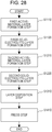
Fig. 28 is a flowchart illustrating a modification of a battery manufacturing method according to Embodiment 6; -
Fig. 29 illustrates the schematic configuration of abattery manufacturing apparatus 6100 according to Embodiment 6; -
Fig. 30 is a flowchart illustrating a modification of a battery manufacturing method according to Embodiment 6; -
Fig. 31 illustrates an example of a first-solid-electrolyte-layer formation step S1121 and a first-electrode-side cutting step S1122; -
Fig. 32 illustrates an example of a second-solid-electrolyte-layer formation step S1221 and a second-electrode-side cutting step S1222; -
Fig. 33 illustrates the schematic configuration of abattery manufacturing apparatus 7000 according to Embodiment 7; -
Fig. 34 is a flowchart illustrating a battery manufacturing method according to Embodiment 7; -
Fig. 35 illustrates an example of a first-active-material-layer formation step S2110 and a first-solid-electrolyte-layer formation step S2120; -
Fig. 36 illustrates an example of a second-active-material-layer formation step S2210 and a second-solid-electrolyte-layer formation step S2220; -
Fig. 37 illustrates an example of a layer disposition step S2310; -
Fig. 38 illustrates an example of a cutting step S2510; and -
Fig. 39 is a flowchart illustrating a modification of a battery manufacturing method according to Embodiment 7. - Hereinafter, embodiments according to the present disclosure will be described with referring to the drawings.
-
Fig. 1 illustrates the schematic configuration of abattery 1000 according to Embodiment 1. -
Fig. 1(a) is an x-z view (sectional view taken alongline 1A-1A) illustrating the schematic configuration of thebattery 1000 according to Embodiment 1. -
Fig. 1(b) is an x-y view (top perspective view) illustrating the schematic configuration of thebattery 1000 according to Embodiment 1. - The
battery 1000 according to Embodiment 1 includes afirst electrode layer 100 and asecond electrode layer 200. - The
second electrode layer 200 is disposed on thefirst electrode layer 100. Thesecond electrode layer 200 serves as a counter electrode for thefirst electrode layer 100. - The
first electrode layer 100 includes a firstcurrent collector 110, a firstactive material layer 120, and a firstsolid electrolyte layer 130. - The first
active material layer 120 is disposed to be in contact with the firstcurrent collector 110, and to occupy a smaller area than the firstcurrent collector 110. - The first
solid electrolyte layer 130 is disposed to be in contact with the firstcurrent collector 110 and the firstactive material layer 120, and to occupy the same area as the firstcurrent collector 110. - The first
active material layer 120 faces thesecond electrode layer 200 with the firstsolid electrolyte layer 130 therebetween. - The
first electrode layer 100 includes a peripheral portion including a firstrounded portion 140. - Such a configuration enables a reduction in the probability of coming off of the active material. Specifically, use of the
first electrode layer 100, which includes a peripheral portion including the firstrounded portion 140, enables a reduction in concentration of stress in the peripheral portion including the firstrounded portion 140 in the multilayer body including the firstcurrent collector 110 and the first solid electrolyte layer 130 (for example, dispersion of an impact force). This enables, in the peripheral portion including the firstrounded portion 140, a reduction in the probability of separation of the firstsolid electrolyte layer 130 from the first current collector 110 (or falling of the solid electrolyte from the first current collector 110). Thus, the firstsolid electrolyte layer 130, which is less likely to separate from the firstcurrent collector 110, is disposed to cover the firstactive material layer 120. As a result, for example, even when a corner of the battery being manufactured or used collides and impacts, the firstsolid electrolyte layer 130 enables a reduction in the damage caused on the firstactive material layer 120. In other words, the firstsolid electrolyte layer 130 enables a reduction in the probability of coming off of the active material from the firstactive material layer 120. This prevents short circuits within the battery that may be caused by movements of, within the battery, the active material coming off from the firstactive material layer 120. This enables enhanced reliability of the battery. - In the above-described configuration, the first
solid electrolyte layer 130, which is less likely to separate from the firstcurrent collector 110, is disposed to cover the firstactive material layer 120. In this case, even when the firstactive material layer 120 is disposed to extend close to the peripheral portion of the firstcurrent collector 110, the active material is prevented from coming off from the firstactive material layer 120. Thus, the firstactive material layer 120 can be disposed to occupy an area as large as possible, provided that the area is smaller than that of the firstcurrent collector 110. This enables an increase in the energy density of the battery. - In the present disclosure, the phrase "the solid electrolyte layer is disposed to occupy the same area as the current collector" means that the solid electrolyte layer is disposed to occupy substantially the same area as the current collector except for the error unavoidably occurring during the manufacture (for example, the solid electrolyte layer is disposed to have substantially the same shape as the current collector except for the error unavoidably occurring during the manufacture).
- Incidentally, as illustrated in
Fig. 1 , thesecond electrode layer 200 may include a secondcurrent collector 210, a secondactive material layer 220, and a secondsolid electrolyte layer 230. - The second
active material layer 220 is disposed to be in contact with the secondcurrent collector 210. - The second
solid electrolyte layer 230 is disposed to be in contact with the secondactive material layer 220. - The second
active material layer 220 faces the firstactive material layer 120 with the firstsolid electrolyte layer 130 and the secondsolid electrolyte layer 230 therebetween. - Such a configuration enables a reduction in the probability of contact between the first
current collector 110 and the secondcurrent collector 210. Specifically, a portion between the firstcurrent collector 110 and the secondcurrent collector 210, which face each other with the portion therebetween, is fixed with the firstsolid electrolyte layer 130 and the secondsolid electrolyte layer 230. For example, even when the firstcurrent collector 110 and the secondcurrent collector 210 are constituted by thin films, the presence of the firstsolid electrolyte layer 130 and the secondsolid electrolyte layer 230 enables the spacing between the firstcurrent collector 110 and the secondcurrent collector 210 to be maintained to have at least a predetermined distance (for example, equal to or longer than the total thickness of the firstsolid electrolyte layer 130 and the second solid electrolyte layer 230). This prevents the firstcurrent collector 110 and the secondcurrent collector 210 from coming into close proximity to each other. This prevents, for example, even when a plurality of battery cells are stacked, deformation of the firstcurrent collector 110 and the secondcurrent collector 210. Thus, for example, even when a plurality of battery cells are stacked, short circuits are prevented between the firstcurrent collector 110 and the secondcurrent collector 210. In addition, in another example that is an all-solid-state battery not having any separator between thefirst electrode layer 100 and thesecond electrode layer 200, the risk of short circuits caused by direct contact between the firstcurrent collector 110 and the secondcurrent collector 210 is reduced. - In addition, the above-described configuration eliminates the necessity of an additional member for insulation between the
first electrode layer 100 and the second electrode layer 200 (for example, an insulation spacer). This enables further simplification of and a reduction in the costs for battery manufacturing steps. - Incidentally, the first
solid electrolyte layer 130 and the secondsolid electrolyte layer 230 may be bonded together. - In such a configuration, the solid electrolyte layer provided by bonding together the first
solid electrolyte layer 130 and the secondsolid electrolyte layer 230 enables a reduction in the probability of short circuits due to pinholes that may be formed, for example, during manufacture, in the firstsolid electrolyte layer 130 and the secondsolid electrolyte layer 230. More specifically, in a region where the firstactive material layer 120 and the secondactive material layer 220 face each other, a bonding interface is provided that is formed by bonding together the firstsolid electrolyte layer 130 and the secondsolid electrolyte layer 230. In this case, the firstsolid electrolyte layer 130 and the secondsolid electrolyte layer 230 are each formed by a different manufacturing step, so that the positions of pinholes generated in the firstsolid electrolyte layer 130 do not coincide with the positions of pinholes generated in the secondsolid electrolyte layer 230. Thus, the secondsolid electrolyte layer 230 blocks, at the bonding interface, the pinholes generated in the firstsolid electrolyte layer 130. The firstsolid electrolyte layer 130 blocks, at the bonding interface, the pinholes generated in the secondsolid electrolyte layer 230. This enables a reduction in the probability of short circuits due to pinholes that may be generated during manufacture in the solid electrolyte layers. - Incidentally, as illustrated in
Fig. 1 , a partial region of a main surface (for example, a half or larger region of the main surface) of the firstsolid electrolyte layer 130 and the whole region of a main surface of the secondsolid electrolyte layer 230 may be bonded together. Alternatively, a partial region of a main surface (for example, a half or larger region of the main surface) of the firstsolid electrolyte layer 130 and a partial region of a main surface (for example, a half or larger region of the main surface) of the secondsolid electrolyte layer 230 may be bonded together. Alternatively, the whole region of a main surface of the firstsolid electrolyte layer 130 and the whole region of a main surface of the secondsolid electrolyte layer 230 may be bonded together. - The first
active material layer 120 contains an electrode material (for example, an active material). - The second
active material layer 220 contains a counter electrode material (for example, an active material). The counter electrode material constitutes the counter electrode for the above-described electrode material. - The first
solid electrolyte layer 130 and the secondsolid electrolyte layer 230 are solid electrolyte layers containing solid electrolytes. - Incidentally, the first
active material layer 120 may be a negative electrode active material layer. In this case, the electrode material is a negative electrode active material. The firstcurrent collector 110 is a negative electrode current collector. The firstsolid electrolyte layer 130 is a negative-electrode-side solid electrolyte layer. The secondactive material layer 220 is a positive electrode active material layer. The counter electrode material is a positive electrode active material. The secondcurrent collector 210 is a positive electrode current collector. The secondsolid electrolyte layer 230 is a positive-electrode-side solid electrolyte layer. - Alternatively, the first
active material layer 120 may be a positive electrode active material layer. In this case, the electrode material is a positive electrode active material. The firstcurrent collector 110 is a positive electrode current collector. The firstsolid electrolyte layer 130 is a positive-electrode-side solid electrolyte layer. The secondactive material layer 220 is a negative electrode active material layer. The counter electrode material is a negative electrode active material. The secondcurrent collector 210 is a negative electrode current collector. The secondsolid electrolyte layer 230 is a negative-electrode-side solid electrolyte layer. - The positive electrode current collector may be selected from publicly known positive electrode current collectors. The positive electrode current collector may be, for example, a metal foil. Examples of the material of the positive electrode current collector include aluminum, copper, stainless steel, nickel, platinum, gold, and alloys containing the foregoing.
- The positive electrode active material layer contains a positive electrode active material.
- The positive electrode active material may be selected from publicly known positive electrode active materials. When the
battery 1000 according to Embodiment 1 is constituted as a lithium ion secondary battery (storage battery), the positive electrode active material may be a compound that has a capability of occluding and releasing Li. For example, the positive electrode active material may be a compound containing lithium. Examples of the positive electrode active material include LiCoO2, LiNiO2, LiMn2O4, LiCoPO4, LiMnPO4, LiFePO4, LiNiPO4, and compounds obtained by substituting the transition metal of such a compound by one or two hetero elements (for example, LiNi1/3Co1/3Mn1/3O2, LiNi0.8Co0.15Al0.05O2, and LiNi0.5Mn1.5O2. - Incidentally, the positive electrode active material layer may be a positive electrode mixture layer containing a positive electrode active material and another material. Specifically, the positive electrode active material layer may contain a mixture of a positive electrode active material and a solid electrolyte. Alternatively, the positive electrode active material layer may contain, in addition to a positive electrode active material and a solid electrolyte, a conductive additive or a binder, for example.
- The positive electrode active material layer may be constituted by a plurality of layers. For example, the positive electrode active material layer may include, on its side in contact with the positive electrode current collector, a first layer. In this case, the positive electrode active material layer may include, on its side in contact with the positive-electrode-side solid electrolyte layer, a second layer. In this case, the first layer and the second layer may be different from each other in terms of constitutions (shape, thickness, and contained material).
- The positive-electrode-side solid electrolyte layer contains a positive-electrode-side solid electrolyte.
- The positive-electrode-side solid electrolyte may be selected from publicly known solid electrolytes. When the
battery 1000 according to Embodiment 1 is constituted as a lithium ion secondary battery (storage battery), the solid electrolyte may be a compound containing lithium. Examples of the solid electrolyte include Li3Zr2Si2PO12, Li7La3Zr2O12, Li5La3Ta2O12, Li1+xAlxTi2-x(PO4)3, Li1.5Ti1.7Al0.8P2.8Si0.2O12, La2/3-xLi3xTiO3, Li2S-SiS2-based glass and glass ceramics, Li2S-B2S3-based glass and glass ceramics, Li2S-P2S5-based glass and glass ceramics, Li3.25Ge0.25P0.75S4, and Li10GeP2S12. Other examples of the solid electrolyte include solid electrolytes obtained by adding an additive such as LiI or LixMOy (M: P, Si, Ge, B, Al, Ga, or In; x, y: natural numbers) to the above-described examples. Examples of the solid electrolyte include inorganic solid electrolytes (sulfide solid electrolytes or oxide solid electrolytes) and polymer solid electrolytes (for example, electrolytes obtained by dissolving a lithium salt in polyethylene oxide). - The positive-electrode-side solid electrolyte layer may be formed of a polymer electrolyte or a mixture of an inorganic solid electrolyte and a binder. In the positive-electrode-side solid electrolyte layer and the positive electrode active material layer, the solid electrolytes may be formed of the same material and the binders may be formed of the same material.
- The negative electrode current collector may be selected from publicly known negative electrode current collectors. The negative electrode current collector may be, for example, a metal foil. Examples of the material of the negative electrode current collector include aluminum, copper, stainless steel, nickel, platinum, gold, and alloys containing the foregoing.
- The negative electrode active material layer contains a negative electrode active material.
- The negative electrode active material may be selected from publicly known negative electrode active materials. When the
battery 1000 according to Embodiment 1 is constituted as a lithium ion secondary battery (storage battery), the negative electrode active material may be a compound that has a capability of occluding and releasing Li. For example, the negative electrode active material may be a metal compound or a carbonaceous material. Examples of the negative electrode active material include metal indium, metal lithium, carbonaceous materials (for example, graphite or hard carbon), Li4Ti5O12, Si, SiO, Sn, and SnO. - Incidentally, the negative electrode active material layer may be a negative electrode mixture layer containing a negative electrode active material and another material. Specifically, the negative electrode active material layer may contain a mixture of a negative electrode active material and a solid electrolyte. Alternatively, the negative electrode active material layer may contain, in addition to a negative electrode active material and a solid electrolyte, a conductive additive or a binder, for example. Incidentally, when the negative electrode active material layer is constituted by a foil formed of a metal that alloys with lithium, addition of the solid electrolyte and the like is not necessary.
- The negative-electrode-side solid electrolyte layer contains a negative-electrode-side solid electrolyte.
- The negative electrode active material layer may be constituted by a plurality of layers. For example, the negative electrode active material layer may include, on its side in contact with the negative electrode current collector, a first layer. In this case, the negative electrode active material layer may include, on its side in contact with the negative-electrode-side solid electrolyte layer, a second layer. In this case, the first layer and the second layer may be different from each other in terms of constitutions (shape, thickness, and contained material).
- The negative-electrode-side solid electrolyte may be selected from publicly known solid electrolytes. Examples of the material of the negative-electrode-side solid electrolyte include the above-described examples of the material of the positive-electrode-side solid electrolyte.
- The negative-electrode-side solid electrolyte layer may be formed of a polymer electrolyte or a mixture of an inorganic solid electrolyte and a binder. In the negative-electrode-side solid electrolyte layer and the negative electrode active material layer, the solid electrolytes may be formed of the same material and the binders may be formed of the same material.
- Examples of the conductive additives include carbonaceous materials (for example, acetylene black, Ketjenblack, or carbon nanotubes), and metal powders.
- The binders may be selected from publicly known polymer compounds. Examples of the binders include polyvinylidene fluoride (PVDF), polyvinylidene fluoride-hexafluoropropylene (PVDF-HFP), rubber-based resins, and elastomers.
- Incidentally, the positive-electrode-side solid electrolyte layer and the negative-electrode-side solid electrolyte layer may both contain a solid electrolyte of the same material, or may each contain a solid electrolyte of a different material.
- The positive-electrode-side solid electrolyte layer and the negative-electrode-side solid electrolyte layer may both contain a solid electrolyte at the same content (concentration), or may each contain a solid electrolyte at a different content (concentration).
- The positive-electrode-side solid electrolyte layer and the negative-electrode-side solid electrolyte layer may have the same thickness or different thicknesses.
- As illustrated in
Fig. 1 , the entirety of the negative electrode current collector may be positioned parallel to the positive electrode current collector. Specifically, the distance between the positive electrode current collector and the negative electrode current collector may be constant over the whole film region. Alternatively, a portion of the negative electrode current collector may be positioned parallel to the positive electrode current collector. - Incidentally, as illustrated in
Fig. 1 , thefirst electrode layer 100 may have a shape (in other words, the firstcurrent collector 110 and the firstsolid electrolyte layer 130 may have a shape) including a corner portion. - In this case, the corner portion of the
first electrode layer 100 may include a firstrounded portion 140. - Such a configuration enables a further reduction in the probability of coming off of the active material. Specifically, in the corner portion including the first
rounded portion 140 in the multilayer body including the firstcurrent collector 110 and the firstsolid electrolyte layer 130, a reduction in concentration of stress (for example, dispersion of an impact force) is achieved. This enables, in the corner portion including the firstrounded portion 140, a reduction in the probability of separation of the firstsolid electrolyte layer 130 from the first current collector 110 (or falling of the solid electrolyte from the first current collector 110). Thus, the firstsolid electrolyte layer 130, which is less likely to separate from the firstcurrent collector 110, is disposed to cover the firstactive material layer 120. As a result, for example, even when a corner of the battery being manufactured or used collides and impacts, the firstsolid electrolyte layer 130 enables a reduction in the damage caused on the firstactive material layer 120. In other words, the firstsolid electrolyte layer 130 enables a reduction in the probability of coming off of the active material from the firstactive material layer 120. This prevents short circuits within the battery that may be caused by movements of, within the battery, the active material coming off from the firstactive material layer 120. This enables further enhanced reliability of the battery. - In the above-described configuration, the first
solid electrolyte layer 130, which is less likely to separate from the firstcurrent collector 110, is disposed to cover the firstactive material layer 120. In this case, even when the firstactive material layer 120 is disposed to extend close to the corner portion of the firstcurrent collector 110, the active material is prevented from coming off from the firstactive material layer 120. Thus, the firstactive material layer 120 can be disposed to occupy an area as large as possible, provided that the area is smaller than that of the firstcurrent collector 110. This enables a further increase in the energy density of the battery. - In the present disclosure, the phrase "the shape of a predetermined layer" includes the meaning of "the shape of, in the main surface direction (x-y plane direction), a predetermined layer".
-
Fig. 2 illustrates the schematic configuration of abattery 1100 according to Embodiment 1. -
Fig. 2(a) is an x-z view (sectional view taken alongline 2A-2A) illustrating the schematic configuration of thebattery 1100 according to Embodiment 1. -
Fig. 2(b) is an x-y view (top perspective view) illustrating the schematic configuration of thebattery 1100 according to Embodiment 1. - In the
battery 1100 according to Embodiment 1, the firstrounded portion 140 is provided by cutting a corner portion of thefirst electrode layer 100 to form a straight line. - As described above, in the present disclosure, the term "rounded portion" (for example, the first
rounded portion 140, a secondrounded portion 240, and a rounded portion of an active material layer) includes the meaning of "a portion provided by cutting to form a curve" (namely, a round portion) as illustrated inFig. 1 , and the meaning of "a portion provided by cutting to form a straight line" (namely, a portion having an angle of 90° or larger) as illustrated inFig. 2 . -
Fig. 3 illustrates the schematic configuration of abattery 1200 according to Embodiment 1. -
Fig. 3(a) is an x-z view (sectional view taken alongline 3A-3A) illustrating the schematic configuration of thebattery 1200 according to Embodiment 1. -
Fig. 3(b) is an x-y view (top perspective view) illustrating the schematic configuration of thebattery 1200 according to Embodiment 1. - The
battery 1200 according to Embodiment 1 includes, in addition to the above-described features of thebattery 1000 according to Embodiment 1, the following feature. - Specifically, in the
battery 1200 according to Embodiment 1, thefirst electrode layer 100 has a polygon shape including a plurality of corner portions (for example, a triangular shape, a quadrangular shape or a rectangular shape). - In this case, each of the plurality of corner portions of the
first electrode layer 100 is formed to include the firstrounded portion 140. For example, in the example illustrated inFig. 3 , thefirst electrode layer 100 having a rectangular shape has four corner portions and all of these corner portions are formed to include a firstrounded portion 140a, a firstrounded portion 140b, a firstrounded portion 140c, and a firstrounded portion 140d. - Such a configuration enables a further reduction in the probability of coming off of the active material. Specifically, in each corner portion of the multilayer body including the first
current collector 110 and the firstsolid electrolyte layer 130, a reduction in concentration of stress (for example, dispersion of an impact force) is achieved. This enables, in each corner portion including the firstrounded portion 140, a reduction in the probability of separation of the firstsolid electrolyte layer 130 from the first current collector 110 (or falling of the solid electrolyte from the first current collector 110). Thus, the firstsolid electrolyte layer 130, which is less likely to separate from the firstcurrent collector 110, is disposed to cover the firstactive material layer 120. As a result, for example, even when a corner of the battery being manufactured or used collides and impacts, the firstsolid electrolyte layer 130 enables a reduction in the damage caused on the firstactive material layer 120. In other words, the firstsolid electrolyte layer 130 enables a reduction in the probability of coming off of the active material from the firstactive material layer 120. This prevents short circuits within the battery that may be caused by movements of, within the battery, the active material coming off from the firstactive material layer 120. This enables further enhanced reliability of the battery. - In the above-described configuration, the first
solid electrolyte layer 130, which is less likely to separate from the firstcurrent collector 110, is disposed to cover the firstactive material layer 120. In this case, even when the firstactive material layer 120 is disposed to extend close to all the corner portions of the firstcurrent collector 110, the active material is prevented from coming off from the firstactive material layer 120. Thus, the firstactive material layer 120 can be disposed to occupy an area as large as possible, provided that the area is smaller than that of the firstcurrent collector 110. This enables a further increase in the energy density of the battery. - In the case where a plurality of batteries according to Embodiment 1 are arranged, the above-described configuration in which such first electrode layers 100 have a polygon shape enables a denser arrangement of the batteries. Specifically, compared with a configuration employing first electrode layers 100 having a circular shape (for example, coin batteries), the configuration employing first electrode layers 100 having a polygon shape (for example, prismatic batteries) enables small spacing between batteries arranged in a planar direction. This enables a further increase in the energy density of a battery module (or a battery pack) constituted by arranging a plurality of batteries.
-
Fig. 4 illustrates the schematic configuration of abattery 1300 according to Embodiment 1. -
Fig. 4(a) is an x-z view (sectional view taken alongline 4A-4A) illustrating the schematic configuration of thebattery 1300 according to Embodiment 1. -
Fig. 4(b) is an x-y view (top perspective view) illustrating the schematic configuration of thebattery 1300 according to Embodiment 1. - The
battery 1300 according to Embodiment 1 includes, in addition to the above-described features of thebattery 1200 according to Embodiment 1, the following feature. - Specifically, in the
battery 1300 according to Embodiment 1, among the corner portions of the firstactive material layer 120, corner portions adjacent to the firstrounded portions 140 are formed to include a rounded portion. For example, in the example illustrated inFig. 4 , among the corner portions of the firstactive material layer 120, corner portions adjacent to the firstrounded portion 140a, the firstrounded portion 140b, the firstrounded portion 140c, and the firstrounded portion 140d are each formed to include a rounded portion. - Such a configuration enables a further reduction in the probability of coming off of the active material. Specifically, in the corner portions of the first
active material layer 120, a reduction in concentration of stress (for example, dispersion of an impact force) is achieved. This enables, in each corner portion including the firstrounded portion 140, a reduction in the probability of separation of the firstactive material layer 120 from the first current collector 110 (or falling of the firstactive material layer 120 from the first current collector 110). - Incidentally, the shape of such a rounded portion of the first
active material layer 120 may be selected from the above-described shapes for the firstrounded portion 140. -
Figs. 5A to 5E are x-y views (top perspective views) illustrating other examples of the shapes of the firstcurrent collector 110 and the firstactive material layer 120. - As illustrated in
Fig. 5A , among the corner portions of the firstcurrent collector 110, two diagonally opposite corner portions may each be formed to include the firstrounded portion 140. In this case, the firstactive material layer 120 may have the same shape as the firstcurrent collector 110. - Alternatively, as illustrated in
Fig. 5B , among the corner portions of the firstcurrent collector 110, two adjacent corner portions may each be formed to include the firstrounded portion 140. In this case, the firstactive material layer 120 may have the same shape as the firstcurrent collector 110. - Alternatively, as illustrated in
Figs. 5C to 5E , among the corner portions of the firstcurrent collector 110, all the corner portions may be cut to have straight line shapes, to thereby include four firstrounded portions 140. In this case, as illustrated inFig. 5C , the firstactive material layer 120 may not have any rounded portion. Alternatively, as illustrated inFig. 5D , the firstactive material layer 120 may have the same shape as the firstcurrent collector 110. Alternatively, as illustrated inFig. 5E , all the corner portions of the firstactive material layer 120 may be cut to have curved shapes, to thereby include four rounded portions. -
Fig. 6 illustrates the schematic configuration of abattery 1400 according to Embodiment 1. -
Fig. 6(a) is an x-z view (sectional view taken alongline 6A-6A) illustrating the schematic configuration of thebattery 1400 according to Embodiment 1. -
Fig. 6(b) is an x-y view (top perspective view) illustrating the schematic configuration of thebattery 1400 according to Embodiment 1. - The
battery 1400 according to Embodiment 1 includes, in addition to the above-described features of thebattery 1000 according to Embodiment 1, the following feature. - Specifically, in the
battery 1400 according to Embodiment 1, thesecond electrode layer 200 includes a secondcurrent collector 210, a secondactive material layer 220, and a secondsolid electrolyte layer 230. - The second
active material layer 220 is disposed to be in contact with the secondcurrent collector 210, and to occupy a smaller area than the secondcurrent collector 210. - The second
solid electrolyte layer 230 is disposed to be in contact with the secondcurrent collector 210 and the secondactive material layer 220, and to occupy the same area as the secondcurrent collector 210. - The second
active material layer 220 faces the firstactive material layer 120 with the firstsolid electrolyte layer 130 and the secondsolid electrolyte layer 230 therebetween. - The first
solid electrolyte layer 130 and the secondsolid electrolyte layer 230 are bonded together. - The peripheral portion of the
second electrode layer 200 is formed to include a secondrounded portion 240. - Such a configuration enables a further reduction in the probability of coming off of the active material. Specifically, use of the
second electrode layer 200, which includes the peripheral portion including the secondrounded portion 240, enables a reduction in concentration of stress (for example, dispersion of an impact force) in the peripheral portion including the secondrounded portion 240 in the multilayer body including the secondcurrent collector 210 and the secondsolid electrolyte layer 230. This enables, in the peripheral portion including the secondrounded portion 240, a reduction in the probability of separation of the secondsolid electrolyte layer 230 from the second current collector 210 (or falling of the solid electrolyte from the second current collector 210). Thus, the secondsolid electrolyte layer 230, which is less likely to separate from the secondcurrent collector 210, is disposed to cover the secondactive material layer 220. As a result, for example, even when a corner of the battery being manufactured or used collides and impacts, the secondsolid electrolyte layer 230 enables a reduction in the damage caused on the secondactive material layer 220. In other words, the secondsolid electrolyte layer 230 enables a reduction in the probability of coming off of the active material from the secondactive material layer 220. This prevents short circuits within the battery that may be caused by movements of, within the battery, the active material coming off from the secondactive material layer 220. This enables further enhanced reliability of the battery. - In the above-described configuration, the second
solid electrolyte layer 230, which is less likely to separate from the secondcurrent collector 210, is disposed to cover the secondactive material layer 220. In this case, even when the secondactive material layer 220 is disposed to extend close to the peripheral portion of the secondcurrent collector 210, the active material is prevented from coming off from the secondactive material layer 220. Thus, the secondactive material layer 220 can be disposed to occupy an area as large as possible, provided that the area is smaller than that of the secondcurrent collector 210. This enables a further increase in the energy density of the battery. - Incidentally, as illustrated in
Fig. 6 , the shape of the second electrode layer 200 (in other words, the shapes of the secondcurrent collector 210 and the second solid electrolyte layer 230) may include corner portions. - In this case, a corner portion of the
second electrode layer 200 may be formed to include the secondrounded portion 240. - Such a configuration enables a further reduction in the probability of coming off of the active material. Specifically, in the corner portion including the second
rounded portion 240 in the multilayer body including the secondcurrent collector 210 and the secondsolid electrolyte layer 230, a reduction in concentration of stress (for example, dispersion of an impact force) is achieved. This enables, in the corner portion including the secondrounded portion 240, a reduction in the probability of separation of the secondsolid electrolyte layer 230 from the second current collector 210 (or falling of the solid electrolyte from the second current collector 210). Thus, the secondsolid electrolyte layer 230, which is less likely to separate from the secondcurrent collector 210, is disposed to cover the secondactive material layer 220. As a result, for example, even when a corner of the battery being manufactured or used collides and impacts, the secondsolid electrolyte layer 230 enables a reduction in the damage caused on the secondactive material layer 220. In other words, the secondsolid electrolyte layer 230 enables a reduction in the probability of coming off of the active material from the secondactive material layer 220. This prevents short circuits within the battery that may be caused by movements of, within the battery, the active material coming off from the secondactive material layer 220. This enables further enhanced reliability of the battery. - In the above-described configuration, the second
solid electrolyte layer 230, which is less likely to separate from the secondcurrent collector 210, is disposed to cover the secondactive material layer 220. In this case, even when the secondactive material layer 220 is disposed to extend close to the corner portion of the secondcurrent collector 210, the active material is prevented from coming off from the secondactive material layer 220. Thus, the secondactive material layer 220 can be disposed to occupy an area as large as possible, provided that the area is smaller than that of the secondcurrent collector 210. This enables a further increase in the energy density of the battery. - Incidentally, the shape of the second
rounded portion 240 may be selected from the above-described shapes for the firstrounded portion 140. -
Fig. 7 illustrates the schematic configuration of abattery 1500 according to Embodiment 1. -
Fig. 7(a) is an x-z view (sectional view taken alongline 7A-7A) illustrating the schematic configuration of thebattery 1500 according to Embodiment 1. -
Fig. 7(b) is an x-y view (top perspective view) illustrating the schematic configuration of thebattery 1500 according to Embodiment 1. - The
battery 1500 according to Embodiment 1 includes, in addition to the above-described features of thebattery 1200 according to Embodiment 1, the following feature. - Specifically, in the
battery 1500 according to Embodiment 1, thesecond electrode layer 200 has a polygon shape including a plurality of corner portions (for example, a triangular shape, a quadrangular shape or a rectangular shape). - In this case, all of the corner portions of the
second electrode layer 200 are formed to include secondrounded portions 240. For example, in the example illustrated inFig. 7 , all of the four corner portions of thesecond electrode layer 200, which has a rectangular shape, are formed to include a secondrounded portion 240a, a secondrounded portion 240b, a secondrounded portion 240c, and a secondrounded portion 240d. - Such a configuration enables a further reduction in the probability of coming off of the active material. Specifically, in all the corner portions of the multilayer body including the second
current collector 210 and the secondsolid electrolyte layer 230, a reduction in concentration of stress (for example, dispersion of an impact force) is achieved. This enables a reduction in the probability of, in all the corner portions including the secondrounded portions 240, separation of the secondsolid electrolyte layer 230 from the second current collector 210 (or falling of the solid electrolyte from the second current collector 210). Thus, the secondsolid electrolyte layer 230, which is less likely to separate from the secondcurrent collector 210, is disposed to cover the secondactive material layer 220. As a result, for example, even when a corner of the battery being manufactured or used collides and impacts, the secondsolid electrolyte layer 230 enables a reduction in the damage caused on the secondactive material layer 220. In other words, the secondsolid electrolyte layer 230 enables a reduction in the probability of coming off of the active material from the secondactive material layer 220. This prevents short circuits within the battery that may be caused by movements of, within the battery, the active material coming off from the secondactive material layer 220. This enables further enhanced reliability of the battery. - In the above-described configuration, the second
solid electrolyte layer 230, which is less likely to separate from the secondcurrent collector 210, is disposed to cover the secondactive material layer 220. In this case, even when the secondactive material layer 220 is disposed to extend close to all the corner portions of the secondcurrent collector 210, the active material is prevented from coming off from the secondactive material layer 220. Thus, the secondactive material layer 220 can be disposed to occupy an area as large as possible, provided that the area is smaller than that of the secondcurrent collector 210. This enables a further increase in the energy density of the battery. - In the case where a plurality of batteries according to Embodiment 1 are arranged, the above-described configuration in which such second electrode layers 200 have a polygon shape enables a denser arrangement of the batteries. Specifically, compared with a configuration employing second electrode layers 200 having a circular shape (for example, coin batteries), the configuration employing second electrode layers 200 having a polygon shape (for example, prismatic batteries) enables small spacing between batteries arranged in a planar direction. This enables a further increase in the energy density of a battery module (or a battery pack) constituted by arranging a plurality of batteries.
-
Fig. 8 illustrates the schematic configuration of abattery 1600 according to Embodiment 1. -
Fig. 8(a) is an x-z view (sectional view taken alongline 8A-8A) illustrating the schematic configuration of thebattery 1600 according to Embodiment 1. -
Fig. 8(b) is an x-y view (top perspective view) illustrating the schematic configuration of thebattery 1600 according to Embodiment 1. - The
battery 1600 according to Embodiment 1 includes, in addition to the above-described features of thebattery 1500 according to Embodiment 1, the following feature. - Specifically, in the
battery 1600 according to Embodiment 1, among the corner portions of the secondactive material layer 220, the corner portions adjacent to the secondrounded portions 240 are formed to include rounded portions. For example, in the example illustrated inFig. 8 , among the corner portions of the secondactive material layer 220, corner portions adjacent to the secondrounded portion 240a, the secondrounded portion 240b, the secondrounded portion 240c, and the secondrounded portion 240d are formed to include rounded portions. - Such a configuration enables a further reduction in the probability of coming off of the active material. Specifically, in the corner portions of the second
active material layer 220, a reduction in concentration of stress (for example, dispersion of an impact force) is achieved. This enables, in the corner portions including the secondrounded portions 240, a reduction in the probability of separation of the secondactive material layer 220 from the second current collector 210 (or falling of the secondactive material layer 220 from the second current collector 210). - Incidentally, in the
battery 1600 according to Embodiment 1, among the corner portions of the firstactive material layer 120, corner portions adjacent to the firstrounded portions 140 may be formed to include rounded portions. For example, in the example illustrated inFig. 8 , among the corner portions of the firstactive material layer 120, corner portions adjacent to the firstrounded portion 140a, the firstrounded portion 140b, the firstrounded portion 140c, and the firstrounded portion 140d are formed to include rounded portions. - Incidentally, the shape of the rounded portions of the second
active material layer 220 may be selected from the above-described shapes for the firstrounded portion 140. - Other examples of the shapes of the second
current collector 210 and the secondactive material layer 220 include the shapes illustrated inFigs. 5A to 5E as other examples of the shapes of the firstcurrent collector 110 and the firstactive material layer 120. -
Fig. 9 illustrates the schematic configuration of abattery 1700 according to Embodiment 1. -
Fig. 9(a) is an x-z view (sectional view taken alongline 9A-9A) illustrating the schematic configuration of thebattery 1700 according to Embodiment 1. -
Fig. 9(b) is an x-y view (top perspective view) illustrating the schematic configuration of thebattery 1700 according to Embodiment 1. - The
battery 1700 according to Embodiment 1 includes, in addition to the above-described features of thebattery 1600 according to Embodiment 1, the following feature. - Specifically, in the
battery 1700 according to Embodiment 1, thefirst electrode layer 100 has a circular shape (for example, an elliptic shape, a perfect circle shape, or a coin shape). In this case, the firstrounded portion 140 refers to the edge portion (peripheral portion) of the circularfirst electrode layer 100. - Such a configuration enables a further reduction in the probability of coming off of the active material. Specifically, use of the circular
first electrode layer 100 enables, over the whole peripheral portion of the multilayer body including the firstcurrent collector 110 and the firstsolid electrolyte layer 130, a reduction in concentration of stress (for example, dispersion of an impact force). This enables, over the whole peripheral portion, a reduction in the probability of separation of the firstsolid electrolyte layer 130 from the first current collector 110 (or falling of the solid electrolyte from the first current collector 110). Thus, the firstsolid electrolyte layer 130, which is less likely to separate from the firstcurrent collector 110, is disposed to cover the firstactive material layer 120. As a result, for example, even when a corner of the battery being manufactured or used collides and impacts, the firstsolid electrolyte layer 130 enables a reduction in the damage caused on the firstactive material layer 120. In other words, the firstsolid electrolyte layer 130 enables a reduction in the probability of coming off of the active material from the firstactive material layer 120. This prevents short circuits within the battery that may be caused by movements of, within the battery, the active material coming off from the firstactive material layer 120. This enables further enhanced reliability of the battery. - In the above-described configuration, the first
solid electrolyte layer 130, which is less likely to separate from the firstcurrent collector 110, is disposed to cover the firstactive material layer 120. In this case, even when the firstactive material layer 120 is disposed to extend close to the whole peripheral portion of the firstcurrent collector 110, the active material is prevented from coming off from the firstactive material layer 120. Thus, the firstactive material layer 120 can be disposed to occupy an area as large as possible, provided that the area is smaller than that of the firstcurrent collector 110. This enables a further increase in the energy density of the battery. - Incidentally, in the
battery 1700 according to Embodiment 1, thesecond electrode layer 200 may have a circular shape (for example, an elliptic shape, a perfect circle shape, or a coin shape). In this case, the secondrounded portion 240 refers to the edge portion (peripheral portion) of the circularsecond electrode layer 200. - Such a configuration enables a further reduction in the probability of coming off of the active material. Specifically, use of the circular
second electrode layer 200 enables, over the whole peripheral portion of the multilayer body including the secondcurrent collector 210 and the secondsolid electrolyte layer 230, a reduction in concentration of stress (for example, dispersion of an impact force). This enables, over the whole peripheral portion, a reduction in the probability of separation of the secondsolid electrolyte layer 230 from the second current collector 210 (or falling of the solid electrolyte from the second current collector 210). Thus, the secondsolid electrolyte layer 230, which is less likely to separate from the secondcurrent collector 210, is disposed to cover the secondactive material layer 220. As a result, for example, even when a corner of the battery being manufactured or used collides and impacts, the secondsolid electrolyte layer 230 enables a reduction in the damage caused on the secondactive material layer 220. In other words, the secondsolid electrolyte layer 230 enables a reduction in the probability of coming off of the active material from the secondactive material layer 220. This prevents short circuits within the battery that may be caused by movements of, within the battery, the active material coming off from the secondactive material layer 220. This enables further enhanced reliability of the battery. - In the above-described configuration, the second
solid electrolyte layer 230, which is less likely to separate from the secondcurrent collector 210, is disposed to cover the secondactive material layer 220. In this case, even when the secondactive material layer 220 is disposed to extend close to the whole peripheral portion of the secondcurrent collector 210, the active material is prevented from coming off from the secondactive material layer 220. Thus, the secondactive material layer 220 can be disposed to occupy an area as large as possible, provided that the area is smaller than that of the secondcurrent collector 210. This enables a further increase in the energy density of the battery. - Incidentally, as illustrated in
Fig. 9 , in thebattery 1700 according to Embodiment 1, one or both of the firstactive material layer 120 and the secondactive material layer 220 may have a circular shape (for example, an elliptic shape, a perfect circle shape, or a coin shape). - Such a configuration enables a further reduction in the probability of coming off of the active material. Specifically, over the whole peripheral portion of the first
active material layer 120 and the secondactive material layer 220, a reduction in concentration of stress (for example, dispersion of an impact force) is achieved. This enables, over the whole peripheral portion, a reduction in the probability of separation of the firstactive material layer 120 from the first current collector 110 (or falling of the firstactive material layer 120 from the first current collector 110), and a reduction in the probability of separation of the secondactive material layer 220 from the second current collector 210 (or falling of the secondactive material layer 220 from the second current collector 210). - Incidentally, in Embodiment 1, the first
active material layer 120 may be disposed to occupy a larger area than the secondactive material layer 220. - In this case, the second
active material layer 220 may be disposed within the area of the firstactive material layer 120. - Such a configuration enables suppression of precipitation of metal (for example, lithium) on the
first electrode layer 100. This prevents short circuits between thefirst electrode layer 100 and thesecond electrode layer 200 due to precipitation of metal. For example, in the case of a lithium ion battery employing a carbonaceous material or metal lithium for the negative electrode, the negative-electrode-side potential during charge decreases to around a potential at which lithium ions precipitate as metal. Thus, for example, when the battery is charged or rapidly charged in a low-temperature environment, the negative electrode active material may not exhibit a sufficiently high occlusion rate for lithium ions. In this case, lithium ions may precipitate as metal lithium. This precipitation of metal lithium particularly tends to occur at an edge portion, where current concentrates. Thus, the battery is constituted such that, in a perspective view of the battery viewed on a main surface side of the battery, the main surface of the firstactive material layer 120 has a shape contained within the main surface of the secondactive material layer 220. This enables suppression of precipitation of metal lithium when the firstactive material layer 120 is a negative electrode active material layer. - Hereinafter, Embodiment 2 will be described. Some descriptions overlapping those described in Embodiment 1 above will be appropriately omitted.
-
Fig. 10 illustrates the schematic configuration of abattery 2000 according to Embodiment 2. -
Fig. 10(a) is an x-z view (sectional view taken alongline 10A-10A) illustrating the schematic configuration of thebattery 2000 according to Embodiment 2. -
Fig. 10(b) is an x-y view (top perspective view) illustrating the schematic configuration of thebattery 2000 according to Embodiment 2. - The
battery 2000 according to Embodiment 2 includes, in addition to the above-described features of thebattery 1400 according to Embodiment 1, the following feature. - Specifically, in the
battery 2000 according to Embodiment 2, the firstrounded portion 140 and the secondrounded portion 240 have the same shape. - In this case, the
first electrode layer 100 and thesecond electrode layer 200 are disposed on each other, and the edge portion of the firstrounded portion 140 and the edge portion of the secondrounded portion 240 are located to coincide with each other. - Such a configuration enables stronger bonding between the first
solid electrolyte layer 130 and the secondsolid electrolyte layer 230. Specifically, thefirst electrode layer 100 and thesecond electrode layer 200 are disposed on each other, and the edge portion of the firstrounded portion 140 and the edge portion of the secondrounded portion 240 are located to coincide with each other. In this case, no stepped structure is formed in the position of the edge portion of the firstrounded portion 140 and the edge portion of the secondrounded portion 240. This enables, in the position of the edge portion of the firstrounded portion 140 and the edge portion of the secondrounded portion 240, a reduction in the probability of separation of the secondsolid electrolyte layer 230 from the firstsolid electrolyte layer 130. This enables further suppression of coming off of a battery member (for example, coming off of the active material) due to separation of the secondsolid electrolyte layer 230 from the firstsolid electrolyte layer 130. - Incidentally, in the present disclosure, the phrase "the shape of the rounded portion" includes the meaning of "the shape, in the main surface direction (x-y plane direction), of a predetermined layer including the rounded portion".
- In the present disclosure, the phrase "two rounded portions have the same shape" includes the meaning of "two predetermined layers including two rounded portions have the same shape in the main surface direction (x-y plane direction)".
- Incidentally, in the present disclosure, as illustrated in
Fig. 10 , the phrase "the edge portion of the firstrounded portion 140 and the edge portion of the secondrounded portion 240 are located to coincide with each other" includes the meaning of, for example, "the curved cut portion forming the firstrounded portion 140 and the curved cut portion forming the secondrounded portion 240 are disposed to overlap such that no stepped structure is formed". - In the present disclosure, the phrase "the edge portion of the first
rounded portion 140 and the edge portion of the secondrounded portion 240 are located to coincide with each other" also includes the meaning of, for example, "the straight cut portion and the 90° or larger corner portion that form the firstrounded portion 140 and the straight cut portion and the 90° or larger corner portion that form the secondrounded portion 240 are disposed to overlap such that no stepped structure is formed". - In the present disclosure, the phrase "two predetermined edge portions are located to coincide with each other" includes the meaning of, for example, "two predetermined edge portions are located to coincide with each other except for unavoidable 'deviation' due to manufacture error". In this case, the phrase "two predetermined edge portions are disposed to overlap such that no stepped structure is formed" includes the meaning of "two predetermined edge portions are disposed to overlap such that no stepped structure is formed except for stepped structures caused by unavoidable 'deviation' due to manufacture error".
-
Fig. 11 illustrates the schematic configuration of abattery 2100 according to Embodiment 2. -
Fig. 11(a) is an x-z view (sectional view taken alongline 11A-11A) illustrating the schematic configuration of thebattery 2100 according to Embodiment 2. -
Fig. 11(b) is an x-y view (top perspective view) illustrating the schematic configuration of thebattery 2100 according to Embodiment 2. - The
battery 2100 according to Embodiment 2 includes, in addition to the above-described features of thebattery 2000 according to Embodiment 2, the following feature. - Specifically, in the
battery 2100 according to Embodiment 2, thefirst electrode layer 100 and thesecond electrode layer 200 have the same shape. - In this case, the
first electrode layer 100 and thesecond electrode layer 200 are disposed on each other, and the edge portion of thefirst electrode layer 100 and the edge portion of thesecond electrode layer 200 are located to coincide with each other. - Such a configuration enables stronger bonding between the first
solid electrolyte layer 130 and the secondsolid electrolyte layer 230. Specifically, thefirst electrode layer 100 and thesecond electrode layer 200 are disposed on each other, and the edge portion of thefirst electrode layer 100 and the edge portion of thesecond electrode layer 200 are located to coincide with each other. In this case, no stepped structure is formed in the position of the edge portion of thefirst electrode layer 100 and the edge portion of thesecond electrode layer 200. This enables, in the position of the edge portion of thefirst electrode layer 100 and the edge portion of thesecond electrode layer 200, a reduction in the probability of separation of the secondsolid electrolyte layer 230 from the firstsolid electrolyte layer 130. This enables further suppression of coming off of a battery member (for example, coming off of the active material) due to separation of the secondsolid electrolyte layer 230 from the firstsolid electrolyte layer 130. - Incidentally, in the present disclosure, as illustrated in
Fig. 11 , the phrase "the edge portion of thefirst electrode layer 100 and the edge portion of thesecond electrode layer 200 are located to coincide with each other" includes the meaning of, for example, "the straight edge portions, the corner portions, and the rounded portion of thefirst electrode layer 100, and the straight edge portions, the corner portions, and the rounded portion of thesecond electrode layer 200 are disposed to overlap such that no stepped structure is formed". -
Fig. 12 illustrates the schematic configuration of abattery 2200 according to Embodiment 2. -
Fig. 12(a) is an x-z view (sectional view taken alongline 12A-12A) illustrating the schematic configuration of thebattery 2200 according to Embodiment 2. -
Fig. 12(b) is an x-y view (top perspective view) illustrating the schematic configuration of thebattery 2200 according to Embodiment 2. - The
battery 2200 according to Embodiment 2 includes, in addition to the above-described features of thebattery 2100 according to Embodiment 2, the following feature. - Specifically, in the
battery 2200 according to Embodiment 2, all the corner portions of thefirst electrode layer 100 are formed to include the first rounded portions 140 (140a, 140b, 140c, and 140d). - In addition, all the corner portions of the
second electrode layer 200 are formed to include the second rounded portions 240 (240a, 240b, 240c, and 240d). - Incidentally, in the present disclosure, as illustrated in
Fig. 12 , the phrase "the edge portion of thefirst electrode layer 100 and the edge portion of thesecond electrode layer 200 are located to coincide with each other" includes the meaning of, for example, "the straight edge portions and all the rounded portions of thefirst electrode layer 100 and the straight edge portions and all the rounded portions of thesecond electrode layer 200 are disposed to overlap such that no stepped structure is formed". -
Fig. 13 illustrates the schematic configuration of abattery 2300 according to Embodiment 2. -
Fig. 13(a) is an x-z view (sectional view taken alongline 13A-13A) illustrating the schematic configuration of thebattery 2300 according to Embodiment 2. -
Fig. 13(b) is an x-y view (top perspective view) illustrating the schematic configuration of thebattery 2300 according to Embodiment 2. - The
battery 2300 according to Embodiment 2 includes, in addition to the above-described features of thebattery 2000 according to Embodiment 2, the following feature. - Specifically, in the
battery 2300 according to Embodiment 2, thefirst electrode layer 100 has a circular shape (for example, an elliptic shape, a perfect circle shape, or a coin shape). - The
second electrode layer 200 has a circular shape (for example, an elliptic shape, a perfect circle shape, or a coin shape). - Incidentally, in the present disclosure, as illustrated in
Fig. 13 , the phrase "the edge portion of thefirst electrode layer 100 and the edge portion of thesecond electrode layer 200 are located to coincide with each other" includes the meaning of, for example, "the curved edge portion (peripheral portion) forming the firstrounded portion 140 of thefirst electrode layer 100 and the curved edge portion (peripheral portion) forming the secondrounded portion 240 of thesecond electrode layer 200 are disposed to overlap such that no stepped structure is formed". - Incidentally, as illustrated in
Fig. 13 , in thebattery 2300 according to Embodiment 2, one or both of the firstactive material layer 120 and the secondactive material layer 220 may have a circular shape (for example, an elliptic shape, a perfect circle shape, or a coin shape). - Such a configuration enables a further reduction in the probability of coming off of the active material. Specifically, over the whole peripheral portion of the first
active material layer 120 and the secondactive material layer 220, a reduction in concentration of stress (for example, dispersion of an impact force) is achieved. This enables, over the whole peripheral portion, a reduction in the probability of separation of the firstactive material layer 120 from the first current collector 110 (or falling of the firstactive material layer 120 from the first current collector 110), and a reduction in the probability of separation of the secondactive material layer 220 from the second current collector 210 (or falling of the secondactive material layer 220 from the second current collector 210). - Hereinafter, Embodiment 3 will be described. Some descriptions overlapping those described in Embodiment 1 or 2 above will be appropriately omitted.
-
Fig. 14 illustrates the schematic configuration of abattery 3000 according to Embodiment 3. -
Fig. 14(a) is an x-z view (sectional view taken alongline 14A-14A) illustrating the schematic configuration of thebattery 3000 according to Embodiment 3. -
Fig. 14(b) is an x-y view (top perspective view) illustrating the schematic configuration of thebattery 3000 according to Embodiment 3. - The
battery 3000 according to Embodiment 3 includes, in addition to the above-described features of thebattery 1000 according to Embodiment 1, the following feature. - Specifically, in the
battery 3000 according to Embodiment 3, thesecond electrode layer 200 includes a secondcurrent collector 210 and a secondactive material layer 220. - The second
active material layer 220 is disposed to be in contact with the secondcurrent collector 210, and to occupy a smaller area than the secondcurrent collector 210. - The first
solid electrolyte layer 130 is disposed to be in contact with the secondcurrent collector 210 and the secondactive material layer 220, and to occupy the same area as the secondcurrent collector 210. - The second
active material layer 220 faces the firstactive material layer 120 with the firstsolid electrolyte layer 130 therebetween. - The peripheral portion of the second
current collector 210 is formed to include the secondrounded portion 240. - The first
rounded portion 140 and the secondrounded portion 240 have the same shape. - The
first electrode layer 100 and thesecond electrode layer 200 are disposed on each other, and the edge portion of the firstrounded portion 140 and the edge portion of the secondrounded portion 240 are located to coincide with each other. - Such a configuration enables stronger bonding between the first
solid electrolyte layer 130 and the secondcurrent collector 210. Specifically, thefirst electrode layer 100 and thesecond electrode layer 200 are disposed on each other, and the edge portion of the firstrounded portion 140 and the edge portion of the secondrounded portion 240 are located to coincide with each other. In this case, no stepped structure is formed in the position of the edge portion of the firstrounded portion 140 and the edge portion of the secondrounded portion 240. This enables, in the position of the edge portion of the firstrounded portion 140 and the edge portion of the secondrounded portion 240, a reduction in the probability of separation of the secondcurrent collector 210 from the firstsolid electrolyte layer 130. This enables further suppression of coming off of a battery member (for example, coming off of the active material) due to separation of the secondcurrent collector 210 from the firstsolid electrolyte layer 130. -
Fig. 15 illustrates the schematic configuration of abattery 3100 according to Embodiment 3. -
Fig. 15(a) is an x-z view (sectional view taken alongline 15A-15A) illustrating the schematic configuration of thebattery 3100 according to Embodiment 3. -
Fig. 15(b) is an x-y view (top perspective view) illustrating the schematic configuration of thebattery 3100 according to Embodiment 3. - The
battery 3100 according to Embodiment 3 includes, in addition to the above-described features of thebattery 3000 according to Embodiment 3, the following feature. - Specifically, in the
battery 3100 according to Embodiment 3, thefirst electrode layer 100 and thesecond electrode layer 200 have the same shape. - The
first electrode layer 100 and thesecond electrode layer 200 are disposed on each other, and the edge portion of thefirst electrode layer 100 and the edge portion of thesecond electrode layer 200 are located to coincide with each other. - Such a configuration enables stronger bonding between the first
solid electrolyte layer 130 and the secondcurrent collector 210. Specifically, thefirst electrode layer 100 and thesecond electrode layer 200 are disposed on each other, and the edge portion of thefirst electrode layer 100 and the edge portion of thesecond electrode layer 200 are located to coincide with each other. In this case, no stepped structure is formed in the position of the edge portion of thefirst electrode layer 100 and the edge portion of thesecond electrode layer 200. This enables, in the position of the edge portion of thefirst electrode layer 100 and the edge portion of thesecond electrode layer 200, a reduction in the probability of separation of the secondcurrent collector 210 from the firstsolid electrolyte layer 130. This enables further suppression of coming off of a battery member (for example, coming off of the active material) due to separation of the secondcurrent collector 210 from the firstsolid electrolyte layer 130. -
Fig. 16 illustrates the schematic configuration of abattery 3200 according to Embodiment 3. -
Fig. 16(a) is an x-z view (sectional view taken alongline 16A-16A) illustrating the schematic configuration of thebattery 3200 according to Embodiment 3. -
Fig. 16(b) is an x-y view (top perspective view) illustrating the schematic configuration of thebattery 3200 according to Embodiment 3. - The
battery 3200 according to Embodiment 3 includes, in addition to the above-described features of thebattery 3100 according to Embodiment 3, the following feature. - Specifically, in the
battery 3200 according to Embodiment 3, thefirst electrode layer 100 and thesecond electrode layer 200 have a circular shape. - Such a configuration enables stronger bonding between the first
solid electrolyte layer 130 and the secondcurrent collector 210. Specifically, thefirst electrode layer 100 and thesecond electrode layer 200 are disposed on each other, and the edge portion of the circularfirst electrode layer 100 and the edge portion of the circularsecond electrode layer 200 are located to coincide with each other. In this case, in the position over the whole peripheral portion of thefirst electrode layer 100 and thesecond electrode layer 200, no stepped structure is formed. This enables, in the position over the whole peripheral portion of thefirst electrode layer 100 and thesecond electrode layer 200, a reduction in the probability of separation of the secondcurrent collector 210 from the firstsolid electrolyte layer 130. This enables further suppression of coming off of a battery member (for example, coming off of the active material) due to separation of the secondcurrent collector 210 from the firstsolid electrolyte layer 130. - Incidentally, as illustrated in
Fig. 16 , in thebattery 3200 according to Embodiment 3, one or both of the firstactive material layer 120 and the secondactive material layer 220 may have a circular shape (for example, an elliptic shape, a perfect circle shape, or a coin shape). - Such a configuration enables a further reduction in the probability of coming off of the active material. Specifically, over the whole peripheral portion of the first
active material layer 120 and the secondactive material layer 220, a reduction in concentration of stress (for example, dispersion of an impact force) is achieved. This enables, over the whole peripheral portion, a reduction in the probability of separation of the firstactive material layer 120 from the first current collector 110 (or falling of the firstactive material layer 120 from the first current collector 110), and a reduction in the probability of separation of the secondactive material layer 220 from the second current collector 210 (or falling of the secondactive material layer 220 from the second current collector 210). - Hereinafter, Embodiment 4 will be described. Some descriptions overlapping any of those described in Embodiments 1 to 3 above will be appropriately omitted.
-
Fig. 17 illustrates the schematic configuration of abattery 4000 according to Embodiment 4. -
Fig. 17(a) is an x-z view (sectional view taken alongline 17A-17A) illustrating the schematic configuration of thebattery 4000 according to Embodiment 4. -
Fig. 17(b) is an x-y view (top perspective view) illustrating the schematic configuration of thebattery 4000 according to Embodiment 4. - The
battery 4000 according to Embodiment 4 includes, in addition to the above-described features of thebattery 1000 according to Embodiment 1, the following feature. - Specifically, the
battery 4000 according to Embodiment 4 further includes athird electrode layer 300. - The
third electrode layer 300 is disposed on thefirst electrode layer 100. Thethird electrode layer 300 serves as the counter electrode for thefirst electrode layer 100. - The
third electrode layer 300 includes a thirdcurrent collector 310, a thirdactive material layer 320, and a thirdsolid electrolyte layer 330. - The first
current collector 110 and the thirdcurrent collector 310 are electrically connected to each other. - The third
active material layer 320 is disposed to be in contact with the thirdcurrent collector 310, and to occupy a smaller area than the thirdcurrent collector 310. - The third
solid electrolyte layer 330 is disposed to be in contact with the thirdcurrent collector 310 and the thirdactive material layer 320, and to occupy the same area as the thirdcurrent collector 310. - The peripheral portion of the
third electrode layer 300 is formed to include a third rounded portion 340. - The first
rounded portion 140 and the third rounded portion 340 have the same shape. - The
first electrode layer 100 and thethird electrode layer 300 are disposed on each other, and the edge portion of the firstrounded portion 140 and the edge portion of the third rounded portion 340 are located to coincide with each other. - Such a configuration enables a further reduction in the probability of coming off of the active material. Specifically, use of the
third electrode layer 300 including a peripheral portion including the third rounded portion 340 enables a reduction in concentration of stress (for example, dispersion of an impact force) in the peripheral portion including the third rounded portion 340 in the multilayer body including the thirdcurrent collector 310 and the thirdsolid electrolyte layer 330. This enables, in the peripheral portion including the third rounded portion 340, a reduction in the probability of separation of the thirdsolid electrolyte layer 330 from the third current collector 310 (or falling of the solid electrolyte from the third current collector 310). Thus, the thirdsolid electrolyte layer 330, which is less likely to separate from the thirdcurrent collector 310, is disposed to cover the thirdactive material layer 320. As a result, for example, even when a corner of the battery being manufactured or used collides and impacts, the thirdsolid electrolyte layer 330 enables a reduction in the damage caused on the thirdactive material layer 320. In other words, the thirdsolid electrolyte layer 330 enables a reduction in the probability of coming off of the active material from the thirdactive material layer 320. This prevents short circuits within the battery that may be caused by movements of, within the battery, the active material coming off from the thirdactive material layer 320. This enables further enhanced reliability of the battery. - In the above-described configuration, the third
solid electrolyte layer 330, which is less likely to separate from the thirdcurrent collector 310, is disposed to cover the thirdactive material layer 320. In this case, even when the thirdactive material layer 320 is disposed to extend close to the peripheral portion of the thirdcurrent collector 310, the active material is prevented from coming off from the thirdactive material layer 320. Thus, the thirdactive material layer 320 can be disposed to occupy an area as large as possible, provided that the area is smaller than that of the thirdcurrent collector 310. This enables a further increase in the energy density of the battery. - The above-described configuration enables stronger bonding between the
first electrode layer 100 and thethird electrode layer 300. Specifically, thefirst electrode layer 100 and thethird electrode layer 300 are disposed on each other, and the edge portion of the firstrounded portion 140 and the edge portion of the third rounded portion 340 are located to coincide with each other. In this case, no stepped structure is formed in the position of the edge portion of the firstrounded portion 140 and the edge portion of the third rounded portion 340. This enables, in the position of the edge portion of the firstrounded portion 140 and the edge portion of the third rounded portion 340, a reduction in the probability of separation of the third electrode layer 300 (for example, the third current collector 310) from the first electrode layer 100 (for example, the first current collector 110). This enables further suppression of coming off of a battery member (for example, coming off of the active material) due to separation of thethird electrode layer 300 from thefirst electrode layer 100, and also enables suppression of, for example, concentration of current and an increase in the resistance due to partial separation of thethird electrode layer 300 from thefirst electrode layer 100. - The third
active material layer 320 contains a counter electrode material (for example, an active material). - The third
solid electrolyte layer 330 is a solid electrolyte layer containing a solid electrolyte. - Incidentally, the first
active material layer 120 may be a negative electrode active material layer. In this case, the electrode material is a negative electrode active material. The firstcurrent collector 110 is a negative electrode current collector. The firstsolid electrolyte layer 130 is a negative-electrode-side solid electrolyte layer. The thirdactive material layer 320 is a positive electrode active material layer. The counter electrode material is a positive electrode active material. The thirdcurrent collector 310 is a positive electrode current collector. The thirdsolid electrolyte layer 330 is a positive-electrode-side solid electrolyte layer. - Alternatively, the first
active material layer 120 may be a positive electrode active material layer. In this case, the electrode material is a positive electrode active material. The firstcurrent collector 110 is a positive electrode current collector. The firstsolid electrolyte layer 130 is a positive-electrode-side solid electrolyte layer. The thirdactive material layer 320 is a negative electrode active material layer. The counter electrode material is a negative electrode active material. The thirdcurrent collector 310 is a negative electrode current collector. The thirdsolid electrolyte layer 330 is a negative-electrode-side solid electrolyte layer. - Incidentally, as illustrated in
Fig. 17 , the thirdactive material layer 320 and the thirdsolid electrolyte layer 330 may be disposed on, of the main surfaces of the thirdcurrent collector 310, a main surface side on which the firstcurrent collector 110 is not disposed. - As illustrated in
Fig. 17 , the thirdcurrent collector 310 may be disposed on, of the main surfaces of the firstcurrent collector 110, a main surface side on which the firstactive material layer 120 is not disposed. - As illustrated in
Fig. 17 , a main surface of the firstcurrent collector 110 and a main surface of the thirdcurrent collector 310 may be disposed in direct contact with each other. Alternatively, another member that is electrically conductive (for example, an adhesive layer containing an adhesive material) may be disposed between a main surface of the firstcurrent collector 110 and a main surface of the thirdcurrent collector 310. - Incidentally, as illustrated in
Fig. 17 , thefirst electrode layer 100 and thethird electrode layer 300 may have the same shape. - In this case, the
first electrode layer 100 and thethird electrode layer 300 are disposed on each other, and the edge portion of thefirst electrode layer 100 and the edge portion of thethird electrode layer 300 may be located to coincide with each other. - Such a configuration enables stronger bonding between the
first electrode layer 100 and thethird electrode layer 300. Specifically, thefirst electrode layer 100 and thethird electrode layer 300 are disposed on each other, and the edge portion of thefirst electrode layer 100 and the edge portion of thethird electrode layer 300 are located to coincide with each other. In this case, no stepped structure is formed in the position of the edge portion of thefirst electrode layer 100 and the edge portion of thethird electrode layer 300. This enables, in the position of the edge portion of thefirst electrode layer 100 and the edge portion of thethird electrode layer 300, a reduction in the probability of separation of the third electrode layer 300 (for example, the third current collector 310) from the first electrode layer 100 (for example, the first current collector 110). This enables further suppression of coming off of a battery member (for example, coming off of the active material) due to separation of thethird electrode layer 300 from thefirst electrode layer 100, and also enables further suppression of, for example, concentration of current and an increase in the resistance due to partial separation of thethird electrode layer 300 from thefirst electrode layer 100. - Incidentally, the shape of the third rounded portion 340 may be selected from the above-described shapes for the first
rounded portion 140. - The shape of the
third electrode layer 300 may be selected from the above-described shapes for thefirst electrode layer 100. - Other examples of the shapes of the third
current collector 310 and the thirdactive material layer 320 include the shapes illustrated inFigs. 5A to 5E as other examples of the shapes of the firstcurrent collector 110 and the firstactive material layer 120. -
Fig. 18 is an x-z view (sectional view) illustrating the schematic configuration of abattery 4100 according to Embodiment 4. - The
battery 4100 according to Embodiment 4 includes, in addition to the above-described features of thebattery 4000 according to Embodiment 4, the following feature. - Specifically, the
battery 4100 according to Embodiment 4 further includes asecond electrode layer 200 and afourth electrode layer 400. - The
fourth electrode layer 400 is of a polarity the same as that of thefirst electrode layer 100. Thefourth electrode layer 400 includes a fourthcurrent collector 410 and a fourthactive material layer 420. The fourthactive material layer 420 contains an electrode material (for example, an active material). - Such a configuration enables a stack battery in which the probability of coming off of the active materials is reduced. More specifically, the configuration enables a stack battery in which a first power generation element (a power generation element constituted by the
first electrode layer 100 and the second electrode layer 200) and a second power generation element (a power generation element constituted by thethird electrode layer 300 and the fourth electrode layer 400) are connected together in series. This enables a reduction in the probability of coming off of active materials, and also enables a high battery voltage due to the serial connection of a plurality of power generation elements. -
Fig. 19 is an x-z view (sectional view) illustrating the schematic configuration of abattery 4200 according to Embodiment 4. - The
battery 4200 according to Embodiment 4 includes, in addition to the above-described features of thebattery 4100 according to Embodiment 4, the following feature. - Specifically, in the
battery 4200 according to Embodiment 4, thesecond electrode layer 200 includes a secondsolid electrolyte layer 230. In this case, the firstsolid electrolyte layer 130 and the secondsolid electrolyte layer 230 are bonded together. - The
fourth electrode layer 400 includes a fourthsolid electrolyte layer 430. The fourthsolid electrolyte layer 430 is a solid electrolyte layer containing a solid electrolyte. - In this case, the third
solid electrolyte layer 330 and the fourthsolid electrolyte layer 430 are bonded together. - Such a configuration enables a reduction in the probability of short circuits due to pinholes that may be generated in the solid electrolyte layers. This enables a reduction in the probability of coming off of active materials and a reduction in the probability of short circuits, and also enables a high battery voltage due to the serial connection of a plurality of power generation elements.
- Incidentally, the
first electrode layer 100, thesecond electrode layer 200, thethird electrode layer 300, and thefourth electrode layer 400 may have the same shape. - Such a configuration enables a further reduction in the probability of coming off of active materials from the electrode layers, and a further reduction in the probability of separation between the electrode layers.
- Hereinafter, Embodiment 5 will be described. Some descriptions overlapping any of those described in Embodiments 1 to 4 above will be appropriately omitted.
-
Fig. 20 illustrates the schematic configuration of abattery 5000 according to Embodiment 5. -
Fig. 20(a) is an x-z view (sectional view taken alongline 20A-20A) illustrating the schematic configuration of thebattery 5000 according to Embodiment 5. -
Fig. 20(b) is an x-y view (top perspective view) illustrating the schematic configuration of thebattery 5000 according to Embodiment 5. - The
battery 5000 according to Embodiment 5 includes, in addition to the above-described features of thebattery 1000 according to Embodiment 1, the following feature. - Specifically, the
battery 5000 according to Embodiment 5 further includes athird electrode layer 300. - The
third electrode layer 300 is disposed on thefirst electrode layer 100. Thethird electrode layer 300 serves as the counter electrode for thefirst electrode layer 100. - The
third electrode layer 300 includes a thirdactive material layer 320 and a thirdsolid electrolyte layer 330. - The third
active material layer 320 is disposed to be in contact with the firstcurrent collector 110, and to occupy a smaller area than the firstcurrent collector 110. - The third
solid electrolyte layer 330 is disposed to be in contact with the firstcurrent collector 110 and the thirdactive material layer 320, and to occupy the same area as the firstcurrent collector 110. - The peripheral portion of the
third electrode layer 300 is formed to include a third rounded portion 340. - The first
rounded portion 140 and the third rounded portion 340 have the same shape. - The
first electrode layer 100 and thethird electrode layer 300 are disposed on each other, and the edge portion of the firstrounded portion 140 and the edge portion of the third rounded portion 340 are located to coincide with each other. - Such a configuration enables a further reduction in the probability of coming off of the active material. Specifically, use of the
third electrode layer 300 including the peripheral portion including the third rounded portion 340 enables a reduction in concentration of stress (for example, dispersion of an impact force) in the peripheral portion including the third rounded portion 340 in the multilayer body including the firstcurrent collector 110 and the thirdsolid electrolyte layer 330. This enables, in the peripheral portion including the third rounded portion 340, a reduction in the probability of separation of the thirdsolid electrolyte layer 330 from the first current collector 110 (or falling of the solid electrolyte from the first current collector 110). Thus, the thirdsolid electrolyte layer 330, which is less likely to separate from the firstcurrent collector 110, is disposed to cover the thirdactive material layer 320. As a result, for example, even when a corner of the battery being manufactured or used collides and impacts, the thirdsolid electrolyte layer 330 enables a reduction in the damage caused on the thirdactive material layer 320. In other words, the thirdsolid electrolyte layer 330 enables a reduction in the probability of coming off of the active material from the thirdactive material layer 320. This prevents short circuits within the battery that may be caused by movements of, within the battery, the active material coming off from the thirdactive material layer 320. This enables further enhanced reliability of the battery. - In the above-described configuration, the third
solid electrolyte layer 330, which is less likely to separate from the firstcurrent collector 110, is disposed to cover the thirdactive material layer 320. In this case, even when the thirdactive material layer 320 is disposed to extend close to the peripheral portion of the firstcurrent collector 110, the active material is prevented from coming off from the thirdactive material layer 320. Thus, the thirdactive material layer 320 can be disposed to occupy an area as large as possible, provided that the area is smaller than that of the firstcurrent collector 110. This enables a further increase in the energy density of the battery. - Incidentally, as illustrated in
Fig. 20 , the thirdactive material layer 320 and the thirdsolid electrolyte layer 330 may be disposed on, of the main surfaces of the firstcurrent collector 110, a main surface side on which the firstactive material layer 120 is not disposed. Thus, the firstcurrent collector 110 serves as a bipolar current collector. The firstcurrent collector 110, the firstactive material layer 120, and the thirdactive material layer 320 constitute a bipolar electrode. -
Fig. 21 is an x-z view (sectional view) illustrating the schematic configuration of abattery 5100 according to Embodiment 5. - The
battery 5100 according to Embodiment 5 includes, in addition to the above-described features of thebattery 5000 according to Embodiment 5, the following feature. - Specifically, the
battery 5100 according to Embodiment 5 further includes asecond electrode layer 200 and afourth electrode layer 400. - The
fourth electrode layer 400 is of a polarity the same as that of thefirst electrode layer 100. Thefourth electrode layer 400 includes a fourthcurrent collector 410 and a fourthactive material layer 420. The fourthactive material layer 420 contains an electrode material (for example, an active material). - Such a configuration enables a stack battery in which the probability of coming off of the active materials is reduced. More specifically, the configuration enables a stack battery in which a first power generation element (a power generation element constituted by the
first electrode layer 100 and the second electrode layer 200) and a second power generation element (a power generation element constituted by thethird electrode layer 300 and the fourth electrode layer 400) are connected together in series. This enables a reduction in the probability of coming off of active materials, and also enables a high battery voltage due to the serial connection of a plurality of power generation elements. - The above-described configuration, in which the bipolar electrode constituted by the first
current collector 110, the firstactive material layer 120, and the thirdactive material layer 320 is used, enables strong bonding between the first power generation element and the second power generation element, compared with the case of the above-described configuration of thebattery 4100 according to Embodiment 4 using the multilayer body including the firstcurrent collector 110 and the thirdcurrent collector 310. -
Fig. 22 is an x-z view (sectional view) illustrating the schematic configuration of abattery 5200 according to Embodiment 5. - The
battery 5200 according to Embodiment 5 includes, in addition to the above-described features of thebattery 5100 according to Embodiment 5, the following feature. - Specifically, in the
battery 5200 according to Embodiment 5, thesecond electrode layer 200 includes a secondsolid electrolyte layer 230. In this case, the firstsolid electrolyte layer 130 and the secondsolid electrolyte layer 230 are bonded together. - The
fourth electrode layer 400 includes a fourthsolid electrolyte layer 430. The fourthsolid electrolyte layer 430 is a solid electrolyte layer containing a solid electrolyte. - In this case, the third
solid electrolyte layer 330 and the fourthsolid electrolyte layer 430 are bonded together. - Such a configuration enables a reduction in the probability of short circuits due to pinholes that may be generated in the solid electrolyte layers. Thus, the configuration enables a reduction in the probability of coming off of active materials and a reduction in the probability of short circuits, and also enables a high battery voltage due to the serial connection of a plurality of power generation elements.
- Incidentally, the
first electrode layer 100, thesecond electrode layer 200, thethird electrode layer 300, and thefourth electrode layer 400 may have the same shape. - Such a configuration enables a further reduction in the probability of coming off of active materials from the electrode layers, and a further reduction in the probability of separation between the electrode layers.
- Incidentally, the batteries according to Embodiments 1 to 5 may be, for example, all-solid-state batteries (for example, all-solid-state lithium secondary batteries). The batteries according to Embodiments 1 to 5 enable all-solid-state batteries in which short circuits between the positive and negative electrodes are suppressed in the batteries being manufactured and charged. Even when a high voltage (for example, a voltage equal to or higher than that of two battery cells) is required, such a stack all-solid-state battery including solid electrolytes is easily manufactured to generate such a high voltage by directly connecting together in series a plurality of power generation elements within each battery cell. Each of the batteries according to Embodiments 1 to 5 enables, even when a plurality of cells are stacked, a stack all-solid-state battery in which short circuits between the positive and negative electrodes do not occur.
- Incidentally, methods for manufacturing the batteries according to Embodiments 1 to 5 will be described as Embodiments 6 and 7 below.
- Hereinafter, Embodiment 6 will be described. Some descriptions overlapping any of those described in Embodiments 1 to 5 above will be appropriately omitted.
-
Fig. 23 illustrates the schematic configuration of abattery manufacturing apparatus 6000 according to Embodiment 6. - The
battery manufacturing apparatus 6000 according to Embodiment 6 includes a first-electrode-layer formation unit 610, a second-electrode-layer formation unit 620, and alayer disposition unit 630. - The first-electrode-
layer formation unit 610 is configured to form thefirst electrode layer 100. - The first-electrode-
layer formation unit 610 is configured to form the firstactive material layer 120 to be in contact with the firstcurrent collector 110, and to occupy a smaller area than the firstcurrent collector 110. - The first-electrode-
layer formation unit 610 is configured to form the firstsolid electrolyte layer 130 to be in contact with the firstcurrent collector 110 and the firstactive material layer 120, and to occupy the same area as the firstcurrent collector 110. - The second-electrode-
layer formation unit 620 is configured to form thesecond electrode layer 200. - The second-electrode-
layer formation unit 620 is configured to form the secondactive material layer 220 to be in contact with the secondcurrent collector 210, and to occupy a smaller area than the secondcurrent collector 210. - The second-electrode-
layer formation unit 620 is configured to form the secondsolid electrolyte layer 230 to be in contact with the secondcurrent collector 210 and the secondactive material layer 220, and to occupy the same area as the secondcurrent collector 210. - The
layer disposition unit 630 is configured to dispose thefirst electrode layer 100 and thesecond electrode layer 200 on each other. Thus, thelayer disposition unit 630 is configured to dispose the firstactive material layer 120 to face the secondactive material layer 220 with the firstsolid electrolyte layer 130 and the secondsolid electrolyte layer 230 therebetween. -
Fig. 24 is a flowchart illustrating a battery manufacturing method according to Embodiment 6. - The battery manufacturing method according to Embodiment 6 is a battery manufacturing method using the
battery manufacturing apparatus 6000 according to Embodiment 6. For example, the battery manufacturing method according to Embodiment 6 is a battery manufacturing method performed in thebattery manufacturing apparatus 6000 according to Embodiment 6. - The battery manufacturing method according to Embodiment 6 includes a first-active-material-layer formation step S1110 (Step a1), a first-solid-electrolyte-layer formation step S1120 (Step a2), a second-active-material-layer formation step S1210 (Step b1), a second-solid-electrolyte-layer formation step S1220 (Step b2), and a layer disposition step S1310 (Step c).
- The first-active-material-layer formation step S1110 is a step of forming, with the first-electrode-
layer formation unit 610, the firstactive material layer 120 to be in contact with the firstcurrent collector 110, and to occupy a smaller area than the firstcurrent collector 110. - The first-solid-electrolyte-layer formation step S1120 is a step of forming, with the first-electrode-
layer formation unit 610, the firstsolid electrolyte layer 130 to be in contact with the firstcurrent collector 110 and the firstactive material layer 120, and to occupy the same area as the firstcurrent collector 110. The first-solid-electrolyte-layer formation step S1120 is performed after the first-active-material-layer formation step S1110. - The second-active-material-layer formation step S1210 is a step of forming, with the second-electrode-
layer formation unit 620, the secondactive material layer 220 to be in contact with the secondcurrent collector 210, and to occupy a smaller area than the secondcurrent collector 210. - The second-solid-electrolyte-layer formation step S1220 is a step of forming, with the second-electrode-
layer formation unit 620, the secondsolid electrolyte layer 230 to be in contact with the secondcurrent collector 210 and the secondactive material layer 220, and to occupy the same area as the secondcurrent collector 210. The second-solid-electrolyte-layer formation step S1220 is performed after the second-active-material-layer formation step S1210. - The layer disposition step S1310 is a step of disposing, with the
layer disposition unit 630, thefirst electrode layer 100 and thesecond electrode layer 200 on each other such that the firstactive material layer 120 faces the secondactive material layer 220 with the firstsolid electrolyte layer 130 and the secondsolid electrolyte layer 230 therebetween. The layer disposition step S1310 is performed after the first-solid-electrolyte-layer formation step S1120 and the second-solid-electrolyte-layer formation step S1220. - In the above-described manufacturing apparatus or manufacturing method, the first
solid electrolyte layer 130 is formed to occupy the same area as the firstcurrent collector 110, the secondsolid electrolyte layer 230 is formed to occupy the same area as the secondcurrent collector 210, and then thefirst electrode layer 100 and thesecond electrode layer 200 are disposed on each other. This enables, even during manufacture of the battery, further enhancement of positional stability of the firstcurrent collector 110 and the secondcurrent collector 210, and a further reduction in the probability of contact between the firstcurrent collector 110 and the secondcurrent collector 210. - In addition, the above-described manufacturing apparatus or manufacturing method enables a further reduction in the probability of contact between the first
current collector 110 and the secondcurrent collector 210. Specifically, a portion between the firstcurrent collector 110 and the secondcurrent collector 210, which face each other with the portion therebetween, is fixed with the firstsolid electrolyte layer 130 and the secondsolid electrolyte layer 230. For example, even when the firstcurrent collector 110 and the secondcurrent collector 210 are constituted by thin films, the presence of the firstsolid electrolyte layer 130 and the secondsolid electrolyte layer 230 enables the spacing between the firstcurrent collector 110 and the secondcurrent collector 210 to be maintained to have at least a predetermined distance (for example, equal to or longer than the total thickness of the firstsolid electrolyte layer 130 and the second solid electrolyte layer 230). This prevents the firstcurrent collector 110 and the secondcurrent collector 210 from coming into close proximity to each other. This prevents, for example, even when a plurality of battery cells are stacked, deformation of the firstcurrent collector 110 and the secondcurrent collector 210. Thus, for example, even when a plurality of battery cells are stacked, short circuits are prevented between the firstcurrent collector 110 and the secondcurrent collector 210. In addition, in another example that is an all-solid-state battery not having any separator between thefirst electrode layer 100 and thesecond electrode layer 200, the risk of short circuits caused by direct contact between the firstcurrent collector 110 and the secondcurrent collector 210 is reduced. - In addition, the above-described manufacturing apparatus or manufacturing method eliminates the necessity of an additional member for insulation between the
first electrode layer 100 and the second electrode layer 200 (for example, an insulation spacer). This enables further simplification of and a reduction in the costs for battery manufacturing steps. - In addition, the above-described manufacturing apparatus or manufacturing method provides a solid electrolyte layer in which the first
solid electrolyte layer 130 and the secondsolid electrolyte layer 230 are bonded together. This enables a reduction in the probability of short circuits due to pinholes that may be generated, for example, during manufacture, in the firstsolid electrolyte layer 130 and the secondsolid electrolyte layer 230. - Incidentally, in the above-described manufacturing method, the first
current collector 110 may be a current collector including a peripheral portion including the firstrounded portion 140. In this case, the shape of the first rounded portion 140 (or the shape of the first current collector 110) may be selected from the above-described shapes in Embodiments 1 to 5. In this case, the firstsolid electrolyte layer 130 is formed to occupy the same area as the firstcurrent collector 110, so that the firstrounded portion 140 is formed in the peripheral portions of the firstcurrent collector 110 and the firstsolid electrolyte layer 130. Thus, thefirst electrode layer 100 including the firstrounded portion 140 is formed. - In the above-described manufacturing method, the second
current collector 210 may be a current collector including a peripheral portion including the secondrounded portion 240. In this case, the shape of the second rounded portion 240 (or the shape of the second current collector 210) may be selected from the above-described shapes in Embodiments 1 to 5. In this case, the secondsolid electrolyte layer 230 is formed to occupy the same area as the secondcurrent collector 210, so that the secondrounded portion 240 is formed in the peripheral portions of the secondcurrent collector 210 and the secondsolid electrolyte layer 230. Thus, thesecond electrode layer 200 including the secondrounded portion 240 is formed. - The
third electrode layer 300 including the third rounded portion 340, and thefourth electrode layer 400 including the fourth rounded portion 440 can also be formed by the same method as above. - The size of the main surfaces of current collectors prepared may be changed, which results in a change in the size of the main surfaces of the electrode layers. In this case, the electrode layers can be formed to have rounded portions that have the same shape, or the electrode layers can be formed to have the same shape.
- In the layer disposition step, the positions of the electrode layers being disposed may be adjusted. This enables disposition of the electrode layers in which the edge portions of the rounded portions of the electrode layers are located to coincide with each other, or enables disposition of the electrode layers in which the edge portions of the electrode layers are located to coincide with each other.
- In each of the active-material-layer formation steps, the area where the active material layer is formed may be adjusted. This enables formation of a rounded portion in the edge portion of the active material layer.
- Incidentally, in the
battery manufacturing apparatus 6000 according to Embodiment 6, the second-electrode-layer formation unit 620 may be configured to form the firstactive material layer 120 to occupy a larger area than the secondactive material layer 220. In this case, thelayer disposition unit 630 may be used to dispose the secondactive material layer 220 to be within the area of the firstactive material layer 120. - In other words, in the battery manufacturing method according to Embodiment 6, in the second-active-material-layer formation step S1210, the second-electrode-
layer formation unit 620 may be used to form the secondactive material layer 220 to occupy a smaller area than the firstactive material layer 120. - In this case, in the layer disposition step S1310, the
layer disposition unit 630 may be used to dispose the firstactive material layer 120 so as to be outside of the area of the secondactive material layer 220. - The above-described manufacturing apparatus or manufacturing method enables suppression of precipitation of metal (for example, lithium) on the first
active material layer 120. This prevents short circuits between thefirst electrode layer 100 and thesecond electrode layer 200 due to precipitation of metal. - Incidentally, in Embodiment 6, as illustrated in
Fig. 24 , the second-active-material-layer formation step S1210 and the second-solid-electrolyte-layer formation step S1220 may be performed after the first-active-material-layer formation step S1110 and the first-solid-electrolyte-layer formation step S1120. - Alternatively, the second-active-material-layer formation step S1210 and the second-solid-electrolyte-layer formation step S1220 may be performed before the first-active-material-layer formation step S1110 and the first-solid-electrolyte-layer formation step S1120.
- Alternatively, the second-active-material-layer formation step S1210 and the second-solid-electrolyte-layer formation step S1220 may be performed concurrently with the first-active-material-layer formation step S1110 and the first-solid-electrolyte-layer formation step S1120.
- Hereinafter, a specific example of the battery manufacturing method according to Embodiment 6 will be described.
-
Fig. 25 illustrates an example of the first-active-material-layer formation step S1110 and the first-solid-electrolyte-layer formation step S1120. - On the first
current collector 110 prepared, the firstactive material layer 120 is formed. For example, a coating material paste provided by kneading an active material (and other materials) and a predetermined solvent is applied to the firstcurrent collector 110 with a coating apparatus, for example, (and may further be dried). At this time, the firstactive material layer 120 is formed to be in contact with the firstcurrent collector 110, and to occupy a smaller area than the first current collector 110 (first-active-material-layer formation step S1110). Thus, the firstactive material layer 120 is formed on the firstcurrent collector 110 such that the firstcurrent collector 110 is exposed around the firstactive material layer 120. - On the first
current collector 110 having the firstactive material layer 120 thereon, the firstsolid electrolyte layer 130 is formed. For example, a coating material paste provided by kneading a solid electrolyte (and other materials) and a predetermined solvent is applied to the firstactive material layer 120 and the firstcurrent collector 110 with a coating apparatus, for example, (and may further be dried). At this time, the firstsolid electrolyte layer 130 is formed to occupy the same area as the first current collector 110 (first-solid-electrolyte-layer formation step S1120). Thus, the firstsolid electrolyte layer 130 is formed on the exposed firstcurrent collector 110 to cover the firstactive material layer 120. Thus, the first electrode layer 100 (for example, an electrode plate) is formed. -
Fig. 26 illustrates an example of the second-active-material-layer formation step S1210 and the second-solid-electrolyte-layer formation step S1220. - On the second
current collector 210 prepared, the secondactive material layer 220 is formed. For example, a coating material paste provided by kneading an active material (and other materials) and a predetermined solvent is applied to the secondcurrent collector 210 with a coating apparatus, for example, (and may further be dried). At this time, the secondactive material layer 220 is formed to be in contact with the secondcurrent collector 210, and to occupy a smaller area than the second current collector 210 (second-active-material-layer formation step S1210). Thus, the secondactive material layer 220 is formed on the secondcurrent collector 210 such that the secondcurrent collector 210 is exposed around the secondactive material layer 220. Incidentally, in the example illustrated inFig. 26 , the secondactive material layer 220 is formed to occupy a larger area than the first active material layer 120 (in other words, to have a larger area than the first active material layer 120). - On the second
current collector 210 having the secondactive material layer 220 thereon, the secondsolid electrolyte layer 230 is formed. For example, a coating material paste provided by kneading a solid electrolyte (and other materials) and a predetermined solvent is applied to the secondactive material layer 220 and the secondcurrent collector 210 with a coating apparatus, for example, (and may further be dried). At this time, the secondsolid electrolyte layer 230 is formed to occupy the same area as the second current collector 210 (second-solid-electrolyte-layer formation step S1220). Thus, the secondsolid electrolyte layer 230 is formed on the exposed secondcurrent collector 210 to cover the secondactive material layer 220. Thus, the second electrode layer 200 (for example, an electrode plate) is formed. -
Fig. 27 illustrates an example of the layer disposition step S1310. - The
first electrode layer 100 and thesecond electrode layer 200 separately formed are placed to face each other with a conveyance apparatus, for example. Subsequently, thefirst electrode layer 100 and thesecond electrode layer 200 are brought into contact with each other to thereby be disposed on each other. Thus, the firstactive material layer 120 faces the secondactive material layer 220 with the firstsolid electrolyte layer 130 and the secondsolid electrolyte layer 230 therebetween (layer disposition step S1310). - A portion of the first
solid electrolyte layer 130 and a portion of the secondsolid electrolyte layer 230, the portions being in contact with each other, can be bonded together by a drying step or a press-bonding step, for example. - Incidentally, in the layer disposition step S1310, the whole region of a main surface of the first
solid electrolyte layer 130 and the whole region of a main surface of the secondsolid electrolyte layer 230 may be brought into contact with each other (and then may be bonded together). Alternatively, a partial region of a main surface (for example, a half or larger region of the main surface) of the firstsolid electrolyte layer 130 and a partial region of a main surface (for example, a half or larger region of the main surface) of the secondsolid electrolyte layer 230 may be brought into contact with each other (and then may be bonded together). -
Fig. 28 is a flowchart illustrating a modification of the battery manufacturing method according to Embodiment 6. - In Embodiment 6, as illustrated in
Fig. 23 , thebattery manufacturing apparatus 6000 may further include apress unit 640. - The
press unit 640 is configured to press thefirst electrode layer 100 and thesecond electrode layer 200 that are disposed on each other, to thereby bond together the firstsolid electrolyte layer 130 and the secondsolid electrolyte layer 230. - In other words, as illustrated in
Fig. 28 , the battery manufacturing method according to Embodiment 6 may further include a press step S1410 (Step d). Incidentally, the press step S1410 may be performed after the layer disposition step S1310. - The press step S1410 is a step of pressing, with the
press unit 640, thefirst electrode layer 100 and thesecond electrode layer 200 that are disposed on each other, to thereby bond together (press-bond together) the firstsolid electrolyte layer 130 and the secondsolid electrolyte layer 230. - In the above-described manufacturing apparatus or manufacturing method, the first
solid electrolyte layer 130 and the secondsolid electrolyte layer 230 are press-bonded together, to thereby achieve stronger bonding between the firstsolid electrolyte layer 130 and the secondsolid electrolyte layer 230. The above-described manufacturing apparatus or manufacturing method also enables a further reduction in the probability of short circuits due to pinholes that may be generated in the firstsolid electrolyte layer 130 and the secondsolid electrolyte layer 230. -
Fig. 29 illustrates the schematic configuration of abattery manufacturing apparatus 6100 according to Embodiment 6. - In the
battery manufacturing apparatus 6100 according to Embodiment 6, the first-electrode-layer formation unit 610 includes a first-solid-electrolyte-layer formation unit 611, and a first-electrode-side cutting unit 612. - The first-solid-electrolyte-
layer formation unit 611 is configured to form the firstsolid electrolyte layer 130 to be in contact with the firstcurrent collector 110 and the firstactive material layer 120. - The first-electrode-
side cutting unit 612 is configured to cut the firstsolid electrolyte layer 130 and the firstcurrent collector 110 such that the firstsolid electrolyte layer 130 occupies the same area as the firstcurrent collector 110. - In the
battery manufacturing apparatus 6100 according to Embodiment 6, the second-electrode-layer formation unit 620 includes a second-solid-electrolyte-layer formation unit 621, and a second-electrode-side cutting unit 622. - The second-solid-electrolyte-
layer formation unit 621 is configured to form the secondsolid electrolyte layer 230 to be in contact with the secondcurrent collector 210 and the secondactive material layer 220. - The second-electrode-
side cutting unit 622 is configured to cut the secondsolid electrolyte layer 230 and the secondcurrent collector 210 such that the secondsolid electrolyte layer 230 occupies the same area as the secondcurrent collector 210. -
Fig. 30 is a flowchart illustrating a modification of the battery manufacturing method according to Embodiment 6. - The battery manufacturing method illustrated in
Fig. 30 is a battery manufacturing method using thebattery manufacturing apparatus 6100 according to Embodiment 6. For example, the battery manufacturing method illustrated inFig. 30 is a battery manufacturing method performed in thebattery manufacturing apparatus 6100 according to Embodiment 6. - In the battery manufacturing method illustrated in
Fig. 30 , a first-solid-electrolyte-layer formation step S1120 (Step a2) includes a first-solid-electrolyte-layer formation step S1121 (Step a21) and a first-electrode-side cutting step S1122 (Step a22). - The first-solid-electrolyte-layer formation step S1121 is a step of forming the first
solid electrolyte layer 130, with the first-solid-electrolyte-layer formation unit 611, so as to be in contact with the firstcurrent collector 110 and the firstactive material layer 120. - The first-electrode-side cutting step S1122 is a step of cutting the first
solid electrolyte layer 130 and the firstcurrent collector 110, with the first-electrode-side cutting unit 612, such that the firstsolid electrolyte layer 130 occupies the same area as the firstcurrent collector 110. The first-electrode-side cutting step S1122 is performed after the first-solid-electrolyte-layer formation step S1121. - In the above-described manufacturing apparatus or manufacturing method, the simple cutting step is performed, so that the first
solid electrolyte layer 130 and the firstcurrent collector 110 occupy the same area. This enables further simplification of and a reduction in the costs for battery manufacturing steps. - Incidentally, in the
battery manufacturing apparatus 6100 according to Embodiment 6, the first-electrode-layer formation unit 610 may include a first-active-material-layer formation unit 613. The first-active-material-layer formation unit 613 is configured to form the firstactive material layer 120. Thus, in the first-active-material-layer formation step S1110, the first-active-material-layer formation unit 613 may be used to form the firstactive material layer 120. - In the
battery manufacturing apparatus 6100 according to Embodiment 6, the second-electrode-layer formation unit 620 may include a second-active-material-layer formation unit 623. The second-active-material-layer formation unit 623 is configured to form the secondactive material layer 220. Thus, in the second-active-material-layer formation step S1210, the second-active-material-layer formation unit 623 may be used to form the secondactive material layer 220. -
Fig. 31 illustrates an example of the first-solid-electrolyte-layer formation step S1121 and the first-electrode-side cutting step S1122. - On the first
current collector 110 having the firstactive material layer 120 thereon, the firstsolid electrolyte layer 130 is formed. For example, a coating material paste provided by kneading a solid electrolyte (and other materials) and a predetermined solvent is applied to the firstactive material layer 120 and the firstcurrent collector 110 with a coating apparatus, for example, (and may further be dried). At this time, the firstsolid electrolyte layer 130 is formed to occupy a smaller area than the first current collector 110 (first-solid-electrolyte-layer formation step S1121). - The first
current collector 110 having the firstsolid electrolyte layer 130 thereon is cut with a cutting apparatus, for example. The firstsolid electrolyte layer 130 and the firstcurrent collector 110 are cut (for example, cut at positions C11 and C12). As a result, the firstsolid electrolyte layer 130 occupies the same area as the first current collector 110 (first-electrode-side cutting step S1122). Thus, the first electrode layer 100 (for example, an electrode plate) is formed. - Incidentally, in the first-electrode-side cutting step S1122, the first
current collector 110 and the firstsolid electrolyte layer 130 may be simultaneously punched out to achieve the cutting. In this case, the four side edges of the firstcurrent collector 110 and the firstsolid electrolyte layer 130 may be simultaneously cut off. - Incidentally, in the first-electrode-side cutting step S1122, cutting may be performed such that the
first electrode layer 100 has a main surface having an area and a shape that are the same as the area and the shape of a main surface of thesecond electrode layer 200. - In the battery manufacturing method illustrated in
Fig. 30 , a second-solid-electrolyte-layer formation step S1220 (Step b2) includes a second-solid-electrolyte-layer formation step S1221 (Step b21) and a second-electrode-side cutting step S1222 (Step b22). - The second-solid-electrolyte-layer formation step S1221 is a step of forming the second
solid electrolyte layer 230, with the second-solid-electrolyte-layer formation unit 621, so as to be in contact with the secondcurrent collector 210 and the secondactive material layer 220. - The second-electrode-side cutting step S1222 is a step of cutting the second
solid electrolyte layer 230 and the secondcurrent collector 210, with the second-electrode-side cutting unit 622, such that the secondsolid electrolyte layer 230 occupies the same area as the secondcurrent collector 210. The second-electrode-side cutting step S1222 is performed after the second-solid-electrolyte-layer formation step S1221. - In such a configuration, the simple cutting step is performed, so that the second
solid electrolyte layer 230 and the secondcurrent collector 210 occupy the same area. This enables further simplification of and a reduction in the costs for battery manufacturing steps. -
Fig. 32 illustrates an example of the second-solid-electrolyte-layer formation step S1221 and the second-electrode-side cutting step S1222. - On the second
current collector 210 having the secondactive material layer 220 thereon, the secondsolid electrolyte layer 230 is formed. For example, a coating material paste provided by kneading a solid electrolyte (and other materials) and a predetermined solvent is applied to the secondactive material layer 220 and the secondcurrent collector 210 with a coating apparatus, for example, (and may further be dried). At this time, the secondsolid electrolyte layer 230 is formed to occupy a smaller area than the second current collector 210 (second-solid-electrolyte-layer formation step S1221). - The second
current collector 210 having the secondsolid electrolyte layer 230 thereon is cut with a cutting apparatus, for example. The secondsolid electrolyte layer 230 and the secondcurrent collector 210 are cut (for example, cut at positions C21 and C22). As a result, the secondsolid electrolyte layer 230 occupies the same area as the second current collector 210 (second-electrode-side cutting step S1222). Thus, the second electrode layer 200 (for example, an electrode plate) is formed. - Incidentally, in the second-electrode-side cutting step S1222, the second
current collector 210 and the secondsolid electrolyte layer 230 may be simultaneously punched out to achieve the cutting. In this case, the four side edges of the secondcurrent collector 210 and the secondsolid electrolyte layer 230 may be simultaneously cut off. - Incidentally, in the second-electrode-side cutting step S1222, cutting may be performed such that the
second electrode layer 200 has a main surface having an area and a shape that are the same as the area and the shape of a main surface of thefirst electrode layer 100. - Incidentally, in the above-described manufacturing method, in the first-electrode-side cutting step S1122, cutting may be performed such the first rounded portion 140 (or the first electrode layer 100) has the same shape as any one of the above-described shapes in Embodiments 1 to 5. Thus, the
first electrode layer 100 including the firstrounded portion 140 is formed. - In the above-described manufacturing method, in the second-electrode-side cutting step S1222, cutting may be performed such that the second rounded portion 240 (or the second electrode layer 200) has the same shape as any one of the above-described shapes in Embodiments 1 to 5. Thus, the
second electrode layer 200 including the secondrounded portion 240 is formed. - The
third electrode layer 300 including the third rounded portion 340 and thefourth electrode layer 400 including the fourth rounded portion 440 can also be formed by the same cutting method as above. - A different region may be cut off from each electrode layer such that the electrode layer has a main surface of a different size. Thus, the rounded portions of the electrode layers can be formed to have the same shape. As a result, the electrode layers can be disposed on each other such that, for example, the edge portions of the rounded portions of the electrode layers are located to coincide with each other. Alternatively, the electrode layers can be formed to have the same shape. As a result, the electrode layers can be disposed on each other such that, for example, the edge portions of the electrode layers are located to coincide with each other.
- Incidentally, in Embodiment 6, the first-electrode-layer formation unit 610 (for example, the first-solid-electrolyte-
layer formation unit 611 and the first-active-material-layer formation unit 613) and the second-electrode-layer formation unit 620 (for example, the second-solid-electrolyte-layer formation unit 621 and the second-active-material-layer formation unit 623) may each include, for example, a discharge mechanism (for example, a discharge port) configured to discharge a coating material (for example, an active material or a solid electrolyte material), a supply mechanism (for example, a tank and a supply pipe) configured to supply the coating material to the discharge mechanism, a movement mechanism (for example, a roller) configured to move a coating target or the like, and a press mechanism (for example, a press platform and a cylinder) configured to perform compression. These mechanisms may be appropriately selected from publicly known apparatuses and members. - In Embodiment 6, the first-electrode-
side cutting unit 612 and the second-electrode-side cutting unit 622 may each include, for example, a cutting mechanism (for example, a die punch apparatus) configured to cut a cutting target, and a movement mechanism (for example, a roller) configured to move a cutting target or the like. These mechanisms may be appropriately selected from publicly known apparatuses and members. - In Embodiment 6, the
layer disposition unit 630 may include, for example, a conveyance mechanism (for example, a roller) configured to convey thefirst electrode layer 100 and thesecond electrode layer 200 to be disposed on each other. The mechanism may be appropriately selected from publicly known apparatuses and members. - In Embodiment 6, the
press unit 640 may include, for example, a press mechanism (for example, a press platform and a cylinder) configured to compress the multilayer body including thefirst electrode layer 100 and thesecond electrode layer 200, and a movement mechanism (for example, a roller) configured to move thefirst electrode layer 100 and thesecond electrode layer 200 to be pressed. These mechanisms may be appropriately selected from publicly known apparatuses and members. - The battery manufacturing apparatus according to Embodiment 6 may further include a
control unit 650. Thecontrol unit 650 is configured to control operations of the first-electrode-layer formation unit 610 (for example, the first-solid-electrolyte-layer formation unit 611 and the first-electrode-side cutting unit 612), the second-electrode-layer formation unit 620 (for example, the second-solid-electrolyte-layer formation unit 621 and the second-electrode-side cutting unit 622), thelayer disposition unit 630, and thepress unit 640. - The
control unit 650 may be constituted by, for example, a processor and a memory. The processor may be, for example, a CPU (Central Processing Unit) or an MPU (Micro-Processing Unit). In this case, the processor may be configured to read out and execute a program stored in the memory, to thereby perform a control method (battery manufacturing method) according to the present disclosure. - Hereinafter, Embodiment 7 will be described. Some descriptions overlapping any of those described in Embodiments 1 to 6 above will be appropriately omitted.
-
Fig. 33 illustrates the schematic configuration of abattery manufacturing apparatus 7000 according to Embodiment 7. - The
battery manufacturing apparatus 7000 according to Embodiment 7 includes a first-electrode-layer formation unit 710, a second-electrode-layer formation unit 720, alayer disposition unit 730, and acutting unit 760. - The first-electrode-
layer formation unit 710 is configured to form thefirst electrode layer 100. - The first-electrode-
layer formation unit 710 is configured to form the firstactive material layer 120 to be in contact with the firstcurrent collector 110 and to occupy a smaller area than the firstcurrent collector 110. - The first-electrode-
layer formation unit 710 is configured to form the firstsolid electrolyte layer 130 to be in contact with the firstcurrent collector 110 and the firstactive material layer 120. - The second-electrode-
layer formation unit 720 is configured to form thesecond electrode layer 200. - The second-electrode-
layer formation unit 720 is configured to form the secondactive material layer 220 to be in contact with the secondcurrent collector 210, and to occupy a smaller area than the secondcurrent collector 210. - The second-electrode-
layer formation unit 720 is configured to form the secondsolid electrolyte layer 230 to be in contact with the secondcurrent collector 210 and the secondactive material layer 220. - The
layer disposition unit 730 is configured to dispose thefirst electrode layer 100 and thesecond electrode layer 200 on each other. Thus, thelayer disposition unit 730 is configured to dispose the firstactive material layer 120 to face the secondactive material layer 220 with the firstsolid electrolyte layer 130 and the secondsolid electrolyte layer 230 therebetween. - The
cutting unit 760 is configured to cut the firstsolid electrolyte layer 130 and the secondsolid electrolyte layer 230, and the firstcurrent collector 110 and the secondcurrent collector 210. Thus, thecutting unit 760 provides the firstsolid electrolyte layer 130 occupying the same area as the firstcurrent collector 110, and provides the secondsolid electrolyte layer 230 occupying the same area as the secondcurrent collector 210. -
Fig. 34 is a flowchart illustrating a battery manufacturing method according to Embodiment 7. - The battery manufacturing method according to Embodiment 7 is a battery manufacturing method using the
battery manufacturing apparatus 7000 according to Embodiment 7. For example, the battery manufacturing method according to Embodiment 7 is a battery manufacturing method performed in thebattery manufacturing apparatus 7000 according to Embodiment 7. - The battery manufacturing method according to Embodiment 7 includes a first-active-material-layer formation step S2110 (Step e1), a first-solid-electrolyte-layer formation step S2120 (Step e2), a second-active-material-layer formation step S2210 (Step f1), a second-solid-electrolyte-layer formation step S2220 (Step f2), a layer disposition step S2310 (Step g), and a cutting step S2510 (Step h).
- The first-active-material-layer formation step S2110 is a step of forming, with the first-electrode-
layer formation unit 710, the firstactive material layer 120 to be in contact with the firstcurrent collector 110 and to occupy a smaller area than the firstcurrent collector 110. - The first-solid-electrolyte-layer formation step S2120 is a step of forming, with the first-electrode-
layer formation unit 710, the firstsolid electrolyte layer 130 to be in contact with the firstcurrent collector 110 and the firstactive material layer 120. The first-solid-electrolyte-layer formation step S2120 is performed after the first-active-material-layer formation step S2110. - The second-active-material-layer formation step S2210 is a step of forming, with the second-electrode-
layer formation unit 720, the secondactive material layer 220 to be in contact with the secondcurrent collector 210 and to occupy a smaller area than the secondcurrent collector 210. - The second-solid-electrolyte-layer formation step S2220 is a step of forming, with the second-electrode-
layer formation unit 720, the secondsolid electrolyte layer 230 to be in contact with the secondcurrent collector 210 and the secondactive material layer 220. The second-solid-electrolyte-layer formation step S2220 is performed after the second-active-material-layer formation step S2210. - The layer disposition step S2310 is a step of disposing, with the
layer disposition unit 730, thefirst electrode layer 100 and thesecond electrode layer 200 on each other such that the firstactive material layer 120 faces the secondactive material layer 220 with the firstsolid electrolyte layer 130 and the secondsolid electrolyte layer 230 therebetween. The layer disposition step S2310 is performed after the first-solid-electrolyte-layer formation step S2120 and the second-solid-electrolyte-layer formation step S2220. - The cutting step S2510 is a step of cutting, with the
cutting unit 760, the firstsolid electrolyte layer 130 and the secondsolid electrolyte layer 230, and the firstcurrent collector 110 and the secondcurrent collector 210, such that the firstsolid electrolyte layer 130 occupies the same area as the firstcurrent collector 110, and the secondsolid electrolyte layer 230 occupies the same area as the secondcurrent collector 210. The cutting step S2510 is performed after the layer disposition step S2310. - In the above-described manufacturing apparatus or manufacturing method, the
first electrode layer 100 and thesecond electrode layer 200 are disposed on each other and then subjected to cutting. This facilitates alignment between thefirst electrode layer 100 and thesecond electrode layer 200. In addition, for example, the firstcurrent collector 110, the firstsolid electrolyte layer 130, the secondcurrent collector 210, and the secondsolid electrolyte layer 230 can be simultaneously cut. As a result, the firstcurrent collector 110, the firstsolid electrolyte layer 130, the secondcurrent collector 210, and the secondsolid electrolyte layer 230 are provided to occupy the same area. This enables further enhancement of positional stability of the firstcurrent collector 110 and the secondcurrent collector 210, and a further reduction in the probability of contact between the firstcurrent collector 110 and the secondcurrent collector 210. - In addition, the above-described manufacturing apparatus or manufacturing method enables a further reduction in the probability of contact between the first
current collector 110 and the secondcurrent collector 210. Specifically, a portion between the firstcurrent collector 110 and the secondcurrent collector 210, which face each other with the portion therebetween, is fixed with the firstsolid electrolyte layer 130 and the secondsolid electrolyte layer 230. For example, even when the firstcurrent collector 110 and the secondcurrent collector 210 are constituted by thin films, the presence of the firstsolid electrolyte layer 130 and the secondsolid electrolyte layer 230 enables the spacing between the firstcurrent collector 110 and the secondcurrent collector 210 to be maintained to have at least a predetermined distance (for example, equal to or longer than the total thickness of the firstsolid electrolyte layer 130 and the second solid electrolyte layer 230). This prevents the firstcurrent collector 110 and the secondcurrent collector 210 from coming into close proximity to each other. This prevents, for example, even when a plurality of battery cells are stacked, deformation of the firstcurrent collector 110 and the secondcurrent collector 210. Thus, for example, even when a plurality of battery cells are stacked, short circuits are prevented between the firstcurrent collector 110 and the secondcurrent collector 210. In addition, in another example that is an all-solid-state battery not having any separator between thefirst electrode layer 100 and thesecond electrode layer 200, the risk of short circuits caused by direct contact between the firstcurrent collector 110 and the secondcurrent collector 210 is reduced. - In addition, the above-described manufacturing apparatus or manufacturing method eliminates the necessity of an additional member for insulation between the
first electrode layer 100 and the second electrode layer 200 (for example, an insulation spacer). This enables further simplification of and a reduction in the costs for battery manufacturing steps. - In addition, the above-described manufacturing apparatus or manufacturing method provides a solid electrolyte layer in which the first
solid electrolyte layer 130 and the secondsolid electrolyte layer 230 are bonded together. This enables a reduction in the probability of short circuits due to pinholes that may be generated, for example, during manufacture, in the firstsolid electrolyte layer 130 and the secondsolid electrolyte layer 230. - In addition, in the above-described manufacturing apparatus or manufacturing method, the simple cutting step is performed, so that the first
current collector 110, the firstsolid electrolyte layer 130, the secondcurrent collector 210, and the secondsolid electrolyte layer 230 occupy the same area. This enables further simplification of and a reduction in the costs for battery manufacturing steps. - Incidentally, in the above-described manufacturing method, in the cutting step S2510, cutting may be performed such that rounded portions of the electrode layers (or the electrode layers) have any one of the above-described shapes in Embodiments 1 to 5. This enables manufacture of a stack battery in which the electrode layers including the rounded portions are disposed on each other.
- The
third electrode layer 300 including the third rounded portion 340 and thefourth electrode layer 400 including the fourth rounded portion 440 can also be formed by the same cutting method as above. - In the cutting step S2510, the rounded portions of the electrode layers can be formed to have the same shape. As a result, the electrode layers can be disposed on each other such that, for example, the edge portions of the rounded portions of the electrode layers are located to coincide with each other. Alternatively, the cutting step S2510 can provide the electrode layers to have the same shape. As a result, the electrode layers can be disposed on each other such that, for example, the edge portions of the electrode layers are located to coincide with each other.
- Incidentally, in the
battery manufacturing apparatus 7000 according to Embodiment 7, the second-electrode-layer formation unit 720 may be used to form the firstactive material layer 120 to occupy a larger area than the secondactive material layer 220. In this case, thelayer disposition unit 730 may be configured to dispose the secondactive material layer 220 to be within the area of the firstactive material layer 120. - In other words, in the battery manufacturing method according to Embodiment 7, in the second-active-material-layer formation step S2210, the second-electrode-
layer formation unit 720 may be used to form the secondactive material layer 220 to occupy a smaller area than the firstactive material layer 120. - In this case, in the layer disposition step S2310, the
layer disposition unit 730 may be used to dispose the firstactive material layer 120 so as to be outside of the area of the secondactive material layer 220. - Such a configuration enables suppression of precipitation of metal (for example, lithium) on the first
active material layer 120. This prevents short circuits between thefirst electrode layer 100 and thesecond electrode layer 200 due to precipitation of metal. - Incidentally, as illustrated in
Fig. 34 , in Embodiment 7, the second-active-material-layer formation step S2210 and the second-solid-electrolyte-layer formation step S2220 may be performed after the first-active-material-layer formation step S2110 and the first-solid-electrolyte-layer formation step S2120. - Alternatively, the second-active-material-layer formation step S2210 and the second-solid-electrolyte-layer formation step S2220 may be performed before the first-active-material-layer formation step S2110 and the first-solid-electrolyte-layer formation step S2120.
- Alternatively, the second-active-material-layer formation step S2210 and the second-solid-electrolyte-layer formation step S2220 may be performed concurrently with the first-active-material-layer formation step S2110 and the first-solid-electrolyte-layer formation step S2120.
- Hereinafter, a specific example of the battery manufacturing method according to Embodiment 7 will be described.
-
Fig. 35 illustrates an example of the first-active-material-layer formation step S2110 and the first-solid-electrolyte-layer formation step S2120. - On the first
current collector 110 prepared, the firstactive material layer 120 is formed. For example, a coating material paste provided by kneading an active material (and other materials) and a predetermined solvent is applied to the firstcurrent collector 110 with a coating apparatus, for example, (and may further be dried). At this time, the firstactive material layer 120 is formed to be in contact with the firstcurrent collector 110, and to occupy a smaller area than the first current collector 110 (first-active-material-layer formation step S2110). Thus, the firstactive material layer 120 is formed on the firstcurrent collector 110 such that the firstcurrent collector 110 is exposed around the firstactive material layer 120. - On the first
current collector 110 having the firstactive material layer 120 thereon, the firstsolid electrolyte layer 130 is formed. For example, a coating material paste provided by kneading a solid electrolyte (and other materials) and a predetermined solvent is applied to the firstactive material layer 120 and the firstcurrent collector 110 with a coating apparatus, for example, (and may further be dried). At this time, the firstsolid electrolyte layer 130 is formed to occupy a smaller area than the first current collector 110 (first-solid-electrolyte-layer formation step S2120). Thus, on the exposed firstcurrent collector 110, the firstsolid electrolyte layer 130 is formed to cover the firstactive material layer 120. Thus, the first electrode layer 100 (for example, an electrode plate) is formed. -
Fig. 36 illustrates an example of the second-active-material-layer formation step S2210 and the second-solid-electrolyte-layer formation step S2220. - On the second
current collector 210 prepared, the secondactive material layer 220 is formed. For example, a coating material paste provided by kneading an active material (and other materials) and a predetermined solvent is applied to the secondcurrent collector 210 with a coating apparatus, for example, (and may further be dried). At this time, the secondactive material layer 220 is formed to be in contact with the secondcurrent collector 210, and to occupy a smaller area than the second current collector 210 (second-active-material-layer formation step S2210). Thus, the secondactive material layer 220 is formed on the secondcurrent collector 210 such that the secondcurrent collector 210 is exposed around the secondactive material layer 220. Incidentally, in the example illustrated inFig. 36 , the secondactive material layer 220 is formed to occupy a larger area than the first active material layer 120 (in other words, to have a larger area than the first active material layer 120). - On the second
current collector 210 having the secondactive material layer 220 thereon, the secondsolid electrolyte layer 230 is formed. For example, a coating material paste provided by kneading a solid electrolyte (and other materials) and a predetermined solvent is applied to the secondactive material layer 220 and the secondcurrent collector 210 with a coating apparatus, for example, (and may further be dried). At this time, the secondsolid electrolyte layer 230 is formed to occupy a smaller area than the second current collector 210 (second-solid-electrolyte-layer formation step S2220). Thus, on the exposed secondcurrent collector 210, the secondsolid electrolyte layer 230 is formed to cover the secondactive material layer 220. Thus, the second electrode layer 200 (for example, an electrode plate) is formed. -
Fig. 37 illustrates an example of the layer disposition step S2310. - The
first electrode layer 100 and thesecond electrode layer 200 separately formed are placed to face each other with a conveyance apparatus, for example. Subsequently, thefirst electrode layer 100 and thesecond electrode layer 200 are brought into contact with each other to thereby be disposed on each other. Thus, the firstactive material layer 120 is disposed to face the secondactive material layer 220 with the firstsolid electrolyte layer 130 and the secondsolid electrolyte layer 230 therebetween (layer disposition step S2310). -
Fig. 38 illustrates an example of the cutting step S2510. - The multilayer body including the
first electrode layer 100 and thesecond electrode layer 200 is cut with a cutting apparatus, for example. The firstsolid electrolyte layer 130 and the secondsolid electrolyte layer 230, and the firstcurrent collector 110 and the secondcurrent collector 210 are cut (for example, cut at positions C31 and C32). As a result, the firstsolid electrolyte layer 130 occupies the same area as the firstcurrent collector 110, and the secondsolid electrolyte layer 230 occupies the same area as the second current collector 210 (cutting step S2510). - A portion of the first
solid electrolyte layer 130 and a portion of the secondsolid electrolyte layer 230, the portions being in contact with each other, can be bonded together by a drying step or a press-bonding step, for example. - Incidentally, in the cutting step S2510, the first
current collector 110, the firstsolid electrolyte layer 130, the secondcurrent collector 210, and the secondsolid electrolyte layer 230 may be simultaneously punched out to achieve the cutting. In this case, the four side edges of the firstcurrent collector 110, the firstsolid electrolyte layer 130, the secondcurrent collector 210, and the secondsolid electrolyte layer 230 may be simultaneously cut off. - Incidentally, in the layer disposition step S2310, the whole region of a main surface of the first
solid electrolyte layer 130 and the whole region of a main surface of the secondsolid electrolyte layer 230 may be brought into contact with each other (and then may be bonded together). Alternatively, a partial region of a main surface (for example, a half or larger region of the main surface) of the firstsolid electrolyte layer 130, and a partial region of a main surface (for example, a half or larger region of the main surface) of the secondsolid electrolyte layer 230 may be brought into contact with each other (and then may be bonded together). -
Fig. 39 is a flowchart illustrating a modification of the battery manufacturing method according to Embodiment 7. - In Embodiment 7, as illustrated in
Fig. 33 , thebattery manufacturing apparatus 7000 may further include apress unit 740. - The
press unit 740 is configured to press thefirst electrode layer 100 and thesecond electrode layer 200 that are disposed on each other, to thereby bond together the firstsolid electrolyte layer 130 and the secondsolid electrolyte layer 230. - In other words, as illustrated in
Fig. 39 , the battery manufacturing method according to Embodiment 7 may further include a press step S2410 (Step p). - The press step S2410 is a step of pressing, with the
press unit 740, thefirst electrode layer 100 and thesecond electrode layer 200 that are disposed on each other, to thereby bond together (press-bond together) the firstsolid electrolyte layer 130 and the secondsolid electrolyte layer 230. - In the above-described manufacturing apparatus or manufacturing method, the first
solid electrolyte layer 130 and the secondsolid electrolyte layer 230 are press-bonded together, to thereby achieve stronger bonding between the firstsolid electrolyte layer 130 and the secondsolid electrolyte layer 230. The above-described manufacturing apparatus or manufacturing method also enables a further reduction in the probability of short circuits due to pinholes that may be generated in the firstsolid electrolyte layer 130 and the secondsolid electrolyte layer 230. - Incidentally, as illustrated in
Fig. 39 , in the battery manufacturing method according to Embodiment 7, the cutting step S2510 may be performed after the press step S2410. - In such a configuration, even when the press step causes expansion of the first
solid electrolyte layer 130 and the secondsolid electrolyte layer 230, the cutting step subsequently performed enables removal of the expanded portions (excess portions) of the firstsolid electrolyte layer 130 and the secondsolid electrolyte layer 230. As a result, the firstcurrent collector 110, the firstsolid electrolyte layer 130, the secondcurrent collector 210, and the secondsolid electrolyte layer 230 are provided to occupy the same area. This enables further enhancement of positional stability of the firstcurrent collector 110 and the secondcurrent collector 210, and a further reduction in the probability of contact between the firstcurrent collector 110 and the secondcurrent collector 210. - Incidentally, in Embodiment 7, the first-electrode-
layer formation unit 710 and the second-electrode-layer formation unit 720 may each include, for example, a discharge mechanism (for example, a discharge port) configured to discharge a coating material (for example, an active material or a solid electrolyte material), a supply mechanism (for example, a tank and a supply pipe) configured to supply the coating material to the discharge mechanism, a movement mechanism (for example, a roller) configured to move a coating target or the like, and a press mechanism (for example, a press platform and a cylinder) configured to perform compression. These mechanisms may be appropriately selected from publicly known apparatuses and members. - In Embodiment 7, the
layer disposition unit 730 may include, for example, a conveyance mechanism (for example, a roller) configured to convey thefirst electrode layer 100 and thesecond electrode layer 200 to be disposed on each other. The mechanism may be appropriately selected from publicly known apparatuses and members. - In Embodiment 7, the
press unit 740 may include, for example, a press mechanism (for example, a press platform and a cylinder) configured to compress the multilayer body including thefirst electrode layer 100 and thesecond electrode layer 200, and a movement mechanism (for example, a roller) configured to move thefirst electrode layer 100 and thesecond electrode layer 200 to be pressed. These mechanisms may be appropriately selected from publicly known apparatuses and members. - In Embodiment 7, the
cutting unit 760 may include, for example, a cutting mechanism (for example, a die punch apparatus) configured to cut a cutting target, and a movement mechanism (for example, a roller) configured to move a cutting target or the like. These mechanisms may be appropriately selected from publicly known apparatuses and members. - The
battery manufacturing apparatus 7000 according to Embodiment 7 may further include acontrol unit 750. - The
control unit 750 is configured to control operations of the first-electrode-layer formation unit 710, the second-electrode-layer formation unit 720, thelayer disposition unit 730, thepress unit 740, and thecutting unit 760. - The
control unit 750 may be constituted by, for example, a processor and a memory. The processor may be, for example, a CPU (Central Processing Unit) or an MPU (Micro-Processing Unit). In this case, the processor may be configured to read out and execute a program stored in the memory, to thereby perform a control method (battery manufacturing method) according to the present disclosure. - Incidentally, in Embodiments 6 and 7, the step of forming the
first electrode layer 100 or thesecond electrode layer 200 may include a step of dissolving an active material in a solvent (or mixing an active material with a dispersed binder) to prepare slurry. The slurry may contain a solid electrolyte or a conductive additive. In this case, the step of forming thefirst electrode layer 100 or thesecond electrode layer 200 may be performed by a known coating method such as doctor blade coating, roll coater coating, bar coater coating, calender printing, or screen printing. - In Embodiments 6 and 7, the step of forming a solid electrolyte layer may include a step of dissolving a solid electrolyte in a solvent (or mixing a solid electrolyte with a dispersed binder) to prepare slurry. In this case, the step of forming the solid electrolyte layer may be performed by a known coating method such as doctor blade coating, roll coater coating, bar coater coating, calender printing, or screen printing.
- In Embodiments 6 and 7, the cutting step may be performed by a known cutting method, such as a punching method (for example, die punching).
- In Embodiments 6 and 7, the press step (for example, a press-bonding step) may be performed by a known pressing method, such as uniaxial pressing, roll pressing, cold isostatic pressing (CIP), or hot isostatic pressing. Incidentally, when uniaxial pressing or roll pressing is employed, a heating step may be performed.
- In Embodiments 6 and 7, the phrase "the solid electrolyte layer is formed to occupy the same area as the current collector" means "the solid electrolyte layer is formed to occupy substantially the same area as the current collector except for the error unavoidably occurring during the manufacture" (for example, the solid electrolyte layer is formed to have substantially the same shape as the current collector except for the error unavoidably occurring during the manufacture).
- In Embodiments 6 and 7, the solid electrolyte layer of one of the electrode layers to be disposed may not be formed. In this case, the battery according to Embodiment 3 is manufactured.
- In Embodiments 6 and 7, in the layer disposition step, surfaces (to be disposed on each other) of the electrode layers to be disposed may be changed. For example, the electrode layers may be disposed on each other such that the current collectors are in contact with each other, to thereby manufacture the
battery 4000 according to Embodiment 4. In this case, additional electrode layers may be disposed on both sides of the battery to thereby manufacture the stack battery according to Embodiment 4. - In Embodiments 6 and 7, on one of the main surfaces of a current collector, an active material layer and a solid electrolyte layer may be formed; and, on the other main surface, an electrode layer serving as the counter electrode may be formed. Thus, the
battery 5000 according to Embodiment 5 is manufactured. In this case, additional electrode layers may be disposed on both sides of the battery to thereby manufacture the stack battery according to Embodiment 5. - Incidentally, in the present disclosure, the first
rounded portion 140 may be "a portion formed to have a smaller radius than a corner portion of the firstactive material layer 120, the corner portion being the nearest to the firstrounded portion 140" (in other words, a portion formed to have a larger curvature than a corner portion of the firstactive material layer 120, the corner portion being the nearest to the first rounded portion 140). - Specifically, for example, as illustrated in the example of
Fig. 1 , a corner portion of the first active material layer 120 (for example, an active material layer formed to have a polygon shape), the corner portion being the nearest to the firstrounded portion 140, may be a portion having an angle of 90° or less (for example, a right angle portion or an acute angle portion). In this case, the firstrounded portion 140 may be a portion formed by being cut to have a curve. - For example, as illustrated in the example of
Fig. 3 , the corner portions of the first active material layer 120 (for example, an active material layer formed to have a polygon shape), the corner portions being the nearest to the corresponding one of the first rounded portions (140a, 140b, 140c, and 140d), may be a portion having an angle of 90° or less (for example, a right angle portion or an acute angle portion). In this case, each of the first rounded portions (140a, 140b, 140c, and 140d) may be a portion formed by being cut to have a curve. - Incidentally, in the present disclosure, the first
rounded portion 140 may be "a portion having an angle larger than the angle of a corner portion of the firstactive material layer 120, the corner portion being the nearest to the firstrounded portion 140". - Specifically, for example, as illustrated in the example of
Fig. 2 , a corner portion of the first active material layer 120 (for example, an active material layer formed to have a polygon shape), the corner portion being the nearest to the firstrounded portion 140, may be a portion having an angle of 90° or less (for example, a right angle portion or an acute angle portion). In this case, the firstrounded portion 140 may be a portion formed by being cut straight to have an angle of more than 90° only (for example, an obtuse angle). - For example, as illustrated in the example of
Fig. 5C , the corner portions of the first active material layer 120 (for example, an active material layer formed to have a polygon shape), the corner portions being the nearest to the corresponding one of the first rounded portions (140a, 140b, 140c, and 140d), may be portions having an angle of 90° or less (for example, right angle portions or acute angle portions). In this case, each of the first rounded portions (140a, 140b, 140c, and 140d) may be a portion formed by being cut straight to have an angle of more than 90° only (for example, an obtuse angle). - In such a case where the first
rounded portion 140 is "a portion formed to have a smaller radius than a corner portion of the firstactive material layer 120, the corner portion being the nearest to the firstrounded portion 140" or "a portion having an angle larger than the angle of a corner portion of the firstactive material layer 120, the corner portion being the nearest to the firstrounded portion 140", the firstactive material layer 120 can be disposed to occupy an area (for example, a polygon area) as large as possible, provided that the area is smaller than that of the firstcurrent collector 110. This enables a further increase in the energy density of the battery. - Incidentally, in the present disclosure, the second
rounded portion 240 may be "a portion formed to have a smaller radius than a corner portion of the secondactive material layer 220, the corner portion being the nearest to the secondrounded portion 240" (in other words, a portion formed to have a larger curvature than a corner portion of the secondactive material layer 220, the corner portion being the nearest to the second rounded portion 240). - Specifically, for example, as illustrated in the example of
Fig. 6 , a corner portion of the second active material layer 220 (for example, an active material layer formed to have a polygon shape), the corner portion being the nearest to the secondrounded portion 240, may be a portion having an angle of 90° or less (for example, a right angle portion or an acute angle portion). In this case, the secondrounded portion 240 may be a portion formed by being cut to have a curve. - For example, as illustrated in the example of
Fig. 7 , the corner portions of the second active material layer 220 (for example, an active material layer formed to have a polygon shape), the corner portions being the nearest to the corresponding one of the second rounded portions (240a, 240b, 240c, and 240d), may be portions having an angle of 90° or less (for example, right angle portions or acute angle portions). In this case, each of the second rounded portions (240a, 240b, 240c, and 240d) may be a portion formed by being cut to have a curve. - Incidentally, in the present disclosure, the second
rounded portion 240 may be "a portion having an angle larger than the angle of a corner portion of the secondactive material layer 220, the corner portion being the nearest to the secondrounded portion 240". - Specifically, for example, a corner portion of the second active material layer 220 (for example, an active material layer formed to have a polygon shape), the corner portion being the nearest to the second
rounded portion 240, may be a portion having an angle of 90° or less (for example, a right angle portion or an acute angle portion). In this case, the secondrounded portion 240 may be a portion formed by being cut straight to have an angle of more than 90° only (for example, an obtuse angle). - For example, the corner portions of the second active material layer 220 (for example, an active material layer formed to have a polygon shape), the corner portions being the nearest to the corresponding one of the second rounded portions (240a, 240b, 240c, and 240d), may be portions having an angle of 90° or less (for example, right angle portions or acute angle portions). In this case, each of the second rounded portions (240a, 240b, 240c, and 240d) may be a portion formed by being cut straight to have an angle more than 90° only (for example, an obtuse angle).
- In such a case where the second
rounded portion 240 is "a portion formed to have a smaller radius than a corner portion of the secondactive material layer 220, the corner portion being the nearest to the secondrounded portion 240" or "a portion having a larger angle than a corner portion of the secondactive material layer 220, the corner portion being the nearest to the secondrounded portion 240", the secondactive material layer 220 can be disposed to occupy an area (for example, a polygon area) as large as possible, provided that the area is smaller than that of the secondcurrent collector 210. This enables a further increase in the energy density of the battery. - Batteries according to the present disclosure are applicable to, for example, all-solid-state lithium secondary batteries.
Claims (17)
- A battery comprising:a first electrode layer; anda second electrode layer disposed on the first electrode layer and serving as a counter electrode for the first electrode layer,wherein the first electrode layer includes a first current collector, a first active material layer, and a first solid electrolyte layer,the first active material layer is disposed to be in contact with the first current collector and to occupy a smaller area than the first current collector,the first solid electrolyte layer is disposed to be in contact with the first current collector and the first active material layer and to occupy the same area as the first current collector,the first active material layer faces the second electrode layer with the first solid electrolyte layer therebetween, andthe first electrode layer includes a peripheral portion including a first rounded portion.
- The battery according to Claim 1,
wherein the first electrode layer has a shape including a corner portion, and
the corner portion of the first electrode layer includes the first rounded portion. - The battery according to Claim 2,
wherein the first electrode layer has a polygon shape including a plurality of corner portions, and
the plurality of corner portions each include the first rounded portion. - The battery according to Claim 1,
wherein the first electrode layer has a circular shape. - The battery according to Claim 1,
wherein the second electrode layer includes a second current collector, a second active material layer, and a second solid electrolyte layer,
the second active material layer is disposed to be in contact with the second current collector and to occupy a smaller area than the second current collector,
the second solid electrolyte layer is disposed to be in contact with the second current collector and the second active material layer, and to occupy the same area as the second current collector,
the second active material layer faces the first active material layer with the first solid electrolyte layer and the second solid electrolyte layer therebetween,
the first solid electrolyte layer and the second solid electrolyte layer are bonded together, and
the second electrode layer includes a peripheral portion including a second rounded portion. - The battery according to Claim 5,
wherein the second electrode layer has a shape including a corner portion, and
the corner portion of the second electrode layer includes the second rounded portion. - The battery according to Claim 6,
wherein the second electrode layer has a polygon shape including a plurality of corner portions, and
the plurality of corner portions each include the second rounded portion. - The battery according to Claim 5,
wherein the second electrode layer has a circular shape. - The battery according to Claim 5,
wherein the first rounded portion and the second rounded portion have an identical shape, and
the first electrode layer and the second electrode layer are disposed on each other, and an edge portion of the first rounded portion and an edge portion of the second rounded portion are located to coincide with each other. - The battery according to Claim 9,
wherein the first electrode layer and the second electrode layer have an identical shape, and
the first electrode layer and the second electrode layer are disposed on each other, and an edge portion of the first electrode layer and an edge portion of the second electrode layer are located to coincide with each other. - The battery according to Claim 1,
wherein the second electrode layer includes a second current collector and a second active material layer,
the second active material layer is disposed to be in contact with the second current collector and to occupy a smaller area than the second current collector,
the first solid electrolyte layer is disposed to be in contact with the second current collector and the second active material layer, and to occupy the same area as the second current collector,
the second active material layer faces the first active material layer with the first solid electrolyte layer therebetween,
the second current collector includes a peripheral portion including a second rounded portion,
the first rounded portion and the second rounded portion have an identical shape, and
the first electrode layer and the second electrode layer are disposed on each other, and an edge portion of the first rounded portion and an edge portion of the second rounded portion are located to coincide with each other. - The battery according to Claim 11,
wherein the first electrode layer and the second electrode layer have an identical shape, and
the first electrode layer and the second electrode layer are disposed on each other, and an edge portion of the first electrode layer and an edge portion of the second electrode layer are located to coincide with each other. - The battery according to Claim 12,
wherein the first electrode layer and the second electrode layer have a circular shape. - The battery according to Claim 5,
wherein the first active material layer is disposed to occupy a larger area than the second active material layer, and
the second active material layer is disposed within the area of the first active material layer. - The battery according to Claim 1, further comprising:a third electrode layer disposed on the first electrode layer and serving as a counter electrode for the first electrode layer,wherein the third electrode layer includes a third current collector, a third active material layer, and a third solid electrolyte layer,the first current collector and the third current collector are electrically connected to each other,the third active material layer is disposed to be in contact with the third current collector and to occupy a smaller area than the third current collector,the third solid electrolyte layer is disposed to be in contact with the third current collector and the third active material layer, and to occupy the same area as the third current collector,the third electrode layer includes a peripheral portion including a third rounded portion,the first rounded portion and the third rounded portion have an identical shape, andthe first electrode layer and the third electrode layer are disposed on each other, and an edge portion of the first rounded portion and an edge portion of the third rounded portion are located to coincide with each other.
- The battery according to Claim 15,
wherein the first electrode layer and the third electrode layer have an identical shape, and
the first electrode layer and the third electrode layer are disposed on each other, and an edge portion of the first electrode layer and an edge portion of the third electrode layer are located to coincide with each other. - The battery according to Claim 1, further comprising:a third electrode layer disposed on the first electrode layer and serving as a counter electrode for the first electrode layer,wherein the third electrode layer includes a third active material layer and a third solid electrolyte layer,the third active material layer is disposed to be in contact with the first current collector and to occupy a smaller area than the first current collector,the third solid electrolyte layer is disposed to be in contact with the first current collector and the third active material layer, and to occupy the same area as the first current collector,the third electrode layer includes a peripheral portion including a third rounded portion,the first rounded portion and the third rounded portion have an identical shape, andthe first electrode layer and the third electrode layer are disposed on each other, and an edge portion of the first rounded portion and an edge portion of the third rounded portion are located to coincide with each other.
Priority Applications (1)
| Application Number | Priority Date | Filing Date | Title |
|---|---|---|---|
| EP21187945.7A EP3933965A1 (en) | 2017-05-18 | 2018-05-08 | Battery |
Applications Claiming Priority (1)
| Application Number | Priority Date | Filing Date | Title |
|---|---|---|---|
| JP2017098681 | 2017-05-18 |
Related Child Applications (2)
| Application Number | Title | Priority Date | Filing Date |
|---|---|---|---|
| EP21187945.7A Division EP3933965A1 (en) | 2017-05-18 | 2018-05-08 | Battery |
| EP21187945.7A Division-Into EP3933965A1 (en) | 2017-05-18 | 2018-05-08 | Battery |
Publications (2)
| Publication Number | Publication Date |
|---|---|
| EP3404740A1 true EP3404740A1 (en) | 2018-11-21 |
| EP3404740B1 EP3404740B1 (en) | 2021-11-17 |
Family
ID=62142965
Family Applications (2)
| Application Number | Title | Priority Date | Filing Date |
|---|---|---|---|
| EP18171158.1A Active EP3404740B1 (en) | 2017-05-18 | 2018-05-08 | Battery |
| EP21187945.7A Pending EP3933965A1 (en) | 2017-05-18 | 2018-05-08 | Battery |
Family Applications After (1)
| Application Number | Title | Priority Date | Filing Date |
|---|---|---|---|
| EP21187945.7A Pending EP3933965A1 (en) | 2017-05-18 | 2018-05-08 | Battery |
Country Status (4)
| Country | Link |
|---|---|
| US (4) | US10686213B2 (en) |
| EP (2) | EP3404740B1 (en) |
| JP (2) | JP2018195573A (en) |
| CN (1) | CN108963320A (en) |
Cited By (4)
| Publication number | Priority date | Publication date | Assignee | Title |
|---|---|---|---|---|
| CN112335087A (en) * | 2018-12-27 | 2021-02-05 | 松下知识产权经营株式会社 | Battery with a battery cell |
| CN113557621A (en) * | 2019-05-15 | 2021-10-26 | 松下知识产权经营株式会社 | Battery with a battery cell |
| EP3905406A4 (en) * | 2018-12-27 | 2022-02-09 | Panasonic Intellectual Property Management Co., Ltd. | Battery |
| EP3961781A1 (en) * | 2020-08-27 | 2022-03-02 | Samsung SDI Co., Ltd. | All-solid secondary battery |
Families Citing this family (9)
| Publication number | Priority date | Publication date | Assignee | Title |
|---|---|---|---|---|
| JP6943656B2 (en) * | 2017-07-12 | 2021-10-06 | 日立造船株式会社 | Coin-type battery and its manufacturing method |
| JP7157943B2 (en) | 2017-07-25 | 2022-10-21 | パナソニックIpマネジメント株式会社 | battery |
| JP7429872B2 (en) | 2019-02-15 | 2024-02-09 | パナソニックIpマネジメント株式会社 | battery |
| CN113169300A (en) * | 2019-02-15 | 2021-07-23 | 松下知识产权经营株式会社 | Battery with a battery cell |
| US11715845B2 (en) * | 2019-09-02 | 2023-08-01 | Samsung Electronics Co., Ltd. | All solid battery |
| KR20210057270A (en) * | 2019-11-11 | 2021-05-21 | 삼성에스디아이 주식회사 | All Solid secondary battery |
| JP7424839B2 (en) | 2020-01-17 | 2024-01-30 | 本田技研工業株式会社 | solid state battery |
| KR20220096926A (en) * | 2020-12-31 | 2022-07-07 | 삼성전기주식회사 | All solid state battery |
| WO2023111680A1 (en) * | 2021-12-14 | 2023-06-22 | 日産自動車株式会社 | Lithium secondary battery |
Citations (9)
| Publication number | Priority date | Publication date | Assignee | Title |
|---|---|---|---|---|
| US5593462A (en) * | 1993-11-16 | 1997-01-14 | Bollore Technologies | Method of manufacturing a multilayer electrochemical assembly comprising an electrolyte between two electrodes, and an assembly made thereby |
| JP2000149994A (en) | 1998-11-17 | 2000-05-30 | Toshiba Battery Co Ltd | Polymer electrolyte lithium secondary battery |
| EP1100142A2 (en) * | 1999-11-09 | 2001-05-16 | Sony Corporation | Electrode and gel electrolyte cell production method |
| EP1487034A2 (en) * | 2003-06-12 | 2004-12-15 | Nissan Motor Co., Ltd. | Bipolar battery and related method |
| JP2010056067A (en) | 2008-07-31 | 2010-03-11 | Idemitsu Kosan Co Ltd | Coin-type lithium secondary battery |
| JP2013229315A (en) | 2012-03-29 | 2013-11-07 | Semiconductor Energy Lab Co Ltd | Lithium ion secondary battery manufacturing method |
| US20140154553A1 (en) * | 2012-12-03 | 2014-06-05 | Infinite Power Solutions, Inc. | Solid state power source with frames for attachment to an electronic circuit |
| US20160028048A1 (en) * | 2014-07-28 | 2016-01-28 | Electronics And Telecommunications Research Institute | Lithium battery and method of manufacturing the same |
| US20160056495A1 (en) * | 2013-04-16 | 2016-02-25 | Kabushiki Kaisha Toyota Jidoshokki | Accumulator device |
Family Cites Families (21)
| Publication number | Priority date | Publication date | Assignee | Title |
|---|---|---|---|---|
| JP2001102273A (en) * | 1999-09-29 | 2001-04-13 | Nec Corp | Electric double-ayer capacitor |
| JP4782266B2 (en) * | 1999-12-16 | 2011-09-28 | ソニー株式会社 | Non-aqueous electrolyte battery |
| JP3822445B2 (en) * | 2001-02-28 | 2006-09-20 | Tdk株式会社 | Electrochemical devices |
| JP2003109666A (en) | 2001-07-27 | 2003-04-11 | Nissan Motor Co Ltd | Structure of whole solid polymer battery, whole solid polymer battery and its manufacturing method |
| US7776478B2 (en) * | 2005-07-15 | 2010-08-17 | Cymbet Corporation | Thin-film batteries with polymer and LiPON electrolyte layers and method |
| JP2007273350A (en) * | 2006-03-31 | 2007-10-18 | Toyota Motor Corp | Stacked battery and manufacturing method therefor |
| KR100884945B1 (en) * | 2006-04-03 | 2009-02-23 | 주식회사 엘지화학 | Pouch-typed Secondary Battery |
| JP2008293793A (en) * | 2007-05-24 | 2008-12-04 | Sumitomo Electric Ind Ltd | Solid thin film battery, and manufacturing method of solid thin film battery |
| JP4516588B2 (en) * | 2007-09-05 | 2010-08-04 | セイコーエプソン株式会社 | All-solid lithium secondary battery and method for producing all-solid lithium secondary battery |
| WO2010010717A1 (en) * | 2008-07-25 | 2010-01-28 | パナソニック株式会社 | Bipolar cell |
| JP5413129B2 (en) * | 2009-10-30 | 2014-02-12 | トヨタ自動車株式会社 | Solid battery manufacturing method |
| WO2011052094A1 (en) * | 2009-11-02 | 2011-05-05 | トヨタ自動車株式会社 | Method for manufacturing solid electrolyte battery |
| JP5527176B2 (en) * | 2010-11-25 | 2014-06-18 | ソニー株式会社 | Non-aqueous electrolyte battery |
| JP5720779B2 (en) * | 2011-05-27 | 2015-05-20 | トヨタ自動車株式会社 | Bipolar all-solid battery |
| WO2013051302A1 (en) * | 2011-10-05 | 2013-04-11 | 国立大学法人東北大学 | Secondary battery |
| DE102012200862A1 (en) * | 2012-01-23 | 2013-07-25 | Robert Bosch Gmbh | Battery production by spin coating |
| WO2014041849A1 (en) * | 2012-09-12 | 2014-03-20 | Necエナジーデバイス株式会社 | Stacked secondary cell |
| JP5929748B2 (en) * | 2012-12-27 | 2016-06-08 | トヨタ自動車株式会社 | Manufacturing method of all solid state battery |
| KR101738734B1 (en) * | 2013-09-26 | 2017-06-08 | 주식회사 엘지화학 | Pouch type secondary battery |
| JP6570851B2 (en) * | 2015-03-17 | 2019-09-04 | 古河機械金属株式会社 | Bipolar lithium ion battery and method for manufacturing bipolar lithium ion battery |
| JP6640690B2 (en) * | 2016-09-21 | 2020-02-05 | 株式会社東芝 | Electrode structure, secondary battery, battery pack and vehicle |
-
2018
- 2018-04-18 US US15/956,718 patent/US10686213B2/en active Active
- 2018-04-24 JP JP2018082907A patent/JP2018195573A/en active Pending
- 2018-05-08 EP EP18171158.1A patent/EP3404740B1/en active Active
- 2018-05-08 EP EP21187945.7A patent/EP3933965A1/en active Pending
- 2018-05-10 CN CN201810441308.8A patent/CN108963320A/en active Pending
-
2020
- 2020-05-06 US US16/868,167 patent/US11114687B2/en active Active
-
2021
- 2021-07-29 US US17/388,995 patent/US20210359336A1/en not_active Abandoned
-
2023
- 2023-02-01 JP JP2023013772A patent/JP2023041827A/en active Pending
- 2023-05-04 US US18/143,100 patent/US20240055649A1/en active Pending
Patent Citations (9)
| Publication number | Priority date | Publication date | Assignee | Title |
|---|---|---|---|---|
| US5593462A (en) * | 1993-11-16 | 1997-01-14 | Bollore Technologies | Method of manufacturing a multilayer electrochemical assembly comprising an electrolyte between two electrodes, and an assembly made thereby |
| JP2000149994A (en) | 1998-11-17 | 2000-05-30 | Toshiba Battery Co Ltd | Polymer electrolyte lithium secondary battery |
| EP1100142A2 (en) * | 1999-11-09 | 2001-05-16 | Sony Corporation | Electrode and gel electrolyte cell production method |
| EP1487034A2 (en) * | 2003-06-12 | 2004-12-15 | Nissan Motor Co., Ltd. | Bipolar battery and related method |
| JP2010056067A (en) | 2008-07-31 | 2010-03-11 | Idemitsu Kosan Co Ltd | Coin-type lithium secondary battery |
| JP2013229315A (en) | 2012-03-29 | 2013-11-07 | Semiconductor Energy Lab Co Ltd | Lithium ion secondary battery manufacturing method |
| US20140154553A1 (en) * | 2012-12-03 | 2014-06-05 | Infinite Power Solutions, Inc. | Solid state power source with frames for attachment to an electronic circuit |
| US20160056495A1 (en) * | 2013-04-16 | 2016-02-25 | Kabushiki Kaisha Toyota Jidoshokki | Accumulator device |
| US20160028048A1 (en) * | 2014-07-28 | 2016-01-28 | Electronics And Telecommunications Research Institute | Lithium battery and method of manufacturing the same |
Cited By (4)
| Publication number | Priority date | Publication date | Assignee | Title |
|---|---|---|---|---|
| CN112335087A (en) * | 2018-12-27 | 2021-02-05 | 松下知识产权经营株式会社 | Battery with a battery cell |
| EP3905406A4 (en) * | 2018-12-27 | 2022-02-09 | Panasonic Intellectual Property Management Co., Ltd. | Battery |
| CN113557621A (en) * | 2019-05-15 | 2021-10-26 | 松下知识产权经营株式会社 | Battery with a battery cell |
| EP3961781A1 (en) * | 2020-08-27 | 2022-03-02 | Samsung SDI Co., Ltd. | All-solid secondary battery |
Also Published As
| Publication number | Publication date |
|---|---|
| US10686213B2 (en) | 2020-06-16 |
| US11114687B2 (en) | 2021-09-07 |
| JP2023041827A (en) | 2023-03-24 |
| US20210359336A1 (en) | 2021-11-18 |
| CN108963320A (en) | 2018-12-07 |
| JP2018195573A (en) | 2018-12-06 |
| EP3933965A1 (en) | 2022-01-05 |
| EP3404740B1 (en) | 2021-11-17 |
| US20180337422A1 (en) | 2018-11-22 |
| US20240055649A1 (en) | 2024-02-15 |
| US20200266482A1 (en) | 2020-08-20 |
Similar Documents
| Publication | Publication Date | Title |
|---|---|---|
| EP3404740B1 (en) | Battery | |
| US11233274B2 (en) | Battery and battery manufacturing method | |
| JP6249493B2 (en) | Non-aqueous electrolyte secondary battery | |
| JP6608188B2 (en) | All-solid secondary battery and manufacturing method thereof | |
| US9343779B2 (en) | Method of preparing electrode assembly and electrode assembly prepared using the method | |
| CN110192300B (en) | Stacked secondary battery, and method and apparatus for manufacturing the same | |
| JP5413129B2 (en) | Solid battery manufacturing method | |
| KR101590259B1 (en) | Electrode assembly, battery and device comprising the same | |
| US20210104778A1 (en) | Laminated battery and production method thereof | |
| JP2020119633A (en) | All-solid battery | |
| KR101834035B1 (en) | Electrode assembly, battery cell and device comprising the same | |
| WO2019156172A1 (en) | Lithium ion secondary battery, lithium ion secondary battery negative electrode structure, and production method for lithium ion secondary battery | |
| CN114586217A (en) | Electrochemical device and electronic device including the same | |
| JP2007018746A (en) | Film-coated lithium cell | |
| CN111029634A (en) | Method for manufacturing solid battery | |
| KR102197360B1 (en) | Electrode Assembly Comprising One-sided Coating Electrode of Improved Mechanical Strength | |
| US20230317965A1 (en) | Electrode laminate and secondary battery | |
| WO2023017791A1 (en) | All-solid-state battery | |
| KR102403673B1 (en) | Electrode assembly, secondary battery and manufacturing method of electrode assembly | |
| TWI581483B (en) | Composite lithium secondary battery | |
| JP2017091872A (en) | Composite lithium secondary battery | |
| JP2017091871A (en) | Composite lithium secondary battery |
Legal Events
| Date | Code | Title | Description |
|---|---|---|---|
| PUAI | Public reference made under article 153(3) epc to a published international application that has entered the european phase |
Free format text: ORIGINAL CODE: 0009012 |
|
| STAA | Information on the status of an ep patent application or granted ep patent |
Free format text: STATUS: THE APPLICATION HAS BEEN PUBLISHED |
|
| AK | Designated contracting states |
Kind code of ref document: A1 Designated state(s): AL AT BE BG CH CY CZ DE DK EE ES FI FR GB GR HR HU IE IS IT LI LT LU LV MC MK MT NL NO PL PT RO RS SE SI SK SM TR |
|
| AX | Request for extension of the european patent |
Extension state: BA ME |
|
| STAA | Information on the status of an ep patent application or granted ep patent |
Free format text: STATUS: REQUEST FOR EXAMINATION WAS MADE |
|
| 17P | Request for examination filed |
Effective date: 20190521 |
|
| RBV | Designated contracting states (corrected) |
Designated state(s): AL AT BE BG CH CY CZ DE DK EE ES FI FR GB GR HR HU IE IS IT LI LT LU LV MC MK MT NL NO PL PT RO RS SE SI SK SM TR |
|
| REG | Reference to a national code |
Ref country code: DE Ref legal event code: R079 Ref document number: 602018026708 Country of ref document: DE Free format text: PREVIOUS MAIN CLASS: H01M0002160000 Ipc: H01M0004040000 |
|
| RIC1 | Information provided on ipc code assigned before grant |
Ipc: H01M 4/04 20060101AFI20210315BHEP Ipc: H01M 4/139 20100101ALI20210315BHEP Ipc: H01M 10/0562 20100101ALI20210315BHEP Ipc: H01M 10/0565 20100101ALI20210315BHEP Ipc: H01M 10/0585 20100101ALI20210315BHEP Ipc: H01M 50/46 20210101ALI20210315BHEP |
|
| GRAP | Despatch of communication of intention to grant a patent |
Free format text: ORIGINAL CODE: EPIDOSNIGR1 |
|
| STAA | Information on the status of an ep patent application or granted ep patent |
Free format text: STATUS: GRANT OF PATENT IS INTENDED |
|
| INTG | Intention to grant announced |
Effective date: 20210629 |
|
| GRAS | Grant fee paid |
Free format text: ORIGINAL CODE: EPIDOSNIGR3 |
|
| GRAA | (expected) grant |
Free format text: ORIGINAL CODE: 0009210 |
|
| STAA | Information on the status of an ep patent application or granted ep patent |
Free format text: STATUS: THE PATENT HAS BEEN GRANTED |
|
| AK | Designated contracting states |
Kind code of ref document: B1 Designated state(s): AL AT BE BG CH CY CZ DE DK EE ES FI FR GB GR HR HU IE IS IT LI LT LU LV MC MK MT NL NO PL PT RO RS SE SI SK SM TR |
|
| REG | Reference to a national code |
Ref country code: GB Ref legal event code: FG4D |
|
| REG | Reference to a national code |
Ref country code: DE Ref legal event code: R096 Ref document number: 602018026708 Country of ref document: DE |
|
| REG | Reference to a national code |
Ref country code: IE Ref legal event code: FG4D |
|
| REG | Reference to a national code |
Ref country code: AT Ref legal event code: REF Ref document number: 1448790 Country of ref document: AT Kind code of ref document: T Effective date: 20211215 |
|
| REG | Reference to a national code |
Ref country code: LT Ref legal event code: MG9D |
|
| REG | Reference to a national code |
Ref country code: NL Ref legal event code: MP Effective date: 20211117 |
|
| REG | Reference to a national code |
Ref country code: AT Ref legal event code: MK05 Ref document number: 1448790 Country of ref document: AT Kind code of ref document: T Effective date: 20211117 |
|
| PG25 | Lapsed in a contracting state [announced via postgrant information from national office to epo] |
Ref country code: RS Free format text: LAPSE BECAUSE OF FAILURE TO SUBMIT A TRANSLATION OF THE DESCRIPTION OR TO PAY THE FEE WITHIN THE PRESCRIBED TIME-LIMIT Effective date: 20211117 Ref country code: LT Free format text: LAPSE BECAUSE OF FAILURE TO SUBMIT A TRANSLATION OF THE DESCRIPTION OR TO PAY THE FEE WITHIN THE PRESCRIBED TIME-LIMIT Effective date: 20211117 Ref country code: FI Free format text: LAPSE BECAUSE OF FAILURE TO SUBMIT A TRANSLATION OF THE DESCRIPTION OR TO PAY THE FEE WITHIN THE PRESCRIBED TIME-LIMIT Effective date: 20211117 Ref country code: BG Free format text: LAPSE BECAUSE OF FAILURE TO SUBMIT A TRANSLATION OF THE DESCRIPTION OR TO PAY THE FEE WITHIN THE PRESCRIBED TIME-LIMIT Effective date: 20220217 Ref country code: AT Free format text: LAPSE BECAUSE OF FAILURE TO SUBMIT A TRANSLATION OF THE DESCRIPTION OR TO PAY THE FEE WITHIN THE PRESCRIBED TIME-LIMIT Effective date: 20211117 |
|
| PG25 | Lapsed in a contracting state [announced via postgrant information from national office to epo] |
Ref country code: IS Free format text: LAPSE BECAUSE OF FAILURE TO SUBMIT A TRANSLATION OF THE DESCRIPTION OR TO PAY THE FEE WITHIN THE PRESCRIBED TIME-LIMIT Effective date: 20220317 Ref country code: SE Free format text: LAPSE BECAUSE OF FAILURE TO SUBMIT A TRANSLATION OF THE DESCRIPTION OR TO PAY THE FEE WITHIN THE PRESCRIBED TIME-LIMIT Effective date: 20211117 Ref country code: PT Free format text: LAPSE BECAUSE OF FAILURE TO SUBMIT A TRANSLATION OF THE DESCRIPTION OR TO PAY THE FEE WITHIN THE PRESCRIBED TIME-LIMIT Effective date: 20220317 Ref country code: PL Free format text: LAPSE BECAUSE OF FAILURE TO SUBMIT A TRANSLATION OF THE DESCRIPTION OR TO PAY THE FEE WITHIN THE PRESCRIBED TIME-LIMIT Effective date: 20211117 Ref country code: NO Free format text: LAPSE BECAUSE OF FAILURE TO SUBMIT A TRANSLATION OF THE DESCRIPTION OR TO PAY THE FEE WITHIN THE PRESCRIBED TIME-LIMIT Effective date: 20220217 Ref country code: NL Free format text: LAPSE BECAUSE OF FAILURE TO SUBMIT A TRANSLATION OF THE DESCRIPTION OR TO PAY THE FEE WITHIN THE PRESCRIBED TIME-LIMIT Effective date: 20211117 Ref country code: LV Free format text: LAPSE BECAUSE OF FAILURE TO SUBMIT A TRANSLATION OF THE DESCRIPTION OR TO PAY THE FEE WITHIN THE PRESCRIBED TIME-LIMIT Effective date: 20211117 Ref country code: HR Free format text: LAPSE BECAUSE OF FAILURE TO SUBMIT A TRANSLATION OF THE DESCRIPTION OR TO PAY THE FEE WITHIN THE PRESCRIBED TIME-LIMIT Effective date: 20211117 Ref country code: GR Free format text: LAPSE BECAUSE OF FAILURE TO SUBMIT A TRANSLATION OF THE DESCRIPTION OR TO PAY THE FEE WITHIN THE PRESCRIBED TIME-LIMIT Effective date: 20220218 Ref country code: ES Free format text: LAPSE BECAUSE OF FAILURE TO SUBMIT A TRANSLATION OF THE DESCRIPTION OR TO PAY THE FEE WITHIN THE PRESCRIBED TIME-LIMIT Effective date: 20211117 |
|
| PG25 | Lapsed in a contracting state [announced via postgrant information from national office to epo] |
Ref country code: SM Free format text: LAPSE BECAUSE OF FAILURE TO SUBMIT A TRANSLATION OF THE DESCRIPTION OR TO PAY THE FEE WITHIN THE PRESCRIBED TIME-LIMIT Effective date: 20211117 Ref country code: SK Free format text: LAPSE BECAUSE OF FAILURE TO SUBMIT A TRANSLATION OF THE DESCRIPTION OR TO PAY THE FEE WITHIN THE PRESCRIBED TIME-LIMIT Effective date: 20211117 Ref country code: RO Free format text: LAPSE BECAUSE OF FAILURE TO SUBMIT A TRANSLATION OF THE DESCRIPTION OR TO PAY THE FEE WITHIN THE PRESCRIBED TIME-LIMIT Effective date: 20211117 Ref country code: EE Free format text: LAPSE BECAUSE OF FAILURE TO SUBMIT A TRANSLATION OF THE DESCRIPTION OR TO PAY THE FEE WITHIN THE PRESCRIBED TIME-LIMIT Effective date: 20211117 Ref country code: DK Free format text: LAPSE BECAUSE OF FAILURE TO SUBMIT A TRANSLATION OF THE DESCRIPTION OR TO PAY THE FEE WITHIN THE PRESCRIBED TIME-LIMIT Effective date: 20211117 Ref country code: CZ Free format text: LAPSE BECAUSE OF FAILURE TO SUBMIT A TRANSLATION OF THE DESCRIPTION OR TO PAY THE FEE WITHIN THE PRESCRIBED TIME-LIMIT Effective date: 20211117 |
|
| REG | Reference to a national code |
Ref country code: DE Ref legal event code: R097 Ref document number: 602018026708 Country of ref document: DE |
|
| PLBE | No opposition filed within time limit |
Free format text: ORIGINAL CODE: 0009261 |
|
| STAA | Information on the status of an ep patent application or granted ep patent |
Free format text: STATUS: NO OPPOSITION FILED WITHIN TIME LIMIT |
|
| 26N | No opposition filed |
Effective date: 20220818 |
|
| PG25 | Lapsed in a contracting state [announced via postgrant information from national office to epo] |
Ref country code: AL Free format text: LAPSE BECAUSE OF FAILURE TO SUBMIT A TRANSLATION OF THE DESCRIPTION OR TO PAY THE FEE WITHIN THE PRESCRIBED TIME-LIMIT Effective date: 20211117 |
|
| PG25 | Lapsed in a contracting state [announced via postgrant information from national office to epo] |
Ref country code: SI Free format text: LAPSE BECAUSE OF FAILURE TO SUBMIT A TRANSLATION OF THE DESCRIPTION OR TO PAY THE FEE WITHIN THE PRESCRIBED TIME-LIMIT Effective date: 20211117 |
|
| REG | Reference to a national code |
Ref country code: CH Ref legal event code: PL |
|
| REG | Reference to a national code |
Ref country code: BE Ref legal event code: MM Effective date: 20220531 |
|
| GBPC | Gb: european patent ceased through non-payment of renewal fee |
Effective date: 20220508 |
|
| PG25 | Lapsed in a contracting state [announced via postgrant information from national office to epo] |
Ref country code: MC Free format text: LAPSE BECAUSE OF FAILURE TO SUBMIT A TRANSLATION OF THE DESCRIPTION OR TO PAY THE FEE WITHIN THE PRESCRIBED TIME-LIMIT Effective date: 20211117 Ref country code: LU Free format text: LAPSE BECAUSE OF NON-PAYMENT OF DUE FEES Effective date: 20220508 Ref country code: LI Free format text: LAPSE BECAUSE OF NON-PAYMENT OF DUE FEES Effective date: 20220531 Ref country code: CH Free format text: LAPSE BECAUSE OF NON-PAYMENT OF DUE FEES Effective date: 20220531 |
|
| PG25 | Lapsed in a contracting state [announced via postgrant information from national office to epo] |
Ref country code: IE Free format text: LAPSE BECAUSE OF NON-PAYMENT OF DUE FEES Effective date: 20220508 Ref country code: FR Free format text: LAPSE BECAUSE OF NON-PAYMENT OF DUE FEES Effective date: 20220531 |
|
| PG25 | Lapsed in a contracting state [announced via postgrant information from national office to epo] |
Ref country code: IT Free format text: LAPSE BECAUSE OF FAILURE TO SUBMIT A TRANSLATION OF THE DESCRIPTION OR TO PAY THE FEE WITHIN THE PRESCRIBED TIME-LIMIT Effective date: 20211117 Ref country code: GB Free format text: LAPSE BECAUSE OF NON-PAYMENT OF DUE FEES Effective date: 20220508 Ref country code: BE Free format text: LAPSE BECAUSE OF NON-PAYMENT OF DUE FEES Effective date: 20220531 |
|
| PGFP | Annual fee paid to national office [announced via postgrant information from national office to epo] |
Ref country code: DE Payment date: 20230519 Year of fee payment: 6 |
|
| PG25 | Lapsed in a contracting state [announced via postgrant information from national office to epo] |
Ref country code: HU Free format text: LAPSE BECAUSE OF FAILURE TO SUBMIT A TRANSLATION OF THE DESCRIPTION OR TO PAY THE FEE WITHIN THE PRESCRIBED TIME-LIMIT; INVALID AB INITIO Effective date: 20180508 |