EP3404737A1 - Battery pack - Google Patents
Battery pack Download PDFInfo
- Publication number
- EP3404737A1 EP3404737A1 EP17856646.9A EP17856646A EP3404737A1 EP 3404737 A1 EP3404737 A1 EP 3404737A1 EP 17856646 A EP17856646 A EP 17856646A EP 3404737 A1 EP3404737 A1 EP 3404737A1
- Authority
- EP
- European Patent Office
- Prior art keywords
- battery
- battery pack
- mold
- module
- present disclosure
- Prior art date
- Legal status (The legal status is an assumption and is not a legal conclusion. Google has not performed a legal analysis and makes no representation as to the accuracy of the status listed.)
- Granted
Links
Images

Classifications
-
- H—ELECTRICITY
- H01—ELECTRIC ELEMENTS
- H01M—PROCESSES OR MEANS, e.g. BATTERIES, FOR THE DIRECT CONVERSION OF CHEMICAL ENERGY INTO ELECTRICAL ENERGY
- H01M50/00—Constructional details or processes of manufacture of the non-active parts of electrochemical cells other than fuel cells, e.g. hybrid cells
- H01M50/20—Mountings; Secondary casings or frames; Racks, modules or packs; Suspension devices; Shock absorbers; Transport or carrying devices; Holders
-
- H—ELECTRICITY
- H01—ELECTRIC ELEMENTS
- H01M—PROCESSES OR MEANS, e.g. BATTERIES, FOR THE DIRECT CONVERSION OF CHEMICAL ENERGY INTO ELECTRICAL ENERGY
- H01M50/00—Constructional details or processes of manufacture of the non-active parts of electrochemical cells other than fuel cells, e.g. hybrid cells
- H01M50/20—Mountings; Secondary casings or frames; Racks, modules or packs; Suspension devices; Shock absorbers; Transport or carrying devices; Holders
- H01M50/258—Modular batteries; Casings provided with means for assembling
-
- H—ELECTRICITY
- H01—ELECTRIC ELEMENTS
- H01M—PROCESSES OR MEANS, e.g. BATTERIES, FOR THE DIRECT CONVERSION OF CHEMICAL ENERGY INTO ELECTRICAL ENERGY
- H01M50/00—Constructional details or processes of manufacture of the non-active parts of electrochemical cells other than fuel cells, e.g. hybrid cells
- H01M50/20—Mountings; Secondary casings or frames; Racks, modules or packs; Suspension devices; Shock absorbers; Transport or carrying devices; Holders
- H01M50/204—Racks, modules or packs for multiple batteries or multiple cells
- H01M50/207—Racks, modules or packs for multiple batteries or multiple cells characterised by their shape
- H01M50/211—Racks, modules or packs for multiple batteries or multiple cells characterised by their shape adapted for pouch cells
-
- H—ELECTRICITY
- H01—ELECTRIC ELEMENTS
- H01M—PROCESSES OR MEANS, e.g. BATTERIES, FOR THE DIRECT CONVERSION OF CHEMICAL ENERGY INTO ELECTRICAL ENERGY
- H01M50/00—Constructional details or processes of manufacture of the non-active parts of electrochemical cells other than fuel cells, e.g. hybrid cells
- H01M50/20—Mountings; Secondary casings or frames; Racks, modules or packs; Suspension devices; Shock absorbers; Transport or carrying devices; Holders
- H01M50/218—Mountings; Secondary casings or frames; Racks, modules or packs; Suspension devices; Shock absorbers; Transport or carrying devices; Holders characterised by the material
- H01M50/22—Mountings; Secondary casings or frames; Racks, modules or packs; Suspension devices; Shock absorbers; Transport or carrying devices; Holders characterised by the material of the casings or racks
- H01M50/227—Organic material
-
- H—ELECTRICITY
- H01—ELECTRIC ELEMENTS
- H01M—PROCESSES OR MEANS, e.g. BATTERIES, FOR THE DIRECT CONVERSION OF CHEMICAL ENERGY INTO ELECTRICAL ENERGY
- H01M50/00—Constructional details or processes of manufacture of the non-active parts of electrochemical cells other than fuel cells, e.g. hybrid cells
- H01M50/20—Mountings; Secondary casings or frames; Racks, modules or packs; Suspension devices; Shock absorbers; Transport or carrying devices; Holders
- H01M50/233—Mountings; Secondary casings or frames; Racks, modules or packs; Suspension devices; Shock absorbers; Transport or carrying devices; Holders characterised by physical properties of casings or racks, e.g. dimensions
- H01M50/24—Mountings; Secondary casings or frames; Racks, modules or packs; Suspension devices; Shock absorbers; Transport or carrying devices; Holders characterised by physical properties of casings or racks, e.g. dimensions adapted for protecting batteries from their environment, e.g. from corrosion
-
- H—ELECTRICITY
- H01—ELECTRIC ELEMENTS
- H01M—PROCESSES OR MEANS, e.g. BATTERIES, FOR THE DIRECT CONVERSION OF CHEMICAL ENERGY INTO ELECTRICAL ENERGY
- H01M50/00—Constructional details or processes of manufacture of the non-active parts of electrochemical cells other than fuel cells, e.g. hybrid cells
- H01M50/20—Mountings; Secondary casings or frames; Racks, modules or packs; Suspension devices; Shock absorbers; Transport or carrying devices; Holders
- H01M50/233—Mountings; Secondary casings or frames; Racks, modules or packs; Suspension devices; Shock absorbers; Transport or carrying devices; Holders characterised by physical properties of casings or racks, e.g. dimensions
- H01M50/242—Mountings; Secondary casings or frames; Racks, modules or packs; Suspension devices; Shock absorbers; Transport or carrying devices; Holders characterised by physical properties of casings or racks, e.g. dimensions adapted for protecting batteries against vibrations, collision impact or swelling
-
- H—ELECTRICITY
- H01—ELECTRIC ELEMENTS
- H01M—PROCESSES OR MEANS, e.g. BATTERIES, FOR THE DIRECT CONVERSION OF CHEMICAL ENERGY INTO ELECTRICAL ENERGY
- H01M50/00—Constructional details or processes of manufacture of the non-active parts of electrochemical cells other than fuel cells, e.g. hybrid cells
- H01M50/20—Mountings; Secondary casings or frames; Racks, modules or packs; Suspension devices; Shock absorbers; Transport or carrying devices; Holders
- H01M50/262—Mountings; Secondary casings or frames; Racks, modules or packs; Suspension devices; Shock absorbers; Transport or carrying devices; Holders with fastening means, e.g. locks
-
- H—ELECTRICITY
- H01—ELECTRIC ELEMENTS
- H01M—PROCESSES OR MEANS, e.g. BATTERIES, FOR THE DIRECT CONVERSION OF CHEMICAL ENERGY INTO ELECTRICAL ENERGY
- H01M50/00—Constructional details or processes of manufacture of the non-active parts of electrochemical cells other than fuel cells, e.g. hybrid cells
- H01M50/20—Mountings; Secondary casings or frames; Racks, modules or packs; Suspension devices; Shock absorbers; Transport or carrying devices; Holders
- H01M50/271—Lids or covers for the racks or secondary casings
-
- H—ELECTRICITY
- H01—ELECTRIC ELEMENTS
- H01M—PROCESSES OR MEANS, e.g. BATTERIES, FOR THE DIRECT CONVERSION OF CHEMICAL ENERGY INTO ELECTRICAL ENERGY
- H01M50/00—Constructional details or processes of manufacture of the non-active parts of electrochemical cells other than fuel cells, e.g. hybrid cells
- H01M50/50—Current conducting connections for cells or batteries
-
- H—ELECTRICITY
- H01—ELECTRIC ELEMENTS
- H01M—PROCESSES OR MEANS, e.g. BATTERIES, FOR THE DIRECT CONVERSION OF CHEMICAL ENERGY INTO ELECTRICAL ENERGY
- H01M2220/00—Batteries for particular applications
- H01M2220/20—Batteries in motive systems, e.g. vehicle, ship, plane
-
- H—ELECTRICITY
- H01—ELECTRIC ELEMENTS
- H01M—PROCESSES OR MEANS, e.g. BATTERIES, FOR THE DIRECT CONVERSION OF CHEMICAL ENERGY INTO ELECTRICAL ENERGY
- H01M50/00—Constructional details or processes of manufacture of the non-active parts of electrochemical cells other than fuel cells, e.g. hybrid cells
- H01M50/50—Current conducting connections for cells or batteries
- H01M50/502—Interconnectors for connecting terminals of adjacent batteries; Interconnectors for connecting cells outside a battery casing
- H01M50/503—Interconnectors for connecting terminals of adjacent batteries; Interconnectors for connecting cells outside a battery casing characterised by the shape of the interconnectors
-
- Y—GENERAL TAGGING OF NEW TECHNOLOGICAL DEVELOPMENTS; GENERAL TAGGING OF CROSS-SECTIONAL TECHNOLOGIES SPANNING OVER SEVERAL SECTIONS OF THE IPC; TECHNICAL SUBJECTS COVERED BY FORMER USPC CROSS-REFERENCE ART COLLECTIONS [XRACs] AND DIGESTS
- Y02—TECHNOLOGIES OR APPLICATIONS FOR MITIGATION OR ADAPTATION AGAINST CLIMATE CHANGE
- Y02E—REDUCTION OF GREENHOUSE GAS [GHG] EMISSIONS, RELATED TO ENERGY GENERATION, TRANSMISSION OR DISTRIBUTION
- Y02E60/00—Enabling technologies; Technologies with a potential or indirect contribution to GHG emissions mitigation
- Y02E60/10—Energy storage using batteries
Definitions
- the present disclosure relates to a battery pack, and more particularly, to a battery pack having a strong structure against an impact by vibration.
- battery modules including lithium-ion battery cells are fixed on a bottom surface of a battery pack case or fixed to a chassis through bolt fastening. Also, for serial/parallel connection between the plurality of battery modules, the battery pack has a structure in which terminals of each of adjacent battery modules are connected by a bus bar.
- this battery pack structure is always exposed to an impact by vibration due to specialty that the battery pack is used for an automobile, and an impact by vibration applied from a chassis to the battery pack causes destruction of parts forming the battery pack.
- each battery cell forming a battery module may be also destroyed when an impact by vibration continues, development of a technology which may reduce an impact by vibration is required.
- the present disclosure is designed to solve the problems of the related art, and therefore the present disclosure is directed to providing a battery pack structure which may remarkably reduce concern of part destruction by vibration without complicating the battery pack structure.
- a battery pack including: a plurality of battery modules mutually connected by a bus bar; a mold assembly including a module receiver configured to receive the battery module; and a pack case configured to receive the mold assembly.
- the battery module may include a plurality of battery cells.
- the bus bar may connect external terminals provided to each of the plurality of battery modules.
- the mold assembly may include: a main mold configured to receive the battery module; and a roof mold configured to cover an upper opening of the main mold.
- the main mold may be fastened to the roof mold by a fastening bolt.
- the module receiver may have a shape corresponding to the battery module.
- the mold assembly may include a polymer resin.
- occurrence of a defect of a battery pack may be remarkably reduced by reducing concern of part destruction by vibration while not reducing processability/productivity because a structure of the battery pack is not complicated.
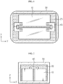
- FIGS. 1 and 2 First, an entire structure of a battery pack according to an embodiment of the present disclosure is described with reference to FIGS. 1 and 2 .
- FIG. 1 is a plan view of an inside of a battery pack according to an embodiment of the present disclosure
- FIG. 2 is a front view of an inside of a battery pack according to an embodiment of the present disclosure.
- the battery pack includes a plurality of battery modules 10, a mold assembly 20, a pack case 30, and a bus bar 40.
- the battery module 10 may be implemented in a form in which a plurality of battery cells are electrically connected and received inside a module case.
- a pouch type-lithium ion battery cell for example, may be used.
- the battery module 10 includes an external terminal electrically connected to battery cells provided therein and exposed to an outside of the module case, and external terminals of adjacent battery modules 10 are connected by the bus bar 40.
- electric connection between the plurality of battery modules 10 may be selectively performed among serial connection, parallel connection, and connection in which serial connection and parallel connection are mixed, in consideration of a voltage, a capacity, etc. required by the battery pack.
- the mold assembly 20, which has received the battery modules 10, is received inside the pack case 30 and may include a polymer resin having excellent impact resistance such as polyethylene (PE), polypropylene (PP), or expanded polypropylene (EPP).
- PE polyethylene
- PP polypropylene
- EPP expanded polypropylene
- the above material is exemplary and the material of the mold assembly 20 according to the present disclosure is not limited thereto, and any material is applicable as long as the material is appropriate for reducing vibration transferred from the outside of the pack case 30.
- FIG. 3 is a view of a mold assembly applied to a battery pack according to an embodiment of the present disclosure
- FIG. 4 is a view of an inner structure of a main mold applied to a battery pack according to an embodiment of the present disclosure
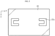
- FIG. 5 is a view of an inner structure of a roof mold applied to a battery pack according to an embodiment of the present disclosure.
- the mold assembly 20 applied to the battery pack includes a main mold 21 configured to provide a space which may accommodate the battery module 10, and a roof mold 22 configured to finish the main mold 21 by covering an upper opening of the main mold 21.
- main mold 21 and the roof mold 22 are individually provided such that the main mold 21 and the roof mold 22 are separable.
- the main mold 21 and the roof mold 22 are coupled to each other by a fastening means P such as a fastening bolt.
- the main mold 21 includes a module receiver 21a as many as the number of the battery modules 10 therein.
- the module receiver 21a has a shape/size corresponding to the battery module 10, and has a size in which the battery module 10 may be forcibly fitted in order to implement an efficient impact alleviation performance through a surface contact between the battery module 10 and an inner surface of the module receiver 21a.
- a contact area between an outer surface of the battery module 10 and an inner surface of the module receiver 21a may be widened maximally. Therefore, an efficient impact reduction effect may be achieved with the battery module 10 not shaken inside the mold assembly 20.
- the roof mold 22 includes a bus bar receiver 22a formed in a surface facing the main mold 21.
- the bus bar receiver 22a is formed as many as the number of bus bars 40 and has a shape/size corresponding to the bus bar 40.
- the bus bar receiver 22a has a size in which the battery module 10 may be forcibly fitted in order to implement an efficient impact alleviation performance through a surface contact between the bus bar 40 and an inner surface of the bus bar receiver 22a.
- a contact area between an outer surface of the battery module 10 and an inner surface of the bus bar receiver 22a may be widened maximally. Therefore, an efficient impact reduction effect may be achieved with the bus bar 40 not shaken inside the mold assembly 20.
- a battery pack according to an embodiment of the present disclosure may include at least one cooling hole formed in the mold assembly 20 in order to suppress a temperature rise due to heating of the battery module 10 while improving an impact resistance as described above.
- the battery pack may include one or more cooling holes also in the pack case 30 in order to completely emit heat, which has been emitted to the outside of the mold assembly 20, to the outside of the battery pack.
Landscapes
- Chemical & Material Sciences (AREA)
- Chemical Kinetics & Catalysis (AREA)
- Electrochemistry (AREA)
- General Chemical & Material Sciences (AREA)
- Battery Mounting, Suspending (AREA)
- Connection Of Batteries Or Terminals (AREA)
Abstract
Description
- The present disclosure relates to a battery pack, and more particularly, to a battery pack having a strong structure against an impact by vibration.
- The present application claims priority to Korean Patent Application No.
10-2016-0125901 filed on September 29, 2016 - In a battery pack for an electric automobile, battery modules including lithium-ion battery cells are fixed on a bottom surface of a battery pack case or fixed to a chassis through bolt fastening. Also, for serial/parallel connection between the plurality of battery modules, the battery pack has a structure in which terminals of each of adjacent battery modules are connected by a bus bar.
- However, this battery pack structure is always exposed to an impact by vibration due to specialty that the battery pack is used for an automobile, and an impact by vibration applied from a chassis to the battery pack causes destruction of parts forming the battery pack.
- Particularly, when an impact by vibration occurs, a fixing state between a bus bar connecting battery modules and a terminal of a battery module is easily loosened due to shaking of the battery modules, which brings about a defective battery pack.
- Furthermore, since an electrode lead or an inner electrode assembly, etc. of each battery cell forming a battery module may be also destroyed when an impact by vibration continues, development of a technology which may reduce an impact by vibration is required.
- The present disclosure is designed to solve the problems of the related art, and therefore the present disclosure is directed to providing a battery pack structure which may remarkably reduce concern of part destruction by vibration without complicating the battery pack structure.
- Technical objects of the present disclosure are not limited to the above object, and these and other objects and advantages of the present disclosure may be understood by those of ordinary skill in the art from the following detailed description.
- In one aspect of the present disclosure, there is provided a battery pack including: a plurality of battery modules mutually connected by a bus bar; a mold assembly including a module receiver configured to receive the battery module; and a pack case configured to receive the mold assembly.
- The battery module may include a plurality of battery cells.
- The bus bar may connect external terminals provided to each of the plurality of battery modules.
- The mold assembly may include: a main mold configured to receive the battery module; and a roof mold configured to cover an upper opening of the main mold.
- The main mold may be fastened to the roof mold by a fastening bolt.
- The module receiver may have a shape corresponding to the battery module.
- The mold assembly may include a polymer resin.
- According to one aspect of the present disclosure, occurrence of a defect of a battery pack may be remarkably reduced by reducing concern of part destruction by vibration while not reducing processability/productivity because a structure of the battery pack is not complicated.
- The accompanying drawings illustrate a preferred embodiment of the present disclosure and together with the foregoing disclosure, serve to provide further understanding of the technical features of the present disclosure, and thus, the present disclosure is not construed as being limited to the drawing.
-
FIG. 1 is a plan view of an inside of a battery pack according to an embodiment of the present disclosure. -
FIG. 2 is a front view of an inside of a battery pack according to an embodiment of the present disclosure. -
FIG. 3 is a view of a mold assembly applied to a battery pack according to an embodiment of the present disclosure. -
FIG. 4 is a view of an inner structure of a main mold applied to a battery pack according to an embodiment of the present disclosure. -
FIG. 5 is a view of an inner structure of a roof mold applied to a battery pack according to an embodiment of the present disclosure. - Hereinafter, preferred embodiments of the present disclosure will be described in detail with reference to the accompanying drawings. Prior to the description, it should be understood that the terms used in the specification and the appended claims should not be construed as limited to general and dictionary meanings, but interpreted based on the meanings and concepts corresponding to technical aspects of the present disclosure on the basis of the principle that the inventor is allowed to define terms appropriately for the best explanation. Therefore, the description proposed herein is just a preferable example for the purpose of illustrations only, not intended to limit the scope of the disclosure, so it should be understood that other equivalents and modifications could be made thereto without departing from the scope of the disclosure.
- First, an entire structure of a battery pack according to an embodiment of the present disclosure is described with reference to
FIGS. 1 and 2 . -
FIG. 1 is a plan view of an inside of a battery pack according to an embodiment of the present disclosure, andFIG. 2 is a front view of an inside of a battery pack according to an embodiment of the present disclosure. - Referring to
FIGS. 1 and 2 , the battery pack according to an embodiment of the present disclosure includes a plurality ofbattery modules 10, amold assembly 20, apack case 30, and abus bar 40. - The
battery module 10 may be implemented in a form in which a plurality of battery cells are electrically connected and received inside a module case. For a battery cell applied to thebattery module 10, a pouch type-lithium ion battery cell, for example, may be used. - The
battery module 10 includes an external terminal electrically connected to battery cells provided therein and exposed to an outside of the module case, and external terminals ofadjacent battery modules 10 are connected by thebus bar 40. - Meanwhile, electric connection between the plurality of
battery modules 10 may be selectively performed among serial connection, parallel connection, and connection in which serial connection and parallel connection are mixed, in consideration of a voltage, a capacity, etc. required by the battery pack. - The
mold assembly 20, which has received thebattery modules 10, is received inside thepack case 30 and may include a polymer resin having excellent impact resistance such as polyethylene (PE), polypropylene (PP), or expanded polypropylene (EPP). - However, the above material is exemplary and the material of the
mold assembly 20 according to the present disclosure is not limited thereto, and any material is applicable as long as the material is appropriate for reducing vibration transferred from the outside of thepack case 30. - A more detailed structure of the
mold assembly 20 is described below with reference toFIGS. 3 to 5 . -
FIG. 3 is a view of a mold assembly applied to a battery pack according to an embodiment of the present disclosure,FIG. 4 is a view of an inner structure of a main mold applied to a battery pack according to an embodiment of the present disclosure, andFIG. 5 is a view of an inner structure of a roof mold applied to a battery pack according to an embodiment of the present disclosure. - First, referring to
FIG. 3 , themold assembly 20 applied to the battery pack according to an embodiment of the present disclosure includes amain mold 21 configured to provide a space which may accommodate thebattery module 10, and aroof mold 22 configured to finish themain mold 21 by covering an upper opening of themain mold 21. - Also, the
main mold 21 and theroof mold 22 are individually provided such that themain mold 21 and theroof mold 22 are separable. Themain mold 21 and theroof mold 22 are coupled to each other by a fastening means P such as a fastening bolt. - Next, the
main mold 21 is described more specifically with reference toFIG. 4 . - Referring to
FIG. 4 , themain mold 21 includes amodule receiver 21a as many as the number of thebattery modules 10 therein. Themodule receiver 21a has a shape/size corresponding to thebattery module 10, and has a size in which thebattery module 10 may be forcibly fitted in order to implement an efficient impact alleviation performance through a surface contact between thebattery module 10 and an inner surface of themodule receiver 21a. - In the case where the
battery module 10 is forcibly fitted inside themodule receiver 21a, a contact area between an outer surface of thebattery module 10 and an inner surface of themodule receiver 21a may be widened maximally. Therefore, an efficient impact reduction effect may be achieved with thebattery module 10 not shaken inside themold assembly 20. - Next, the
roof mold 22 is described more specifically with reference toFIG. 5 . - Referring to
FIG. 5 , theroof mold 22 includes abus bar receiver 22a formed in a surface facing themain mold 21. Thebus bar receiver 22a is formed as many as the number ofbus bars 40 and has a shape/size corresponding to thebus bar 40. Like themodule receiver 21a described above, thebus bar receiver 22a has a size in which thebattery module 10 may be forcibly fitted in order to implement an efficient impact alleviation performance through a surface contact between thebus bar 40 and an inner surface of thebus bar receiver 22a. - In the case where the
bus bar 40 is forcibly fitted inside thebus bar receiver 22a, a contact area between an outer surface of thebattery module 10 and an inner surface of thebus bar receiver 22a may be widened maximally. Therefore, an efficient impact reduction effect may be achieved with thebus bar 40 not shaken inside themold assembly 20. - As described above, in the case where individual movements of the
battery module 10 and thebus bar 40 due to an impact transferred to the battery pack are suppressed, relative movements of thebattery module 10 and thebus bar 40 are also remarkably reduced. Therefore, occurrence of a problem that a fastening portion of thebus bar 40 is destroyed and electrical connection between thebattery modules 10 is cut off may be prevented. - Meanwhile, a battery pack according to an embodiment of the present disclosure may include at least one cooling hole formed in the
mold assembly 20 in order to suppress a temperature rise due to heating of thebattery module 10 while improving an impact resistance as described above. Also, in this case, the battery pack may include one or more cooling holes also in thepack case 30 in order to completely emit heat, which has been emitted to the outside of themold assembly 20, to the outside of the battery pack. - Although the present disclosure has been described with reference to limited embodiments and drawings, the present disclosure is not limited thereto and it will be understood by those of ordinary skill in the art that various changes and modifications in form and details may be made within the scope of the present disclosure and equivalents as defined by the following claims.
Claims (7)
- A battery pack comprising:a plurality of battery modules mutually connected by a bus bar;a mold assembly comprising a module receiver configured to receive the battery module; anda pack case configured to receive the mold assembly.
- The battery pack of claim 1, wherein the battery module comprises a plurality of battery cells.
- The battery pack of claim 1, wherein the bus bar connects external terminals provided to each of the plurality of battery modules.
- The battery pack of claim 1, wherein the mold assembly comprises:a main mold configured to receive the battery module; anda roof mold configured to cover an upper opening of the main mold.
- The battery pack of claim 4, wherein the main mold is fastened to the roof mold by a fastening bolt.
- The battery pack of claim 1, wherein the module receiver has a shape corresponding to the battery module.
- The battery pack of claim 1, wherein the mold assembly comprises a polymer resin.
Applications Claiming Priority (2)
| Application Number | Priority Date | Filing Date | Title |
|---|---|---|---|
| KR1020160125901A KR102115482B1 (en) | 2016-09-29 | 2016-09-29 | Battery pack |
| PCT/KR2017/010339 WO2018062760A1 (en) | 2016-09-29 | 2017-09-20 | Battery pack |
Publications (3)
| Publication Number | Publication Date |
|---|---|
| EP3404737A1 true EP3404737A1 (en) | 2018-11-21 |
| EP3404737A4 EP3404737A4 (en) | 2019-04-17 |
| EP3404737B1 EP3404737B1 (en) | 2025-01-29 |
Family
ID=61760703
Family Applications (1)
| Application Number | Title | Priority Date | Filing Date |
|---|---|---|---|
| EP17856646.9A Active EP3404737B1 (en) | 2016-09-29 | 2017-09-20 | Battery pack |
Country Status (8)
| Country | Link |
|---|---|
| US (1) | US11404738B2 (en) |
| EP (1) | EP3404737B1 (en) |
| JP (1) | JP7039776B2 (en) |
| KR (1) | KR102115482B1 (en) |
| CN (1) | CN208538934U (en) |
| ES (1) | ES3009738T3 (en) |
| HU (1) | HUE070226T2 (en) |
| WO (1) | WO2018062760A1 (en) |
Families Citing this family (3)
| Publication number | Priority date | Publication date | Assignee | Title |
|---|---|---|---|---|
| KR102761658B1 (en) | 2019-07-03 | 2025-01-31 | 주식회사 엘지에너지솔루션 | Battery module, battery pack and energy storage system comprising the same |
| KR102831752B1 (en) * | 2019-10-07 | 2025-07-09 | 주식회사 엘지에너지솔루션 | Battery pack of structure to easily assemble and Method for manufacturing the same |
| JP7338480B2 (en) * | 2020-01-10 | 2023-09-05 | トヨタ自動車株式会社 | Battery cooling structure in vehicle |
Family Cites Families (42)
| Publication number | Priority date | Publication date | Assignee | Title |
|---|---|---|---|---|
| JP3271495B2 (en) * | 1995-10-24 | 2002-04-02 | 松下電器産業株式会社 | Battery pack |
| JP3343889B2 (en) * | 1997-10-13 | 2002-11-11 | トヨタ自動車株式会社 | Connection plate for battery holder |
| US6399238B1 (en) * | 1999-12-13 | 2002-06-04 | Alcatel | Module configuration |
| JP3681051B2 (en) | 1999-12-28 | 2005-08-10 | 本田技研工業株式会社 | Power storage device |
| DE10064648C2 (en) | 1999-12-28 | 2003-09-18 | Honda Motor Co Ltd | battery unit |
| JP4196521B2 (en) * | 2000-05-19 | 2008-12-17 | 新神戸電機株式会社 | Battery structure and battery module for electric vehicle |
| JP2002134078A (en) | 2000-10-26 | 2002-05-10 | Toyota Motor Corp | Collective battery pack |
| JP3575476B2 (en) | 2001-09-17 | 2004-10-13 | 日産自動車株式会社 | Battery pack |
| JP3572404B2 (en) | 2002-03-04 | 2004-10-06 | 日産自動車株式会社 | Battery pack |
| JP3806673B2 (en) | 2002-06-28 | 2006-08-09 | 三洋電機株式会社 | Power supply |
| EP1597782A2 (en) * | 2003-01-17 | 2005-11-23 | Philadelphia Scientific | Ultra safe lead acid battery cell |
| JP4701658B2 (en) * | 2003-10-14 | 2011-06-15 | 日産自動車株式会社 | Battery module and battery pack |
| US7989104B2 (en) | 2004-10-28 | 2011-08-02 | Samsung Sdi Co., Ltd. | Battery module |
| US8026698B2 (en) | 2006-02-09 | 2011-09-27 | Scheucher Karl F | Scalable intelligent power supply system and method |
| KR100911520B1 (en) | 2007-03-08 | 2009-08-10 | 현대자동차주식회사 | Battery module storage |
| JP4477048B2 (en) * | 2007-08-23 | 2010-06-09 | 矢崎総業株式会社 | Power supply |
| JP5155772B2 (en) * | 2008-08-19 | 2013-03-06 | 三菱重工業株式会社 | Battery pack structure |
| JP5284053B2 (en) * | 2008-11-17 | 2013-09-11 | 株式会社東芝 | Secondary battery pack |
| JP4935802B2 (en) * | 2008-12-10 | 2012-05-23 | パナソニック株式会社 | Battery module and assembled battery module using the same |
| JP4900534B2 (en) * | 2009-02-24 | 2012-03-21 | パナソニック株式会社 | Battery module and battery module assembly using the same |
| WO2010135456A2 (en) * | 2009-05-20 | 2010-11-25 | Johnson Controls - Saft Advanced Power Solutions Llc | Lithium ion battery module |
| JP5509684B2 (en) | 2009-06-03 | 2014-06-04 | ソニー株式会社 | Battery pack |
| JP5537111B2 (en) | 2009-09-30 | 2014-07-02 | 株式会社東芝 | Secondary battery device |
| KR101146492B1 (en) * | 2010-07-01 | 2012-05-21 | 에스비리모티브 주식회사 | Battery Pack |
| JP5542558B2 (en) | 2010-07-15 | 2014-07-09 | 株式会社東芝 | Secondary battery device |
| JP5699536B2 (en) | 2010-10-26 | 2015-04-15 | ソニー株式会社 | Battery unit |
| JP6012595B2 (en) | 2011-03-29 | 2016-10-25 | 三洋電機株式会社 | Battery module, battery system, electric vehicle, moving object, power storage device, power supply device, and electric device |
| US9472797B2 (en) * | 2011-05-25 | 2016-10-18 | Samsung Sdi Co., Ltd. | Battery pack |
| KR20130062197A (en) * | 2011-12-02 | 2013-06-12 | 삼성에스디아이 주식회사 | Battery pack and method of manufacturing thereof |
| JP5925290B2 (en) | 2012-02-29 | 2016-05-25 | 住友重機械工業株式会社 | Excavator |
| JP6049276B2 (en) | 2012-03-14 | 2016-12-21 | 株式会社東芝 | Secondary battery device |
| KR20140064487A (en) * | 2012-11-20 | 2014-05-28 | 삼성에스디아이 주식회사 | Rechargeable battery module |
| US9799872B2 (en) * | 2013-01-18 | 2017-10-24 | Samsung Sdi Co., Ltd. | Battery module |
| JP6243624B2 (en) * | 2013-05-07 | 2017-12-06 | 矢崎総業株式会社 | Bus bar module and power supply |
| CN105229821A (en) * | 2013-05-21 | 2016-01-06 | 矢崎总业株式会社 | Battery connecting structure and electric supply installation |
| KR101709562B1 (en) * | 2013-07-31 | 2017-03-08 | 주식회사 엘지화학 | Battery Module Assembly |
| KR102272264B1 (en) * | 2014-01-20 | 2021-07-02 | 삼성에스디아이 주식회사 | Battery module having short connecting part |
| KR102233776B1 (en) * | 2014-01-28 | 2021-03-30 | 삼성에스디아이 주식회사 | Battery module |
| JP6252313B2 (en) | 2014-03-31 | 2017-12-27 | 株式会社Gsユアサ | Power storage device |
| JP6355956B2 (en) | 2014-04-16 | 2018-07-11 | 矢崎エナジーシステム株式会社 | Battery pack and power supply |
| JP6260467B2 (en) | 2014-06-24 | 2018-01-17 | 株式会社Gsユアサ | Assembled battery |
| JP6606818B2 (en) | 2014-10-17 | 2019-11-20 | 住友電気工業株式会社 | Power storage device module |
-
2016
- 2016-09-29 KR KR1020160125901A patent/KR102115482B1/en active Active
-
2017
- 2017-09-20 ES ES17856646T patent/ES3009738T3/en active Active
- 2017-09-20 HU HUE17856646A patent/HUE070226T2/en unknown
- 2017-09-20 US US16/072,400 patent/US11404738B2/en active Active
- 2017-09-20 WO PCT/KR2017/010339 patent/WO2018062760A1/en not_active Ceased
- 2017-09-20 CN CN201790000599.6U patent/CN208538934U/en active Active
- 2017-09-20 JP JP2018539293A patent/JP7039776B2/en active Active
- 2017-09-20 EP EP17856646.9A patent/EP3404737B1/en active Active
Also Published As
| Publication number | Publication date |
|---|---|
| JP7039776B2 (en) | 2022-03-23 |
| ES3009738T3 (en) | 2025-03-31 |
| CN208538934U (en) | 2019-02-22 |
| KR102115482B1 (en) | 2020-05-26 |
| EP3404737A4 (en) | 2019-04-17 |
| JP2019507472A (en) | 2019-03-14 |
| US11404738B2 (en) | 2022-08-02 |
| EP3404737B1 (en) | 2025-01-29 |
| KR20180035598A (en) | 2018-04-06 |
| WO2018062760A1 (en) | 2018-04-05 |
| US20190027721A1 (en) | 2019-01-24 |
| HUE070226T2 (en) | 2025-05-28 |
Similar Documents
| Publication | Publication Date | Title |
|---|---|---|
| US11673205B2 (en) | Battery module having bus bar, and battery pack | |
| EP3540817B1 (en) | Battery pack | |
| EP3151306B1 (en) | Rechargeable battery | |
| US10355255B2 (en) | Battery module and battery pack comprising same | |
| EP4053989B1 (en) | Battery module having busbar, battery pack and vehicle | |
| KR20190118017A (en) | Battery Pack Having Pack Housing | |
| US10361410B2 (en) | Battery pack | |
| US20130052503A1 (en) | Battery system and method for coupling a battery cell assembly to an electrically non-conductive base member | |
| US20160211499A1 (en) | Battery module | |
| US20180233720A1 (en) | Electrical box for battery pack and battery pack structure using same | |
| US12362435B2 (en) | Battery module comprising module bus bar, battery pack comprising same, and electronic device | |
| US10446869B2 (en) | Battery module, battery pack including same, and method for manufacturing casing for battery module | |
| US20160149167A1 (en) | Rechargeable battery | |
| EP3404737B1 (en) | Battery pack | |
| KR20160015751A (en) | Structure for fixing dimension of battery cell and parallel connecting structure between battery cells using the same | |
| EP3285312A1 (en) | Battery module and battery pack comprising same | |
| US9123950B2 (en) | Battery module and battery cell | |
| JP2009129722A (en) | Lithium-ion secondary battery | |
| EP2830121B1 (en) | Rechargeable battery | |
| KR102647222B1 (en) | Terminal cover and battery pack having the same | |
| EP3032614A1 (en) | Battery module and battery cell | |
| US10593924B2 (en) | Cell contact-making system, cell module and method for producing a cell module | |
| KR102289582B1 (en) | Battery housing with sealed structure and Method for manufacturing battery module using the same | |
| EP4693346A1 (en) | Resistor unit, resistor assembly, and battery pack |
Legal Events
| Date | Code | Title | Description |
|---|---|---|---|
| STAA | Information on the status of an ep patent application or granted ep patent |
Free format text: STATUS: THE INTERNATIONAL PUBLICATION HAS BEEN MADE |
|
| PUAI | Public reference made under article 153(3) epc to a published international application that has entered the european phase |
Free format text: ORIGINAL CODE: 0009012 |
|
| STAA | Information on the status of an ep patent application or granted ep patent |
Free format text: STATUS: REQUEST FOR EXAMINATION WAS MADE |
|
| 17P | Request for examination filed |
Effective date: 20180817 |
|
| AK | Designated contracting states |
Kind code of ref document: A1 Designated state(s): AL AT BE BG CH CY CZ DE DK EE ES FI FR GB GR HR HU IE IS IT LI LT LU LV MC MK MT NL NO PL PT RO RS SE SI SK SM TR |
|
| AX | Request for extension of the european patent |
Extension state: BA ME |
|
| A4 | Supplementary search report drawn up and despatched |
Effective date: 20190314 |
|
| RIC1 | Information provided on ipc code assigned before grant |
Ipc: H01M 2/10 20060101AFI20190308BHEP Ipc: H01M 2/20 20060101ALN20190308BHEP |
|
| DAV | Request for validation of the european patent (deleted) | ||
| DAX | Request for extension of the european patent (deleted) | ||
| RAP1 | Party data changed (applicant data changed or rights of an application transferred) |
Owner name: LG ENERGY SOLUTION LTD. |
|
| RAP3 | Party data changed (applicant data changed or rights of an application transferred) |
Owner name: LG ENERGY SOLUTION, LTD. |
|
| REG | Reference to a national code |
Ref country code: DE Ref legal event code: R079 Free format text: PREVIOUS MAIN CLASS: H01M0002100000 Ipc: H01M0050211000 Ref country code: DE Ref legal event code: R079 Ref document number: 602017087587 Country of ref document: DE Free format text: PREVIOUS MAIN CLASS: H01M0002100000 Ipc: H01M0050211000 |
|
| GRAP | Despatch of communication of intention to grant a patent |
Free format text: ORIGINAL CODE: EPIDOSNIGR1 |
|
| STAA | Information on the status of an ep patent application or granted ep patent |
Free format text: STATUS: GRANT OF PATENT IS INTENDED |
|
| GRAJ | Information related to disapproval of communication of intention to grant by the applicant or resumption of examination proceedings by the epo deleted |
Free format text: ORIGINAL CODE: EPIDOSDIGR1 |
|
| STAA | Information on the status of an ep patent application or granted ep patent |
Free format text: STATUS: REQUEST FOR EXAMINATION WAS MADE |
|
| GRAP | Despatch of communication of intention to grant a patent |
Free format text: ORIGINAL CODE: EPIDOSNIGR1 |
|
| STAA | Information on the status of an ep patent application or granted ep patent |
Free format text: STATUS: GRANT OF PATENT IS INTENDED |
|
| RIC1 | Information provided on ipc code assigned before grant |
Ipc: H01M 50/50 20210101ALI20240917BHEP Ipc: H01M 50/271 20210101ALI20240917BHEP Ipc: H01M 50/262 20210101ALI20240917BHEP Ipc: H01M 50/242 20210101ALI20240917BHEP Ipc: H01M 50/24 20210101ALI20240917BHEP Ipc: H01M 50/227 20210101ALI20240917BHEP Ipc: H01M 50/211 20210101AFI20240917BHEP |
|
| INTG | Intention to grant announced |
Effective date: 20240927 |
|
| INTC | Intention to grant announced (deleted) | ||
| INTG | Intention to grant announced |
Effective date: 20241018 |
|
| P01 | Opt-out of the competence of the unified patent court (upc) registered |
Free format text: CASE NUMBER: APP_56668/2024 Effective date: 20241017 |
|
| GRAS | Grant fee paid |
Free format text: ORIGINAL CODE: EPIDOSNIGR3 |
|
| GRAA | (expected) grant |
Free format text: ORIGINAL CODE: 0009210 |
|
| STAA | Information on the status of an ep patent application or granted ep patent |
Free format text: STATUS: THE PATENT HAS BEEN GRANTED |
|
| AK | Designated contracting states |
Kind code of ref document: B1 Designated state(s): AL AT BE BG CH CY CZ DE DK EE ES FI FR GB GR HR HU IE IS IT LI LT LU LV MC MK MT NL NO PL PT RO RS SE SI SK SM TR |
|
| REG | Reference to a national code |
Ref country code: GB Ref legal event code: FG4D |
|
| REG | Reference to a national code |
Ref country code: CH Ref legal event code: EP |
|
| REG | Reference to a national code |
Ref country code: DE Ref legal event code: R096 Ref document number: 602017087587 Country of ref document: DE |
|
| REG | Reference to a national code |
Ref country code: IE Ref legal event code: FG4D |
|
| REG | Reference to a national code |
Ref country code: ES Ref legal event code: FG2A Ref document number: 3009738 Country of ref document: ES Kind code of ref document: T3 Effective date: 20250331 |
|
| REG | Reference to a national code |
Ref country code: HU Ref legal event code: AG4A Ref document number: E070226 Country of ref document: HU |
|
| REG | Reference to a national code |
Ref country code: NL Ref legal event code: MP Effective date: 20250129 |
|
| PG25 | Lapsed in a contracting state [announced via postgrant information from national office to epo] |
Ref country code: NL Free format text: LAPSE BECAUSE OF FAILURE TO SUBMIT A TRANSLATION OF THE DESCRIPTION OR TO PAY THE FEE WITHIN THE PRESCRIBED TIME-LIMIT Effective date: 20250129 |
|
| PG25 | Lapsed in a contracting state [announced via postgrant information from national office to epo] |
Ref country code: RS Free format text: LAPSE BECAUSE OF FAILURE TO SUBMIT A TRANSLATION OF THE DESCRIPTION OR TO PAY THE FEE WITHIN THE PRESCRIBED TIME-LIMIT Effective date: 20250429 |
|
| PG25 | Lapsed in a contracting state [announced via postgrant information from national office to epo] |
Ref country code: FI Free format text: LAPSE BECAUSE OF FAILURE TO SUBMIT A TRANSLATION OF THE DESCRIPTION OR TO PAY THE FEE WITHIN THE PRESCRIBED TIME-LIMIT Effective date: 20250129 |
|
| PG25 | Lapsed in a contracting state [announced via postgrant information from national office to epo] |
Ref country code: PL Free format text: LAPSE BECAUSE OF FAILURE TO SUBMIT A TRANSLATION OF THE DESCRIPTION OR TO PAY THE FEE WITHIN THE PRESCRIBED TIME-LIMIT Effective date: 20250129 |
|
| REG | Reference to a national code |
Ref country code: LT Ref legal event code: MG9D |
|
| PG25 | Lapsed in a contracting state [announced via postgrant information from national office to epo] |
Ref country code: NO Free format text: LAPSE BECAUSE OF FAILURE TO SUBMIT A TRANSLATION OF THE DESCRIPTION OR TO PAY THE FEE WITHIN THE PRESCRIBED TIME-LIMIT Effective date: 20250429 Ref country code: IS Free format text: LAPSE BECAUSE OF FAILURE TO SUBMIT A TRANSLATION OF THE DESCRIPTION OR TO PAY THE FEE WITHIN THE PRESCRIBED TIME-LIMIT Effective date: 20250529 |
|
| REG | Reference to a national code |
Ref country code: AT Ref legal event code: MK05 Ref document number: 1764411 Country of ref document: AT Kind code of ref document: T Effective date: 20250129 |
|
| PG25 | Lapsed in a contracting state [announced via postgrant information from national office to epo] |
Ref country code: HR Free format text: LAPSE BECAUSE OF FAILURE TO SUBMIT A TRANSLATION OF THE DESCRIPTION OR TO PAY THE FEE WITHIN THE PRESCRIBED TIME-LIMIT Effective date: 20250129 |
|
| PG25 | Lapsed in a contracting state [announced via postgrant information from national office to epo] |
Ref country code: LV Free format text: LAPSE BECAUSE OF FAILURE TO SUBMIT A TRANSLATION OF THE DESCRIPTION OR TO PAY THE FEE WITHIN THE PRESCRIBED TIME-LIMIT Effective date: 20250129 Ref country code: PT Free format text: LAPSE BECAUSE OF FAILURE TO SUBMIT A TRANSLATION OF THE DESCRIPTION OR TO PAY THE FEE WITHIN THE PRESCRIBED TIME-LIMIT Effective date: 20250529 |
|
| PG25 | Lapsed in a contracting state [announced via postgrant information from national office to epo] |
Ref country code: BG Free format text: LAPSE BECAUSE OF FAILURE TO SUBMIT A TRANSLATION OF THE DESCRIPTION OR TO PAY THE FEE WITHIN THE PRESCRIBED TIME-LIMIT Effective date: 20250129 Ref country code: GR Free format text: LAPSE BECAUSE OF FAILURE TO SUBMIT A TRANSLATION OF THE DESCRIPTION OR TO PAY THE FEE WITHIN THE PRESCRIBED TIME-LIMIT Effective date: 20250430 |
|
| PG25 | Lapsed in a contracting state [announced via postgrant information from national office to epo] |
Ref country code: AT Free format text: LAPSE BECAUSE OF FAILURE TO SUBMIT A TRANSLATION OF THE DESCRIPTION OR TO PAY THE FEE WITHIN THE PRESCRIBED TIME-LIMIT Effective date: 20250129 |
|
| PG25 | Lapsed in a contracting state [announced via postgrant information from national office to epo] |
Ref country code: SE Free format text: LAPSE BECAUSE OF FAILURE TO SUBMIT A TRANSLATION OF THE DESCRIPTION OR TO PAY THE FEE WITHIN THE PRESCRIBED TIME-LIMIT Effective date: 20250129 |
|
| PG25 | Lapsed in a contracting state [announced via postgrant information from national office to epo] |
Ref country code: SM Free format text: LAPSE BECAUSE OF FAILURE TO SUBMIT A TRANSLATION OF THE DESCRIPTION OR TO PAY THE FEE WITHIN THE PRESCRIBED TIME-LIMIT Effective date: 20250129 |
|
| PG25 | Lapsed in a contracting state [announced via postgrant information from national office to epo] |
Ref country code: DK Free format text: LAPSE BECAUSE OF FAILURE TO SUBMIT A TRANSLATION OF THE DESCRIPTION OR TO PAY THE FEE WITHIN THE PRESCRIBED TIME-LIMIT Effective date: 20250129 |
|
| PGFP | Annual fee paid to national office [announced via postgrant information from national office to epo] |
Ref country code: DE Payment date: 20250820 Year of fee payment: 9 |
|
| PG25 | Lapsed in a contracting state [announced via postgrant information from national office to epo] |
Ref country code: IT Free format text: LAPSE BECAUSE OF FAILURE TO SUBMIT A TRANSLATION OF THE DESCRIPTION OR TO PAY THE FEE WITHIN THE PRESCRIBED TIME-LIMIT Effective date: 20250129 |
|
| PGFP | Annual fee paid to national office [announced via postgrant information from national office to epo] |
Ref country code: HU Payment date: 20250929 Year of fee payment: 9 Ref country code: GB Payment date: 20250820 Year of fee payment: 9 Ref country code: BE Payment date: 20250820 Year of fee payment: 9 |
|
| PGFP | Annual fee paid to national office [announced via postgrant information from national office to epo] |
Ref country code: FR Payment date: 20250821 Year of fee payment: 9 |
|
| PG25 | Lapsed in a contracting state [announced via postgrant information from national office to epo] |
Ref country code: EE Free format text: LAPSE BECAUSE OF FAILURE TO SUBMIT A TRANSLATION OF THE DESCRIPTION OR TO PAY THE FEE WITHIN THE PRESCRIBED TIME-LIMIT Effective date: 20250129 Ref country code: CZ Free format text: LAPSE BECAUSE OF FAILURE TO SUBMIT A TRANSLATION OF THE DESCRIPTION OR TO PAY THE FEE WITHIN THE PRESCRIBED TIME-LIMIT Effective date: 20250129 |
|
| PG25 | Lapsed in a contracting state [announced via postgrant information from national office to epo] |
Ref country code: RO Free format text: LAPSE BECAUSE OF FAILURE TO SUBMIT A TRANSLATION OF THE DESCRIPTION OR TO PAY THE FEE WITHIN THE PRESCRIBED TIME-LIMIT Effective date: 20250129 |
|
| PG25 | Lapsed in a contracting state [announced via postgrant information from national office to epo] |
Ref country code: SK Free format text: LAPSE BECAUSE OF FAILURE TO SUBMIT A TRANSLATION OF THE DESCRIPTION OR TO PAY THE FEE WITHIN THE PRESCRIBED TIME-LIMIT Effective date: 20250129 |
|
| REG | Reference to a national code |
Ref country code: DE Ref legal event code: R097 Ref document number: 602017087587 Country of ref document: DE |
|
| PLBE | No opposition filed within time limit |
Free format text: ORIGINAL CODE: 0009261 |
|
| STAA | Information on the status of an ep patent application or granted ep patent |
Free format text: STATUS: NO OPPOSITION FILED WITHIN TIME LIMIT |
|
| REG | Reference to a national code |
Ref country code: CH Ref legal event code: L10 Free format text: ST27 STATUS EVENT CODE: U-0-0-L10-L00 (AS PROVIDED BY THE NATIONAL OFFICE) Effective date: 20251210 |
|
| 26N | No opposition filed |
Effective date: 20251030 |
|
| PGFP | Annual fee paid to national office [announced via postgrant information from national office to epo] |
Ref country code: ES Payment date: 20251007 Year of fee payment: 9 |
|
| REG | Reference to a national code |
Ref country code: CH Ref legal event code: H13 Free format text: ST27 STATUS EVENT CODE: U-0-0-H10-H13 (AS PROVIDED BY THE NATIONAL OFFICE) Effective date: 20260504 |