EP3404515A1 - Electronic system and proximity sensing method - Google Patents
Electronic system and proximity sensing method Download PDFInfo
- Publication number
- EP3404515A1 EP3404515A1 EP18172029.3A EP18172029A EP3404515A1 EP 3404515 A1 EP3404515 A1 EP 3404515A1 EP 18172029 A EP18172029 A EP 18172029A EP 3404515 A1 EP3404515 A1 EP 3404515A1
- Authority
- EP
- European Patent Office
- Prior art keywords
- proximity
- values
- sensors
- proximity values
- physical
- Prior art date
- Legal status (The legal status is an assumption and is not a legal conclusion. Google has not performed a legal analysis and makes no representation as to the accuracy of the status listed.)
- Granted
Links
Images





Classifications
-
- G—PHYSICS
- G06—COMPUTING OR CALCULATING; COUNTING
- G06F—ELECTRIC DIGITAL DATA PROCESSING
- G06F3/00—Input arrangements for transferring data to be processed into a form capable of being handled by the computer; Output arrangements for transferring data from processing unit to output unit, e.g. interface arrangements
- G06F3/01—Input arrangements or combined input and output arrangements for interaction between user and computer
- G06F3/03—Arrangements for converting the position or the displacement of a member into a coded form
- G06F3/033—Pointing devices displaced or positioned by the user, e.g. mice, trackballs, pens or joysticks; Accessories therefor
- G06F3/038—Control and interface arrangements therefor, e.g. drivers or device-embedded control circuitry
-
- G—PHYSICS
- G06—COMPUTING OR CALCULATING; COUNTING
- G06F—ELECTRIC DIGITAL DATA PROCESSING
- G06F3/00—Input arrangements for transferring data to be processed into a form capable of being handled by the computer; Output arrangements for transferring data from processing unit to output unit, e.g. interface arrangements
- G06F3/01—Input arrangements or combined input and output arrangements for interaction between user and computer
- G06F3/03—Arrangements for converting the position or the displacement of a member into a coded form
- G06F3/041—Digitisers, e.g. for touch screens or touch pads, characterised by the transducing means
-
- A—HUMAN NECESSITIES
- A63—SPORTS; GAMES; AMUSEMENTS
- A63F—CARD, BOARD, OR ROULETTE GAMES; INDOOR GAMES USING SMALL MOVING PLAYING BODIES; VIDEO GAMES; GAMES NOT OTHERWISE PROVIDED FOR
- A63F13/00—Video games, i.e. games using an electronically generated display having two or more dimensions
- A63F13/20—Input arrangements for video game devices
- A63F13/21—Input arrangements for video game devices characterised by their sensors, purposes or types
- A63F13/214—Input arrangements for video game devices characterised by their sensors, purposes or types for locating contacts on a surface, e.g. floor mats or touch pads
-
- A—HUMAN NECESSITIES
- A63—SPORTS; GAMES; AMUSEMENTS
- A63F—CARD, BOARD, OR ROULETTE GAMES; INDOOR GAMES USING SMALL MOVING PLAYING BODIES; VIDEO GAMES; GAMES NOT OTHERWISE PROVIDED FOR
- A63F13/00—Video games, i.e. games using an electronically generated display having two or more dimensions
- A63F13/20—Input arrangements for video game devices
- A63F13/22—Setup operations, e.g. calibration, key configuration or button assignment
-
- A—HUMAN NECESSITIES
- A63—SPORTS; GAMES; AMUSEMENTS
- A63F—CARD, BOARD, OR ROULETTE GAMES; INDOOR GAMES USING SMALL MOVING PLAYING BODIES; VIDEO GAMES; GAMES NOT OTHERWISE PROVIDED FOR
- A63F13/00—Video games, i.e. games using an electronically generated display having two or more dimensions
- A63F13/20—Input arrangements for video game devices
- A63F13/24—Constructional details thereof, e.g. game controllers with detachable joystick handles
-
- G—PHYSICS
- G01—MEASURING; TESTING
- G01B—MEASURING LENGTH, THICKNESS OR SIMILAR LINEAR DIMENSIONS; MEASURING ANGLES; MEASURING AREAS; MEASURING IRREGULARITIES OF SURFACES OR CONTOURS
- G01B11/00—Measuring arrangements characterised by the use of optical techniques
- G01B11/14—Measuring arrangements characterised by the use of optical techniques for measuring distance or clearance between spaced objects or spaced apertures
-
- G—PHYSICS
- G01—MEASURING; TESTING
- G01K—MEASURING TEMPERATURE; MEASURING QUANTITY OF HEAT; THERMALLY-SENSITIVE ELEMENTS NOT OTHERWISE PROVIDED FOR
- G01K3/00—Thermometers giving results other than momentary value of temperature
- G01K3/02—Thermometers giving results other than momentary value of temperature giving means values; giving integrated values
- G01K3/06—Thermometers giving results other than momentary value of temperature giving means values; giving integrated values in respect of space
-
- G—PHYSICS
- G01—MEASURING; TESTING
- G01L—MEASURING FORCE, STRESS, TORQUE, WORK, MECHANICAL POWER, MECHANICAL EFFICIENCY, OR FLUID PRESSURE
- G01L1/00—Measuring force or stress, in general
-
- G—PHYSICS
- G01—MEASURING; TESTING
- G01S—RADIO DIRECTION-FINDING; RADIO NAVIGATION; DETERMINING DISTANCE OR VELOCITY BY USE OF RADIO WAVES; LOCATING OR PRESENCE-DETECTING BY USE OF THE REFLECTION OR RERADIATION OF RADIO WAVES; ANALOGOUS ARRANGEMENTS USING OTHER WAVES
- G01S17/00—Systems using the reflection or reradiation of electromagnetic waves other than radio waves, e.g. lidar systems
- G01S17/02—Systems using the reflection of electromagnetic waves other than radio waves
- G01S17/06—Systems determining position data of a target
- G01S17/08—Systems determining position data of a target for measuring distance only
-
- G—PHYSICS
- G06—COMPUTING OR CALCULATING; COUNTING
- G06F—ELECTRIC DIGITAL DATA PROCESSING
- G06F3/00—Input arrangements for transferring data to be processed into a form capable of being handled by the computer; Output arrangements for transferring data from processing unit to output unit, e.g. interface arrangements
- G06F3/01—Input arrangements or combined input and output arrangements for interaction between user and computer
- G06F3/03—Arrangements for converting the position or the displacement of a member into a coded form
- G06F3/033—Pointing devices displaced or positioned by the user, e.g. mice, trackballs, pens or joysticks; Accessories therefor
- G06F3/0354—Pointing devices displaced or positioned by the user, e.g. mice, trackballs, pens or joysticks; Accessories therefor with detection of two-dimensional [2D] relative movements between the device, or an operating part thereof, and a plane or surface, e.g. 2D mice, trackballs, pens or pucks
- G06F3/03547—Touch pads, in which fingers can move on a surface
-
- G—PHYSICS
- G06—COMPUTING OR CALCULATING; COUNTING
- G06F—ELECTRIC DIGITAL DATA PROCESSING
- G06F3/00—Input arrangements for transferring data to be processed into a form capable of being handled by the computer; Output arrangements for transferring data from processing unit to output unit, e.g. interface arrangements
- G06F3/01—Input arrangements or combined input and output arrangements for interaction between user and computer
- G06F3/048—Interaction techniques based on graphical user interfaces [GUI]
- G06F3/0487—Interaction techniques based on graphical user interfaces [GUI] using specific features provided by the input device, e.g. functions controlled by the rotation of a mouse with dual sensing arrangements, or of the nature of the input device, e.g. tap gestures based on pressure sensed by a digitiser
- G06F3/0488—Interaction techniques based on graphical user interfaces [GUI] using specific features provided by the input device, e.g. functions controlled by the rotation of a mouse with dual sensing arrangements, or of the nature of the input device, e.g. tap gestures based on pressure sensed by a digitiser using a touch-screen or digitiser, e.g. input of commands through traced gestures
- G06F3/04883—Interaction techniques based on graphical user interfaces [GUI] using specific features provided by the input device, e.g. functions controlled by the rotation of a mouse with dual sensing arrangements, or of the nature of the input device, e.g. tap gestures based on pressure sensed by a digitiser using a touch-screen or digitiser, e.g. input of commands through traced gestures for inputting data by handwriting, e.g. gesture or text
-
- H—ELECTRICITY
- H03—ELECTRONIC CIRCUITRY
- H03K—PULSE TECHNIQUE
- H03K17/00—Electronic switching or gating, i.e. not by contact-making and –breaking
- H03K17/94—Electronic switching or gating, i.e. not by contact-making and –breaking characterised by the way in which the control signals are generated
- H03K17/945—Proximity switches
- H03K17/955—Proximity switches using a capacitive detector
-
- H—ELECTRICITY
- H03—ELECTRONIC CIRCUITRY
- H03K—PULSE TECHNIQUE
- H03K17/00—Electronic switching or gating, i.e. not by contact-making and –breaking
- H03K17/94—Electronic switching or gating, i.e. not by contact-making and –breaking characterised by the way in which the control signals are generated
- H03K17/96—Touch switches
- H03K17/962—Capacitive touch switches
-
- G—PHYSICS
- G06—COMPUTING OR CALCULATING; COUNTING
- G06F—ELECTRIC DIGITAL DATA PROCESSING
- G06F2203/00—Indexing scheme relating to G06F3/00 - G06F3/048
- G06F2203/038—Indexing scheme relating to G06F3/038
- G06F2203/0383—Remote input, i.e. interface arrangements in which the signals generated by a pointing device are transmitted to a PC at a remote location, e.g. to a PC in a LAN
-
- G—PHYSICS
- G06—COMPUTING OR CALCULATING; COUNTING
- G06F—ELECTRIC DIGITAL DATA PROCESSING
- G06F3/00—Input arrangements for transferring data to be processed into a form capable of being handled by the computer; Output arrangements for transferring data from processing unit to output unit, e.g. interface arrangements
- G06F3/01—Input arrangements or combined input and output arrangements for interaction between user and computer
- G06F3/03—Arrangements for converting the position or the displacement of a member into a coded form
- G06F3/033—Pointing devices displaced or positioned by the user, e.g. mice, trackballs, pens or joysticks; Accessories therefor
- G06F3/0346—Pointing devices displaced or positioned by the user, e.g. mice, trackballs, pens or joysticks; Accessories therefor with detection of the device orientation or free movement in a three-dimensional [3D] space, e.g. 3D mice, 6-DOF [six degrees of freedom] pointers using gyroscopes, accelerometers or tilt-sensors
-
- G—PHYSICS
- G06—COMPUTING OR CALCULATING; COUNTING
- G06F—ELECTRIC DIGITAL DATA PROCESSING
- G06F3/00—Input arrangements for transferring data to be processed into a form capable of being handled by the computer; Output arrangements for transferring data from processing unit to output unit, e.g. interface arrangements
- G06F3/01—Input arrangements or combined input and output arrangements for interaction between user and computer
- G06F3/03—Arrangements for converting the position or the displacement of a member into a coded form
- G06F3/041—Digitisers, e.g. for touch screens or touch pads, characterised by the transducing means
- G06F3/0416—Control or interface arrangements specially adapted for digitisers
-
- H—ELECTRICITY
- H03—ELECTRONIC CIRCUITRY
- H03K—PULSE TECHNIQUE
- H03K17/00—Electronic switching or gating, i.e. not by contact-making and –breaking
- H03K17/94—Electronic switching or gating, i.e. not by contact-making and –breaking characterised by the way in which the control signals are generated
- H03K17/945—Proximity switches
-
- H—ELECTRICITY
- H03—ELECTRONIC CIRCUITRY
- H03K—PULSE TECHNIQUE
- H03K17/00—Electronic switching or gating, i.e. not by contact-making and –breaking
- H03K17/94—Electronic switching or gating, i.e. not by contact-making and –breaking characterised by the way in which the control signals are generated
- H03K17/96—Touch switches
-
- H—ELECTRICITY
- H03—ELECTRONIC CIRCUITRY
- H03K—PULSE TECHNIQUE
- H03K2217/00—Indexing scheme related to electronic switching or gating, i.e. not by contact-making or -breaking covered by H03K17/00
- H03K2217/94—Indexing scheme related to electronic switching or gating, i.e. not by contact-making or -breaking covered by H03K17/00 characterised by the way in which the control signal is generated
- H03K2217/9401—Calibration techniques
- H03K2217/94026—Automatic threshold calibration; e.g. threshold automatically adapts to ambient conditions or follows variation of input
-
- H—ELECTRICITY
- H03—ELECTRONIC CIRCUITRY
- H03K—PULSE TECHNIQUE
- H03K2217/00—Indexing scheme related to electronic switching or gating, i.e. not by contact-making or -breaking covered by H03K17/00
- H03K2217/94—Indexing scheme related to electronic switching or gating, i.e. not by contact-making or -breaking covered by H03K17/00 characterised by the way in which the control signal is generated
- H03K2217/94036—Multiple detection, i.e. where different switching signals are generated after operation of the user is detected at different time instants at different locations during the actuation movement by two or more sensors of the same or different kinds
-
- H—ELECTRICITY
- H03—ELECTRONIC CIRCUITRY
- H03K—PULSE TECHNIQUE
- H03K2217/00—Indexing scheme related to electronic switching or gating, i.e. not by contact-making or -breaking covered by H03K17/00
- H03K2217/94—Indexing scheme related to electronic switching or gating, i.e. not by contact-making or -breaking covered by H03K17/00 characterised by the way in which the control signal is generated
- H03K2217/96—Touch switches
- H03K2217/96035—Touch switches by temperature detection, i.e. body heat
Definitions
- Present disclosure relates to a system and a method for proximity detection. More particularly, the present disclosure relates to a system and a method for calibrating or updating a threshold value of proximity detection.
- Proximity detection is a technology to detect a distance from a proximity sensor to a target object.
- the proximity sensor may generate a proximity value which reflects the distance. When the proximity value exceeds a threshold, the proximity sensor detects that the target object is near. On the other hand, when the proximity value is below a threshold, the proximity sensor detects that the target object is far.
- Proximity detection is useful in various applications.
- the proximity sensor can be disposed on a mobile phone to detect whether the user is adjacent to the phone.
- the disclosure provides an electronic system, which includes a hand-held controller and a computing application.
- the hand-held controller includes a proximity sensing circuit and a physical information sensing circuit.
- the proximity sensing circuit includes proximity sensors.
- the proximity sensors are configured to sense instant proximity values.
- the physical information sensing circuit is configured to sense a physical parameter.
- the computing application is executed by a processor.
- the computing application is configured to retrieve the instant proximity values and the physical parameter, to calculate maximum proximity values or minimum proximity values according to the instant proximity values and the physical parameter.
- the maximum proximity values or the minimum proximity values are utilized to update threshold proximity values of the proximity sensors in determining near status or far status.
- Another aspect of present disclosure is to provide a proximity sensing method, which include following steps. Instant proximity values are sensed by proximity sensors disposed on a hand-held controller. A physical parameter is sensed by a physical information sensing circuit disposed on the hand-held controller. Maximum proximity values or minimum proximity values are calculated according to the instant proximity values and the physical parameter. The maximum proximity values or the minimum proximity values are utilized to update threshold proximity values of the proximity sensors in determining near status or far status.
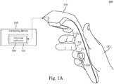
- Fig. 1A is a schematic diagram illustrating an electronic system 100 according to some embodiments of the present disclosure.
- Fig. 1B is another schematic diagram illustrating the electronic system 100 in Fig. 1A .
- the electronic system 100 includes a hand-held controller 120 and a computing application 140.
- the computing application 140 is executed by a processor 162 of a computing device 160.
- the computing device 160 is communicatively connected through a wireless connection (e.g., WiFi, Bluetooth, BLE or IR) or a wired connection (e.g., via a cable wiring) to the hand-held controller 120.
- a wireless connection e.g., WiFi, Bluetooth, BLE or IR
- a wired connection e.g., via a cable wiring
- the computing device 160 can be a computer, a game console, a server or any equivalent device with computation ability.
- the processor 162 may be a CPU, GPU, ASIC or some control unit of the computing device 160, and the computing application 140 may be software or firmware executed by the processor 162.
- the electronic system 100 is not limited to include the computing device 160 and the processor 162 separated from the hand-held controller 120.
- the computing application 140 can be executed by a processor (not shown in figures) disposed in the hand-held controller 120.
- Fig. 2 is a schematic diagram illustrating a bottom view of the hand-held controller 120 of the electronic system 100 in Fig. 1A .
- the hand-held controller 120 includes a proximity sensing circuit 122 and a physical information sensing circuit 124.
- the proximity sensing circuit 122 include four proximity sensors 122a, 122b, 122c and 122d.
- the proximity sensors 122a, 122b, 122c and 122d can be optical sensors (e.g., laser rangefinders, photoelectric sensors, infrared sensors or camera sensors) capable of measuring a distance toward an object in front of the optical sensors.
- the proximity sensors 122a, 122b, 122c and 122d can also be Ultrasonic sensors, Hall effect sensors, magnetic proximity sensors, Doppler effect sensors, Sonar sensors or Capacitive displacement sensors.
- the proximity sensors 122a, 122b, 122c and 122d are disposed on different positions to detect finger positions of the hand.
- the proximity sensor 122a is configured to detect a finger position of an index finger.
- the proximity sensor 122b is configured to detect a finger position of a middle finger.
- the proximity sensor 122c is configured to detect a finger position of a ring finger.
- the proximity sensor 122d is configured to detect a finger position of a little finger.
- the proximity sensing circuit 122 includes the proximity sensors 122a, 122b, 122c and 122d are able to detect a hand gesture when the hand-held controller 120 is hold by a user's hand.
- the proximity sensing circuit 122 is not limited to include four proximity sensors 122a, 122b, 122c and 122d as shown in Fig. 1A , Fig. 1B and Fig. 2 .
- the proximity sensing circuit 122 may include more proximity sensors (e.g., five proximity sensors to cover thumb, index, middle, ring and little fingers) or fewer proximity sensors (e.g., three proximity sensors to cover middle, ring and little fingers).
- the proximity sensors 122a and 122b will detect that the index finger and the middle finger are far, and the proximity sensors 122c and 122d will detect that the ring finger and the little finger are near.
- the proximity sensing circuit 122 can detect the hand gesture HG1 (the index finger and the middle finger are pointing out, and the ring finger and the little finger are grasping on the hand-held controller 120) in Fig. 1A .
- the proximity sensor 122a will detect that the index finger is far, and the proximity sensors 122b, 122c and 122d will detect that the middle finger, the ring finger and the little finger are near.
- the proximity sensing circuit 122 can detect the hand gesture HG2 (the index finger is pointing out, and the middle finger, the ring finger and the little finger are grasping on the hand-held controller 120) in Fig. 1B .
- Each of the proximity sensors 122a-122d may generate an instant proximity value which reflects a gap distance from the proximity sensor (122a, 122b, 122c or 122d) to a target object (e.g., a corresponding finger).
- a target object e.g., a corresponding finger.
- the proximity sensor 122a, 122b, 122c or 122d detects that the corresponding finger is near.
- the proximity sensor 122a, 122b, 122c or 122d detects that the corresponding finger is far.
- the instant proximity value generated by the proximity sensors 122a, 122b, 122c or 122d is not only affected by the gap distance.
- the instant proximity value may be also affected by a reflective ratio or a color of the corresponding finger, and/or a brightness of a surrounding environment. If the threshold proximity value is fixed at the same level, some mistakes may occur when the proximity sensors 122a-122d are detecting finger positions while the hand-held controller 120 is held by a hand. For example, the finger positions corresponding to the same hand gesture (e.g., the hand gesture HG1 in Fig. 1A ) detected by the proximity sensors 122a, 122b, 122c or 122d may have different results in different environments.
- the electronic system 100 is configured to calculate a calibration value to update the threshold proximity values of the proximity sensors 122a-122d in determining near status or far status.
- the hand-held controller 120 includes a physical information sensing circuit 124.
- the physical information sensing circuit 124 is configured to sense a physical parameter.
- the physical parameter is related to some conditions (e.g., the user grips the hand-held controller 120 tighter or looser, a size of the user hand or a holding position of the user hand) which will affect the instant proximity values generated by the proximity sensors 122a-122d.
- the computing application 140 is configured to retrieve the instant proximity values from the proximity sensors 122a-122d and the physical parameter from the physical information sensing circuit 124.
- the computing application 140 is configured to calculate maximum proximity values or minimum proximity values according to the instant proximity values and the physical parameter. In this case, the maximum proximity values or minimum proximity values calculated by the computing application 140 are calibrated according to the physical parameter.
- the maximum proximity values or the minimum proximity values are utilized to update the threshold proximity values of the proximity sensors 122a-122d in determining near status or far status. Details about how to calculate maximum proximity values or minimum proximity values will be introduced in following paragraphs.
- the threshold proximity values of the proximity sensors 122a-122d in determining near status or far status can be dynamically updated in response to variance of the physical parameter.
- the proximity sensors 122a-122d will have higher preciseness in determining near status or far status.
- the hand-held controller 120 is held by the right hand of the user.
- the electronic system 100 is able to detect the hand gesture on the right hand of the user.
- the disclosure is not limited thereto.
- the electronic system 100 is able to detect the hand gesture on the left hand of the user.
- the electronic system 100 includes a pair of two hand-held controllers (not shown in Fig. 1A ), and these two hand-held controllers are hold respectively by both hands of the user.
- the electronic system 100 is able to detect the hand gestures on both hands of the user.
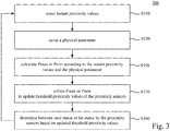
- FIG. 3 is a flow chart diagram illustrating a proximity sensing method 300 according to an embodiment of the disclosure.
- the proximity sensing method 300 is suitable to be used on the electronic system 100 in aforesaid embodiments.
- operation S310 is executed to sense instant proximity values by the proximity sensors 122a-122d disposed on a hand-held controller 120.
- the instant proximity values generated by the proximity sensors 122a-122d are integers in a range from 0 to 100; the instant proximity values will be smaller when the objects are far; and the instant proximity values will be bigger when the objects are near.
- the instant proximity values generated by the proximity sensors 122a-122d can be 24, 16, 86 and 89.
- the instant proximity values generated by the proximity sensors 122a-122d can be 12, 86, 90 and 95.
- the disclosure is not limited thereto.
- a skilled person in the art may configure the instant proximity values in different ranges (e.g., from 0 to 1, from -100 to 100, or from 0 to 10000) and in the opposite correlation relationship (e.g., the instant proximity values will be smaller when the objects are near).
- operation S330 is executed to sense a physical parameter by a physical information sensing circuit 124.
- the physical information sensing circuit 124 can include a touch sensor, a pressure sensor or a temperature sensor.
- the physical information sensing circuit 124 includes a touch sensor for demonstration.
- the touch sensor can be implemented on a lateral side of the hand-held controller 120.
- a palm area of user's hand will contact on the touch sensor (the physical information sensing circuit 124 shown in Fig. 3 ).
- the physical parameter includes a percentage of touched area detected by the touch sensor.
- the percentage of touched area can indicate the user holds the hand-held controller 120 tighter or looser. When the percentage of touched area is higher, it indicates the user holds the hand-held controller 120 tighter.
- the percentage of touched area when the percentage of touched area is lower, it indicates the user holds the hand-held controller 120 looser.
- the percentage of touched area can also indicate a size of user's hand. When the percentage of touched area is higher, the size of user's hand is bigger. On the other hand, when the percentage of touched area is lower, the size of user's hand is smaller.
- the physical parameter can be a pressure reading about how much force the user applies on a surface of the physical information sensing circuit 124.
- the pressure reading can indicate the user holds the hand-held controller 120 tighter or looser.
- the physical parameter can be a temperature reading about a current temperature on a surface of the physical information sensing circuit 124. Because, the human palm will have a temperature around 37 Celsius degree. In this case, if the temperature reading is adjacent to 37 Celsius degree, it indicates the user holds the hand-held controller 120 tight. On the other hand, if the temperature reading is away from 37 Celsius degree, it indicates the user holds the hand-held controller 120 loose or releases the hand-held controller 120.
- Operation S350 is executed to calculate maximum proximity values or minimum proximity values according to the instant proximity values and the physical parameter by the computing application 140.
- Fig. 4 is a flow chart diagram illustrating further operations S351-S355 in the operation S350 shown in Fig. 3 according to some embodiments of the disclosure.
- Table 1 recites aforesaid values in an example in conditions that the user holds the hand-held controller 120 with the hand gesture HG1 shown in Fig. 1A and the percentage of touched area (the physical parameter) equals to 40%.
- Table 1 Proximity sensor 122a 122b 122c 122d Instant proximity value 24 16 86 89 Threshold proximity value in default 50 50 50 50 Current status far far near near Physical parameter 40% 40% 40% 40% Calibration value 20 20 40 40 Pmax 44 36 x x Pmin x x 46 49 Updated threshold proximity value 44 36 46 49
- operation S350 is executed on each one of the proximity sensors 122a-122d respectively.
- the operation S351 is executed to determine a target proximity sensor (122a, 122b, 122c or 122d) from the proximity sensors 122a-122d is currently in near status or far status.
- the threshold proximity value for each one of the proximity sensors 122a-122d can be set in a default value (e.g., 50).
- each of the instant proximity values of the proximity sensors 122a-122d is compared to the threshold proximity value in default to determine whether the target proximity sensor is currently in near status or far status.
- the proximity sensor 122a As shown in Table 1, because the instant proximity value "24" of the proximity sensor 122a is below the threshold proximity value "50" in default, the proximity sensor 122a is currently in far status. Similarly, the proximity sensor 122b is currently in far status. Because, the instant proximity value "86" of the proximity sensor 122c exceeds the threshold proximity value "50" in default, the proximity sensor 122c is currently in near status. Similarly, the proximity sensor 122d is currently in near status.
- operation S352 will be executed to calculate a calibration value in correlated to the physical parameter, which is 40% area being touched on the touch sensor.
- the physical parameter which is 40% area being touched on the touch sensor.
- this physical parameter may indicate the user holds the hand-held controller 120 relatively loose or the size of user's hand is relatively smaller, such that the instant proximity values generated by the proximity sensors 122a-122d tend to be lower.
- the calibration value for the proximity sensor 122a and the proximity sensor 122b in far status are calculated to be "20" by the computing application 140.
- operation S370 is executed by the computing application 140 to utilize the maximum proximity value Pmax "44" to update the threshold proximity value of the proximity sensor 122a.
- the calibration value is added to the instant proximity value to calculate the maximum proximity value Pmax, but the disclosure is not limited thereto.
- the calibration value can be multiplied to the instant proximity value to calculate the maximum proximity value Pmax, and in this case the calibration value can be a positive number ranged from 1.00 to 10.00.
- operation S390 is executed that the proximity sensor 122a will utilize the updated threshold proximity value "44" in determining near status or far status. Afterward, if another instant proximity value is sensed by the proximity sensor 122a in the future exceeds 44, a result of the proximity sensor 122a will switch from far status into near status. If the instant proximity value sensed by the proximity sensor 122a in the future is lower than 44, a result of the proximity sensor 122a will remain in far status.
- the proximity sensor 122a is calibrated to be more sensitive to far status (the threshold proximity value is adjusted from “50” to "44"), so as to calibrate a bias induced by the conditions that the user holds the hand-held controller 120 relatively loose or the size of user's hand is relatively smaller.
- operation S370 is executed to utilize the maximum proximity value "36” to update the threshold proximity value of the proximity sensor 122b.
- operation S390 is executed that the proximity sensor 122b will utilize the updated threshold proximity value "36" in determining near status or far status.
- the proximity sensor 122b is calibrated to be more sensitive to far status (the threshold proximity value is adjusted from “50” to "36"), so as to calibrate a bias induced by the conditions that the user holds the hand-held controller 120 relatively loose or the size of user's hand is relatively smaller.
- the calibration value "20" applied to the proximity sensors 122a and 122b are the same due to the physical parameter, but the maximum proximity values Pmax can be different for the proximity sensors 122a and 122b, because the proximity sensors 122a and 122b have different instant proximity values at first.
- operation S354 will be executed to calculate a calibration value in correlated to the physical parameter, which is 40% area being touched on the touch sensor.
- the physical parameter which is 40% area being touched on the touch sensor.
- this physical parameter may indicate the user holds the hand-held controller 120 relatively loose or the size of user's hand is relatively smaller, such that the instant proximity values generated by the proximity sensors 122a-122d tend to be lower.
- the calibration value for the proximity sensor 122c and the proximity sensor 122d in near status are calculated to be "40" by the computing application 140.
- operation S370 is executed to utilize the minimum proximity value Pmin "46” to update the threshold proximity value of the proximity sensor 122c.
- operation S390 is executed that the proximity sensor 122c will utilize the updated threshold proximity value "46" in determining near status or far status. Afterward, if another instant proximity value is sensed by the proximity sensor 122c in the future exceeds 46, a result of the proximity sensor 122c will remain in near status.
- the calibration value is deducted from the instant proximity value to calculate the minimum proximity value Pmin, but the disclosure is not limited thereto.
- the calibration value can be multiplied to the instant proximity value to calculate the minimum proximity value Pmin, and in this case the calibration value can be a positive number ranged from 0.00 to 1.00.
- the proximity sensor 122c is calibrated to be more sensitive to far status (the threshold proximity value is adjusted from “50” to "46").
- operation S370 is executed to utilize the minimum proximity value Pmin "49” to update the threshold proximity value of the proximity sensor 122d.
- operation S390 is executed that the proximity sensor 122d will utilize the updated threshold proximity value "49" in determining near status or far status.
- the calibration value "40" applied to the proximity sensors 122c and 122d are the same due to the physical parameter, but the minimum proximity value Pmin can be different for the proximity sensors 122c and 122d, because the proximity sensors 122c and 122d have different instant proximity values at first.
- Table 1 shows the example in conditions that the percentage of touched area (the physical parameter) equals to 40%. Reference is further made to Table 2.
- Table 2 recites another example in conditions that the user holds the hand-held controller 120 with the hand gesture HG1 shown in Fig. 1A and the percentage of touched area (the physical parameter) equals to 60%.
- Table 2 Proximity sensor 122a 122b 122c 122d Instant proximity value 24 16 86 89 Threshold proximity value in default 50 50 50 50 50 Current status far far near near Physical parameter 60% 60% 60% 60% Calibration value 40 40 20 20 Pmax 64 56 x x Pmin x x 66 69 Updated threshold proximity value 64 56 66 69
- the example shown in Table 2 is under the conditions that the percentage of touched area equals to 60%. It indicates that the user holds the hand-held controller 120 relatively tighter (compared to the example shown in Table 1) or the size of user's hand is relatively bigger (compared to the example shown in Table 1).
- operation S352 will be executed to calculate a calibration value in correlated to the physical parameter, which is 60% area being touched on the touch sensor.
- the physical parameter which is 60% area being touched on the touch sensor.
- this physical parameter may indicate the user holds the hand-held controller 120 relatively tighter or the size of user's hand is relatively bigger, such that the instant proximity values generated by the proximity sensors 122a-122d tend to be higher.
- the calibration value for the proximity sensor 122a and the proximity sensor 122b in far status are calculated to be "40" by the computing application 140. It is noticed that the calibration value "40" for the proximity sensor 122a and the proximity sensor 122b is now higher (compared to the example shown in Table 1).
- the calibration value for the proximity sensor 122a and the proximity sensor 122b in far status is calculated by the computing application 140 in positively correlated to the percentage of touched area.
- the operation S370 is executed to utilize the maximum proximity value "64” to update the threshold proximity value of the proximity sensor 122a.
- operation S390 is executed that the proximity sensor 122a will utilize the updated threshold proximity value "64" in determining near status or far status.
- operation S370 is executed to utilize the maximum proximity value "56” to update the threshold proximity value of the proximity sensor 122b.
- operation S390 is executed that the proximity sensor 122b will utilize the updated threshold proximity value "56" in determining near status or far status.
- operation S354 will be executed to calculate a calibration value in correlated to the physical parameter, which is 60% area being touched on the touch sensor.
- the calibration value for the proximity sensor 122c and the proximity sensor 122d in near status are calculated to be "20" by the computing application 140.
- the operation S355 will be executed for the proximity sensor 122c and the proximity sensor 122d to calculate the minimum proximity values Pmin "66" and "69”.
- the operation S370 will be executed to update the threshold proximity values for the proximity sensor 122c and the proximity sensor 122d into “66” and “69”.
- Table 1 and Table 2 the calibration value for the proximity sensor 122c and the proximity sensor 122d in near status is calculated by the computing application 140 in negatively correlated to the percentage of touched area.
- Table 3 recites still another example in conditions that the user holds the hand-held controller 120 with the hand gesture HG1 shown in Fig. 1A and the percentage of touched area (the physical parameter) equals to 80%.
- Table 3 Proximity sensor 122a 122b 122c 122d Instant proximity value 24 16 86 89 Threshold proximity value in default 50 50 50 50 50 Current status far far near near Physical parameter 80% 80% 80% 80% Calibration value 45 45 15 15 Pmax 69 61 x x Pmin x x 71 74 Updated threshold proximity value 69 61 71 74
- the calibration value for the proximity sensor 122a and the proximity sensor 122b in far status is calculated by the computing application 140 in positively correlated to the percentage of touched area.
- the calibration value "45” is calculated for the proximity sensor 122a and the proximity sensor 122b corresponding to 80% area being touched.
- the calibration value for the proximity sensor 122c and the proximity sensor 122d in near status is calculated by the computing application 140 in negatively correlated to the percentage of touched area.
- the calibration value "15” is calculated for the proximity sensor 122c and the proximity sensor 122d corresponding to 80% area being touched.
- the operation S370 shown in Fig. 3 is executed to update the threshold proximity values of the proximity sensors 122a-122d with the maximum proximity values Pmax or the minimum proximity values Pmin calculated in the operation S350.
- the threshold proximity values are updated immediately after the maximum proximity values Pmax or the minimum proximity values Pmin are calculated in the operation S350.
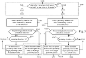
- Fig. 5 is a flow chart diagram illustrating further operations S361-S367 executed between operations S350 and S370 according to some embodiments of the disclosure.
- the proximity sensing method further includes operations S361-S364 after the operation S353.
- the proximity sensors 122a-122d will generate instant proximity values periodically, such as the proximity sensor 122a will generate a new instant proximity value every 0.1 second.
- the maximum proximity values Pmax for the proximity sensor 122a will be calculated in every 0.1 second. After the maximum proximity values Pmax are calculated in the operation S353, the operation S361 is executed to count a persisting duration that the maximum proximity values Pmax continuously remain at the same or similar level. In this case, if the instant proximity value of the proximity sensor 122a remains the same for 0.3 second, the persisting duration will be counted to 3 counts (or 0.3 second). If the instant proximity value of the proximity sensor 122a remains the same or similar for 1 second, the persisting duration will be counted to 10 counts (or 1 second). S362 is executed to determine whether the persisting duration exceeds threshold duration or not. For example, the threshold duration can be set to 5 counts (or 0.5 second). If the persisting duration exceeds threshold duration, the operation S371 will be executed to utilize the maximum proximity values Pmax for the proximity sensor 122a to update the threshold proximity value of the proximity sensor 122a.
- the operation S363 will be executed to determine whether the persisting duration is equal to zero (i.e., an initial stage to set the threshold proximity value) or not. If the persisting duration is equal to zero, the operation S364 will be executed to set the threshold proximity value for the proximity sensor 122a to a default value (e.g., 50) and return to operation S310 for further sensing. If the persisting duration is not equal to zero, the proximity sensing method return to operation S310 for further sensing.
- a default value e.g. 50
- the proximity sensing method further includes operations S365-S368 after the operation S355.
- the minimum proximity values Pmin for the proximity sensor 122c will be calculated in every 0.1 second.
- the operation S365 is executed to count a persisting duration that the minimum proximity values Pmin continuously remain at the same or similar level.
- S366 is executed to determine whether the persisting duration exceeds threshold duration or not. If the persisting duration exceeds threshold duration, the operation S372 will be executed to utilize the minimum proximity values Pmin for the proximity sensor 122c to update the threshold proximity value of the proximity sensor 122c.
- the operation S367 will be executed to determine whether the persisting duration is equal to zero (i.e., an initial stage to set the threshold proximity value) or not. If the persisting duration is equal to zero, the operation S368 will be executed to set the threshold proximity value for the proximity sensor 122c to a default value (e.g., 50) and return to operation S310 for further sensing. If the persisting duration is not equal to zero, the proximity sensing method return to operation S310 for further sensing.
- a default value e.g. 50
- the proximity sensing method will not update the threshold proximity value immediately once the maximum proximity values Pmax or the minimum proximity values Pmin change. Instead, the proximity sensing method will update the threshold proximity value after the maximum proximity values Pmax or the minimum proximity values Pmin change to new levels and then remain steady for a persisting duration. In this case, the threshold proximity value will not be affected by temporary or dramatically changes on few samples of the instant proximity values sensed by the proximity sensors 122a-122d.
- the physical parameter in aforesaid embodiments includes a percentage of touched area detected by the physical information sensing circuit 140 shown in Fig. 2 .
- the percentage of touched area is utilized to calculate the calibration values for the proximity sensors 122a-122d.
- the physical parameter can also include a temperature reading or a pressure reading detected by the physical information sensing circuit 140 shown in Fig. 2 .
- the calibration values can be calculate in correlated with the pressure reading or the temperature reading.
- the proximity sensors 122a-122d utilize one singular percentage of touched area detected by the physical information sensing circuit 140 to calculate the calibration values.
- the disclosure is not limited thereto.
- Fig. 6 is a schematic diagram illustrating an electronic system 600 according to some embodiments of the present disclosure.
- the electronic system 600 includes a hand-held controller 620 and a computing application 640.
- the computing application 640 is executed by a processor 662 of a computing device 660.
- the computing device 660 is communicatively connected through a wireless connection (e.g., WiFi, Bluetooth, BLE or IR) or a wired connection (e.g., via a cable wiring) to the hand-held controller 620.
- the hand-held controller 620 includes a proximity sensing circuit 622 and a physical information sensing circuit 624. In the embodiment shown in Fig.
- the proximity sensing circuit 622 includes four proximity sensors 622a-622d
- the physical information sensing circuit includes four physical information sensors 624a-624d.
- Each of the physical information sensors 624a, 624b, 624c and 624d are disposed corresponding to one of the proximity sensors 622a, 622b, 622c and 622d.
- the physical information sensors 624a is disposed adjacent the proximity sensor 622a
- the physical information sensors 624b is disposed adjacent the proximity sensor 622b
- the physical information sensors 624c is disposed adjacent the proximity sensor 622c
- the physical information sensors 624d is disposed adjacent the proximity sensor 622d.
- the physical parameter includes physical data respectively sensed by the physical information sensors 624a-624d.
- the computing application 640 is configured to calculate calibration values in correlated to the physical data respectively.
- the computing application 640 is configured to calculate the maximum proximity values by adding or multiplying the calibration values respectively to the instant proximity values, or calculate the minimum proximity values by deducting or multiplying the calibration values respectively to the instant proximity values.
- Table 4 recites aforesaid values in an example in conditions the percentages of touched area (the physical parameter) are individually detected by the physical information sensors 624a, 624b, 624c and 624d.
- Table 4 Proximity sensor 622a 622b 622c 622d
- Instant proximity value 24 16 86 89
- Threshold proximity value in default 50 50 50
- Current status far far near near Physical parameter 40% 60%
- 80% Calibration value
- 20 20 15 Pmax 44 56 x x Pmin x x 66 74
- the physical information sensing circuit includes four physical information sensors 624a-624d.
- the physical parameter includes four physical data respectively sensed by the physical information sensors 624a-624d.
- the physical information sensors 624a-624d can be four separated touch sensors as shown in Fig. 6 .
- the physical information sensors 624a-624d can be four sensing areas (not shown in figures) implemented by one touch panel.
- the percentages of touched areas sensed by the physical information sensors 624a-624d are 40%, 60%, 60% and 80%.
- Fig. 7 is a flow chart diagram illustrating further details of operations S330 and S350 shown in Fig. 3 corresponding to embodiments shown in Fig. 6 .
- the operation S330 is executed to sense physical data (40%, 60%, 60% and 80% touched area) respectively by the physical information sensors 624a-624d.
- the operation S352 is executed to calculate a calibration value "20" in correlated to one corresponding physical data (40% touched area).
- the operation S352 is executed to calculate a calibration value "40" in correlated to one corresponding physical data (60% touched area).
- the operation S354 is executed to calculate a calibration value "20" in correlated to one corresponding physical data (60% touched area).
- the operation S354 is executed to calculate a calibration value "15" in correlated to one corresponding physical data (80% touched area).
- the calibration values for the physical information sensors 624a-624d are calculated respectively according to the physical data respectively sensed by the physical information sensors 624a-624d, such that each of the proximity sensors 622a-622d can be calibrated individually according to different physical data.
- the physical parameter is utilized to calculate a calibration value to increase or reduce the maximum proximity value (Pmax) or the minimum proximity value (Pmin), but the disclosure is not limited thereto.
- the physical parameter can be utilized to decide whether to update Pmax/Pmin or not.
- FIG. 8 is a flow chart diagram illustrating further details in one operation S350 shown in Fig. 3 according to some embodiments of the disclosure.
- operation S350 is executed on each one of the proximity sensors 122a-122d respectively.
- the operation S851 is executed to compare the physical parameter with a threshold value.
- the threshold value can be configured as 40% (which means that 40% of whole sensing area of the touch sensor sense a touch contact).
- operation S852 is executed to update the maximum proximity value Pmax of the proximity sensors currently in the near status according to the instant proximity value.
- Table 5 recites aforesaid values in an example in conditions the percentages of touched area (the physical parameter) are 65% over the threshold value.
- Table 5 Proximity sensor 122a 122b 122c 122d Instant proximity value 24 16 86 89 Threshold proximity value in default 50 50 50 50 Current status far far near near Physical parameter 65 65 65 65 65 65 Pmax x x 86 89 Pmin x x x x x x x
- the operation S852 is executed to update the maximum proximity values of the proximity sensor 122c and 122d to be equal to the instant proximity values sensed by the proximity sensors 122c and 122d.
- the maximum proximity value Pmax of the proximity sensor 122c is updated to "86”
- the maximum proximity value Pmax of the proximity sensor 122d is updated to "89”. In this case, the maximum proximity values or minimum proximity values of the proximity sensors 122a and 122b remains unchanged.
- operation S853 is executed to update the minimum proximity value Pmin of the proximity sensors currently in the near status according to the instant proximity value.
- Table 6 recites aforesaid values in an example in conditions the percentages of touched area (the physical parameter) are 25% below the threshold value.
- the updated maximum proximity values on the proximity sensors 122c and 122d can be utilized to update the threshold proximity value of the proximity sensors 122c and 122d in determining near/far event.
- the operation S853 is executed to update the minimum proximity values of the proximity sensors 122a and 122b to be equal to the instant proximity values sensed by the proximity sensors 122a and 122b.
- the minimum proximity value Pmin of the proximity sensor 122a is updated to "24”
- the minimum proximity value Pmin of the proximity sensor 122b is updated to "16”. In this case, the maximum proximity values or minimum proximity values of the proximity sensors 122c and 122d remains unchanged.
- the updated maximum proximity values on the proximity sensors 122a and 122b can be utilized to update the threshold proximity value of the proximity sensors 122a and 122b in determining near/far event.
- the physical parameter can be utilized to decide when and whether to update Pmax/Pmin or not.
- the operation S851-S853 shown in FIG. 8 can be utilized on the embodiment shown in FIG. 6 with individual physical information sensors 624a, 624b, 624c and 624d are disposed corresponding to one of the proximity sensors 622a, 622b, 622c and 622d.
- each of the proximity sensors 622a-622d can update the maximum proximity value or minimum proximity value selectively according to one physical parameter collected by one of the physical information sensors 624a-624d respectively.
Landscapes
- Engineering & Computer Science (AREA)
- Multimedia (AREA)
- Human Computer Interaction (AREA)
- Physics & Mathematics (AREA)
- General Engineering & Computer Science (AREA)
- Theoretical Computer Science (AREA)
- General Physics & Mathematics (AREA)
- Electromagnetism (AREA)
- Computer Networks & Wireless Communication (AREA)
- Radar, Positioning & Navigation (AREA)
- Remote Sensing (AREA)
- User Interface Of Digital Computer (AREA)
- Telephone Function (AREA)
Abstract
Description
- This application claims priority to
U.S. Provisional Application Serial Number 62/508,398, filed on May 19, 2017 - Present disclosure relates to a system and a method for proximity detection. More particularly, the present disclosure relates to a system and a method for calibrating or updating a threshold value of proximity detection.
- Proximity detection is a technology to detect a distance from a proximity sensor to a target object. The proximity sensor may generate a proximity value which reflects the distance. When the proximity value exceeds a threshold, the proximity sensor detects that the target object is near. On the other hand, when the proximity value is below a threshold, the proximity sensor detects that the target object is far. Proximity detection is useful in various applications. For example, the proximity sensor can be disposed on a mobile phone to detect whether the user is adjacent to the phone.
- The disclosure provides an electronic system, which includes a hand-held controller and a computing application. The hand-held controller includes a proximity sensing circuit and a physical information sensing circuit. The proximity sensing circuit includes proximity sensors. The proximity sensors are configured to sense instant proximity values. The physical information sensing circuit is configured to sense a physical parameter. The computing application is executed by a processor. The computing application is configured to retrieve the instant proximity values and the physical parameter, to calculate maximum proximity values or minimum proximity values according to the instant proximity values and the physical parameter. The maximum proximity values or the minimum proximity values are utilized to update threshold proximity values of the proximity sensors in determining near status or far status.
- Another aspect of present disclosure is to provide a proximity sensing method, which include following steps. Instant proximity values are sensed by proximity sensors disposed on a hand-held controller. A physical parameter is sensed by a physical information sensing circuit disposed on the hand-held controller. Maximum proximity values or minimum proximity values are calculated according to the instant proximity values and the physical parameter. The maximum proximity values or the minimum proximity values are utilized to update threshold proximity values of the proximity sensors in determining near status or far status.
- It is to be understood that both the foregoing general description and the following detailed description are by examples, and are intended to provide further explanation of the disclosure as claimed.
- Present disclosure can be more fully understood by reading the following detailed description of the embodiment, with reference made to the accompanying drawings as follows:
-
Fig. 1A is a schematic diagram illustrating an electronic system according to some embodiments of the present disclosure. -
Fig. 1B is another schematic diagram illustrating the electronic system inFig. 1A . -
Fig. 2 is a schematic diagram illustrating a bottom view of the hand-held controller of the electronic system inFig. 1A . -
FIG. 3 is a flow chart diagram illustrating a proximity sensing method according to an embodiment of the disclosure. -
Fig. 4 is a flow chart diagram illustrating further details in one operation shown inFig. 3 according to some embodiments of the disclosure. -
Fig. 5 is a flow chart diagram illustrating further operations executed between two operations shown inFig. 3 according to some embodiments of the disclosure. -
Fig. 6 is a schematic diagram illustrating an electronic system according to some embodiments of the present disclosure. -
Fig. 7 is a flow chart diagram illustrating further details of operations shown inFig. 3 corresponding to embodiments shown inFig. 6 . - Reference will now be made in detail to the present embodiments of the disclosure, examples of which are illustrated in the accompanying drawings. Wherever possible, the same reference numbers are used in the drawings and the description to refer to the same or like parts.
- Reference throughout the specification to "one embodiment" or "an embodiment" means that a particular feature, structure, implementation, or characteristic described in connection with the embodiment is included in at least one embodiment of the present disclosure. Thus, uses of the phrases "in one embodiment" or "in an embodiment" in various places throughout the specification are not necessarily all referring to the same embodiment. Furthermore, the particular features, structures, implementation, or characteristics may be combined in any suitable manner in one or more embodiments.
- Reference is made to
Fig. 1A andFig 1B .Fig. 1A is a schematic diagram illustrating anelectronic system 100 according to some embodiments of the present disclosure.Fig. 1B is another schematic diagram illustrating theelectronic system 100 inFig. 1A . As illustrated inFig. 1A , in one embodiment, theelectronic system 100 includes a hand-heldcontroller 120 and acomputing application 140. In the embodiment shown inFig. 1A , thecomputing application 140 is executed by aprocessor 162 of acomputing device 160. Thecomputing device 160 is communicatively connected through a wireless connection (e.g., WiFi, Bluetooth, BLE or IR) or a wired connection (e.g., via a cable wiring) to the hand-heldcontroller 120. - In some embodiments, the
computing device 160 can be a computer, a game console, a server or any equivalent device with computation ability. Theprocessor 162 may be a CPU, GPU, ASIC or some control unit of thecomputing device 160, and thecomputing application 140 may be software or firmware executed by theprocessor 162. However, theelectronic system 100 is not limited to include thecomputing device 160 and theprocessor 162 separated from the hand-heldcontroller 120. In some other embodiments, thecomputing application 140 can be executed by a processor (not shown in figures) disposed in the hand-heldcontroller 120. - Reference is also made to
Fig. 2 , which is a schematic diagram illustrating a bottom view of the hand-heldcontroller 120 of theelectronic system 100 inFig. 1A . As shown inFig. 2 , the hand-heldcontroller 120 includes aproximity sensing circuit 122 and a physicalinformation sensing circuit 124. In the embodiment shown inFig. 1A ,Fig. 1B andFig. 2 , theproximity sensing circuit 122 include fourproximity sensors proximity sensors proximity sensors - When the hand-held
controller 120 is held by a hand (referring toFig. 1A andFig. 1B ), theproximity sensors proximity sensor 122a is configured to detect a finger position of an index finger. Theproximity sensor 122b is configured to detect a finger position of a middle finger. Theproximity sensor 122c is configured to detect a finger position of a ring finger. Theproximity sensor 122d is configured to detect a finger position of a little finger. In other words, theproximity sensing circuit 122 includes theproximity sensors controller 120 is hold by a user's hand. - However, the
proximity sensing circuit 122 is not limited to include fourproximity sensors Fig. 1A ,Fig. 1B andFig. 2 . In other embodiments, theproximity sensing circuit 122 may include more proximity sensors (e.g., five proximity sensors to cover thumb, index, middle, ring and little fingers) or fewer proximity sensors (e.g., three proximity sensors to cover middle, ring and little fingers). - As shown in
Fig. 1A , theproximity sensors proximity sensors proximity sensing circuit 122 can detect the hand gesture HG1 (the index finger and the middle finger are pointing out, and the ring finger and the little finger are grasping on the hand-held controller 120) inFig. 1A . - Similarly, as shown in
Fig. 1B , theproximity sensor 122a will detect that the index finger is far, and theproximity sensors proximity sensing circuit 122 can detect the hand gesture HG2 (the index finger is pointing out, and the middle finger, the ring finger and the little finger are grasping on the hand-held controller 120) inFig. 1B . - Each of the
proximity sensors 122a-122d may generate an instant proximity value which reflects a gap distance from the proximity sensor (122a, 122b, 122c or 122d) to a target object (e.g., a corresponding finger). When the instant proximity value exceeds or closes to a maximal threshold proximity value, theproximity sensor proximity sensor - In some embodiments, the instant proximity value generated by the
proximity sensors proximity sensors 122a-122d are detecting finger positions while the hand-heldcontroller 120 is held by a hand. For example, the finger positions corresponding to the same hand gesture (e.g., the hand gesture HG1 inFig. 1A ) detected by theproximity sensors - In some embodiment, the
electronic system 100 is configured to calculate a calibration value to update the threshold proximity values of theproximity sensors 122a-122d in determining near status or far status. As shown inFig. 2 , the hand-heldcontroller 120 includes a physicalinformation sensing circuit 124. The physicalinformation sensing circuit 124 is configured to sense a physical parameter. The physical parameter is related to some conditions (e.g., the user grips the hand-heldcontroller 120 tighter or looser, a size of the user hand or a holding position of the user hand) which will affect the instant proximity values generated by theproximity sensors 122a-122d. - The
computing application 140 is configured to retrieve the instant proximity values from theproximity sensors 122a-122d and the physical parameter from the physicalinformation sensing circuit 124. Thecomputing application 140 is configured to calculate maximum proximity values or minimum proximity values according to the instant proximity values and the physical parameter. In this case, the maximum proximity values or minimum proximity values calculated by thecomputing application 140 are calibrated according to the physical parameter. The maximum proximity values or the minimum proximity values are utilized to update the threshold proximity values of theproximity sensors 122a-122d in determining near status or far status. Details about how to calculate maximum proximity values or minimum proximity values will be introduced in following paragraphs. - In this case, the threshold proximity values of the
proximity sensors 122a-122d in determining near status or far status can be dynamically updated in response to variance of the physical parameter. Theproximity sensors 122a-122d will have higher preciseness in determining near status or far status. - In the embodiment shown in
Fig. 1A , the hand-heldcontroller 120 is held by the right hand of the user. Theelectronic system 100 is able to detect the hand gesture on the right hand of the user. However, the disclosure is not limited thereto. In another embodiment, when the hand-heldcontroller 120 is held by the left hand of the user, theelectronic system 100 is able to detect the hand gesture on the left hand of the user. - In still another embodiment, the
electronic system 100 includes a pair of two hand-held controllers (not shown inFig. 1A ), and these two hand-held controllers are hold respectively by both hands of the user. In this embodiment, theelectronic system 100 is able to detect the hand gestures on both hands of the user. - Reference is also made to
FIG. 3 , which is a flow chart diagram illustrating aproximity sensing method 300 according to an embodiment of the disclosure. Theproximity sensing method 300 is suitable to be used on theelectronic system 100 in aforesaid embodiments. - Referring to
Fig. 1A ,Fig. 2 , andFig. 3 , operation S310 is executed to sense instant proximity values by theproximity sensors 122a-122d disposed on a hand-heldcontroller 120. In order to demonstrating this disclosure, it assumed that the instant proximity values generated by theproximity sensors 122a-122d are integers in a range from 0 to 100; the instant proximity values will be smaller when the objects are far; and the instant proximity values will be bigger when the objects are near. Corresponding to the hand gesture HG1 inFig. 1A , the instant proximity values generated by theproximity sensors 122a-122d can be 24, 16, 86 and 89. Corresponding to the hand gesture HG2 inFig. 1B , the instant proximity values generated by theproximity sensors 122a-122d can be 12, 86, 90 and 95. - However, the disclosure is not limited thereto. In some other embodiments, a skilled person in the art may configure the instant proximity values in different ranges (e.g., from 0 to 1, from -100 to 100, or from 0 to 10000) and in the opposite correlation relationship (e.g., the instant proximity values will be smaller when the objects are near).
- Referring to
Fig. 1A ,Fig. 2 , andFig. 3 , operation S330 is executed to sense a physical parameter by a physicalinformation sensing circuit 124. In some embodiment, the physicalinformation sensing circuit 124 can include a touch sensor, a pressure sensor or a temperature sensor. - In the embodiment shown in
Fig. 1A andFig. 1B , the physicalinformation sensing circuit 124 includes a touch sensor for demonstration. The touch sensor can be implemented on a lateral side of the hand-heldcontroller 120. When the user holds the hand-heldcontroller 120, a palm area of user's hand will contact on the touch sensor (the physicalinformation sensing circuit 124 shown inFig. 3 ). In this case, the physical parameter includes a percentage of touched area detected by the touch sensor. In an embodiment, the percentage of touched area can indicate the user holds the hand-heldcontroller 120 tighter or looser. When the percentage of touched area is higher, it indicates the user holds the hand-heldcontroller 120 tighter. On the other hand, when the percentage of touched area is lower, it indicates the user holds the hand-heldcontroller 120 looser. In another embodiment, the percentage of touched area can also indicate a size of user's hand. When the percentage of touched area is higher, the size of user's hand is bigger. On the other hand, when the percentage of touched area is lower, the size of user's hand is smaller. - When the physical
information sensing circuit 124 includes the pressure sensor, the physical parameter can be a pressure reading about how much force the user applies on a surface of the physicalinformation sensing circuit 124. In this case, the pressure reading can indicate the user holds the hand-heldcontroller 120 tighter or looser. - When the physical
information sensing circuit 124 includes the temperature sensor, the physical parameter can be a temperature reading about a current temperature on a surface of the physicalinformation sensing circuit 124. Because, the human palm will have a temperature around 37 Celsius degree. In this case, if the temperature reading is adjacent to 37 Celsius degree, it indicates the user holds the hand-heldcontroller 120 tight. On the other hand, if the temperature reading is away from 37 Celsius degree, it indicates the user holds the hand-heldcontroller 120 loose or releases the hand-heldcontroller 120. - Operation S350 is executed to calculate maximum proximity values or minimum proximity values according to the instant proximity values and the physical parameter by the
computing application 140. Reference to further made toFig. 4 , which is a flow chart diagram illustrating further operations S351-S355 in the operation S350 shown inFig. 3 according to some embodiments of the disclosure. - In order to demonstrating relationships between the instant proximity values, the physical parameter and maximum proximity values or minimum proximity values calculated by the
computing application 140, Table 1 recites aforesaid values in an example in conditions that the user holds the hand-heldcontroller 120 with the hand gesture HG1 shown inFig. 1A and the percentage of touched area (the physical parameter) equals to 40%.Table 1 Proximity sensor 122a 122b 122c 122d Instant proximity value 24 16 86 89 Threshold proximity value in default 50 50 50 50 Current status far far near near Physical parameter 40% 40% 40% 40% Calibration value 20 20 40 40 Pmax 44 36 x x Pmin x x 46 49 Updated threshold proximity value 44 36 46 49 - As the embodiment shown in
Fig. 1A andFig. 4 , operation S350 is executed on each one of theproximity sensors 122a-122d respectively. The operation S351 is executed to determine a target proximity sensor (122a, 122b, 122c or 122d) from theproximity sensors 122a-122d is currently in near status or far status. Initially, the threshold proximity value for each one of theproximity sensors 122a-122d can be set in a default value (e.g., 50). Before the threshold proximity value is updated, each of the instant proximity values of theproximity sensors 122a-122d is compared to the threshold proximity value in default to determine whether the target proximity sensor is currently in near status or far status. As shown in Table 1, because the instant proximity value "24" of theproximity sensor 122a is below the threshold proximity value "50" in default, theproximity sensor 122a is currently in far status. Similarly, theproximity sensor 122b is currently in far status. Because, the instant proximity value "86" of theproximity sensor 122c exceeds the threshold proximity value "50" in default, theproximity sensor 122c is currently in near status. Similarly, theproximity sensor 122d is currently in near status. - For the
proximity sensor 122a and theproximity sensor 122b in far status, operation S352 will be executed to calculate a calibration value in correlated to the physical parameter, which is 40% area being touched on the touch sensor. In this case, there is 40% area covered by user palm, and this physical parameter may indicate the user holds the hand-heldcontroller 120 relatively loose or the size of user's hand is relatively smaller, such that the instant proximity values generated by theproximity sensors 122a-122d tend to be lower. In this case, the calibration value for theproximity sensor 122a and theproximity sensor 122b in far status are calculated to be "20" by thecomputing application 140. - For the
proximity sensor 122a in far status, operation S353 will be executed to add the calibration value "20" to the instant proximity value "24" to calculate a maximum proximity value Pmax "24 + 20= 44" for theproximity sensor 122a. Referring toFig. 3 , afterward, operation S370 is executed by thecomputing application 140 to utilize the maximum proximity value Pmax "44" to update the threshold proximity value of theproximity sensor 122a. In aforesaid embodiment, the calibration value is added to the instant proximity value to calculate the maximum proximity value Pmax, but the disclosure is not limited thereto. In another embodiment, the calibration value can be multiplied to the instant proximity value to calculate the maximum proximity value Pmax, and in this case the calibration value can be a positive number ranged from 1.00 to 10.00. - After the threshold proximity value is updated, operation S390 is executed that the
proximity sensor 122a will utilize the updated threshold proximity value "44" in determining near status or far status. Afterward, if another instant proximity value is sensed by theproximity sensor 122a in the future exceeds 44, a result of theproximity sensor 122a will switch from far status into near status. If the instant proximity value sensed by theproximity sensor 122a in the future is lower than 44, a result of theproximity sensor 122a will remain in far status. - In this case, the
proximity sensor 122a is calibrated to be more sensitive to far status (the threshold proximity value is adjusted from "50" to "44"), so as to calibrate a bias induced by the conditions that the user holds the hand-heldcontroller 120 relatively loose or the size of user's hand is relatively smaller. - For the
proximity sensor 122b in far status, operation S353 will be executed to add the calibration value "20" to the instant proximity value "16" to calculate a maximum proximity value Pmax "16 + 20= 36" for theproximity sensor 122b. Referring toFig. 3 , afterward, operation S370 is executed to utilize the maximum proximity value "36" to update the threshold proximity value of theproximity sensor 122b. After the threshold proximity value is updated, operation S390 is executed that theproximity sensor 122b will utilize the updated threshold proximity value "36" in determining near status or far status. - In this case, the
proximity sensor 122b is calibrated to be more sensitive to far status (the threshold proximity value is adjusted from "50" to "36"), so as to calibrate a bias induced by the conditions that the user holds the hand-heldcontroller 120 relatively loose or the size of user's hand is relatively smaller. In this case, the calibration value "20" applied to theproximity sensors proximity sensors proximity sensors - For the
proximity sensor 122c and theproximity sensor 122d in near status, operation S354 will be executed to calculate a calibration value in correlated to the physical parameter, which is 40% area being touched on the touch sensor. In this case, there is 40% area covered by user palm, and this physical parameter may indicate the user holds the hand-heldcontroller 120 relatively loose or the size of user's hand is relatively smaller, such that the instant proximity values generated by theproximity sensors 122a-122d tend to be lower. In this case, the calibration value for theproximity sensor 122c and theproximity sensor 122d in near status are calculated to be "40" by thecomputing application 140. - For the
proximity sensor 122c in near status, operation S355 will be executed to deduct the calibration value "40" from the instant proximity value "86" to calculate a minimum proximity value Pmin "86 - 40= 46" for theproximity sensor 122c. Referring toFig. 3 , afterward, operation S370 is executed to utilize the minimum proximity value Pmin "46" to update the threshold proximity value of theproximity sensor 122c. After the threshold proximity value is updated, operation S390 is executed that theproximity sensor 122c will utilize the updated threshold proximity value "46" in determining near status or far status. Afterward, if another instant proximity value is sensed by theproximity sensor 122c in the future exceeds 46, a result of theproximity sensor 122c will remain in near status. If another instant proximity value is sensed by theproximity sensor 122c is lower than 46, a result of theproximity sensor 122c will remain in far status. In aforesaid embodiment, the calibration value is deducted from the instant proximity value to calculate the minimum proximity value Pmin, but the disclosure is not limited thereto. In another embodiment, the calibration value can be multiplied to the instant proximity value to calculate the minimum proximity value Pmin, and in this case the calibration value can be a positive number ranged from 0.00 to 1.00. - In this case, the
proximity sensor 122c is calibrated to be more sensitive to far status (the threshold proximity value is adjusted from "50" to "46"). - For the
proximity sensor 122d in near status, operation S355 will be executed to deduct the calibration value "40" from the instant proximity value "89" to calculate a minimum proximity value Pmin "89 - 40= 49" for theproximity sensor 122d. Referring toFig. 3 , afterward, operation S370 is executed to utilize the minimum proximity value Pmin "49" to update the threshold proximity value of theproximity sensor 122d. After the threshold proximity value is updated, operation S390 is executed that theproximity sensor 122d will utilize the updated threshold proximity value "49" in determining near status or far status. - In this case, the calibration value "40" applied to the
proximity sensors proximity sensors proximity sensors - Aforesaid embodiment in Table 1 shows the example in conditions that the percentage of touched area (the physical parameter) equals to 40%. Reference is further made to Table 2. Table 2 recites another example in conditions that the user holds the hand-held
controller 120 with the hand gesture HG1 shown inFig. 1A and the percentage of touched area (the physical parameter) equals to 60%.Table 2 Proximity sensor 122a 122b 122c 122d Instant proximity value 24 16 86 89 Threshold proximity value in default 50 50 50 50 Current status far far near near Physical parameter 60% 60% 60% 60% Calibration value 40 40 20 20 Pmax 64 56 x x Pmin x x 66 69 Updated threshold proximity value 64 56 66 69 - Compared to Table 1, the example shown in Table 2 is under the conditions that the percentage of touched area equals to 60%. It indicates that the user holds the hand-held
controller 120 relatively tighter (compared to the example shown in Table 1) or the size of user's hand is relatively bigger (compared to the example shown in Table 1). - For the
proximity sensor 122a and theproximity sensor 122b in far status, operation S352 will be executed to calculate a calibration value in correlated to the physical parameter, which is 60% area being touched on the touch sensor. In this case, there is 60% area covered by user palm, and this physical parameter may indicate the user holds the hand-heldcontroller 120 relatively tighter or the size of user's hand is relatively bigger, such that the instant proximity values generated by theproximity sensors 122a-122d tend to be higher. In this case, the calibration value for theproximity sensor 122a and theproximity sensor 122b in far status are calculated to be "40" by thecomputing application 140. It is noticed that the calibration value "40" for theproximity sensor 122a and theproximity sensor 122b is now higher (compared to the example shown in Table 1). - As shown in Table 1 and Table 2, the calibration value for the
proximity sensor 122a and theproximity sensor 122b in far status is calculated by thecomputing application 140 in positively correlated to the percentage of touched area. - For the
proximity sensor 122a in far status, operation S353 is executed to add the calibration value "40" to the instant proximity value "24" to calculate a maximum proximity value Pmax "24 + 40= 64" for theproximity sensor 122a. The operation S370 is executed to utilize the maximum proximity value "64" to update the threshold proximity value of theproximity sensor 122a. After the threshold proximity value is updated, operation S390 is executed that theproximity sensor 122a will utilize the updated threshold proximity value "64" in determining near status or far status. - For the
proximity sensor 122b in far status, operation S353 is executed to add the calibration value "40" to the instant proximity value "16" to calculate a maximum proximity value Pmax "16 + 40= 56" for theproximity sensor 122b. Similarly, operation S370 is executed to utilize the maximum proximity value "56" to update the threshold proximity value of theproximity sensor 122b. After the threshold proximity value is updated, operation S390 is executed that theproximity sensor 122b will utilize the updated threshold proximity value "56" in determining near status or far status. - For the
proximity sensor 122c and theproximity sensor 122d in near status, operation S354 will be executed to calculate a calibration value in correlated to the physical parameter, which is 60% area being touched on the touch sensor. In this case, the calibration value for theproximity sensor 122c and theproximity sensor 122d in near status are calculated to be "20" by thecomputing application 140. Similarly, the operation S355 will be executed for theproximity sensor 122c and theproximity sensor 122d to calculate the minimum proximity values Pmin "66" and "69". The operation S370 will be executed to update the threshold proximity values for theproximity sensor 122c and theproximity sensor 122d into "66" and "69". As shown in Table 1 and Table 2, the calibration value for theproximity sensor 122c and theproximity sensor 122d in near status is calculated by thecomputing application 140 in negatively correlated to the percentage of touched area. - Table 3 recites still another example in conditions that the user holds the hand-held
controller 120 with the hand gesture HG1 shown inFig. 1A and the percentage of touched area (the physical parameter) equals to 80%.Table 3 Proximity sensor 122a 122b 122c 122d Instant proximity value 24 16 86 89 Threshold proximity value in default 50 50 50 50 Current status far far near near Physical parameter 80% 80% 80% 80% Calibration value 45 45 15 15 Pmax 69 61 x x Pmin x x 71 74 Updated threshold proximity value 69 61 71 74 - As shown in Table 1, Table 2 and Table 3, the calibration value for the
proximity sensor 122a and theproximity sensor 122b in far status is calculated by thecomputing application 140 in positively correlated to the percentage of touched area. The calibration value "45" is calculated for theproximity sensor 122a and theproximity sensor 122b corresponding to 80% area being touched. The calibration value for theproximity sensor 122c and theproximity sensor 122d in near status is calculated by thecomputing application 140 in negatively correlated to the percentage of touched area. The calibration value "15" is calculated for theproximity sensor 122c and theproximity sensor 122d corresponding to 80% area being touched. - In aforesaid embodiment, the operation S370 shown in
Fig. 3 is executed to update the threshold proximity values of theproximity sensors 122a-122d with the maximum proximity values Pmax or the minimum proximity values Pmin calculated in the operation S350. - In one embodiment, the threshold proximity values are updated immediately after the maximum proximity values Pmax or the minimum proximity values Pmin are calculated in the operation S350.
- In another embodiment, the threshold proximity values will not be updated immediately after the maximum proximity values Pmax or the minimum proximity values Pmin are calculated in the operation S350. Reference is further made to
Fig. 5 , which is a flow chart diagram illustrating further operations S361-S367 executed between operations S350 and S370 according to some embodiments of the disclosure. - As the embodiments shown in
Fig. 5 , the proximity sensing method further includes operations S361-S364 after the operation S353. In some embodiment, theproximity sensors 122a-122d will generate instant proximity values periodically, such as theproximity sensor 122a will generate a new instant proximity value every 0.1 second. - For example, the maximum proximity values Pmax for the
proximity sensor 122a will be calculated in every 0.1 second. After the maximum proximity values Pmax are calculated in the operation S353, the operation S361 is executed to count a persisting duration that the maximum proximity values Pmax continuously remain at the same or similar level. In this case, if the instant proximity value of theproximity sensor 122a remains the same for 0.3 second, the persisting duration will be counted to 3 counts (or 0.3 second). If the instant proximity value of theproximity sensor 122a remains the same or similar for 1 second, the persisting duration will be counted to 10 counts (or 1 second). S362 is executed to determine whether the persisting duration exceeds threshold duration or not. For example, the threshold duration can be set to 5 counts (or 0.5 second). If the persisting duration exceeds threshold duration, the operation S371 will be executed to utilize the maximum proximity values Pmax for theproximity sensor 122a to update the threshold proximity value of theproximity sensor 122a. - If the persisting duration is below the threshold duration, the operation S363 will be executed to determine whether the persisting duration is equal to zero (i.e., an initial stage to set the threshold proximity value) or not. If the persisting duration is equal to zero, the operation S364 will be executed to set the threshold proximity value for the
proximity sensor 122a to a default value (e.g., 50) and return to operation S310 for further sensing. If the persisting duration is not equal to zero, the proximity sensing method return to operation S310 for further sensing. - On the other hand, as the embodiments shown in
Fig. 5 , the proximity sensing method further includes operations S365-S368 after the operation S355. For example, the minimum proximity values Pmin for theproximity sensor 122c will be calculated in every 0.1 second. After the minimum proximity values Pmin are calculated in the operation S355, the operation S365 is executed to count a persisting duration that the minimum proximity values Pmin continuously remain at the same or similar level. S366 is executed to determine whether the persisting duration exceeds threshold duration or not. If the persisting duration exceeds threshold duration, the operation S372 will be executed to utilize the minimum proximity values Pmin for theproximity sensor 122c to update the threshold proximity value of theproximity sensor 122c. - If the persisting duration is below the threshold duration, the operation S367 will be executed to determine whether the persisting duration is equal to zero (i.e., an initial stage to set the threshold proximity value) or not. If the persisting duration is equal to zero, the operation S368 will be executed to set the threshold proximity value for the
proximity sensor 122c to a default value (e.g., 50) and return to operation S310 for further sensing. If the persisting duration is not equal to zero, the proximity sensing method return to operation S310 for further sensing. - Based on the operation S361-S368 shown in
Fig. 5 , the proximity sensing method will not update the threshold proximity value immediately once the maximum proximity values Pmax or the minimum proximity values Pmin change. Instead, the proximity sensing method will update the threshold proximity value after the maximum proximity values Pmax or the minimum proximity values Pmin change to new levels and then remain steady for a persisting duration. In this case, the threshold proximity value will not be affected by temporary or dramatically changes on few samples of the instant proximity values sensed by theproximity sensors 122a-122d. - The physical parameter in aforesaid embodiments includes a percentage of touched area detected by the physical
information sensing circuit 140 shown inFig. 2 . The percentage of touched area is utilized to calculate the calibration values for theproximity sensors 122a-122d. However, the disclosure is not limited thereto. The physical parameter can also include a temperature reading or a pressure reading detected by the physicalinformation sensing circuit 140 shown inFig. 2 . The calibration values can be calculate in correlated with the pressure reading or the temperature reading. - In aforesaid embodiment, the
proximity sensors 122a-122d utilize one singular percentage of touched area detected by the physicalinformation sensing circuit 140 to calculate the calibration values. However, the disclosure is not limited thereto. - Reference is also made to
Fig. 6 , which is a schematic diagram illustrating anelectronic system 600 according to some embodiments of the present disclosure. As illustrated inFig. 6 , in one embodiment, theelectronic system 600 includes a hand-heldcontroller 620 and acomputing application 640. Thecomputing application 640 is executed by aprocessor 662 of acomputing device 660. Thecomputing device 660 is communicatively connected through a wireless connection (e.g., WiFi, Bluetooth, BLE or IR) or a wired connection (e.g., via a cable wiring) to the hand-heldcontroller 620. The hand-heldcontroller 620 includes aproximity sensing circuit 622 and a physicalinformation sensing circuit 624. In the embodiment shown inFig. 6 , theproximity sensing circuit 622 includes fourproximity sensors 622a-622d, and the physical information sensing circuit includes fourphysical information sensors 624a-624d. Each of thephysical information sensors proximity sensors physical information sensors 624a is disposed adjacent theproximity sensor 622a; thephysical information sensors 624b is disposed adjacent theproximity sensor 622b; thephysical information sensors 624c is disposed adjacent theproximity sensor 622c; and thephysical information sensors 624d is disposed adjacent theproximity sensor 622d. - The physical parameter includes physical data respectively sensed by the
physical information sensors 624a-624d. Thecomputing application 640 is configured to calculate calibration values in correlated to the physical data respectively. Thecomputing application 640 is configured to calculate the maximum proximity values by adding or multiplying the calibration values respectively to the instant proximity values, or calculate the minimum proximity values by deducting or multiplying the calibration values respectively to the instant proximity values. - In order to demonstrating relationships between the instant proximity values, the physical parameter and maximum proximity values or minimum proximity values calculated by the
computing application 640, Table 4 recites aforesaid values in an example in conditions the percentages of touched area (the physical parameter) are individually detected by thephysical information sensors Table 4 Proximity sensor 622a 622b 622c 622d Instant proximity value 24 16 86 89 Threshold proximity value in default 50 50 50 50 Current status far far near near Physical parameter 40% 60% 60% 80% Calibration value 20 40 20 15 Pmax 44 56 x x Pmin x x 66 74 Updated threshold proximity value 44 56 66 74 - As shown in
Fig. 6 and Table 4, the physical information sensing circuit includes fourphysical information sensors 624a-624d. The physical parameter includes four physical data respectively sensed by thephysical information sensors 624a-624d. In an embodiment, thephysical information sensors 624a-624d can be four separated touch sensors as shown inFig. 6 . In another embodiment, thephysical information sensors 624a-624d can be four sensing areas (not shown in figures) implemented by one touch panel. In the example shown in Table 4, the percentages of touched areas sensed by thephysical information sensors 624a-624d are 40%, 60%, 60% and 80%. - Reference is further made to
Fig. 7 , which is a flow chart diagram illustrating further details of operations S330 and S350 shown inFig. 3 corresponding to embodiments shown inFig. 6 . As shown inFig. 7 , the operation S330 is executed to sense physical data (40%, 60%, 60% and 80% touched area) respectively by thephysical information sensors 624a-624d. - For the
physical information sensors 624a in far status, the operation S352 is executed to calculate a calibration value "20" in correlated to one corresponding physical data (40% touched area). The operation S353 is executed to add the calibration value "20" to the instant proximity value "24" for calculating the maximum proximity value Pmax "24 + 20 = 44". - For the
physical information sensors 624b in far status, the operation S352 is executed to calculate a calibration value "40" in correlated to one corresponding physical data (60% touched area). The operation S353 is executed to add the calibration value "40" to the instant proximity value "16" for calculating the maximum proximity value Pmax "16 + 40 = 56". - For the
physical information sensors 624c in near status, the operation S354 is executed to calculate a calibration value "20" in correlated to one corresponding physical data (60% touched area). The operation S355 is executed to deduct the calibration value "20" from the instant proximity value "86" for calculating the minimum proximity value Pmin "86 - 20 = 66". - For the
physical information sensors 624d in near status, the operation S354 is executed to calculate a calibration value "15" in correlated to one corresponding physical data (80% touched area). The operation S355 is executed to deduct the calibration value "15" from the instant proximity value "89" for calculating the minimum proximity value Pmin "89 - 15 = 74". - Based on
Fig. 6 andFig. 7 , the calibration values for thephysical information sensors 624a-624d are calculated respectively according to the physical data respectively sensed by thephysical information sensors 624a-624d, such that each of theproximity sensors 622a-622d can be calibrated individually according to different physical data. - In aforesaid embodiments as shown in
FIG. 4 ,FIG. 5 andFIG. 7 , the physical parameter is utilized to calculate a calibration value to increase or reduce the maximum proximity value (Pmax) or the minimum proximity value (Pmin), but the disclosure is not limited thereto. - In some other embodiments, the physical parameter can be utilized to decide whether to update Pmax/Pmin or not. Reference is further made to
FIG. 8 , which is a flow chart diagram illustrating further details in one operation S350 shown inFig. 3 according to some embodiments of the disclosure. - As the embodiment shown in
Fig. 1A andFig. 8 , operation S350 is executed on each one of theproximity sensors 122a-122d respectively. The operation S851 is executed to compare the physical parameter with a threshold value. For example, when the physical parameter is a percentage of touched area detected by the touch sensor, the threshold value can be configured as 40% (which means that 40% of whole sensing area of the touch sensor sense a touch contact). - When the physical parameter exceeds the threshold value (more than 40% of whole sensing area of the touch sensor sense a touch contact), operation S852 is executed to update the maximum proximity value Pmax of the proximity sensors currently in the near status according to the instant proximity value. In order to demonstrating relationships between the instant proximity values, the physical parameter and maximum proximity values or minimum proximity values, Table 5 recites aforesaid values in an example in conditions the percentages of touched area (the physical parameter) are 65% over the threshold value.
Table 5 Proximity sensor 122a 122b 122c 122d Instant proximity value 24 16 86 89 Threshold proximity value in default 50 50 50 50 Current status far far near near Physical parameter 65 65 65 65 Pmax x x 86 89 Pmin x x x x - As shown in
FIG. 8 and Table 5, when the physical parameter is detected to be 65% (which means the user may grip the hand-heldcontroller 120 tighter), the operation S852 is executed to update the maximum proximity values of theproximity sensor proximity sensors proximity sensor 122c is updated to "86", and the maximum proximity value Pmax of theproximity sensor 122d is updated to "89". In this case, the maximum proximity values or minimum proximity values of theproximity sensors - On the other hand, when the physical parameter is lower the threshold value (more than 40% of whole sensing area of the touch sensor sense a touch contact), operation S853 is executed to update the minimum proximity value Pmin of the proximity sensors currently in the near status according to the instant proximity value. In order to demonstrating relationships between the instant proximity values, the physical parameter and maximum proximity values or minimum proximity values, Table 6 recites aforesaid values in an example in conditions the percentages of touched area (the physical parameter) are 25% below the threshold value. The updated maximum proximity values on the
proximity sensors proximity sensors Table 6 Proximity sensor 122a 122b 122c 122d Instant proximity value 24 16 86 89 Threshold proximity value in default 50 50 50 50 Current status far far near near Physical parameter 25 25 25 25 Pmax x x x x Pmin 24 16 x x - As shown in
FIG. 8 and Table 6, when the physical parameter is detected to be 25% (which means the user may grip the hand-heldcontroller 120 looser), the operation S853 is executed to update the minimum proximity values of theproximity sensors proximity sensors proximity sensor 122a is updated to "24", and the minimum proximity value Pmin of theproximity sensor 122b is updated to "16". In this case, the maximum proximity values or minimum proximity values of theproximity sensors proximity sensors proximity sensors FIG. 8 , the physical parameter can be utilized to decide when and whether to update Pmax/Pmin or not. - In another embodiment, the operation S851-S853 shown in
FIG. 8 can be utilized on the embodiment shown inFIG. 6 with individualphysical information sensors proximity sensors proximity sensors 622a-622d can update the maximum proximity value or minimum proximity value selectively according to one physical parameter collected by one of thephysical information sensors 624a-624d respectively. - Although the present disclosure has been described in considerable detail with reference to certain embodiments thereof, other embodiments are possible. Therefore, the spirit and scope of the appended claims should not be limited to the description of the embodiments contained herein.
- It will be apparent to those skilled in the art that various modifications and variations can be made to the structure of the present disclosure without departing from the scope or spirit of the disclosure. In view of the foregoing, it is intended that the present disclosure cover modifications and variations of this disclosure provided they fall within the scope of the following claims.
Claims (15)
- An electronic system, comprising:a hand-held controller comprising:a proximity sensing circuit comprising a plurality of proximity sensors, the proximity sensors being configured to sense a plurality of instant proximity values; anda physical information sensing circuit configured to sense a physical parameter;a computing application, executed by a processor, configured to retrieve the instant proximity values and the physical parameter, to calculate a plurality of maximum proximity values or minimum proximity values according to the instant proximity values and the physical parameter, the maximum proximity values or the minimum proximity values being utilized to update a plurality of threshold proximity values of the proximity sensors in determining near status or far status.
- The electronic system of claim 1, wherein the computing application is configured to calculate the maximum proximity values by adding or multiplying a calibration value to the instant proximity values, the calibration value is calculated by the computing application in correlated to the physical parameter.
- The electronic system of claim 2, wherein the physical information sensing circuit comprises a touch sensor, and the physical parameter comprises a percentage of touched area detected by the touch sensor, the calibration value is calculated by the computing application in positively correlated to the percentage of touched area.
- The electronic system of claim 1 or 2, wherein the physical information sensing circuit comprises a pressure sensor or a temperature sensor, the physical parameter comprises a pressure reading of the pressure sensor or a temperature reading of the temperature sensor.
- The electronic system of any one of the preceding claims, wherein the physical information sensing circuit comprises a plurality of physical information sensors, each of the physical information sensors are disposed corresponding to one of the proximity sensors, and the physical parameter comprises physical data respectively sensed by the physical information sensors, the computing application is configured to calculate the maximum proximity values by adding a plurality of calibration values respectively to the instant proximity values, the calibration values are calculated by the computing application in correlated to the physical data respectively.
- The electronic system of any one of the preceding claims, wherein the computing application is configured to calculate the minimum proximity values by deducting or multiplying a calibration value to the instant proximity values, the calibration value is calculated by the computing application in correlated to the physical parameter.
- The electronic system of any one of the preceding claims, wherein the computing application is configured to update the threshold proximity values of the proximity sensors in response to that the maximum proximity values or minimum proximity values continuously remain at the same level for a persisting duration.
- A proximity sensing method, comprising:sensing a plurality of instant proximity values by a plurality of proximity sensors disposed on a hand-held controller;sensing a physical parameter by a physical information sensing circuit disposed on the hand-held controller;calculating a plurality of maximum proximity values or minimum proximity values according to the instant proximity values and the physical parameter; andutilizing the maximum proximity values or the minimum proximity values to update a plurality of threshold proximity values of the proximity sensors in determining near status or far status.
- The proximity sensing method of claim 8, wherein the step of calculating the maximum proximity values comprises:calculating a calibration value in correlated to the physical parameter; andadding the calibration value to the instant proximity values for calculating the maximum proximity values.
- The proximity sensing method of claim 9, wherein the physical information sensing circuit comprises a touch sensor, and the physical parameter comprises a percentage of touched area detected by the touch sensor, the calibration value is calculated in positively correlated to the percentage of touched area.
- The proximity sensing method of claim 8 or 9, wherein the physical information sensing circuit comprises a pressure sensor or a temperature sensor, the physical parameter comprises a pressure reading of the pressure sensor or a temperature reading of the temperature sensor.
- The proximity sensing method of any one of claims 8 to 11, wherein the physical information sensing circuit comprises a plurality of physical information sensors, each of the physical information sensors are disposed corresponding to one of the proximity sensors, and the physical parameter comprises a plurality of physical data respectively sensed by the physical information sensors, the step of calculating the maximum proximity values or minimum proximity values comprises:calculating a plurality of calibration values in correlated to the physical data respectively sensed by the physical information sensors; andadding the calibration values respectively to the instant proximity values for calculating the maximum proximity values.
- The proximity sensing method of any one of claim 8 to 12, wherein the step of calculating the maximum proximity values or minimum proximity values comprises:calculating a calibration value in correlated to the physical parameter; anddeducting the calibration value to the instant proximity values for calculating the minimum proximity values.
- The proximity sensing method of any one of claim 8 to 13, wherein the physical information sensing circuit comprises a touch sensor, a pressure sensor or a temperature sensor, and the physical parameter comprises a percentage of touched area detected by the touch sensor, a pressure reading of the pressure sensor or a temperature reading of the temperature sensor.
- The proximity sensing method of any one of claim 8 to 14, wherein the threshold proximity values of the proximity sensors are updated in response to that the maximum proximity values or minimum proximity values remain at the same level for a continuous duration.
Applications Claiming Priority (2)
| Application Number | Priority Date | Filing Date | Title |
|---|---|---|---|
| US201762508398P | 2017-05-19 | 2017-05-19 | |
| US15/975,749 US10459544B2 (en) | 2017-05-19 | 2018-05-09 | Electronic system and proximity sensing method |
Publications (2)
| Publication Number | Publication Date |
|---|---|
| EP3404515A1 true EP3404515A1 (en) | 2018-11-21 |
| EP3404515B1 EP3404515B1 (en) | 2020-11-11 |
Family
ID=62486381
Family Applications (1)
| Application Number | Title | Priority Date | Filing Date |
|---|---|---|---|
| EP18172029.3A Active EP3404515B1 (en) | 2017-05-19 | 2018-05-14 | Electronic system and proximity sensing method |
Country Status (4)
| Country | Link |
|---|---|
| US (1) | US10459544B2 (en) |
| EP (1) | EP3404515B1 (en) |
| CN (1) | CN108958532B (en) |
| TW (1) | TWI709064B (en) |
Families Citing this family (14)
| Publication number | Priority date | Publication date | Assignee | Title |
|---|---|---|---|---|
| US10691233B2 (en) * | 2016-10-11 | 2020-06-23 | Valve Corporation | Sensor fusion algorithms for a handheld controller that includes a force sensing resistor (FSR) |
| US11185763B2 (en) | 2016-10-11 | 2021-11-30 | Valve Corporation | Holding and releasing virtual objects |
| US10307669B2 (en) | 2016-10-11 | 2019-06-04 | Valve Corporation | Electronic controller with finger sensing and an adjustable hand retainer |
| US10987573B2 (en) | 2016-10-11 | 2021-04-27 | Valve Corporation | Virtual reality hand gesture generation |
| US11625898B2 (en) | 2016-10-11 | 2023-04-11 | Valve Corporation | Holding and releasing virtual objects |
| US10888773B2 (en) | 2016-10-11 | 2021-01-12 | Valve Corporation | Force sensing resistor (FSR) with polyimide substrate, systems, and methods thereof |
| USD865638S1 (en) | 2017-01-31 | 2019-11-05 | Israel Aerospace Industries Ltd. | Joystick |
| US10635202B1 (en) * | 2018-12-18 | 2020-04-28 | Valve Corporation | Dynamic sensor assignment |
| USD903667S1 (en) * | 2018-12-28 | 2020-12-01 | Htc Corporation | Remote controller |
| US10905946B2 (en) * | 2019-02-28 | 2021-02-02 | Valve Corporation | Continuous controller calibration |
| TWI717842B (en) * | 2019-09-18 | 2021-02-01 | 茂達電子股份有限公司 | Optical proximity sensor with digital correction circuit and digital correction method thereof |
| US11811398B2 (en) * | 2020-04-05 | 2023-11-07 | Sensortek Technology Corp | Capacitance sensing device operation method |
| KR102464777B1 (en) | 2020-07-29 | 2022-11-09 | 주식회사 심지 | Assistance apparatus for vr controller |
| CN112104862B (en) * | 2020-08-19 | 2023-09-01 | 惠州市德赛西威汽车电子股份有限公司 | A vehicle-mounted multimedia proximity sensing calibration method and system |
Citations (3)
| Publication number | Priority date | Publication date | Assignee | Title |
|---|---|---|---|---|
| US20100164479A1 (en) * | 2008-12-29 | 2010-07-01 | Motorola, Inc. | Portable Electronic Device Having Self-Calibrating Proximity Sensors |
| US20140302893A1 (en) * | 2013-04-05 | 2014-10-09 | Research In Motion Limited | Methods and devices for adjusting sensitivity of proximity sensor |
| US20150268378A1 (en) * | 2014-03-24 | 2015-09-24 | Htc Corporation | Method for controlling an electronic device equipped with sensing components, and associated apparatus |
Family Cites Families (18)
| Publication number | Priority date | Publication date | Assignee | Title |
|---|---|---|---|---|
| US6679899B2 (en) * | 2000-10-20 | 2004-01-20 | Ethicon Endo-Surgery, Inc. | Method for detecting transverse vibrations in an ultrasonic hand piece |
| US7539548B2 (en) | 2005-02-24 | 2009-05-26 | Sara Services & Engineers (Pvt) Ltd. | Smart-control PLC based touch screen driven remote control panel for BOP control unit |
| CN101133385B (en) * | 2005-03-04 | 2014-05-07 | 苹果公司 | Handheld electronic device, handheld device and method of operation thereof |
| US20100045705A1 (en) | 2006-03-30 | 2010-02-25 | Roel Vertegaal | Interaction techniques for flexible displays |
| US8629358B2 (en) * | 2007-09-26 | 2014-01-14 | N-Trig Ltd. | Method for identifying changes in signal frequencies emitted by a stylus interacting with a digitizer sensor |
| US8174504B2 (en) * | 2008-10-21 | 2012-05-08 | Synaptics Incorporated | Input device and method for adjusting a parameter of an electronic system |
| US9703398B2 (en) * | 2009-06-16 | 2017-07-11 | Microsoft Technology Licensing, Llc | Pointing device using proximity sensing |
| US8570297B2 (en) * | 2009-12-14 | 2013-10-29 | Synaptics Incorporated | System and method for measuring individual force in multi-object sensing |
| TWI425404B (en) | 2010-04-22 | 2014-02-01 | Elan Microelectronics Corp | Proximity detection method for a capacitive touchpad and control method using proximity detection by a capacitive touchpad |
| US9262002B2 (en) * | 2010-11-03 | 2016-02-16 | Qualcomm Incorporated | Force sensing touch screen |
| US20140148218A1 (en) * | 2012-11-29 | 2014-05-29 | Htc Corporation | Handheld electronic apparatus and method thereof |
| US9689810B2 (en) | 2013-10-08 | 2017-06-27 | Htc Corporation | Electronic apparatus with proximity sensor and automatic calibration method thereof |
| US9983738B2 (en) * | 2013-10-14 | 2018-05-29 | Parade Technologies, Ltd. | Contact detection mode switching in a touchscreen device |
| US10120506B2 (en) | 2013-11-12 | 2018-11-06 | Microsoft Technology Licensing, Llc | Multi-touch capacitive sensing surface |
| CN103914182B (en) * | 2014-01-20 | 2016-08-31 | 华映视讯(吴江)有限公司 | Contact panel circuit and operational approach thereof |
| US9310934B2 (en) * | 2014-02-21 | 2016-04-12 | Qualcomm Incorporated | Systems and methods of moisture detection and false touch rejection on touch screen devices |
| US9582111B2 (en) * | 2014-10-31 | 2017-02-28 | Semtech Corporation | Method and device for improved accuracy of proximity and touch detection in mobile devices |
| US10067618B2 (en) | 2014-12-04 | 2018-09-04 | Apple Inc. | Coarse scan and targeted active mode scan for touch |
-
2018
- 2018-05-09 US US15/975,749 patent/US10459544B2/en active Active
- 2018-05-14 EP EP18172029.3A patent/EP3404515B1/en active Active
- 2018-05-18 CN CN201810478107.5A patent/CN108958532B/en active Active
- 2018-05-18 TW TW107117108A patent/TWI709064B/en active
Patent Citations (3)
| Publication number | Priority date | Publication date | Assignee | Title |
|---|---|---|---|---|
| US20100164479A1 (en) * | 2008-12-29 | 2010-07-01 | Motorola, Inc. | Portable Electronic Device Having Self-Calibrating Proximity Sensors |
| US20140302893A1 (en) * | 2013-04-05 | 2014-10-09 | Research In Motion Limited | Methods and devices for adjusting sensitivity of proximity sensor |
| US20150268378A1 (en) * | 2014-03-24 | 2015-09-24 | Htc Corporation | Method for controlling an electronic device equipped with sensing components, and associated apparatus |
Also Published As
| Publication number | Publication date |
|---|---|
| US10459544B2 (en) | 2019-10-29 |
| TWI709064B (en) | 2020-11-01 |
| CN108958532A (en) | 2018-12-07 |
| EP3404515B1 (en) | 2020-11-11 |
| CN108958532B (en) | 2021-08-20 |
| US20180335853A1 (en) | 2018-11-22 |
| TW201901372A (en) | 2019-01-01 |
Similar Documents
| Publication | Publication Date | Title |
|---|---|---|
| EP3404515B1 (en) | Electronic system and proximity sensing method | |
| US9189088B2 (en) | Electronic device and touch operating method thereof | |
| US10234992B2 (en) | Force-sensitive touch sensor compensation | |
| US10905946B2 (en) | Continuous controller calibration | |
| US20190004699A1 (en) | Terminal device, screen display method, hover position correction method, and recording medium | |
| US10996775B2 (en) | Dynamic sensor assignment | |
| US20190146589A1 (en) | Compensated Haptic Rendering for Flexible Electronic Devices | |
| US20120212429A1 (en) | Control method for information input device, information input device, program therefor, and information storage medium therefor | |
| US9552111B2 (en) | Touch sensing device and method of identifying a touched position | |
| JP5656652B2 (en) | Touch panel device and touch panel detection position correction method | |
| TW201335811A (en) | Touchscreen and touch display device using the touchscreen | |
| US11054982B2 (en) | Electronic device, method and system for detecting fingers and non-transitory computer-readable medium | |
| US10649555B2 (en) | Input interface device, control method and non-transitory computer-readable medium | |
| US20220291831A1 (en) | Portable electronic device and one-hand touch operation method thereof | |
| US20080042974A1 (en) | System and method for determining cursor speed in a puck-based pointing device | |
| US10108298B2 (en) | Portable electronic device and touch control chip and touch control method thereof | |
| KR20230080935A (en) | Method and apparatus for detecting the convenience of touch depending on the position on the touch panel | |
| KR102225342B1 (en) | Method, system and non-transitory computer-readable recording medium for supporting object control | |
| KR20230097340A (en) | Touch sensing device and coordinate correction method | |
| JP2019128707A (en) | Display input device | |
| US10162413B2 (en) | Non-contact eye gaze tracking | |
| CN113849109A (en) | Processing method and device and electronic equipment | |
| CN119690266A (en) | Contact reporting method, device and electronic equipment | |
| CN115857709A (en) | Mouse device with several vector detection modules | |
| CN105528599A (en) | Image processing method and terminal equipment |
Legal Events
| Date | Code | Title | Description |
|---|---|---|---|
| PUAI | Public reference made under article 153(3) epc to a published international application that has entered the european phase |
Free format text: ORIGINAL CODE: 0009012 |
|
| STAA | Information on the status of an ep patent application or granted ep patent |
Free format text: STATUS: REQUEST FOR EXAMINATION WAS MADE |
|
| 17P | Request for examination filed |
Effective date: 20180514 |
|
| AK | Designated contracting states |
Kind code of ref document: A1 Designated state(s): AL AT BE BG CH CY CZ DE DK EE ES FI FR GB GR HR HU IE IS IT LI LT LU LV MC MK MT NL NO PL PT RO RS SE SI SK SM TR |
|
| AX | Request for extension of the european patent |
Extension state: BA ME |
|
| RBV | Designated contracting states (corrected) |
Designated state(s): AL AT BE BG CH CY CZ DE DK EE ES FI FR GB GR HR HU IE IS IT LI LT LU LV MC MK MT NL NO PL PT RO RS SE SI SK SM TR |
|
| STAA | Information on the status of an ep patent application or granted ep patent |
Free format text: STATUS: EXAMINATION IS IN PROGRESS |
|
| 17Q | First examination report despatched |
Effective date: 20191127 |
|
| GRAP | Despatch of communication of intention to grant a patent |
Free format text: ORIGINAL CODE: EPIDOSNIGR1 |
|
| STAA | Information on the status of an ep patent application or granted ep patent |
Free format text: STATUS: GRANT OF PATENT IS INTENDED |
|
| INTG | Intention to grant announced |
Effective date: 20200507 |
|
| GRAJ | Information related to disapproval of communication of intention to grant by the applicant or resumption of examination proceedings by the epo deleted |
Free format text: ORIGINAL CODE: EPIDOSDIGR1 |
|
| STAA | Information on the status of an ep patent application or granted ep patent |
Free format text: STATUS: EXAMINATION IS IN PROGRESS |
|
| GRAS | Grant fee paid |
Free format text: ORIGINAL CODE: EPIDOSNIGR3 |
|
| STAA | Information on the status of an ep patent application or granted ep patent |
Free format text: STATUS: GRANT OF PATENT IS INTENDED |
|
| GRAP | Despatch of communication of intention to grant a patent |
Free format text: ORIGINAL CODE: EPIDOSNIGR1 |
|
| GRAA | (expected) grant |
Free format text: ORIGINAL CODE: 0009210 |
|
| STAA | Information on the status of an ep patent application or granted ep patent |
Free format text: STATUS: THE PATENT HAS BEEN GRANTED |
|
| INTC | Intention to grant announced (deleted) | ||
| INTG | Intention to grant announced |
Effective date: 20200921 |
|
| AK | Designated contracting states |
Kind code of ref document: B1 Designated state(s): AL AT BE BG CH CY CZ DE DK EE ES FI FR GB GR HR HU IE IS IT LI LT LU LV MC MK MT NL NO PL PT RO RS SE SI SK SM TR |
|
| REG | Reference to a national code |
Ref country code: GB Ref legal event code: FG4D |
|
| REG | Reference to a national code |
Ref country code: CH Ref legal event code: EP |
|
| REG | Reference to a national code |
Ref country code: AT Ref legal event code: REF Ref document number: 1334116 Country of ref document: AT Kind code of ref document: T Effective date: 20201115 |
|
| REG | Reference to a national code |
Ref country code: DE Ref legal event code: R096 Ref document number: 602018009549 Country of ref document: DE |
|
| REG | Reference to a national code |
Ref country code: IE Ref legal event code: FG4D |
|
| REG | Reference to a national code |
Ref country code: NL Ref legal event code: FP |
|
| REG | Reference to a national code |
Ref country code: AT Ref legal event code: MK05 Ref document number: 1334116 Country of ref document: AT Kind code of ref document: T Effective date: 20201111 |
|
| PG25 | Lapsed in a contracting state [announced via postgrant information from national office to epo] |
Ref country code: GR Free format text: LAPSE BECAUSE OF FAILURE TO SUBMIT A TRANSLATION OF THE DESCRIPTION OR TO PAY THE FEE WITHIN THE PRESCRIBED TIME-LIMIT Effective date: 20210212 Ref country code: NO Free format text: LAPSE BECAUSE OF FAILURE TO SUBMIT A TRANSLATION OF THE DESCRIPTION OR TO PAY THE FEE WITHIN THE PRESCRIBED TIME-LIMIT Effective date: 20210211 Ref country code: RS Free format text: LAPSE BECAUSE OF FAILURE TO SUBMIT A TRANSLATION OF THE DESCRIPTION OR TO PAY THE FEE WITHIN THE PRESCRIBED TIME-LIMIT Effective date: 20201111 Ref country code: PT Free format text: LAPSE BECAUSE OF FAILURE TO SUBMIT A TRANSLATION OF THE DESCRIPTION OR TO PAY THE FEE WITHIN THE PRESCRIBED TIME-LIMIT Effective date: 20210311 Ref country code: FI Free format text: LAPSE BECAUSE OF FAILURE TO SUBMIT A TRANSLATION OF THE DESCRIPTION OR TO PAY THE FEE WITHIN THE PRESCRIBED TIME-LIMIT Effective date: 20201111 |
|
| PG25 | Lapsed in a contracting state [announced via postgrant information from national office to epo] |
Ref country code: PL Free format text: LAPSE BECAUSE OF FAILURE TO SUBMIT A TRANSLATION OF THE DESCRIPTION OR TO PAY THE FEE WITHIN THE PRESCRIBED TIME-LIMIT Effective date: 20201111 Ref country code: IS Free format text: LAPSE BECAUSE OF FAILURE TO SUBMIT A TRANSLATION OF THE DESCRIPTION OR TO PAY THE FEE WITHIN THE PRESCRIBED TIME-LIMIT Effective date: 20210311 Ref country code: LV Free format text: LAPSE BECAUSE OF FAILURE TO SUBMIT A TRANSLATION OF THE DESCRIPTION OR TO PAY THE FEE WITHIN THE PRESCRIBED TIME-LIMIT Effective date: 20201111 Ref country code: SE Free format text: LAPSE BECAUSE OF FAILURE TO SUBMIT A TRANSLATION OF THE DESCRIPTION OR TO PAY THE FEE WITHIN THE PRESCRIBED TIME-LIMIT Effective date: 20201111 Ref country code: BG Free format text: LAPSE BECAUSE OF FAILURE TO SUBMIT A TRANSLATION OF THE DESCRIPTION OR TO PAY THE FEE WITHIN THE PRESCRIBED TIME-LIMIT Effective date: 20210211 Ref country code: AT Free format text: LAPSE BECAUSE OF FAILURE TO SUBMIT A TRANSLATION OF THE DESCRIPTION OR TO PAY THE FEE WITHIN THE PRESCRIBED TIME-LIMIT Effective date: 20201111 |
|
| REG | Reference to a national code |
Ref country code: LT Ref legal event code: MG9D |
|
| PG25 | Lapsed in a contracting state [announced via postgrant information from national office to epo] |
Ref country code: HR Free format text: LAPSE BECAUSE OF FAILURE TO SUBMIT A TRANSLATION OF THE DESCRIPTION OR TO PAY THE FEE WITHIN THE PRESCRIBED TIME-LIMIT Effective date: 20201111 |
|
| PG25 | Lapsed in a contracting state [announced via postgrant information from national office to epo] |
Ref country code: SM Free format text: LAPSE BECAUSE OF FAILURE TO SUBMIT A TRANSLATION OF THE DESCRIPTION OR TO PAY THE FEE WITHIN THE PRESCRIBED TIME-LIMIT Effective date: 20201111 Ref country code: EE Free format text: LAPSE BECAUSE OF FAILURE TO SUBMIT A TRANSLATION OF THE DESCRIPTION OR TO PAY THE FEE WITHIN THE PRESCRIBED TIME-LIMIT Effective date: 20201111 Ref country code: CZ Free format text: LAPSE BECAUSE OF FAILURE TO SUBMIT A TRANSLATION OF THE DESCRIPTION OR TO PAY THE FEE WITHIN THE PRESCRIBED TIME-LIMIT Effective date: 20201111 Ref country code: SK Free format text: LAPSE BECAUSE OF FAILURE TO SUBMIT A TRANSLATION OF THE DESCRIPTION OR TO PAY THE FEE WITHIN THE PRESCRIBED TIME-LIMIT Effective date: 20201111 Ref country code: RO Free format text: LAPSE BECAUSE OF FAILURE TO SUBMIT A TRANSLATION OF THE DESCRIPTION OR TO PAY THE FEE WITHIN THE PRESCRIBED TIME-LIMIT Effective date: 20201111 Ref country code: LT Free format text: LAPSE BECAUSE OF FAILURE TO SUBMIT A TRANSLATION OF THE DESCRIPTION OR TO PAY THE FEE WITHIN THE PRESCRIBED TIME-LIMIT Effective date: 20201111 |
|
| REG | Reference to a national code |
Ref country code: DE Ref legal event code: R097 Ref document number: 602018009549 Country of ref document: DE |
|
| PG25 | Lapsed in a contracting state [announced via postgrant information from national office to epo] |
Ref country code: DK Free format text: LAPSE BECAUSE OF FAILURE TO SUBMIT A TRANSLATION OF THE DESCRIPTION OR TO PAY THE FEE WITHIN THE PRESCRIBED TIME-LIMIT Effective date: 20201111 |
|
| PLBE | No opposition filed within time limit |
Free format text: ORIGINAL CODE: 0009261 |
|
| STAA | Information on the status of an ep patent application or granted ep patent |
Free format text: STATUS: NO OPPOSITION FILED WITHIN TIME LIMIT |
|
| 26N | No opposition filed |
Effective date: 20210812 |
|
| PG25 | Lapsed in a contracting state [announced via postgrant information from national office to epo] |
Ref country code: IT Free format text: LAPSE BECAUSE OF FAILURE TO SUBMIT A TRANSLATION OF THE DESCRIPTION OR TO PAY THE FEE WITHIN THE PRESCRIBED TIME-LIMIT Effective date: 20201111 Ref country code: AL Free format text: LAPSE BECAUSE OF FAILURE TO SUBMIT A TRANSLATION OF THE DESCRIPTION OR TO PAY THE FEE WITHIN THE PRESCRIBED TIME-LIMIT Effective date: 20201111 |
|
| PG25 | Lapsed in a contracting state [announced via postgrant information from national office to epo] |
Ref country code: SI Free format text: LAPSE BECAUSE OF FAILURE TO SUBMIT A TRANSLATION OF THE DESCRIPTION OR TO PAY THE FEE WITHIN THE PRESCRIBED TIME-LIMIT Effective date: 20201111 |
|
| REG | Reference to a national code |
Ref country code: CH Ref legal event code: PL |
|
| PG25 | Lapsed in a contracting state [announced via postgrant information from national office to epo] |
Ref country code: CH Free format text: LAPSE BECAUSE OF NON-PAYMENT OF DUE FEES Effective date: 20210531 Ref country code: LU Free format text: LAPSE BECAUSE OF NON-PAYMENT OF DUE FEES Effective date: 20210514 Ref country code: MC Free format text: LAPSE BECAUSE OF FAILURE TO SUBMIT A TRANSLATION OF THE DESCRIPTION OR TO PAY THE FEE WITHIN THE PRESCRIBED TIME-LIMIT Effective date: 20201111 Ref country code: LI Free format text: LAPSE BECAUSE OF NON-PAYMENT OF DUE FEES Effective date: 20210531 Ref country code: ES Free format text: LAPSE BECAUSE OF FAILURE TO SUBMIT A TRANSLATION OF THE DESCRIPTION OR TO PAY THE FEE WITHIN THE PRESCRIBED TIME-LIMIT Effective date: 20201111 |
|
| REG | Reference to a national code |
Ref country code: BE Ref legal event code: MM Effective date: 20210531 |
|
| PG25 | Lapsed in a contracting state [announced via postgrant information from national office to epo] |
Ref country code: IE Free format text: LAPSE BECAUSE OF NON-PAYMENT OF DUE FEES Effective date: 20210514 |
|
| PG25 | Lapsed in a contracting state [announced via postgrant information from national office to epo] |
Ref country code: IS Free format text: LAPSE BECAUSE OF FAILURE TO SUBMIT A TRANSLATION OF THE DESCRIPTION OR TO PAY THE FEE WITHIN THE PRESCRIBED TIME-LIMIT Effective date: 20210311 |
|
| PG25 | Lapsed in a contracting state [announced via postgrant information from national office to epo] |
Ref country code: BE Free format text: LAPSE BECAUSE OF NON-PAYMENT OF DUE FEES Effective date: 20210531 |
|
| REG | Reference to a national code |
Ref country code: DE Ref legal event code: R082 Ref document number: 602018009549 Country of ref document: DE Representative=s name: WAGNER & GEYER PARTNERSCHAFT MBB PATENT- UND R, DE |
|
| PG25 | Lapsed in a contracting state [announced via postgrant information from national office to epo] |
Ref country code: CY Free format text: LAPSE BECAUSE OF FAILURE TO SUBMIT A TRANSLATION OF THE DESCRIPTION OR TO PAY THE FEE WITHIN THE PRESCRIBED TIME-LIMIT Effective date: 20201111 |
|
| P01 | Opt-out of the competence of the unified patent court (upc) registered |
Effective date: 20230602 |
|
| PG25 | Lapsed in a contracting state [announced via postgrant information from national office to epo] |
Ref country code: HU Free format text: LAPSE BECAUSE OF FAILURE TO SUBMIT A TRANSLATION OF THE DESCRIPTION OR TO PAY THE FEE WITHIN THE PRESCRIBED TIME-LIMIT; INVALID AB INITIO Effective date: 20180514 |
|
| PG25 | Lapsed in a contracting state [announced via postgrant information from national office to epo] |
Ref country code: MK Free format text: LAPSE BECAUSE OF FAILURE TO SUBMIT A TRANSLATION OF THE DESCRIPTION OR TO PAY THE FEE WITHIN THE PRESCRIBED TIME-LIMIT Effective date: 20201111 |
|
| PG25 | Lapsed in a contracting state [announced via postgrant information from national office to epo] |
Ref country code: MT Free format text: LAPSE BECAUSE OF FAILURE TO SUBMIT A TRANSLATION OF THE DESCRIPTION OR TO PAY THE FEE WITHIN THE PRESCRIBED TIME-LIMIT Effective date: 20201111 |
|
| PG25 | Lapsed in a contracting state [announced via postgrant information from national office to epo] |
Ref country code: TR Free format text: LAPSE BECAUSE OF FAILURE TO SUBMIT A TRANSLATION OF THE DESCRIPTION OR TO PAY THE FEE WITHIN THE PRESCRIBED TIME-LIMIT Effective date: 20201111 |
|
| PGFP | Annual fee paid to national office [announced via postgrant information from national office to epo] |
Ref country code: GB Payment date: 20260312 Year of fee payment: 9 |
|
| PGFP | Annual fee paid to national office [announced via postgrant information from national office to epo] |
Ref country code: NL Payment date: 20260317 Year of fee payment: 9 |
|
| PGFP | Annual fee paid to national office [announced via postgrant information from national office to epo] |
Ref country code: FR Payment date: 20260309 Year of fee payment: 9 |
|
| PGFP | Annual fee paid to national office [announced via postgrant information from national office to epo] |
Ref country code: DE Payment date: 20260317 Year of fee payment: 9 |