EP3404468A2 - Virtual-image forming device and mobile object - Google Patents
Virtual-image forming device and mobile object Download PDFInfo
- Publication number
- EP3404468A2 EP3404468A2 EP18169928.1A EP18169928A EP3404468A2 EP 3404468 A2 EP3404468 A2 EP 3404468A2 EP 18169928 A EP18169928 A EP 18169928A EP 3404468 A2 EP3404468 A2 EP 3404468A2
- Authority
- EP
- European Patent Office
- Prior art keywords
- virtual
- image forming
- forming device
- image
- mirror
- Prior art date
- Legal status (The legal status is an assumption and is not a legal conclusion. Google has not performed a legal analysis and makes no representation as to the accuracy of the status listed.)
- Withdrawn
Links
Images


Classifications
-
- G—PHYSICS
- G02—OPTICS
- G02B—OPTICAL ELEMENTS, SYSTEMS OR APPARATUS
- G02B27/00—Optical systems or apparatus not provided for by any of the groups G02B1/00 - G02B26/00, G02B30/00
- G02B27/01—Head-up displays
- G02B27/0101—Head-up displays characterised by optical features
-
- G—PHYSICS
- G02—OPTICS
- G02B—OPTICAL ELEMENTS, SYSTEMS OR APPARATUS
- G02B27/00—Optical systems or apparatus not provided for by any of the groups G02B1/00 - G02B26/00, G02B30/00
- G02B27/0025—Optical systems or apparatus not provided for by any of the groups G02B1/00 - G02B26/00, G02B30/00 for optical correction, e.g. distorsion, aberration
-
- G—PHYSICS
- G02—OPTICS
- G02B—OPTICAL ELEMENTS, SYSTEMS OR APPARATUS
- G02B27/00—Optical systems or apparatus not provided for by any of the groups G02B1/00 - G02B26/00, G02B30/00
- G02B27/01—Head-up displays
- G02B27/0179—Display position adjusting means not related to the information to be displayed
-
- G—PHYSICS
- G02—OPTICS
- G02B—OPTICAL ELEMENTS, SYSTEMS OR APPARATUS
- G02B3/00—Simple or compound lenses
- G02B3/02—Simple or compound lenses with non-spherical faces
- G02B3/08—Simple or compound lenses with non-spherical faces with discontinuous faces, e.g. Fresnel lens
-
- G—PHYSICS
- G02—OPTICS
- G02B—OPTICAL ELEMENTS, SYSTEMS OR APPARATUS
- G02B27/00—Optical systems or apparatus not provided for by any of the groups G02B1/00 - G02B26/00, G02B30/00
- G02B27/01—Head-up displays
- G02B27/0101—Head-up displays characterised by optical features
- G02B2027/011—Head-up displays characterised by optical features comprising device for correcting geometrical aberrations, distortion
-
- G—PHYSICS
- G02—OPTICS
- G02B—OPTICAL ELEMENTS, SYSTEMS OR APPARATUS
- G02B27/00—Optical systems or apparatus not provided for by any of the groups G02B1/00 - G02B26/00, G02B30/00
- G02B27/01—Head-up displays
- G02B27/0149—Head-up displays characterised by mechanical features
- G02B2027/015—Head-up displays characterised by mechanical features involving arrangement aiming to get less bulky devices
-
- G—PHYSICS
- G02—OPTICS
- G02B—OPTICAL ELEMENTS, SYSTEMS OR APPARATUS
- G02B27/00—Optical systems or apparatus not provided for by any of the groups G02B1/00 - G02B26/00, G02B30/00
- G02B27/01—Head-up displays
- G02B27/0149—Head-up displays characterised by mechanical features
- G02B2027/0154—Head-up displays characterised by mechanical features with movable elements
-
- G—PHYSICS
- G02—OPTICS
- G02B—OPTICAL ELEMENTS, SYSTEMS OR APPARATUS
- G02B27/00—Optical systems or apparatus not provided for by any of the groups G02B1/00 - G02B26/00, G02B30/00
- G02B27/01—Head-up displays
- G02B27/0149—Head-up displays characterised by mechanical features
- G02B2027/0154—Head-up displays characterised by mechanical features with movable elements
- G02B2027/0159—Head-up displays characterised by mechanical features with movable elements with mechanical means other than scaning means for positioning the whole image
-
- G—PHYSICS
- G02—OPTICS
- G02B—OPTICAL ELEMENTS, SYSTEMS OR APPARATUS
- G02B27/00—Optical systems or apparatus not provided for by any of the groups G02B1/00 - G02B26/00, G02B30/00
- G02B27/01—Head-up displays
- G02B27/0101—Head-up displays characterised by optical features
- G02B27/0103—Head-up displays characterised by optical features comprising holographic elements
-
- G—PHYSICS
- G02—OPTICS
- G02B—OPTICAL ELEMENTS, SYSTEMS OR APPARATUS
- G02B27/00—Optical systems or apparatus not provided for by any of the groups G02B1/00 - G02B26/00, G02B30/00
- G02B27/01—Head-up displays
- G02B27/0149—Head-up displays characterised by mechanical features
Definitions
- Embodiments of the present disclosure relate to a virtual-image forming device and a mobile object.
- a virtual-image forming device has been known as a constituent element of a heads-up display (HUD), configured to cause an image, which is to be displayed on a display panel, to be reflected by a windshield of a vehicle and directed to a passenger.
- HUD heads-up display
- Such a virtual-image forming device allows the passenger to recognize a virtual image representing various information.
- Such a virtual-image forming device includes a device body having a plane for forming a real-image to emit a light image.
- the emitted light image is reflected by a concave mirror and directed to an observer through an opening, thus forming a virtual image.
- the observer can visually recognize the virtual image as if the virtual image actually exists.
- such a comparative device that includes the concave mirror has difficulties in reducing the size of the device because the size of the concave mirror is determined by the distance from an observer to a virtual image, the angle of view of the virtual image relative to the observer, and the field-of-view of the observer, and because the concave mirror occupies a large space in the device body.
- an improved virtual-image forming device includes a device body having an opening; a real-image forming unit disposed within the device body to output light; a mirror to reflect the light output from the real-image forming unit; and an optical element.
- the optical element has positive power to refract the light reflected by the mirror and let the light exit the opening to guide the light to a transmission and reflection member to form a virtual image of the light.
- an improved mobile object including the above-described virtual-image forming device and transmission and reflection member.
- the embodiments of the present disclosure achieve a compact virtual-image device while obtaining an appropriate angle of view of a virtual image relative to an observer, an appropriate distance to the virtual image, and an appropriate viewing area of an observer.
- the present disclosure is not limited to the following embodiments, and the constituent elements of the embodiments include those which can be easily conceived by those skilled in the art, substantially the same ones, and those in the following embodiments include those which can be easily conceived by those skilled in the art, substantially the same, and within equivalent ranges. Furthermore, various omissions, substitutions, changes and combinations of constituent elements can be made without departing from the gist of the following embodiments.
- a HUD 80 according to a comparative example as illustrated in FIG. 8 for explaining the technical difficulties involved with the comparative HUD 80 there is a need to virtually display a real image 82 formed on a display within a device body 81, as a virtual image 83 at a long distance.
- an observation optical system 85 is further disposed to virtually display the real image 82 through a windshield 84 of a vehicle.
- the observation optical system 85 defines an angle of view of a virtual image (virtual-image angle of view) relative to an observer 86, a distance from the observer 86 to the virtual image (virtual-image distance), and a range of field of view of (viewing area) the observer 86.
- the observation optical system 85 occupies a relatively large space of the device body 81, which might hamper reducing the size of the HUD.
- a concave mirror 87 is used in many cases to efficiently adjust the position of a virtual image corresponding to the position of the observer 86.
- the size of the concave mirror 87 is determined by the virtual-image distance, the virtual-image angle of view, and the viewing area of the observer 86.
- the concave mirror 87 occupies a large volume in the observation optical system 85.
- the optical path from the real-image 82 to the concave mirror 87 also occupies a large volume in the observation optical system 85.
- the optical path can be reduced by the technology that facilitates correcting aberrations and reduces the length of an optical path by disposing a lens element in an observation optical system.
- a reduction in size of the concave mirror 87 is difficult because the size of an opening 88 of the device body 81 is substantially determined by, for example, the width of a light beam emitted from the device body 81 for virtually displaying the real-image 82.
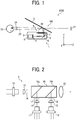
- FIG. 1 is an illustration of the virtual-image forming device 1 according to at least one embodiment of the present disclosure.
- the virtual-image forming device 1 and a transmission and reflection member 2 constitute a heads-up display (HUD) 100.
- HUD heads-up display
- the HUD 100 is installed in a mobile object such as a vehicle, ship, and aircraft.
- the HUD 100 includes, for example, the transmission and reflection member 2, such as a windshield, disposed on each mobile object to transmit and reflect light.
- the HUD 100 allows an observer as a passenger in a vehicle to visually recognize navigation information representing a necessary speed of operating the mobile object, using the transmission and reflection member 2.
- the transmission and reflection member 2 serves as any known windshield that transmits some of incident light and reflects at least some of the remining incident light.
- the virtual-image forming device 1 includes, for example, a device body 3, a real-image plane 4, a real-image forming unit 5, a mirror 6, and a lens element 7.
- the real-image plane 4 is, for example, a diffusing board or a microlens array, onto which a real-image is projected.
- the real-image forming unit 5 forms a real-image to be projected onto the real-image plane 4.
- the real-image plane, the real-image forming unit 5, the mirror 6, and the lens element 7 are disposed within the device body 3.
- the mirror 6 and the lens element 7 constitute an observation optical system 8.
- the device body 3 has an opening 9 above the lens element 7, to allow a real-image of a light beam emitted from the real-image forming unit 5 to exit the device body 3.
- X direction is defined as directions between a front side of the paper and a back side of the paper
- Y direction is defined as up-and-down directions
- Z direction is defined as right and left directions.
- the width direction of the mirror 6 is X direction while X direction is the right and left directions of the mirror 6 when viewed from the front side of the HUD 100.
- a liquid crystal display (LCD) configuration or a digital light processing (DLP) configuration is applicable in the present disclosure.
- FIG. 2 is a schematic view of the real-image forming unit 5 according to an embodiment of the present disclosure.
- the real-image forming unit 5 includes a red light source 10, a green light source 11, and a blue light source 12.
- the real-image forming unit 5 combines three light beams emitted from the light sources 10, 11, and 12 into one light beam (a combined light beam), and scans the real-image plane 4 with the combined light beam using a two-dimensional deflector to form a real-image on the real-image plane 4.
- Each of the light sources 10, 11, and 12 is, for example, a laser diode (LD) as an end-surface emitting laser.
- LD laser diode
- VCSEL surface-emitting laser
- Coupling lenses 13, 14, and 15 correspond to the light sources 10, 11, and 12, respectively.
- the coupling lenses 13, 14, and 15 serve to reduce the divergence of light beams (laser beams) emitted from the light sources 10, 11, and 12, respectively.
- Apertures 16, 17, and 18 restricts the diameters of and shapes the light beams from the light sources 10, 11, and 12, respectively.
- the light beams, of which the divergence has been reduced by the coupling lenses 13, 14, and 15, are restricted and shaped by the apertures 16, 17, and 18, and enter a beam combining prism 19.
- the beam combining prism 19 includes, for example, a first dichroic film 19a and a second dichroic film 19b.
- the first dichroic film 19a serves to transmit a red light beam therethrough and reflect a green light beam.
- the second dichroic film 19b serves to transmit a red light beam and a green light beam therethrough and reflect a blue light beam.
- the beam combining prism 19 emits one light beam, in which a red light beam, a green light beam, and a blue light beam are combined, and the combined light beam of red, green, and blue colors is converted into a collimated light beam having a given diameter by a lens 20.
- the collimated light beam is a pixel displaying beam.
- the intensities of the laser beams of red, green, and blue colors that constitute the pixel displaying beam are modulated according to an image signal (i.e., image data) of a real image that is a "two-dimensional color image" to be displayed.
- the intensity modulation is performed through direct modulation in which the semiconductor lasers are directly modulated or through external modulation in which the laser beams emitted from the semiconductor lasers are modulated.
- the light-emission intensity of each of the light sources 10, 11, and 12 as semiconductor lasers is modulated by a driving unit according to the image signal of a corresponding color component.
- the pixel displaying beam emitted from the lens 20 is directed to a two-dimensional deflector as an image forming element to be two-dimensionally deflected.
- the two-dimensional deflector is a micro mirror that moves on a pivot that is formed by two axes that are orthogonal to each other. More specifically, the two-dimensional deflector is, for example, a micro-electromechanical systems (MEMS) that includes a micro pivoting mirrors formed by, e.g., semiconductor processes.
- MEMS micro-electromechanical systems
- the mirror 6 and the lens element 7 serve to eliminate the distortion of the real-image on the real-image plane 4 caused by the transmission and reflection member 2 while forming a virtual image 21 to virtually display the real-image.
- Examples of the mirror 6 includes any known concave mirror, and examples of the lens element 7 include any known resin lens of cycloolefin polymer resin.
- the observation optical system 8 of the virtual-image forming device 1 serves to enlarge the real-image formed on the real-image plane 4 to form the virtual image 21.
- the device body 3 further includes a cover 25 above the lens element 7 to prevent dust from entering the device body 3.
- the lens mirror 7 disposed above the mirror 6 has positive power, which allows reducing the diameter of the light beam hitting the mirror 6, thereby allowing a reduction in area of the mirror 6.
- FIG. 6 is a schematic view of a configuration of the virtual-image forming device 1 according to an embodiment of the present disclosure.
- a virtual-image forming device 90 includes a device body having a plane for forming a real-image (a real-image forming plane) to emit a light image.
- the emitted light image is reflected by a concave mirror 92 and directed to an observer 94 through an opening 91, thus forming a virtual image 93.
- the observer can visually recognize the virtual image 93 as if the virtual image 93 actually exists.
- FIG. 7 is a conceptual illustration of the virtual-image forming device 1.
- FIG. 7 is an illustration of a virtual-image forming device 96 with a compact device body in which a convex lens 95 having positive power is disposed right in front of a concave mirror 97.
- the size of the opening 91 disposed in the optical path is determined by the virtual-image angle of view (an angle of view of the virtual image 93 relative to an observer 94), the virtual-image distance (the distance from the observer 94 to the virtual image 93), and the viewing area (the range of a field of view of the observer 9). Accordingly, there is no significant change in size of the opening 91 without any change in space in which the virtual-image forming device 96 is disposed and the relative positions of the virtual image 93 and the observer 94.
- the convex lens 95 having positive power is disposed near the opening 91, to reduce the diameter of the light beam hitting the concave mirror 97 so that the concave mirror 97 smaller than the concave mirror 92 in FIG. 6 is used.
- the configuration according to the present embodiment achieves a reduction in size of device.
- the transmission and reflection member 2 is disposed on a front side of the virtual image 21 in Z direction, that is, between the virtual image 21 and the observer 22.
- the transmission and reflection member 2 reflects a light beam for forming the virtual image 21, to the observer 22 side.
- the observer 22 (for example, a passenger in a mobile object) visually recognizes the virtual image 21 at a prescribed position in the optical path of the light beam (laser beam) reflected by the transmission and reflection member 2. Accordingly, the observer 22 visually recognizes the virtual image 21 with the light reflected by the transmission and reflection member 2.
- the transmission and reflection member 2 has a shape with a reflecting surface on the room-interior (vehicle-interior) side having positive power.
- a vertical-directional section (YZ plane) and a horizontal-directional section (ZX plane) of the transmission and reflection member 2 differ in positive power of the reflecting surface such that the power of the vertical-directional section (YZ plane) is greater than the power of the horizontal-directional section (ZX plane).
- the mirror 6 and the lens element 7 are preferably configured to have a shape in which the power of the horizontal-directional section (ZX plane) is greater than the power of a section (the vertical-directional section (YZ plane) orthogonal to the horizontal-directional section (ZX plane)) serving as an optical path to the vertical-directional section (YZ plane) of the transmission and reflection member 2.
- configuring the mirror 6 to have greater power than the lens element 7 does facilitates reducing the light-ray effective range of the mirror 6 and achieving a compact virtual-image forming device 1.
- the real image on the real-image plane 4 is formed by light rays having divergence.
- the divergence of the light rays forming the real image allows illuminating a relatively wide area close to the observer 22's eyes.
- a viewing area 24 When the real image is formed by light rays without divergence, an extremely small area of the observer 22 is illuminated so that the observer 22 fails to visually recognize the virtual image 21 with a slight movement of the head.
- the area to allow the observer 22 to visually recognize the virtual image 21 is referred to as a viewing area 24.
- the position of the head of the observer 22 differs between individuals. Accordingly, the positions of the virtual image 21 and the viewing area 24 are adjusted according to the individual position. To achieve an effective adjustment of the positions, the orientation of the mirror 6 having power is changed by a reflection event.
- the mirror 6 is supported by a supporting member fixed to the device body 3, to be rotatable around an axis perpendicular to the direction of the optical axis of the light beam emitted from the real-image forming unit 5.
- the mirror 6 is supported by the supporting member to be rotatable around the X-axis.
- a single mirror 6 is disposed as an adjustable mirror, and the lens element 7 is disposed below the opening 9 serving as an exit for a light beam.
- This arrangement provides a compact virtual-image forming device 1 that exhibits a maximum performance for correcting aberrations with a minimum configuration.
- the virtual-image forming device 1 When the virtual-image forming device 1 according to the present embodiment is installed in a mobile object, it is difficult to have the position of the eyes of the observer 22 coincide with the position of the virtual-image forming device 1. Further, in many cases, the virtual-image forming device 1 is disposed away from the observer 22 to a certain extent. Thus, it is difficult to obtain the relative positions of the eyes of the observer 22 and the virtual-image forming device 1 with high accuracy.
- an appropriate size of the opening 9 is determined by geometric calculation using the product specification: the angle of view of virtual image, the distance to the virtual image, and the viewing area 24 of the observer 22, irrespective of the size of the virtual-image forming device 1. This means that reduction in size of the device body 3 has little influence on the size of the opening 9.
- the mirror 6 and the lens element 7 share the power to correct aberrations, thereby reducing the length of the optical path between the real-image plane 4 and the mirror 6, which leads to a reduction in space for the mirror 6, thus achieving the reduction in size of the device.
- the principal point of the positive power is allowed to move to the virtual image 21 side, thereby reducing the length of the optical path between the real-image plane 4 and the mirror 6 without a significant change in magnification of the virtual image 21, which allows a reduction in space for the mirror 6, compared to a comparative configuration including the mirror 6 without the lens element 7.
- the lens element 7 includes a single positive lens having positive power, but no limitation is intended thereby.
- the lens element 7 includes a plurality of positive lenses.
- the lens element 7 includes a single set of or a plurality of sets of a plurality of lens elements formed by combining any number of positive lenses and negative lenses having negative power, to have positive power as a whole.
- the lens element 7 includes a negative lens, which allows correcting chromatic aberration, resulting in an increase in visibility of the virtual image 21.
- an optical element such as a diffraction element or a hologram element is arranged as the lens element 7 to exert the same positive power as a whole.
- the lens element 7 is configured to transmit a light beam while having positive power as a whole, which exhibits the above-described advantageous operation and effects.
- FIG. 3 is an illustration of a first cross-sectional surface in a direction of a first angle of view of a virtual image and a second-sectional surface in a direction of a second angle of view of the virtual image smaller than the first angle of view in the lens element 7 according to an embodiment of the present disclosure.
- the first cross-sectional surface is indicated by line A
- the second cross-sectional surface is indicated by line B.
- the first cross-sectional surface is perpendicular to the second cross-sectional surface.
- the first cross-sectional surface has power different from that of the second cross-sectional surface.
- angles of view of the virtual image 21 are not symmetric with respect to a point. In general, the angles of view of the virtual image 21 significantly differ between X direction and Y direction, and the transmission and reflection member 2 has power that differs between directions.
- the lens element 7 has power that differs between the first cross-sectional surface and the second cross-sectional surface, distortion generated is effectively corrected.
- the lens element 7 has each surface having power.
- a virtual-image forming device 1 that increases the visibility of the virtual image 21 while achieving a reduction in size.
- the lens element 7 has at least one surface made of a Fresnel lens.
- a windshield is used as the transmission and reflection member 2. Accordingly, when the direction in which a light beam is emitted from the virtual-image forming device 1 is substantially the vertical direction (Y direction), some light rays are allowed to pass through the transmission and reflection member 2 in the upward direction.
- the cover 25 is disposed above the lens element 7 to prevent dust from entering the device body 3.
- FIG. 4 is an illustration of the virtual-image forming device 1 according to a variation of the above-described embodiment. As illustrated in FIG. 4 , a dustproof lens 26 having a dustproof function is used instead of the lens element 7 and the cover 25.
- the dustproof lens 26 has a lens portion in the center, and has an area other than the lens portion, i.e., an area surrounding the lens portion, tightly close contact with the edge of the opening 9 of the device body 3.
- close contact means that the area other than the lens portion is in contact with the edge of the opening 9 to prevent dust from entering the interior of the device body 3. That is, the entire circumference of the dustproof lens 26 is not fixed to the device body 3.
- FIG. 9 is an illustration of a lens element 29 used in the virtual-image forming device 1 according to a variation of the above-described embodiment of the present disclosure.
- the lens element 29 is used instead of the lens element 7 as illustrated in FIG. 9 .
- the lens element 29 has a concave surface that faces the outside of the virtual-image forming device 1 and serves to allow light emitted from the real-image forming unit 5 to exit the virtual-image forming device 1.
- FIG. 10 is an illustration of a lens element 30 used in the virtual-image forming device 1 according to another variation of the above-described embodiment.
- the lens element 30 having a convex surface (contrary to the lens element 29) that faces the outside of the virtual-image forming device 1 is used.
- FIGs. 9 and 10 represents an angle of view of an unnecessary virtual image of external light, formed by a surface (also referred to as an outer surface) of the lens element 29 (in FIG. 9 ) or the lens element 30 (in FIG. 10 ) that allows light to exit the virtual-image forming device 1.
- Such a phenomenon occurs when the sunlight is reflected by the outer surface of the lens element 29 or 30 and reaches the observer 22 so that the observer 22 observes an unnecessary virtual image of sunlight.
- the lens element 30 has the outer surface of a convex shape, which serves to diverge light rays at an angle of view ⁇ to form an unnecessary virtual image.
- the lens element 29 has the outer surface of a concave shape, which serves to converge light rays at an angle of view ⁇ to form an unnecessary virtual image.
- Such a configuration provided with the lens element 29 reduces the range in which an unnecessary virtual image of external light reaches the observer 22. Accordingly, the visibility of a virtual image by the observer 22 further improves.
- the lens element 7 has positive power.
- the mirror 6 also has positive power. With such a configuration, the mirror 6 and the lens element 7 share positive power while forming a virtual image 21, thereby facilitating correcting aberrations while achieving the reduction in size of device.
- the mirror 6 preferably has power that differs between a first cross-sectional surface in a direction of a first angle of view of a virtual image and a second cross-sectional surface, which is perpendicular to the first cross-sectional surface, in a direction of a second angle of view of the virtual image smaller than the first angle of view.
- This configuration allows increasing the performance of correcting distortion same as the lens element 7.
- the mirror 6 and the lens element 7 correct aberrations by establishing a relative position of the mirror 6 and the lens element 7. Accordingly, with a reduction in manufacturing error due to the assembly or part accuracy, aberrations are successfully corrected.
- FIG. 5 is an illustration of a holding member 27 that holds the mirror 6 and the lens element 7 in the virtual-image forming 1 according to a variation of the above-described embodiment. As illustrated in FIG. 5 , the mirror 6 and the lens element 7 are supported by the same holding member 27. The holding member 27 is attached onto the device body 3, which eliminates or reduces the manufacturing error, thus preventing a deterioration in visibility of the virtual image 21.
- the mirror 6 is attached to the holding member 27 to be rotatable around a support shaft 28 extending in X direction and positioned within the virtual-image forming device 1. This configuration further allows adjusting the positions of the virtual image 21 and the viewing area 24 by adjusting the position of the mirror 6, thereby increasing the mountability of the device to a mobile object.
- the mirror 6 is attached to be rotatable about X direction.
- the mirror 6 is rotatable around an axis tilted with respect to the X direction.
Landscapes
- Physics & Mathematics (AREA)
- General Physics & Mathematics (AREA)
- Optics & Photonics (AREA)
- Lenses (AREA)
Abstract
Description
- Embodiments of the present disclosure relate to a virtual-image forming device and a mobile object.
- A virtual-image forming device has been known as a constituent element of a heads-up display (HUD), configured to cause an image, which is to be displayed on a display panel, to be reflected by a windshield of a vehicle and directed to a passenger.
- Such a virtual-image forming device allows the passenger to recognize a virtual image representing various information.
- Such a virtual-image forming device includes a device body having a plane for forming a real-image to emit a light image. The emitted light image is reflected by a concave mirror and directed to an observer through an opening, thus forming a virtual image. As a result, the observer can visually recognize the virtual image as if the virtual image actually exists.
- In the field of such a virtual-image forming device, the technology has been known that facilitates correcting aberrations and reduces the length of an optical path by disposing a lens element in an observation optical system, thus achieving a reduction in size of the device.
- To achieve such a compact virtual-image forming device, a configuration has been proposed in which an aspherical Fresnel lens is additionally disposed in the downstream of a concave mirror along the optical path, which compensates for a distortion caused by the shape of the windshield to thereby facilitate correcting aberrations and achieve the reduction in size of device (see, for example,
JP-2009-122582-A1 - However, such a comparative device that includes the concave mirror has difficulties in reducing the size of the device because the size of the concave mirror is determined by the distance from an observer to a virtual image, the angle of view of the virtual image relative to the observer, and the field-of-view of the observer, and because the concave mirror occupies a large space in the device body.
- In one aspect of this disclosure, there is provided an improved virtual-image forming device includes a device body having an opening; a real-image forming unit disposed within the device body to output light; a mirror to reflect the light output from the real-image forming unit; and an optical element. The optical element has positive power to refract the light reflected by the mirror and let the light exit the opening to guide the light to a transmission and reflection member to form a virtual image of the light.
- In another aspect of this disclosure there is provided an improved mobile object including the above-described virtual-image forming device and transmission and reflection member.
- The embodiments of the present disclosure achieve a compact virtual-image device while obtaining an appropriate angle of view of a virtual image relative to an observer, an appropriate distance to the virtual image, and an appropriate viewing area of an observer.
- The aforementioned and other aspects, features, and advantages of the present disclosure will be better understood by reference to the following detailed description when considered in connection with the accompanying drawings, wherein:
-
FIG. 1 is a schematic view of a virtual-image forming device according to an embodiment of the present disclosure; -
FIG. 2 is an illustration of a real-image forming unit according to an embodiment of the present disclosure, used in the virtual-image forming device ofFIG. 1 ; -
FIG. 3 is an illustration of a first cross-sectional surface in a direction of a first angle of view of a virtual image and a second cross-sectional surface in a direction of a second angle of view of the virtual image in a lens element used in the virtual-image forming device ofFIG. 1 ; -
FIG. 4 is a schematic view of a virtual-image forming device according to a variation of an embodiment of the present disclosure; -
FIG. 5 is an illustration of a member for holding a mirror and a lens element used in the virtual-image forming device according to a variation of an embodiment of the present disclosure; -
FIG. 6 is a conceptual illustration of a virtual-image forming device according to an embodiment of the present disclosure; -
FIG. 7 is a conceptual illustration of the virtual-image forming device ofFIG. 1 ; -
FIG. 8 is an illustration of technical difficulties involved with a comparative virtual-image forming device; -
FIG. 9 is an illustration of a lens element used in a virtual-image forming device according to a variation of an embodiment of the present disclosure; and -
FIG. 10 is an illustration of a lens element used in a virtual-image forming device according to another variation of an embodiment of the present disclosure. - The accompanying drawings are intended to depict embodiments of the present disclosure and should not be interpreted to limit the scope thereof. The accompanying drawings are not to be considered as drawn to scale unless explicitly noted.
- In describing embodiments illustrated in the drawings, specific terminology is employed for the sake of clarity. However, the disclosure of this patent specification is not intended to be limited to the specific terminology so selected and it is to be understood that each specific element includes all technical equivalents that have the same function, operate in a similar manner, and achieve similar results.
- Although the embodiments are described with technical limitations with reference to the attached drawings, such description is not intended to limit the scope of the disclosure and all of the components or elements described in the embodiments of this disclosure are not necessarily indispensable.
- The present disclosure is not limited to the following embodiments, and the constituent elements of the embodiments include those which can be easily conceived by those skilled in the art, substantially the same ones, and those in the following embodiments include those which can be easily conceived by those skilled in the art, substantially the same, and within equivalent ranges. Furthermore, various omissions, substitutions, changes and combinations of constituent elements can be made without departing from the gist of the following embodiments.
- In a
HUD 80 according to a comparative example as illustrated inFIG. 8 for explaining the technical difficulties involved with thecomparative HUD 80, there is a need to virtually display areal image 82 formed on a display within adevice body 81, as a virtual image 83 at a long distance. - In such a configuration according to the comparative example, an observation
optical system 85 is further disposed to virtually display thereal image 82 through awindshield 84 of a vehicle. - The observation
optical system 85 defines an angle of view of a virtual image (virtual-image angle of view) relative to anobserver 86, a distance from theobserver 86 to the virtual image (virtual-image distance), and a range of field of view of (viewing area) theobserver 86. The observationoptical system 85 occupies a relatively large space of thedevice body 81, which might hamper reducing the size of the HUD. - As an example of the observation
optical system 85, aconcave mirror 87 is used in many cases to efficiently adjust the position of a virtual image corresponding to the position of theobserver 86. - The size of the
concave mirror 87 is determined by the virtual-image distance, the virtual-image angle of view, and the viewing area of theobserver 86. Theconcave mirror 87 occupies a large volume in the observationoptical system 85. In addition to theconcave mirror 87, the optical path from the real-image 82 to theconcave mirror 87 also occupies a large volume in the observationoptical system 85. - The optical path can be reduced by the technology that facilitates correcting aberrations and reduces the length of an optical path by disposing a lens element in an observation optical system. However, a reduction in size of the
concave mirror 87 is difficult because the size of anopening 88 of thedevice body 81 is substantially determined by, for example, the width of a light beam emitted from thedevice body 81 for virtually displaying the real-image 82. - In view of such circumstances, the present inventors have conceived of the following embodiments of the present disclosure.
- A detailed description is given below of a virtual-image forming device 1 referring to the drawings.
-
FIG. 1 is an illustration of the virtual-image forming device 1 according to at least one embodiment of the present disclosure. - As illustrated in
FIG. 1 , the virtual-image forming device 1 and a transmission andreflection member 2 constitute a heads-up display (HUD) 100. - The HUD 100 is installed in a mobile object such as a vehicle, ship, and aircraft. The
HUD 100 includes, for example, the transmission andreflection member 2, such as a windshield, disposed on each mobile object to transmit and reflect light. TheHUD 100 allows an observer as a passenger in a vehicle to visually recognize navigation information representing a necessary speed of operating the mobile object, using the transmission andreflection member 2. - The transmission and
reflection member 2 serves as any known windshield that transmits some of incident light and reflects at least some of the remining incident light. - The virtual-image forming device 1 includes, for example, a
device body 3, a real-image plane 4, a real-image forming unit 5, amirror 6, and alens element 7. The real-image plane 4 is, for example, a diffusing board or a microlens array, onto which a real-image is projected. The real-image forming unit 5 forms a real-image to be projected onto the real-image plane 4. The real-image plane, the real-image forming unit 5, themirror 6, and thelens element 7 are disposed within thedevice body 3. - The
mirror 6 and thelens element 7 constitute an observationoptical system 8. Thedevice body 3 has anopening 9 above thelens element 7, to allow a real-image of a light beam emitted from the real-image forming unit 5 to exit thedevice body 3. - In
FIG. 1 , X direction is defined as directions between a front side of the paper and a back side of the paper, Y direction is defined as up-and-down directions, and Z direction is defined as right and left directions. The same applies to the other figures. For example, the width direction of themirror 6 is X direction while X direction is the right and left directions of themirror 6 when viewed from the front side of theHUD 100. - Hereinafter, a description is given of a laser scanning configuration of the real-
image plane 4 and the real-image forming unit 5. However, alternatively, in some embodiments, a liquid crystal display (LCD) configuration or a digital light processing (DLP) configuration is applicable in the present disclosure. -
FIG. 2 is a schematic view of the real-image forming unit 5 according to an embodiment of the present disclosure. As illustrated inFIG. 2 , the real-image forming unit 5 includes ared light source 10, agreen light source 11, and a bluelight source 12. The real-image forming unit 5 combines three light beams emitted from thelight sources image plane 4 with the combined light beam using a two-dimensional deflector to form a real-image on the real-image plane 4. - Each of the
light sources light sources - Coupling
lenses light sources coupling lenses light sources -
Apertures light sources coupling lenses apertures beam combining prism 19. - The
beam combining prism 19 includes, for example, a firstdichroic film 19a and a seconddichroic film 19b. The firstdichroic film 19a serves to transmit a red light beam therethrough and reflect a green light beam. The seconddichroic film 19b serves to transmit a red light beam and a green light beam therethrough and reflect a blue light beam. - Accordingly, the
beam combining prism 19 emits one light beam, in which a red light beam, a green light beam, and a blue light beam are combined, and the combined light beam of red, green, and blue colors is converted into a collimated light beam having a given diameter by alens 20. The collimated light beam is a pixel displaying beam. - Note that the intensities of the laser beams of red, green, and blue colors that constitute the pixel displaying beam are modulated according to an image signal (i.e., image data) of a real image that is a "two-dimensional color image" to be displayed.
- The intensity modulation is performed through direct modulation in which the semiconductor lasers are directly modulated or through external modulation in which the laser beams emitted from the semiconductor lasers are modulated.
In other words, the light-emission intensity of each of thelight sources - The pixel displaying beam emitted from the
lens 20 is directed to a two-dimensional deflector as an image forming element to be two-dimensionally deflected. - In the present example embodiment, the two-dimensional deflector is a micro mirror that moves on a pivot that is formed by two axes that are orthogonal to each other. More specifically, the two-dimensional deflector is, for example, a micro-electromechanical systems (MEMS) that includes a micro pivoting mirrors formed by, e.g., semiconductor processes.
- The
mirror 6 and thelens element 7 serve to eliminate the distortion of the real-image on the real-image plane 4 caused by the transmission andreflection member 2 while forming avirtual image 21 to virtually display the real-image. - Examples of the
mirror 6 includes any known concave mirror, and examples of thelens element 7 include any known resin lens of cycloolefin polymer resin.
The observationoptical system 8 of the virtual-image forming device 1 serves to enlarge the real-image formed on the real-image plane 4 to form thevirtual image 21. Thedevice body 3 further includes acover 25 above thelens element 7 to prevent dust from entering thedevice body 3. - The
lens mirror 7 disposed above themirror 6 has positive power, which allows reducing the diameter of the light beam hitting themirror 6, thereby allowing a reduction in area of themirror 6. -
FIG. 6 is a schematic view of a configuration of the virtual-image forming device 1 according to an embodiment of the present disclosure. InFIG. 6 , a virtual-image forming device 90 includes a device body having a plane for forming a real-image (a real-image forming plane) to emit a light image. The emitted light image is reflected by aconcave mirror 92 and directed to anobserver 94 through anopening 91, thus forming avirtual image 93. As a result, the observer can visually recognize thevirtual image 93 as if thevirtual image 93 actually exists. In contrast,FIG. 7 is a conceptual illustration of the virtual-image forming device 1.FIG. 7 is an illustration of a virtual-image forming device 96 with a compact device body in which aconvex lens 95 having positive power is disposed right in front of aconcave mirror 97. - The size of the
opening 91 disposed in the optical path is determined by the virtual-image angle of view (an angle of view of thevirtual image 93 relative to an observer 94), the virtual-image distance (the distance from theobserver 94 to the virtual image 93), and the viewing area (the range of a field of view of the observer 9). Accordingly, there is no significant change in size of theopening 91 without any change in space in which the virtual-image forming device 96 is disposed and the relative positions of thevirtual image 93 and theobserver 94. - For this reason, in the virtual-
image forming device 96 according to the present embodiment, theconvex lens 95 having positive power is disposed near theopening 91, to reduce the diameter of the light beam hitting theconcave mirror 97 so that theconcave mirror 97 smaller than theconcave mirror 92 inFIG. 6 is used. The configuration according to the present embodiment achieves a reduction in size of device. - Referring back to
FIG. 1 , the transmission andreflection member 2 is disposed on a front side of thevirtual image 21 in Z direction, that is, between thevirtual image 21 and theobserver 22. The transmission andreflection member 2 reflects a light beam for forming thevirtual image 21, to theobserver 22 side. - The observer 22 (for example, a passenger in a mobile object) visually recognizes the
virtual image 21 at a prescribed position in the optical path of the light beam (laser beam) reflected by the transmission andreflection member 2.
Accordingly, theobserver 22 visually recognizes thevirtual image 21 with the light reflected by the transmission andreflection member 2. - When the relation of shape between the transmission and
reflection member 2, themirror 6 and thelens element 7 is established, a successful visual recognition is provided. - With such a configuration, at each of angles of view of the virtual image that are two axes perpendicular to each other of the
mirror 6 and thelens element 7, avirtual image 21 with little distortion is formed by the light beam passed through themirror 6, thelens element 7, and the transmission andreflection member 2. - For example, the transmission and
reflection member 2 has a shape with a reflecting surface on the room-interior (vehicle-interior) side having positive power. In this case, it is assumed that a vertical-directional section (YZ plane) and a horizontal-directional section (ZX plane) of the transmission andreflection member 2 differ in positive power of the reflecting surface such that the power of the vertical-directional section (YZ plane) is greater than the power of the horizontal-directional section (ZX plane). - In this case, the
mirror 6 and thelens element 7 are preferably configured to have a shape in which the power of the horizontal-directional section (ZX plane) is greater than the power of a section (the vertical-directional section (YZ plane) orthogonal to the horizontal-directional section (ZX plane)) serving as an optical path to the vertical-directional section (YZ plane) of the transmission andreflection member 2. Thus, distortion of a virtual image is successfully corrected. - Further, configuring the
mirror 6 to have greater power than thelens element 7 does facilitates reducing the light-ray effective range of themirror 6 and achieving a compact virtual-image forming device 1. - The real image on the real-
image plane 4 is formed by light rays having divergence. The divergence of the light rays forming the real image allows illuminating a relatively wide area close to theobserver 22's eyes. - When the real image is formed by light rays without divergence, an extremely small area of the
observer 22 is illuminated so that theobserver 22 fails to visually recognize thevirtual image 21 with a slight movement of the head. The area to allow theobserver 22 to visually recognize thevirtual image 21 is referred to as aviewing area 24. - The position of the head of the
observer 22 differs between individuals. Accordingly, the positions of thevirtual image 21 and theviewing area 24 are adjusted according to the individual position. To achieve an effective adjustment of the positions, the orientation of themirror 6 having power is changed by a reflection event. - More specifically, the
mirror 6 is supported by a supporting member fixed to thedevice body 3, to be rotatable around an axis perpendicular to the direction of the optical axis of the light beam emitted from the real-image forming unit 5. For example, themirror 6 is supported by the supporting member to be rotatable around the X-axis. - In the virtual-image forming device 1 according to the present embodiment, a
single mirror 6 is disposed as an adjustable mirror, and thelens element 7 is disposed below theopening 9 serving as an exit for a light beam. This arrangement provides a compact virtual-image forming device 1 that exhibits a maximum performance for correcting aberrations with a minimum configuration. - When the virtual-image forming device 1 according to the present embodiment is installed in a mobile object, it is difficult to have the position of the eyes of the
observer 22 coincide with the position of the virtual-image forming device 1. Further, in many cases, the virtual-image forming device 1 is disposed away from theobserver 22 to a certain extent. Thus, it is difficult to obtain the relative positions of the eyes of theobserver 22 and the virtual-image forming device 1 with high accuracy. - To obtain stable visibility even in such a case, setting the
viewing area 24 that sufficiently covers the range of the eyes of theobserver 22 and adjusting the position of theviewing area 24 are important factors. - In the configuration according to the present embodiment, an appropriate size of the
opening 9 is determined by geometric calculation using the product specification: the angle of view of virtual image, the distance to the virtual image, and theviewing area 24 of theobserver 22, irrespective of the size of the virtual-image forming device 1. This means that reduction in size of thedevice body 3 has little influence on the size of theopening 9. - As described above, by disposing the
lens element 7 closer to thevirtual image 21 than themirror 6, that is, by arranging thelens element 7 at a position closer to theopening 9 than themirror 6, an increase in size of the entire device is sufficiently prevented even when thelens element 7 has the same size as that of theopening 9. - Further, the
mirror 6 and thelens element 7 share the power to correct aberrations, thereby reducing the length of the optical path between the real-image plane 4 and themirror 6, which leads to a reduction in space for themirror 6, thus achieving the reduction in size of the device. - In this configuration, for example, the principal point of the positive power is allowed to move to the
virtual image 21 side, thereby reducing the length of the optical path between the real-image plane 4 and themirror 6 without a significant change in magnification of thevirtual image 21, which allows a reduction in space for themirror 6, compared to a comparative configuration including themirror 6 without thelens element 7. - Note that, in the configuration according to the present embodiment, the
lens element 7 includes a single positive lens having positive power, but no limitation is intended thereby. Thus, alternatively, in some embodiments, thelens element 7 includes a plurality of positive lenses. Alternatively, in some other embodiments, thelens element 7 includes a single set of or a plurality of sets of a plurality of lens elements formed by combining any number of positive lenses and negative lenses having negative power, to have positive power as a whole. In this case, thelens element 7 includes a negative lens, which allows correcting chromatic aberration, resulting in an increase in visibility of thevirtual image 21. - In some embodiments, an optical element such as a diffraction element or a hologram element is arranged as the
lens element 7 to exert the same positive power as a whole. - Such a configuration allows for a thinner or smaller element than a lens element having the same function, thus achieving a reduction in device as a whole.
Thus, thelens element 7 is configured to transmit a light beam while having positive power as a whole, which exhibits the above-described advantageous operation and effects. -
FIG. 3 is an illustration of a first cross-sectional surface in a direction of a first angle of view of a virtual image and a second-sectional surface in a direction of a second angle of view of the virtual image smaller than the first angle of view in thelens element 7 according to an embodiment of the present disclosure. InFIG. 3 , the first cross-sectional surface is indicated by line A, and the second cross-sectional surface is indicated by line B. The first cross-sectional surface is perpendicular to the second cross-sectional surface. The first cross-sectional surface has power different from that of the second cross-sectional surface. - The angles of view of the
virtual image 21 are not symmetric with respect to a point. In general, the angles of view of thevirtual image 21 significantly differ between X direction and Y direction, and the transmission andreflection member 2 has power that differs between directions. - With the configuration in which the
lens element 7 has power that differs between the first cross-sectional surface and the second cross-sectional surface, distortion generated is effectively corrected. - Preferably, in the present embodiment, the
lens element 7 has each surface having power. - With such a configuration, the number of surfaces that correct aberrations increases, and the performance of correcting aberrations improves. Thus, a virtual-image forming device 1 is provided that increases the visibility of the
virtual image 21 while achieving a reduction in size. - Preferably, in the present embodiment, the
lens element 7 has at least one surface made of a Fresnel lens. - With this configuration, the size in the height direction of the
lens element 7 is reduced and the virtual image forming apparatus 1 is further miniaturized. - In the present disclosure, a windshield is used as the transmission and
reflection member 2. Accordingly, when the direction in which a light beam is emitted from the virtual-image forming device 1 is substantially the vertical direction (Y direction), some light rays are allowed to pass through the transmission andreflection member 2 in the upward direction. - In an automobile for example, if light passes through the windshield at an approximately horizontal angle, i.e., at an angle close to the angle of Z direction, the oncoming vehicle and surrounding pedestrians might be dazzled. However, with the configuration that allows the light to pass through the windshield in the upward direction, i.e., at an angle close to the angle of Y direction, the possibility that the transmitted light harms the surrounding pedestrian and outcoming vehicle is reduced and safety is increased.
- In the above-described embodiment, the
cover 25 is disposed above thelens element 7 to prevent dust from entering thedevice body 3. -
FIG. 4 is an illustration of the virtual-image forming device 1 according to a variation of the above-described embodiment. As illustrated inFIG. 4 , adustproof lens 26 having a dustproof function is used instead of thelens element 7 and thecover 25. - The
dustproof lens 26 has a lens portion in the center, and has an area other than the lens portion, i.e., an area surrounding the lens portion, tightly close contact with the edge of theopening 9 of thedevice body 3. - Note that the expression "close contact" means that the area other than the lens portion is in contact with the edge of the
opening 9 to prevent dust from entering the interior of thedevice body 3. That is, the entire circumference of thedustproof lens 26 is not fixed to thedevice body 3. - With this configuration, there is no need to dispose the
cover 25 in thedevice body 3, which achieves a reduction in cost and a reduction in the size of the device. -
FIG. 9 is an illustration of alens element 29 used in the virtual-image forming device 1 according to a variation of the above-described embodiment of the present disclosure. In the virtual-image forming device 1 according to a variation of the present embodiment, thelens element 29 is used instead of thelens element 7 as illustrated inFIG. 9 . Thelens element 29 has a concave surface that faces the outside of the virtual-image forming device 1 and serves to allow light emitted from the real-image forming unit 5 to exit the virtual-image forming device 1. -
FIG. 10 is an illustration of alens element 30 used in the virtual-image forming device 1 according to another variation of the above-described embodiment. In the virtual-image forming device 1 inFIG. 10 , thelens element 30 having a convex surface (contrary to the lens element 29) that faces the outside of the virtual-image forming device 1 is used.
Each ofFIGs. 9 and 10 represents an angle of view of an unnecessary virtual image of external light, formed by a surface (also referred to as an outer surface) of the lens element 29 (inFIG. 9 ) or the lens element 30 (inFIG. 10 ) that allows light to exit the virtual-image forming device 1. - Such a phenomenon occurs when the sunlight is reflected by the outer surface of the
lens element observer 22 so that theobserver 22 observes an unnecessary virtual image of sunlight. - The
lens element 30 has the outer surface of a convex shape, which serves to diverge light rays at an angle of view β to form an unnecessary virtual image.
In contrast, thelens element 29 has the outer surface of a concave shape, which serves to converge light rays at an angle of view α to form an unnecessary virtual image. - Such a configuration provided with the
lens element 29 reduces the range in which an unnecessary virtual image of external light reaches theobserver 22. Accordingly, the visibility of a virtual image by theobserver 22 further improves. - In the present variation, the case in which the
lens element 29 is used is described. However, no limitation is intended thereby. Thus, alternatively, in some examples, a dustproof lens configured in the same manner as thedustproof lens 26 is used instead of thelens element 29. - In the present embodiment, the
lens element 7 has positive power.
In some embodiments, themirror 6 also has positive power.
With such a configuration, themirror 6 and thelens element 7 share positive power while forming avirtual image 21, thereby facilitating correcting aberrations while achieving the reduction in size of device. - Same as the
lens element 7, themirror 6 preferably has power that differs between a first cross-sectional surface in a direction of a first angle of view of a virtual image and a second cross-sectional surface, which is perpendicular to the first cross-sectional surface, in a direction of a second angle of view of the virtual image smaller than the first angle of view.
This configuration allows increasing the performance of correcting distortion same as thelens element 7. - In the above-described virtual image forming apparatus 1, the
mirror 6 and thelens element 7 correct aberrations by establishing a relative position of themirror 6 and thelens element 7. Accordingly, with a reduction in manufacturing error due to the assembly or part accuracy, aberrations are successfully corrected. -
FIG. 5 is an illustration of a holdingmember 27 that holds themirror 6 and thelens element 7 in the virtual-image forming 1 according to a variation of the above-described embodiment. As illustrated inFIG. 5 , themirror 6 and thelens element 7 are supported by the same holdingmember 27. The holdingmember 27 is attached onto thedevice body 3, which eliminates or reduces the manufacturing error, thus preventing a deterioration in visibility of thevirtual image 21. - Note that the
mirror 6 is attached to the holdingmember 27 to be rotatable around asupport shaft 28 extending in X direction and positioned within the virtual-image forming device 1.
This configuration further allows adjusting the positions of thevirtual image 21 and theviewing area 24 by adjusting the position of themirror 6, thereby increasing the mountability of the device to a mobile object. - In the above-described embodiment, the
mirror 6 is attached to be rotatable about X direction. However, alternatively, in some embodiments, themirror 6 is rotatable around an axis tilted with respect to the X direction. - Numerous additional modifications and variations are possible in light of the above teachings. It is therefore to be understood that within the scope of the appended claims, the embodiments may be practiced otherwise than as specifically described herein. For example, elements and/or features of different illustrative embodiments may be combined with each other and/or substituted for each other within the scope of this disclosure and appended claims.
Claims (15)
- A virtual-image forming device (1) comprising:a device body (3) having an opening (9);a real-image forming unit (5) disposed within the device body (3) to output light; anda mirror (6) to reflect the light output from the real-image forming unit (5);an optical element (7) having positive power to refract the light reflected by the mirror (6) and let the light exit through the opening (9) to guide the light to a transmission and reflection member (2) to form a virtual image of the light.
- The virtual-image forming device (1) according to claim 1,
wherein the optical element (7) has power that differs between a first cross-sectional surface and a second cross-sectional surface perpendicular to the first cross-sectional surface. - The virtual-image forming device (1) according to claim 1 or 2,
wherein the optical element (7) has two surfaces and each of the two surfaces has power. - The virtual-image forming device (1) according to any of claims 1 through 3,
wherein the optical element (7) has at least one surface made of a Fresnel lens. - The virtual-image forming device (1) according to any of claims 1 through 4,
wherein the light exits through the opening (9) in a direction substantially vertical to the opening (9). - The virtual-image forming device (1) according to any of claims 1 through 5,
wherein the optical element (7) is disposed on the device body (3) to seal the opening (9). - The virtual-image forming device (1) according to any of claims 1 through 6,
wherein the optical element (7) has a concave surface to output the light. - The virtual-image forming device (1) according to any of claims 1 through 7,
wherein the mirror (6) has positive power. - The virtual-image forming device (1) according to any of claims 1 through 8,
wherein the mirror (6) has power that differs between a first cross-sectional surface and a second cross-sectional surface perpendicular to the first cross-sectional surface. - The virtual-image forming device (1) according to any of claims 1 through 9,
wherein the mirror (6) and the optical element (7) are positioned by a common member in the device body (3). - The virtual-image forming device (1) according to any of claims 1 through 10,
wherein the mirror (6) forms a variable angle relative to the optical element (7). - The virtual-image forming device (1) according to any of claims 1 through 11,
wherein the optical element (7) includes a plurality of lenses. - The virtual-image forming device (1) according to claim 12,
wherein the plurality of lenses includes a negative lens. - The virtual-image forming device (1) according to any of claims 1 through 13,
wherein the optical element (7) includes one of a diffractive element and a hologram element. - A mobile object (1000) comprising:the virtual-image forming device (1) according to any of claims 1 through 14; andthe transmission and reflection member (2).
Applications Claiming Priority (2)
| Application Number | Priority Date | Filing Date | Title |
|---|---|---|---|
| JP2017097388 | 2017-05-16 | ||
| JP2018043286A JP2018194820A (en) | 2017-05-16 | 2018-03-09 | Virtual image forming apparatus and moving body |
Publications (2)
| Publication Number | Publication Date |
|---|---|
| EP3404468A2 true EP3404468A2 (en) | 2018-11-21 |
| EP3404468A3 EP3404468A3 (en) | 2019-02-20 |
Family
ID=62089677
Family Applications (1)
| Application Number | Title | Priority Date | Filing Date |
|---|---|---|---|
| EP18169928.1A Withdrawn EP3404468A3 (en) | 2017-05-16 | 2018-04-27 | Virtual-image forming device and mobile object |
Country Status (2)
| Country | Link |
|---|---|
| US (1) | US10775620B2 (en) |
| EP (1) | EP3404468A3 (en) |
Families Citing this family (3)
| Publication number | Priority date | Publication date | Assignee | Title |
|---|---|---|---|---|
| US12099207B2 (en) | 2019-03-20 | 2024-09-24 | Ricoh Company, Ltd. | Virtual image display device |
| CN118151404A (en) * | 2024-05-10 | 2024-06-07 | 成都工业学院 | A three-dimensional transparent display device |
| GB202418756D0 (en) * | 2024-12-19 | 2025-02-05 | Envisics Ltd | Corrective device for disparity control |
Citations (1)
| Publication number | Priority date | Publication date | Assignee | Title |
|---|---|---|---|---|
| JP2009122582A (en) | 2007-11-19 | 2009-06-04 | Fujinon Corp | Projection optical system and head-up display apparatus |
Family Cites Families (52)
| Publication number | Priority date | Publication date | Assignee | Title |
|---|---|---|---|---|
| US4632508A (en) | 1984-08-01 | 1986-12-30 | Grumman Aerospace Corporation | Windscreen deviation correcting pilot display |
| GB8822731D0 (en) * | 1988-09-28 | 1988-11-02 | Secr Defence | Head-up display |
| US6259565B1 (en) * | 1996-11-19 | 2001-07-10 | Sony Corporation | Display apparatus |
| JP4355134B2 (en) | 2002-10-09 | 2009-10-28 | 矢崎総業株式会社 | Vehicle display device |
| JP4417700B2 (en) | 2003-09-19 | 2010-02-17 | 株式会社リコー | Lighting device |
| JP2005202145A (en) * | 2004-01-15 | 2005-07-28 | Olympus Corp | On-vehicle head-up display, vehicle having the same, and manufacturing method of vehicle having the same |
| DE102005012011A1 (en) * | 2005-03-16 | 2006-09-28 | Carl Zeiss Jena Gmbh | Projection unit for a head-up display |
| JP2007065528A (en) * | 2005-09-02 | 2007-03-15 | Konica Minolta Photo Imaging Inc | Magnification optical system and imaging device |
| DE102008015997B4 (en) * | 2007-03-29 | 2015-09-10 | Denso Corporation | Head-Up Display |
| JP4886751B2 (en) | 2008-09-25 | 2012-02-29 | 株式会社東芝 | In-vehicle display system and display method |
| JP5515723B2 (en) | 2009-02-02 | 2014-06-11 | 株式会社リコー | Optical scanning apparatus, image forming apparatus, and optical communication system |
| CN101900869B (en) | 2009-05-25 | 2012-10-03 | 株式会社理光 | Image forming lens, camera device, and handheld terminal |
| JP5568923B2 (en) | 2009-08-25 | 2014-08-13 | 株式会社リコー | Imaging optical system, camera device, and portable information terminal device |
| JP5370109B2 (en) | 2009-12-02 | 2013-12-18 | 株式会社リコー | Imaging lens and imaging apparatus |
| JP5505617B2 (en) | 2009-12-10 | 2014-05-28 | 株式会社リコー | Optical scanning apparatus and image forming apparatus |
| EP2397880B1 (en) | 2010-06-16 | 2017-04-12 | Ricoh Company, Ltd. | Image-forming lens, and camera device and portable information terminal device with the image-forming lens |
| JP5494961B2 (en) | 2010-06-17 | 2014-05-21 | 株式会社リコー | Optical scanning apparatus and image forming apparatus |
| US8780463B2 (en) | 2010-06-24 | 2014-07-15 | Ricoh Company, Ltd. | Image-forming lens, and imaging apparatus and information device using the image-forming lens |
| JP5622099B2 (en) | 2010-12-13 | 2014-11-12 | 株式会社リコー | Imaging lens, imaging device, and information device |
| JP5605211B2 (en) | 2010-12-20 | 2014-10-15 | 株式会社リコー | Projection optical system and image projection apparatus |
| JP5621583B2 (en) | 2010-12-27 | 2014-11-12 | 株式会社リコー | Projection optical system and image projection apparatus |
| JP2013061554A (en) | 2011-09-14 | 2013-04-04 | Ricoh Co Ltd | Image forming apparatus, and vehicle with image forming apparatus mounted thereon |
| US8950874B2 (en) | 2011-09-16 | 2015-02-10 | Ricoh Company, Ltd. | Projection optical system and image display apparatus |
| JP5919724B2 (en) * | 2011-10-20 | 2016-05-18 | 日本精機株式会社 | Head-up display device for vehicle |
| JP5825047B2 (en) | 2011-10-28 | 2015-12-02 | 株式会社リコー | Image display device |
| JP5935131B2 (en) | 2011-10-31 | 2016-06-15 | 株式会社リコー | Image display device |
| JP5849613B2 (en) | 2011-10-31 | 2016-01-27 | 株式会社リコー | Image display device |
| US9703081B2 (en) | 2012-05-15 | 2017-07-11 | Ricoh Company, Ltd. | Projection zoom lens and projector |
| JP6011168B2 (en) | 2012-09-03 | 2016-10-19 | 株式会社リコー | Projection zoom lens and projector apparatus |
| US9158119B2 (en) | 2012-10-31 | 2015-10-13 | Ricoh Company, Ltd. | Enlargement optical system |
| US8922883B2 (en) | 2012-11-05 | 2014-12-30 | Ricoh Company, Ltd. | Magnification optical system |
| JP6090650B2 (en) | 2012-11-19 | 2017-03-08 | 株式会社リコー | Imaging lens, imaging device, and information device |
| JP6172431B2 (en) | 2012-11-26 | 2017-08-02 | 株式会社リコー | Projection optical system |
| JP6025048B2 (en) | 2012-12-27 | 2016-11-16 | 株式会社リコー | Imaging optical system, camera device, and portable information terminal device |
| US9664883B2 (en) | 2012-12-28 | 2017-05-30 | Ricoh Company, Ltd. | Image display device |
| US9638903B2 (en) | 2012-12-28 | 2017-05-02 | Ricoh Company, Ltd. | Projection zoom lens |
| JP6236811B2 (en) | 2013-03-14 | 2017-11-29 | 株式会社リコー | Light source unit, illumination device, and image projection device |
| JP6368988B2 (en) | 2013-05-20 | 2018-08-08 | 株式会社リコー | Projection optical system and image display device |
| JP6361115B2 (en) | 2013-11-15 | 2018-07-25 | 株式会社リコー | Projection lens and image display device |
| US10078217B2 (en) * | 2014-10-24 | 2018-09-18 | Ricoh Company, Ltd. | Image display device and apparatus |
| JP6617945B2 (en) | 2015-03-11 | 2019-12-11 | 株式会社リコー | Image display device |
| US9746652B2 (en) | 2015-06-10 | 2017-08-29 | Ricoh Company, Ltd. | Projection lens and image display device |
| JP2017016006A (en) | 2015-07-03 | 2017-01-19 | 株式会社リコー | Optical scanning device, image display device |
| JP6578785B2 (en) | 2015-07-24 | 2019-09-25 | 株式会社リコー | Imaging optical system, camera device, and portable information terminal device |
| WO2017022176A1 (en) * | 2015-08-06 | 2017-02-09 | パナソニックIpマネジメント株式会社 | Head-up display and moving body equipped with head-up display |
| JP2017044870A (en) | 2015-08-26 | 2017-03-02 | 株式会社リコー | Image display device, image display unit |
| JP6604090B2 (en) | 2015-08-27 | 2019-11-13 | 株式会社リコー | Projection optical system, projection apparatus and projection system |
| US10088620B2 (en) | 2015-09-29 | 2018-10-02 | Ricoh Company, Ltd. | Light guide, virtual image optical system, and virtual image display device |
| JP6672746B2 (en) | 2015-11-27 | 2020-03-25 | 株式会社リコー | Image display device and vehicle |
| EP3190447B1 (en) | 2016-01-06 | 2020-02-05 | Ricoh Company, Ltd. | Light guide and virtual image display device |
| JP6658351B2 (en) | 2016-06-29 | 2020-03-04 | 株式会社リコー | Image display device and head-up display system |
| JP6963732B2 (en) * | 2016-09-30 | 2021-11-10 | 日本精機株式会社 | Head-up display device |
-
2018
- 2018-04-26 US US15/963,365 patent/US10775620B2/en not_active Expired - Fee Related
- 2018-04-27 EP EP18169928.1A patent/EP3404468A3/en not_active Withdrawn
Patent Citations (1)
| Publication number | Priority date | Publication date | Assignee | Title |
|---|---|---|---|---|
| JP2009122582A (en) | 2007-11-19 | 2009-06-04 | Fujinon Corp | Projection optical system and head-up display apparatus |
Also Published As
| Publication number | Publication date |
|---|---|
| EP3404468A3 (en) | 2019-02-20 |
| US10775620B2 (en) | 2020-09-15 |
| US20180335624A1 (en) | 2018-11-22 |
Similar Documents
| Publication | Publication Date | Title |
|---|---|---|
| EP3447561B1 (en) | Head-up display device | |
| JP5517992B2 (en) | Scanning projector | |
| JP6207850B2 (en) | Virtual image display device | |
| EP3012681B1 (en) | Image display device and apparatus | |
| US10942352B2 (en) | Head-up display apparatus | |
| US20170285338A1 (en) | Vehicular projection display apparatus | |
| JP7715889B2 (en) | Head-up display | |
| EP3469414B1 (en) | Image display apparatus | |
| KR102087800B1 (en) | Virtual display | |
| JP7531145B2 (en) | Head-up display | |
| US11061228B2 (en) | Head-up display for automobile | |
| US10775620B2 (en) | Virtual-image forming device and mobile object | |
| WO2017138431A1 (en) | Display device and head-up display | |
| US11567314B2 (en) | Image display apparatus and mobile apparatus | |
| JP2007094394A (en) | Optical system for head-up display | |
| EP3006988B1 (en) | Image display apparatus | |
| JP2018010138A (en) | Display, projection device, and movable body including display or projection device | |
| KR20240153999A (en) | Wavefront manipulator with total reflection and reflection holograms | |
| JP2018180291A (en) | Vehicle display device | |
| CN113835283B (en) | Projection display system and forming method thereof | |
| JP6611310B2 (en) | Projection display device for vehicle | |
| JP2018194820A (en) | Virtual image forming apparatus and moving body | |
| EP3789227B1 (en) | Vehicle display device | |
| KR20190042318A (en) | Head-up display device | |
| GB2619794A (en) | Retinal scanning display device |
Legal Events
| Date | Code | Title | Description |
|---|---|---|---|
| PUAI | Public reference made under article 153(3) epc to a published international application that has entered the european phase |
Free format text: ORIGINAL CODE: 0009012 |
|
| STAA | Information on the status of an ep patent application or granted ep patent |
Free format text: STATUS: REQUEST FOR EXAMINATION WAS MADE |
|
| 17P | Request for examination filed |
Effective date: 20180427 |
|
| AK | Designated contracting states |
Kind code of ref document: A2 Designated state(s): AL AT BE BG CH CY CZ DE DK EE ES FI FR GB GR HR HU IE IS IT LI LT LU LV MC MK MT NL NO PL PT RO RS SE SI SK SM TR |
|
| AX | Request for extension of the european patent |
Extension state: BA ME |
|
| PUAL | Search report despatched |
Free format text: ORIGINAL CODE: 0009013 |
|
| AK | Designated contracting states |
Kind code of ref document: A3 Designated state(s): AL AT BE BG CH CY CZ DE DK EE ES FI FR GB GR HR HU IE IS IT LI LT LU LV MC MK MT NL NO PL PT RO RS SE SI SK SM TR |
|
| AX | Request for extension of the european patent |
Extension state: BA ME |
|
| RIC1 | Information provided on ipc code assigned before grant |
Ipc: G02B 27/01 20060101AFI20190114BHEP Ipc: G02B 3/08 20060101ALI20190114BHEP Ipc: G02B 27/00 20060101ALI20190114BHEP |
|
| STAA | Information on the status of an ep patent application or granted ep patent |
Free format text: STATUS: EXAMINATION IS IN PROGRESS |
|
| 17Q | First examination report despatched |
Effective date: 20210913 |
|
| STAA | Information on the status of an ep patent application or granted ep patent |
Free format text: STATUS: THE APPLICATION HAS BEEN WITHDRAWN |
|
| 18W | Application withdrawn |
Effective date: 20211008 |