EP3404376A1 - Electrical connection having a gold contact surface with discrete areas of hardness and fuel level sensor using the same - Google Patents
Electrical connection having a gold contact surface with discrete areas of hardness and fuel level sensor using the same Download PDFInfo
- Publication number
- EP3404376A1 EP3404376A1 EP18172773.6A EP18172773A EP3404376A1 EP 3404376 A1 EP3404376 A1 EP 3404376A1 EP 18172773 A EP18172773 A EP 18172773A EP 3404376 A1 EP3404376 A1 EP 3404376A1
- Authority
- EP
- European Patent Office
- Prior art keywords
- gold
- electrical conductor
- area
- conductor surface
- electrical
- Prior art date
- Legal status (The legal status is an assumption and is not a legal conclusion. Google has not performed a legal analysis and makes no representation as to the accuracy of the status listed.)
- Withdrawn
Links
Images



Classifications
-
- G—PHYSICS
- G01—MEASURING; TESTING
- G01F—MEASURING VOLUME, VOLUME FLOW, MASS FLOW OR LIQUID LEVEL; METERING BY VOLUME
- G01F23/00—Indicating or measuring liquid level or level of fluent solid material, e.g. indicating in terms of volume or indicating by means of an alarm
- G01F23/30—Indicating or measuring liquid level or level of fluent solid material, e.g. indicating in terms of volume or indicating by means of an alarm by floats
- G01F23/32—Indicating or measuring liquid level or level of fluent solid material, e.g. indicating in terms of volume or indicating by means of an alarm by floats using rotatable arms or other pivotable transmission elements
- G01F23/36—Indicating or measuring liquid level or level of fluent solid material, e.g. indicating in terms of volume or indicating by means of an alarm by floats using rotatable arms or other pivotable transmission elements using electrically actuated indicating means
-
- G—PHYSICS
- G01—MEASURING; TESTING
- G01F—MEASURING VOLUME, VOLUME FLOW, MASS FLOW OR LIQUID LEVEL; METERING BY VOLUME
- G01F23/00—Indicating or measuring liquid level or level of fluent solid material, e.g. indicating in terms of volume or indicating by means of an alarm
- G01F23/30—Indicating or measuring liquid level or level of fluent solid material, e.g. indicating in terms of volume or indicating by means of an alarm by floats
- G01F23/32—Indicating or measuring liquid level or level of fluent solid material, e.g. indicating in terms of volume or indicating by means of an alarm by floats using rotatable arms or other pivotable transmission elements
- G01F23/36—Indicating or measuring liquid level or level of fluent solid material, e.g. indicating in terms of volume or indicating by means of an alarm by floats using rotatable arms or other pivotable transmission elements using electrically actuated indicating means
- G01F23/363—Indicating or measuring liquid level or level of fluent solid material, e.g. indicating in terms of volume or indicating by means of an alarm by floats using rotatable arms or other pivotable transmission elements using electrically actuated indicating means using electromechanically actuated indicating means
-
- G—PHYSICS
- G01—MEASURING; TESTING
- G01D—MEASURING NOT SPECIALLY ADAPTED FOR A SPECIFIC VARIABLE; ARRANGEMENTS FOR MEASURING TWO OR MORE VARIABLES NOT COVERED IN A SINGLE OTHER SUBCLASS; TARIFF METERING APPARATUS; MEASURING OR TESTING NOT OTHERWISE PROVIDED FOR
- G01D5/00—Mechanical means for transferring the output of a sensing member; Means for converting the output of a sensing member to another variable where the form or nature of the sensing member does not constrain the means for converting; Transducers not specially adapted for a specific variable
- G01D5/12—Mechanical means for transferring the output of a sensing member; Means for converting the output of a sensing member to another variable where the form or nature of the sensing member does not constrain the means for converting; Transducers not specially adapted for a specific variable using electric or magnetic means
- G01D5/14—Mechanical means for transferring the output of a sensing member; Means for converting the output of a sensing member to another variable where the form or nature of the sensing member does not constrain the means for converting; Transducers not specially adapted for a specific variable using electric or magnetic means influencing the magnitude of a current or voltage
- G01D5/16—Mechanical means for transferring the output of a sensing member; Means for converting the output of a sensing member to another variable where the form or nature of the sensing member does not constrain the means for converting; Transducers not specially adapted for a specific variable using electric or magnetic means influencing the magnitude of a current or voltage by varying resistance
- G01D5/165—Mechanical means for transferring the output of a sensing member; Means for converting the output of a sensing member to another variable where the form or nature of the sensing member does not constrain the means for converting; Transducers not specially adapted for a specific variable using electric or magnetic means influencing the magnitude of a current or voltage by varying resistance by relative movement of a point of contact or actuation and a resistive track
-
- G—PHYSICS
- G01—MEASURING; TESTING
- G01F—MEASURING VOLUME, VOLUME FLOW, MASS FLOW OR LIQUID LEVEL; METERING BY VOLUME
- G01F23/00—Indicating or measuring liquid level or level of fluent solid material, e.g. indicating in terms of volume or indicating by means of an alarm
- G01F23/30—Indicating or measuring liquid level or level of fluent solid material, e.g. indicating in terms of volume or indicating by means of an alarm by floats
- G01F23/32—Indicating or measuring liquid level or level of fluent solid material, e.g. indicating in terms of volume or indicating by means of an alarm by floats using rotatable arms or other pivotable transmission elements
-
- G—PHYSICS
- G01—MEASURING; TESTING
- G01F—MEASURING VOLUME, VOLUME FLOW, MASS FLOW OR LIQUID LEVEL; METERING BY VOLUME
- G01F23/00—Indicating or measuring liquid level or level of fluent solid material, e.g. indicating in terms of volume or indicating by means of an alarm
- G01F23/30—Indicating or measuring liquid level or level of fluent solid material, e.g. indicating in terms of volume or indicating by means of an alarm by floats
- G01F23/76—Indicating or measuring liquid level or level of fluent solid material, e.g. indicating in terms of volume or indicating by means of an alarm by floats characterised by the construction of the float
-
- H—ELECTRICITY
- H01—ELECTRIC ELEMENTS
- H01C—RESISTORS
- H01C10/00—Adjustable resistors
- H01C10/30—Adjustable resistors the contact sliding along resistive element
- H01C10/32—Adjustable resistors the contact sliding along resistive element the contact moving in an arcuate path
-
- H—ELECTRICITY
- H01—ELECTRIC ELEMENTS
- H01R—ELECTRICALLY-CONDUCTIVE CONNECTIONS; STRUCTURAL ASSOCIATIONS OF A PLURALITY OF MUTUALLY-INSULATED ELECTRICAL CONNECTING ELEMENTS; COUPLING DEVICES; CURRENT COLLECTORS
- H01R12/00—Structural associations of a plurality of mutually-insulated electrical connecting elements, specially adapted for printed circuits, e.g. printed circuit boards [PCB], flat or ribbon cables, or like generally planar structures, e.g. terminal strips, terminal blocks; Coupling devices specially adapted for printed circuits, flat or ribbon cables, or like generally planar structures; Terminals specially adapted for contact with, or insertion into, printed circuits, flat or ribbon cables, or like generally planar structures
- H01R12/70—Coupling devices
- H01R12/71—Coupling devices for rigid printing circuits or like structures
- H01R12/712—Coupling devices for rigid printing circuits or like structures co-operating with the surface of the printed circuit or with a coupling device exclusively provided on the surface of the printed circuit
- H01R12/714—Coupling devices for rigid printing circuits or like structures co-operating with the surface of the printed circuit or with a coupling device exclusively provided on the surface of the printed circuit with contacts abutting directly the printed circuit; Button contacts therefore provided on the printed circuit
-
- H—ELECTRICITY
- H01—ELECTRIC ELEMENTS
- H01R—ELECTRICALLY-CONDUCTIVE CONNECTIONS; STRUCTURAL ASSOCIATIONS OF A PLURALITY OF MUTUALLY-INSULATED ELECTRICAL CONNECTING ELEMENTS; COUPLING DEVICES; CURRENT COLLECTORS
- H01R35/00—Flexible or turnable line connectors, i.e. the rotation angle being limited
- H01R35/04—Turnable line connectors with limited rotation angle with frictional contact members
-
- H—ELECTRICITY
- H01—ELECTRIC ELEMENTS
- H01R—ELECTRICALLY-CONDUCTIVE CONNECTIONS; STRUCTURAL ASSOCIATIONS OF A PLURALITY OF MUTUALLY-INSULATED ELECTRICAL CONNECTING ELEMENTS; COUPLING DEVICES; CURRENT COLLECTORS
- H01R4/00—Electrically-conductive connections between two or more conductive members in direct contact, i.e. touching one another; Means for effecting or maintaining such contact; Electrically-conductive connections having two or more spaced connecting locations for conductors and using contact members penetrating insulation
- H01R4/58—Electrically-conductive connections between two or more conductive members in direct contact, i.e. touching one another; Means for effecting or maintaining such contact; Electrically-conductive connections having two or more spaced connecting locations for conductors and using contact members penetrating insulation characterised by the form or material of the contacting members
- H01R4/62—Connections between conductors of different materials; Connections between or with aluminium or steel-core aluminium conductors
Definitions
- the present invention relates an electrical connection; more particularly to an electrical connection having a first electrical conductor with a first electrical conductor surface which mates with a second electrical conductor surface of a second electrical conductor; even more particularly to such an electrical connection where the second electrical conductor surface has a first area of gold having a first hardness and a second area of gold having a second hardness; and still even more particularly to a fuel level sensor which includes such an electrical connection.
- Fuel tanks which hold a volume of fuel, for example gasoline or diesel fuel, to be supplied to an internal combustion engine of a motor vehicle are known to include a fuel level sensor which generates a signal indicative of the fuel level within the fuel tank. The signal is provided to a fuel level gauge which delivers a visual display to an operator of the motor vehicle to keep the operator informed of the quantity of fuel remaining in the fuel tank.
- a fuel level sensor includes a ceramic card with a resistive circuit disposed thereon and also includes a wiper assembly which makes sliding contact with the resistive circuit. The wiper assembly is attached to a float which changes the position of the wiper assembly on the resistive circuit.
- the wiper assembly includes a soft gold contact surface which engages the resistive circuit which is silver-based. While this arrangement limits gold, which is relatively expensive, to the wiper assembly, soft gold may have a shorter service life than is desirable.
- the wiper assembly includes a hard gold contact surface which engages the resistive circuit. While the hard gold contact surface increases the durability of the wiper assembly, the service life of the silver-based resistive circuit may be shorter than is desirable due to the hard gold with which the silver-based resistive circuit interfaces.
- the resistive circuit when a hard gold contact surface is used on the wiper assembly, it is typical for the resistive circuit to be gold-based in order to provide an acceptable service life since the gold-on-gold sliding interaction is more durable than the gold-on-silver sliding interaction. While fuel level sensors which include a wiper assembly having a hard gold contact surface and a gold-based resistive circuit on the ceramic card provide a satisfactory service life, the cost of such an arrangement may be prohibitive to implement because of the increased amount of gold in the fuel level sensor.
- an electrical connection includes a first electrical conductor assembly having a first electrical conductor with a first electrical conductor surface and a second electrical conductor assembly having a second electrical conductor with a second electrical conductor surface which is engaged with the first electrical conductor surface such that the second electrical conductor assembly and the first electrical conductor assembly reciprocate relative to each other along a path, the first electrical conductor surface and the second electrical conductor surface thereby providing electrical communication between the first electrical conductor assembly and the second electrical conductor assembly along the path.
- the second electrical conductor surface has a first area of gold having a first magnitude of hardness which engages the first electrical conductor surface and also has a second area of gold having a second magnitude of hardness which is greater than the first magnitude of hardness.
- the second electrical conductor assembly may be included in a fuel level sensor.
- the second electrical conductor surface having areas of gold with discrete magnitudes of harness allows for the softer areas of gold to deposit on the first electrical conductor surface while the harder areas of gold provide where resistance for the second electrical conductor assembly. Furthermore, since the softer gold becomes deposited on the first electrical conductor surface as the softer gold wears, the first electrical conductor surface can be formed free of gold, thereby allowing the electrical connection to be formed more economically.
- reciprocation of the second electrical conductor assembly relative to the first electrical conductor assembly causes the first area of gold and the second area of gold to pass over a common area of the first electrical conductor surface.
- the first area of gold may have a Knoop hardness in the range of 60-85 HkN and the second area of gold may have a Knoop hardness in the range of 120-300 HkN.
- the path is centered about an axis and the second electrical conductor surface may have a width which traverses the axis and a length which may be perpendicular to the width.
- the first area of gold may extend uninterrupted for the width for a portion of the length.
- the second area of gold may extend uninterrupted for the width for another portion of the length.
- the first area of gold may be circumferentially surrounded by the second area of gold.
- the first area of gold may be one of a plurality of first areas of gold, each of said plurality of first areas of gold has said first magnitude of hardness; each of said plurality of first areas of gold may engage the first electrical conductor surface and each of said plurality of first areas of gold may be individually circumferentially surrounded by said second area of gold.
- the second area of gold may be circumferentially surrounded by the first area of gold.
- the second area of gold may be one of a plurality of second areas of gold, each of said plurality of second areas of gold has said second magnitude of hardness.
- Each of said plurality of second areas of gold may engage said first electrical conductor surface.
- Each of said plurality of second areas of gold may be individually circumferentially surrounded by said first area of gold.
- the electrical connection may further comprise a resistor card upon which the first electrical conductor is disposed and a float responsive to fuel level within a fuel tank, the second electrical conductor assembly may be reciprocated along said path by said float responding to the fuel level within the fuel tank.
- the first area of gold may have a Knoop hardness in the range of 60-85 HkN and the second area of gold may have a Knoop hardness in the range of 120-300 HkN.
- the path is centered about an axis and the second electrical conductor surface may have a width which traverses the axis and a length which is perpendicular to the width.
- the first area of gold may extend uninterrupted for said width for a portion of said length.
- the second area of gold may extend uninterrupted for said width for another portion of the length.
- the first area of gold may be circumferentially surrounded by the second area of gold.
- the first area of gold may be one of a plurality of first areas of gold, and each of the plurality of first areas of gold may have said first magnitude of hardness.
- Each of said plurality of first areas of gold may engage said first electrical conductor surface and each of said plurality of first areas of gold may be individually circumferentially surrounded by said second area of gold.
- the second area of gold may be circumferentially surrounded by said first area of gold.
- the second area of gold may be one of a plurality of second areas of gold and each of said plurality of second areas of gold may have said second magnitude of hardness.
- Each of said plurality of second areas of gold may engage the first electrical conductor surface and each of said plurality of second areas of gold may be individually circumferentially surrounded by said first area of gold.
- the electrical connection may further comprise a resistor card upon which the first electrical conductor may be disposed, and a float responsive to fuel level within a fuel tank.
- the second electrical conductor assembly may be reciprocated along the path by the float responding to the fuel level within the fuel tank.
- a fuel level sensor comprises a resistor card upon which a first electrical conductor may be disposed, said first electrical conductor having a first electrical conductor surface, a wiper assembly upon which a second electrical conductor is disposed, said second electrical conductor having a second electrical conductor surface which is engaged with said first electrical conductor surface such that said first electrical conductor surface and said second electrical conductor surface provide electrical communication between said resistor card and said wiper assembly and a float responsive to fuel level within a fuel tank such that said wiper assembly is reciprocated by said float in response to the fuel level within said fuel tank such that said second electrical conductor surface reciprocates along a path on said first electrical conductor surface wherein said second electrical conductor surface has a first area of gold having a first magnitude of hardness which engages said first electrical conductor surface and also has a second area of gold having a second magnitude of hardness which is greater than said first magnitude of hardness.
- a fuel level sensor 10 is shown for a fuel tank 12 (partially shown) of a vehicle (not shown).
- the fuel tank 12 includes a fuel pump module 14 therein with a removable cover 16 sealed to the top of fuel tank 12 with an electrical connector 18 and a fuel line outlet connector 20.
- Fuel pump module 14 includes a fuel reservoir 22 that contains an electrical fuel pump 24 with an inlet 26 and fuel level sensor 10 to indicate fuel level in the fuel tank 12.
- fuel level sensor 10 includes a housing 28 having a recess 30 therein for carrying a resistor card 32. Housing 28 also has a recess or hole 34 therein for a hollow male portion 36 of a wiper assembly 38.
- Wiper assembly 38 is pivotally connected to housing 28 with the aid of a bushing 40, which extends through hollow male portion 36.
- Wiper assembly 38 includes a body portion 42 from which hollow male portion 36 extends, an upper head portion 44 and a lower leg portion 46.
- Upper head portion 44 carries a contact assembly 48 including a first arm 50 and a second arm 52 which are spaced apart and parallel and which are connected together by a bridge 53.
- First arm 50 has a first set of fingers 54, identified individually as fingers 58, 59, 60, which are spaced apart and parallel to each other and extend outwardly from first arm 50.
- second arm 52 has a second set of fingers 56, identified individually as fingers 62, 63, 64, which are spaced apart and parallel to each other and extend outwardly from second arm 52. Both sets of fingers 54, 56 are positioned to travel in an arc-shaped path consistent with a resistive path 96 or a conductive path 84 on the ceramic card as will be described hereafter.
- a float 66 is provided for vertical movement in fuel tank 12 and a lever 68 extends therefrom for engagement in bushing 40.
- Lever 68 extending from float 66 includes a head portion 70, which extends into a hole 72 in bushing 40, and a downwardly extending body portion 74, which is captured, by prongs 76 extending outwardly from lower leg portion 46 of wiper assembly 38.
- lever 68 extending therefrom causes wiper assembly 38 to rotate.
- Resistor card 32 includes a first contact pad 78 having a first wire 80 connected thereto to provide current to first contact pad 78.
- a conductive line 82 extends along one edge of the resistive card from first contact pad 78 to conductive path 84 which is arc-shaped.
- Conductive path 84 includes a base portion 86 which is arc-shaped and continuously solid and a plurality of spaced apart conductor lines 88 extending therefrom at an angle with respect to a radial line drawn from the center of the base portion's 86 arc.
- a second contact pad 90 is provided having a second wire 92 secured thereto.
- a conductive line 94 extends along an opposite side of resistor card 32 from second contact pad 90 to resistive path 96 which is arc-shaped.
- Resistive path 96 includes a resistive ink pattern 98, which is arc-shaped, overlying a plurality of spaced apart conductor lines 100 formed at a radial line drawn from the center of the resistive ink pattern's 98 arc.
- a plurality of small contact pads 102 extends from selective conductor lines 100 of resistive path 96 for purposes of laser trimming resistive path 96.
- first set of fingers 54 on first arm 50 engage conductor lines 100 of resistive path 96 and second set of fingers 64 on second arm 52 engage conductor lines 88 of conductive path 84 which is arc-shaped.
- a top finger 58, 62 of first arm 50 and second arm 52 respectively will engage one of the conductor lines 108, 110 ( Fig. 3 ) and a third finger 60, 64 (parallel to the first finger) on the same arm will contact an adjacent conductor line 112, 114 ( Fig. 3 ) respectively.
- the contact arm is simultaneously contacting adjacent conductor lines thus minimizing or eliminating any problem associated with make brake contact of some known resistor cards.
- first wire 80 to the first contact pad 78 and flows therefrom to conductive path 84 printed on resistor card 32.
- Second set of fingers 56 on second arm 52 of contact assembly 48 engage at least two of the conductor lines 110, 114 on conductive path 84.
- the current then flows across the contact assembly 48 through first arm 50 and first set of fingers 54 to at least two conductor lines 108, 112 on resistive path 96.
- float 66 moves with the fuel level, and wiper assembly 38 rotates along conductive path 84 and resistive path 96. Consequently, a variable resistance to current is provided dependent upon where the contact assembly 48 engages resistive path 96.
- conductive path 84 and resistive path 96 to respective fingers 58, 59, 60, 62, 63, 64 may each be substantially the same, conductive path 84 and resistive path 96 will be generically referred to as first electrical conductor 116 and each finger 58, 59, 60, 62, 63, 64 will be generically referred to as second electrical conductor 118.
- resistor card 32 may be viewed generically as a first electrical conductor assembly having first electrical conductor 116 and wiper assembly 38 may be viewed generically as a second electrical conductor assembly having second electrical conductor 118.
- First electrical conductor 116 includes a first electrical conductor surface 116a while second electrical conductor 118 includes a second electrical conductor surface 118a such that second electrical conductor surface 118a is engaged with first electrical conductor surface 116a, thereby providing electrical communication between the first electrical conductor assembly, i.e. resistor card 32, and the second electrical conductor assembly, i.e. wiper assembly 38.
- path 120 and axis 122 are arcuate in shape, however, other implementations may result in path 120 and axis 122 being linear or some other shape.
- second electrical conductor surface 118a includes a first area of gold 124 having a first magnitude of hardness and also includes a second area of gold 126 having a second magnitude of hardness which is greater than the first magnitude of hardness of first area of gold 124. It should be noted that first area of gold 124 and second area of gold 126 are not visible in Figs. 1-4 . As used herein, first area of gold 124 and second area of gold 126 are each elemental gold or alloys thereof where gold makes up at least 50% of the alloy by weight.
- First area of gold 124 is preferably soft gold with a Knoop hardness in the range of 60-85 HkN and second area of gold 126 is preferably hard gold with a Knoop hardness in the range of 120-300 HkN. Furthermore, second area of gold 126 may be a gold alloy comprising 99.7%-99.9% gold with small amounts of nickel and/or cobalt to achieve the desired harness.
- Second electrical conductor surface 118a has a width W 118a which traverses axis 122 and a length L 118a which is perpendicular to width W 118a . As illustrated in Fig.
- first area of gold 124 extends uninterrupted for width W 118a for a portion of length L 118a while second area of gold 126 extends uninterrupted for width W 118a for the remainder of length L 118a .
- Fig. 7 illustrates a variation to Fig. 6 where first area of gold 124 is divided into a plurality of bands and second are of gold 126 is divided into a plurality of bands such that the bands are arranged in an alternating pattern of bands of first area of gold 124 and second area of gold 126.
- Other patterns of first area of gold 124 and second area of gold 126 are also possible, for example, a checkerboard pattern of first area of gold 124 and second area of gold 126.
- first electrical conductor assembly and the second electrical conductor assembly reciprocation of the first electrical conductor assembly and the second electrical conductor assembly relative to each other results in first area of gold 124 and second area of gold 126 passing over a common area of first electrical conductor surface 116a.
- Repeated reciprocation of the first electrical conductor assembly and the second electrical conductor assembly relative to each other over time causes first area of gold 124 to wear more rapidly than second area of gold 126, due to the differences in hardness, thereby depositing a protective layer of gold from first area of gold 124 on first electrical conductor surface 116a which protects first electrical conductor surface 116a.
- first electrical conductor 116 and second electrical conductor 118 are provided with a long service life without the need to produce first electrical conductor surface 116a with gold.
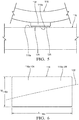
- gold wires may be rolled onto a substrate 128 (only visible in Fig. 5 ), which may be by way of non-limiting example only a nickel-based substrate, thereby shaping the wires into first area of gold 124 and second area of gold 126 and bonding first area of gold 124 and second area of gold 126 to substrate 128.
- a first gold wire (not shown) having the desired hardness of first area of gold 124 and a second gold wire (not shown) having the desired harness of second area of gold 126 are rolled onto substrate 128 under a compressive force, thereby shaping the wires to form first area of gold 124 and second area of gold 126 and also thereby bonding the first area of gold 124 and second area of gold 126 to substrate 128.
- Substrate 128 may then be bonded to second electrical conductor 118, by way of non-limiting example only, by welding.
- first area of gold 124 and second area of gold 126 are provided in an alternative manner. More specifically, with respect to Fig. 8 , a plurality of first areas of gold 124 are provided where each first area of gold 124 is individually circumferentially surrounded by second area of gold 126. For clarity, only some first areas of gold 124 have been labeled in the figure.
- This arrangement may be produced by starting with second area of gold 126 which is free of first areas of gold 124 and topologically applying first areas of gold 124, for example in the form of gold flakes, nodules, or powder, to second area of gold 126 and applying pressure to first areas of gold 124, for example by rolling, to embed first areas of gold 124 into second area of gold 126. While first areas of gold 124 have been illustrated as being placed random in nature, a regular pattern of first areas of gold 124 is also contemplated. In an alternative method of production, first areas of gold 124 may be blended with second area of gold 126.
- first areas of gold 124 are not merely topologically applied, but some portions of first areas of gold 124 may be completely encapsulated within second area of gold 126, but may become exposed with wear of second electrical conductor surface 118a.
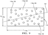
- Fig. 9 is similar to Fig. 8 , except that the positions of first area of gold 124 and second area of gold 126 have been reversed. Consequently, second areas of gold 126 are each individually circumferentially surrounded by first area of gold 124.
- the arrangements of Figs. 8 and 9 provide the same benefit that the arrangements of Figs.
- first electrical conductor 116 and second electrical conductor 118 provide, namely, reciprocation of the first electrical conductor assembly and the second electrical conductor assembly relative to each other results in the first area(s) of gold 124 and the second area(s) of gold 126 passing over a common area of first electrical conductor surface 116a.
- Repeated reciprocation of the first electrical conductor assembly and the second electrical conductor assembly relative to each other over time causes first area(s) of gold 124 to wear more rapidly than second area(s) of gold 126, due to the differences in hardness, thereby depositing a protective layer of gold from first area(s) of gold 124 on first electrical conductor surface 116a which protects first electrical conductor surface 116a.
- first electrical conductor 116 and second electrical conductor 118 are provided with a long service life without the need to produce first electrical conductor surface 116a with gold.
Landscapes
- Physics & Mathematics (AREA)
- General Physics & Mathematics (AREA)
- Fluid Mechanics (AREA)
- Engineering & Computer Science (AREA)
- Microelectronics & Electronic Packaging (AREA)
- Level Indicators Using A Float (AREA)
Abstract
Description
- The present invention relates an electrical connection; more particularly to an electrical connection having a first electrical conductor with a first electrical conductor surface which mates with a second electrical conductor surface of a second electrical conductor; even more particularly to such an electrical connection where the second electrical conductor surface has a first area of gold having a first hardness and a second area of gold having a second hardness; and still even more particularly to a fuel level sensor which includes such an electrical connection.
- Fuel tanks which hold a volume of fuel, for example gasoline or diesel fuel, to be supplied to an internal combustion engine of a motor vehicle are known to include a fuel level sensor which generates a signal indicative of the fuel level within the fuel tank. The signal is provided to a fuel level gauge which delivers a visual display to an operator of the motor vehicle to keep the operator informed of the quantity of fuel remaining in the fuel tank. One known fuel level sensor includes a ceramic card with a resistive circuit disposed thereon and also includes a wiper assembly which makes sliding contact with the resistive circuit. The wiper assembly is attached to a float which changes the position of the wiper assembly on the resistive circuit. Consequently, when an electric current is applied to an input side of the wiper assembly, the signal resulting at an output side of the wiper assembly will vary depending on the position of the wiper assembly relative to the resistive circuit. One such fuel level sensor is illustrated in United States Patent No.
6,681,628 to Sawert et al. - The sliding interface between the resistive circuit and the wiper assembly, and the harsh environment within which the fuel level sensor is located, present challenges in durability. Consequently, precious metals are commonly used to survive the harsh environment and provide good electrical contact. In one known arrangement, the wiper assembly includes a soft gold contact surface which engages the resistive circuit which is silver-based. While this arrangement limits gold, which is relatively expensive, to the wiper assembly, soft gold may have a shorter service life than is desirable. In another known arrangement, the wiper assembly includes a hard gold contact surface which engages the resistive circuit. While the hard gold contact surface increases the durability of the wiper assembly, the service life of the silver-based resistive circuit may be shorter than is desirable due to the hard gold with which the silver-based resistive circuit interfaces. Consequently, when a hard gold contact surface is used on the wiper assembly, it is typical for the resistive circuit to be gold-based in order to provide an acceptable service life since the gold-on-gold sliding interaction is more durable than the gold-on-silver sliding interaction. While fuel level sensors which include a wiper assembly having a hard gold contact surface and a gold-based resistive circuit on the ceramic card provide a satisfactory service life, the cost of such an arrangement may be prohibitive to implement because of the increased amount of gold in the fuel level sensor.
- What is needed is an electrical connection and a fuel level sensor which minimizes or eliminates one or more of the shortcomings as set forth above.
- Briefly described, an electrical connection includes a first electrical conductor assembly having a first electrical conductor with a first electrical conductor surface and a second electrical conductor assembly having a second electrical conductor with a second electrical conductor surface which is engaged with the first electrical conductor surface such that the second electrical conductor assembly and the first electrical conductor assembly reciprocate relative to each other along a path, the first electrical conductor surface and the second electrical conductor surface thereby providing electrical communication between the first electrical conductor assembly and the second electrical conductor assembly along the path. The second electrical conductor surface has a first area of gold having a first magnitude of hardness which engages the first electrical conductor surface and also has a second area of gold having a second magnitude of hardness which is greater than the first magnitude of hardness. The second electrical conductor assembly may be included in a fuel level sensor. The second electrical conductor surface having areas of gold with discrete magnitudes of harness allows for the softer areas of gold to deposit on the first electrical conductor surface while the harder areas of gold provide where resistance for the second electrical conductor assembly. Furthermore, since the softer gold becomes deposited on the first electrical conductor surface as the softer gold wears, the first electrical conductor surface can be formed free of gold, thereby allowing the electrical connection to be formed more economically.
- In the electrical connection, reciprocation of the second electrical conductor assembly relative to the first electrical conductor assembly causes the first area of gold and the second area of gold to pass over a common area of the first electrical conductor surface.
- In the electrical connection the first area of gold may have a Knoop hardness in the range of 60-85 HkN and the second area of gold may have a Knoop hardness in the range of 120-300 HkN.
- In the electrical connection the path is centered about an axis and the second electrical conductor surface may have a width which traverses the axis and a length which may be perpendicular to the width.
- The first area of gold may extend uninterrupted for the width for a portion of the length.
- The second area of gold may extend uninterrupted for the width for another portion of the length.
- In the electrical connection the first area of gold may be circumferentially surrounded by the second area of gold.
- In the electrical connection the first area of gold may be one of a plurality of first areas of gold, each of said plurality of first areas of gold has said first magnitude of hardness; each of said plurality of first areas of gold may engage the first electrical conductor surface and each of said plurality of first areas of gold may be individually circumferentially surrounded by said second area of gold.
- In the electrical connection the second area of gold may be circumferentially surrounded by the first area of gold.
- In the electrical connection the second area of gold may be one of a plurality of second areas of gold, each of said plurality of second areas of gold has said second magnitude of hardness. Each of said plurality of second areas of gold may engage said first electrical conductor surface. Each of said plurality of second areas of gold may be individually circumferentially surrounded by said first area of gold.
- The electrical connection may further comprise a resistor card upon which the first electrical conductor is disposed and a float responsive to fuel level within a fuel tank, the second electrical conductor assembly may be reciprocated along said path by said float responding to the fuel level within the fuel tank.
- In the electrical connection the first area of gold may have a Knoop hardness in the range of 60-85 HkN and the second area of gold may have a Knoop hardness in the range of 120-300 HkN. In the electrical connection the path is centered about an axis and the second electrical conductor surface may have a width which traverses the axis and a length which is perpendicular to the width. The first area of gold may extend uninterrupted for said width for a portion of said length. The second area of gold may extend uninterrupted for said width for another portion of the length.
- In the electrical connection the first area of gold may be circumferentially surrounded by the second area of gold.
- In the electrical connection the first area of gold may be one of a plurality of first areas of gold, and each of the plurality of first areas of gold may have said first magnitude of hardness. Each of said plurality of first areas of gold may engage said first electrical conductor surface and each of said plurality of first areas of gold may be individually circumferentially surrounded by said second area of gold.
- In the electrical connection the second area of gold may be circumferentially surrounded by said first area of gold.
- In the electrical connection the second area of gold may be one of a plurality of second areas of gold and each of said plurality of second areas of gold may have said second magnitude of hardness.
- Each of said plurality of second areas of gold may engage the first electrical conductor surface and each of said plurality of second areas of gold may be individually circumferentially surrounded by said first area of gold.
- The electrical connection may further comprise a resistor card upon which the first electrical conductor may be disposed, and a float responsive to fuel level within a fuel tank. The second electrical conductor assembly may be reciprocated along the path by the float responding to the fuel level within the fuel tank.
- According to another aspect of the invention, a fuel level sensor comprises a resistor card upon which a first electrical conductor may be disposed, said first electrical conductor having a first electrical conductor surface, a wiper assembly upon which a second electrical conductor is disposed, said second electrical conductor having a second electrical conductor surface which is engaged with said first electrical conductor surface such that said first electrical conductor surface and said second electrical conductor surface provide electrical communication between said resistor card and said wiper assembly and a float responsive to fuel level within a fuel tank such that said wiper assembly is reciprocated by said float in response to the fuel level within said fuel tank such that said second electrical conductor surface reciprocates along a path on said first electrical conductor surface wherein said second electrical conductor surface has a first area of gold having a first magnitude of hardness which engages said first electrical conductor surface and also has a second area of gold having a second magnitude of hardness which is greater than said first magnitude of hardness.
- This invention will be further described with reference to the accompanying drawings in which:
-
Fig. 1 an elevation view of a fuel module which incorporates the present invention; -
Fig. 2 is an exploded isometric view of a fuel level sensor of the fuel module ofFig. 1 ; -
Fig. 3 is a face-on view of a resistor card of the fuel level sensor ofFig. 2 ; -
Fig. 4 . is an isometric view of a portion of the resistor card ofFig. 3 together with a wiper assembly of the fuel level sensor ofFig. 2 ; -
Fig. 5 is an elevation view which enlarges a portion of the resistor card and wiper assembly ofFig. 4 ; and -
Figs. 6-9 are face-on views of an electrical conductor surface of the wiper assembly. - Referring to the drawings, and initially in particular
Fig. 1 which illustrates an implementation of the present invention, afuel level sensor 10 is shown for a fuel tank 12 (partially shown) of a vehicle (not shown). Thefuel tank 12 includes afuel pump module 14 therein with aremovable cover 16 sealed to the top offuel tank 12 with anelectrical connector 18 and a fuelline outlet connector 20.Fuel pump module 14 includes afuel reservoir 22 that contains anelectrical fuel pump 24 with aninlet 26 andfuel level sensor 10 to indicate fuel level in thefuel tank 12. - With continued reference to
Fig. 1 , but now with emphasis onFigs. 2-4 ,fuel level sensor 10 includes ahousing 28 having arecess 30 therein for carrying aresistor card 32.Housing 28 also has a recess orhole 34 therein for a hollowmale portion 36 of awiper assembly 38.Wiper assembly 38 is pivotally connected tohousing 28 with the aid of a bushing 40, which extends through hollowmale portion 36.Wiper assembly 38 includes abody portion 42 from which hollowmale portion 36 extends, anupper head portion 44 and alower leg portion 46.Upper head portion 44 carries acontact assembly 48 including afirst arm 50 and asecond arm 52 which are spaced apart and parallel and which are connected together by abridge 53.First arm 50 has a first set offingers 54, identified individually asfingers first arm 50. Similarly,second arm 52 has a second set offingers 56, identified individually asfingers second arm 52. Both sets offingers resistive path 96 or aconductive path 84 on the ceramic card as will be described hereafter. - A
float 66 is provided for vertical movement infuel tank 12 and alever 68 extends therefrom for engagement inbushing 40.Lever 68 extending fromfloat 66 includes ahead portion 70, which extends into ahole 72 inbushing 40, and a downwardly extendingbody portion 74, which is captured, byprongs 76 extending outwardly fromlower leg portion 46 ofwiper assembly 38. Asfloat 66 moves up and down due to the changes in fuel level,lever 68 extending therefromcauses wiper assembly 38 to rotate. -
Resistor card 32 includes afirst contact pad 78 having afirst wire 80 connected thereto to provide current tofirst contact pad 78. Aconductive line 82 extends along one edge of the resistive card fromfirst contact pad 78 toconductive path 84 which is arc-shaped.Conductive path 84 includes abase portion 86 which is arc-shaped and continuously solid and a plurality of spaced apartconductor lines 88 extending therefrom at an angle with respect to a radial line drawn from the center of the base portion's 86 arc. Asecond contact pad 90 is provided having asecond wire 92 secured thereto. Aconductive line 94 extends along an opposite side ofresistor card 32 fromsecond contact pad 90 toresistive path 96 which is arc-shaped.Resistive path 96 includes aresistive ink pattern 98, which is arc-shaped, overlying a plurality of spaced apartconductor lines 100 formed at a radial line drawn from the center of the resistive ink pattern's 98 arc. A plurality ofsmall contact pads 102 extends fromselective conductor lines 100 ofresistive path 96 for purposes of laser trimmingresistive path 96. - As
float 66 moves up and down with respect to changing fuel levels,lever 68 extending fromfloat 66causes wiper assembly 38 to rotate. Asupper head portion 44 ofwiper assembly 38 rotates, first set offingers 54 onfirst arm 50 engageconductor lines 100 ofresistive path 96 and second set offingers 64 onsecond arm 52 engageconductor lines 88 ofconductive path 84 which is arc-shaped. With respect to bothresistive path 96 andconductive path 84, atop finger first arm 50 andsecond arm 52 respectively will engage one of theconductor lines 108, 110 (Fig. 3 ) and athird finger 60, 64 (parallel to the first finger) on the same arm will contact anadjacent conductor line 112, 114 (Fig. 3 ) respectively. Thus, because the conductor lines 88, 100 are formed at an angle with respect to a radial line drawn from the center of the arc ofresistive pattern 98 orbase portion 86 respectively, andfingers first arm 50 andsecond arm 52 are parallel, the contact arm is simultaneously contacting adjacent conductor lines thus minimizing or eliminating any problem associated with make brake contact of some known resistor cards. - In operation, current is provided through
first wire 80 to thefirst contact pad 78 and flows therefrom toconductive path 84 printed onresistor card 32. Second set offingers 56 onsecond arm 52 ofcontact assembly 48 engage at least two of theconductor lines 110, 114 onconductive path 84. The current then flows across thecontact assembly 48 throughfirst arm 50 and first set offingers 54 to at least twoconductor lines resistive path 96. As the vehicle consumes fuel, float 66 moves with the fuel level, andwiper assembly 38 rotates alongconductive path 84 andresistive path 96. Consequently, a variable resistance to current is provided dependent upon where thecontact assembly 48 engagesresistive path 96. - With particular reference to
Figs. 5-9 , the interface betweencontact assembly 48 andresistor card 32 will now be described where the interface provides for reduced cost compared to the prior art while maintaining durability offuel level sensor 10. For brevity, since the interface ofconductive path 84 andresistive path 96 torespective fingers conductive path 84 andresistive path 96 will be generically referred to as firstelectrical conductor 116 and eachfinger electrical conductor 118. In this way,resistor card 32 may be viewed generically as a first electrical conductor assembly having firstelectrical conductor 116 andwiper assembly 38 may be viewed generically as a second electrical conductor assembly having secondelectrical conductor 118. Firstelectrical conductor 116 includes a firstelectrical conductor surface 116a while secondelectrical conductor 118 includes a secondelectrical conductor surface 118a such that secondelectrical conductor surface 118a is engaged with firstelectrical conductor surface 116a, thereby providing electrical communication between the first electrical conductor assembly, i.e. resistorcard 32, and the second electrical conductor assembly, i.e.wiper assembly 38. As should be clear from the previous description of operation, changes of fuel level withinfuel tank 12 causes reciprocation of the first electrical conductor assembly and the second electrical conductor assembly relative to each other along apath 120 which is centered about anaxis 122 wherepath 120 andaxis 122 are shown by way of example inFig. 3 . As embodied herein,path 120 andaxis 122 are arcuate in shape, however, other implementations may result inpath 120 andaxis 122 being linear or some other shape. - Second
electrical conductor surface 118a will now be described with particular reference toFigs. 5-8 where secondelectrical conductor surface 118a includes a first area ofgold 124 having a first magnitude of hardness and also includes a second area ofgold 126 having a second magnitude of hardness which is greater than the first magnitude of hardness of first area ofgold 124. It should be noted that first area ofgold 124 and second area ofgold 126 are not visible inFigs. 1-4 . As used herein, first area ofgold 124 and second area ofgold 126 are each elemental gold or alloys thereof where gold makes up at least 50% of the alloy by weight. First area ofgold 124 is preferably soft gold with a Knoop hardness in the range of 60-85 HkN and second area ofgold 126 is preferably hard gold with a Knoop hardness in the range of 120-300 HkN. Furthermore, second area ofgold 126 may be a gold alloy comprising 99.7%-99.9% gold with small amounts of nickel and/or cobalt to achieve the desired harness. Secondelectrical conductor surface 118a has a width W118a which traversesaxis 122 and a length L118a which is perpendicular to width W118a. As illustrated inFig. 6 , first area ofgold 124 extends uninterrupted for width W118a for a portion of length L118a while second area ofgold 126 extends uninterrupted for width W118a for the remainder of length L118a.Fig. 7 illustrates a variation toFig. 6 where first area ofgold 124 is divided into a plurality of bands and second are ofgold 126 is divided into a plurality of bands such that the bands are arranged in an alternating pattern of bands of first area ofgold 124 and second area ofgold 126. Other patterns of first area ofgold 124 and second area ofgold 126 are also possible, for example, a checkerboard pattern of first area ofgold 124 and second area ofgold 126. Consequently, reciprocation of the first electrical conductor assembly and the second electrical conductor assembly relative to each other results in first area ofgold 124 and second area ofgold 126 passing over a common area of firstelectrical conductor surface 116a. Repeated reciprocation of the first electrical conductor assembly and the second electrical conductor assembly relative to each other over time causes first area ofgold 124 to wear more rapidly than second area ofgold 126, due to the differences in hardness, thereby depositing a protective layer of gold from first area ofgold 124 on firstelectrical conductor surface 116a which protects firstelectrical conductor surface 116a. In this way, firstelectrical conductor 116 and secondelectrical conductor 118 are provided with a long service life without the need to produce firstelectrical conductor surface 116a with gold. - In order to manufacture second
electrical conductor surface 118a, gold wires may be rolled onto a substrate 128 (only visible inFig. 5 ), which may be by way of non-limiting example only a nickel-based substrate, thereby shaping the wires into first area ofgold 124 and second area ofgold 126 and bonding first area ofgold 124 and second area ofgold 126 tosubstrate 128. More specifically, a first gold wire (not shown) having the desired hardness of first area ofgold 124 and a second gold wire (not shown) having the desired harness of second area ofgold 126 are rolled ontosubstrate 128 under a compressive force, thereby shaping the wires to form first area ofgold 124 and second area ofgold 126 and also thereby bonding the first area ofgold 124 and second area ofgold 126 tosubstrate 128.Substrate 128 may then be bonded to secondelectrical conductor 118, by way of non-limiting example only, by welding. - As shown in
Figs. 8 and9 , first area ofgold 124 and second area ofgold 126 are provided in an alternative manner. More specifically, with respect toFig. 8 , a plurality of first areas ofgold 124 are provided where each first area ofgold 124 is individually circumferentially surrounded by second area ofgold 126. For clarity, only some first areas ofgold 124 have been labeled in the figure. This arrangement may be produced by starting with second area ofgold 126 which is free of first areas ofgold 124 and topologically applying first areas ofgold 124, for example in the form of gold flakes, nodules, or powder, to second area ofgold 126 and applying pressure to first areas ofgold 124, for example by rolling, to embed first areas ofgold 124 into second area ofgold 126. While first areas ofgold 124 have been illustrated as being placed random in nature, a regular pattern of first areas ofgold 124 is also contemplated. In an alternative method of production, first areas ofgold 124 may be blended with second area ofgold 126. In this way, first areas ofgold 124 are not merely topologically applied, but some portions of first areas ofgold 124 may be completely encapsulated within second area ofgold 126, but may become exposed with wear of secondelectrical conductor surface 118a.Fig. 9 is similar toFig. 8 , except that the positions of first area ofgold 124 and second area ofgold 126 have been reversed. Consequently, second areas ofgold 126 are each individually circumferentially surrounded by first area ofgold 124. The arrangements ofFigs. 8 and9 provide the same benefit that the arrangements ofFigs. 6 and7 provide, namely, reciprocation of the first electrical conductor assembly and the second electrical conductor assembly relative to each other results in the first area(s) ofgold 124 and the second area(s) ofgold 126 passing over a common area of firstelectrical conductor surface 116a. Repeated reciprocation of the first electrical conductor assembly and the second electrical conductor assembly relative to each other over time causes first area(s) ofgold 124 to wear more rapidly than second area(s) ofgold 126, due to the differences in hardness, thereby depositing a protective layer of gold from first area(s) ofgold 124 on firstelectrical conductor surface 116a which protects firstelectrical conductor surface 116a. In this way, firstelectrical conductor 116 and secondelectrical conductor 118 are provided with a long service life without the need to produce firstelectrical conductor surface 116a with gold. - While the invention has been embodied herein in terms of an electrical connection of
fuel level sensor 10, it should now be understood that providing a contact surface with discrete areas of gold of different magnitudes of harness may be beneficial in other usages where two contact surfaces are subject to repeated relative movement with respect to each other. - While this invention has been described in terms of preferred embodiments thereof, it is not intended to be so limited, but rather only to the extent set forth in the claims that follow.
Claims (10)
- An electrical connection comprising:a first electrical conductor assembly (32) having a first electrical conductor (116) with a first electrical conductor surface (116a); anda second electrical conductor assembly (38) having a second electrical conductor (118) with a second electrical conductor surface (118a) which is engaged with said first electrical conductor surface (116a) such that said second electrical conductor assembly (38) and said first electrical conductor assembly (32) reciprocate relative to each other along a path (120), said first electrical conductor surface (116a) and said second electrical conductor surface (118a) thereby providing electrical communication between said first electrical conductor assembly (32) and said second electrical conductor assembly (38) along said path (120);wherein said second electrical conductor surface (118a) has a first area of gold (124) having a first magnitude of hardness which engages said first electrical conductor surface (116a) and also has a second area of gold (126) having a second magnitude of hardness which is greater than said first magnitude of hardness.
- An electrical connection in accordance with claim 1, wherein reciprocation of said second electrical conductor assembly (38) relative to said first electrical conductor assembly (32) causes said first area of gold (124) and said second area of gold (126) to pass over a common area of said first electrical conductor surface (116a).
- An electrical connection in accordance with any preceding claim, wherein said first area of gold (124) has a Knoop hardness in the range of 60-85 HkN and said second area of gold (126) has a Knoop hardness in the range of 120-300 HkN.
- An electrical connection in accordance with any preceding claim, wherein:said path (120) is centered about an axis (122);said second electrical conductor surface (118a) has a width (W118a) which traverses said axis (122) and a length (L118a) which is perpendicular to said width (W118a);said first area of gold (124) extends uninterrupted for said width for a portion of said length (L118a);said second area of gold (126) extends uninterrupted for said with (W118a) for another portion of said length (L118a).
- An electrical connection in accordance with any preceding claim, wherein said first area of gold (124) is circumferentially surrounded by said second area of gold (126).
- An electrical connection in accordance with any preceding claim, wherein:said first area of gold (124) is one of a plurality of first areas of gold (124);each of said plurality of first areas of gold (124) has said first magnitude of hardness;each of said plurality of first areas of gold (124) engages said first electrical conductor surface (116a); andeach of said plurality of first areas of gold (124) is individually circumferentially surrounded by said second area of gold (126).
- An electrical connection in accordance with any of claims 1-4, wherein said second area of gold (126) is circumferentially surrounded by said first area of gold (124).
- An electrical connection in accordance with claim 7, wherein:said second area of gold (126) is one of a plurality of second areas of gold (124);each of said plurality of second areas of gold (124) has said second magnitude of hardness;each of said plurality of second areas of gold (124) engages said first electrical conductor surface (116a); andeach of said plurality of second areas of gold (124) is individually circumferentially surrounded by said first area of gold (124).
- An electrical connection in accordance with any preceding claim, further comprising:a resistor card (32) upon which said first electrical conductor (116) is disposed; anda float (66) responsive to fuel level within a fuel tank (12), said second electrical conductor assembly (38) being reciprocate along said path (120) by said float (66) responding to the fuel level within said fuel tank (12).
- An fuel level sensor (10) comprising:a resistor card (32) upon which a first electrical conductor (116) is disposed, said first electrical conductor (116) having a first electrical conductor surface (116a);a wiper assembly (38) upon which a second electrical conductor (118) is disposed, said second electrical conductor (118) having a second electrical conductor surface (118a) which is engaged with said first electrical conductor surface (116a) such that said first electrical conductor surface (116a) and said second electrical conductor surface (118a) provide electrical communication between said resistor card (32) and said wiper assembly (38); anda float (66) responsive to fuel level within a fuel tank (12) such that said wiper assembly (38) is reciprocated by said float (66) in response to the fuel level within said fuel tank (12) such that said second electrical conductor surface (118a) reciprocates along a path (120) on said first electrical conductor surface (116a);wherein said second electrical conductor surface (118a) has a first area of gold (124) having a first magnitude of hardness which engages said first electrical conductor surface (116a) and also has a second area of gold (126) having a second magnitude of hardness which is greater than said first magnitude of hardness.
Applications Claiming Priority (1)
| Application Number | Priority Date | Filing Date | Title |
|---|---|---|---|
| US15/598,680 US10458836B2 (en) | 2017-05-18 | 2017-05-18 | Electrical connection having a gold contact surface with discrete areas of hardness and fuel level sensor using the same |
Publications (1)
| Publication Number | Publication Date |
|---|---|
| EP3404376A1 true EP3404376A1 (en) | 2018-11-21 |
Family
ID=62196411
Family Applications (1)
| Application Number | Title | Priority Date | Filing Date |
|---|---|---|---|
| EP18172773.6A Withdrawn EP3404376A1 (en) | 2017-05-18 | 2018-05-16 | Electrical connection having a gold contact surface with discrete areas of hardness and fuel level sensor using the same |
Country Status (2)
| Country | Link |
|---|---|
| US (1) | US10458836B2 (en) |
| EP (1) | EP3404376A1 (en) |
Cited By (2)
| Publication number | Priority date | Publication date | Assignee | Title |
|---|---|---|---|---|
| US11674840B2 (en) | 2021-09-20 | 2023-06-13 | Ford Global Technologies, Llc | Fluid-level sensor |
| US11874154B2 (en) | 2021-10-18 | 2024-01-16 | Ford Global Technologies, Llc | Fuel level sensor with spring-loaded wiper contacts |
Families Citing this family (2)
| Publication number | Priority date | Publication date | Assignee | Title |
|---|---|---|---|---|
| US12422297B2 (en) * | 2023-01-26 | 2025-09-23 | Phinia Jersey Holdings Llc | Reinforcement support brace for a float arm |
| USD1100695S1 (en) * | 2024-05-17 | 2025-11-04 | Apacor Limited | Environmental sampling device |
Citations (6)
| Publication number | Priority date | Publication date | Assignee | Title |
|---|---|---|---|---|
| US6571627B2 (en) * | 2000-10-24 | 2003-06-03 | Denso Corporation | Slide detector |
| US6681628B2 (en) | 2000-10-06 | 2004-01-27 | Delphi Technologies, Inc. | Ceramic resistor card assembly for fuel sensor |
| US20040196137A1 (en) * | 2003-04-03 | 2004-10-07 | Ronald Dedert | Fuel tank resistor card having improved corrosion resistance |
| US20120186340A1 (en) * | 2011-01-24 | 2012-07-26 | Yazaki Corporation | Liquid level detecting apparatus |
| US20120186341A1 (en) * | 2011-01-24 | 2012-07-26 | Yazaki Corporation | Liquid level detecting device |
| US20130025366A1 (en) * | 2011-07-25 | 2013-01-31 | Yazaki Corporation | Method for producing conductive segment, and conductive segment |
Family Cites Families (4)
| Publication number | Priority date | Publication date | Assignee | Title |
|---|---|---|---|---|
| US6868424B2 (en) * | 2002-07-25 | 2005-03-15 | Xerox Corporation | Electronic filing system with file-placeholders |
| US6886403B2 (en) | 2003-06-17 | 2005-05-03 | Delphi Technologies, Inc. | Sensor with amorphous electrode |
| US8030615B2 (en) * | 2008-06-20 | 2011-10-04 | Bowling Green State University | Method and apparatus for detecting organic materials and objects from multispectral reflected light |
| JP5711599B2 (en) * | 2010-10-22 | 2015-05-07 | 矢崎総業株式会社 | Liquid level detector |
-
2017
- 2017-05-18 US US15/598,680 patent/US10458836B2/en active Active
-
2018
- 2018-05-16 EP EP18172773.6A patent/EP3404376A1/en not_active Withdrawn
Patent Citations (6)
| Publication number | Priority date | Publication date | Assignee | Title |
|---|---|---|---|---|
| US6681628B2 (en) | 2000-10-06 | 2004-01-27 | Delphi Technologies, Inc. | Ceramic resistor card assembly for fuel sensor |
| US6571627B2 (en) * | 2000-10-24 | 2003-06-03 | Denso Corporation | Slide detector |
| US20040196137A1 (en) * | 2003-04-03 | 2004-10-07 | Ronald Dedert | Fuel tank resistor card having improved corrosion resistance |
| US20120186340A1 (en) * | 2011-01-24 | 2012-07-26 | Yazaki Corporation | Liquid level detecting apparatus |
| US20120186341A1 (en) * | 2011-01-24 | 2012-07-26 | Yazaki Corporation | Liquid level detecting device |
| US20130025366A1 (en) * | 2011-07-25 | 2013-01-31 | Yazaki Corporation | Method for producing conductive segment, and conductive segment |
Cited By (2)
| Publication number | Priority date | Publication date | Assignee | Title |
|---|---|---|---|---|
| US11674840B2 (en) | 2021-09-20 | 2023-06-13 | Ford Global Technologies, Llc | Fluid-level sensor |
| US11874154B2 (en) | 2021-10-18 | 2024-01-16 | Ford Global Technologies, Llc | Fuel level sensor with spring-loaded wiper contacts |
Also Published As
| Publication number | Publication date |
|---|---|
| US10458836B2 (en) | 2019-10-29 |
| US20180335333A1 (en) | 2018-11-22 |
Similar Documents
| Publication | Publication Date | Title |
|---|---|---|
| US10458836B2 (en) | Electrical connection having a gold contact surface with discrete areas of hardness and fuel level sensor using the same | |
| US6021668A (en) | Indicator system | |
| US5743136A (en) | Fluid level sensor with resistive and conductive layers | |
| US6985067B2 (en) | Fuel tank resistor card having improved corrosion resistance | |
| KR101471205B1 (en) | Electric Contact Material for Sliding Contact and Method for Manufacturing Same | |
| US20040255669A1 (en) | Sensor with amorphous electrode | |
| US8671751B2 (en) | Liquid level detecting apparatus | |
| JP2002202179A (en) | Sliding detector | |
| JP5241020B2 (en) | Liquid level detector | |
| KR20110108108A (en) | Contact probes and methods of making the same | |
| JP4755939B2 (en) | Variable resistor assembly for fuel level sensor | |
| US4399383A (en) | Gasoline resistant commutator | |
| JP2014512067A (en) | Contact element and method for manufacturing the contact element | |
| CN217387609U (en) | Surface coating structure applied to electric connector and electric connector | |
| US4732802A (en) | Cermet resistive element for variable resistor | |
| EP1452841A3 (en) | Level indicator for a vehicle fuel tank | |
| JP2015170570A (en) | terminal connection structure, semiconductor device | |
| US4824694A (en) | Cermet resistive element for variable resistor | |
| US4430635A (en) | Variable resistance device | |
| EP3315236B1 (en) | Resistance soldering apparatus and method of using the same | |
| US11674840B2 (en) | Fluid-level sensor | |
| JP2017015670A (en) | Sliding contact mechanism and liquid level detection device | |
| WO2013125345A1 (en) | Liquid surface detecting apparatus | |
| CN114365240A (en) | Resistor, method of manufacturing the same, and device including the resistor | |
| JP2006038783A (en) | Detection device for liquid level |
Legal Events
| Date | Code | Title | Description |
|---|---|---|---|
| PUAI | Public reference made under article 153(3) epc to a published international application that has entered the european phase |
Free format text: ORIGINAL CODE: 0009012 |
|
| STAA | Information on the status of an ep patent application or granted ep patent |
Free format text: STATUS: THE APPLICATION HAS BEEN PUBLISHED |
|
| AK | Designated contracting states |
Kind code of ref document: A1 Designated state(s): AL AT BE BG CH CY CZ DE DK EE ES FI FR GB GR HR HU IE IS IT LI LT LU LV MC MK MT NL NO PL PT RO RS SE SI SK SM TR |
|
| AX | Request for extension of the european patent |
Extension state: BA ME |
|
| STAA | Information on the status of an ep patent application or granted ep patent |
Free format text: STATUS: REQUEST FOR EXAMINATION WAS MADE |
|
| 17P | Request for examination filed |
Effective date: 20190521 |
|
| RBV | Designated contracting states (corrected) |
Designated state(s): AL AT BE BG CH CY CZ DE DK EE ES FI FR GB GR HR HU IE IS IT LI LT LU LV MC MK MT NL NO PL PT RO RS SE SI SK SM TR |
|
| GRAP | Despatch of communication of intention to grant a patent |
Free format text: ORIGINAL CODE: EPIDOSNIGR1 |
|
| STAA | Information on the status of an ep patent application or granted ep patent |
Free format text: STATUS: GRANT OF PATENT IS INTENDED |
|
| INTG | Intention to grant announced |
Effective date: 20201005 |
|
| STAA | Information on the status of an ep patent application or granted ep patent |
Free format text: STATUS: THE APPLICATION IS DEEMED TO BE WITHDRAWN |
|
| 18D | Application deemed to be withdrawn |
Effective date: 20210216 |