EP3404328B1 - Solid fuel heating apparatus provided with a safety circuit and related operating method under emergency conditions - Google Patents
Solid fuel heating apparatus provided with a safety circuit and related operating method under emergency conditions Download PDFInfo
- Publication number
- EP3404328B1 EP3404328B1 EP18171032.8A EP18171032A EP3404328B1 EP 3404328 B1 EP3404328 B1 EP 3404328B1 EP 18171032 A EP18171032 A EP 18171032A EP 3404328 B1 EP3404328 B1 EP 3404328B1
- Authority
- EP
- European Patent Office
- Prior art keywords
- power supply
- fan
- emergency conditions
- solid fuel
- heating apparatus
- Prior art date
- Legal status (The legal status is an assumption and is not a legal conclusion. Google has not performed a legal analysis and makes no representation as to the accuracy of the status listed.)
- Active
Links
Images

Classifications
-
- F—MECHANICAL ENGINEERING; LIGHTING; HEATING; WEAPONS; BLASTING
- F23—COMBUSTION APPARATUS; COMBUSTION PROCESSES
- F23N—REGULATING OR CONTROLLING COMBUSTION
- F23N5/00—Systems for controlling combustion
- F23N5/24—Preventing development of abnormal or undesired conditions, i.e. safety arrangements
- F23N5/242—Preventing development of abnormal or undesired conditions, i.e. safety arrangements using electronic means
-
- F—MECHANICAL ENGINEERING; LIGHTING; HEATING; WEAPONS; BLASTING
- F23—COMBUSTION APPARATUS; COMBUSTION PROCESSES
- F23N—REGULATING OR CONTROLLING COMBUSTION
- F23N1/00—Regulating fuel supply
- F23N1/002—Regulating fuel supply using electronic means
-
- F—MECHANICAL ENGINEERING; LIGHTING; HEATING; WEAPONS; BLASTING
- F23—COMBUSTION APPARATUS; COMBUSTION PROCESSES
- F23N—REGULATING OR CONTROLLING COMBUSTION
- F23N5/00—Systems for controlling combustion
- F23N5/20—Systems for controlling combustion with a time program acting through electrical means, e.g. using time-delay relays
- F23N5/203—Systems for controlling combustion with a time program acting through electrical means, e.g. using time-delay relays using electronic means
-
- F—MECHANICAL ENGINEERING; LIGHTING; HEATING; WEAPONS; BLASTING
- F23—COMBUSTION APPARATUS; COMBUSTION PROCESSES
- F23N—REGULATING OR CONTROLLING COMBUSTION
- F23N2231/00—Fail safe
- F23N2231/02—Fail safe using electric energy accumulators
-
- F—MECHANICAL ENGINEERING; LIGHTING; HEATING; WEAPONS; BLASTING
- F23—COMBUSTION APPARATUS; COMBUSTION PROCESSES
- F23N—REGULATING OR CONTROLLING COMBUSTION
- F23N2231/00—Fail safe
- F23N2231/04—Fail safe for electrical power failures
Definitions
- the present invention relates to a heating apparatus, as a stove or a boiler powered with solid fuel, provided with a safety circuit suitable to prevent unwanted working interruption and the following transitory dangerous step of restarting the apparatus that happen in case of an interruption of the electricity supply.
- Heating apparatuses like boilers or stoves, powered with solid fuel, eg. wood or pellet, are known and widely used for heating air and/or water in living environments.
- pellet stoves are much appreciated because fuel supply and its firing can be automated by means of timed loading and triggering devices, thereby largely increasing the operational autonomy of the stove and reducing the need of intervention of the operator.
- Said apparatuses usually include a housing structure which houses respectively a combustion chamber, a solid fuel storage tank and fuel conveyance means into the combustion chamber, eg. formed by a loading cochlea connected to a special gear motor that makes sure that the introduction of the pellet into the combustion chamber is controlled, continuous or intermittent.
- Combustion chamber usually houses a brazier inside which the fuel is deposited; combustion air is taken outside the housing structure thanks to the action of the first pumping means, eg. a first paddle fan powered by an electric powered motor, and is driven at the brazier trough an intake pipe; here, through appropriate ignition means, combustion is triggered, which generates high temperature flue gases.
- the first pumping means eg. a first paddle fan powered by an electric powered motor, and is driven at the brazier trough an intake pipe; here, through appropriate ignition means, combustion is triggered, which generates high temperature flue gases.
- Gases then flow through a heat exchanger placed downstream of the combustion chamber, to exchange heat with the housing structure of the apparatus, which in turn dissipates it, through irradiation or natural convection, into the domestic installation environment.
- second pumping means as a second fan powered by an electric motor, can be provided to distribute heat in the outer environment in a forced convective way, thereby improving the thermal efficiency of the apparatus and allowing it to heat up different environments from the one of installation as well.
- Combustion fumes are expelled from the apparatus through a specific exhaust pipe, thanks to the action of the above mentioned first pumping means.
- Command and control means as an appropriately programmed electronic card, are generally provided to manage and coordinate the different electric utilities provided to the apparatus to allow its proper functioning.
- the electronic card of the apparatus controls the combustion air intake and the fuel amount introduced into the combustion chamber based on the different operating conditions of the stove, eg. during ignition phase or when fully operational, and based on the user's required power level, accordingly adjusting the speed of the motors that respectively power the above mentioned first fan and the above mentioned gear motor of the said loading cochlea; the electronic card of the stove also controls the motor speed of the second fan, if provided, according to preset programs or to the user's needs.
- standard operation of a pellet stove includes an ignition phase, a fully operational phase, eventually on more power levels, and a controlled shutoff phase.
- the electronic card keeps an adequate ratio between the speed of the first fan, of the gear motor and eventually of the second fan, to guarantee an optimal combustion with limited production of pollutants.
- the controlled shutoff of the stove is a critical phase in the operation of the apparatus, as it has the purpose to safely finish the combustion of the residual pellet contained in the combustion chamber.
- the electronic card of the apparatus provides the deactivation of the gear motor of the loading cochlea in order to prevent the input of further pellet into the combustion chamber, and keeps the first fan running in order to allow enough combustion air intake to finish the combustion of the pellet inside the combustion chamber; also the above mentioned second fan, if provided, is kept running to avoid the overheating of the stove.
- shutoff phase is quite slow, generally lasting between about 10 to 20 minutes, during which the user cannot in any way intervene manually on the operation of the stove.
- each electrically powered device stops working: consequently no further pellet is introduced into the combustion chamber and combustion continues until the pellet left in the brazier is over.
- Combustion air entering into the combustion chamber is taken from outside thanks to the natural draft of the chimney only, and the heat supplied by the stove is only by natural convection and radiation. The stove switches off dissipating the accumulated heat.
- combustion air makes combustion "dirty", that is to say rich in pollutants and dangerous both for the operator and for the stove itself.
- a gas is generated, consisting largely of carbon monoxide, that can filter outside the stove, turning into danger of intoxication for the user, or can accumulate inside the combustion chamber and ignite explosively if in contact with the embers of incandescent pellet.
- the stove is usually programmed to run a controlled shutoff step anyway, as soon as the electricity is again supplied.
- Such security procedure however has the disadvantage, rather unwelcome to the operator, of making the stove not operational for the whole length of the controlled shutoff step, plus the one of the following ignition phase, that amounts to around 10 - 20 minutes.
- the stove there are devices equipped with not adjustable electric motors and devices equipped with adjustable speed electric motors.
- Such devices are directly managed by the electronic card of the stove, which regulates the supply of the electric power supply current thereby determining the alternation between "ON time”, that is to say the time lapse when electric power is actually supplied to the device, and "OFF time", during which electric power supply is temporarily interrupted, according to the pallet amount to be introduced in the stove in the unit of time.
- the second ones for instance formed by the fans operating in the stove, are referred to as adjustable speed ones as they may work with variable intensity, for instance according to the rotation speed of the paddles.
- a system generally referred to as "phase shifter” (or “phase cutting") is generally used, through which, thanks to a continuous power supply, energy supplied to the fan is choked acting appropriately on the sine wave shape of the alternating current supplied.
- phase shifter or “phase cutting”
- Such system allows to obtain a linear and accurate regulation, associated with a little noisy functioning, not obtainable with the above illustrated ON/OFF intermittent mode.
- Task of what is the object of the present invention is to implement a solid fuel heating apparatus that overcomes the above mentioned issues, by providing a safety circuit equipped with a uninterruptible power supply suitable to supply under emergency conditions an alternating current with a modified sine wave, that equally allows managing the devices powered by electric motors, especially the adjustable speed type ones, without generating malfunctions or noises.
- a purpose of present invention is that of implementing a solid fuel heating apparatus that results completely safe and functional also in the event of interruption of the supply service of the grid electric energy.
- a further purpose of present invention is that of getting an operating procedure of such heating apparatus specially conceived in such a way that any possible temporary interruptions in the electric energy supply don't force the user to long period of reduced operation of the stove and that any possible long lasting power blackouts do not cause danger for the user nor damage the apparatus itself.
- a heating apparatus 100 is preferably formed by a solid fuel fueled stove or boiler and includes a housing structure which defines a combustion chamber, in which fuel is placed and triggered, associated with a exhaust pipe to discharge the combustion fumes.
- Said apparatus 100 also includes at least at least one electric device with an adjustable speed motor 15, that is a device equipped with an electric motor and working in a modular way, that is adjustable in intensity, as for instance at least a first paddle fan, made to let combustion air in from outside the apparatus 100, conveying it into the combustion chamber and expel the combustion fumes through said exhaust pipe.
- Said first fan 15 is an adjustable speed electric device as it can operate under different power levels, and it is primary as, to ensure the correct operation of apparatus 100 it must be able to operate both when the apparatus is under normal operating condition, that is when it is powered by the electric grid to which it is connected, and also under emergency conditions, that is in the case of a temporary lack of power supply from the electricity grid, for example due to a line failure.
- Said heating apparatus 100 also includes the first command and control means 10, as for instance an appropriately programmed electronic card to manage the functioning of said apparatus 100 under normal conditions and under emergency conditions; in particular, under normal working conditions, said first command and control means 10 manage at least said first fan 15 by adjusting the motor speed of the electric motor that powers it, in particular through a "phase cutting" system, consequently determining the intake of combustion air into the combustion chamber according to the different operating conditions of apparatus 100, for instance in ignition or steady state, and to the level of power of use required by the user.
- the first command and control means 10 manage at least said first fan 15 by adjusting the motor speed of the electric motor that powers it, in particular through a "phase cutting" system, consequently determining the intake of combustion air into the combustion chamber according to the different operating conditions of apparatus 100, for instance in ignition or steady state, and to the level of power of use required by the user.
- Said heating apparatus 100 is also equipped with an uninterruptable power supply 8, of a known type, suitable to be activated to make up for a possible interruption in the electric power supply and maintain said at least one primary adjustable electric device operational also under emergency conditions.
- an uninterruptable power supply 8 of a known type, suitable to be activated to make up for a possible interruption in the electric power supply and maintain said at least one primary adjustable electric device operational also under emergency conditions.
- said uninterruptable power supply 8 includes a first converter that, thanks to a rectifier and a filter, converts the alternating voltage powered by the electric grid into a continuous voltage, one or more batteries, eventually easily extractable, in which the power provided by first converter is stocked, and a second converter (or inverter) that, in the case of lack of electricity grid, takes energy from the batteries to provide power to the device placed downstream.
- a first converter that, thanks to a rectifier and a filter, converts the alternating voltage powered by the electric grid into a continuous voltage, one or more batteries, eventually easily extractable, in which the power provided by first converter is stocked
- a second converter or inverter
- Said uninterruptable power supply 8 doesn't deliver a pure sine wave, essentially equivalent to that provided by the electricity grid and shown as an example in figure 3B , but it generates a modified sine wave, shown for example in figure 3C , on which it is not possible to operate the "phase cutting" system necessary to adjust the intensity of operation of the adjustable speed electric devices.
- an apparatus 100 also comprises a safety circuit 9, suitable to be electrically interposed between said uninterruptable power supply 8 and said first fan 15 to check the operation of this latter electric motor under emergency conditions, that is to say when power is supplied by uninterruptable power supply 8.
- Said safety circuit 9 includes at least a capacitor C1 that, in response to the lack of grid power supply, that is under emergency conditions, determines a capacitive fall of the electric power supply supplied by the uninterruptable power supply 8 to an operating value of the adjustable speed device associated with it appropriately preset for the emergency condition.
- the capacity of capacitor C1 is selected according to the operating mode that you want to impose on the first fan 15 under emergency conditions.
- said first capacitor C1 is such to adjust the speed of first fan 15 to a minimum frequency, such to allow the start of a controlled shutoff procedure, if planned, or to keep the existing combustion inside the apparatus 100 active at a minimum.
- said safety circuit 9 also includes second command and control means 19, for example formed by a CPU, suitable to activate said uninterruptable power supply 8 under emergency conditions.
- a mobile selector can be advantageously provided between a first position, in which the current passage through the same under normal operating conditions is excluded, and a second position, taken under emergency conditions, to allow passage of the current temporarily powered by the uninterruptable power supply 8 in the circuit 9 before the passage through the electronic card 10 and to power the electric motor of said fan 15 after the capacitive fall determined by capacitor C1.
- said apparatus 100 advantageously includes also a second adjustable speed electric device 16, for instance formed by a second paddle fan powered by an electric motor, for distributing heat in the environment in a forced convective way to improve the thermal efficiency of apparatus 100 and eventually allow to heat up also different environments from the one of installation.
- a second adjustable speed electric device 16 for instance formed by a second paddle fan powered by an electric motor, for distributing heat in the environment in a forced convective way to improve the thermal efficiency of apparatus 100 and eventually allow to heat up also different environments from the one of installation.
- said apparatus 100 is equipped with conveyance means for solid fuel 14 into the combustion chamber, eg. formed by a loading cochlea connected to a special gear motor to allow that fuel, preferably formed by pellet, is introduced into the combustion chamber in an automatic and controlled way.
- conveyance means for solid fuel 14 into the combustion chamber eg. formed by a loading cochlea connected to a special gear motor to allow that fuel, preferably formed by pellet, is introduced into the combustion chamber in an automatic and controlled way.
- the gear motor associated with the cochlea is configured as a not adjustable electric device, as electrically powered but with an operating mode, continuous or intermittent, however attested on a single level of power, not variable nor modular.
- Another electric device that can be implemented on said apparatus 100 consists in an electric ignition mean for fuel 17, as for instance an electrical resistance, in jargon called "glow plug”.
- said safety circuit 9 will include a further capacitor C2, associated with the electric motor of said second fan 16 for determining, under emergency conditions, a capacitive drop of the power supply provided by the uninterruptible power supply 8 to an operating value preset for the emergency condition.
- said safety circuit 9 includes a number of capacitors C1, C2 ... CN corresponding to the number N of devices equipped with adjustable speed electric motor provided in the heating apparatus 100.
- Said heating apparatus 100 also includes a switches group R, as relay, suitable to define the operation of said apparatus 100 under normal operation conditions and under emergency conditions.
- condition switch R5 adapted to click as soon as a blackout in power grid occurs, so to trigger safety procedure of apparatus 100 and therefore operate said safety circuit 9 and said uninterruptible power supply 8.
- the absence of grid current makes that electronic card 10 can no longer keep said condition switch R5 in a first position, the one taken under normal operation, making it click immediately in a second position, corresponding to the activation of safety procedure.
- condition switch R5 shifts from first position to second position, that is under emergency, this causes also the corresponding shift of a number of safety switches from a first position to a second position, so as to manage the various electric devices of apparatus 100 under emergency conditions.
- a second and third safety switch R2, R3 respectively associated to the adjustable speed electric devices 16, 15 are advantageously foreseen, and are suitable to divert the current passage powered under emergency conditions through the respective capacitors C1, C2 of said safety circuit 9, and a first and fourth security switch R1, R4 respectively associated instead with not adjustable devices 17, 14 of apparatus 100, that is said fuel ignition mean and said gear motor for conveying the pellets.
- said switches group R takes a first position, shown in figure 1 .
- Said uninterruptible power supply 8 is powered through a first and a second connection 11, 13, as well as are respectively powered the electronic card 10 through a third and fourth connection 4, 4', and the safety circuit 9, through a fifth connection 12.
- the electronic card 10 directly operates power supply of gear motor 14 though a sixth connection 6, of first fan 15, through a seventh and eighth connection 3, 3', of second fan 16 through a ninth and tenth connection 2, 2', and of glow plug 17 through an eleventh and twelfth connection 1, 1'.
- the electronic card 10 provides to the adjustment of gear motor 14 conveniently in ON-OFF mode or in phase cutting mode, and to the regulation of the adjustable speed motors of said fans 15, 16 conveniently in a phase cutting mode.
- said switches group R clicks in a second position, shown in figure 2 , to activate security procedure programmed for apparatus 100; in particular, said condition switch R5 immediately assumes the second position, thus activating emergency procedure and involving the corresponding movement of security switches R1, R2, R3, R4.
- the shift into the second position of said first security switch R1 placed on pertinent eleventh connection 1 involves the temporary exclusion of power supply of said glow plug 17, thus stopping the current passage towards it.
- the energy supplied by uninterruptible power supply 8 is directed to the not adjustable devices of apparatus 100, namely the electric motors of the two fans 15, 16, through the respective eighth and tenth connection 3' and 2', after passage through the corresponding capacitor C1, C2 incorporated into the safety circuit 9, thanks to the shift of said second and third security switch R2, R3.
- the click of said fourth security switch R4 into the second position determines instead the passage of electricity supplied by uninterruptible power supply 8 through said fourth connection 4' to power the electronic card 10 of apparatus 100, and through a fourteenth and a fifteenth connection 5, 5' to enable the activation of security procedure, thus enabling card 10 to modulate trough said sixth connection 6 the gear motor 14 using only an intermittent ON-OFF mode.
- said safety circuit 9, particularly trough capacitors C1, C2, and said electronic card 10 work in such a way as to maintain said apparatus 100 working with a minimum energy consumption from the motors of fan 15, 16 and from the gear motor 14 of the cochlea, in order to maximize battery life of uninterruptible power supply 8.
- said second command and control means 19 are adapted to continuously detect, thanks to a sixteenth connection 18', the voltage of the battery of uninterruptible power supply 8, supplying the detected data to the electronic card 10 of apparatus 100 though a seventeenth connection 18 in such a way as to be able to determine the residual operating time t A .
- the working procedure of a heating apparatus 100 equipped with a solid fuel heating apparatus 100 according to present invention under emergency condition when the same is powered by uninterruptible power supply 8 is described below.
- the apparatus 100 will carry out a controlled shutoff step, in such a way that it can be safely re-ignited, when grid current returns, without inconvenience and dangerous situations for the user.
- said command and control means 19 of said safety circuit 9 steadily monitor battery voltage of uninterruptible power supply 8; when charge level of the battery falls under a determined value, and therefore the residual operating time t A reaches an alert level, preferably determined on the amount of energy necessary to operate a controlled shutoff step, a signal is sent to the electronic card 10 of apparatus 100 though said seventeenth connection 18, thus interrupting the pellet supply from gear motor 14 and allowing the controlled shutoff step of the motors of said first and second fan 15, 16, in order to avoid choking due to TAR, CHAR formation, and danger due to accumulation of smoke and carbon monoxide in the combustion chamber and the overheating of the housing structure of apparatus 100.
- electronic card 10 allows electricity provided by the electricity grid to fully charge the battery of uninterruptible power supply 8.
- a heating apparatus 100 provided with a safety circuit 9 that, trough a capacitive drop regulation system implemented inside it via one or more capacitors C1, C2, ensures the regulation to the minimum power of corresponding one or more adjustable electric devices, as for instance the motors of a first and second fan 15, 16, compensating the impossibility of adjustment with the phase cutting method, impossible in the presence of the waveform (voltage/current) coming out from an uninterruptible power supply 8.
- an optimized operating procedure of said heating apparatus 100 has been devised such as to allow that any temporary interruptions in the supply of electricity do not force the user to long periods of under use of the stove, and that instead any long-lasting power blackout do not cause danger to the user or damage the apparatus itself.
- a safety circuit for an electric device with adjustable speed motor comprising command and control means to control the functioning of the device under emergency conditions, an uninterruptable power supply selectively operable by said command and control means to electrically power said device under emergency conditions, a capacitor electrically interposed between said uninterruptable power supply and said electric device and selectively activated by said command and control means under emergency conditions to determine a capacitive drop of the power supply provided by the uninterruptable power supply to said device to an operating value preset for the emergency condition.
Landscapes
- Engineering & Computer Science (AREA)
- Chemical & Material Sciences (AREA)
- Combustion & Propulsion (AREA)
- Mechanical Engineering (AREA)
- General Engineering & Computer Science (AREA)
- Regulation And Control Of Combustion (AREA)
Description
- The present invention relates to a heating apparatus, as a stove or a boiler powered with solid fuel, provided with a safety circuit suitable to prevent unwanted working interruption and the following transitory dangerous step of restarting the apparatus that happen in case of an interruption of the electricity supply.
- Heating apparatuses like boilers or stoves, powered with solid fuel, eg. wood or pellet, are known and widely used for heating air and/or water in living environments.
- In particular, pellet stoves are much appreciated because fuel supply and its firing can be automated by means of timed loading and triggering devices, thereby largely increasing the operational autonomy of the stove and reducing the need of intervention of the operator.
- Said apparatuses usually include a housing structure which houses respectively a combustion chamber, a solid fuel storage tank and fuel conveyance means into the combustion chamber, eg. formed by a loading cochlea connected to a special gear motor that makes sure that the introduction of the pellet into the combustion chamber is controlled, continuous or intermittent.
- Combustion chamber usually houses a brazier inside which the fuel is deposited; combustion air is taken outside the housing structure thanks to the action of the first pumping means, eg. a first paddle fan powered by an electric powered motor, and is driven at the brazier trough an intake pipe; here, through appropriate ignition means, combustion is triggered, which generates high temperature flue gases.
- Gases then flow through a heat exchanger placed downstream of the combustion chamber, to exchange heat with the housing structure of the apparatus, which in turn dissipates it, through irradiation or natural convection, into the domestic installation environment.
- Eventually, second pumping means, as a second fan powered by an electric motor, can be provided to distribute heat in the outer environment in a forced convective way, thereby improving the thermal efficiency of the apparatus and allowing it to heat up different environments from the one of installation as well.
- Combustion fumes are expelled from the apparatus through a specific exhaust pipe, thanks to the action of the above mentioned first pumping means.
- Command and control means, as an appropriately programmed electronic card, are generally provided to manage and coordinate the different electric utilities provided to the apparatus to allow its proper functioning.
- In particular, the electronic card of the apparatus controls the combustion air intake and the fuel amount introduced into the combustion chamber based on the different operating conditions of the stove, eg. during ignition phase or when fully operational, and based on the user's required power level, accordingly adjusting the speed of the motors that respectively power the above mentioned first fan and the above mentioned gear motor of the said loading cochlea; the electronic card of the stove also controls the motor speed of the second fan, if provided, according to preset programs or to the user's needs.
- Usually, standard operation of a pellet stove includes an ignition phase, a fully operational phase, eventually on more power levels, and a controlled shutoff phase.
- Generally, in each operation phase of the apparatus it is appropriate that the electronic card keeps an adequate ratio between the speed of the first fan, of the gear motor and eventually of the second fan, to guarantee an optimal combustion with limited production of pollutants.
- In particular, the controlled shutoff of the stove is a critical phase in the operation of the apparatus, as it has the purpose to safely finish the combustion of the residual pellet contained in the combustion chamber.
- During the controlled shutoff phase, the electronic card of the apparatus provides the deactivation of the gear motor of the loading cochlea in order to prevent the input of further pellet into the combustion chamber, and keeps the first fan running in order to allow enough combustion air intake to finish the combustion of the pellet inside the combustion chamber; also the above mentioned second fan, if provided, is kept running to avoid the overheating of the stove.
- Such shutoff phase is quite slow, generally lasting between about 10 to 20 minutes, during which the user cannot in any way intervene manually on the operation of the stove.
- In the event of lack of power supply from the electricity supply grid, to which the heating apparatus is connected, each electrically powered device stops working: consequently no further pellet is introduced into the combustion chamber and combustion continues until the pellet left in the brazier is over. Combustion air entering into the combustion chamber is taken from outside thanks to the natural draft of the chimney only, and the heat supplied by the stove is only by natural convection and radiation. The stove switches off dissipating the accumulated heat.
- However, the reduced intake of combustion air makes combustion "dirty", that is to say rich in pollutants and dangerous both for the operator and for the stove itself. As a matter of fact, if combustion is completed under lack of oxygen conditions, a gas is generated, consisting largely of carbon monoxide, that can filter outside the stove, turning into danger of intoxication for the user, or can accumulate inside the combustion chamber and ignite explosively if in contact with the embers of incandescent pellet.
- Moreover, such combustion generates a solid carbonaceous residue, called "CHAR", that could occlude the brazier, and a liquid oily residue called "TAR", that tends to smear and to generate fouling inside the brazier, in the combustion chamber and in the flue gas discharge pipe.
- Therefore, a blackout in the power supply from the electricity grid, even if of short length, makes the stove unusable for a rather long period and exposes it to dangers of malfunction or damage as it does not perform the controlled shutoff phase.
- Furthermore, to minimize the above mentioned risks and in the uncertainty of the length of the blackout, the stove is usually programmed to run a controlled shutoff step anyway, as soon as the electricity is again supplied. Such security procedure however has the disadvantage, rather unwelcome to the operator, of making the stove not operational for the whole length of the controlled shutoff step, plus the one of the following ignition phase, that amounts to around 10 - 20 minutes.
- To overcome this drawback, it is known to equip heating apparatuses with auxiliary battery systems or electric Uninterruptible Power Supply (UPS), which, under emergency conditions, that is to say in the event of blackout from the electricity grid, temporarily keep the electric devices connected to them powered with alternating current.
- However, such systems should be chosen in order to be compatible with the setting methods of the different electrically operated motors working in the heating equipment; such devices, hereinafter referred to "electric devices", are indeed different from each other and must be managed differently.
- As a matter of fact, in the stove there are devices equipped with not adjustable electric motors and devices equipped with adjustable speed electric motors. The first ones, as for instance the gear motor of the pellet loading cochlea, usually work under intermittent mode. Such devices are directly managed by the electronic card of the stove, which regulates the supply of the electric power supply current thereby determining the alternation between "ON time", that is to say the time lapse when electric power is actually supplied to the device, and "OFF time", during which electric power supply is temporarily interrupted, according to the pallet amount to be introduced in the stove in the unit of time.
- The second ones, for instance formed by the fans operating in the stove, are referred to as adjustable speed ones as they may work with variable intensity, for instance according to the rotation speed of the paddles. To regulate the intensity of operation of said devices a system generally referred to as "phase shifter" (or "phase cutting") is generally used, through which, thanks to a continuous power supply, energy supplied to the fan is choked acting appropriately on the sine wave shape of the alternating current supplied. Such system allows to obtain a linear and accurate regulation, associated with a little noisy functioning, not obtainable with the above illustrated ON/OFF intermittent mode.
- As said, under emergency conditions, that is to say in the case of lack of electric power supply from the electric grid, power supply for the various devices of the equipment is temporarily provided by an uninterruptable power supply connected to the same.
- Uninterruptable power supplies that could be effectively used taking the above mentioned problems into consideration are those which generate a "pure sine wave"; nevertheless such devices are very expensive and therefore their cost is not justified by the occasional and merely hypothetical use that would be made of them when associated to a domestic stove.
- Consequently, commonly used uninterruptable power supplies are low price ones, that use a direct current battery to generate an alternating current of the "modified sine wave" type, replacing the grid one. Such current (and related voltage) with modified simulated wave isn't included in the specifications of power supply of most of electric and electronic devices; consequently the use of such devices could irreparably damage the devices powered by electric motors with which the stove is equipped.
- Moreover, due to its pseudo sinusoidal shape of the wave generated by such uninterruptable power supplies (a square wave irregularly biased), it is not possible to use the phase partialisation method essential to adjust the power of adjustable speed electric devices.
- Known solutions reckon on the automatic intervention of a battery as an alternative to main power supply; however the problem of compatibility of the motors with modified wave uninterruptible power supplies is not even considered, as it is not taken into account that of the need to check the shutoff of the stove with a dedicated cycle. As a matter of fact, known solutions provide that at the end of the autonomy of the uninterruptible power supply, the stove will shutoff in a sudden way, unless there is an operator's intervention.
- Task of what is the object of the present invention is to implement a solid fuel heating apparatus that overcomes the above mentioned issues, by providing a safety circuit equipped with a uninterruptible power supply suitable to supply under emergency conditions an alternating current with a modified sine wave, that equally allows managing the devices powered by electric motors, especially the adjustable speed type ones, without generating malfunctions or noises.
- Within the scope of this task, a purpose of present invention is that of implementing a solid fuel heating apparatus that results completely safe and functional also in the event of interruption of the supply service of the grid electric energy.
- A further purpose of present invention is that of getting an operating procedure of such heating apparatus specially conceived in such a way that any possible temporary interruptions in the electric energy supply don't force the user to long period of reduced operation of the stove and that any possible long lasting power blackouts do not cause danger for the user nor damage the apparatus itself.
- Above mentioned purpose and tasks, as well as others that will be better disclosed later, are obtained by a solid fuel heating apparatus as defined in
claim 1 and by a working procedure of a heating apparatus as disclosed inclaim 7. - The documents
WO 2016/171076 A1 ,JP 2016 109355 A JP S56 59128 A claim 1. - Advantages and features of the invention will be evident from following description, by way of example and not exhaustive, with reference to the attached drawings, where:
-
figure 1 shows , in a schematic way, a heating apparatus comprising a safety circuit according to present invention, under normal operating condition, that is when powered by grid current; -
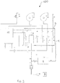
figure 2 shows , in a schematic way, a heating apparatus comprising a safety circuit according to present invention, under emergency operating condition, that is in the absence of grid current; -
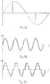
figure 3A shows, in a schematic way, an example of "phase cut" regulation on a sine wave; -
figure 3B shows, in a voltage on time chart, the shape of a pure sine wave, typical of normal home grid voltage; -
figure 3C shows, in a voltage on time chart, the shape of a modified sine wave. - A
heating apparatus 100 according to present invention is preferably formed by a solid fuel fueled stove or boiler and includes a housing structure which defines a combustion chamber, in which fuel is placed and triggered, associated with a exhaust pipe to discharge the combustion fumes. Saidapparatus 100 also includes at least at least one electric device with anadjustable speed motor 15, that is a device equipped with an electric motor and working in a modular way, that is adjustable in intensity, as for instance at least a first paddle fan, made to let combustion air in from outside theapparatus 100, conveying it into the combustion chamber and expel the combustion fumes through said exhaust pipe. - Said
first fan 15 is an adjustable speed electric device as it can operate under different power levels, and it is primary as, to ensure the correct operation ofapparatus 100 it must be able to operate both when the apparatus is under normal operating condition, that is when it is powered by the electric grid to which it is connected, and also under emergency conditions, that is in the case of a temporary lack of power supply from the electricity grid, for example due to a line failure. - Said
heating apparatus 100 also includes the first command and control means 10, as for instance an appropriately programmed electronic card to manage the functioning of saidapparatus 100 under normal conditions and under emergency conditions; in particular, under normal working conditions, said first command and control means 10 manage at least saidfirst fan 15 by adjusting the motor speed of the electric motor that powers it, in particular through a "phase cutting" system, consequently determining the intake of combustion air into the combustion chamber according to the different operating conditions ofapparatus 100, for instance in ignition or steady state, and to the level of power of use required by the user. - Said
heating apparatus 100 is also equipped with anuninterruptable power supply 8, of a known type, suitable to be activated to make up for a possible interruption in the electric power supply and maintain said at least one primary adjustable electric device operational also under emergency conditions. - Preferably, said
uninterruptable power supply 8 includes a first converter that, thanks to a rectifier and a filter, converts the alternating voltage powered by the electric grid into a continuous voltage, one or more batteries, eventually easily extractable, in which the power provided by first converter is stocked, and a second converter (or inverter) that, in the case of lack of electricity grid, takes energy from the batteries to provide power to the device placed downstream. - Said
uninterruptable power supply 8 doesn't deliver a pure sine wave, essentially equivalent to that provided by the electricity grid and shown as an example infigure 3B , but it generates a modified sine wave, shown for example infigure 3C , on which it is not possible to operate the "phase cutting" system necessary to adjust the intensity of operation of the adjustable speed electric devices. - Accordingly, an
apparatus 100 according to present invention also comprises a safety circuit 9, suitable to be electrically interposed between saiduninterruptable power supply 8 and saidfirst fan 15 to check the operation of this latter electric motor under emergency conditions, that is to say when power is supplied byuninterruptable power supply 8. - Said safety circuit 9 includes at least a capacitor C1 that, in response to the lack of grid power supply, that is under emergency conditions, determines a capacitive fall of the electric power supply supplied by the
uninterruptable power supply 8 to an operating value of the adjustable speed device associated with it appropriately preset for the emergency condition. In other words, the capacity of capacitor C1 is selected according to the operating mode that you want to impose on thefirst fan 15 under emergency conditions. - Preferably, said first capacitor C1 is such to adjust the speed of
first fan 15 to a minimum frequency, such to allow the start of a controlled shutoff procedure, if planned, or to keep the existing combustion inside theapparatus 100 active at a minimum. - Advantageously, said safety circuit 9 also includes second command and control means 19, for example formed by a CPU, suitable to activate said
uninterruptable power supply 8 under emergency conditions. - In case said
apparatus 100 includes one adjustable speed electric equipment only, constituted in particular by the motor offan 15, on the supply line of saidapparatus 100, upstream of said safety circuit 9, a mobile selector can be advantageously provided between a first position, in which the current passage through the same under normal operating conditions is excluded, and a second position, taken under emergency conditions, to allow passage of the current temporarily powered by theuninterruptable power supply 8 in the circuit 9 before the passage through theelectronic card 10 and to power the electric motor of saidfan 15 after the capacitive fall determined by capacitor C1. - Referring to
figures 1 and2 , saidapparatus 100 advantageously includes also a second adjustable speedelectric device 16, for instance formed by a second paddle fan powered by an electric motor, for distributing heat in the environment in a forced convective way to improve the thermal efficiency ofapparatus 100 and eventually allow to heat up also different environments from the one of installation. - Furthermore, preferably, said
apparatus 100 is equipped with conveyance means forsolid fuel 14 into the combustion chamber, eg. formed by a loading cochlea connected to a special gear motor to allow that fuel, preferably formed by pellet, is introduced into the combustion chamber in an automatic and controlled way. - In this case, the gear motor associated with the cochlea is configured as a not adjustable electric device, as electrically powered but with an operating mode, continuous or intermittent, however attested on a single level of power, not variable nor modular.
- Another electric device that can be implemented on said
apparatus 100 consists in an electric ignition mean forfuel 17, as for instance an electrical resistance, in jargon called "glow plug". - Then, advantageously, said safety circuit 9 will include a further capacitor C2, associated with the electric motor of said
second fan 16 for determining, under emergency conditions, a capacitive drop of the power supply provided by theuninterruptible power supply 8 to an operating value preset for the emergency condition. - In general, advantageously, said safety circuit 9 includes a number of capacitors C1, C2 ... CN corresponding to the number N of devices equipped with adjustable speed electric motor provided in the
heating apparatus 100. - Said
heating apparatus 100 also includes a switches group R, as relay, suitable to define the operation of saidapparatus 100 under normal operation conditions and under emergency conditions. - Particularly, it is provided a condition switch R5 adapted to click as soon as a blackout in power grid occurs, so to trigger safety procedure of
apparatus 100 and therefore operate said safety circuit 9 and saiduninterruptible power supply 8. In other words, the absence of grid current makes thatelectronic card 10 can no longer keep said condition switch R5 in a first position, the one taken under normal operation, making it click immediately in a second position, corresponding to the activation of safety procedure. - As soon as said condition switch R5 shifts from first position to second position, that is under emergency, this causes also the corresponding shift of a number of safety switches from a first position to a second position, so as to manage the various electric devices of
apparatus 100 under emergency conditions. - In particular, a second and third safety switch R2, R3 respectively associated to the adjustable speed
electric devices adjustable devices apparatus 100, that is said fuel ignition mean and said gear motor for conveying the pellets. - During normal operation of
apparatus 100, that is when the same is powered by the current supplied by electricity grid, said switches group R takes a first position, shown infigure 1 . Saiduninterruptible power supply 8 is powered through a first and asecond connection electronic card 10 through a third andfourth connection 4, 4', and the safety circuit 9, through afifth connection 12. - In turn the
electronic card 10 directly operates power supply ofgear motor 14 though asixth connection 6, offirst fan 15, through a seventh andeighth connection 3, 3', ofsecond fan 16 through a ninth andtenth connection 2, 2', and ofglow plug 17 through an eleventh andtwelfth connection 1, 1'. - In this condition, the
electronic card 10 provides to the adjustment ofgear motor 14 conveniently in ON-OFF mode or in phase cutting mode, and to the regulation of the adjustable speed motors of saidfans - As soon as an interruption in the supply of electricity from the grid occurs, that is under emergency conditions, said switches group R clicks in a second position, shown in
figure 2 , to activate security procedure programmed forapparatus 100; in particular, said condition switch R5 immediately assumes the second position, thus activating emergency procedure and involving the corresponding movement of security switches R1, R2, R3, R4. - This makes sure that energy is powered to said
apparatus 100 by saiduninterruptible power supply 8 through athirteenth connection 7, that connects this last one to the safety circuit 9 and to theelectronic card 10 ofapparatus 100. - Preferably, the shift into the second position of said first security switch R1 placed on pertinent
eleventh connection 1 involves the temporary exclusion of power supply of saidglow plug 17, thus stopping the current passage towards it. - Simultaneously, the energy supplied by
uninterruptible power supply 8 is directed to the not adjustable devices ofapparatus 100, namely the electric motors of the twofans - The click of said fourth security switch R4 into the second position determines instead the passage of electricity supplied by
uninterruptible power supply 8 through said fourth connection 4' to power theelectronic card 10 ofapparatus 100, and through a fourteenth and afifteenth connection 5, 5' to enable the activation of security procedure, thus enablingcard 10 to modulate trough saidsixth connection 6 thegear motor 14 using only an intermittent ON-OFF mode. - Suitably, said safety circuit 9, particularly trough capacitors C1, C2, and said
electronic card 10 work in such a way as to maintain saidapparatus 100 working with a minimum energy consumption from the motors offan gear motor 14 of the cochlea, in order to maximize battery life ofuninterruptible power supply 8. - Advantageously, said second command and control means 19 are adapted to continuously detect, thanks to a sixteenth connection 18', the voltage of the battery of
uninterruptible power supply 8, supplying the detected data to theelectronic card 10 ofapparatus 100 though aseventeenth connection 18 in such a way as to be able to determine the residual operating time tA. The working procedure of aheating apparatus 100 equipped with a solidfuel heating apparatus 100 according to present invention under emergency condition when the same is powered byuninterruptible power supply 8 is described below. - In particular, in case the duration of the lack of electricity from the grid is greater than an alert level of the residual operating time tA of the
uninterruptible power supply 8, theapparatus 100 will carry out a controlled shutoff step, in such a way that it can be safely re-ignited, when grid current returns, without inconvenience and dangerous situations for the user. - To do this, therefore, said command and control means 19 of said safety circuit 9 steadily monitor battery voltage of
uninterruptible power supply 8; when charge level of the battery falls under a determined value, and therefore the residual operating time tA reaches an alert level, preferably determined on the amount of energy necessary to operate a controlled shutoff step, a signal is sent to theelectronic card 10 ofapparatus 100 though saidseventeenth connection 18, thus interrupting the pellet supply fromgear motor 14 and allowing the controlled shutoff step of the motors of said first andsecond fan apparatus 100. - Otherwise, in case the duration of electricity blackout from the supply grid does not reach the alert level of the residual operating time tA of
uninterruptible power supply 8, when grid electricity is restored said switches group R switches back to said first position to restore in a substantially immediate way the normal operating condition ofapparatus 100, in which necessary power is provided by electricity grid, without any discomfort for the user. - Simultaneously,
electronic card 10 allows electricity provided by the electricity grid to fully charge the battery ofuninterruptible power supply 8. - Preferably, and in favor of security, in case grid current should re-establish itself during the execution of the controlled shutoff step of the stove, the latter is in any case finished.
- In conclusion, from the foresaid it is therefore evident how present invention achieves the initially planned purposes and advantages. As a matter of fact has been implemented a
heating apparatus 100 provided with a safety circuit 9 that, trough a capacitive drop regulation system implemented inside it via one or more capacitors C1, C2, ensures the regulation to the minimum power of corresponding one or more adjustable electric devices, as for instance the motors of a first andsecond fan uninterruptible power supply 8. - Moreover, an optimized operating procedure of said
heating apparatus 100 has been devised such as to allow that any temporary interruptions in the supply of electricity do not force the user to long periods of under use of the stove, and that instead any long-lasting power blackout do not cause danger to the user or damage the apparatus itself. - Generalizing, a safety circuit for an electric device with adjustable speed motor has been conceived, comprising command and control means to control the functioning of the device under emergency conditions, an uninterruptable power supply selectively operable by said command and control means to electrically power said device under emergency conditions, a capacitor electrically interposed between said uninterruptable power supply and said electric device and selectively activated by said command and control means under emergency conditions to determine a capacitive drop of the power supply provided by the uninterruptable power supply to said device to an operating value preset for the emergency condition.
- Of course the present invention is susceptible to several applications, changes or variants without thereby exiting the range of protection, as defined by the attached claims. Furthermore materials and equipments used for the implementation of present invention, as well as the shapes and sizes of the single components, can be the most suitable according to specific needs.
Claims (9)
- Solid fuel heating apparatus (100) comprising a combustion chamber for accommodating said solid fuel, at least a first fan (15) driven by an adjustable speed electric motor for allowing the inlet of combustion air into said combustion chamber and the expulsion of combustion fumes, first command and control means (10) for controlling the functioning of said apparatus (100) in normal operating conditions and under emergency conditions, and an uninterruptible power supply (8) for powering said first fan (15) under emergency conditions, characterized in that it further comprises a security circuit (9) provided with at least a first capacitor (C1) associable with said first fan (15), said security circuit (9) being electrically interposed between said uninterruptible power supply (8) and said first fan (15) for determining, under emergency conditions, a capacitive drop of the power supply provided to said first fan (15) from said uninterruptible power supply (8) to an operating value preset for the emergency conditions.
- Solid fuel heating apparatus (100) according to claim 1, further comprising a second fan (16) driven by an adjustable speed electric motor for circulating the heat out of said apparatus (100), said security circuit (9) comprising a second capacitor (C2) associable with said second fan (16) for determining, under emergency conditions, a capacitive drop of the power supply provided to said second fan (16) from said uninterruptible power supply (8) to an operating value preset for the emergency conditions.
- Solid fuel heating apparatus (100) according to claim 1 or 2, comprising means for conveying the fuel into said combustion chamber driven by a gear motor (14) controlled by said first command and control means (10).
- Solid fuel heating apparatus (100) according to any one of claims 1 to 3, wherein said security circuit (9) further comprises second command and control means (19) adapted to operate said uninterruptible power supply (8) under emergency conditions.
- Solid fuel heating apparatus (100) according to claim 4, wherein said second command and control means (19) are adapted to continuously detect the voltage of said uninterruptible power supply (8) so as to determine the residual operating time (tA).
- Solid fuel heating apparatus (100) according to claim 1, further comprising a switches group (R) adapted to define the functioning of said apparatus (100) in normal operating conditions and under emergency conditions, said switches group (R) comprising a condition switch (R5) and at least a security switch (R3) associated with said first fan (15), said condition switch (R5) being adapted to operate said security circuit (9) under emergency conditions so as to activate said uninterruptible power supply (8), said security switch (R3) being consequently operated under emergency conditions so as to allow the passage of the current flow from said uninterruptible power supply (8) towards said first fan (15), through said first capacitor (C1).
- Method of operating a solid fuel heating apparatus (100) according to claim 1 under emergency conditions, which method comprises a step of operating said security circuit (9) for determining a capacitive drop of the power supply provided from said uninterruptible power supply (8) to said first fan (15) to an operating value preset for the emergency conditions.
- Method according to claim 7 of operating a solid fuel heating apparatus (100) further comprising means for conveying the fuel into said combustion chamber driven by a gear motor (14) wherein when said security circuit (9) is operated, said gear motor (14) is powered in an intermittent mode.
- Method according to claim 7 of operating a solid fuel heating apparatus (100) further comprising means for conveying the fuel into said combustion chamber driven by a gear motor (14) and second command and control means (19) adapted to continuously detect the voltage of said uninterruptible power supply (8) so as to determine the residual operating time (tA), wherein when said residual operating time (tA) reaches a preset alert level, an automatic shutoff step of said apparatus (100) is operated by interrupting the power supply to said gear motor (14) of said fuel conveying means and by powering said first fan (15) allowing the passage of the current flow through said first capacitor (C1) so as to complete the combustion of the fuel already loaded in said combustion chamber.
Applications Claiming Priority (1)
| Application Number | Priority Date | Filing Date | Title |
|---|---|---|---|
| IT102017000053090A IT201700053090A1 (en) | 2017-05-16 | 2017-05-16 | HEATING EQUIPMENT WITH SOLID FUEL EQUIPPED WITH A SAFETY CIRCUIT AND ITS OPERATING PROCEDURE IN EMERGENCY CONDITIONS |
Publications (2)
| Publication Number | Publication Date |
|---|---|
| EP3404328A1 EP3404328A1 (en) | 2018-11-21 |
| EP3404328B1 true EP3404328B1 (en) | 2019-05-15 |
Family
ID=59974767
Family Applications (1)
| Application Number | Title | Priority Date | Filing Date |
|---|---|---|---|
| EP18171032.8A Active EP3404328B1 (en) | 2017-05-16 | 2018-05-07 | Solid fuel heating apparatus provided with a safety circuit and related operating method under emergency conditions |
Country Status (2)
| Country | Link |
|---|---|
| EP (1) | EP3404328B1 (en) |
| IT (1) | IT201700053090A1 (en) |
Family Cites Families (3)
| Publication number | Priority date | Publication date | Assignee | Title |
|---|---|---|---|---|
| JPS5659128A (en) * | 1979-10-19 | 1981-05-22 | Matsushita Electric Ind Co Ltd | System controller for gas appliance |
| JP2016109355A (en) * | 2014-12-05 | 2016-06-20 | 三浦工業株式会社 | boiler |
| JP6511658B2 (en) * | 2015-04-22 | 2019-05-15 | 株式会社奥美濃プロデュース | Emergency power supply for pellet stove and pellet stove incorporating the same |
-
2017
- 2017-05-16 IT IT102017000053090A patent/IT201700053090A1/en unknown
-
2018
- 2018-05-07 EP EP18171032.8A patent/EP3404328B1/en active Active
Non-Patent Citations (1)
| Title |
|---|
| None * |
Also Published As
| Publication number | Publication date |
|---|---|
| IT201700053090A1 (en) | 2018-11-16 |
| EP3404328A1 (en) | 2018-11-21 |
Similar Documents
| Publication | Publication Date | Title |
|---|---|---|
| RU2486411C2 (en) | Gas burner ignition system (versions) | |
| US11268695B2 (en) | Method and system for starting an intermittent flame-powered pilot combustion system | |
| US11719467B2 (en) | Method and system for controlling an intermittent pilot water heater system | |
| US11719436B2 (en) | Method and system for controlling an ignition sequence for an intermittent flame-powered pilot combustion system | |
| US20100075264A1 (en) | Redundant Ignition Control Circuit and Method | |
| US11322674B2 (en) | Portable thermal power station | |
| EP2028420A1 (en) | System of automatic feeding of furnaces with liquid fuel | |
| EP3404328A1 (en) | Solid fuel heating apparatus provided with a safety circuit and related operating method under emergency conditions | |
| JP6137771B2 (en) | Hot water supply apparatus and power supply method thereof | |
| JP6511658B2 (en) | Emergency power supply for pellet stove and pellet stove incorporating the same | |
| CN1133849C (en) | Burner | |
| CN212875692U (en) | Thermoelectric generation's cooking utensils electrical power generating system | |
| JP4851399B2 (en) | Cogeneration system and its hot water storage unit | |
| JP2017228483A (en) | Control device | |
| RU2183797C1 (en) | Device for monitoring and control of gas heat generator | |
| JP2016156594A (en) | Boiler system | |
| RU98105779A (en) | MODULAR FIRE HEAT GENERATING INSTALLATION AND METHOD FOR AUTOMATIC CONTROL OF ITS OPERATION | |
| KR100212512B1 (en) | Heating control method for large volume gas boiler | |
| KR0121099B1 (en) | Microcomputer controlled heating device | |
| CN212909063U (en) | AC/DC dual-purpose fuel oil warm air blower | |
| CN202845365U (en) | Explosion-proof type hot and cold water cleaning machine | |
| KR200203286Y1 (en) | Safety cut-off circuit in the event of a microcomputer failure in the boiler | |
| JP2013194514A (en) | Cogeneration system | |
| KR0153712B1 (en) | Heater | |
| JP6404888B2 (en) | Water heater |
Legal Events
| Date | Code | Title | Description |
|---|---|---|---|
| PUAI | Public reference made under article 153(3) epc to a published international application that has entered the european phase |
Free format text: ORIGINAL CODE: 0009012 |
|
| STAA | Information on the status of an ep patent application or granted ep patent |
Free format text: STATUS: THE APPLICATION HAS BEEN PUBLISHED |
|
| AK | Designated contracting states |
Kind code of ref document: A1 Designated state(s): AL AT BE BG CH CY CZ DE DK EE ES FI FR GB GR HR HU IE IS IT LI LT LU LV MC MK MT NL NO PL PT RO RS SE SI SK SM TR |
|
| AX | Request for extension of the european patent |
Extension state: BA ME |
|
| STAA | Information on the status of an ep patent application or granted ep patent |
Free format text: STATUS: REQUEST FOR EXAMINATION WAS MADE |
|
| GRAP | Despatch of communication of intention to grant a patent |
Free format text: ORIGINAL CODE: EPIDOSNIGR1 |
|
| STAA | Information on the status of an ep patent application or granted ep patent |
Free format text: STATUS: GRANT OF PATENT IS INTENDED |
|
| 17P | Request for examination filed |
Effective date: 20190118 |
|
| RBV | Designated contracting states (corrected) |
Designated state(s): AL AT BE BG CH CY CZ DE DK EE ES FI FR GB GR HR HU IE IS IT LI LT LU LV MC MK MT NL NO PL PT RO RS SE SI SK SM TR |
|
| INTG | Intention to grant announced |
Effective date: 20190222 |
|
| GRAS | Grant fee paid |
Free format text: ORIGINAL CODE: EPIDOSNIGR3 |
|
| GRAA | (expected) grant |
Free format text: ORIGINAL CODE: 0009210 |
|
| STAA | Information on the status of an ep patent application or granted ep patent |
Free format text: STATUS: THE PATENT HAS BEEN GRANTED |
|
| AK | Designated contracting states |
Kind code of ref document: B1 Designated state(s): AL AT BE BG CH CY CZ DE DK EE ES FI FR GB GR HR HU IE IS IT LI LT LU LV MC MK MT NL NO PL PT RO RS SE SI SK SM TR |
|
| REG | Reference to a national code |
Ref country code: CH Ref legal event code: EP |
|
| REG | Reference to a national code |
Ref country code: DE Ref legal event code: R096 Ref document number: 602018000088 Country of ref document: DE |
|
| REG | Reference to a national code |
Ref country code: IE Ref legal event code: FG4D |
|
| REG | Reference to a national code |
Ref country code: NL Ref legal event code: MP Effective date: 20190515 |
|
| REG | Reference to a national code |
Ref country code: LT Ref legal event code: MG4D |
|
| PG25 | Lapsed in a contracting state [announced via postgrant information from national office to epo] |
Ref country code: AL Free format text: LAPSE BECAUSE OF FAILURE TO SUBMIT A TRANSLATION OF THE DESCRIPTION OR TO PAY THE FEE WITHIN THE PRESCRIBED TIME-LIMIT Effective date: 20190515 Ref country code: NL Free format text: LAPSE BECAUSE OF FAILURE TO SUBMIT A TRANSLATION OF THE DESCRIPTION OR TO PAY THE FEE WITHIN THE PRESCRIBED TIME-LIMIT Effective date: 20190515 Ref country code: LT Free format text: LAPSE BECAUSE OF FAILURE TO SUBMIT A TRANSLATION OF THE DESCRIPTION OR TO PAY THE FEE WITHIN THE PRESCRIBED TIME-LIMIT Effective date: 20190515 Ref country code: FI Free format text: LAPSE BECAUSE OF FAILURE TO SUBMIT A TRANSLATION OF THE DESCRIPTION OR TO PAY THE FEE WITHIN THE PRESCRIBED TIME-LIMIT Effective date: 20190515 Ref country code: ES Free format text: LAPSE BECAUSE OF FAILURE TO SUBMIT A TRANSLATION OF THE DESCRIPTION OR TO PAY THE FEE WITHIN THE PRESCRIBED TIME-LIMIT Effective date: 20190515 Ref country code: SE Free format text: LAPSE BECAUSE OF FAILURE TO SUBMIT A TRANSLATION OF THE DESCRIPTION OR TO PAY THE FEE WITHIN THE PRESCRIBED TIME-LIMIT Effective date: 20190515 Ref country code: HR Free format text: LAPSE BECAUSE OF FAILURE TO SUBMIT A TRANSLATION OF THE DESCRIPTION OR TO PAY THE FEE WITHIN THE PRESCRIBED TIME-LIMIT Effective date: 20190515 Ref country code: NO Free format text: LAPSE BECAUSE OF FAILURE TO SUBMIT A TRANSLATION OF THE DESCRIPTION OR TO PAY THE FEE WITHIN THE PRESCRIBED TIME-LIMIT Effective date: 20190815 Ref country code: PT Free format text: LAPSE BECAUSE OF FAILURE TO SUBMIT A TRANSLATION OF THE DESCRIPTION OR TO PAY THE FEE WITHIN THE PRESCRIBED TIME-LIMIT Effective date: 20190915 |
|
| PG25 | Lapsed in a contracting state [announced via postgrant information from national office to epo] |
Ref country code: LV Free format text: LAPSE BECAUSE OF FAILURE TO SUBMIT A TRANSLATION OF THE DESCRIPTION OR TO PAY THE FEE WITHIN THE PRESCRIBED TIME-LIMIT Effective date: 20190515 Ref country code: RS Free format text: LAPSE BECAUSE OF FAILURE TO SUBMIT A TRANSLATION OF THE DESCRIPTION OR TO PAY THE FEE WITHIN THE PRESCRIBED TIME-LIMIT Effective date: 20190515 Ref country code: GR Free format text: LAPSE BECAUSE OF FAILURE TO SUBMIT A TRANSLATION OF THE DESCRIPTION OR TO PAY THE FEE WITHIN THE PRESCRIBED TIME-LIMIT Effective date: 20190816 Ref country code: BG Free format text: LAPSE BECAUSE OF FAILURE TO SUBMIT A TRANSLATION OF THE DESCRIPTION OR TO PAY THE FEE WITHIN THE PRESCRIBED TIME-LIMIT Effective date: 20190815 |
|
| REG | Reference to a national code |
Ref country code: AT Ref legal event code: MK05 Ref document number: 1133879 Country of ref document: AT Kind code of ref document: T Effective date: 20190515 |
|
| PG25 | Lapsed in a contracting state [announced via postgrant information from national office to epo] |
Ref country code: CZ Free format text: LAPSE BECAUSE OF FAILURE TO SUBMIT A TRANSLATION OF THE DESCRIPTION OR TO PAY THE FEE WITHIN THE PRESCRIBED TIME-LIMIT Effective date: 20190515 Ref country code: SK Free format text: LAPSE BECAUSE OF FAILURE TO SUBMIT A TRANSLATION OF THE DESCRIPTION OR TO PAY THE FEE WITHIN THE PRESCRIBED TIME-LIMIT Effective date: 20190515 Ref country code: AT Free format text: LAPSE BECAUSE OF FAILURE TO SUBMIT A TRANSLATION OF THE DESCRIPTION OR TO PAY THE FEE WITHIN THE PRESCRIBED TIME-LIMIT Effective date: 20190515 Ref country code: DK Free format text: LAPSE BECAUSE OF FAILURE TO SUBMIT A TRANSLATION OF THE DESCRIPTION OR TO PAY THE FEE WITHIN THE PRESCRIBED TIME-LIMIT Effective date: 20190515 Ref country code: EE Free format text: LAPSE BECAUSE OF FAILURE TO SUBMIT A TRANSLATION OF THE DESCRIPTION OR TO PAY THE FEE WITHIN THE PRESCRIBED TIME-LIMIT Effective date: 20190515 |
|
| REG | Reference to a national code |
Ref country code: DE Ref legal event code: R097 Ref document number: 602018000088 Country of ref document: DE |
|
| PG25 | Lapsed in a contracting state [announced via postgrant information from national office to epo] |
Ref country code: SM Free format text: LAPSE BECAUSE OF FAILURE TO SUBMIT A TRANSLATION OF THE DESCRIPTION OR TO PAY THE FEE WITHIN THE PRESCRIBED TIME-LIMIT Effective date: 20190515 Ref country code: IT Free format text: LAPSE BECAUSE OF FAILURE TO SUBMIT A TRANSLATION OF THE DESCRIPTION OR TO PAY THE FEE WITHIN THE PRESCRIBED TIME-LIMIT Effective date: 20190515 |
|
| PLBE | No opposition filed within time limit |
Free format text: ORIGINAL CODE: 0009261 |
|
| STAA | Information on the status of an ep patent application or granted ep patent |
Free format text: STATUS: NO OPPOSITION FILED WITHIN TIME LIMIT |
|
| PG25 | Lapsed in a contracting state [announced via postgrant information from national office to epo] |
Ref country code: TR Free format text: LAPSE BECAUSE OF FAILURE TO SUBMIT A TRANSLATION OF THE DESCRIPTION OR TO PAY THE FEE WITHIN THE PRESCRIBED TIME-LIMIT Effective date: 20190515 |
|
| 26N | No opposition filed |
Effective date: 20200218 |
|
| PG25 | Lapsed in a contracting state [announced via postgrant information from national office to epo] |
Ref country code: PL Free format text: LAPSE BECAUSE OF FAILURE TO SUBMIT A TRANSLATION OF THE DESCRIPTION OR TO PAY THE FEE WITHIN THE PRESCRIBED TIME-LIMIT Effective date: 20190515 |
|
| PG25 | Lapsed in a contracting state [announced via postgrant information from national office to epo] |
Ref country code: MC Free format text: LAPSE BECAUSE OF FAILURE TO SUBMIT A TRANSLATION OF THE DESCRIPTION OR TO PAY THE FEE WITHIN THE PRESCRIBED TIME-LIMIT Effective date: 20190515 |
|
| PG25 | Lapsed in a contracting state [announced via postgrant information from national office to epo] |
Ref country code: LU Free format text: LAPSE BECAUSE OF NON-PAYMENT OF DUE FEES Effective date: 20200507 |
|
| PG25 | Lapsed in a contracting state [announced via postgrant information from national office to epo] |
Ref country code: IE Free format text: LAPSE BECAUSE OF NON-PAYMENT OF DUE FEES Effective date: 20200507 |
|
| REG | Reference to a national code |
Ref country code: CH Ref legal event code: PL |
|
| PG25 | Lapsed in a contracting state [announced via postgrant information from national office to epo] |
Ref country code: LI Free format text: LAPSE BECAUSE OF NON-PAYMENT OF DUE FEES Effective date: 20210531 Ref country code: CH Free format text: LAPSE BECAUSE OF NON-PAYMENT OF DUE FEES Effective date: 20210531 |
|
| PG25 | Lapsed in a contracting state [announced via postgrant information from national office to epo] |
Ref country code: MT Free format text: LAPSE BECAUSE OF FAILURE TO SUBMIT A TRANSLATION OF THE DESCRIPTION OR TO PAY THE FEE WITHIN THE PRESCRIBED TIME-LIMIT Effective date: 20190515 Ref country code: CY Free format text: LAPSE BECAUSE OF FAILURE TO SUBMIT A TRANSLATION OF THE DESCRIPTION OR TO PAY THE FEE WITHIN THE PRESCRIBED TIME-LIMIT Effective date: 20190515 |
|
| PG25 | Lapsed in a contracting state [announced via postgrant information from national office to epo] |
Ref country code: RO Free format text: LAPSE BECAUSE OF FAILURE TO SUBMIT A TRANSLATION OF THE DESCRIPTION OR TO PAY THE FEE WITHIN THE PRESCRIBED TIME-LIMIT Effective date: 20190515 Ref country code: MK Free format text: LAPSE BECAUSE OF FAILURE TO SUBMIT A TRANSLATION OF THE DESCRIPTION OR TO PAY THE FEE WITHIN THE PRESCRIBED TIME-LIMIT Effective date: 20190515 Ref country code: IS Free format text: LAPSE BECAUSE OF FAILURE TO SUBMIT A TRANSLATION OF THE DESCRIPTION OR TO PAY THE FEE WITHIN THE PRESCRIBED TIME-LIMIT Effective date: 20190915 |
|
| GBPC | Gb: european patent ceased through non-payment of renewal fee |
Effective date: 20220507 |
|
| PG25 | Lapsed in a contracting state [announced via postgrant information from national office to epo] |
Ref country code: GB Free format text: LAPSE BECAUSE OF NON-PAYMENT OF DUE FEES Effective date: 20220507 |
|
| PG25 | Lapsed in a contracting state [announced via postgrant information from national office to epo] |
Ref country code: SI Free format text: LAPSE BECAUSE OF FAILURE TO SUBMIT A TRANSLATION OF THE DESCRIPTION OR TO PAY THE FEE WITHIN THE PRESCRIBED TIME-LIMIT Effective date: 20190515 |
|
| PGFP | Annual fee paid to national office [announced via postgrant information from national office to epo] |
Ref country code: DE Payment date: 20240521 Year of fee payment: 7 |
|
| PGFP | Annual fee paid to national office [announced via postgrant information from national office to epo] |
Ref country code: FR Payment date: 20240528 Year of fee payment: 7 |
|
| PGFP | Annual fee paid to national office [announced via postgrant information from national office to epo] |
Ref country code: BE Payment date: 20240521 Year of fee payment: 7 |
|
| REG | Reference to a national code |
Ref country code: DE Ref legal event code: R119 Ref document number: 602018000088 Country of ref document: DE |
|
| REG | Reference to a national code |
Ref country code: BE Ref legal event code: MM Effective date: 20250531 |
|
| PG25 | Lapsed in a contracting state [announced via postgrant information from national office to epo] |
Ref country code: DE Free format text: LAPSE BECAUSE OF NON-PAYMENT OF DUE FEES Effective date: 20251202 |
|
| PG25 | Lapsed in a contracting state [announced via postgrant information from national office to epo] |
Ref country code: BE Free format text: LAPSE BECAUSE OF NON-PAYMENT OF DUE FEES Effective date: 20250531 |
|
| PG25 | Lapsed in a contracting state [announced via postgrant information from national office to epo] |
Ref country code: FR Free format text: LAPSE BECAUSE OF NON-PAYMENT OF DUE FEES Effective date: 20250531 |