EP3404257A1 - System and method for controlling a pitch angle of a wind turbine rotor blade - Google Patents
System and method for controlling a pitch angle of a wind turbine rotor blade Download PDFInfo
- Publication number
- EP3404257A1 EP3404257A1 EP18171680.4A EP18171680A EP3404257A1 EP 3404257 A1 EP3404257 A1 EP 3404257A1 EP 18171680 A EP18171680 A EP 18171680A EP 3404257 A1 EP3404257 A1 EP 3404257A1
- Authority
- EP
- European Patent Office
- Prior art keywords
- wind
- parameter
- wind turbine
- controller
- rotor blade
- Prior art date
- Legal status (The legal status is an assumption and is not a legal conclusion. Google has not performed a legal analysis and makes no representation as to the accuracy of the status listed.)
- Granted
Links
Images


Classifications
-
- F—MECHANICAL ENGINEERING; LIGHTING; HEATING; WEAPONS; BLASTING
- F03—MACHINES OR ENGINES FOR LIQUIDS; WIND, SPRING, OR WEIGHT MOTORS; PRODUCING MECHANICAL POWER OR A REACTIVE PROPULSIVE THRUST, NOT OTHERWISE PROVIDED FOR
- F03D—WIND MOTORS
- F03D7/00—Controlling wind motors
- F03D7/02—Controlling wind motors the wind motors having rotation axis substantially parallel to the air flow entering the rotor
- F03D7/022—Adjusting aerodynamic properties of the blades
- F03D7/0224—Adjusting blade pitch
-
- F—MECHANICAL ENGINEERING; LIGHTING; HEATING; WEAPONS; BLASTING
- F03—MACHINES OR ENGINES FOR LIQUIDS; WIND, SPRING, OR WEIGHT MOTORS; PRODUCING MECHANICAL POWER OR A REACTIVE PROPULSIVE THRUST, NOT OTHERWISE PROVIDED FOR
- F03D—WIND MOTORS
- F03D17/00—Monitoring or testing of wind motors, e.g. diagnostics
-
- F—MECHANICAL ENGINEERING; LIGHTING; HEATING; WEAPONS; BLASTING
- F03—MACHINES OR ENGINES FOR LIQUIDS; WIND, SPRING, OR WEIGHT MOTORS; PRODUCING MECHANICAL POWER OR A REACTIVE PROPULSIVE THRUST, NOT OTHERWISE PROVIDED FOR
- F03D—WIND MOTORS
- F03D7/00—Controlling wind motors
- F03D7/02—Controlling wind motors the wind motors having rotation axis substantially parallel to the air flow entering the rotor
- F03D7/022—Adjusting aerodynamic properties of the blades
- F03D7/024—Adjusting aerodynamic properties of the blades of individual blades
-
- F—MECHANICAL ENGINEERING; LIGHTING; HEATING; WEAPONS; BLASTING
- F03—MACHINES OR ENGINES FOR LIQUIDS; WIND, SPRING, OR WEIGHT MOTORS; PRODUCING MECHANICAL POWER OR A REACTIVE PROPULSIVE THRUST, NOT OTHERWISE PROVIDED FOR
- F03D—WIND MOTORS
- F03D7/00—Controlling wind motors
- F03D7/02—Controlling wind motors the wind motors having rotation axis substantially parallel to the air flow entering the rotor
- F03D7/028—Controlling wind motors the wind motors having rotation axis substantially parallel to the air flow entering the rotor controlling wind motor output power
- F03D7/0292—Controlling wind motors the wind motors having rotation axis substantially parallel to the air flow entering the rotor controlling wind motor output power to reduce fatigue
-
- F—MECHANICAL ENGINEERING; LIGHTING; HEATING; WEAPONS; BLASTING
- F03—MACHINES OR ENGINES FOR LIQUIDS; WIND, SPRING, OR WEIGHT MOTORS; PRODUCING MECHANICAL POWER OR A REACTIVE PROPULSIVE THRUST, NOT OTHERWISE PROVIDED FOR
- F03D—WIND MOTORS
- F03D7/00—Controlling wind motors
- F03D7/02—Controlling wind motors the wind motors having rotation axis substantially parallel to the air flow entering the rotor
- F03D7/04—Automatic control; Regulation
- F03D7/042—Automatic control; Regulation by means of an electrical or electronic controller
-
- F—MECHANICAL ENGINEERING; LIGHTING; HEATING; WEAPONS; BLASTING
- F05—INDEXING SCHEMES RELATING TO ENGINES OR PUMPS IN VARIOUS SUBCLASSES OF CLASSES F01-F04
- F05B—INDEXING SCHEME RELATING TO WIND, SPRING, WEIGHT, INERTIA OR LIKE MOTORS, TO MACHINES OR ENGINES FOR LIQUIDS COVERED BY SUBCLASSES F03B, F03D AND F03G
- F05B2270/00—Control
- F05B2270/10—Purpose of the control system
- F05B2270/109—Purpose of the control system to prolong engine life
- F05B2270/1095—Purpose of the control system to prolong engine life by limiting mechanical stresses
-
- F—MECHANICAL ENGINEERING; LIGHTING; HEATING; WEAPONS; BLASTING
- F05—INDEXING SCHEMES RELATING TO ENGINES OR PUMPS IN VARIOUS SUBCLASSES OF CLASSES F01-F04
- F05B—INDEXING SCHEME RELATING TO WIND, SPRING, WEIGHT, INERTIA OR LIKE MOTORS, TO MACHINES OR ENGINES FOR LIQUIDS COVERED BY SUBCLASSES F03B, F03D AND F03G
- F05B2270/00—Control
- F05B2270/30—Control parameters, e.g. input parameters
- F05B2270/32—Wind speeds
-
- F—MECHANICAL ENGINEERING; LIGHTING; HEATING; WEAPONS; BLASTING
- F05—INDEXING SCHEMES RELATING TO ENGINES OR PUMPS IN VARIOUS SUBCLASSES OF CLASSES F01-F04
- F05B—INDEXING SCHEME RELATING TO WIND, SPRING, WEIGHT, INERTIA OR LIKE MOTORS, TO MACHINES OR ENGINES FOR LIQUIDS COVERED BY SUBCLASSES F03B, F03D AND F03G
- F05B2270/00—Control
- F05B2270/30—Control parameters, e.g. input parameters
- F05B2270/321—Wind directions
-
- F—MECHANICAL ENGINEERING; LIGHTING; HEATING; WEAPONS; BLASTING
- F05—INDEXING SCHEMES RELATING TO ENGINES OR PUMPS IN VARIOUS SUBCLASSES OF CLASSES F01-F04
- F05B—INDEXING SCHEME RELATING TO WIND, SPRING, WEIGHT, INERTIA OR LIKE MOTORS, TO MACHINES OR ENGINES FOR LIQUIDS COVERED BY SUBCLASSES F03B, F03D AND F03G
- F05B2270/00—Control
- F05B2270/30—Control parameters, e.g. input parameters
- F05B2270/332—Maximum loads or fatigue criteria
-
- Y—GENERAL TAGGING OF NEW TECHNOLOGICAL DEVELOPMENTS; GENERAL TAGGING OF CROSS-SECTIONAL TECHNOLOGIES SPANNING OVER SEVERAL SECTIONS OF THE IPC; TECHNICAL SUBJECTS COVERED BY FORMER USPC CROSS-REFERENCE ART COLLECTIONS [XRACs] AND DIGESTS
- Y02—TECHNOLOGIES OR APPLICATIONS FOR MITIGATION OR ADAPTATION AGAINST CLIMATE CHANGE
- Y02E—REDUCTION OF GREENHOUSE GAS [GHG] EMISSIONS, RELATED TO ENERGY GENERATION, TRANSMISSION OR DISTRIBUTION
- Y02E10/00—Energy generation through renewable energy sources
- Y02E10/70—Wind energy
- Y02E10/72—Wind turbines with rotation axis in wind direction
Definitions
- the present disclosure generally relates to wind turbines. More particularly, the present disclosure relates to systems and methods for controlling for controlling pitch angles of wind turbine rotor blades.
- Wind power is considered one of the cleanest, most environmentally friendly energy sources presently available, and wind turbines have gained increased attention in this regard.
- a modern wind turbine typically includes a tower, a nacelle mounted on the tower, a generator positioned in the nacelle, and one or more rotor blades.
- the one or more rotor blades convert kinetic energy of wind into mechanical energy using known airfoil principles.
- a drivetrain transmits the mechanical energy from the rotor blades to the generator.
- the generator then converts the mechanical energy into electrical energy that may be supplied to a utility grid.
- the orientation of the rotor blades may be adjustable to control the amount of kinetic energy extracted from the wind. More specifically, the rotor blades may be rotatably coupled to the hub. In this respect, a pitch adjustment mechanism may rotate each rotor blade about a corresponding pitch axis to adjust a pitch angle of the rotor blade. As such, the pitch angles of the rotor blades may be adjusted between a feathered position where a minimum amount kinetic energy extracted from the wind and a power position where a maximum amount kinetic energy extracted from the wind.
- the pitch adjustment mechanisms may adjust the pitch angles of the rotor blades to control these load imbalances. Reducing the load imbalances on the rotor blades other wind turbine components may reduce the wear thereon and extend the service life thereof. However, adjusting the pitch angles of the rotor blades may increase the wear on and reduce the service life of the pitch adjustment mechanisms.
- the present disclosure is directed to a system for controlling a pitch angle of a rotor blade of a wind turbine.
- the system includes a rotor having a hub and a rotor blade.
- the system also includes a pitch adjustment mechanism for adjusting the pitch angle of the rotor blade by rotating the rotor blade about a pitch axis relative to the hub.
- the system further includes a controller communicatively coupled to the pitch adjustment mechanism.
- the controller is configured to determine a wind asymmetry parameter based on an operating parameter of the wind turbine.
- the wind asymmetry parameter is indicative of an asymmetry in the wind experienced by the wind turbine.
- the controller is also configured to determine first and second signal components of the wind asymmetry parameter.
- the first signal component is indicative of a maximum load on a first wind turbine component.
- the second signal component is indicative of fatigue on a second wind turbine component.
- the controller is further configured to calculate a wear parameter for the first and second wind turbine components based on the first and second signal components. Furthermore, the controller is configured to initiate an adjustment of the pitch angle of the rotor blade based on the wear parameter.
- the present disclosure is directed to a method for controlling a pitch angle of a rotor blade of a wind turbine.
- the method includes determining, with a controller, a wind asymmetry parameter based on an operating parameter of the wind turbine.
- the wind asymmetry parameter is indicative of an asymmetry in the wind experienced by the wind turbine.
- the method also includes determining, with the controller, first and second signal components of the wind asymmetry parameter.
- the first signal component is indicative of a maximum load on a first wind turbine component.
- the second signal component is indicative of fatigue on a second wind turbine component.
- the method further includes calculating, with the controller, a wear parameter for the first and second wind turbine components based on the first and second signal components. Furthermore, the method includes determining, with an actuator, an adjustment of the pitch angle of the rotor blade based on the wear parameter.
- the present disclosure is directed to a method for controlling a pitch angle of a rotor blade of a wind turbine.
- the method includes determining, with a controller, a wind asymmetry parameter based on an operating parameter of the wind turbine.
- the wind asymmetry parameter is indicative of an asymmetry in the wind experienced by the wind turbine.
- the method also includes determining, with the controller, first and second signal components of the wind asymmetry parameter.
- the first signal component is indicative of a maximum load on the rotor blade.
- the second signal component is indicative of fatigue on a pitch adjustment mechanism.
- the method further includes calculating, with the controller, a wear parameter for the first and second wind turbine components based on the first and second signal components.
- the method includes determining, with an actuator, an adjustment of the pitch angle of the rotor blade based on the wear parameter.
- FIG. 1 is a perspective view of one embodiment of an exemplary wind turbine 10.
- the wind turbine 10 generally includes a tower 12 extending from a support surface 14, a nacelle 16 mounted on the tower 12, and a rotor 18 coupled to the nacelle 16.
- the rotor 18 includes a rotatable hub 20 and at least one rotor blade 22 coupled to and extending outwardly from the hub 20.
- the rotor 18 includes three rotor blades 22. In alternative embodiments, however, the rotor 18 may include more or less than three rotor blades 22.
- Each rotor blade 22 may be spaced about the hub 20 to facilitate rotating the rotor 18 to convert kinetic energy from the wind into usable rotational, mechanical energy.
- a generator 24 positioned in the nacelle 16 may generate electrical power from the rotational energy of the rotor 18.
- a drivetrain 26 rotatably couples the rotor 18 to the electric generator 24.
- the drivetrain 26 may include a rotor shaft 28, which rotatably couples the hub 20 of the rotor 18 to a gearbox 30.
- the gearbox 30 may be supported by and coupled to a bedplate 32 in the nacelle 16.
- the drivetrain 26 may also include a generator shaft 34, which rotatably couples the gearbox 30 to the generator 24.
- rotation of the rotor 18 drives the generator 24.
- the rotor shaft 28 may provide a low speed, high torque input to the gearbox 30 in response to rotation of the rotor blades 22 and the hub 20.
- the gearbox 30 may then convert the low speed, high torque input into a high speed, low torque output to drive the generator shaft 34 and, thus, the generator 24.
- the generator 24 may be directly rotatably coupled to the rotor shaft 28 in a direct-drive configuration.
- the wind turbine 10 may also include one or more pitch adjustment mechanisms 36. Although FIG. 2 only illustrates one pitch adjustment mechanism 36, the wind turbine 10 may include three pitch adjustment mechanisms 36. In this respect, the wind turbine 10 may include one pitch adjustment mechanism 36 corresponding to each rotor blade 22. In alternate embodiments, however, the wind turbine 10 may include more or fewer pitch adjustment mechanisms 36.
- Each pitch adjustment mechanism 36 may adjust a pitch angle of the corresponding rotor blade 22 (i.e., the angular orientation of the rotor blade 22 with respect to a direction 38 ( FIG. 1 ) of the wind).
- each rotor blade 22 may be rotatably coupled to the hub 20 by a pitch bearing (not shown). As such, each pitch adjustment mechanism 36 may rotate the corresponding rotor blade 22 about a corresponding pitch axis 40 ( FIG. 1 ) relative to the hub 20, thereby adjusting the pitch angle of the rotor blade 22.
- FIG. 2 illustrates an exemplary embodiment of one of the pitch adjustment mechanisms 36.
- the pitch adjustment mechanism 36 may include an electric motor 42 having a pinion gear 44 coupled thereto.
- the pinion gear 44 may engage a ring gear 46 formed on or coupled to an inner surface of the rotor blade 22.
- the electric motor 42 rotates the pinion gear 44.
- the pinion gear 44 rotates the ring gear 46, thereby rotating the rotor blade 22 about the corresponding pitch axis 40.
- the pitch adjustment mechanism 36 may include any suitable type of actuator and/or any suitable structure or mechanism for transmitting the movement of the actuator to the corresponding rotor blade 22.
- the wind turbine 10 may further include various sensors.
- the wind turbine 10 includes a pitch angle sensor 48, a rotor blade acceleration sensor 50, a rotor blade deflection sensor 52, a rotor shaft position sensor 54, a rotor shaft deflection sensor 56, and a wind speed sensor 58.
- the wind turbine 10 may include only some of the sensors 48, 50, 52, 54, 56, 58 or none of the sensors 48, 50, 52, 54, 56, 58.
- the wind turbine 10 may include other sensors in addition to or lieu of the sensors 48, 50, 52, 54, 56, 58.
- the pitch angle sensor 48 detects a pitch angle of the corresponding rotor blade 22.
- the pitch angle sensor 48 is operatively coupled to one of the rotor blades 22 as shown in FIG. 2 .
- the wind turbine 10 may include one pitch angle sensor 48 operatively coupled to each rotor blade 22.
- the pitch angle sensor 48 may be a Hall Effect sensor or any other suitable type of sensor for detecting absolute or incremental rotational position.
- the rotor blade acceleration sensor 50 detects an acceleration of the corresponding rotor blade 22.
- the rotor blade acceleration sensor 50 is operatively coupled to one of the rotor blades 22 as shown in FIG. 2 .
- the wind turbine 10 may include one rotor blade acceleration sensor 50 operatively coupled to each rotor blade 22.
- the rotor blade acceleration sensor 50 may be a micro inertial measurement unit or any other suitable type of sensor for detecting acceleration.
- the rotor blade deflection sensor 52 detects a deflection of one of the rotor blade 22, such as a deflection caused by asymmetries in the wind.
- the load sensor 52 maybe operatively coupled to the corresponding rotor blade 22 as shown in FIG. 2 .
- the system 100 may include one rotor blade deflection sensor 52 operatively coupled to each rotor blade 22.
- the rotor blade deflection sensor 52 may be a strain gauge, proximity sensor, or any other suitable type of sensor for detecting deflection.
- the rotor shaft position sensor 54 detects a rotational position of the rotor shaft 28.
- the rotational position of the rotor shaft 28 may be used to determine the rotational velocity of the rotor blades 22.
- the rotor shaft position sensor 54 is operatively coupled to a rotor shaft 28.
- the rotor shaft position sensor 54 may be a Hall Effect sensor or any other suitable type of sensor for detecting absolute or incremental rotational position.
- the rotor shaft deflection sensor 56 detects a deflection of the rotor shaft 28, such as a deflection caused by an asymmetry in the wind.
- the rotor shaft deflection sensor 56 may be operatively coupled to the rotor shaft 28 as shown in FIG. 2 .
- the rotor shaft deflection sensor 56 may be a strain gauge, proximity sensor, or any other suitable type of sensor for detecting the deflection.
- the wind speed sensor 58 detects a speed of the wind experienced by the wind turbine 10.
- the wind speed sensor 58 is mounted to the exterior of the nacelle 16.
- the wind speed sensor 58 maybe a suitable anemometer or a wind vane.
- the wind speed sensor 58 may be a light detection and ranging (LIDAR) sensor, an ultrasonic sensor, or any other suitable type of sensor for detecting wind velocity.
- the wind turbine 10 may include a plurality of wind speed sensors 58 to detect the speed of the wind at different locations, such as two vertically spaced apart anemometers.
- the wind speed sensor 58 may be separate from the wind turbine 10, such as a wind speed measurement tower for a wind turbine farm.
- FIG. 3 illustrates a system 100 for controlling the pitch angle of the rotor blades 22 of the wind turbine 10.
- asymmetries in the wind may cause load imbalances on certain components of the wind turbine 10.
- the system 100 controls the pitch angle of the rotor blades 22 to distribute the wear caused by these load imbalances across various components of the wind turbine 10.
- the system 100 may include a sensor 102 for detecting an operating parameter of the wind turbine 10.
- the operating parameter may be associated with or is indicative an asymmetry in the wind experienced by the wind turbine 10.
- the operating parameter may be a pitch angle of one or more of the rotor blades 22, an acceleration of one or more of the rotor blades 22, a deflection of one or more of the rotor blades 22, a position or speed of the rotor shaft 28, a deflection of the rotor shaft 28, or a speed (or variation in the speed) of the wind experienced by the wind turbine 10.
- the sensor 102 may correspond to the pitch angle sensor(s) 48, the rotor blade acceleration sensor(s) 50, the rotor blade deflection sensor(s) 52, the rotor shaft position sensor 54, the rotor shaft deflection sensor 56, or the wind speed sensor(s) 58.
- the system 100 may include more sensors 102, such as two vertically spaced apart wind speed sensors 58 for detecting a speed of the wind at different locations.
- the sensor 102 may correspond to sensors not shown in FIG. 2 .
- the operating parameter may be any suitable parameter that corresponds to a current condition within the wind turbine 10 or an environmental condition experienced by the wind turbine 10.
- the system 100 also includes a controller 104 communicatively coupled to one or more components of the system 100 and/or the wind turbine 10, such as the sensor(s) 102 and the pitch adjustment mechanisms 36.
- the controller 104 is disposed within a control cabinet 60 mounted to a portion of the nacelle 16. In alternate embodiments, however, the controller 104 may be disposed at any location on or in the wind turbine 10, at any location on the support surface 14, or any other suitable location.
- the controller 104 may correspond to any suitable processor-based device, including one or more computing devices. As shown in FIG. 4 , for example, the controller 104 may include one or more processors 106 and one or more associated memory devices 108 configured to perform a variety of computer-implemented functions (e.g., performing the methods, steps, calculations, and the like disclosed herein). As used herein, the term "processor” refers not only to integrated circuits referred to in the art as being included in a computer, but also refers to a controller, microcontroller, a microcomputer, a programmable logic controller (PLC), an application specific integrated circuit (ASIC), a Field Programmable Gate Array (FPGA), and other programmable circuits.
- PLC programmable logic controller
- ASIC application specific integrated circuit
- FPGA Field Programmable Gate Array
- the memory device(s) 108 may generally include memory element(s) including, but not limited to, a computer readable medium (e.g., random access memory (RAM)), a computer readable nonvolatile medium (e.g., flash memory), a compact disc-read only memory (CD-ROM), a magneto-optical disk (MOD), a digital versatile disc (DVD), and/or other suitable memory elements or combinations thereof.
- the memory device(s) 108 may store instructions that, when executed by the processor 106, cause the processor 106 to perform functions (e.g., method 200 described below).
- the controller 104 may also include a communications module 110 to facilitate communications between the controller 104 and the various components of the system 100 and/or the wind turbine 10.
- the communications module 110 may permit the controller 104 to receive data from the sensor 102.
- the communications module 110 may include a sensor interface 112 (e.g., one or more analog-to-digital converters) that converts measurement signals 116 received from the sensor 102 into signals that can be understood and processed by the processors 106.
- the communications module 110 may permit the controller 104 to transmit control signals 118 to each pitch adjustment mechanism 36 for controlling the pitch angle of the rotor blades 22.
- the communications module 110 may be any combination of suitable wired and/or wireless communication interfaces that communicatively couple the sensor 102 and the pitch adjustment mechanisms 36 to the controller 110.
- the system 100 controls the pitch angles of the rotor blades 22 during operation of the wind turbine 10. More specifically, the asymmetries in the wind (e.g., caused by wind shear, up-flow, nearby wind turbines, turbulence, etc.) may cause load imbalances on certain components of the wind turbine 10 (e.g., the rotor blades 22), thereby causing these components to incur wear. However, adjusting the pitch angles of the rotor blades 22 to minimize these load imbalances may cause other components (e.g., the pitch adjustment mechanisms 36) to incur wear. In this respect, the system 100 may control the pitch angles of the rotor blades 22 in a manner that distributes the wear across various components of the wind turbine 10. For example, the system 100 may adjust the pitch angles of the rotor blades 22 to prevent the wind asymmetries from exerting large loads on the rotor blades 22, while minimizing the distance that the pitch adjustment mechanisms 36 must move the rotor blades 22.
- the system 100 may control the pitch angles of the rot
- the system 100 will be described below in the context of distributing wear between the rotor blades 22 and the corresponding pitch adjustment mechanisms 36. However, the system 100 may be used to distribute wear between any component of the wind turbine 10 that may experience a load imbalance due to a wind asymmetry (e.g., the tower 12, the nacelle 16, the rotor shaft 28, the gearbox 30, one of the pitch bearings (not shown), or a yaw bearing (not shown)) and any actuator of the wind turbine 10 (e.g., a yaw adjustment system (not shown)).
- a wind asymmetry e.g., the tower 12, the nacelle 16, the rotor shaft 28, the gearbox 30, one of the pitch bearings (not shown), or a yaw bearing (not shown)
- any actuator of the wind turbine 10 e.g., a yaw adjustment system (not shown)
- the controller 104 may be configured to control the pitch adjustment mechanisms 36 by executing various logic stored on the memory device(s) 108.
- the controller 104 executes the logic to create the control signals 116 based the data received from the sensor 102 and/or data stored in the memory device(s) 108.
- the pitch adjustment mechanisms 36 adjust the pitch angles of the corresponding rotor blades 22 to distribute the wear caused by the load imbalances across various components (e.g., between the rotor blades 22 and the pitch adjustment mechanisms 36) of the wind turbine 10.
- the controller 104 may control each pitch adjustment mechanism 36 individually (i.e., the control signals 116 may be different for each pitch adjustment mechanism 36) in some embodiments. In alternate embodiments, however, the controller 104 may control all of pitch adjustment mechanisms 36 as a collective unit (i.e., the control signals 116 may be the same for each pitch adjustment mechanism 36).
- the controller 104 may be configured to determine a wind asymmetry parameter. As mentioned above, the controller 104 is communicatively coupled to the sensor 102. In this respect, the controller 104 receives the measurement signals 118 indicative of the operating parameter of the wind turbine 10 from the sensor 102. In embodiments of the system 100 that include more than one sensor 102, the controller 104 may receive additional measurement signals 118 indicative of other operating parameters from the additional sensors 102. As shown in FIG. 3 , the controller 104 may include wind asymmetry parameter logic 120 having one or more mathematical functions and/or one or more look-up tables.
- the controller 110 may generate a wind asymmetry parameter signal 122 indicative of the wind asymmetry parameter based on the measurement signal(s) 118 received by the controller 104 and/or wind turbine data 124 stored in the memory device(s) 108.
- the wind asymmetry parameter may be any parameter associated with or indicative of an asymmetry in the wind experienced by the wind turbine 10.
- the wind asymmetry parameter may be associated with any asymmetry in the wind around the rotor 18, including slow-varying asymmetries, such wind up flow, wind shear, wind veer, and wind direction, and fast-varying asymmetries, such as wind turbulence and wind gust.
- the wind asymmetry parameter may be a difference in the magnitudes and/or directions of the wind speed detected at different positions on the wind turbine 10, a difference in the deflections and/or accelerations of the rotor blades 22, or a magnitude and/or a direction of a deflection of the rotor shaft 28.
- the wind turbine data 124 may include any predetermined parameters, values, or other data useful in determining the wind asymmetry parameter, such as a distance between two of the sensors 102. In some embodiments, the wind turbine data 124 may not be used to determine the wind asymmetry parameter. In alternate embodiments, the wind asymmetry parameter logic 120 may use any suitable methodology or criteria to determine the wind asymmetry parameter.
- the controller 104 may also be configured to determine first and second signal components 128, 130 of the wind asymmetry parameter signal 122.
- the controller 104 may include signal component logic 126 having one or more mathematical functions and/or one or more look-up tables. By executing the signal component logic 126, the controller 104 may determine the first and second signal components 128, 130 of the wind asymmetry parameter signal 122.
- the signal component logic 126 may include one or more filters (e.g., low-pass filters, high-pass filters, band-pass filters, etc.) that filter the wind asymmetry parameter signal 122 to determine the first and/or second signal components 128, 130.
- the first signal component 128 may be associated with or indicative of an estimated maximum load exerted on the rotor blades 22 due to the wind asymmetry.
- the second signal component 130 is associated with or indicative of an estimated fatigue on the pitch adjustment mechanisms 36 when the pitch adjustment mechanisms 36 adjust the pitch angles of the rotor balances to mitigate the load imbalance.
- the first and second signal components may be one or more low pass components, band pass components, high pass components, notch components, spectral magnitude components, or phase components.
- the first signal component 128 may be a weighted combination of low frequency and high frequency spectral amplitudes of the wind asymmetry parameter signal 122.
- the second signal component 130 may be a filtered magnitude, a spectral component, or a phase component of the wind asymmetry parameter signal 122.
- each of the first and/or second signal components 128, 130 may be a single signal component of the wind asymmetry parameter signal 122 or a combination of signal components of the wind asymmetry parameter signal 122.
- the signal component logic 126 may use any suitable methodology or criteria to determine the wind asymmetry parameter.
- the controller 104 may further be configured to calculate a wear parameter for the rotor blade 22 and pitch adjustment mechanism 36 based on the first and second signal components 128, 130.
- the controller 104 may include wear parameter logic 132 having one or more mathematical functions. By executing the wear parameter logic 132, the controller 104 may generate a wear parameter signal 134 indicative of the wear parameter based on the first and second signal component 128, 130.
- the mathematical function may include variables for the first and second signal components 128, 130 and coefficients based on or derived from various properties of the rotor blades 22 and/or the pitch adjustment mechanisms 36.
- the wear parameter logic 132 may use any suitable methodology or criteria to determine the wind asymmetry parameter.
- the controller 104 may use the wear parameter to distribute the wear between the rotor blades 22 and pitch adjustment mechanisms 36.
- the wear parameter is associated with or indicative of a comparison between the estimated wear on the rotor blades 22 if the rotor blades 22 were to endure the load imbalance caused by the wind asymmetry and the estimated wear on the pitch adjustment mechanisms 36 if the pitch adjustment mechanism 36 were to adjust the pitch angle of the rotor blade 22 to minimize the load on the rotor blade 22.
- the wear parameter is based on additional parameters, such as the value and/or the replacement difficulty of the rotor blades 22 and pitch adjustment mechanisms 36.
- the wear parameter may be representative of whether the system 100 should allow the rotor blade 22 to endure the load imbalance or adjust the pitch angle of the rotor blade 22 to minimize the load imbalance.
- the wear parameter is described above in the context of the rotor blades 22 and pitch adjustment mechanisms 36, the wear parameter may be based on any number and/or type of components of the wind turbine 10.
- the controller 104 may be configured to selectively initiate an adjustment of the pitch adjustment mechanisms 36 based on the wear parameter. In this respect, the controller 104 may not adjust the pitch angles of the rotor blades 22 when the wear parameter indicates that it is desirable for the rotor blades 22 to incur the load imbalance caused by the wind asymmetry. Conversely, wear parameter indicates that it is desirable for the pitch adjustment mechanisms 36 to incur wear from adjusting the pitch angles of the rotor blades 22, the controller 104 may initiate adjustment of the pitch adjustment mechanisms 36. As mentioned above, the controller 104 is communicatively coupled to the pitch adjustment mechanisms 36. In this respect, the controller 104 transmits the control signals 116 indicative of desired pitch angles of the rotor blades 22 to the corresponding pitch adjustment mechanism 36. As shown in FIG.
- the controller 104 may include pitch angle logic 136 having one or more mathematical functions and/or one or more look-up tables. By executing the pitch angle logic 136, the controller 110 may generate the controls signals 118 indicative of desired pitch angles of the rotor blades 22 based on the wear parameter signal 134. In some embodiments, the control signals 118 may also be based on the first and/or second signal component 128, 130, the wind turbine data 124, and/or the measurement signals 116 from sensor(s) 102. Based on the control signals 116, the pitch adjustment mechanisms 36 adjust the pitch angles of the rotor blades 22 to desired pitch angle.
- the control signals 118 may instruct the pitch adjustment mechanisms 36 to make the desired adjustments. Conversely, when the wear parameter indicates that it is desirable for the rotor blades 22 to endure the loads thereon, the control signals 118 may instruct the pitch adjustment mechanisms 36 to maintain the current pitch angles of the rotor blades 22.
- the pitch angle logic 136 may include various mathematical functions to optimize the adjustment of the pitch angles of the rotor blades 22.
- the pitch angle logic 36 may include a dead band range.
- the controller 104 may be configured to compare the wear parameter to the dead band range.
- the controller 104 may be configured to transmit control signals 118 to the pitch adjustment mechanisms 36 that instruct the pitch adjustment mechanisms 36 to adjust the pitch angles of the rotor blades 22 only when the wear parameter falls outside of the dead band range.
- the pitch angle logic 136 may also include an inequality comparison, a hysteresis band, linear functions, and/or non-linear functions.
- FIG. 6 illustrates a method 200 for controlling the pitch angles of the rotor blades 22 of the wind turbine 10 in accordance with embodiments of the present disclosure.
- the wind asymmetry parameter is determined based on an operating parameter.
- the sensor 102 may detect an operating parameter of the wind turbine 10.
- the controller 104 may receive the measurement signals 118 indicative of the operating parameter from the sensor 102.
- the controller 104 may then execute logic (e.g., the wind asymmetry parameter logic 120) to generate the wind asymmetry parameter signal 22 based on the measurement signals 118 and/or the wind turbine data 124.
- the logic may include one or more look-up tables and/or one or more mathematical functions.
- the first and second signal components 128, 130 are determined from the wind asymmetry parameter.
- the controller 104 may then execute logic (e.g., the signal component logic 126) to generate the first and second signal component 128, 130 based on the wind asymmetry parameter signal 122.
- the logic may include one or more look-up tables and/or one or more mathematical functions.
- the logic may include one or more filters.
- the wear parameter is calculated from the first and second signal components 128, 130.
- the controller 104 may then execute logic (e.g., the wear parameter logic 132) to generate the wear parameter signal 134 based on the first and second signal component 128, 130.
- the logic may include one or more mathematical functions.
- step 208 pitch angle adjustments of the rotor blades 22 are selectively initiated based on the wear parameter.
- the controller 104 may be configured to determine whether to initiate an adjustment of the pitch angles of the rotor blades 22 based on the wear parameter.
- the controller 104 may then execute logic (e.g., the pitch angle logic 136) to generate the control signals 116 based on the wear parameter signal 134.
- the control signals 116 may be also based on the first and second signal component 128, 130, the wind turbine data 124, and/or the measurement signals 118.
- controller 104 may compare the wear parameter to a dead band range and initiate an adjustment of the pitch angles of the rotor blades 22 when the wear parameter falls outside of the dead band range.
- the logic may include one or more look-up tables and/or one or more mathematical functions.
- the system 100 and the method 200 distribute wear caused by wind asymmetries between various components of the wind turbine 10 based on the wear parameter.
- the wear is not concentrated on particular components of the wind turbine 10, thereby increasing the service life of these components (e.g., the rotor blades 22, the pitch adjustment mechanisms, etc.) and the wind turbine 10.
Landscapes
- Engineering & Computer Science (AREA)
- Life Sciences & Earth Sciences (AREA)
- Sustainable Development (AREA)
- Sustainable Energy (AREA)
- Chemical & Material Sciences (AREA)
- Combustion & Propulsion (AREA)
- Mechanical Engineering (AREA)
- General Engineering & Computer Science (AREA)
- Physics & Mathematics (AREA)
- Fluid Mechanics (AREA)
- Wind Motors (AREA)
Abstract
Description
- The present disclosure generally relates to wind turbines. More particularly, the present disclosure relates to systems and methods for controlling for controlling pitch angles of wind turbine rotor blades.
- Wind power is considered one of the cleanest, most environmentally friendly energy sources presently available, and wind turbines have gained increased attention in this regard. A modern wind turbine typically includes a tower, a nacelle mounted on the tower, a generator positioned in the nacelle, and one or more rotor blades. The one or more rotor blades convert kinetic energy of wind into mechanical energy using known airfoil principles. A drivetrain transmits the mechanical energy from the rotor blades to the generator. The generator then converts the mechanical energy into electrical energy that may be supplied to a utility grid.
- The orientation of the rotor blades may be adjustable to control the amount of kinetic energy extracted from the wind. More specifically, the rotor blades may be rotatably coupled to the hub. In this respect, a pitch adjustment mechanism may rotate each rotor blade about a corresponding pitch axis to adjust a pitch angle of the rotor blade. As such, the pitch angles of the rotor blades may be adjusted between a feathered position where a minimum amount kinetic energy extracted from the wind and a power position where a maximum amount kinetic energy extracted from the wind.
- Asymmetries in the wind experienced by the wind turbine may cause load imbalances on the rotor blades and various other components of the wind turbine. In this respect, the pitch adjustment mechanisms may adjust the pitch angles of the rotor blades to control these load imbalances. Reducing the load imbalances on the rotor blades other wind turbine components may reduce the wear thereon and extend the service life thereof. However, adjusting the pitch angles of the rotor blades may increase the wear on and reduce the service life of the pitch adjustment mechanisms.
- Accordingly, improved wind turbines, and, in particular, improved systems and methods for controlling the pitch angle of wind turbine rotor blades, are desired in the art. Specifically, systems and methods that distribute the wear associated with load imbalances caused by wind asymmetries across various components of the wind turbine would be advantageous.
- Various aspects and advantages of the technology will be set forth in part in the following description, or may be obvious from the description, or may be learned through practice of the technology.
- In one embodiment, the present disclosure is directed to a system for controlling a pitch angle of a rotor blade of a wind turbine. The system includes a rotor having a hub and a rotor blade. The system also includes a pitch adjustment mechanism for adjusting the pitch angle of the rotor blade by rotating the rotor blade about a pitch axis relative to the hub. The system further includes a controller communicatively coupled to the pitch adjustment mechanism. The controller is configured to determine a wind asymmetry parameter based on an operating parameter of the wind turbine. The wind asymmetry parameter is indicative of an asymmetry in the wind experienced by the wind turbine. The controller is also configured to determine first and second signal components of the wind asymmetry parameter. The first signal component is indicative of a maximum load on a first wind turbine component. The second signal component is indicative of fatigue on a second wind turbine component. The controller is further configured to calculate a wear parameter for the first and second wind turbine components based on the first and second signal components. Furthermore, the controller is configured to initiate an adjustment of the pitch angle of the rotor blade based on the wear parameter.
- In another embodiment, the present disclosure is directed to a method for controlling a pitch angle of a rotor blade of a wind turbine. The method includes determining, with a controller, a wind asymmetry parameter based on an operating parameter of the wind turbine. The wind asymmetry parameter is indicative of an asymmetry in the wind experienced by the wind turbine. The method also includes determining, with the controller, first and second signal components of the wind asymmetry parameter.
- The first signal component is indicative of a maximum load on a first wind turbine component. The second signal component is indicative of fatigue on a second wind turbine component. The method further includes calculating, with the controller, a wear parameter for the first and second wind turbine components based on the first and second signal components. Furthermore, the method includes determining, with an actuator, an adjustment of the pitch angle of the rotor blade based on the wear parameter.
- In a further embodiment, the present disclosure is directed to a method for controlling a pitch angle of a rotor blade of a wind turbine. The method includes determining, with a controller, a wind asymmetry parameter based on an operating parameter of the wind turbine. The wind asymmetry parameter is indicative of an asymmetry in the wind experienced by the wind turbine. The method also includes determining, with the controller, first and second signal components of the wind asymmetry parameter. The first signal component is indicative of a maximum load on the rotor blade. The second signal component is indicative of fatigue on a pitch adjustment mechanism. The method further includes calculating, with the controller, a wear parameter for the first and second wind turbine components based on the first and second signal components. Furthermore, the method includes determining, with an actuator, an adjustment of the pitch angle of the rotor blade based on the wear parameter.
- Various features, aspects and advantages of the present technology will become better understood with reference to the following description and appended claims. The accompanying drawings, which are incorporated in and constitute a part of this specification, illustrate embodiments of the technology and, together with the description, serve to explain the principles of the technology.
- In the drawings:
-
FIG. 1 is a perspective view of a wind turbine according to one embodiment of the present disclosure; -
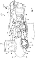
FIG. 2 is a perspective, internal view of a nacelle of a wind turbine according to one embodiment of the present disclosure; -
FIG. 3 is a schematic view of a system for controlling a pitch angle of a rotor blade of a wind turbine according to one embodiment of the present disclosure; -
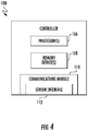
FIG. 4 is a schematic view of a controller of a system for controlling a pitch angle of a rotor blade of a wind turbine according to one embodiment of the present disclosure; and -
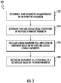
FIG. 5 is a flow chart illustrating a method for controlling a pitch angle of a rotor blade of a wind turbine according to one embodiment of the present disclosure. - Repeat use of reference characters in the present specification and drawings is intended to represent the same or analogous features or elements of the present technology.
- Reference will now be made in detail to present embodiments of the technology, one or more examples of which are illustrated in the accompanying drawings. The detailed description uses numerical and letter designations to refer to features in the drawings. Like or similar designations in the drawings and description have been used to refer to like or similar parts of the technology. As used herein, the terms "first", "second", and "third" may be used interchangeably to distinguish one component from another and are not intended to signify location or importance of the individual components.
- Each example is provided by way of explanation of the technology, not limitation of the technology. In fact, it will be apparent to those skilled in the art that modifications and variations can be made in the present technology without departing from the scope or spirit thereof. For instance, features illustrated or described as part of one embodiment may be used on another embodiment to yield a still further embodiment. Thus, it is intended that the present technology covers such modifications and variations as come within the scope of the appended claims and their equivalents.
- Referring now to the drawings,
FIG. 1 is a perspective view of one embodiment of anexemplary wind turbine 10. As shown, thewind turbine 10 generally includes atower 12 extending from asupport surface 14, anacelle 16 mounted on thetower 12, and arotor 18 coupled to thenacelle 16. Therotor 18 includes arotatable hub 20 and at least onerotor blade 22 coupled to and extending outwardly from thehub 20. For example, in the embodiment shown inFIG. 1 , therotor 18 includes threerotor blades 22. In alternative embodiments, however, therotor 18 may include more or less than threerotor blades 22. Eachrotor blade 22 may be spaced about thehub 20 to facilitate rotating therotor 18 to convert kinetic energy from the wind into usable rotational, mechanical energy. Agenerator 24 positioned in thenacelle 16 may generate electrical power from the rotational energy of therotor 18. - Referring now to
FIG. 2 , adrivetrain 26 rotatably couples therotor 18 to theelectric generator 24. As shown, thedrivetrain 26 may include arotor shaft 28, which rotatably couples thehub 20 of therotor 18 to agearbox 30. Thegearbox 30 may be supported by and coupled to abedplate 32 in thenacelle 16. Thedrivetrain 26 may also include agenerator shaft 34, which rotatably couples thegearbox 30 to thegenerator 24. In this respect, rotation of therotor 18 drives thegenerator 24. More specifically, therotor shaft 28 may provide a low speed, high torque input to thegearbox 30 in response to rotation of therotor blades 22 and thehub 20. Thegearbox 30 may then convert the low speed, high torque input into a high speed, low torque output to drive thegenerator shaft 34 and, thus, thegenerator 24. In alternate embodiments, however, thegenerator 24 may be directly rotatably coupled to therotor shaft 28 in a direct-drive configuration. - The
wind turbine 10 may also include one or morepitch adjustment mechanisms 36. AlthoughFIG. 2 only illustrates onepitch adjustment mechanism 36, thewind turbine 10 may include threepitch adjustment mechanisms 36. In this respect, thewind turbine 10 may include onepitch adjustment mechanism 36 corresponding to eachrotor blade 22. In alternate embodiments, however, thewind turbine 10 may include more or fewerpitch adjustment mechanisms 36. - Each
pitch adjustment mechanism 36 may adjust a pitch angle of the corresponding rotor blade 22 (i.e., the angular orientation of therotor blade 22 with respect to a direction 38 (FIG. 1 ) of the wind). In particular, eachrotor blade 22 may be rotatably coupled to thehub 20 by a pitch bearing (not shown). As such, eachpitch adjustment mechanism 36 may rotate thecorresponding rotor blade 22 about a corresponding pitch axis 40 (FIG. 1 ) relative to thehub 20, thereby adjusting the pitch angle of therotor blade 22. -
FIG. 2 illustrates an exemplary embodiment of one of thepitch adjustment mechanisms 36. More specifically, thepitch adjustment mechanism 36 may include anelectric motor 42 having apinion gear 44 coupled thereto. Thepinion gear 44 may engage aring gear 46 formed on or coupled to an inner surface of therotor blade 22. During operation of thepitch adjustment mechanism 36, theelectric motor 42 rotates thepinion gear 44. Thepinion gear 44, in turn, rotates thering gear 46, thereby rotating therotor blade 22 about thecorresponding pitch axis 40. In alternate embodiments, thepitch adjustment mechanism 36 may include any suitable type of actuator and/or any suitable structure or mechanism for transmitting the movement of the actuator to thecorresponding rotor blade 22. - The
wind turbine 10 may further include various sensors. In the embodiment shown inFIG. 2 , for example, thewind turbine 10 includes apitch angle sensor 48, a rotorblade acceleration sensor 50, a rotorblade deflection sensor 52, a rotorshaft position sensor 54, a rotorshaft deflection sensor 56, and awind speed sensor 58. In alternate embodiments, however, thewind turbine 10 may include only some of thesensors sensors wind turbine 10 may include other sensors in addition to or lieu of thesensors - The
pitch angle sensor 48 detects a pitch angle of thecorresponding rotor blade 22. In this respect, thepitch angle sensor 48 is operatively coupled to one of therotor blades 22 as shown inFIG. 2 . Although only onepitch angle sensor 48 is shown inFIG. 2 , thewind turbine 10 may include onepitch angle sensor 48 operatively coupled to eachrotor blade 22. Thepitch angle sensor 48 may be a Hall Effect sensor or any other suitable type of sensor for detecting absolute or incremental rotational position. - The rotor
blade acceleration sensor 50 detects an acceleration of thecorresponding rotor blade 22. In this respect, the rotorblade acceleration sensor 50 is operatively coupled to one of therotor blades 22 as shown inFIG. 2 . Although only one rotorblade acceleration sensor 50 is shown inFIG. 2 , thewind turbine 10 may include one rotorblade acceleration sensor 50 operatively coupled to eachrotor blade 22. The rotorblade acceleration sensor 50 may be a micro inertial measurement unit or any other suitable type of sensor for detecting acceleration. - The rotor
blade deflection sensor 52 detects a deflection of one of therotor blade 22, such as a deflection caused by asymmetries in the wind. In this respect, theload sensor 52 maybe operatively coupled to thecorresponding rotor blade 22 as shown inFIG. 2 . Although only one rotorblade deflection sensor 52 is shown inFIG. 2 , thesystem 100 may include one rotorblade deflection sensor 52 operatively coupled to eachrotor blade 22. The rotorblade deflection sensor 52 may be a strain gauge, proximity sensor, or any other suitable type of sensor for detecting deflection. - The rotor
shaft position sensor 54 detects a rotational position of therotor shaft 28. In some embodiments, the rotational position of therotor shaft 28 may be used to determine the rotational velocity of therotor blades 22. As shown inFIG. 2 , the rotorshaft position sensor 54 is operatively coupled to arotor shaft 28. The rotorshaft position sensor 54 may be a Hall Effect sensor or any other suitable type of sensor for detecting absolute or incremental rotational position. - The rotor
shaft deflection sensor 56 detects a deflection of therotor shaft 28, such as a deflection caused by an asymmetry in the wind. In this respect, the rotorshaft deflection sensor 56 may be operatively coupled to therotor shaft 28 as shown inFIG. 2 . The rotorshaft deflection sensor 56 may be a strain gauge, proximity sensor, or any other suitable type of sensor for detecting the deflection. - The
wind speed sensor 58 detects a speed of the wind experienced by thewind turbine 10. In the embodiment inFIG. 2 , thewind speed sensor 58 is mounted to the exterior of thenacelle 16. As such, thewind speed sensor 58 maybe a suitable anemometer or a wind vane. In alternate embodiments, however, thewind speed sensor 58 may be a light detection and ranging (LIDAR) sensor, an ultrasonic sensor, or any other suitable type of sensor for detecting wind velocity. In some embodiments, thewind turbine 10 may include a plurality ofwind speed sensors 58 to detect the speed of the wind at different locations, such as two vertically spaced apart anemometers. In further embodiments, thewind speed sensor 58 may be separate from thewind turbine 10, such as a wind speed measurement tower for a wind turbine farm. -
FIG. 3 illustrates asystem 100 for controlling the pitch angle of therotor blades 22 of thewind turbine 10. As mentioned above, asymmetries in the wind may cause load imbalances on certain components of thewind turbine 10. As will be discussed in greater detail below, thesystem 100 controls the pitch angle of therotor blades 22 to distribute the wear caused by these load imbalances across various components of thewind turbine 10. - As shown, the
system 100 may include asensor 102 for detecting an operating parameter of thewind turbine 10. The operating parameter may be associated with or is indicative an asymmetry in the wind experienced by thewind turbine 10. For example, the operating parameter may be a pitch angle of one or more of therotor blades 22, an acceleration of one or more of therotor blades 22, a deflection of one or more of therotor blades 22, a position or speed of therotor shaft 28, a deflection of therotor shaft 28, or a speed (or variation in the speed) of the wind experienced by thewind turbine 10. In this respect, thesensor 102 may correspond to the pitch angle sensor(s) 48, the rotor blade acceleration sensor(s) 50, the rotor blade deflection sensor(s) 52, the rotorshaft position sensor 54, the rotorshaft deflection sensor 56, or the wind speed sensor(s) 58. Although only onesensor 102 is shown inFIG. 3 , thesystem 100 may includemore sensors 102, such as two vertically spaced apartwind speed sensors 58 for detecting a speed of the wind at different locations. In alternate embodiments, thesensor 102 may correspond to sensors not shown inFIG. 2 . Furthermore, the operating parameter may be any suitable parameter that corresponds to a current condition within thewind turbine 10 or an environmental condition experienced by thewind turbine 10. - The
system 100 also includes acontroller 104 communicatively coupled to one or more components of thesystem 100 and/or thewind turbine 10, such as the sensor(s) 102 and thepitch adjustment mechanisms 36. In the embodiment shown inFIG. 2 , for example, thecontroller 104 is disposed within acontrol cabinet 60 mounted to a portion of thenacelle 16. In alternate embodiments, however, thecontroller 104 may be disposed at any location on or in thewind turbine 10, at any location on thesupport surface 14, or any other suitable location. - In general, the
controller 104 may correspond to any suitable processor-based device, including one or more computing devices. As shown inFIG. 4 , for example, thecontroller 104 may include one ormore processors 106 and one or more associatedmemory devices 108 configured to perform a variety of computer-implemented functions (e.g., performing the methods, steps, calculations, and the like disclosed herein). As used herein, the term "processor" refers not only to integrated circuits referred to in the art as being included in a computer, but also refers to a controller, microcontroller, a microcomputer, a programmable logic controller (PLC), an application specific integrated circuit (ASIC), a Field Programmable Gate Array (FPGA), and other programmable circuits. Additionally, the memory device(s) 108 may generally include memory element(s) including, but not limited to, a computer readable medium (e.g., random access memory (RAM)), a computer readable nonvolatile medium (e.g., flash memory), a compact disc-read only memory (CD-ROM), a magneto-optical disk (MOD), a digital versatile disc (DVD), and/or other suitable memory elements or combinations thereof. The memory device(s) 108 may store instructions that, when executed by theprocessor 106, cause theprocessor 106 to perform functions (e.g.,method 200 described below). - The
controller 104 may also include acommunications module 110 to facilitate communications between thecontroller 104 and the various components of thesystem 100 and/or thewind turbine 10. For example, thecommunications module 110 may permit thecontroller 104 to receive data from thesensor 102. As such, thecommunications module 110 may include a sensor interface 112 (e.g., one or more analog-to-digital converters) that converts measurement signals 116 received from thesensor 102 into signals that can be understood and processed by theprocessors 106. Furthermore, thecommunications module 110 may permit thecontroller 104 to transmitcontrol signals 118 to eachpitch adjustment mechanism 36 for controlling the pitch angle of therotor blades 22. In this respect, thecommunications module 110 may be any combination of suitable wired and/or wireless communication interfaces that communicatively couple thesensor 102 and thepitch adjustment mechanisms 36 to thecontroller 110. - As mentioned above, the
system 100 controls the pitch angles of therotor blades 22 during operation of thewind turbine 10. More specifically, the asymmetries in the wind (e.g., caused by wind shear, up-flow, nearby wind turbines, turbulence, etc.) may cause load imbalances on certain components of the wind turbine 10 (e.g., the rotor blades 22), thereby causing these components to incur wear. However, adjusting the pitch angles of therotor blades 22 to minimize these load imbalances may cause other components (e.g., the pitch adjustment mechanisms 36) to incur wear. In this respect, thesystem 100 may control the pitch angles of therotor blades 22 in a manner that distributes the wear across various components of thewind turbine 10. For example, thesystem 100 may adjust the pitch angles of therotor blades 22 to prevent the wind asymmetries from exerting large loads on therotor blades 22, while minimizing the distance that thepitch adjustment mechanisms 36 must move therotor blades 22. - The
system 100 will be described below in the context of distributing wear between therotor blades 22 and the correspondingpitch adjustment mechanisms 36. However, thesystem 100 may be used to distribute wear between any component of thewind turbine 10 that may experience a load imbalance due to a wind asymmetry (e.g., thetower 12, thenacelle 16, therotor shaft 28, thegearbox 30, one of the pitch bearings (not shown), or a yaw bearing (not shown)) and any actuator of the wind turbine 10 (e.g., a yaw adjustment system (not shown)). - Referring again to
FIG. 3 , thecontroller 104 may be configured to control thepitch adjustment mechanisms 36 by executing various logic stored on the memory device(s) 108. In particular, the controller 104 (e.g., via the processor(s) 106) executes the logic to create the control signals 116 based the data received from thesensor 102 and/or data stored in the memory device(s) 108. Using the control signals 116, thepitch adjustment mechanisms 36 adjust the pitch angles of thecorresponding rotor blades 22 to distribute the wear caused by the load imbalances across various components (e.g., between therotor blades 22 and the pitch adjustment mechanisms 36) of thewind turbine 10. Thecontroller 104 may control eachpitch adjustment mechanism 36 individually (i.e., the control signals 116 may be different for each pitch adjustment mechanism 36) in some embodiments. In alternate embodiments, however, thecontroller 104 may control all ofpitch adjustment mechanisms 36 as a collective unit (i.e., the control signals 116 may be the same for each pitch adjustment mechanism 36). - The
controller 104 may be configured to determine a wind asymmetry parameter. As mentioned above, thecontroller 104 is communicatively coupled to thesensor 102. In this respect, thecontroller 104 receives the measurement signals 118 indicative of the operating parameter of thewind turbine 10 from thesensor 102. In embodiments of thesystem 100 that include more than onesensor 102, thecontroller 104 may receiveadditional measurement signals 118 indicative of other operating parameters from theadditional sensors 102. As shown inFIG. 3 , thecontroller 104 may include windasymmetry parameter logic 120 having one or more mathematical functions and/or one or more look-up tables. By executing the windasymmetry parameter logic 120, thecontroller 110 may generate a windasymmetry parameter signal 122 indicative of the wind asymmetry parameter based on the measurement signal(s) 118 received by thecontroller 104 and/orwind turbine data 124 stored in the memory device(s) 108. The wind asymmetry parameter may be any parameter associated with or indicative of an asymmetry in the wind experienced by thewind turbine 10. In particular, the wind asymmetry parameter may be associated with any asymmetry in the wind around therotor 18, including slow-varying asymmetries, such wind up flow, wind shear, wind veer, and wind direction, and fast-varying asymmetries, such as wind turbulence and wind gust. For example, the wind asymmetry parameter may be a difference in the magnitudes and/or directions of the wind speed detected at different positions on thewind turbine 10, a difference in the deflections and/or accelerations of therotor blades 22, or a magnitude and/or a direction of a deflection of therotor shaft 28. Thewind turbine data 124 may include any predetermined parameters, values, or other data useful in determining the wind asymmetry parameter, such as a distance between two of thesensors 102. In some embodiments, thewind turbine data 124 may not be used to determine the wind asymmetry parameter. In alternate embodiments, the windasymmetry parameter logic 120 may use any suitable methodology or criteria to determine the wind asymmetry parameter. - The
controller 104 may also be configured to determine first andsecond signal components asymmetry parameter signal 122. In this respect, thecontroller 104 may includesignal component logic 126 having one or more mathematical functions and/or one or more look-up tables. By executing thesignal component logic 126, thecontroller 104 may determine the first andsecond signal components asymmetry parameter signal 122. In some embodiments, thesignal component logic 126 may include one or more filters (e.g., low-pass filters, high-pass filters, band-pass filters, etc.) that filter the windasymmetry parameter signal 122 to determine the first and/orsecond signal components first signal component 128 may be associated with or indicative of an estimated maximum load exerted on therotor blades 22 due to the wind asymmetry. Conversely, thesecond signal component 130 is associated with or indicative of an estimated fatigue on thepitch adjustment mechanisms 36 when thepitch adjustment mechanisms 36 adjust the pitch angles of the rotor balances to mitigate the load imbalance. In this respect, the first and second signal components may be one or more low pass components, band pass components, high pass components, notch components, spectral magnitude components, or phase components. For example, thefirst signal component 128 may be a weighted combination of low frequency and high frequency spectral amplitudes of the windasymmetry parameter signal 122. Thesecond signal component 130 may be a filtered magnitude, a spectral component, or a phase component of the windasymmetry parameter signal 122. In some embodiments, each of the first and/orsecond signal components asymmetry parameter signal 122 or a combination of signal components of the windasymmetry parameter signal 122. In alternate embodiments, thesignal component logic 126 may use any suitable methodology or criteria to determine the wind asymmetry parameter. - The
controller 104 may further be configured to calculate a wear parameter for therotor blade 22 andpitch adjustment mechanism 36 based on the first andsecond signal components controller 104 may include wearparameter logic 132 having one or more mathematical functions. By executing thewear parameter logic 132, thecontroller 104 may generate awear parameter signal 134 indicative of the wear parameter based on the first andsecond signal component second signal components rotor blades 22 and/or thepitch adjustment mechanisms 36. In alternate embodiments, thewear parameter logic 132 may use any suitable methodology or criteria to determine the wind asymmetry parameter. - The
controller 104 may use the wear parameter to distribute the wear between therotor blades 22 andpitch adjustment mechanisms 36. In this respect, the wear parameter is associated with or indicative of a comparison between the estimated wear on therotor blades 22 if therotor blades 22 were to endure the load imbalance caused by the wind asymmetry and the estimated wear on thepitch adjustment mechanisms 36 if thepitch adjustment mechanism 36 were to adjust the pitch angle of therotor blade 22 to minimize the load on therotor blade 22. In some embodiments, the wear parameter is based on additional parameters, such as the value and/or the replacement difficulty of therotor blades 22 andpitch adjustment mechanisms 36. As such, the wear parameter may be representative of whether thesystem 100 should allow therotor blade 22 to endure the load imbalance or adjust the pitch angle of therotor blade 22 to minimize the load imbalance. Although the wear parameter is described above in the context of therotor blades 22 andpitch adjustment mechanisms 36, the wear parameter may be based on any number and/or type of components of thewind turbine 10. - Furthermore, the
controller 104 may be configured to selectively initiate an adjustment of thepitch adjustment mechanisms 36 based on the wear parameter. In this respect, thecontroller 104 may not adjust the pitch angles of therotor blades 22 when the wear parameter indicates that it is desirable for therotor blades 22 to incur the load imbalance caused by the wind asymmetry. Conversely, wear parameter indicates that it is desirable for thepitch adjustment mechanisms 36 to incur wear from adjusting the pitch angles of therotor blades 22, thecontroller 104 may initiate adjustment of thepitch adjustment mechanisms 36. As mentioned above, thecontroller 104 is communicatively coupled to thepitch adjustment mechanisms 36. In this respect, thecontroller 104 transmits the control signals 116 indicative of desired pitch angles of therotor blades 22 to the correspondingpitch adjustment mechanism 36. As shown inFIG. 3 , thecontroller 104 may includepitch angle logic 136 having one or more mathematical functions and/or one or more look-up tables. By executing thepitch angle logic 136, thecontroller 110 may generate the controls signals 118 indicative of desired pitch angles of therotor blades 22 based on thewear parameter signal 134. In some embodiments, the control signals 118 may also be based on the first and/orsecond signal component wind turbine data 124, and/or the measurement signals 116 from sensor(s) 102. Based on the control signals 116, thepitch adjustment mechanisms 36 adjust the pitch angles of therotor blades 22 to desired pitch angle. For example, when the wear parameter indicates that it is desirable to adjust the pitch angles of therotor blades 22 to mitigate the load imbalance thereon, the control signals 118 may instruct thepitch adjustment mechanisms 36 to make the desired adjustments. Conversely, when the wear parameter indicates that it is desirable for therotor blades 22 to endure the loads thereon, the control signals 118 may instruct thepitch adjustment mechanisms 36 to maintain the current pitch angles of therotor blades 22. - In some embodiments, the
pitch angle logic 136 may include various mathematical functions to optimize the adjustment of the pitch angles of therotor blades 22. For example, thepitch angle logic 36 may include a dead band range. In this respect, thecontroller 104 may be configured to compare the wear parameter to the dead band range. As such, thecontroller 104 may be configured to transmitcontrol signals 118 to thepitch adjustment mechanisms 36 that instruct thepitch adjustment mechanisms 36 to adjust the pitch angles of therotor blades 22 only when the wear parameter falls outside of the dead band range. In further embodiments, thepitch angle logic 136 may also include an inequality comparison, a hysteresis band, linear functions, and/or non-linear functions. - FIG. 6 illustrates a
method 200 for controlling the pitch angles of therotor blades 22 of thewind turbine 10 in accordance with embodiments of the present disclosure. - In
step 202, the wind asymmetry parameter is determined based on an operating parameter. For example, thesensor 102 may detect an operating parameter of thewind turbine 10. In this respect, thecontroller 104 may receive the measurement signals 118 indicative of the operating parameter from thesensor 102. Thecontroller 104 may then execute logic (e.g., the wind asymmetry parameter logic 120) to generate the windasymmetry parameter signal 22 based on the measurement signals 118 and/or thewind turbine data 124. As discussed in greater detail above, the logic may include one or more look-up tables and/or one or more mathematical functions. - In
step 204, the first andsecond signal components controller 104 may then execute logic (e.g., the signal component logic 126) to generate the first andsecond signal component asymmetry parameter signal 122. As discussed in greater detail above, the logic may include one or more look-up tables and/or one or more mathematical functions. In some embodiments, the logic may include one or more filters. - In
step 206, the wear parameter is calculated from the first andsecond signal components controller 104 may then execute logic (e.g., the wear parameter logic 132) to generate thewear parameter signal 134 based on the first andsecond signal component - In
step 208, pitch angle adjustments of therotor blades 22 are selectively initiated based on the wear parameter. As described above, thecontroller 104 may be configured to determine whether to initiate an adjustment of the pitch angles of therotor blades 22 based on the wear parameter. When the wear parameter indicates that an adjustment of the pitch angles of therotor blades 22 is desirable, thecontroller 104 may then execute logic (e.g., the pitch angle logic 136) to generate the control signals 116 based on thewear parameter signal 134. In some embodiments, the control signals 116 may be also based on the first andsecond signal component wind turbine data 124, and/or the measurement signals 118. Furthermore, thecontroller 104 may compare the wear parameter to a dead band range and initiate an adjustment of the pitch angles of therotor blades 22 when the wear parameter falls outside of the dead band range. As discussed in greater detail above, the logic may include one or more look-up tables and/or one or more mathematical functions. - As discussed above, the
system 100 and themethod 200 distribute wear caused by wind asymmetries between various components of thewind turbine 10 based on the wear parameter. In this respect, and unlike conventional systems and methods, the wear is not concentrated on particular components of thewind turbine 10, thereby increasing the service life of these components (e.g., therotor blades 22, the pitch adjustment mechanisms, etc.) and thewind turbine 10. - This written description uses examples to disclose the technology, including the preferred mode, and also to enable any person skilled in the art to practice the technology, including making and using any devices or systems and performing any incorporated methods. The patentable scope of the technology is defined by the claims, and may include other examples that occur to those skilled in the art. Such other examples are intended to be within the scope of the claims if they include structural elements that do not differ from the literal language of the claims, or if they include equivalent structural elements with insubstantial differences from the literal language of the claims.
- Various aspects and embodiments of the present invention are defined by the following numbered clauses:
- 1. A system for controlling a pitch angle of a rotor blade of a wind turbine, the system comprising:
- a rotor including a hub and a rotor blade;
- a pitch adjustment mechanism for adjusting the pitch angle of the rotor blade by rotating the rotor blade about a pitch axis relative to the hub; and
- a controller communicatively coupled to the pitch adjustment mechanism, the controller configured to:
- determine a wind asymmetry parameter based on an operating parameter of the wind turbine, the wind asymmetry parameter being indicative of an asymmetry in the wind experienced by the wind turbine;
- determine first and second signal components of the wind asymmetry parameter, the first signal component being indicative of a maximum load on a first wind turbine component, the second signal component being indicative of fatigue on a second wind turbine component;
- calculate a wear parameter for the first and second wind turbine components based on the first and second signal components; and
- initiate an adjustment of the pitch angle of the rotor blade based on the wear parameter.
- 2. The system of clause 1, wherein the wind turbine asymmetry parameter is associated with wind up flow, wind shear, wind veer, wind direction, wind turbulence, or wind gust.
- 3. The system of any preceding clause, wherein the pitch adjustment mechanism is further controlled to adjust the pitch angle of the rotor blade based on the first or second signal component.
- 4. The system of any preceding clause, further comprising:
a sensor communicatively coupled to the controller, the sensor being configured to detect the operating parameter of the wind turbine. - 5. The system of any preceding clause, wherein the first component is one a tower, a nacelle, a rotor shaft, or and gearbox and the second component is an actuator.
- 6. The system of any preceding clause, wherein the controller is further configured to filter the wind asymmetry parameter to determine the first and second signal components.
- 7. The system of any preceding clause, wherein the first and second signal components comprise one or more low pass components, band pass components, high pass components, notch components, spectral magnitude components, or phase components.
- 8. The system of any preceding clause, wherein the first signal component comprises a weighted combination of a low frequency spectral amplitude of the wind asymmetry parameter and a high frequency spectral amplitude of the wind asymmetry parameter and the second signal component comprises one or more of a filtered magnitude of the wind asymmetry parameter, a spectral component of the wind asymmetry parameter, or a phase component of the wind asymmetry parameter.
- 9. The system of any preceding clause, wherein the controller is further configured to compare the wear parameter to a dead band range and initiate an adjustment of the pitch angle of the rotor blade when the wear parameter falls outside of the dead band range.
- 10. A method for controlling a pitch angle of a rotor blade of a wind turbine, the method comprising:
- determining, with a controller, a wind asymmetry parameter based on an operating parameter of the wind turbine, the wind asymmetry parameter being indicative of an asymmetry in the wind experienced by the wind turbine;
- determining, with the controller, first and second signal components of the wind asymmetry parameter, the first signal component being indicative of a maximum load on a first wind turbine component, the second signal component being indicative of fatigue on a second wind turbine component;
- calculating, with the controller, a wear parameter for the first and second wind turbine components based on the first and second signal components; and determining, with the controller, an adjustment of the pitch angle of the rotor blade based on the wear parameter.
- 11. The method of any preceding clause, wherein the wind turbine asymmetry parameter is associated with wind up flow, wind shear, wind veer, wind direction, wind turbulence, or wind gust.
- 12. The method of any preceding clause, further comprising:
adjusting, with the actuator, the pitch angle of the rotor blade based on the first and second signal components. - 13. The method of any preceding clause, further comprising:
detecting, with a sensor communicatively coupled to the controller, the operating parameter of the wind turbine. - 14. The method of any preceding clause, further comprising:
detecting, with the sensor, a deflection of a rotor shaft of the wind turbine. - 15. The method of any preceding clause, wherein the first component is one a tower, a nacelle, a rotor shaft, or and gearbox and the second component is an actuator.
- 16. The method of any preceding clause, further comprising:
filtering, with the controller, the wind asymmetry parameter to determine the first and second signal components. - 17. The method of any preceding clause, wherein the first and second signal components comprise one or more low pass components, band pass components, high pass components, notch components, spectral magnitude components, or phase components.
- 18. The method of any preceding clause, wherein the first signal component comprises a weighted combination of a low frequency spectral amplitude of the wind asymmetry parameter and a high frequency spectral amplitude of the wind asymmetry parameter and the second signal component comprises one of more of a filtered magnitude of the wind asymmetry parameter, a spectral component of the wind asymmetry parameter, or a phase component of the wind asymmetry parameter.
- 19. The method of any preceding clause, further comprising:
comparing, with the controller, the wear parameter to a dead band range; and initiating, with the controller, an adjustment of the pitch angle of the rotor blade when the wear parameter falls outside of the dead band range. - 20. A method for controlling a pitch angle of a rotor blade of a wind turbine, the method comprising:
- determining, with a controller, a wind asymmetry parameter based on an operating parameter of the wind turbine, the wind asymmetry parameter being indicative of an asymmetry in the wind experienced by the wind turbine;
- determining, with the controller, first and second signal components of the wind asymmetry parameter, the first signal component being indicative of a maximum load on the rotor blade, the second signal component being indicative of fatigue on a pitch adjustment mechanism;
- calculating, with the controller, a wear parameter for the rotor blade and the pitch adjustment mechanism based on the first and second signal components; and determining, with the controller, an adjustment of the pitch angle of the rotor blade based on the wear parameter.
Claims (15)
- A system (100) for controlling a pitch angle of a rotor blade (22) of a wind turbine (10), the system comprising:a rotor including a hub and a rotor blade (22);a pitch adjustment mechanism (36) for adjusting the pitch angle of the rotor blade (22) by rotating the rotor blade about a pitch axis relative to the hub; anda controller (104) communicatively coupled to the pitch adjustment mechanism, the controller configured to:determine a wind asymmetry parameter based on an operating parameter of the wind turbine (10), the wind asymmetry parameter being indicative of an asymmetry in the wind experienced by the wind turbine;determine first and second signal components (128,130) of the wind asymmetry parameter, the first signal component (128) being indicative of a maximum load on a first wind turbine component, the second signal component (130) being indicative of fatigue on a second wind turbine component;calculate a wear parameter for the first and second wind turbine components based on the first and second signal components (128,130); andinitiate an adjustment of the pitch angle of the rotor blade (22) based on the wear parameter.
- The system (100) of claim 1, wherein the wind turbine asymmetry parameter is associated with wind up flow, wind shear, wind veer, wind direction, wind turbulence, or wind gust.
- The system (100) of any preceding claim, wherein the pitch adjustment mechanism (36) is further controlled to adjust the pitch angle of the rotor blade (22) based on the first or second signal component.
- The system (100) of any preceding claim, further comprising:
a sensor (54,56,58) communicatively coupled to the controller (104), the sensor being configured to detect the operating parameter of the wind turbine. - The system (100) of any preceding claim, wherein the first component is one a tower (12), a nacelle (16), a rotor shaft (28), or and gearbox (30) and the second component is an actuator.
- The system (100) of any preceding claim, wherein the controller (104) is further configured to filter the wind asymmetry parameter to determine the first and second signal components.
- The system (100) of any preceding claim, wherein the first and second signal components (128,130) comprise one or more low pass components, band pass components, high pass components, notch components, spectral magnitude components, or phase components.
- The system (100) of any preceding claim, wherein the first signal component (128) comprises a weighted combination of a low frequency spectral amplitude of the wind asymmetry parameter and a high frequency spectral amplitude of the wind asymmetry parameter and the second signal component (130) comprises one or more of a filtered magnitude of the wind asymmetry parameter, a spectral component of the wind asymmetry parameter, or a phase component of the wind asymmetry parameter.
- The system (100) of any preceding claim, wherein the controller (104) is further configured to compare the wear parameter to a dead band range and initiate an adjustment of the pitch angle of the rotor blade (22) when the wear parameter falls outside of the dead band range.
- A method (200) for controlling a pitch angle of a rotor blade (22) of a wind turbine (10), the method comprising:determining (202), with a controller, a wind asymmetry parameter based on an operating parameter of the wind turbine (10), the wind asymmetry parameter being indicative of an asymmetry in the wind experienced by the wind turbine (10);determining (204), with the controller (104), first and second signal components (128,130) of the wind asymmetry parameter, the first signal component being indicative of a maximum load on a first wind turbine component (128), the second signal component (130) being indicative of fatigue on a second wind turbine component;calculating (206), with the controller (104), a wear parameter for the first and second wind turbine components based on the first and second signal components; anddetermining, with the controller (104), an adjustment of the pitch angle of the rotor blade (22) based on the wear parameter.
- The method (200) of claim 10, wherein the wind turbine asymmetry parameter is associated with wind up flow, wind shear, wind veer, wind direction, wind turbulence, or wind gust.
- The method (200) of claim 10 or claim 11, further comprising:
adjusting (208), with the actuator, the pitch angle of the rotor blade (22) based on the first and second signal components. - The method (200) of any of claims 10 to 12, further comprising:
detecting, with a sensor (54,56,58) communicatively coupled to the controller (104), the operating parameter of the wind turbine (10). - The method (200) of claim 13, further comprising:
detecting, with the sensor (54,56,58), a deflection of a rotor shaft (28) of the wind turbine (10). - The method (200) of any of claims 10 to 14, further comprising:
filtering, with the controller (104), the wind asymmetry parameter to determine the first and second signal components (128,130).
Applications Claiming Priority (1)
| Application Number | Priority Date | Filing Date | Title |
|---|---|---|---|
| IN201741017483 | 2017-05-18 |
Publications (2)
| Publication Number | Publication Date |
|---|---|
| EP3404257A1 true EP3404257A1 (en) | 2018-11-21 |
| EP3404257B1 EP3404257B1 (en) | 2021-11-17 |
Family
ID=62152376
Family Applications (1)
| Application Number | Title | Priority Date | Filing Date |
|---|---|---|---|
| EP18171680.4A Active EP3404257B1 (en) | 2017-05-18 | 2018-05-10 | System and method for controlling a pitch angle of a wind turbine rotor blade |
Country Status (4)
| Country | Link |
|---|---|
| US (1) | US10781792B2 (en) |
| EP (1) | EP3404257B1 (en) |
| DK (1) | DK3404257T3 (en) |
| ES (1) | ES2906872T3 (en) |
Cited By (1)
| Publication number | Priority date | Publication date | Assignee | Title |
|---|---|---|---|---|
| CN113217278A (en) * | 2020-02-06 | 2021-08-06 | 通用电气公司 | Controlling wind turbine pitch based on position data from position location sensors |
Families Citing this family (3)
| Publication number | Priority date | Publication date | Assignee | Title |
|---|---|---|---|---|
| US11293403B2 (en) * | 2019-04-09 | 2022-04-05 | General Electric Company | System and method for preventing catastrophic damage in drivetrain of a wind turbine |
| CN113390376B (en) * | 2020-03-13 | 2023-04-07 | 新疆金风科技股份有限公司 | Method, device and system for determining cabin displacement of wind generating set |
| CN112761872B (en) * | 2021-01-25 | 2022-11-01 | 三一重能股份有限公司 | Wind power variable pitch overspeed protection method and device and wind power variable pitch system |
Citations (3)
| Publication number | Priority date | Publication date | Assignee | Title |
|---|---|---|---|---|
| EP2302207A1 (en) * | 2009-09-23 | 2011-03-30 | Siemens Aktiengesellschaft | Power generating machine load control based on consumed fatigue life time and real-time of operation of a structural component |
| US20150132128A1 (en) * | 2012-06-06 | 2015-05-14 | Vestas Wind Systems A/S | Wind turbine with a load controller |
| EP3015705A1 (en) * | 2014-10-27 | 2016-05-04 | General Electric Company | System and method for adaptive rotor imbalance control |
Family Cites Families (20)
| Publication number | Priority date | Publication date | Assignee | Title |
|---|---|---|---|---|
| DE19731918B4 (en) | 1997-07-25 | 2005-12-22 | Wobben, Aloys, Dipl.-Ing. | Wind turbine |
| EP1994281B1 (en) | 2006-03-16 | 2013-05-22 | Vestas Wind Systems A/S | A method and control system for reducing the fatigue loads in the components of a wind turbine subjected to asymmetrical loading of the rotor plane |
| CN101523048B (en) | 2006-10-02 | 2012-05-30 | 剪式风能公司 | Wind turbine with blade pitch control to compensate for wind shear and wind misalignment |
| JP4994947B2 (en) | 2007-05-21 | 2012-08-08 | 三菱重工業株式会社 | Wind power generator and yaw rotation drive method for wind power generator |
| ES2656542T3 (en) | 2007-08-31 | 2018-02-27 | Vestas Wind Systems A/S | Method for the control of at least one regulation mechanism of a wind turbine, a wind turbine and a wind farm |
| ES2723877T3 (en) * | 2007-11-15 | 2019-09-03 | Siemens Gamesa Renewable Energy Innovation & Technology SL | Method and system for the operation of a wind turbine |
| WO2009129617A1 (en) | 2008-04-24 | 2009-10-29 | Mike Jeffrey | A method and system for determining an imbalance of a wind turbine rotor |
| NL2001878C2 (en) | 2008-08-07 | 2010-02-09 | Stichting Energie | System and method for compensating rotor imbalance for a wind turbine. |
| US8430634B2 (en) | 2010-02-03 | 2013-04-30 | Herbert Williams | System and method for improving wind turbine efficiency by adjusting blade pitch in response to localized wind speed |
| ES2398020B1 (en) | 2011-03-17 | 2014-09-05 | Gamesa Innovation & Technology, S.L. | METHODS AND SYSTEMS TO RELIEF THE LOADS PRODUCED IN AEROGENERATORS BY THE WIND ASYMETRIES. |
| US20120134813A1 (en) | 2011-12-13 | 2012-05-31 | Jacob Johannes Nies | Active flow control system and method for operating the system to reduce imbalance |
| CN104428531B (en) * | 2012-06-08 | 2018-05-22 | 维斯塔斯风力系统集团公司 | Method of operating a wind turbine and system suitable for said method |
| ES2751687T3 (en) * | 2013-10-07 | 2020-04-01 | Vestas Wind Sys As | Methods and apparatus for controlling wind turbines |
| ES2538739B1 (en) | 2013-12-23 | 2016-04-14 | Acciona Windpower, S.A. | Wind Turbine Control Method |
| US9745958B2 (en) * | 2014-06-30 | 2017-08-29 | General Electric Company | Method and system for managing loads on a wind turbine |
| CN107076114B (en) | 2014-08-13 | 2019-08-27 | 维斯塔斯风力系统集团公司 | Improvements related to determining rotor imbalance in wind turbines |
| EP3189231B1 (en) | 2014-09-01 | 2020-01-01 | Vestas Wind Systems A/S | Improvements relating to the determination of rotor imbalances in a wind turbine |
| DE102014225637A1 (en) | 2014-12-12 | 2016-06-30 | Robert Bosch Gmbh | Method and device for monitoring a wind energy plant |
| JP6314104B2 (en) | 2015-03-04 | 2018-04-18 | 三菱重工業株式会社 | Wind power generation facility and control method for wind power generation facility |
| CN107667221B (en) | 2015-04-23 | 2019-11-05 | 远景能源(江苏)有限公司 | Method for correcting rotor unbalance and wind turbine therefor |
-
2018
- 2018-05-09 US US15/974,744 patent/US10781792B2/en active Active
- 2018-05-10 EP EP18171680.4A patent/EP3404257B1/en active Active
- 2018-05-10 ES ES18171680T patent/ES2906872T3/en active Active
- 2018-05-10 DK DK18171680.4T patent/DK3404257T3/en active
Patent Citations (3)
| Publication number | Priority date | Publication date | Assignee | Title |
|---|---|---|---|---|
| EP2302207A1 (en) * | 2009-09-23 | 2011-03-30 | Siemens Aktiengesellschaft | Power generating machine load control based on consumed fatigue life time and real-time of operation of a structural component |
| US20150132128A1 (en) * | 2012-06-06 | 2015-05-14 | Vestas Wind Systems A/S | Wind turbine with a load controller |
| EP3015705A1 (en) * | 2014-10-27 | 2016-05-04 | General Electric Company | System and method for adaptive rotor imbalance control |
Non-Patent Citations (1)
| Title |
|---|
| VALI MEHDI ET AL: "Optimal multivariable individual pitch control for load reduction of large wind turbines", 2016 AMERICAN CONTROL CONFERENCE (ACC), AMERICAN AUTOMATIC CONTROL COUNCIL (AACC), 6 July 2016 (2016-07-06), pages 3163 - 3169, XP032933167, DOI: 10.1109/ACC.2016.7525404 * |
Cited By (1)
| Publication number | Priority date | Publication date | Assignee | Title |
|---|---|---|---|---|
| CN113217278A (en) * | 2020-02-06 | 2021-08-06 | 通用电气公司 | Controlling wind turbine pitch based on position data from position location sensors |
Also Published As
| Publication number | Publication date |
|---|---|
| US10781792B2 (en) | 2020-09-22 |
| EP3404257B1 (en) | 2021-11-17 |
| US20180335016A1 (en) | 2018-11-22 |
| ES2906872T3 (en) | 2022-04-20 |
| DK3404257T3 (en) | 2022-02-14 |
Similar Documents
| Publication | Publication Date | Title |
|---|---|---|
| EP3483433B1 (en) | Method and system for detecting a mass imbalance in a wind turbine rotor | |
| DK2933477T3 (en) | SYSTEM AND PROCEDURE FOR PRESSURE SPEED CONTROL OF A WINDMILL | |
| US7772713B2 (en) | Method and system for controlling a wind turbine | |
| DK177188B1 (en) | Method and apparatus for controlling the tip speed of a blade of a wind turbine | |
| CA2810157C (en) | Method of rotor-stall prevention in wind turbines | |
| EP2981710B1 (en) | Method for controlling thrust load on a wind turbine | |
| EP3619423B1 (en) | System and method for reducing wind turbine rotor blade loads | |
| EP2757256A2 (en) | Wind turbine and method for adjusting rotor blade pitch angle in wind turbines | |
| US11867150B2 (en) | Azimuth sensors in wind turbines | |
| US10781792B2 (en) | System and method for controlling a pitch angle of a wind turbine rotor blade | |
| WO2016077183A1 (en) | System and method for estimating rotor blade loads of a wind turbine | |
| US10240581B2 (en) | System and method for controlling pitch angle of a wind turbine rotor blade | |
| EP3892850B1 (en) | System and method for mitigating loads acting on a rotor blade of a wind turbine | |
| EP3788257A1 (en) | System and method for controlling pitch angle of a wind turbine rotor blade | |
| KR20250046196A (en) | Methods for estimating values of wind turbine operational parameters |
Legal Events
| Date | Code | Title | Description |
|---|---|---|---|
| PUAI | Public reference made under article 153(3) epc to a published international application that has entered the european phase |
Free format text: ORIGINAL CODE: 0009012 |
|
| STAA | Information on the status of an ep patent application or granted ep patent |
Free format text: STATUS: THE APPLICATION HAS BEEN PUBLISHED |
|
| AK | Designated contracting states |
Kind code of ref document: A1 Designated state(s): AL AT BE BG CH CY CZ DE DK EE ES FI FR GB GR HR HU IE IS IT LI LT LU LV MC MK MT NL NO PL PT RO RS SE SI SK SM TR |
|
| AX | Request for extension of the european patent |
Extension state: BA ME |
|
| STAA | Information on the status of an ep patent application or granted ep patent |
Free format text: STATUS: REQUEST FOR EXAMINATION WAS MADE |
|
| 17P | Request for examination filed |
Effective date: 20190521 |
|
| RBV | Designated contracting states (corrected) |
Designated state(s): AL AT BE BG CH CY CZ DE DK EE ES FI FR GB GR HR HU IE IS IT LI LT LU LV MC MK MT NL NO PL PT RO RS SE SI SK SM TR |
|
| STAA | Information on the status of an ep patent application or granted ep patent |
Free format text: STATUS: EXAMINATION IS IN PROGRESS |
|
| 17Q | First examination report despatched |
Effective date: 20201008 |
|
| GRAP | Despatch of communication of intention to grant a patent |
Free format text: ORIGINAL CODE: EPIDOSNIGR1 |
|
| STAA | Information on the status of an ep patent application or granted ep patent |
Free format text: STATUS: GRANT OF PATENT IS INTENDED |
|
| INTG | Intention to grant announced |
Effective date: 20210615 |
|
| GRAS | Grant fee paid |
Free format text: ORIGINAL CODE: EPIDOSNIGR3 |
|
| GRAA | (expected) grant |
Free format text: ORIGINAL CODE: 0009210 |
|
| STAA | Information on the status of an ep patent application or granted ep patent |
Free format text: STATUS: THE PATENT HAS BEEN GRANTED |
|
| AK | Designated contracting states |
Kind code of ref document: B1 Designated state(s): AL AT BE BG CH CY CZ DE DK EE ES FI FR GB GR HR HU IE IS IT LI LT LU LV MC MK MT NL NO PL PT RO RS SE SI SK SM TR |
|
| REG | Reference to a national code |
Ref country code: GB Ref legal event code: FG4D |
|
| REG | Reference to a national code |
Ref country code: IE Ref legal event code: FG4D |
|
| REG | Reference to a national code |
Ref country code: DE Ref legal event code: R096 Ref document number: 602018026710 Country of ref document: DE |
|
| REG | Reference to a national code |
Ref country code: AT Ref legal event code: REF Ref document number: 1448250 Country of ref document: AT Kind code of ref document: T Effective date: 20211215 |
|
| REG | Reference to a national code |
Ref country code: DK Ref legal event code: T3 Effective date: 20220210 |
|
| REG | Reference to a national code |
Ref country code: LT Ref legal event code: MG9D |
|
| REG | Reference to a national code |
Ref country code: NL Ref legal event code: MP Effective date: 20211117 |
|
| REG | Reference to a national code |
Ref country code: AT Ref legal event code: MK05 Ref document number: 1448250 Country of ref document: AT Kind code of ref document: T Effective date: 20211117 |
|
| REG | Reference to a national code |
Ref country code: ES Ref legal event code: FG2A Ref document number: 2906872 Country of ref document: ES Kind code of ref document: T3 Effective date: 20220420 |
|
| PG25 | Lapsed in a contracting state [announced via postgrant information from national office to epo] |
Ref country code: RS Free format text: LAPSE BECAUSE OF FAILURE TO SUBMIT A TRANSLATION OF THE DESCRIPTION OR TO PAY THE FEE WITHIN THE PRESCRIBED TIME-LIMIT Effective date: 20211117 Ref country code: LT Free format text: LAPSE BECAUSE OF FAILURE TO SUBMIT A TRANSLATION OF THE DESCRIPTION OR TO PAY THE FEE WITHIN THE PRESCRIBED TIME-LIMIT Effective date: 20211117 Ref country code: FI Free format text: LAPSE BECAUSE OF FAILURE TO SUBMIT A TRANSLATION OF THE DESCRIPTION OR TO PAY THE FEE WITHIN THE PRESCRIBED TIME-LIMIT Effective date: 20211117 Ref country code: BG Free format text: LAPSE BECAUSE OF FAILURE TO SUBMIT A TRANSLATION OF THE DESCRIPTION OR TO PAY THE FEE WITHIN THE PRESCRIBED TIME-LIMIT Effective date: 20220217 Ref country code: AT Free format text: LAPSE BECAUSE OF FAILURE TO SUBMIT A TRANSLATION OF THE DESCRIPTION OR TO PAY THE FEE WITHIN THE PRESCRIBED TIME-LIMIT Effective date: 20211117 |
|
| PG25 | Lapsed in a contracting state [announced via postgrant information from national office to epo] |
Ref country code: IS Free format text: LAPSE BECAUSE OF FAILURE TO SUBMIT A TRANSLATION OF THE DESCRIPTION OR TO PAY THE FEE WITHIN THE PRESCRIBED TIME-LIMIT Effective date: 20220317 Ref country code: SE Free format text: LAPSE BECAUSE OF FAILURE TO SUBMIT A TRANSLATION OF THE DESCRIPTION OR TO PAY THE FEE WITHIN THE PRESCRIBED TIME-LIMIT Effective date: 20211117 Ref country code: PT Free format text: LAPSE BECAUSE OF FAILURE TO SUBMIT A TRANSLATION OF THE DESCRIPTION OR TO PAY THE FEE WITHIN THE PRESCRIBED TIME-LIMIT Effective date: 20220317 Ref country code: PL Free format text: LAPSE BECAUSE OF FAILURE TO SUBMIT A TRANSLATION OF THE DESCRIPTION OR TO PAY THE FEE WITHIN THE PRESCRIBED TIME-LIMIT Effective date: 20211117 Ref country code: NO Free format text: LAPSE BECAUSE OF FAILURE TO SUBMIT A TRANSLATION OF THE DESCRIPTION OR TO PAY THE FEE WITHIN THE PRESCRIBED TIME-LIMIT Effective date: 20220217 Ref country code: NL Free format text: LAPSE BECAUSE OF FAILURE TO SUBMIT A TRANSLATION OF THE DESCRIPTION OR TO PAY THE FEE WITHIN THE PRESCRIBED TIME-LIMIT Effective date: 20211117 Ref country code: LV Free format text: LAPSE BECAUSE OF FAILURE TO SUBMIT A TRANSLATION OF THE DESCRIPTION OR TO PAY THE FEE WITHIN THE PRESCRIBED TIME-LIMIT Effective date: 20211117 Ref country code: HR Free format text: LAPSE BECAUSE OF FAILURE TO SUBMIT A TRANSLATION OF THE DESCRIPTION OR TO PAY THE FEE WITHIN THE PRESCRIBED TIME-LIMIT Effective date: 20211117 Ref country code: GR Free format text: LAPSE BECAUSE OF FAILURE TO SUBMIT A TRANSLATION OF THE DESCRIPTION OR TO PAY THE FEE WITHIN THE PRESCRIBED TIME-LIMIT Effective date: 20220218 |
|
| PG25 | Lapsed in a contracting state [announced via postgrant information from national office to epo] |
Ref country code: SM Free format text: LAPSE BECAUSE OF FAILURE TO SUBMIT A TRANSLATION OF THE DESCRIPTION OR TO PAY THE FEE WITHIN THE PRESCRIBED TIME-LIMIT Effective date: 20211117 Ref country code: SK Free format text: LAPSE BECAUSE OF FAILURE TO SUBMIT A TRANSLATION OF THE DESCRIPTION OR TO PAY THE FEE WITHIN THE PRESCRIBED TIME-LIMIT Effective date: 20211117 Ref country code: RO Free format text: LAPSE BECAUSE OF FAILURE TO SUBMIT A TRANSLATION OF THE DESCRIPTION OR TO PAY THE FEE WITHIN THE PRESCRIBED TIME-LIMIT Effective date: 20211117 Ref country code: EE Free format text: LAPSE BECAUSE OF FAILURE TO SUBMIT A TRANSLATION OF THE DESCRIPTION OR TO PAY THE FEE WITHIN THE PRESCRIBED TIME-LIMIT Effective date: 20211117 Ref country code: CZ Free format text: LAPSE BECAUSE OF FAILURE TO SUBMIT A TRANSLATION OF THE DESCRIPTION OR TO PAY THE FEE WITHIN THE PRESCRIBED TIME-LIMIT Effective date: 20211117 |
|
| REG | Reference to a national code |
Ref country code: DE Ref legal event code: R097 Ref document number: 602018026710 Country of ref document: DE |
|
| PLBE | No opposition filed within time limit |
Free format text: ORIGINAL CODE: 0009261 |
|
| STAA | Information on the status of an ep patent application or granted ep patent |
Free format text: STATUS: NO OPPOSITION FILED WITHIN TIME LIMIT |
|
| 26N | No opposition filed |
Effective date: 20220818 |
|
| PG25 | Lapsed in a contracting state [announced via postgrant information from national office to epo] |
Ref country code: AL Free format text: LAPSE BECAUSE OF FAILURE TO SUBMIT A TRANSLATION OF THE DESCRIPTION OR TO PAY THE FEE WITHIN THE PRESCRIBED TIME-LIMIT Effective date: 20211117 |
|
| PG25 | Lapsed in a contracting state [announced via postgrant information from national office to epo] |
Ref country code: SI Free format text: LAPSE BECAUSE OF FAILURE TO SUBMIT A TRANSLATION OF THE DESCRIPTION OR TO PAY THE FEE WITHIN THE PRESCRIBED TIME-LIMIT Effective date: 20211117 |
|
| REG | Reference to a national code |
Ref country code: CH Ref legal event code: PL |
|
| REG | Reference to a national code |
Ref country code: BE Ref legal event code: MM Effective date: 20220531 |
|
| GBPC | Gb: european patent ceased through non-payment of renewal fee |
Effective date: 20220510 |
|
| PG25 | Lapsed in a contracting state [announced via postgrant information from national office to epo] |
Ref country code: MC Free format text: LAPSE BECAUSE OF FAILURE TO SUBMIT A TRANSLATION OF THE DESCRIPTION OR TO PAY THE FEE WITHIN THE PRESCRIBED TIME-LIMIT Effective date: 20211117 Ref country code: LU Free format text: LAPSE BECAUSE OF NON-PAYMENT OF DUE FEES Effective date: 20220510 Ref country code: LI Free format text: LAPSE BECAUSE OF NON-PAYMENT OF DUE FEES Effective date: 20220531 Ref country code: CH Free format text: LAPSE BECAUSE OF NON-PAYMENT OF DUE FEES Effective date: 20220531 |
|
| PG25 | Lapsed in a contracting state [announced via postgrant information from national office to epo] |
Ref country code: IE Free format text: LAPSE BECAUSE OF NON-PAYMENT OF DUE FEES Effective date: 20220510 Ref country code: FR Free format text: LAPSE BECAUSE OF NON-PAYMENT OF DUE FEES Effective date: 20220531 |
|
| PG25 | Lapsed in a contracting state [announced via postgrant information from national office to epo] |
Ref country code: IT Free format text: LAPSE BECAUSE OF FAILURE TO SUBMIT A TRANSLATION OF THE DESCRIPTION OR TO PAY THE FEE WITHIN THE PRESCRIBED TIME-LIMIT Effective date: 20211117 Ref country code: GB Free format text: LAPSE BECAUSE OF NON-PAYMENT OF DUE FEES Effective date: 20220510 Ref country code: BE Free format text: LAPSE BECAUSE OF NON-PAYMENT OF DUE FEES Effective date: 20220531 |
|
| P01 | Opt-out of the competence of the unified patent court (upc) registered |
Effective date: 20230530 |
|
| REG | Reference to a national code |
Ref country code: DE Ref legal event code: R081 Ref document number: 602018026710 Country of ref document: DE Owner name: GENERAL ELECTRIC RENOVABLES ESPANA, S.L., ES Free format text: FORMER OWNER: GENERAL ELECTRIC COMPANY, SCHENECTADY, NY, US Ref country code: DE Ref legal event code: R082 Ref country code: DE Ref legal event code: R082 Ref document number: 602018026710 Country of ref document: DE Representative=s name: ZIMMERMANN & PARTNER PATENTANWAELTE MBB, DE |
|
| REG | Reference to a national code |
Ref country code: DE Ref legal event code: R082 Ref document number: 602018026710 Country of ref document: DE Representative=s name: ZIMMERMANN & PARTNER PATENTANWAELTE MBB, DE |
|
| PG25 | Lapsed in a contracting state [announced via postgrant information from national office to epo] |
Ref country code: HU Free format text: LAPSE BECAUSE OF FAILURE TO SUBMIT A TRANSLATION OF THE DESCRIPTION OR TO PAY THE FEE WITHIN THE PRESCRIBED TIME-LIMIT; INVALID AB INITIO Effective date: 20180510 |
|
| PG25 | Lapsed in a contracting state [announced via postgrant information from national office to epo] |
Ref country code: MK Free format text: LAPSE BECAUSE OF FAILURE TO SUBMIT A TRANSLATION OF THE DESCRIPTION OR TO PAY THE FEE WITHIN THE PRESCRIBED TIME-LIMIT Effective date: 20211117 Ref country code: CY Free format text: LAPSE BECAUSE OF FAILURE TO SUBMIT A TRANSLATION OF THE DESCRIPTION OR TO PAY THE FEE WITHIN THE PRESCRIBED TIME-LIMIT Effective date: 20211117 |
|
| REG | Reference to a national code |
Ref country code: ES Ref legal event code: PC2A Owner name: GENERAL ELECTRIC RENOVABLES ESPANA S.L. Effective date: 20240809 |
|
| PG25 | Lapsed in a contracting state [announced via postgrant information from national office to epo] |
Ref country code: MT Free format text: LAPSE BECAUSE OF FAILURE TO SUBMIT A TRANSLATION OF THE DESCRIPTION OR TO PAY THE FEE WITHIN THE PRESCRIBED TIME-LIMIT Effective date: 20211117 |
|
| PGFP | Annual fee paid to national office [announced via postgrant information from national office to epo] |
Ref country code: DE Payment date: 20250423 Year of fee payment: 8 |
|
| PGFP | Annual fee paid to national office [announced via postgrant information from national office to epo] |
Ref country code: ES Payment date: 20250602 Year of fee payment: 8 Ref country code: DK Payment date: 20250423 Year of fee payment: 8 |
|
| PG25 | Lapsed in a contracting state [announced via postgrant information from national office to epo] |
Ref country code: TR Free format text: LAPSE BECAUSE OF FAILURE TO SUBMIT A TRANSLATION OF THE DESCRIPTION OR TO PAY THE FEE WITHIN THE PRESCRIBED TIME-LIMIT Effective date: 20211117 |