EP3404238A1 - Control apparatus for internal combustion engine - Google Patents
Control apparatus for internal combustion engine Download PDFInfo
- Publication number
- EP3404238A1 EP3404238A1 EP18172998.9A EP18172998A EP3404238A1 EP 3404238 A1 EP3404238 A1 EP 3404238A1 EP 18172998 A EP18172998 A EP 18172998A EP 3404238 A1 EP3404238 A1 EP 3404238A1
- Authority
- EP
- European Patent Office
- Prior art keywords
- engine speed
- cylinders
- internal combustion
- cylinder
- actuation system
- Prior art date
- Legal status (The legal status is an assumption and is not a legal conclusion. Google has not performed a legal analysis and makes no representation as to the accuracy of the status listed.)
- Granted
Links
Images





Classifications
-
- F—MECHANICAL ENGINEERING; LIGHTING; HEATING; WEAPONS; BLASTING
- F02—COMBUSTION ENGINES; HOT-GAS OR COMBUSTION-PRODUCT ENGINE PLANTS
- F02D—CONTROLLING COMBUSTION ENGINES
- F02D17/00—Controlling engines by cutting out individual cylinders; Rendering engines inoperative or idling
- F02D17/02—Cutting-out
-
- F—MECHANICAL ENGINEERING; LIGHTING; HEATING; WEAPONS; BLASTING
- F02—COMBUSTION ENGINES; HOT-GAS OR COMBUSTION-PRODUCT ENGINE PLANTS
- F02D—CONTROLLING COMBUSTION ENGINES
- F02D13/00—Controlling the engine output power by varying inlet or exhaust valve operating characteristics, e.g. timing
- F02D13/02—Controlling the engine output power by varying inlet or exhaust valve operating characteristics, e.g. timing during engine operation
- F02D13/06—Cutting-out cylinders
-
- F—MECHANICAL ENGINEERING; LIGHTING; HEATING; WEAPONS; BLASTING
- F02—COMBUSTION ENGINES; HOT-GAS OR COMBUSTION-PRODUCT ENGINE PLANTS
- F02D—CONTROLLING COMBUSTION ENGINES
- F02D41/00—Electrical control of supply of combustible mixture or its constituents
- F02D41/008—Controlling each cylinder individually
- F02D41/0087—Selective cylinder activation, i.e. partial cylinder operation
-
- F—MECHANICAL ENGINEERING; LIGHTING; HEATING; WEAPONS; BLASTING
- F02—COMBUSTION ENGINES; HOT-GAS OR COMBUSTION-PRODUCT ENGINE PLANTS
- F02D—CONTROLLING COMBUSTION ENGINES
- F02D41/00—Electrical control of supply of combustible mixture or its constituents
- F02D41/30—Controlling fuel injection
- F02D41/3011—Controlling fuel injection according to or using specific or several modes of combustion
- F02D41/3017—Controlling fuel injection according to or using specific or several modes of combustion characterised by the mode(s) being used
- F02D41/3058—Controlling fuel injection according to or using specific or several modes of combustion characterised by the mode(s) being used the engine working with a variable number of cycles
-
- F—MECHANICAL ENGINEERING; LIGHTING; HEATING; WEAPONS; BLASTING
- F02—COMBUSTION ENGINES; HOT-GAS OR COMBUSTION-PRODUCT ENGINE PLANTS
- F02D—CONTROLLING COMBUSTION ENGINES
- F02D41/00—Electrical control of supply of combustible mixture or its constituents
- F02D41/30—Controlling fuel injection
- F02D41/3011—Controlling fuel injection according to or using specific or several modes of combustion
- F02D41/3064—Controlling fuel injection according to or using specific or several modes of combustion with special control during transition between modes
-
- F—MECHANICAL ENGINEERING; LIGHTING; HEATING; WEAPONS; BLASTING
- F02—COMBUSTION ENGINES; HOT-GAS OR COMBUSTION-PRODUCT ENGINE PLANTS
- F02D—CONTROLLING COMBUSTION ENGINES
- F02D41/00—Electrical control of supply of combustible mixture or its constituents
- F02D41/0002—Controlling intake air
- F02D2041/001—Controlling intake air for engines with variable valve actuation
- F02D2041/0012—Controlling intake air for engines with variable valve actuation with selective deactivation of cylinders
-
- F—MECHANICAL ENGINEERING; LIGHTING; HEATING; WEAPONS; BLASTING
- F02—COMBUSTION ENGINES; HOT-GAS OR COMBUSTION-PRODUCT ENGINE PLANTS
- F02D—CONTROLLING COMBUSTION ENGINES
- F02D2200/00—Input parameters for engine control
- F02D2200/02—Input parameters for engine control the parameters being related to the engine
- F02D2200/023—Temperature of lubricating oil or working fluid
-
- F—MECHANICAL ENGINEERING; LIGHTING; HEATING; WEAPONS; BLASTING
- F02—COMBUSTION ENGINES; HOT-GAS OR COMBUSTION-PRODUCT ENGINE PLANTS
- F02D—CONTROLLING COMBUSTION ENGINES
- F02D2200/00—Input parameters for engine control
- F02D2200/02—Input parameters for engine control the parameters being related to the engine
- F02D2200/024—Fluid pressure of lubricating oil or working fluid
-
- F—MECHANICAL ENGINEERING; LIGHTING; HEATING; WEAPONS; BLASTING
- F02—COMBUSTION ENGINES; HOT-GAS OR COMBUSTION-PRODUCT ENGINE PLANTS
- F02D—CONTROLLING COMBUSTION ENGINES
- F02D2200/00—Input parameters for engine control
- F02D2200/02—Input parameters for engine control the parameters being related to the engine
- F02D2200/10—Parameters related to the engine output, e.g. engine torque or engine speed
- F02D2200/101—Engine speed
-
- F—MECHANICAL ENGINEERING; LIGHTING; HEATING; WEAPONS; BLASTING
- F02—COMBUSTION ENGINES; HOT-GAS OR COMBUSTION-PRODUCT ENGINE PLANTS
- F02D—CONTROLLING COMBUSTION ENGINES
- F02D41/00—Electrical control of supply of combustible mixture or its constituents
- F02D41/02—Circuit arrangements for generating control signals
- F02D41/04—Introducing corrections for particular operating conditions
- F02D41/06—Introducing corrections for particular operating conditions for engine starting or warming up
- F02D41/062—Introducing corrections for particular operating conditions for engine starting or warming up for starting
- F02D41/064—Introducing corrections for particular operating conditions for engine starting or warming up for starting at cold start
-
- Y—GENERAL TAGGING OF NEW TECHNOLOGICAL DEVELOPMENTS; GENERAL TAGGING OF CROSS-SECTIONAL TECHNOLOGIES SPANNING OVER SEVERAL SECTIONS OF THE IPC; TECHNICAL SUBJECTS COVERED BY FORMER USPC CROSS-REFERENCE ART COLLECTIONS [XRACs] AND DIGESTS
- Y02—TECHNOLOGIES OR APPLICATIONS FOR MITIGATION OR ADAPTATION AGAINST CLIMATE CHANGE
- Y02T—CLIMATE CHANGE MITIGATION TECHNOLOGIES RELATED TO TRANSPORTATION
- Y02T10/00—Road transport of goods or passengers
- Y02T10/10—Internal combustion engine [ICE] based vehicles
- Y02T10/12—Improving ICE efficiencies
Definitions
- the present invention relates to a control apparatus for an internal combustion engine capable of performing cylinder deactivation, which is the operation of deactivating some cylinders among a plurality of cylinders.
- Patent Literature 1 Japanese Patent Application Laid-Open No. 2014-532145
- the aforementioned skip firing control When changing the deactivated cylinders, it is necessary for the aforementioned skip firing control to activate in the next cycle the cylinders that are deactivated in the present cycle and to deactivate in the next cycle the cylinders that are active in the present cycle. In doing so, it is necessary to carry out the mode switching by the variable valve actuation system in a period in which the mode switching does not affect the operation of opening/closing the intake and exhaust valves during the period from the end of the intake stroke (or the exhaust stroke) in the present cycle and the start of the intake stroke (or the exhaust stroke) in the next cycle.
- the length of time from the beginning to the end of the aforementioned period in which the mode switching does not affect the operation of opening/closing the intake and exhaust valves decreases with increasing engine speed. This length of time will be hereinafter referred to as the "switchable time".
- the aforementioned switchable time can be shorter than the time taken for the variable valve actuation system to carry out the mode switching operation (which will be hereinafter referred to as the "mode switching time"). If the skip firing control is performed in the operation range in which the switchable time is shorter than the mode switching time, increases in harmful exhaust emissions and/or misfire can occur in the next and subsequent cycles because of difficulty in completing the mode switching operation by the variable valve actuation system within the aforementioned switchable time.
- the present invention has been made in view of the above-described circumstances, and an object of the present invention is to prevent increases in harmful exhaust emissions and misfire from being caused by skip firing control in internal combustion engines capable of performing cylinder deactivation.
- the skip firing control is performed in the operation range in which the switchable time is equal to or longer than the mode switching time and not performed in the operation range in which the switchable time is shorter than the mode switching time.
- a control apparatus applied to an internal combustion engine equipped with a plurality of cylinders, a variable valve actuation system capable of switching the operation mode of intake and exhaust valves of each of the cylinders between an inactive mode in which the operation of opening/closing the intake and exhaust valves of the cylinder is disabled and an active mode in which the operation of opening/closing the intake and exhaust valves of the cylinder is enabled on a cylinder-by-cylinder basis, and a fuel injection valve that supplies fuel into each of the cylinders of the internal combustion engine.
- the control apparatus includes a controller capable of performing skip firing control, which is the control of deactivating some of the cylinders by causing said variable valve actuation system to set the operation mode of the intake and exhaust valves of the some of the cylinders in said internal combustion engine to the inactive mode and causing the fuel injection valve of the some of the cylinders to suspend supply of fuel and changing the deactivated cylinders.
- Said controller performs said skip firing control when the engine speed is equal to or lower than a first engine speed and does not perform said skip firing control when the engine speed is higher than said first engine speed.
- the first engine speed mentioned above is an engine speed above which the aforementioned switchable time is shorter than the mode switching time or such an engine speed minus a certain margin.
- the above-described control apparatus for an internal combustion engine performs the skip firing control when the engine speed is equal to or lower than the first engine speed.
- the aforementioned switchable time is equal to or longer than the mode switching time, and it is possible to complete the mode switching operation by the variable valve actuation system within the switchable time. Therefore, if the skip firing control is performed when the engine speed is equal to or lower than the first engine speed, the deactivated cylinders can be changed without causing increases in harmful exhaust emissions or misfire.
- the above-described control apparatus for an internal combustion engine does not perform the skip firing control when the engine speed is higher than the first engine speed.
- the aforementioned switchable time is shorter than the mode switching time, and therefore it is difficult to complete the mode switching operation by the variable valve actuation system within the switchable time. Therefore, if the skip firing control is not performed when the engine speed is higher than the first engine speed, increases in harmful exhaust emissions and misfire are prevented from being caused by incompletion of the mode switching operation by the variable valve actuation system within the aforementioned switchable time.
- the control apparatus for an internal combustion engine may cause all the cylinders to operate or alternatively continue cylinder deactivation with fixed deactivated cylinders.
- the controller according to the present invention may perform fixed deactivated cylinder control to control said variable valve actuation system and said fuel injection valve in such a way as to deactivate specific cylinders among the plurality of cylinders. It is not necessary for the fixed deactivated cylinder control to complete the mode switching operation by the variable valve actuation system within the aforementioned switchable time. Therefore, cylinder deactivation can be performed in the internal combustion engine in operation ranges in which the aforementioned switchable time is shorter than the mode switching time while preventing increases in harmful exhaust emissions and misfire. Therefore, the thermal efficiency of the internal combustion engine can be enhanced.
- the control apparatus may be adapted to perform the fixed deactivated cylinder control and not to perform the skip firing control until the engine speed decreases to or below a second engine speed lower than said first engine speed after the engine speed has become higher than the first engine speed (namely after the switching from the skip firing control to the fixed deactivated cylinder control).
- a second engine speed lower than said first engine speed after the engine speed has become higher than the first engine speed, switching from the fixed deactivated cylinder control to the skip firing control may be disabled until the engine speed decreases to or below the second engine speed.
- the threshold of the engine speed at which the fixed deactivated cylinder control is switched to the skip firing control is set at the same value as the first engine speed as the threshold at which the skip firing control is switched to the fixed deactivated cylinder control, there is a possibility that after switching from the skip firing control to the fixed deactivated cylinder control, switching from the fixed deactivated cylinder control to the skip firing control and switching from the skip firing control to the fixed deactivated cylinder control may occur alternately in short intervals, resulting in hunting in control.
- the threshold of the engine speed at which the fixed deactivated cylinder control is switched to the skip firing control may be set at a second engine speed lower than the first engine speed as the threshold at which the skip firing control is switched to the fixed deactivated cylinder control.
- the second engine speed may be set lower when the engine load is low than when the engine load is high. Setting the second engine speed in this way can prevent the above-described hunting in control from occurring even in the case where the number of deactivated cylinders is changed depending on the engine load.
- variable valve actuation system in the internal combustion engine to which the present invention is applied may be a solenoid variable valve actuation system or a hydraulic variable valve actuation system. Since the mode switching operation by the variable valve actuation system is performed frequently in the skip firing control, the magnitude of operation noise of the variable valve actuation system tends to be high. In particular, the magnitude of the operation noise of solenoid variable valve actuation systems tends to be higher than that of the hydraulic variable valve actuation systems. Therefore, a hydraulic variable valve actuation system may be employed as the variable valve actuation system of internal combustion engines in which the skip firing control is performed.
- the response speed of hydraulic variable valve actuation systems is lower than that of solenoid variable valve actuation systems in some cases, and lower response speeds can lead to longer mode switching times. Even in the case of internal combustion engines equipped with a hydraulic variable valve actuation system, if the skip firing control is performed when the engine speed is equal to or lower than the first engine speed and not performed when the engine speed is higher than the first engine speed, increases in harmful exhaust emissions and misfire are prevented from being caused by performing the skip firing control.
- the control apparatus may further includes a detector that measures the hydraulic oil temperature, namely the temperature of the hydraulic oil in the variable valve actuation system.
- the controller may set said first engine speed lower when the hydraulic oil temperature is low than when the hydraulic oil temperature is high.
- the response speed of the hydraulic variable valve actuation system varies depending on the hydraulic oil temperature. In particular, when the hydraulic oil temperature is lower than the warming-up completion temperature, the response speed of the hydraulic variable valve actuation system is apt to vary depending on the hydraulic oil temperature.
- the response speed of the hydraulic variable valve actuation system tends to be lower, and the mode switching time tends to be longer according, when the hydraulic oil temperature is low than when it is high.
- the first engine speed may be set lower when the hydraulic oil temperature is low than when it is high. This can prevent the skip firing control from being performed in the operation range in which the switchable time is shorter than the mode switching time with improved reliability.
- the control apparatus may further include an acquirer that acquires the rate of change of the pressure of hydraulic oil when switching between the inactive mode and the active mode is being performed by said variable valve actuation system. If the rate of change acquired by said acquirer is lower than a specific criterion value when the engine speed is lower than a specific threshold lower than said first engine speed, said controller may correct said first engine speed to a lower engine speed.
- the specific threshold mentioned above is an engine speed that is sufficiently lower than the first engine speed before correction and at which it is supposed that the switchable time will not become shorter than the mode switching time even if the hydraulic oil is deteriorated over time.
- the specific criterion value mentioned above is a value of the rate of change of the hydraulic oil pressure below which the mode switching time is supposed to become longer than a presumed time. The above feature can prevent, with improved reliability, the skip firing control from being performed in the operation range in which the switchable time is shorter than the mode switching time, even if the hydraulic oil is deteriorated over time.
- the acquisition of the rate of change of the pressure of the hydraulic oil and the correction of the first engine speed are performed when the engine speed is sufficiently lower than the first engine speed. This is because if the acquisition and correction are performed when the engine speed is close to the first engine speed, there is a possibility that the switchable time may become shorter than the mode switching time before the first engine speed is corrected, leading to increases in harmful exhaust emissions and/or misfire.
- the present invention can prevent increases in harmful exhaust emissions and misfire from being caused by skip firing control in internal combustion engines capable of performing cylinder deactivation.
- Fig. 1 is a diagram showing the general configuration of an internal combustion engine to which the present invention is applied.
- the internal combustion engine 1 shown in Fig. 1 is a four-stroke spark-ignition internal combustion engine having a plurality of cylinders 2 (e.g. gasoline engine).
- Fig. 1 shows only one of the plurality of cylinders.
- the engines to which the present invention is to be applied are not limited to spark-ignition internal combustion engines like that shown in Fig. 1 , but the present invention may also be applied to four-stroke compression-ignition internal combustion engines (e.g. diesel engines).
- a piston 3 is provided inside the cylinder 2 of the internal combustion engine 1 in a slidable manner.
- the piston 3 is connected with a crankshaft 5 by a connecting rod 4.
- the space inside the cylinder 2 (which constitutes a combustion chamber) is in communication with an intake port 6 and an exhaust port 7.
- the end of the intake port 6 that open to the cylinder 2 is closed and opened by an intake valve 8.
- the end of the exhaust port 7 that opens to the cylinder 2 is closed and opened by an exhaust valve 9.
- the intake valve 8 and the exhaust valve 9 are driven by an intake cam shaft 10 and an exhaust cam shaft 11 respectively for the opening/closing operation.
- the intake port 6 is in communication with an intake passage 60.
- the intake passage 60 is provided with a fuel injection valve 12 that injects fuel toward the intake port 6.
- the intake passage 60 is a passage through which fresh air is delivered to the intake port 6.
- the intake air delivered to the intake port 6 is sucked into the cylinder 2 when the intake valve 8 opens.
- fuel injected by the fuel injection valve 12 into the intake port 6 is also sucked into the cylinder 2 with the intake air.
- the fuel and intake air (i.e. air-fuel mixture) taken into the cylinder 2 is ignited by an ignition plug 13 attached to each cylinder 2 to burn.
- the gas burned in the cylinder 2 (burned gas) is discharged to the exhaust port 7 when the exhaust valve 9 opens.
- the exhaust port 7 is in communication with an exhaust passage 70, and the aforementioned burned gas is emitted to the atmosphere through the exhaust port 7 and the exhaust passage 70.
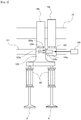
- Each cylinder 2 of the internal combustion engine 1 is provided with a first variable valve actuation system 100 for switching the operation mode of the intake valve 8 between the inactive mode in which the operation of opening/closing the intake valve 8 is disabled and the active mode in which the operation of opening/closing the intake valve 8 is enabled.
- Each cylinder 2 of the internal combustion engine 1 is further provided with a second variable valve actuation system 110 for switching the operation mode of the exhaust valve 9 between the inactive mode and the active mode.
- the structure of the first variable valve actuation system 100 and the second variable valve actuation system 110 will be described with reference to Figs. 2 and 3 .
- the first variable valve actuation system 100 and the second variable valve actuation system 110 have the same structure, and hence only the first variable valve actuation system 100 will be described in the following.
- the first variable valve actuation system 100 includes two cams 10a, 10b attached to the intake cam shaft 10, a rocker shaft 121 arranged parallel to the intake cam shaft 10, two rocker arms 122, 123 attached to the rocker shaft 121 in a slidable manner, a lock mechanism 124 for switching between the connection and separation of the two rocker arms 122, 123, and an oil control valve (OCV) 125 for switching between the application and relaxation of hydraulic oil pressure to the lock mechanism 124.
- OCV oil control valve
- One cam 10a (which will be referred to as the first cam 10a hereinafter) among the two cams 10a, 10b attached to the intake cam shaft 10 has a cam profile with a duration and lift (i.e. the height of the cam nose) larger than zero.
- the other cam 10b (which will be referred to as the second cam 10b hereinafter) among the two cams 10a, 10b has a cam profile with a duration and lift equal to zero. In other words, the second cam 10b has only the base circle.
- rocker arm 122 (which will be referred to as the first rocker arm 122 hereinafter) among the two rocker arms 122, 123 attached to the rocker shaft 121 is pressed against the first cam 10a by the effect of a coil spring or lash adjuster not shown in the drawings and rocked by the cam nose of the first cam 10a.
- the other rocker arm 123 (which will be referred to as the second rocker arm 123) among the two rocker arms 122, 123 has an end to which the base end of the intake valve 8 (i.e. the base end of the valve stem) abuts.
- the second rocker arm 123 is pressed against the second cam 10b by the effect of the valve spring 80 of the intake valve 8 and a coil spring or lash adjuster not shown in the drawings.
- the lock mechanism 124 includes a separation pin 124a, a lock pin 124b, and a separating spring 124c.
- the separation pin 124a is received in a first pin bore 123a provided in the second rocker arm 123 in a slidable manner.
- the first pin bore 123a is provided on the surface of the second rocker arm 123 that faces the first rocker arm 122.
- the axis of the first pin bore 123a is parallel to the axis of the rocker shaft 121.
- the separating spring 124c is set on the bottom of the first pin bore 123a to bias the separation pin 124a in the direction toward the first rocker arm 122.
- the lock pin 124b is received in a second pin bore 122a provided in the first rocker arm 122 in a slidable manner.
- the position of the second pin bore 122a in the first rocker arm 122 is designed in such a way that the second pin bore 122a is opposed to the first pin bore 123a when the first rocker arm 122 abuts to the base circle of the first cam 10a.
- the axis of the second pin bore 122a is parallel to the axis of the rocker shaft 121.
- the separating pin 124a, the lock pin 124b, the second pin bore 122a, and the first pin bore 123a are dimensioned in such a way as to satisfy the following two conditions.
- the first condition is that when the base end (right end in Fig. 2 ) of the lock pin 124b abuts to the bottom of the second pin bore 122a, the top end (left end in Fig. 2 ) of the lock pin 124b and the top end (right end in Fig. 2 ) of the separation pin 124a are located in a gap between the first rocker arm 122 and the second rocker arm 123, as shown in Fig. 2 .
- the second condition is that when the base end (left end in Fig.
- the OCV 125 selectively establishes a state in which the hydraulic oil pressure is applied to the operation space and a state in which the hydraulic oil pressure in the operation chamber is relaxed.
- the biasing force of the separating spring 124c is greater than the hydraulic oil pressure in the operation chamber, so that the separation pin 124a and the lock pin 124b are pushed in the direction from the second rocker arm 123 to the first rocker arm 122.
- the base end of the lock pin 124b abuts the bottom of the second pin bore 122a.
- the state shown in Fig. 2 is established, in which the top end of the separation pin 124a and the top end of the lock pin 124b are located in the gap between first rocker arm 122 and the second rocker arm 123.
- the first rocker arm 122 and the second rocker arm 123 are separated.
- the motion of the first rocker arm 122 is not transmitted to the second rocker arm 123.
- the motion of the second rocker arm 123 follows the cam profile of the second cam 10b.
- the second cam 10b has a cam profile that makes the duration and the lift equal to zero as described above. Therefore, when the first rocker arm 122 and the second rocker arm 123 are in the separated state, the second rocker arm 123 does not rock. In consequence, the operation of opening/closing the intake valve 8 is disabled (inactive mode).
- the hydraulic oil pressure in the operation chamber is greater than the biasing force of the separating spring 124c, so that the separation pin 124a and the lock pin 124b are pushed in the direction from the first rocker arm 122 to the second rocker arm 123.
- the base end of the separation pin 124a abuts the bottom of the first pin bore 123a.
- the above-described first variable valve actuation system 100 (and the second variable valve actuation system 110) constitutes the variable valve actuation system according to the present invention.
- the structure shown in Figs. 2 and 3 is an illustrative example of the variable valve actuation system according to the present invention, and the structure shown in Figs. 2 and 3 is not intended to limit the variable valve actuation system according to the present invention.
- an ECU 14 is provided for the internal combustion engine 1.
- the ECU 14 is an electronic control unit composed of a CPU, a ROM, a RAM, and a backup RAM etc.
- the ECU 14 is electrically connected with various sensors such as a crank position sensor 15, a water temperature sensor 16, and an accelerator position sensor 17.
- the crank position sensor 15 is a sensor that outputs an electrical signal representing the rotational position of the crankshaft 5.
- the water temperature senor 16 is a sensor that outputs an electrical signal representing the temperature of cooling water circulating in the internal combustion engine 1.
- the accelerator position sensor 17 is a sensor that outputs an electrical signal representing the amount of operation of the accelerator pedal (or the accelerator opening degree).
- the ECU 14 is also electrically connected with various components such as the fuel injection valve 12, the ignition plug 13, the first variable valve actuation system 100, and the second variable valve actuation system 110.
- the ECU 14 controls the aforementioned components on the basis of the output signals of the aforementioned sensors. For example, the ECU 14 determines the fuel injection quantity, fuel injection timing and the ignition timing on the basis of the engine speed calculated from the output signal of the crank position sensor 15 and the engine load calculated from the output signal of the accelerator position sensor 17 and controls the fuel injection valve 12 and the ignition plug 13 in accordance with the determined particulars.
- the ECU 14 performs the control of deactivating some of the cylinders 2 of the internal combustion engine 1 and changing the deactivated cylinders 2 (skip firing control) besides the aforementioned known controls to cause the internal combustion engine 1 to operate in the cylinder deactivation mode.
- skip firing control the deactivated cylinders 2
- the skip firing control is the control of deactivating some of the cylinders 2 in the operation range in which the engine load is lower than a specific load (which will be referred to as the cylinder deactivation operation range) by suspending the operation of the fuel injection valve 12 and the ignition plug 13 of some of the cylinders 2 of the internal combustion engine 1 and setting the mode of operation of the intake and exhaust valves 8, 9 of those cylinders 2 to the inactive mode.
- the number of cylinders deactivated in the skip firing control is varied according to the engine load. Specifically, the number of deactivated cylinders is larger when the engine load is low than when the engine load is high. Changing the deactivated cylinders by the skip firing control reduces variations in the conditions, such as the temperature, inside the cylinders.
- the tables in Fig. 4 show the active state and the deactivated state of the respective cylinders in an internal combustion engine having six cylinders.
- Table (a) in Fig. 4 shows a case where two cylinders are deactivated in one cycle
- table (b) shows a case where three cylinders are deactivated in one cycle.
- circles indicate the active state
- crosses indicate the deactivated state.
- each cylinder is deactivated once every three cycles, and the deactivated cylinders are changed in every cycle.
- the #1 cylinder and the #4 cylinder are firstly deactivated in the first cycle, then the #2 cylinder and the #5 cylinder are deactivated in the second cycle, and then the #3 cylinder and the #6 cylinder are deactivated in the third cycle.
- the #1 cylinder and the #4 cylinder are deactivated again. Performing such sequential deactivation repeatedly can uniformize the condition in the cylinders while deactivating two cylinders in every cycle.
- each cylinder is deactivated once in every two cycles, and the deactivated cylinders are changed in every cycle.
- the #1 cylinder, the #3 cylinder and the #5 cylinder are firstly deactivated in the first cycle, and then the #2 cylinder, the #4 cylinder, and the #6 cylinder are deactivated in the second cycle.
- the #1 cylinder, the #3 cylinder and the #5 cylinder are deactivated again. Performing such sequential deactivation repeatedly can uniformize the condition in the cylinders while deactivating three cylinders in every cycle.
- the skip firing control according to table (b) in Fig. 4 is performed when the engine load is lower than that in the case where the skip firing control is performed according to table (a) in Fig. 4 .
- the sequences shown in tables (a) and (b) in Fig. 4 are examples of the skip firing control.
- the cylinders to be deactivated in each cycle and the number of cylinders deactivated in each cycle may be changed appropriately taking account of the firing order of the cylinders, vibrations of the cylinders, and noises.
- the first variable valve actuation system 100 (the second variable valve actuation system 110) in a period in which the mode switching does not affect the operation of opening/closing the intake and exhaust valves 8, 9 during the period from the end of the intake stroke (the exhaust stroke) in the present cycle and the start of the intake stroke (the exhaust stroke) in the next cycle.
- the length of time from the beginning to the end of the aforementioned period in which the mode switching does not affect the operation of opening/closing the intake and exhaust valves 8, 9 changes depending on the engine speed. More specifically, the switchable time decreases with increasing engine speed. When the engine speed is somewhat high, the switchable time can be shorter than the time taken for the first variable valve actuation system 100 (the second variable valve actuation system 110) to carry out the mode switching (mode switching time).
- the skip firing control is performed when the switchable time is shorter than the mode switching time, increases in harmful exhaust emissions and/or misfire can occur in the next and subsequent cycles because of difficulty in completing the mode switching operation by the first variable valve actuation system 100 (the second variable valve actuation system 110) within the aforementioned switchable time.
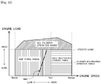
- the skip firing control is performed in the operation range in which the engine speed is equal to or lower than a first engine speed Ne1 (skip firing range) in the cylinder deactivation operation range in which the engine load is lower than the specific load, but the skip firing control is not performed in the operation range in which the engine speed is higher than the first engine speed Ne1 (fixed deactivated cylinder range) in the cylinder deactivation operation range.
- the first engine speed Ne1 mentioned above is an engine speed above which the switchable time is shorter than the mode switching time or such an engine speed minus a certain margin.
- Nemin is the minimum allowable engine speed of the internal combustion engine 1 (e.g. idle engine speed)
- Nemax is the maximum allowable engine speed of the internal combustion engine 1.
- the skip firing control is not performed in the operation range in which the switchable time is supposed to be shorter than the mode switching time (fixed deactivated cylinder range) in the cylinder deactivation operation range.
- a fixed deactivated cylinder control is performed instead of the skip firing control in the aforementioned fixed deactivated cylinder range.
- the fixed deactivated cylinder control is the process of controlling the fuel injection valve 12, the ignition plug 13, the first variable valve actuation system 100, and the second variable valve actuation system 110 in such a way as to deactivate specific cylinders among the plurality of cylinders 2 of the internal combustion engine 1.
- the fixed deactivated cylinder control it is not necessary for the fixed deactivated cylinder control to complete the mode switching operation by the first variable valve actuation system 100 (the second variable valve actuation system 110) within a limited time like the aforementioned switchable time.
- the fuel injection valve 12 and the ignition plug 13 of the specific cylinder are stopped operating, and the first variable valve actuation system 100 (the second variable valve actuation system 110) is controlled in such a way as to switch the mode of operation of the intake and exhaust valves 8, 9 from the active mode to the inactive mode.
- the combustion of fuel in the specific cylinder can be ceased, although there is a possibility that the mode switching operation by the first variable valve actuation system 100 (the second variable valve actuation system 110) may not be completed within the switchable time.
- the first variable valve actuation system 100 (the second variable valve actuation system 110) is firstly controlled in such a way as to switch the mode of operation of the intake and exhaust valves 8, 9 of the specific cylinder from the inactive mode to the active mode.
- the operation of the fuel injection valve 12 and the ignition plug 13 is restarted.
- cylinder deactivation can be performed in the internal combustion engine 1 while preventing increases in harmful exhaust emissions and misfire from being caused by the incompletion of the mode switching operation by the first variable valve actuation system 100 (the second variable valve actuation system 110) within the switchable time.
- Fig. 6 is a flow chart of a processing routine executed by the ECU 14 to set the first engine speed Ne1. This processing routine is stored in the ROM of the ECU 14 and executed repeatedly during the operation of the internal combustion engine 1.
- Fig. 7 is a graph showing relationship between the temperature Toil of the hydraulic oil in the first variable valve actuation system 100 (the second variable valve actuation system 110) and the first engine speed Ne1.
- step S101 the ECU 14 determines the temperature Toil of the hydraulic oil in the first variable valve actuation system 100 (the second variable valve actuation system 110).
- the temperature Toil of the hydraulic oil is calculated from the output signal of the water temperature sensor 16 (cooling water temperature). Relationship between the cooling water temperature and the hydraulic oil temperature Toil may be determined in advance by, for example, experiment or simulation.
- an oil temperature sensor may be provided in the channel of the hydraulic oil in the first variable valve actuation system 100 (the second variable valve actuation system 110), and the output signal of the oil temperature sensor may be used as the hydraulic oil temperature Toil.
- the ECU 14 embodies the detector according to the present invention in executing the processing of step S101.
- the ECU 14 determines whether or not the hydraulic oil temperature Toil determined in the processing of step S102 is equal to or higher than a lower limit temperature Tmp0.
- the lower limit temperature Tmp0 is a value of the hydraulic oil temperature below which it may be concluded that it is difficult to perform the skip firing control at any allowable engine speed of the internal combustion engine 1.
- the lower limit temperature Tmp0 e.g. -10°C
- Ne1min is a value of the hydraulic oil temperature Toil below which the switchable time can be shorter than the mode switching time even when the engine speed is at a specific lower limit Ne1min (idle engine speed).
- step S103 the ECU 14 sets the enable flag to ON.
- the enable flag is a flag that is set to ON when the hydraulic oil temperature Toil is in the temperature range in which the skip firing control may be performed (namely when the hydraulic oil temperature Toil is equal to or higher than the aforementioned lower limit temperature Tmp0) and set to off when the hydraulic oil temperature Toil is not in the temperature range in which the skip firing control may be performed (namely when the hydraulic oil temperature is lower than the aforementioned lower limit temperature Tmp0).
- the ECU 14 executes the processing of step S104 next.
- the ECU 14 determines whether or not the hydraulic oil temperature Toil determined in the processing of step S101 is lower than a warming-up completion temperature Tmp1.
- the warming-up completion temperature Tmp1 mentioned above is a value of the hydraulic oil temperature Toil at or above which the mode switching time is substantially stable at a certain time and below which the mode switching time is supposed to vary depending on the hydraulic oil temperature Toil.
- step S104 If an affirmative determination is made in step S104 (Toil ⁇ Tmp1), it may be presumed that the mode switching time varies depending on the hydraulic oil temperature Toil. Therefore, if an affirmative determination is made in step S104, then in step S105 the ECU 14 sets the first engine speed Ne1 using the hydraulic oil temperature Toil determined in step S101 as a parameter.
- the hydraulic oil temperature Toil is in the temperature range equal to or higher than the aforementioned lower limit temperature Tmp0 and lower than the aforementioned warming-up completion temperature Tmp1
- the mode switching time of the first variable valve actuation system 100 increases with decreasing hydraulic oil temperature Toil.
- step S102 If a negative determination is made in step S102 (Toil ⁇ Tmp0), it may be presumed that it is difficult to perform the skip firing control at any allowable engine speed of the internal combustion engine 1. Therefore, if a negative determination is made in step S102, then in step S106, the ECU 14 sets the enable flag to OFF.
- step S104 If a negative determination is made in step S104 (Toil ⁇ Tmp1), it may be presumed that warming-up of the first variable valve actuation system 100 (the second variable valve actuation system 110) has been completed and the mode switching time is substantially stable at a certain time, as described above. Therefore, if a negative determination is made in step S104, the ECU 14 executes the processing of step S107 next. In step S107, the ECU 14 fixes the first engine speed Ne1 at a specific upper limit value Nelmax.
- the specific upper limit value Ne1max mentioned above is a value of the engine speed equal to the engine speed at which the switchable time is equal to the mode switching time in the case where the hydraulic oil temperature Toil is higher than the warming-up completion temperature Tmpl, minus a certain margin.
- Fig. 8 is a flow chart of a processing routine executed by the ECU 14 when performing cylinder deactivation in the internal combustion engine 1. This processing routine is stored in the ROM of the ECU 14 and executed repeatedly during the operation of the internal combustion engine 1.
- step S201 the ECU 14 retrieves the engine speed Ne and the engine Load Q.
- the engine speed Ne is calculated from the output signal of the crank position sensor 15 by a separate routine and saved in the RAM or the like of the ECU 14.
- the engine load Q is calculated from the output signal of the accelerator position sensor 17 by a separate routine and saved in the RAM or the like of the ECU 14.
- step S202 the ECU 14 determines whether or not the engine load Q retrieved in step S201 is lower than a predetermined load Qpre.
- the predetermined load Qpre mentioned above is a value of the engine load Q at or below which the thermal efficiency is supposed to be higher in the case where cylinder deactivation is performed (namely, the internal combustion engine 1 operates with fewer cylinders) than in the case where the internal combustion engine 1 operates with all the cylinders.
- step S206 the ECU 14 causes all the cylinders of the internal combustion engine 1 to operate (all-cylinder operation). Specifically, the ECU 14 causes the fuel injection valve 12 and the ignition plug 13 to operate and controls the first variable valve actuation system 100 and the second variable valve actuation system 110 so as to bring the intake and exhaust valves 8, 9 into the active mode in all the cylinders of the internal combustion engine 1.
- step S203 the ECU 14 determines whether or not the enable flag is ON. As described above, the enable flag is set to ON when the hydraulic oil temperature Toil is in the temperature range in which the skip firing control may be performed and to OFF when the hydraulic oil temperature Toil is not in the temperature range in which the skip firing control may be performed. The enable flag has been set in the above-described processing routine shown in Fig. 6 .
- step S207 the ECU 14 executes the fixed deactivated cylinder control. Specifically, the ECU 14 suspends the operation of the fuel injection valve 12 and the ignition plug 13 and controls the first variable valve actuation system 100 and the second variable valve actuation system 110 so as to bring the intake and exhaust valves 8, 9 in specific cylinders of the internal combustion engine 1. The number of deactivated cylinders is larger when the engine load Q is low than when the engine load Q is high.
- step S204 the ECU 14 determines whether or not the engine speed Ne retrieved in step S201 is equal to or lower than the first engine speed Ne1.
- the first engine speed Ne1 is a value of the engine speed Ne above which the switchable time is supposed to be shorter than the mode switching time.
- the first engine speed Ne1 is set in the above-described processing routine shown in Fig. 7 .
- step S204 If an affirmative determination is made in step S204 (Ne ⁇ Ne1), it may be concluded that the hydraulic oil temperature Toil is in the temperature range in which the skip firing control may be performed and the engine speed Ne is in the engine speed range in which the skip firing control may be performed. In other words, if an affirmative determination is made in step S204, it may be concluded that the internal combustion engine 1 is operating in an operation range in which the switchable time is longer than the mode switching time. Therefore, if an affirmative determination is made in step S204, the ECU 14 executes the processing of step S205 next to perform the skip firing control. In performing the skip firing control, the ECU 14 determines the cylinders to be deactivated in each cycle and the number of deactivated cylinders on the basis of the engine load Q and the tables shown in Fig. 4 .
- step S204 determines whether a negative determination is made in step S204 (Ne > Ne1), it may be concluded that while the hydraulic oil temperature Toil is in the temperature range in which the skip firing control may be performed, the engine speed Ne is not in the engine speed range in which the skip firing control may be performed. In other words, if a negative determination is made in step S204, it may be concluded that the internal combustion engine is operating in an operation range in which the switchable time is shorter than the mode switching time. Therefore, if a negative determination is made in step S204, the ECU 14 executes the processing of step S207 to perform the fixed deactivated cylinder control.
- cylinder deactivation is performed in the internal combustion engine 1 by the skip firing control in the operation range (skip firing range) in which the switchable time is longer than the mode switching time, but the skip firing control is not performed in the operation range (fixed deactivated cylinder range) in which the switchable time is shorter than the mode switching time.
- the skip firing control is not performed in the operation range (fixed deactivated cylinder range) in which the switchable time is shorter than the mode switching time.
- cylinder deactivation is performed in the internal combustion engine 1 by the fixed deactivated cylinder control instead of the skip firing control. Therefore, the thermal efficiency of the internal combustion engine 1 can be enhanced while preventing increases in harmful exhaust emissions and misfire from occurring.
- the controller according to the present invention is embodied by the ECU 14 in executing the processing routines shown in Figs. 6 and 8 .
- a second embodiment of the present invention will be described next with reference to Figs. 9 to 11 .
- features in the second embodiment that are different from those in the first embodiment will be described, and like features will not be described.
- the difference between the second embodiment and the above-described first embodiment resides in that while the threshold of the engine speed at which the skip firing control is switched to the fixed deactivated cylinder control is set at the first engine speed, the threshold of the engine speed at which the fixed deactivated cylinder control is switched to the skip firing control is set at a second engine speed lower than the first engine speed.
- the degree of fluctuations of the engine speed Ne tend to be larger when cylinder deactivation is performed in the internal combustion engine 1 than when the all-cylinder operation is performed in the internal combustion engine 1. For this reason, even in cases where the operation condition of the internal combustion engine 1 is stable with the engine speed Ne close to the first engine speed Ne1, there is a possibility that the engine speed Ne may fluctuate above and below the first engine speed Ne1.
- the threshold of the engine speed at which the fixed deactivated cylinder control is switched to the skip firing control is set at the same value as the first engine speed Ne1 as the threshold at which the skip firing control is switched to the fixed deactivated cylinder control, there is a possibility that the engine speed Ne may become higher than the first engine speed Ne1 again soon after switching from the fixed deactivated cylinder control to the skip firing control and the engine speed Ne may become lower than the first engine speed Ne1 again soon after switching from the skip firing control to the fixed deactivated cylinder control.
- the threshold of the engine speed at which the fixed deactivated cylinder control is switched to the skip firing control is set at a second engine speed Ne2 lower than the first engine speed Ne1, in this embodiment.
- FIG. 9 is a flow chart of a processing routine executed by the ECU 14 to set the first engine speed Ne1 and the second engine speed Ne2.
- Fig. 10 is a graph showing relationship between the first engine speed Ne1 and the second engine speed Ne2.
- the processing same as that in the above-described processing routine shown in Fig. 6 are denoted by the same reference signs.
- the method of setting the first engine speed Ne1 is the same as that shown in Fig. 6 .
- the subtraction value Cq mentioned above is a positive value larger than zero, and the lower the engine load Q is, the larger the subtraction value Cq is set.
- the second engine speed Ne2 set as above is an engine speed that is lower than the first engine speed Ne1 and decreases with decreasing engine load Q as indicated by the dash-dot line in Fig. 10 .
- the reason why the second engine speed Ne2 is varied depending on the engine load Q is that the higher the engine load Q is, the larger the number of cylinders deactivated in the skip firing control or the fixed deactivated cylinder control is, and larger the degree of fluctuations of the engine speed Ne is. Setting the second engine speed Ne2 in the above-described manner can prevent switching between the skip firing control and the fixed deactivated cylinder control from occurring alternately at short intervals in the operation state in which the engine speed Ne is close to the first engine speed Ne1. Thus, hunting in control can be prevented from occurring.
- Fig. 11 is a flow chart of a processing routine executed by the ECU 14 when performing cylinder deactivation in the internal combustion engine 1. This processing routine is stored in the ROM of the ECU 14 and executed repeatedly during the operation of the internal combustion engine 1. In Fig. 11 , the processing steps the same as those in Fig. 8 are denoted by the same reference signs.
- step S301 it is determined whether or not the fixed deactivated cylinder control is being performed. If the control mode has been switched from the skip firing control to the fixed deactivated cylinder control and the engine speed Ne is changing from engine speeds higher than the first engine speed Ne1 to engine speeds lower than the first engine speed Ne1 at that time, the fixed deactivated cylinder control is being performed. Then, an affirmative determination is made in step S301. If an affirmative determination is made in step S301, then in step S302 the ECU 14 determines whether or not the engine speed Ne retrieved in step S201 is equal to or lower than the second engine speed Ne2.
- step S302 If an affirmative determination is made in step S302, then in step S205 the ECU 14 switches the control from the fixed deactivated cylinder control to the skip firing control. On the other hand, if a negative determination is made in step S302 (Ne > Ne2), then in step S207 the ECU 14 continues the fixed deactivated cylinder control. If a negative determination is made in step S301, the ECU 14 skips the processing of step S302 and executes the processing of step S205.
- the processing shown in Fig. 11 can prevent switching between the skip firing control and the fixed deactivated cylinder control from occurring at short intervals in the operation state in which the engine speed Ne is close to the first engine speed Ne1. Thus, hunting in control can be prevented from occurring.
- a third embodiment of the present invention will be described with reference to Figs. 12 and 13 .
- features in the third embodiment that are different from those in the above-described first embodiment will be described, and like features will not be described.
- the difference between the third embodiment and the above-described first embodiment resides in that the first engine speed is corrected taking account of changes in the mode switching time resulting from deterioration of the hydraulic oil over time.
- the response speed of the first variable valve actuation system 100 and the second variable valve actuation system 110 lowers. This is because the rate of change of the hydraulic oil pressure during mode switching between the inactive mode and the active mode by the first variable valve actuation system 100 (the second variable valve actuation system 110) decreases with progress of deterioration of the hydraulic oil over time. More particularly, the rate of change of the hydraulic oil pressure immediately after the switching between the application and the relaxation of the hydraulic oil pressure to the operation chamber of the first variable valve actuation system 100 (the second variable valve actuation system 110) decreases with progress of deterioration of the hydraulic oil over time.
- the response speed of the first variable valve actuation system 100 decreases due to deterioration of the hydraulic oil over time, there is a possibility that the mode switching time may become longer than a presumed time. For this reason, as the deterioration of the hydraulic oil progresses to some degree over time circumstances in which the switchable time becomes shorter than mode switching time can arise at engine speeds lower than the presumed first engine speed Ne1.
- the rate of change of the hydraulic oil pressure is determined when the mode switching by the first variable valve actuation system 100 (the second variable valve actuation system 110) is being performed in the operation range in which the engine speed Ne is equal to or lower than a predetermined threshold that is lower than the first engine speed Ne1, and the first engine speed Ne1 is corrected according to the rate of change of the hydraulic oil pressure.
- the rate of change of the hydraulic oil pressure it is necessary to measure the hydraulic oil pressure in the first variable valve actuation system 100 (the second variable valve actuation system 110).
- an oil pressure sensor 126 for measuring the hydraulic oil pressure is provided in the hydraulic pressure channel between the OCV 125 and the operation chamber as shown in Fig. 12 , and the output signal of the oil pressure sensor 126 is input to the ECU 14.
- the determination of the rate of change of the hydraulic oil pressure and the correction of the first engine speed Ne1 based on the rate of change be performed when the engine speed Ne is sufficiently lower than the first engine speed Ne1 before correction. This is because if the aforementioned determination and correction are performed when the engine speed is close to the first engine speed Ne1 before correction, there is a possibility that circumstances in which the switchable time becomes shorter than mode switching time may arise before the correction of the first engine speed Ne1 is performed.
- the rate of change of the hydraulic oil pressure is determined when the engine speed Ne is equal to or lower than a specific threshold that is sufficiently lower than the first engine speed Ne1 before correction, and if the determined rate of change of the hydraulic oil pressure is lower than a specific criterion value, the first engine speed Ne1 is corrected to a lower engine speed.
- the specific threshold mentioned above is, for example, an engine speed that is so low that the switchable time will not become shorter than the mode switching time even if the hydraulic oil is deteriorated.
- the specific criterion value mentioned above is a value of the rate of change of the hydraulic oil pressure below which the mode switching time is supposed to become longer than a presumed time.
- Fig. 13 is a flow chart of a processing routine executed by the ECU 14 to correct the first engine speed Ne1. This processing routine is stored in the ROM of the ECU 14 and executed repeatedly during the operation of the internal combustion engine 1.
- step S401 the ECU 14 retrieves the hydraulic oil temperature Toil and the engine speed Ne. Then, in step S402, the ECU 14 determines whether or not the hydraulic oil temperature Toil retrieved in step S401 is equal to or higher than the aforementioned lower limit temperature Tmp0. If a negative determination is made in step S402 (Toil ⁇ Tmp0), the enable flag is set to OFF as described above description with Figs. 6 and 8 , and the skip firing control is not performed. Then, the rate of change Vp of the hydraulic pressure during the mode switching by the first variable valve actuation system 100 (the second variable valve actuation system 110) cannot be determined.
- step S402 the ECU 14 terminates the execution of this processing routine without performing determination of the rate of change Vp and correction of the first engine speed Ne1.
- step S403 the ECU 14 executes the processing of step S403 next.
- step S403 the ECU 14 determines whether or not the engine speed Ne read in step S401 is equal to or lower than the specific threshold Nethre.
- the specific threshold Nethre is a value of the engine speed that is sufficiently lower than the first engine speed Ne1 before correction and so low that the switchable time does not become shorter than the mode switching time even if the hydraulic oil is deteriorated. If a negative determination is made in step S403 (Ne > Nethre), the ECU 14 terminates the execution of this processing routine. On the other hand, if an affirmative determination is made in step S403 (Ne ⁇ Nethre), the ECU 14 executes the processing of step S404 next.
- step S404 the ECU 14 calculates the rate of change Vp of the hydraulic pressure during the mode switching by the first variable valve actuation system 100 (the second variable valve actuation system 110). For example, the ECU 14 may calculate the change in the hydraulic pressure during a specific time from the measurement value of the hydraulic pressure sensor 126 at the time when the mode switching control of the first variable valve actuation system 100 (the second variable valve actuation system 110) is started and the measurement value of the hydraulic pressure sensor 126 after the lapse of the aforementioned specific time from that time and calculate the rate of change Vp from the change in the hydraulic pressure thus calculated.
- the ECU 14 may calculate the length of time from the time when the mode switching control of the first variable valve actuation system 100 (the second variable valve actuation system 110) is started to the time when the measurement value of the hydraulic oil sensor 126 reaches a specific value and calculate the rate of change Vp from the length of time thus calculated.
- the ECU 14 embodies the acquirer according to the present invention in executing the processing of step S404.
- the ECU 14 determines whether or not the rate of change Vp is lower than a specific criterion value Vst in step S405.
- the specific criterion value Vst is a value of the rate of change Vp of the hydraulic oil pressure below which the mode switching time is supposed to become longer than a presumed time.
- the mode switching time is substantially constant when the hydraulic oil temperature Toil is equal to or higher than the warming-up completion temperature Tmpl, the mode switching time varies depending on the hydraulic oil temperature Toil when the hydraulic oil temperature Toil is in the temperature range equal to or higher than the lower limit temperature Tmp0 and lower than the warming-up completion temperature Tmp1.
- the specific criterion value Vst used in the processing of step S405 may be set taking account of this tendency. Specifically, if the hydraulic oil temperature Toil retrieved in step S401 is equal to or higher than warming-up completion temperature Tmp1, the specific criterion value Vst may be set to a specific fixed value. If the hydraulic oil temperature Toil is in the temperature range equal to or higher than the lower limit temperature Tmp0 and lower than the warming-up completion temperature Tmp1, the specific criterion value Vst may be set as a variable value that is smaller than the aforementioned specific fixed value and decreased with decreasing hydraulic oil temperature Toil.
- step S405 If a negative determination is made in step S405, it may be concluded that the deterioration of the hydraulic oil has not progressed yet to a degree that makes the mode switching time longer than a presumed length of time. Then, the ECU 14 terminates the execution of this processing routine without performing correction of the first engine speed Ne1. On the other hand, if an affirmative determination is made in step S405, it may be concluded that the deterioration of the hydraulic oil has progressed to a degree that makes the mode switching time longer than a presumed length of time. Then, it is necessary to correct the first engine speed Ne1. Hence, if an affirmative determination is made in step S405, the ECU 14 executes the processing of step S406 next.
- step S406 the ECU 14 corrects the first engine speed Ne1 by subtracting a correction value ⁇ Ne from the presently set first engine speed Nelold.
- the skip firing control is prevented from being performed in the operation range in which the switchable time is shorter than the mode switching time with improved reliability even if the hydraulic oil is deteriorated.
- the second engine speed Ne2 may also be corrected in the same manner as the correction of the first engine speed Ne1. Specifically, in cases where the first engine sped Ne1 is corrected, the second engine speed Ne2 may be corrected by subtracting the correction value ⁇ Ne from the presently set second engine speed Ne2old. By correcting the second engine speed Ne2, the skip firing control and the fixed deactivated cylinder control is prevented from occurring alternately at short intervals even if the hydraulic oil is deteriorated over time.
- the engine load is used as a parameter in switching cylinder deactivation and all-cylinder operation and changing the number of deactivated cylinders in cylinder deactivation
- the engine load factor i.e. the ratio of the actual intake air quantity to the intake air quantity at full load
- variable valve actuation system of the internal combustion engine to which the present invention is applied is a hydraulic variable valve actuation system that switches the mode of operation of the intake and exhaust valves between the inactive mode and the active mode using the pressure of hydraulic oil
- a solenoid variable valve actuation system that switches the mode of operation of the intake and exhaust valves between the inactive mode and the active mode using a solenoid may be employed alternatively.
- the present invention is applied to an internal combustion engine having a solenoid variable valve actuation system, it is not necessary to change the first engine speed Ne1 or the second engine speed Ne2 depending on the hydraulic oil temperature.
Landscapes
- Engineering & Computer Science (AREA)
- Chemical & Material Sciences (AREA)
- Combustion & Propulsion (AREA)
- Mechanical Engineering (AREA)
- General Engineering & Computer Science (AREA)
- Output Control And Ontrol Of Special Type Engine (AREA)
- Electrical Control Of Air Or Fuel Supplied To Internal-Combustion Engine (AREA)
- Combined Controls Of Internal Combustion Engines (AREA)
Abstract
Description
- The present invention relates to a control apparatus for an internal combustion engine capable of performing cylinder deactivation, which is the operation of deactivating some cylinders among a plurality of cylinders.
- It is known to improve the thermal efficiency of internal combustion engines equipped with a plurality of cylinders by performing the operation of deactivating some of the cylinders when the engine load is relatively low (cylinder deactivation). When cylinder deactivation is performed in an internal combustion engine, combustion in the cylinders to be deactivated is stopped, and the mode of operation of the intake and exhaust valves of the cylinders to be deactivated is switched from an active mode (in which the operation of opening/closing the intake and exhaust valves is enabled) to an inactive mode (in which the operation of opening/closing the intake and exhaust valves is disabled) by a variable valve actuation system to thereby reduce the mechanical losses and the intake and exhaust losses resulting from the operation of opening/closing the intake and exhaust valves.
- If the deactivated cylinders in an internal combustion engine that performs the above-described cylinder deactivation are fixed to specific cylinders, the difference in the condition in the specific cylinders in the deactivated state and the other cylinders in the active state tends to be relatively large. Then, when the specific cylinders shift from inactive to active, there can arise a difference between the combustion state in the specific cylinders and the combustion state of the other cylinders. This can lead to increases in harmful exhaust emissions. To address this problem, there has been developed the control method of changing the deactivated cylinders when performing cylinder deactivation in an internal combustion engine (see, for example, Patent Literature 1). This control will be referred to as the "skip firing control" hereinafter.
- Patent Literature 1: Japanese Patent Application Laid-Open No.
2014-532145 - When changing the deactivated cylinders, it is necessary for the aforementioned skip firing control to activate in the next cycle the cylinders that are deactivated in the present cycle and to deactivate in the next cycle the cylinders that are active in the present cycle. In doing so, it is necessary to carry out the mode switching by the variable valve actuation system in a period in which the mode switching does not affect the operation of opening/closing the intake and exhaust valves during the period from the end of the intake stroke (or the exhaust stroke) in the present cycle and the start of the intake stroke (or the exhaust stroke) in the next cycle.
- The length of time from the beginning to the end of the aforementioned period in which the mode switching does not affect the operation of opening/closing the intake and exhaust valves decreases with increasing engine speed. This length of time will be hereinafter referred to as the "switchable time". When the engine speed is somewhat high, the aforementioned switchable time can be shorter than the time taken for the variable valve actuation system to carry out the mode switching operation (which will be hereinafter referred to as the "mode switching time"). If the skip firing control is performed in the operation range in which the switchable time is shorter than the mode switching time, increases in harmful exhaust emissions and/or misfire can occur in the next and subsequent cycles because of difficulty in completing the mode switching operation by the variable valve actuation system within the aforementioned switchable time.
- The present invention has been made in view of the above-described circumstances, and an object of the present invention is to prevent increases in harmful exhaust emissions and misfire from being caused by skip firing control in internal combustion engines capable of performing cylinder deactivation.
- To solve the above problem, according to the present invention that pertains to an internal combustion engine fitted with cylinder deactivation, the skip firing control is performed in the operation range in which the switchable time is equal to or longer than the mode switching time and not performed in the operation range in which the switchable time is shorter than the mode switching time.
- More specifically, according to the present invention there is provided a control apparatus applied to an internal combustion engine equipped with a plurality of cylinders, a variable valve actuation system capable of switching the operation mode of intake and exhaust valves of each of the cylinders between an inactive mode in which the operation of opening/closing the intake and exhaust valves of the cylinder is disabled and an active mode in which the operation of opening/closing the intake and exhaust valves of the cylinder is enabled on a cylinder-by-cylinder basis, and a fuel injection valve that supplies fuel into each of the cylinders of the internal combustion engine. The control apparatus includes a controller capable of performing skip firing control, which is the control of deactivating some of the cylinders by causing said variable valve actuation system to set the operation mode of the intake and exhaust valves of the some of the cylinders in said internal combustion engine to the inactive mode and causing the fuel injection valve of the some of the cylinders to suspend supply of fuel and changing the deactivated cylinders. Said controller performs said skip firing control when the engine speed is equal to or lower than a first engine speed and does not perform said skip firing control when the engine speed is higher than said first engine speed.
- The first engine speed mentioned above is an engine speed above which the aforementioned switchable time is shorter than the mode switching time or such an engine speed minus a certain margin.
- The above-described control apparatus for an internal combustion engine performs the skip firing control when the engine speed is equal to or lower than the first engine speed. When the engine speed is equal to or lower than the first engine speed, the aforementioned switchable time is equal to or longer than the mode switching time, and it is possible to complete the mode switching operation by the variable valve actuation system within the switchable time. Therefore, if the skip firing control is performed when the engine speed is equal to or lower than the first engine speed, the deactivated cylinders can be changed without causing increases in harmful exhaust emissions or misfire. Moreover, the above-described control apparatus for an internal combustion engine does not perform the skip firing control when the engine speed is higher than the first engine speed. When the engine speed is higher than the first engine speed, the aforementioned switchable time is shorter than the mode switching time, and therefore it is difficult to complete the mode switching operation by the variable valve actuation system within the switchable time. Therefore, if the skip firing control is not performed when the engine speed is higher than the first engine speed, increases in harmful exhaust emissions and misfire are prevented from being caused by incompletion of the mode switching operation by the variable valve actuation system within the aforementioned switchable time.
- When the engine speed is higher than the first engine speed, the control apparatus for an internal combustion engine according to the present invention may cause all the cylinders to operate or alternatively continue cylinder deactivation with fixed deactivated cylinders. Thus, when the engine speed is higher than the first engine speed, the controller according to the present invention may perform fixed deactivated cylinder control to control said variable valve actuation system and said fuel injection valve in such a way as to deactivate specific cylinders among the plurality of cylinders. It is not necessary for the fixed deactivated cylinder control to complete the mode switching operation by the variable valve actuation system within the aforementioned switchable time. Therefore, cylinder deactivation can be performed in the internal combustion engine in operation ranges in which the aforementioned switchable time is shorter than the mode switching time while preventing increases in harmful exhaust emissions and misfire. Therefore, the thermal efficiency of the internal combustion engine can be enhanced.
- In the case where the control apparatus is adapted to switch the control mode from the skip firing control to the fixed deactivated cylinder control at the time when the engine speed becomes higher than the first engine speed, the control apparatus may be adapted to perform the fixed deactivated cylinder control and not to perform the skip firing control until the engine speed decreases to or below a second engine speed lower than said first engine speed after the engine speed has become higher than the first engine speed (namely after the switching from the skip firing control to the fixed deactivated cylinder control). In other words, after the engine speed has become higher than the first engine speed, switching from the fixed deactivated cylinder control to the skip firing control may be disabled until the engine speed decreases to or below the second engine speed. While cylinder deactivation is being performed in the internal combustion engine, the degree of fluctuations of the engine speed tends to be larger than when all the cylinders of the internal combustion engine are operating. For this reason, even in cases where the operation condition of the internal combustion engine is stable with the engine speed close to the first engine speed, there is a possibility that the engine speed may fluctuate about the first engine speed. In such cases, if the threshold of the engine speed at which the fixed deactivated cylinder control is switched to the skip firing control is set at the same value as the first engine speed as the threshold at which the skip firing control is switched to the fixed deactivated cylinder control, there is a possibility that after switching from the skip firing control to the fixed deactivated cylinder control, switching from the fixed deactivated cylinder control to the skip firing control and switching from the skip firing control to the fixed deactivated cylinder control may occur alternately in short intervals, resulting in hunting in control. To avoid this, the threshold of the engine speed at which the fixed deactivated cylinder control is switched to the skip firing control may be set at a second engine speed lower than the first engine speed as the threshold at which the skip firing control is switched to the fixed deactivated cylinder control. Thus, the above-described hunting in control can be prevented from occurring.
- To enhance the thermal efficiency of the internal combustion engine as much as possible, it is advantageous to make the number of deactivated cylinders larger when the engine load is low than when the engine load is high when performing the skip firing control or the fixed deactivated cylinder control. In the case where the number of deactivated cylinders is changed depending on the engine load, the degree of fluctuations of the engine speed tends to be larger when the engine load is low than when the engine load is high. Therefore, in the case where the control apparatus is adapted to change the number of deactivated cylinders depending on the engine load, the second engine speed may be set lower when the engine load is low than when the engine load is high. Setting the second engine speed in this way can prevent the above-described hunting in control from occurring even in the case where the number of deactivated cylinders is changed depending on the engine load.
- The variable valve actuation system in the internal combustion engine to which the present invention is applied may be a solenoid variable valve actuation system or a hydraulic variable valve actuation system. Since the mode switching operation by the variable valve actuation system is performed frequently in the skip firing control, the magnitude of operation noise of the variable valve actuation system tends to be high. In particular, the magnitude of the operation noise of solenoid variable valve actuation systems tends to be higher than that of the hydraulic variable valve actuation systems. Therefore, a hydraulic variable valve actuation system may be employed as the variable valve actuation system of internal combustion engines in which the skip firing control is performed. However, the response speed of hydraulic variable valve actuation systems is lower than that of solenoid variable valve actuation systems in some cases, and lower response speeds can lead to longer mode switching times. Even in the case of internal combustion engines equipped with a hydraulic variable valve actuation system, if the skip firing control is performed when the engine speed is equal to or lower than the first engine speed and not performed when the engine speed is higher than the first engine speed, increases in harmful exhaust emissions and misfire are prevented from being caused by performing the skip firing control.
- In the case where the internal combustion engine to which the present invention is applied is equipped with a hydraulic variable valve actuation system, the control apparatus may further includes a detector that measures the hydraulic oil temperature, namely the temperature of the hydraulic oil in the variable valve actuation system. When the hydraulic oil temperature measured by said detector is lower than a warming-up completion temperature, the controller may set said first engine speed lower when the hydraulic oil temperature is low than when the hydraulic oil temperature is high. The response speed of the hydraulic variable valve actuation system varies depending on the hydraulic oil temperature. In particular, when the hydraulic oil temperature is lower than the warming-up completion temperature, the response speed of the hydraulic variable valve actuation system is apt to vary depending on the hydraulic oil temperature. Specifically, when the hydraulic oil temperature is lower than the warming-up completion temperature, the response speed of the hydraulic variable valve actuation system tends to be lower, and the mode switching time tends to be longer according, when the hydraulic oil temperature is low than when it is high. In view of this, when the hydraulic oil temperature is lower than the warming-up completion temperature, the first engine speed may be set lower when the hydraulic oil temperature is low than when it is high. This can prevent the skip firing control from being performed in the operation range in which the switchable time is shorter than the mode switching time with improved reliability.
- In the case where the internal combustion engine to which the present invention is applied is equipped with a hydraulic variable valve actuation system, if the hydraulic oil is deteriorated over time, the response speed of the variable valve actuation system may decrease accordingly. Then, the mode switching time of the variable valve actuation system may become longer than a presumed time. To avoid this, the control apparatus according to the present invention may further include an acquirer that acquires the rate of change of the pressure of hydraulic oil when switching between the inactive mode and the active mode is being performed by said variable valve actuation system. If the rate of change acquired by said acquirer is lower than a specific criterion value when the engine speed is lower than a specific threshold lower than said first engine speed, said controller may correct said first engine speed to a lower engine speed. The specific threshold mentioned above is an engine speed that is sufficiently lower than the first engine speed before correction and at which it is supposed that the switchable time will not become shorter than the mode switching time even if the hydraulic oil is deteriorated over time. The specific criterion value mentioned above is a value of the rate of change of the hydraulic oil pressure below which the mode switching time is supposed to become longer than a presumed time. The above feature can prevent, with improved reliability, the skip firing control from being performed in the operation range in which the switchable time is shorter than the mode switching time, even if the hydraulic oil is deteriorated over time. In the above-described case, the acquisition of the rate of change of the pressure of the hydraulic oil and the correction of the first engine speed are performed when the engine speed is sufficiently lower than the first engine speed. This is because if the acquisition and correction are performed when the engine speed is close to the first engine speed, there is a possibility that the switchable time may become shorter than the mode switching time before the first engine speed is corrected, leading to increases in harmful exhaust emissions and/or misfire.
- The present invention can prevent increases in harmful exhaust emissions and misfire from being caused by skip firing control in internal combustion engines capable of performing cylinder deactivation.
-
-
Fig. 1 is a diagram showing the general configuration of an internal combustion engine to which the present invention is applied. -
Fig. 2 is a first diagram showing the general configuration of a first variable valve actuation system. -
Fig. 3 is a second diagram showing the general configuration of the first variable valve actuation system. -
Fig. 4 includes table (a) showing how the skip firing control is performed in a case where two cylinders are deactivated in one cycle and table (b) showing how the skip firing control is performed in a case where three cylinders are deactivated in one cycle. -
Fig. 5 is a diagram showing an operation range (skip firing range) in which the skip firing control is performed. -
Fig. 6 is a flow chart of a processing routine executed by an ECU to set a first engine speed in a first embodiment. -
Fig. 7 is a graph showing relationship between the hydraulic oil temperature Toil and a first engine speed Ne1. -
Fig. 8 is a flow chart of a processing routine executed by the ECU when performing cylinder deactivation in the internal combustion engine in the first embodiment. -
Fig. 9 is a flow chart of a processing routine executed by the ECU to set the first engine speed and a second engine speed in a second embodiment. -
Fig. 10 is a graph showing relationship between the first engine speed Ne1 and the second engine speed Ne2. -
Fig. 11 is a flow chart of a processing routine executed by the ECU when performing cylinder deactivation in the internal combustion engine in the second embodiment. -
Fig. 12 is a diagram showing the general configuration of a first variablevalve actuation system 100 in a third embodiment. -
Fig. 13 is a flow chart of a processing routine executed by the ECU to correct the first engine speed in the third embodiment. - In the following, specific embodiments of the present invention will be described with reference to the drawings. The dimensions, materials, shapes, relative arrangements, and other features of the components that will be described in connection with the embodiments are not intended to limit the technical scope of the present invention only to them, unless otherwise stated.
- A first embodiment of the present will be described with reference to
Figs. 1 to 8 .Fig. 1 is a diagram showing the general configuration of an internal combustion engine to which the present invention is applied. Theinternal combustion engine 1 shown inFig. 1 is a four-stroke spark-ignition internal combustion engine having a plurality of cylinders 2 (e.g. gasoline engine).Fig. 1 shows only one of the plurality of cylinders. The engines to which the present invention is to be applied are not limited to spark-ignition internal combustion engines like that shown inFig. 1 , but the present invention may also be applied to four-stroke compression-ignition internal combustion engines (e.g. diesel engines). - A
piston 3 is provided inside thecylinder 2 of theinternal combustion engine 1 in a slidable manner. Thepiston 3 is connected with acrankshaft 5 by a connectingrod 4. The space inside the cylinder 2 (which constitutes a combustion chamber) is in communication with anintake port 6 and anexhaust port 7. The end of theintake port 6 that open to thecylinder 2 is closed and opened by anintake valve 8. The end of theexhaust port 7 that opens to thecylinder 2 is closed and opened by anexhaust valve 9. Theintake valve 8 and theexhaust valve 9 are driven by anintake cam shaft 10 and anexhaust cam shaft 11 respectively for the opening/closing operation. - The
intake port 6 is in communication with anintake passage 60. Theintake passage 60 is provided with afuel injection valve 12 that injects fuel toward theintake port 6. Theintake passage 60 is a passage through which fresh air is delivered to theintake port 6. The intake air delivered to theintake port 6 is sucked into thecylinder 2 when theintake valve 8 opens. Moreover, fuel injected by thefuel injection valve 12 into theintake port 6 is also sucked into thecylinder 2 with the intake air. - The fuel and intake air (i.e. air-fuel mixture) taken into the
cylinder 2 is ignited by anignition plug 13 attached to eachcylinder 2 to burn. The gas burned in the cylinder 2 (burned gas) is discharged to theexhaust port 7 when theexhaust valve 9 opens. Theexhaust port 7 is in communication with anexhaust passage 70, and the aforementioned burned gas is emitted to the atmosphere through theexhaust port 7 and theexhaust passage 70. - Each
cylinder 2 of theinternal combustion engine 1 is provided with a first variablevalve actuation system 100 for switching the operation mode of theintake valve 8 between the inactive mode in which the operation of opening/closing theintake valve 8 is disabled and the active mode in which the operation of opening/closing theintake valve 8 is enabled. Eachcylinder 2 of theinternal combustion engine 1 is further provided with a second variablevalve actuation system 110 for switching the operation mode of theexhaust valve 9 between the inactive mode and the active mode. In the following, the structure of the first variablevalve actuation system 100 and the second variablevalve actuation system 110 will be described with reference toFigs. 2 and3 . The first variablevalve actuation system 100 and the second variablevalve actuation system 110 have the same structure, and hence only the first variablevalve actuation system 100 will be described in the following. - The first variable
valve actuation system 100 includes twocams intake cam shaft 10, arocker shaft 121 arranged parallel to theintake cam shaft 10, tworocker arms rocker shaft 121 in a slidable manner, a lock mechanism 124 for switching between the connection and separation of the tworocker arms - One
cam 10a (which will be referred to as thefirst cam 10a hereinafter) among the twocams intake cam shaft 10 has a cam profile with a duration and lift (i.e. the height of the cam nose) larger than zero. Theother cam 10b (which will be referred to as thesecond cam 10b hereinafter) among the twocams second cam 10b has only the base circle. - One rocker arm 122 (which will be referred to as the
first rocker arm 122 hereinafter) among the tworocker arms rocker shaft 121 is pressed against thefirst cam 10a by the effect of a coil spring or lash adjuster not shown in the drawings and rocked by the cam nose of thefirst cam 10a. The other rocker arm 123 (which will be referred to as the second rocker arm 123) among the tworocker arms second rocker arm 123 is pressed against thesecond cam 10b by the effect of thevalve spring 80 of theintake valve 8 and a coil spring or lash adjuster not shown in the drawings. - The lock mechanism 124 includes a
separation pin 124a, alock pin 124b, and aseparating spring 124c. Theseparation pin 124a is received in afirst pin bore 123a provided in thesecond rocker arm 123 in a slidable manner. Thefirst pin bore 123a is provided on the surface of thesecond rocker arm 123 that faces thefirst rocker arm 122. The axis of thefirst pin bore 123a is parallel to the axis of therocker shaft 121. The separatingspring 124c is set on the bottom of thefirst pin bore 123a to bias theseparation pin 124a in the direction toward thefirst rocker arm 122. Thelock pin 124b is received in asecond pin bore 122a provided in thefirst rocker arm 122 in a slidable manner. The position of thesecond pin bore 122a in thefirst rocker arm 122 is designed in such a way that thesecond pin bore 122a is opposed to thefirst pin bore 123a when thefirst rocker arm 122 abuts to the base circle of thefirst cam 10a. The axis of thesecond pin bore 122a is parallel to the axis of therocker shaft 121. - The separating
pin 124a, thelock pin 124b, thesecond pin bore 122a, and thefirst pin bore 123a are dimensioned in such a way as to satisfy the following two conditions. The first condition is that when the base end (right end inFig. 2 ) of thelock pin 124b abuts to the bottom of thesecond pin bore 122a, the top end (left end inFig. 2 ) of thelock pin 124b and the top end (right end inFig. 2 ) of theseparation pin 124a are located in a gap between thefirst rocker arm 122 and thesecond rocker arm 123, as shown inFig. 2 . The second condition is that when the base end (left end inFig. 2 ) of theseparation pin 124a abuts the bottom of thefirst pin bore 123a, the top end of thelock pin 124b and the top end of theseparation pin 124a are located in thefirst pin bore 123a and the base end of thelock pin 124b is located in thesecond pin bore 122a, as shown inFig. 3 . - There is a space in the
second pin bore 122a between the base end of thelock pin 124b and the bottom of thesecond pin bore 122a. This space will be hereinafter referred to as the operation chamber. TheOCV 125 selectively establishes a state in which the hydraulic oil pressure is applied to the operation space and a state in which the hydraulic oil pressure in the operation chamber is relaxed. - In the first variable
valve actuation system 100 structured as above, when theOCV 125 relaxes the hydraulic oil pressure in the operation chamber, the biasing force of the separatingspring 124c is greater than the hydraulic oil pressure in the operation chamber, so that theseparation pin 124a and thelock pin 124b are pushed in the direction from thesecond rocker arm 123 to thefirst rocker arm 122. In consequence, the base end of thelock pin 124b abuts the bottom of thesecond pin bore 122a. In other words, the state shown inFig. 2 is established, in which the top end of theseparation pin 124a and the top end of thelock pin 124b are located in the gap betweenfirst rocker arm 122 and thesecond rocker arm 123. In this state, thefirst rocker arm 122 and thesecond rocker arm 123 are separated. Thus, when thefirst rocker arm 122 is rocked by the cam nose of thefirst cam 10a, the motion of thefirst rocker arm 122 is not transmitted to thesecond rocker arm 123. In consequence, the motion of thesecond rocker arm 123 follows the cam profile of thesecond cam 10b. In this embodiment, thesecond cam 10b has a cam profile that makes the duration and the lift equal to zero as described above. Therefore, when thefirst rocker arm 122 and thesecond rocker arm 123 are in the separated state, thesecond rocker arm 123 does not rock. In consequence, the operation of opening/closing theintake valve 8 is disabled (inactive mode). - On the other hand, when the
OCV 125 is applying the hydraulic oil pressure to the operation chamber in the first variablevalve actuation system 100 structured as above, the hydraulic oil pressure in the operation chamber is greater than the biasing force of the separatingspring 124c, so that theseparation pin 124a and thelock pin 124b are pushed in the direction from thefirst rocker arm 122 to thesecond rocker arm 123. In consequence, the base end of theseparation pin 124a abuts the bottom of thefirst pin bore 123a. In other words, the state shown inFig. 3 is established, in which the top end of thelock pin 124b and the top end of theseparation pin 124a are located in thefirst pin bore 123a and the base end of thelock pin 124b is located in thesecond pin bore 122a. In this state, thefirst rocker arm 122 and thesecond rocker arm 123 are linked by thelock pin 124b. Thus, when thefirst rocker arm 122 is rocked by the cam nose of thefirst cam 10a, the motion of thefirst rocker arm 122 is transmitted to thesecond rocker arm 123. Therefore, when thefirst rocker arm 122 and thesecond rocker arm 123 are in the linked state, thesecond rocker arm 123 rocks following the cam profile of thefirst cam 10a. In consequence, theintake valve 8 is opened and closed (active mode). - The above-described first variable valve actuation system 100 (and the second variable valve actuation system 110) constitutes the variable valve actuation system according to the present invention. The structure shown in
Figs. 2 and3 is an illustrative example of the variable valve actuation system according to the present invention, and the structure shown inFigs. 2 and3 is not intended to limit the variable valve actuation system according to the present invention. - Referring back to
Fig. 1 , anECU 14 is provided for theinternal combustion engine 1. TheECU 14 is an electronic control unit composed of a CPU, a ROM, a RAM, and a backup RAM etc. TheECU 14 is electrically connected with various sensors such as a crankposition sensor 15, awater temperature sensor 16, and anaccelerator position sensor 17. The crankposition sensor 15 is a sensor that outputs an electrical signal representing the rotational position of thecrankshaft 5. Thewater temperature senor 16 is a sensor that outputs an electrical signal representing the temperature of cooling water circulating in theinternal combustion engine 1. Theaccelerator position sensor 17 is a sensor that outputs an electrical signal representing the amount of operation of the accelerator pedal (or the accelerator opening degree). - The
ECU 14 is also electrically connected with various components such as thefuel injection valve 12, theignition plug 13, the first variablevalve actuation system 100, and the second variablevalve actuation system 110. TheECU 14 controls the aforementioned components on the basis of the output signals of the aforementioned sensors. For example, theECU 14 determines the fuel injection quantity, fuel injection timing and the ignition timing on the basis of the engine speed calculated from the output signal of thecrank position sensor 15 and the engine load calculated from the output signal of theaccelerator position sensor 17 and controls thefuel injection valve 12 and theignition plug 13 in accordance with the determined particulars. In this embodiment, theECU 14 performs the control of deactivating some of thecylinders 2 of theinternal combustion engine 1 and changing the deactivated cylinders 2 (skip firing control) besides the aforementioned known controls to cause theinternal combustion engine 1 to operate in the cylinder deactivation mode. In the following, how the skip firing control is performed will be described. - The skip firing control is the control of deactivating some of the
cylinders 2 in the operation range in which the engine load is lower than a specific load (which will be referred to as the cylinder deactivation operation range) by suspending the operation of thefuel injection valve 12 and the ignition plug 13 of some of thecylinders 2 of theinternal combustion engine 1 and setting the mode of operation of the intake andexhaust valves cylinders 2 to the inactive mode. The number of cylinders deactivated in the skip firing control is varied according to the engine load. Specifically, the number of deactivated cylinders is larger when the engine load is low than when the engine load is high. Changing the deactivated cylinders by the skip firing control reduces variations in the conditions, such as the temperature, inside the cylinders. - How the skip firing control is performed will be described with reference to tables in
Fig. 4 . The tables inFig. 4 show the active state and the deactivated state of the respective cylinders in an internal combustion engine having six cylinders. Table (a) inFig. 4 shows a case where two cylinders are deactivated in one cycle, and table (b) shows a case where three cylinders are deactivated in one cycle. In tables (a) and (b) inFig. 4 , circles indicate the active state, and crosses indicate the deactivated state. - In the case of table (a) in
Fig. 4 , each cylinder is deactivated once every three cycles, and the deactivated cylinders are changed in every cycle. For example, in the first three cycles or the first to third cycles, the #1 cylinder and the #4 cylinder are firstly deactivated in the first cycle, then the #2 cylinder and the #5 cylinder are deactivated in the second cycle, and then the #3 cylinder and the #6 cylinder are deactivated in the third cycle. Then, in the next cycle or the fourth cycle, the #1 cylinder and the #4 cylinder are deactivated again. Performing such sequential deactivation repeatedly can uniformize the condition in the cylinders while deactivating two cylinders in every cycle. - In the case shown in table (b) in
Fig. 4 , each cylinder is deactivated once in every two cycles, and the deactivated cylinders are changed in every cycle. For example, in the first two cycles or the first and second cycles, the #1 cylinder, the #3 cylinder and the #5 cylinder are firstly deactivated in the first cycle, and then the #2 cylinder, the #4 cylinder, and the #6 cylinder are deactivated in the second cycle. Then, in the next cycle or the third cycle, the #1 cylinder, the #3 cylinder and the #5 cylinder are deactivated again. Performing such sequential deactivation repeatedly can uniformize the condition in the cylinders while deactivating three cylinders in every cycle. The skip firing control according to table (b) inFig. 4 is performed when the engine load is lower than that in the case where the skip firing control is performed according to table (a) inFig. 4 . - The sequences shown in tables (a) and (b) in
Fig. 4 are examples of the skip firing control. The cylinders to be deactivated in each cycle and the number of cylinders deactivated in each cycle may be changed appropriately taking account of the firing order of the cylinders, vibrations of the cylinders, and noises. - When the skip firing control is performed by the above-described sequences, it is necessary to activate in the next cycle the cylinders that are deactivated in the present cycle and to deactivate in the next cycle the cylinders that are active in the present cycle. For example, in the case shown in table (a) in
Fig. 4 , it is necessary to activate in the second cycle the #1 and #4 cylinders, which are deactivated in the first cycle and to deactivate in the second cycle the #2 and #5 cylinders, which are active in the first cycle. In other words, it is necessary to perform the mode switching by the first variable valve actuation system 100 (the second variable valve actuation system 110) in a period in which the mode switching does not affect the operation of opening/closing the intake andexhaust valves - The length of time from the beginning to the end of the aforementioned period in which the mode switching does not affect the operation of opening/closing the intake and
exhaust valves 8, 9 (or the switchable time) changes depending on the engine speed. More specifically, the switchable time decreases with increasing engine speed. When the engine speed is somewhat high, the switchable time can be shorter than the time taken for the first variable valve actuation system 100 (the second variable valve actuation system 110) to carry out the mode switching (mode switching time). If the skip firing control is performed when the switchable time is shorter than the mode switching time, increases in harmful exhaust emissions and/or misfire can occur in the next and subsequent cycles because of difficulty in completing the mode switching operation by the first variable valve actuation system 100 (the second variable valve actuation system 110) within the aforementioned switchable time. - In this embodiment, as shown in
Fig. 5 , the skip firing control is performed in the operation range in which the engine speed is equal to or lower than a first engine speed Ne1 (skip firing range) in the cylinder deactivation operation range in which the engine load is lower than the specific load, but the skip firing control is not performed in the operation range in which the engine speed is higher than the first engine speed Ne1 (fixed deactivated cylinder range) in the cylinder deactivation operation range. The first engine speed Ne1 mentioned above is an engine speed above which the switchable time is shorter than the mode switching time or such an engine speed minus a certain margin. InFig. 5 , Nemin is the minimum allowable engine speed of the internal combustion engine 1 (e.g. idle engine speed), and Nemax is the maximum allowable engine speed of theinternal combustion engine 1. - As the skip firing range is set as above, the skip firing control is not performed in the operation range in which the switchable time is supposed to be shorter than the mode switching time (fixed deactivated cylinder range) in the cylinder deactivation operation range. In this embodiment, a fixed deactivated cylinder control is performed instead of the skip firing control in the aforementioned fixed deactivated cylinder range. The fixed deactivated cylinder control is the process of controlling the
fuel injection valve 12, theignition plug 13, the first variablevalve actuation system 100, and the second variablevalve actuation system 110 in such a way as to deactivate specific cylinders among the plurality ofcylinders 2 of theinternal combustion engine 1. It is not necessary for the fixed deactivated cylinder control to complete the mode switching operation by the first variable valve actuation system 100 (the second variable valve actuation system 110) within a limited time like the aforementioned switchable time. For example, in the case where the state of a specific cylinder is to be changed from the active state to the deactivated state, thefuel injection valve 12 and the ignition plug 13 of the specific cylinder are stopped operating, and the first variable valve actuation system 100 (the second variable valve actuation system 110) is controlled in such a way as to switch the mode of operation of the intake andexhaust valves exhaust valves fuel injection valve 12 and theignition plug 13 is restarted. - If the fixed deactivated cylinder control is performed instead of the skip firing control in the fixed deactivated cylinder range as described above, cylinder deactivation can be performed in the
internal combustion engine 1 while preventing increases in harmful exhaust emissions and misfire from being caused by the incompletion of the mode switching operation by the first variable valve actuation system 100 (the second variable valve actuation system 110) within the switchable time. - A method of setting the aforementioned first engine speed Ne1 will be described with reference to
Figs. 6 and7 .Fig. 6 is a flow chart of a processing routine executed by theECU 14 to set the first engine speed Ne1. This processing routine is stored in the ROM of theECU 14 and executed repeatedly during the operation of theinternal combustion engine 1.Fig. 7 is a graph showing relationship between the temperature Toil of the hydraulic oil in the first variable valve actuation system 100 (the second variable valve actuation system 110) and the first engine speed Ne1. - In the processing routine shown in
Fig. 6 , firstly in step S101, theECU 14 determines the temperature Toil of the hydraulic oil in the first variable valve actuation system 100 (the second variable valve actuation system 110). In this embodiment, the temperature Toil of the hydraulic oil is calculated from the output signal of the water temperature sensor 16 (cooling water temperature). Relationship between the cooling water temperature and the hydraulic oil temperature Toil may be determined in advance by, for example, experiment or simulation. Alternatively, an oil temperature sensor may be provided in the channel of the hydraulic oil in the first variable valve actuation system 100 (the second variable valve actuation system 110), and the output signal of the oil temperature sensor may be used as the hydraulic oil temperature Toil. TheECU 14 embodies the detector according to the present invention in executing the processing of step S101. - In the processing of step S102, the
ECU 14 determines whether or not the hydraulic oil temperature Toil determined in the processing of step S102 is equal to or higher than a lower limit temperature Tmp0. The lower limit temperature Tmp0 is a value of the hydraulic oil temperature below which it may be concluded that it is difficult to perform the skip firing control at any allowable engine speed of theinternal combustion engine 1. In other words, the lower limit temperature Tmp0 (e.g. -10°C) is a value of the hydraulic oil temperature Toil below which the switchable time can be shorter than the mode switching time even when the engine speed is at a specific lower limit Ne1min (idle engine speed). - If an affirmative determination is made in step S102, the
ECU 14 executes the processing of step S103 next, where theECU 14 sets the enable flag to ON. The enable flag is a flag that is set to ON when the hydraulic oil temperature Toil is in the temperature range in which the skip firing control may be performed (namely when the hydraulic oil temperature Toil is equal to or higher than the aforementioned lower limit temperature Tmp0) and set to off when the hydraulic oil temperature Toil is not in the temperature range in which the skip firing control may be performed (namely when the hydraulic oil temperature is lower than the aforementioned lower limit temperature Tmp0). After the completion of the processing of step S103, theECU 14 executes the processing of step S104 next. - In the processing of step S104, the
ECU 14 determines whether or not the hydraulic oil temperature Toil determined in the processing of step S101 is lower than a warming-up completion temperature Tmp1. The warming-up completion temperature Tmp1 mentioned above is a value of the hydraulic oil temperature Toil at or above which the mode switching time is substantially stable at a certain time and below which the mode switching time is supposed to vary depending on the hydraulic oil temperature Toil. - If an affirmative determination is made in step S104 (Toil < Tmp1), it may be presumed that the mode switching time varies depending on the hydraulic oil temperature Toil. Therefore, if an affirmative determination is made in step S104, then in step S105 the
ECU 14 sets the first engine speed Ne1 using the hydraulic oil temperature Toil determined in step S101 as a parameter. When the hydraulic oil temperature Toil is in the temperature range equal to or higher than the aforementioned lower limit temperature Tmp0 and lower than the aforementioned warming-up completion temperature Tmp1, the mode switching time of the first variable valve actuation system 100 (the second variable valve actuation system 110) increases with decreasing hydraulic oil temperature Toil. Therefore, in this embodiment, when the hydraulic oil temperature Toil is in the temperature range equal to or higher than the aforementioned lower limit temperature Tmp0 and lower than the aforementioned warming-up completion temperature Tmpl, the lower the hydraulic oil temperature Toil is, the lower the first engine speed Ne1 is set, as shown inFig. 7 . - If a negative determination is made in step S102 (Toil < Tmp0), it may be presumed that it is difficult to perform the skip firing control at any allowable engine speed of the
internal combustion engine 1. Therefore, if a negative determination is made in step S102, then in step S106, theECU 14 sets the enable flag to OFF. - If a negative determination is made in step S104 (Toil ≥ Tmp1), it may be presumed that warming-up of the first variable valve actuation system 100 (the second variable valve actuation system 110) has been completed and the mode switching time is substantially stable at a certain time, as described above. Therefore, if a negative determination is made in step S104, the
ECU 14 executes the processing of step S107 next. In step S107, theECU 14 fixes the first engine speed Ne1 at a specific upper limit value Nelmax. The specific upper limit value Ne1max mentioned above is a value of the engine speed equal to the engine speed at which the switchable time is equal to the mode switching time in the case where the hydraulic oil temperature Toil is higher than the warming-up completion temperature Tmpl, minus a certain margin. - In the following, the procedure of cylinder deactivation in this embodiment will be described with reference to
Fig. 8. Fig. 8 is a flow chart of a processing routine executed by theECU 14 when performing cylinder deactivation in theinternal combustion engine 1. This processing routine is stored in the ROM of theECU 14 and executed repeatedly during the operation of theinternal combustion engine 1. - In the processing routine shown in
Fig. 8 , firstly in step S201, theECU 14 retrieves the engine speed Ne and the engine Load Q. The engine speed Ne is calculated from the output signal of thecrank position sensor 15 by a separate routine and saved in the RAM or the like of theECU 14. The engine load Q is calculated from the output signal of theaccelerator position sensor 17 by a separate routine and saved in the RAM or the like of theECU 14. After the completion of the processing of step S201, theECU 14 executes the processing of step S202 next. - In step S202, the
ECU 14 determines whether or not the engine load Q retrieved in step S201 is lower than a predetermined load Qpre. The predetermined load Qpre mentioned above is a value of the engine load Q at or below which the thermal efficiency is supposed to be higher in the case where cylinder deactivation is performed (namely, theinternal combustion engine 1 operates with fewer cylinders) than in the case where theinternal combustion engine 1 operates with all the cylinders. - If a negative determination is made in step S202 (Q > Qpre), the
ECU 14 executes the processing of step S206 next. In step S206, theECU 14 causes all the cylinders of theinternal combustion engine 1 to operate (all-cylinder operation). Specifically, theECU 14 causes thefuel injection valve 12 and theignition plug 13 to operate and controls the first variablevalve actuation system 100 and the second variablevalve actuation system 110 so as to bring the intake andexhaust valves internal combustion engine 1. - If an affirmative determination is made in step S202 (Q ≤ Qpre), the
ECU 14 executes the processing of step S203 next. In step S203, theECU 14 determines whether or not the enable flag is ON. As described above, the enable flag is set to ON when the hydraulic oil temperature Toil is in the temperature range in which the skip firing control may be performed and to OFF when the hydraulic oil temperature Toil is not in the temperature range in which the skip firing control may be performed. The enable flag has been set in the above-described processing routine shown inFig. 6 . - If a negative determination is made in step S203 (enable flag = OFF), it may be concluded that the hydraulic oil temperature Toil is not in the temperature range in which the skip firing control may be performed. Then, the
ECU 14 executes the processing of step S207 next. In step S207, theECU 14 executes the fixed deactivated cylinder control. Specifically, theECU 14 suspends the operation of thefuel injection valve 12 and theignition plug 13 and controls the first variablevalve actuation system 100 and the second variablevalve actuation system 110 so as to bring the intake andexhaust valves internal combustion engine 1. The number of deactivated cylinders is larger when the engine load Q is low than when the engine load Q is high. - On the other hand, if an affirmative determination is made in step S203 (enable flag = ON), it may be concluded that the hydraulic oil temperature Toil is in the temperature range in which the skip firing control may be performed. Then, the
ECU 14 executes the processing of step S204 next. In step S204, theECU 14 determines whether or not the engine speed Ne retrieved in step S201 is equal to or lower than the first engine speed Ne1. As described above, the first engine speed Ne1 is a value of the engine speed Ne above which the switchable time is supposed to be shorter than the mode switching time. The first engine speed Ne1 is set in the above-described processing routine shown inFig. 7 . - If an affirmative determination is made in step S204 (Ne ≤ Ne1), it may be concluded that the hydraulic oil temperature Toil is in the temperature range in which the skip firing control may be performed and the engine speed Ne is in the engine speed range in which the skip firing control may be performed. In other words, if an affirmative determination is made in step S204, it may be concluded that the
internal combustion engine 1 is operating in an operation range in which the switchable time is longer than the mode switching time. Therefore, if an affirmative determination is made in step S204, theECU 14 executes the processing of step S205 next to perform the skip firing control. In performing the skip firing control, theECU 14 determines the cylinders to be deactivated in each cycle and the number of deactivated cylinders on the basis of the engine load Q and the tables shown inFig. 4 . - On the other hand, if a negative determination is made in step S204 (Ne > Ne1), it may be concluded that while the hydraulic oil temperature Toil is in the temperature range in which the skip firing control may be performed, the engine speed Ne is not in the engine speed range in which the skip firing control may be performed. In other words, if a negative determination is made in step S204, it may be concluded that the internal combustion engine is operating in an operation range in which the switchable time is shorter than the mode switching time. Therefore, if a negative determination is made in step S204, the
ECU 14 executes the processing of step S207 to perform the fixed deactivated cylinder control. - According to the processing shown in
Fig. 8 , in the case where the hydraulic oil temperature Toil is in the temperature range in which the skip firing control may be performed, cylinder deactivation is performed in theinternal combustion engine 1 by the skip firing control in the operation range (skip firing range) in which the switchable time is longer than the mode switching time, but the skip firing control is not performed in the operation range (fixed deactivated cylinder range) in which the switchable time is shorter than the mode switching time. In consequence, increases in harmful exhaust emissions and misfire are prevented from being caused by the incompletion of the mode switching operation by the first variable valve actuation system 100 (the second variable valve actuation system 110) within the switchable time. In the fixed deactivated cylinder range, cylinder deactivation is performed in theinternal combustion engine 1 by the fixed deactivated cylinder control instead of the skip firing control. Therefore, the thermal efficiency of theinternal combustion engine 1 can be enhanced while preventing increases in harmful exhaust emissions and misfire from occurring. - The controller according to the present invention is embodied by the
ECU 14 in executing the processing routines shown inFigs. 6 and8 . - A second embodiment of the present invention will be described next with reference to
Figs. 9 to 11 . In the following, features in the second embodiment that are different from those in the first embodiment will be described, and like features will not be described. The difference between the second embodiment and the above-described first embodiment resides in that while the threshold of the engine speed at which the skip firing control is switched to the fixed deactivated cylinder control is set at the first engine speed, the threshold of the engine speed at which the fixed deactivated cylinder control is switched to the skip firing control is set at a second engine speed lower than the first engine speed. - The degree of fluctuations of the engine speed Ne tend to be larger when cylinder deactivation is performed in the
internal combustion engine 1 than when the all-cylinder operation is performed in theinternal combustion engine 1. For this reason, even in cases where the operation condition of theinternal combustion engine 1 is stable with the engine speed Ne close to the first engine speed Ne1, there is a possibility that the engine speed Ne may fluctuate above and below the first engine speed Ne1. In such cases, if the threshold of the engine speed at which the fixed deactivated cylinder control is switched to the skip firing control is set at the same value as the first engine speed Ne1 as the threshold at which the skip firing control is switched to the fixed deactivated cylinder control, there is a possibility that the engine speed Ne may become higher than the first engine speed Ne1 again soon after switching from the fixed deactivated cylinder control to the skip firing control and the engine speed Ne may become lower than the first engine speed Ne1 again soon after switching from the skip firing control to the fixed deactivated cylinder control. Thus, there is a possibility that switching from the fixed deactivated cylinder control to the skip firing control and switching from the skip firing control to the fixed deactivated cylinder control may occur alternately in short intervals, resulting in hunting in control. To avoid this, the threshold of the engine speed at which the fixed deactivated cylinder control is switched to the skip firing control is set at a second engine speed Ne2 lower than the first engine speed Ne1, in this embodiment. - A method of setting the first engine speed Ne1 and the second engine speed Ne2 in this embodiment will be described with reference to
Figs. 9 and10 .Fig. 9 is a flow chart of a processing routine executed by theECU 14 to set the first engine speed Ne1 and the second engine speed Ne2.Fig. 10 is a graph showing relationship between the first engine speed Ne1 and the second engine speed Ne2. InFig. 9 , the processing same as that in the above-described processing routine shown inFig. 6 are denoted by the same reference signs. In the processing shown inFig. 9 , the method of setting the first engine speed Ne1 is the same as that shown inFig. 6 . - In the processing routine shown in
Fig. 9 , after the first engine speed Ne1 is set in the processing of step S105 or S107, theECU 14 executes the processing of step S108. In step S108, theECU 14 calculates the second engine speed Ne2 by subtracting a subtraction value Cq from the first engine speed Ne1 set in step S105 or S107 (Ne 2 = Ne1 - Cq). The subtraction value Cq mentioned above is a positive value larger than zero, and the lower the engine load Q is, the larger the subtraction value Cq is set. - The second engine speed Ne2 set as above is an engine speed that is lower than the first engine speed Ne1 and decreases with decreasing engine load Q as indicated by the dash-dot line in
Fig. 10 . The reason why the second engine speed Ne2 is varied depending on the engine load Q is that the higher the engine load Q is, the larger the number of cylinders deactivated in the skip firing control or the fixed deactivated cylinder control is, and larger the degree of fluctuations of the engine speed Ne is. Setting the second engine speed Ne2 in the above-described manner can prevent switching between the skip firing control and the fixed deactivated cylinder control from occurring alternately at short intervals in the operation state in which the engine speed Ne is close to the first engine speed Ne1. Thus, hunting in control can be prevented from occurring. - In the following, the procedure of cylinder deactivation in this embodiment will be described with reference to
Fig. 11. Fig. 11 is a flow chart of a processing routine executed by theECU 14 when performing cylinder deactivation in theinternal combustion engine 1. This processing routine is stored in the ROM of theECU 14 and executed repeatedly during the operation of theinternal combustion engine 1. InFig. 11 , the processing steps the same as those inFig. 8 are denoted by the same reference signs. - In the processing routine shown in
Fig. 11 , if an affirmative determination is made in step S204, theECU 14 executes the processing of step S301 next. In step S301, it is determined whether or not the fixed deactivated cylinder control is being performed. If the control mode has been switched from the skip firing control to the fixed deactivated cylinder control and the engine speed Ne is changing from engine speeds higher than the first engine speed Ne1 to engine speeds lower than the first engine speed Ne1 at that time, the fixed deactivated cylinder control is being performed. Then, an affirmative determination is made in step S301. If an affirmative determination is made in step S301, then in step S302 theECU 14 determines whether or not the engine speed Ne retrieved in step S201 is equal to or lower than the second engine speed Ne2. If an affirmative determination is made in step S302, then in step S205 theECU 14 switches the control from the fixed deactivated cylinder control to the skip firing control. On the other hand, if a negative determination is made in step S302 (Ne > Ne2), then in step S207 theECU 14 continues the fixed deactivated cylinder control. If a negative determination is made in step S301, theECU 14 skips the processing of step S302 and executes the processing of step S205. - The processing shown in
Fig. 11 can prevent switching between the skip firing control and the fixed deactivated cylinder control from occurring at short intervals in the operation state in which the engine speed Ne is close to the first engine speed Ne1. Thus, hunting in control can be prevented from occurring. - A third embodiment of the present invention will be described with reference to
Figs. 12 and13 . In the following, features in the third embodiment that are different from those in the above-described first embodiment will be described, and like features will not be described. The difference between the third embodiment and the above-described first embodiment resides in that the first engine speed is corrected taking account of changes in the mode switching time resulting from deterioration of the hydraulic oil over time. - As deterioration of the hydraulic oil in the first variable
valve actuation system 100 and the second variablevalve actuation system 110 progresses over time, the response speed of the first variablevalve actuation system 100 and the second variablevalve actuation system 110 lowers. This is because the rate of change of the hydraulic oil pressure during mode switching between the inactive mode and the active mode by the first variable valve actuation system 100 (the second variable valve actuation system 110) decreases with progress of deterioration of the hydraulic oil over time. More particularly, the rate of change of the hydraulic oil pressure immediately after the switching between the application and the relaxation of the hydraulic oil pressure to the operation chamber of the first variable valve actuation system 100 (the second variable valve actuation system 110) decreases with progress of deterioration of the hydraulic oil over time. If the response speed of the first variable valve actuation system 100 (the second variable valve actuation system 110) decreases due to deterioration of the hydraulic oil over time, there is a possibility that the mode switching time may become longer than a presumed time. For this reason, as the deterioration of the hydraulic oil progresses to some degree over time circumstances in which the switchable time becomes shorter than mode switching time can arise at engine speeds lower than the presumed first engine speed Ne1. - In this embodiment, the rate of change of the hydraulic oil pressure is determined when the mode switching by the first variable valve actuation system 100 (the second variable valve actuation system 110) is being performed in the operation range in which the engine speed Ne is equal to or lower than a predetermined threshold that is lower than the first engine speed Ne1, and the first engine speed Ne1 is corrected according to the rate of change of the hydraulic oil pressure. To determine the rate of change of the hydraulic oil pressure, it is necessary to measure the hydraulic oil pressure in the first variable valve actuation system 100 (the second variable valve actuation system 110). In this embodiment, an
oil pressure sensor 126 for measuring the hydraulic oil pressure is provided in the hydraulic pressure channel between theOCV 125 and the operation chamber as shown inFig. 12 , and the output signal of theoil pressure sensor 126 is input to theECU 14. - It is desirable that the determination of the rate of change of the hydraulic oil pressure and the correction of the first engine speed Ne1 based on the rate of change be performed when the engine speed Ne is sufficiently lower than the first engine speed Ne1 before correction. This is because if the aforementioned determination and correction are performed when the engine speed is close to the first engine speed Ne1 before correction, there is a possibility that circumstances in which the switchable time becomes shorter than mode switching time may arise before the correction of the first engine speed Ne1 is performed.
- In this embodiment, the rate of change of the hydraulic oil pressure is determined when the engine speed Ne is equal to or lower than a specific threshold that is sufficiently lower than the first engine speed Ne1 before correction, and if the determined rate of change of the hydraulic oil pressure is lower than a specific criterion value, the first engine speed Ne1 is corrected to a lower engine speed. The specific threshold mentioned above is, for example, an engine speed that is so low that the switchable time will not become shorter than the mode switching time even if the hydraulic oil is deteriorated. The specific criterion value mentioned above is a value of the rate of change of the hydraulic oil pressure below which the mode switching time is supposed to become longer than a presumed time.
- In the following a process of correcting the first engine speed Ne1 will be described with reference to
Fig. 13. Fig. 13 is a flow chart of a processing routine executed by theECU 14 to correct the first engine speed Ne1. This processing routine is stored in the ROM of theECU 14 and executed repeatedly during the operation of theinternal combustion engine 1. - In the processing routine shown in
Fig. 13 , firstly in step S401, theECU 14 retrieves the hydraulic oil temperature Toil and the engine speed Ne. Then, in step S402, theECU 14 determines whether or not the hydraulic oil temperature Toil retrieved in step S401 is equal to or higher than the aforementioned lower limit temperature Tmp0. If a negative determination is made in step S402 (Toil < Tmp0), the enable flag is set to OFF as described above description withFigs. 6 and8 , and the skip firing control is not performed. Then, the rate of change Vp of the hydraulic pressure during the mode switching by the first variable valve actuation system 100 (the second variable valve actuation system 110) cannot be determined. Therefore, if a negative determination is made in step S402, theECU 14 terminates the execution of this processing routine without performing determination of the rate of change Vp and correction of the first engine speed Ne1. On the other hand, if an affirmative determination is made in step S402, theECU 14 executes the processing of step S403 next. - In step S403, the
ECU 14 determines whether or not the engine speed Ne read in step S401 is equal to or lower than the specific threshold Nethre. As described above, the specific threshold Nethre is a value of the engine speed that is sufficiently lower than the first engine speed Ne1 before correction and so low that the switchable time does not become shorter than the mode switching time even if the hydraulic oil is deteriorated. If a negative determination is made in step S403 (Ne > Nethre), theECU 14 terminates the execution of this processing routine. On the other hand, if an affirmative determination is made in step S403 (Ne ≤ Nethre), theECU 14 executes the processing of step S404 next. - In step S404, the
ECU 14 calculates the rate of change Vp of the hydraulic pressure during the mode switching by the first variable valve actuation system 100 (the second variable valve actuation system 110). For example, theECU 14 may calculate the change in the hydraulic pressure during a specific time from the measurement value of thehydraulic pressure sensor 126 at the time when the mode switching control of the first variable valve actuation system 100 (the second variable valve actuation system 110) is started and the measurement value of thehydraulic pressure sensor 126 after the lapse of the aforementioned specific time from that time and calculate the rate of change Vp from the change in the hydraulic pressure thus calculated. Alternatively, theECU 14 may calculate the length of time from the time when the mode switching control of the first variable valve actuation system 100 (the second variable valve actuation system 110) is started to the time when the measurement value of thehydraulic oil sensor 126 reaches a specific value and calculate the rate of change Vp from the length of time thus calculated. TheECU 14 embodies the acquirer according to the present invention in executing the processing of step S404. - After the completion of the processing of step S404, the
ECU 14 determines whether or not the rate of change Vp is lower than a specific criterion value Vst in step S405. As described above, the specific criterion value Vst is a value of the rate of change Vp of the hydraulic oil pressure below which the mode switching time is supposed to become longer than a presumed time. As described in the description withFig. 7 , while the mode switching time is substantially constant when the hydraulic oil temperature Toil is equal to or higher than the warming-up completion temperature Tmpl, the mode switching time varies depending on the hydraulic oil temperature Toil when the hydraulic oil temperature Toil is in the temperature range equal to or higher than the lower limit temperature Tmp0 and lower than the warming-up completion temperature Tmp1. The specific criterion value Vst used in the processing of step S405 may be set taking account of this tendency. Specifically, if the hydraulic oil temperature Toil retrieved in step S401 is equal to or higher than warming-up completion temperature Tmp1, the specific criterion value Vst may be set to a specific fixed value. If the hydraulic oil temperature Toil is in the temperature range equal to or higher than the lower limit temperature Tmp0 and lower than the warming-up completion temperature Tmp1, the specific criterion value Vst may be set as a variable value that is smaller than the aforementioned specific fixed value and decreased with decreasing hydraulic oil temperature Toil. - If a negative determination is made in step S405, it may be concluded that the deterioration of the hydraulic oil has not progressed yet to a degree that makes the mode switching time longer than a presumed length of time. Then, the
ECU 14 terminates the execution of this processing routine without performing correction of the first engine speed Ne1. On the other hand, if an affirmative determination is made in step S405, it may be concluded that the deterioration of the hydraulic oil has progressed to a degree that makes the mode switching time longer than a presumed length of time. Then, it is necessary to correct the first engine speed Ne1. Hence, if an affirmative determination is made in step S405, theECU 14 executes the processing of step S406 next. - In step S406, the
ECU 14 corrects the first engine speed Ne1 by subtracting a correction value ΔNe from the presently set first engine speed Nelold. The correction value ΔNe is a positive value that is determined according to the difference ΔV between the rate of change Vp determined in the processing of step S404 and the aforementioned specific criterion value Vst (ΔV = Vst - Vp). For example, the larger the aforementioned difference ΔV is, the larger the correction value ΔNe is set. - By correcting the first engine speed Ne1 by the processing shown in
Fig. 13 , the skip firing control is prevented from being performed in the operation range in which the switchable time is shorter than the mode switching time with improved reliability even if the hydraulic oil is deteriorated. - In the case where the second engine speed Ne2 is set in addition to the first engine speed Ne1 as described in the description of the second embodiment, the second engine speed Ne2 may also be corrected in the same manner as the correction of the first engine speed Ne1. Specifically, in cases where the first engine sped Ne1 is corrected, the second engine speed Ne2 may be corrected by subtracting the correction value ΔNe from the presently set second engine speed Ne2old. By correcting the second engine speed Ne2, the skip firing control and the fixed deactivated cylinder control is prevented from occurring alternately at short intervals even if the hydraulic oil is deteriorated over time.
- While in the above-described first to third embodiments, the engine load is used as a parameter in switching cylinder deactivation and all-cylinder operation and changing the number of deactivated cylinders in cylinder deactivation, the engine load factor (i.e. the ratio of the actual intake air quantity to the intake air quantity at full load) may be used as a parameter alternatively.
- While in the above-described first to third embodiments, the variable valve actuation system of the internal combustion engine to which the present invention is applied is a hydraulic variable valve actuation system that switches the mode of operation of the intake and exhaust valves between the inactive mode and the active mode using the pressure of hydraulic oil, a solenoid variable valve actuation system that switches the mode of operation of the intake and exhaust valves between the inactive mode and the active mode using a solenoid may be employed alternatively. In the case where the present invention is applied to an internal combustion engine having a solenoid variable valve actuation system, it is not necessary to change the first engine speed Ne1 or the second engine speed Ne2 depending on the hydraulic oil temperature.
-
- 1: internal combustion engine
- 2: cylinder
- 8: intake valve
- 9: exhaust valve
- 12: fuel injection valve
- 14: ECU
- 100: first variable valve actuation system
- 110: second variable valve actuation system
- 126: oil pressure sensor
Claims (10)
- A control apparatus for an internal combustion engine (1) equipped with a plurality of cylinders (2), a variable valve actuation system (100, 110) capable of switching the operation mode of intake and exhaust valves (8, 9) of each of the cylinders (2) between an inactive mode in which the operation of opening/closing the intake and exhaust valves (8, 9) of the cylinder (2) is disabled and an active mode in which the operation of opening/closing the intake and exhaust valves (8, 9) of the cylinder (2) is enabled on a cylinder-by-cylinder basis, and a fuel injection valve (12) that supplies fuel into each of the cylinders (2) of the internal combustion engine (1), comprising:a controller (14) capable of performing skip firing control, which is the control of deactivating some of the cylinders (2) by causing said variable valve actuation system (100, 110) to set the operation mode of the intake and exhaust valves (8, 9) of the some of the cylinders (2) to the inactive mode and causing the fuel injection valve (12) of the some of the cylinders (2) to suspend supply of fuel and changing the deactivated cylinders (2),wherein said controller (14) performs said skip firing control when the engine speed is equal to or lower than a first engine speed and does not perform said skip firing control when the engine speed is higher than said first engine speed.
- A control apparatus for an internal combustion engine (1) according to claim 1, wherein when the engine speed is higher than said first engine speed, said controller (14) performs fixed deactivated cylinder control to control said variable valve actuation system (100, 110) and said fuel injection valve (12) in such a way as to deactivate specific cylinders (2) among the plurality of cylinders (2).
- A control apparatus for an internal combustion engine (1) according to claim 2, wherein after the engine speed has become higher than said first engine speed, said controller (14) performs said fixed deactivated cylinder control and does not perform said skip firing control until the engine speed becomes lower than a second engine speed lower than said first engine speed.
- A control apparatus for an internal combustion engine (1) according to claim 3, wherein in performing said skip firing control or said fixed deactivated cylinder control, said controller (14) deactivates a larger number of cylinders (2) and sets said second engine speed lower when the engine load is low than when the engine load is high.
- A control apparatus for an internal combustion engine (1) according to any one of claims 1 to 4, wherein said variable valve actuation system (100, 110) is adapted to switch the operation mode of the intake and exhaust valves (8, 9) between the inactive mode and the active mode using a pressure of hydraulic oil.
- A control apparatus for an internal combustion engine (1) according to claim 5, further comprising a detector (14) that measures the temperature of hydraulic oil in said variable valve actuation system (100, 110), wherein when the temperature of hydraulic oil measured by said detector (14) is lower than a warming-up completion temperature, said controller (14) sets said first engine speed lower when the temperature of hydraulic oil is low than when the temperature of hydraulic oil is high.
- A control apparatus for an internal combustion engine (1) according to claim 6, further comprising an acquirer (14) that acquires the rate of change of the pressure of hydraulic oil when switching between the inactive mode and the active mode is being performed by said variable valve actuation system (100, 110), wherein if the rate of change acquired by said acquirer (14) is lower than a specific criterion value when the engine speed is lower than a specific threshold lower than said first engine speed, said controller (14) corrects said first engine speed to a lower engine speed.
- A control apparatus for an internal combustion engine (1) comprising:a plurality of cylinders (2);a variable valve actuation system (100, 110); anda fuel injection valve (12) that supplies fuel into each of the cylinders (2) of the internal combustion engine (1),wherein the variable valve actuation system (100, 110) is configured to switch the operation mode of intake and exhaust valves (8, 9) of each of the cylinders (2) between a mode in which the operation of opening/closing the intake and exhaust valves (8, 9) of the cylinder (2) is disabled and a mode in which the operation of opening/closing the intake and exhaust valves (8, 9) of the cylinder (2) is enabled on a cylinder-by-cylinder basis,wherein in a specific operation range in which a switchable time is longer than a time taken for the variable valve actuation system (100, 110) to carry out the mode switching operation, the control apparatus is configured to:deactivate some of the cylinders (2) by causing said variable valve actuation system (100, 110) to set the mode in which the operation of opening/closing the intake and exhaust valves (8, 9) of the some of the cylinders (2) is disabled and causing the fuel injection valve (12) of the some of the cylinders (2) to suspend supply of fuel; andchange the deactivated cylinders (2) without changing a number of deactivated cylinders (2).
- A control apparatus for an internal combustion engine (1) according to claim 8,
wherein the specific operation range is a range in which an engine speed is equal to or lower than a first engine speed. - A control apparatus for an internal combustion engine (1) according to claim 9,
wherein the first engine speed is an engine speed by which a certain margin is subtracted from an engine speed above which the switchable time is shorter than the mode switching time.
Applications Claiming Priority (1)
| Application Number | Priority Date | Filing Date | Title |
|---|---|---|---|
| JP2017099823A JP6645474B2 (en) | 2017-05-19 | 2017-05-19 | Control device for internal combustion engine |
Publications (2)
| Publication Number | Publication Date |
|---|---|
| EP3404238A1 true EP3404238A1 (en) | 2018-11-21 |
| EP3404238B1 EP3404238B1 (en) | 2020-07-22 |
Family
ID=62200306
Family Applications (1)
| Application Number | Title | Priority Date | Filing Date |
|---|---|---|---|
| EP18172998.9A Not-in-force EP3404238B1 (en) | 2017-05-19 | 2018-05-17 | Control apparatus for internal combustion engine |
Country Status (4)
| Country | Link |
|---|---|
| US (1) | US10634069B2 (en) |
| EP (1) | EP3404238B1 (en) |
| JP (1) | JP6645474B2 (en) |
| CN (1) | CN108952976B (en) |
Families Citing this family (11)
| Publication number | Priority date | Publication date | Assignee | Title |
|---|---|---|---|---|
| US11352964B2 (en) * | 2017-10-06 | 2022-06-07 | Briggs & Stratton, Llc | Cylinder deactivation for a multiple cylinder engine |
| CN113661316B (en) * | 2019-04-04 | 2024-03-08 | 卡明斯公司 | Cycling applications of internal combustion engines with cylinder deactivation control |
| JP2021060026A (en) | 2019-10-09 | 2021-04-15 | トヨタ自動車株式会社 | Vehicle and control method for the same |
| US11365662B2 (en) | 2020-03-25 | 2022-06-21 | Cummins Inc. | Systems and methods for coordinated exhaust temperature control with electric heater and engine |
| WO2021195093A1 (en) * | 2020-03-27 | 2021-09-30 | Cummins Inc. | Systems and methods for skip-fire operation control |
| CN112709643B (en) * | 2020-04-01 | 2022-03-29 | 长城汽车股份有限公司 | Cylinder deactivation control method and system for engine and vehicle |
| US11428133B2 (en) | 2020-05-27 | 2022-08-30 | Cummins Inc. | Systems and methods for managing catalyst temperature based on location |
| US11339698B2 (en) | 2020-05-27 | 2022-05-24 | Cummins Inc. | Multiple heater exhaust aftertreatment system architecture and methods of control thereof |
| CN115917130B (en) | 2020-05-27 | 2025-10-17 | 康明斯公司 | System and method for coordinating spark-over and aftertreatment heater operation to maintain exhaust gas temperature |
| JP7123093B2 (en) * | 2020-07-03 | 2022-08-22 | 本田技研工業株式会社 | Control device for internal combustion engine |
| US11359561B2 (en) | 2020-11-17 | 2022-06-14 | Tula Technology, Inc. | Dynamic skip fire transitions for fixed CDA engines |
Citations (6)
| Publication number | Priority date | Publication date | Assignee | Title |
|---|---|---|---|---|
| US20020189575A1 (en) * | 2001-05-18 | 2002-12-19 | Rayl Allen B. | Cylinder deactivation system timing control synchronization |
| US20050131618A1 (en) * | 2003-12-12 | 2005-06-16 | Megli Thomas W. | Cylinder deactivation method to minimize drivetrain torsional disturbances |
| US20060185641A1 (en) * | 2005-02-18 | 2006-08-24 | Albertson William C | Compensating displacement on demand system response offset due to aging |
| JP2014532145A (en) | 2011-10-17 | 2014-12-04 | トゥラ テクノロジー インコーポレイテッドTula Technology,Inc. | Ignition ratio management in skip fire engine control |
| US20150075458A1 (en) * | 2013-09-18 | 2015-03-19 | Tula Technology Inc. | System and method for safe valve activation in a dynamic skip firing engine |
| US20170030278A1 (en) * | 2015-07-29 | 2017-02-02 | Tula Technology, Inc. | Reducing firing decision latency in skip fire engine operation |
Family Cites Families (10)
| Publication number | Priority date | Publication date | Assignee | Title |
|---|---|---|---|---|
| JPH0462328U (en) * | 1990-10-01 | 1992-05-28 | ||
| JP4293273B2 (en) * | 2005-02-23 | 2009-07-08 | トヨタ自動車株式会社 | Valve operating device for internal combustion engine |
| US9020735B2 (en) * | 2008-07-11 | 2015-04-28 | Tula Technology, Inc. | Skip fire internal combustion engine control |
| US9745905B2 (en) | 2011-10-17 | 2017-08-29 | Tula Technology, Inc. | Skip fire transition control |
| JP5673639B2 (en) * | 2012-03-22 | 2015-02-18 | 株式会社アドヴィックス | Electric parking brake control device |
| CA2798599C (en) * | 2012-12-14 | 2013-11-12 | Westport Power Inc. | Skip-fire fuel injection system and method |
| US10233796B2 (en) * | 2014-05-12 | 2019-03-19 | Tula Technology, Inc. | Internal combustion engine using variable valve lift and skip fire control |
| US9725082B2 (en) * | 2014-06-19 | 2017-08-08 | Tula Technology, Inc. | Implementing skip fire with start/stop feature |
| US9976500B2 (en) * | 2014-10-20 | 2018-05-22 | Ford Global Technologies, Llc | Method and system for selective cylinder deactivation |
| JP6716905B2 (en) * | 2015-12-22 | 2020-07-01 | いすゞ自動車株式会社 | Internal combustion engine and control method thereof |
-
2017
- 2017-05-19 JP JP2017099823A patent/JP6645474B2/en not_active Expired - Fee Related
-
2018
- 2018-05-17 US US15/982,321 patent/US10634069B2/en not_active Expired - Fee Related
- 2018-05-17 CN CN201810471956.8A patent/CN108952976B/en not_active Expired - Fee Related
- 2018-05-17 EP EP18172998.9A patent/EP3404238B1/en not_active Not-in-force
Patent Citations (6)
| Publication number | Priority date | Publication date | Assignee | Title |
|---|---|---|---|---|
| US20020189575A1 (en) * | 2001-05-18 | 2002-12-19 | Rayl Allen B. | Cylinder deactivation system timing control synchronization |
| US20050131618A1 (en) * | 2003-12-12 | 2005-06-16 | Megli Thomas W. | Cylinder deactivation method to minimize drivetrain torsional disturbances |
| US20060185641A1 (en) * | 2005-02-18 | 2006-08-24 | Albertson William C | Compensating displacement on demand system response offset due to aging |
| JP2014532145A (en) | 2011-10-17 | 2014-12-04 | トゥラ テクノロジー インコーポレイテッドTula Technology,Inc. | Ignition ratio management in skip fire engine control |
| US20150075458A1 (en) * | 2013-09-18 | 2015-03-19 | Tula Technology Inc. | System and method for safe valve activation in a dynamic skip firing engine |
| US20170030278A1 (en) * | 2015-07-29 | 2017-02-02 | Tula Technology, Inc. | Reducing firing decision latency in skip fire engine operation |
Also Published As
| Publication number | Publication date |
|---|---|
| JP2018193954A (en) | 2018-12-06 |
| US20180334970A1 (en) | 2018-11-22 |
| EP3404238B1 (en) | 2020-07-22 |
| CN108952976A (en) | 2018-12-07 |
| JP6645474B2 (en) | 2020-02-14 |
| CN108952976B (en) | 2021-07-06 |
| US10634069B2 (en) | 2020-04-28 |
Similar Documents
| Publication | Publication Date | Title |
|---|---|---|
| EP3404238B1 (en) | Control apparatus for internal combustion engine | |
| US8141533B2 (en) | Control apparatus and method for internal combustion engine | |
| CN106855022B (en) | Method and system for pre-ignition control | |
| CN108625996B (en) | Method and system for engine control | |
| JP2012026340A (en) | Fuel injection control device for direct injection internal combustion engine | |
| CN103237973A (en) | Cetane number estimation apparatus | |
| US10408152B1 (en) | Methods and system for adjusting cylinder air charge of an engine | |
| CN101568714B (en) | Control device for internal combustion engine | |
| JP5240370B2 (en) | Control device for internal combustion engine | |
| JP2009019521A (en) | Control device for internal combustion engine | |
| CN110131053A (en) | Engine control system | |
| US10655546B2 (en) | Control device for internal combustion engine | |
| JP4407505B2 (en) | Valve characteristic control device for internal combustion engine | |
| JP5267441B2 (en) | Fuel injection device for internal combustion engine | |
| JP5549398B2 (en) | Cetane number estimation device | |
| JP4415506B2 (en) | Atmospheric pressure learning device for internal combustion engine | |
| JP6312050B2 (en) | Engine control device | |
| JP2007327399A (en) | Control device for internal combustion engine | |
| JP2008038678A (en) | Fuel injection control device and fuel injection control method for internal combustion engine | |
| JP2012184661A (en) | Internal combustion engine control device | |
| JP2007285239A (en) | Control device for internal combustion engine | |
| JP5267947B2 (en) | Control device for internal combustion engine | |
| JP2016089812A (en) | Variable cylinder control device of internal combustion engine | |
| JP2008002290A (en) | Control device for internal combustion engine |
Legal Events
| Date | Code | Title | Description |
|---|---|---|---|
| PUAI | Public reference made under article 153(3) epc to a published international application that has entered the european phase |
Free format text: ORIGINAL CODE: 0009012 |
|
| STAA | Information on the status of an ep patent application or granted ep patent |
Free format text: STATUS: REQUEST FOR EXAMINATION WAS MADE |
|
| 17P | Request for examination filed |
Effective date: 20180616 |
|
| AK | Designated contracting states |
Kind code of ref document: A1 Designated state(s): AL AT BE BG CH CY CZ DE DK EE ES FI FR GB GR HR HU IE IS IT LI LT LU LV MC MK MT NL NO PL PT RO RS SE SI SK SM TR |
|
| AX | Request for extension of the european patent |
Extension state: BA ME |
|
| RIC1 | Information provided on ipc code assigned before grant |
Ipc: F02D 41/06 20060101ALN20191212BHEP Ipc: F02D 13/06 20060101ALI20191212BHEP Ipc: F02D 41/30 20060101ALI20191212BHEP Ipc: F02D 13/02 20060101ALI20191212BHEP Ipc: F02D 41/00 20060101AFI20191212BHEP |
|
| GRAP | Despatch of communication of intention to grant a patent |
Free format text: ORIGINAL CODE: EPIDOSNIGR1 |
|
| STAA | Information on the status of an ep patent application or granted ep patent |
Free format text: STATUS: GRANT OF PATENT IS INTENDED |
|
| INTG | Intention to grant announced |
Effective date: 20200210 |
|
| GRAS | Grant fee paid |
Free format text: ORIGINAL CODE: EPIDOSNIGR3 |
|
| GRAA | (expected) grant |
Free format text: ORIGINAL CODE: 0009210 |
|
| STAA | Information on the status of an ep patent application or granted ep patent |
Free format text: STATUS: THE PATENT HAS BEEN GRANTED |
|
| AK | Designated contracting states |
Kind code of ref document: B1 Designated state(s): AL AT BE BG CH CY CZ DE DK EE ES FI FR GB GR HR HU IE IS IT LI LT LU LV MC MK MT NL NO PL PT RO RS SE SI SK SM TR |
|
| REG | Reference to a national code |
Ref country code: GB Ref legal event code: FG4D |
|
| REG | Reference to a national code |
Ref country code: CH Ref legal event code: EP |
|
| REG | Reference to a national code |
Ref country code: DE Ref legal event code: R096 Ref document number: 602018006173 Country of ref document: DE |
|
| REG | Reference to a national code |
Ref country code: AT Ref legal event code: REF Ref document number: 1293602 Country of ref document: AT Kind code of ref document: T Effective date: 20200815 |
|
| REG | Reference to a national code |
Ref country code: IE Ref legal event code: FG4D |
|
| REG | Reference to a national code |
Ref country code: LT Ref legal event code: MG4D |
|
| REG | Reference to a national code |
Ref country code: AT Ref legal event code: MK05 Ref document number: 1293602 Country of ref document: AT Kind code of ref document: T Effective date: 20200722 |
|
| PG25 | Lapsed in a contracting state [announced via postgrant information from national office to epo] |
Ref country code: NO Free format text: LAPSE BECAUSE OF FAILURE TO SUBMIT A TRANSLATION OF THE DESCRIPTION OR TO PAY THE FEE WITHIN THE PRESCRIBED TIME-LIMIT Effective date: 20201022 Ref country code: GR Free format text: LAPSE BECAUSE OF FAILURE TO SUBMIT A TRANSLATION OF THE DESCRIPTION OR TO PAY THE FEE WITHIN THE PRESCRIBED TIME-LIMIT Effective date: 20201023 Ref country code: FI Free format text: LAPSE BECAUSE OF FAILURE TO SUBMIT A TRANSLATION OF THE DESCRIPTION OR TO PAY THE FEE WITHIN THE PRESCRIBED TIME-LIMIT Effective date: 20200722 Ref country code: SE Free format text: LAPSE BECAUSE OF FAILURE TO SUBMIT A TRANSLATION OF THE DESCRIPTION OR TO PAY THE FEE WITHIN THE PRESCRIBED TIME-LIMIT Effective date: 20200722 Ref country code: HR Free format text: LAPSE BECAUSE OF FAILURE TO SUBMIT A TRANSLATION OF THE DESCRIPTION OR TO PAY THE FEE WITHIN THE PRESCRIBED TIME-LIMIT Effective date: 20200722 Ref country code: LT Free format text: LAPSE BECAUSE OF FAILURE TO SUBMIT A TRANSLATION OF THE DESCRIPTION OR TO PAY THE FEE WITHIN THE PRESCRIBED TIME-LIMIT Effective date: 20200722 Ref country code: AT Free format text: LAPSE BECAUSE OF FAILURE TO SUBMIT A TRANSLATION OF THE DESCRIPTION OR TO PAY THE FEE WITHIN THE PRESCRIBED TIME-LIMIT Effective date: 20200722 Ref country code: ES Free format text: LAPSE BECAUSE OF FAILURE TO SUBMIT A TRANSLATION OF THE DESCRIPTION OR TO PAY THE FEE WITHIN THE PRESCRIBED TIME-LIMIT Effective date: 20200722 Ref country code: PT Free format text: LAPSE BECAUSE OF FAILURE TO SUBMIT A TRANSLATION OF THE DESCRIPTION OR TO PAY THE FEE WITHIN THE PRESCRIBED TIME-LIMIT Effective date: 20201123 Ref country code: BG Free format text: LAPSE BECAUSE OF FAILURE TO SUBMIT A TRANSLATION OF THE DESCRIPTION OR TO PAY THE FEE WITHIN THE PRESCRIBED TIME-LIMIT Effective date: 20201022 |
|
| PG25 | Lapsed in a contracting state [announced via postgrant information from national office to epo] |
Ref country code: RS Free format text: LAPSE BECAUSE OF FAILURE TO SUBMIT A TRANSLATION OF THE DESCRIPTION OR TO PAY THE FEE WITHIN THE PRESCRIBED TIME-LIMIT Effective date: 20200722 Ref country code: PL Free format text: LAPSE BECAUSE OF FAILURE TO SUBMIT A TRANSLATION OF THE DESCRIPTION OR TO PAY THE FEE WITHIN THE PRESCRIBED TIME-LIMIT Effective date: 20200722 Ref country code: LV Free format text: LAPSE BECAUSE OF FAILURE TO SUBMIT A TRANSLATION OF THE DESCRIPTION OR TO PAY THE FEE WITHIN THE PRESCRIBED TIME-LIMIT Effective date: 20200722 Ref country code: IS Free format text: LAPSE BECAUSE OF FAILURE TO SUBMIT A TRANSLATION OF THE DESCRIPTION OR TO PAY THE FEE WITHIN THE PRESCRIBED TIME-LIMIT Effective date: 20201122 |
|
| PG25 | Lapsed in a contracting state [announced via postgrant information from national office to epo] |
Ref country code: NL Free format text: LAPSE BECAUSE OF FAILURE TO SUBMIT A TRANSLATION OF THE DESCRIPTION OR TO PAY THE FEE WITHIN THE PRESCRIBED TIME-LIMIT Effective date: 20200722 |
|
| REG | Reference to a national code |
Ref country code: DE Ref legal event code: R097 Ref document number: 602018006173 Country of ref document: DE |
|
| PG25 | Lapsed in a contracting state [announced via postgrant information from national office to epo] |
Ref country code: CZ Free format text: LAPSE BECAUSE OF FAILURE TO SUBMIT A TRANSLATION OF THE DESCRIPTION OR TO PAY THE FEE WITHIN THE PRESCRIBED TIME-LIMIT Effective date: 20200722 Ref country code: DK Free format text: LAPSE BECAUSE OF FAILURE TO SUBMIT A TRANSLATION OF THE DESCRIPTION OR TO PAY THE FEE WITHIN THE PRESCRIBED TIME-LIMIT Effective date: 20200722 Ref country code: RO Free format text: LAPSE BECAUSE OF FAILURE TO SUBMIT A TRANSLATION OF THE DESCRIPTION OR TO PAY THE FEE WITHIN THE PRESCRIBED TIME-LIMIT Effective date: 20200722 Ref country code: EE Free format text: LAPSE BECAUSE OF FAILURE TO SUBMIT A TRANSLATION OF THE DESCRIPTION OR TO PAY THE FEE WITHIN THE PRESCRIBED TIME-LIMIT Effective date: 20200722 Ref country code: IT Free format text: LAPSE BECAUSE OF FAILURE TO SUBMIT A TRANSLATION OF THE DESCRIPTION OR TO PAY THE FEE WITHIN THE PRESCRIBED TIME-LIMIT Effective date: 20200722 Ref country code: SM Free format text: LAPSE BECAUSE OF FAILURE TO SUBMIT A TRANSLATION OF THE DESCRIPTION OR TO PAY THE FEE WITHIN THE PRESCRIBED TIME-LIMIT Effective date: 20200722 |
|
| PLBE | No opposition filed within time limit |
Free format text: ORIGINAL CODE: 0009261 |
|
| STAA | Information on the status of an ep patent application or granted ep patent |
Free format text: STATUS: NO OPPOSITION FILED WITHIN TIME LIMIT |
|
| PG25 | Lapsed in a contracting state [announced via postgrant information from national office to epo] |
Ref country code: AL Free format text: LAPSE BECAUSE OF FAILURE TO SUBMIT A TRANSLATION OF THE DESCRIPTION OR TO PAY THE FEE WITHIN THE PRESCRIBED TIME-LIMIT Effective date: 20200722 |
|
| 26N | No opposition filed |
Effective date: 20210423 |
|
| PG25 | Lapsed in a contracting state [announced via postgrant information from national office to epo] |
Ref country code: SK Free format text: LAPSE BECAUSE OF FAILURE TO SUBMIT A TRANSLATION OF THE DESCRIPTION OR TO PAY THE FEE WITHIN THE PRESCRIBED TIME-LIMIT Effective date: 20200722 |
|
| PG25 | Lapsed in a contracting state [announced via postgrant information from national office to epo] |
Ref country code: SI Free format text: LAPSE BECAUSE OF FAILURE TO SUBMIT A TRANSLATION OF THE DESCRIPTION OR TO PAY THE FEE WITHIN THE PRESCRIBED TIME-LIMIT Effective date: 20200722 |
|
| REG | Reference to a national code |
Ref country code: NL Ref legal event code: MP Effective date: 20200722 |
|
| REG | Reference to a national code |
Ref country code: CH Ref legal event code: PL |
|
| PG25 | Lapsed in a contracting state [announced via postgrant information from national office to epo] |
Ref country code: CH Free format text: LAPSE BECAUSE OF NON-PAYMENT OF DUE FEES Effective date: 20210531 Ref country code: MC Free format text: LAPSE BECAUSE OF FAILURE TO SUBMIT A TRANSLATION OF THE DESCRIPTION OR TO PAY THE FEE WITHIN THE PRESCRIBED TIME-LIMIT Effective date: 20200722 Ref country code: LI Free format text: LAPSE BECAUSE OF NON-PAYMENT OF DUE FEES Effective date: 20210531 Ref country code: LU Free format text: LAPSE BECAUSE OF NON-PAYMENT OF DUE FEES Effective date: 20210517 |
|
| REG | Reference to a national code |
Ref country code: BE Ref legal event code: MM Effective date: 20210531 |
|
| PG25 | Lapsed in a contracting state [announced via postgrant information from national office to epo] |
Ref country code: IE Free format text: LAPSE BECAUSE OF NON-PAYMENT OF DUE FEES Effective date: 20210517 |
|
| PGFP | Annual fee paid to national office [announced via postgrant information from national office to epo] |
Ref country code: GB Payment date: 20220324 Year of fee payment: 5 |
|
| PGFP | Annual fee paid to national office [announced via postgrant information from national office to epo] |
Ref country code: FR Payment date: 20220321 Year of fee payment: 5 |
|
| PG25 | Lapsed in a contracting state [announced via postgrant information from national office to epo] |
Ref country code: BE Free format text: LAPSE BECAUSE OF NON-PAYMENT OF DUE FEES Effective date: 20210531 |
|
| PGFP | Annual fee paid to national office [announced via postgrant information from national office to epo] |
Ref country code: DE Payment date: 20220322 Year of fee payment: 5 |
|
| P01 | Opt-out of the competence of the unified patent court (upc) registered |
Effective date: 20230427 |
|
| PG25 | Lapsed in a contracting state [announced via postgrant information from national office to epo] |
Ref country code: CY Free format text: LAPSE BECAUSE OF FAILURE TO SUBMIT A TRANSLATION OF THE DESCRIPTION OR TO PAY THE FEE WITHIN THE PRESCRIBED TIME-LIMIT Effective date: 20200722 |
|
| PG25 | Lapsed in a contracting state [announced via postgrant information from national office to epo] |
Ref country code: HU Free format text: LAPSE BECAUSE OF FAILURE TO SUBMIT A TRANSLATION OF THE DESCRIPTION OR TO PAY THE FEE WITHIN THE PRESCRIBED TIME-LIMIT; INVALID AB INITIO Effective date: 20180517 |
|
| REG | Reference to a national code |
Ref country code: DE Ref legal event code: R119 Ref document number: 602018006173 Country of ref document: DE |
|
| GBPC | Gb: european patent ceased through non-payment of renewal fee |
Effective date: 20230517 |
|
| PG25 | Lapsed in a contracting state [announced via postgrant information from national office to epo] |
Ref country code: MK Free format text: LAPSE BECAUSE OF FAILURE TO SUBMIT A TRANSLATION OF THE DESCRIPTION OR TO PAY THE FEE WITHIN THE PRESCRIBED TIME-LIMIT Effective date: 20200722 Ref country code: DE Free format text: LAPSE BECAUSE OF NON-PAYMENT OF DUE FEES Effective date: 20231201 Ref country code: GB Free format text: LAPSE BECAUSE OF NON-PAYMENT OF DUE FEES Effective date: 20230517 |
|
| PG25 | Lapsed in a contracting state [announced via postgrant information from national office to epo] |
Ref country code: FR Free format text: LAPSE BECAUSE OF NON-PAYMENT OF DUE FEES Effective date: 20230531 |
|
| PG25 | Lapsed in a contracting state [announced via postgrant information from national office to epo] |
Ref country code: MT Free format text: LAPSE BECAUSE OF FAILURE TO SUBMIT A TRANSLATION OF THE DESCRIPTION OR TO PAY THE FEE WITHIN THE PRESCRIBED TIME-LIMIT Effective date: 20200722 |
|
| PG25 | Lapsed in a contracting state [announced via postgrant information from national office to epo] |
Ref country code: TR Free format text: LAPSE BECAUSE OF FAILURE TO SUBMIT A TRANSLATION OF THE DESCRIPTION OR TO PAY THE FEE WITHIN THE PRESCRIBED TIME-LIMIT Effective date: 20200722 |