EP3404223A1 - Cam-switching device and method for controlling cam-switching device - Google Patents
Cam-switching device and method for controlling cam-switching device Download PDFInfo
- Publication number
- EP3404223A1 EP3404223A1 EP17738429.4A EP17738429A EP3404223A1 EP 3404223 A1 EP3404223 A1 EP 3404223A1 EP 17738429 A EP17738429 A EP 17738429A EP 3404223 A1 EP3404223 A1 EP 3404223A1
- Authority
- EP
- European Patent Office
- Prior art keywords
- cam
- intake
- cylinder
- exhaust
- switching
- Prior art date
- Legal status (The legal status is an assumption and is not a legal conclusion. Google has not performed a legal analysis and makes no representation as to the accuracy of the status listed.)
- Granted
Links
Images


Classifications
-
- F—MECHANICAL ENGINEERING; LIGHTING; HEATING; WEAPONS; BLASTING
- F01—MACHINES OR ENGINES IN GENERAL; ENGINE PLANTS IN GENERAL; STEAM ENGINES
- F01L—CYCLICALLY OPERATING VALVES FOR MACHINES OR ENGINES
- F01L13/00—Modifications of valve-gear to facilitate reversing, braking, starting, changing compression ratio, or other specific operations
- F01L13/0015—Modifications of valve-gear to facilitate reversing, braking, starting, changing compression ratio, or other specific operations for optimising engine performances by modifying valve lift according to various working parameters, e.g. rotational speed, load, torque
- F01L13/0036—Modifications of valve-gear to facilitate reversing, braking, starting, changing compression ratio, or other specific operations for optimising engine performances by modifying valve lift according to various working parameters, e.g. rotational speed, load, torque the valves being driven by two or more cams with different shape, size or timing or a single cam profiled in axial and radial direction
-
- F—MECHANICAL ENGINEERING; LIGHTING; HEATING; WEAPONS; BLASTING
- F01—MACHINES OR ENGINES IN GENERAL; ENGINE PLANTS IN GENERAL; STEAM ENGINES
- F01L—CYCLICALLY OPERATING VALVES FOR MACHINES OR ENGINES
- F01L13/00—Modifications of valve-gear to facilitate reversing, braking, starting, changing compression ratio, or other specific operations
-
- F—MECHANICAL ENGINEERING; LIGHTING; HEATING; WEAPONS; BLASTING
- F01—MACHINES OR ENGINES IN GENERAL; ENGINE PLANTS IN GENERAL; STEAM ENGINES
- F01L—CYCLICALLY OPERATING VALVES FOR MACHINES OR ENGINES
- F01L13/00—Modifications of valve-gear to facilitate reversing, braking, starting, changing compression ratio, or other specific operations
- F01L13/0005—Deactivating valves
-
- F—MECHANICAL ENGINEERING; LIGHTING; HEATING; WEAPONS; BLASTING
- F02—COMBUSTION ENGINES; HOT-GAS OR COMBUSTION-PRODUCT ENGINE PLANTS
- F02B—INTERNAL-COMBUSTION PISTON ENGINES; COMBUSTION ENGINES IN GENERAL
- F02B75/00—Other engines
- F02B75/16—Engines characterised by number of cylinders, e.g. single-cylinder engines
- F02B75/18—Multi-cylinder engines
- F02B75/20—Multi-cylinder engines with cylinders all in one line
-
- F—MECHANICAL ENGINEERING; LIGHTING; HEATING; WEAPONS; BLASTING
- F02—COMBUSTION ENGINES; HOT-GAS OR COMBUSTION-PRODUCT ENGINE PLANTS
- F02D—CONTROLLING COMBUSTION ENGINES
- F02D13/00—Controlling the engine output power by varying inlet or exhaust valve operating characteristics, e.g. timing
- F02D13/02—Controlling the engine output power by varying inlet or exhaust valve operating characteristics, e.g. timing during engine operation
- F02D13/0203—Variable control of intake and exhaust valves
- F02D13/0207—Variable control of intake and exhaust valves changing valve lift or valve lift and timing
-
- F—MECHANICAL ENGINEERING; LIGHTING; HEATING; WEAPONS; BLASTING
- F02—COMBUSTION ENGINES; HOT-GAS OR COMBUSTION-PRODUCT ENGINE PLANTS
- F02D—CONTROLLING COMBUSTION ENGINES
- F02D13/00—Controlling the engine output power by varying inlet or exhaust valve operating characteristics, e.g. timing
- F02D13/02—Controlling the engine output power by varying inlet or exhaust valve operating characteristics, e.g. timing during engine operation
- F02D13/06—Cutting-out cylinders
-
- F—MECHANICAL ENGINEERING; LIGHTING; HEATING; WEAPONS; BLASTING
- F01—MACHINES OR ENGINES IN GENERAL; ENGINE PLANTS IN GENERAL; STEAM ENGINES
- F01L—CYCLICALLY OPERATING VALVES FOR MACHINES OR ENGINES
- F01L13/00—Modifications of valve-gear to facilitate reversing, braking, starting, changing compression ratio, or other specific operations
- F01L13/0005—Deactivating valves
- F01L2013/001—Deactivating cylinders
-
- F—MECHANICAL ENGINEERING; LIGHTING; HEATING; WEAPONS; BLASTING
- F01—MACHINES OR ENGINES IN GENERAL; ENGINE PLANTS IN GENERAL; STEAM ENGINES
- F01L—CYCLICALLY OPERATING VALVES FOR MACHINES OR ENGINES
- F01L13/00—Modifications of valve-gear to facilitate reversing, braking, starting, changing compression ratio, or other specific operations
- F01L13/0015—Modifications of valve-gear to facilitate reversing, braking, starting, changing compression ratio, or other specific operations for optimising engine performances by modifying valve lift according to various working parameters, e.g. rotational speed, load, torque
- F01L13/0036—Modifications of valve-gear to facilitate reversing, braking, starting, changing compression ratio, or other specific operations for optimising engine performances by modifying valve lift according to various working parameters, e.g. rotational speed, load, torque the valves being driven by two or more cams with different shape, size or timing or a single cam profiled in axial and radial direction
- F01L2013/0052—Modifications of valve-gear to facilitate reversing, braking, starting, changing compression ratio, or other specific operations for optimising engine performances by modifying valve lift according to various working parameters, e.g. rotational speed, load, torque the valves being driven by two or more cams with different shape, size or timing or a single cam profiled in axial and radial direction with cams provided on an axially slidable sleeve
-
- F—MECHANICAL ENGINEERING; LIGHTING; HEATING; WEAPONS; BLASTING
- F01—MACHINES OR ENGINES IN GENERAL; ENGINE PLANTS IN GENERAL; STEAM ENGINES
- F01L—CYCLICALLY OPERATING VALVES FOR MACHINES OR ENGINES
- F01L2800/00—Methods of operation using a variable valve timing mechanism
-
- F—MECHANICAL ENGINEERING; LIGHTING; HEATING; WEAPONS; BLASTING
- F01—MACHINES OR ENGINES IN GENERAL; ENGINE PLANTS IN GENERAL; STEAM ENGINES
- F01L—CYCLICALLY OPERATING VALVES FOR MACHINES OR ENGINES
- F01L2800/00—Methods of operation using a variable valve timing mechanism
- F01L2800/16—Preventing interference
Definitions
- the present disclosure relates to a cam-switching device and particularly relates to a cam-switching device that selectively switches between a pair of cams having different cam profiles which are provided corresponding to each of intake and exhaust valves of an engine to make valve characteristics of the intake and exhaust valves variable, and a method of controlling the cam-switching device.
- a cam-switching device in which two kinds of cams having different cam profiles are provided in a cam shaft, and the cam shaft is slid in an axis direction by a hydraulic actuator to selectively switch between the cams such that valve characteristics of intake and exhaust valves are variable (for example, refer to patent literatures 1 and 2).
- the intake and exhaust valves are typically urged in valve closing directions by valve springs, respectively, and are opened when a rocker arm that swings by the cams presses the intake and exhaust valves against a restoring force of the valve springs. That is, in a cylinder operation during which the intake and exhaust valves are opened and closed, a contact pressure is applied between the cams and the rocker arm. Therefore, switching between the cams is performed on a base circle of each of the cams where the intake and exhaust valves are not lifted.
- the cam-switching device that switches between the cams is required to be provided on each of the intake side and the exhaust side. Therefore, in a case where the cam-switching device is provided per cylinder, the number of cam-switching devices is necessarily two times the number of cylinders, and a configuration thereof is complicated.
- an opening and closing timing of a valve is determined per cylinder. Therefore, depending on the number of cylinders or the cam profiles, an angle range of a base circle may be insufficient for switching between the cams. For example, in a case where opening and closing periods of the intake and exhaust valves correspond to an angle range of 120° on the cams, a phase is 120° in a three-cylinder engine. In this case, intake and exhaust valves corresponding to any one of the cylinders are lifted. Therefore, it is difficult to collectively switch between cams corresponding to three cylinders.
- An aspect of the present disclosure has been made in consideration of the above-described circumstances, and an object thereof is to provide a cam-switching device and a method of controlling the cam-switching device, in which switching between cams can be performed even in a case where an angle range of a base circle is insufficient for switching between the cams.
- a cam-switching device that selectively switch es between a first cam and a second cam to make valve characteristics of intake and exhaust valves of an engine variable
- the first cam and the second cam being provided corresponding to each of the intake and exhaust valves and having different cam profiles, each of the cam profiles being determined such that a first cam angle range where a valve lift amount of the first cam is greater than a valve lift amount of the second cam and a second cam angle range where a valve lift amount of the second cam is greater than a valve lift amount of the first cam are formed
- the cam-switching device including:
- the cam-switching device may further include a rocker arm configured to swing according to the cam profiles of the first cam and the second cam and presses the intake and exhaust valves against a restoring force of a valve spring, in which the cylinder resting unit may cause the rocker arm to swing around a point contacting the intake and exhaust valves as a fulcrum.
- the engine may be an inline multi-cylinder engine in which plural cylinders are arranged in line, the first cam and the second cam may be provided corresponding to each of the intake and exhaust valves of the plural cylinders, the cam shaft moving control unit may control the cylinder resting unit to stop the opening and closing operations of the intake and exhaust valves provided in the plural cylinders in the same combustion cycle , and may control the cam shaft moving unit to start sliding the cam shaft in an axis direction in the first cam angle range that is set for the first cam and the second cam corresponding to one cylinder and is a range where valve lift amounts of the first cam and the second cam corresponding to another cylinder are zero, in a case of switching from the first cam to the second cam, and the cam shaft moving control unit may control the cylinder resting unit to stop the opening and closing operations of the intake and exhaust valves provided in the plural cylinders in the same combustion cycle , and may control the cam shaft moving unit to start sliding the cam shaft in an axis direction in the second
- a method of controlling a cam-switching device including a first cam and a second cam provided corresponding to each of intake and exhaust valves of an engine and having different cam profiles, each of the cam profiles being determined such that a first cam angle range where a valve lift amount of the first cam is greater than a valve lift amount of the second cam and a second cam angle range where a valve lift amount of the second cam is greater than a valve lift amount of the first cam are formed, a cam shaft configured to rotate in conjunction with a crank shaft of the engine and provided such that the first cam and the second cam are rotatable together, a cam shaft moving unit configured to slide the cam shaft in an axis direction to selectively switch between the first cam and the second cam, and a cylinder resting unit configured to stop opening and closing operations of the intake and exhaust valves to make a cylinder restable, the method including:
- cam-switching device and the method of controlling the cam-switching device according to the present disclosure switching between cams can be performed even in a case where an angle range of a base circle is insufficient for switching between the cams.
- An engine 100 illustrated in Fig. 1 is, for example, an inline three-cylinder engine, and includes a cam switching mechanism 1 that selectively switches between a pair of cams (described below) according to an operation state of the engine 100.
- a cylinder resting mechanism 2 that stops opening and closing operations of intake and exhaust valves to make the cylinder rest is provided.
- One set of the cam switching mechanism 1, the cylinder resting mechanism 2, and an electronic control unit (ECU) 3 that controls operations of the cam switching mechanism and the cylinder resting mechanism is an example of the cam-switching device according to the present disclosure.
- the ECU 3 includes a CPU, a ROM, a RAM, an input port, an output port, and the like as well-known.
- the ECU 3 is an example of the cam shaft moving control unit. A part of functional elements of the ECU 3 can also be provided in separate hardware.
- the cam switching mechanism 1 includes an intake-side cam switching mechanism 10 and an exhaust-side cam switching mechanism 20.
- the intake-side cam switching mechanism 10 includes: an intake-side dual cam shaft 12 in which an intake cam 11 is provided; and an intake-side slide groove (refer to Figs. 3A and 3B ) 13 and an intake-side electromagnetic solenoid 14 that slide the intake-side dual cam shaft 12.
- the exhaust-side cam switching mechanism 20 includes: an exhaust-side dual cam shaft 22 in which an exhaust cam 21 is provided; and an exhaust-side slide groove 23 and an exhaust-side electromagnetic solenoid 24 that slide the exhaust-side dual cam shaft 22.
- a set of the intake-side slide groove 13 and the intake-side electromagnetic solenoid 14 and a set of the exhaust-side slide groove 23 and the exhaust-side electromagnetic solenoid 24 configure an example of the cam shaft moving unit according to the present disclosure together with the ECU 3.
- the intake cam 11 provided in the intake-side dual cam shaft 12 includes two kinds of cams (a standard intake cam 15 and a low-speed cam 16) having different cam profiles.
- the exhaust cam 21 provided in the exhaust-side dual cam shaft 22 includes two kinds of cams (a fast-opening cam 25 and a standard exhaust cam 26) having different cam profiles.
- the standard intake cam 15 and the fast-opening cam 25 are examples of the first cam according to the present disclosure
- the low-speed cam 16 and the standard exhaust cam 26 are examples of the second cam according to the present disclosure.
- the respective portions included in the exhaust-side cam switching mechanism 20, the exhaust-side dual cam shaft 22, the exhaust-side slide groove 23, and the exhaust-side electromagnetic solenoid 24 have the same configurations as the respective portions of the intake-side cam switching mechanism 10, except that the exhaust cam 21 as a switching target includes the fast-opening cam 25 and the standard exhaust cam 26. Therefore, hereinafter, the intake-side cam switching mechanism 10 will be described, and the description of the exhaust-side cam switching mechanism 20 will not be made.
- the intake-side dual cam shaft 12 includes: an inner cam shaft 31 that rotates in conjunction with a crank shaft (not illustrated) of the engine 100; and an outer cam shaft 32 that is spline-fitted to an outer periphery of the inner cam shaft 31 and is slidable in an axis direction relative to the inner cam shaft 31.
- Plural intake cams 11 are press-fitted into the outer cam shaft 32 and are attached thereto in a state where they are rotatable together with the outer cam shaft 32.
- one cylinder includes two intake valves, and thus six intake valves and six intake cams 11 are provided in total.
- each of the intake cams 11 includes the standard intake cam 15 and the low-speed cam 16.
- Two intake cams 11 corresponding to the same cylinder are attached such that cam profiles thereof have the same phase. Since the number of cylinders is three, three sets of intake cams 11 are attached in a state where the phases are shifted from each other by 120° per cylinder.
- two intake-side slide grooves 13 are provided in an end portion of the outer cam shaft 32. Shapes of the slide grooves 13A and 13B are formed such that the outer cam shaft 32 starts sliding when cam angles thereof are in predetermined angle ranges described below, respectively.
- switching pins 41A and 41B included in the intake-side electromagnetic solenoid 14 are fitted into the slide grooves 13A and 13B (refer to Figs. 3A and 4A ).
- the first switching pin 41A positioned on the left side in Fig. 3A moves downward such that a lower end portion of the first switching pin 41A is fitted to the first slide groove 13A.
- the outer cam shaft 32 slides to the right side in Fig. 3B such that the standard intake cam 15 included in the intake cam 11 comes into contact with a rocker roller 51A.
- the second switching pin 41B positioned on the left side in Fig. 4A moves downward such that a lower end portion of the second switching pin 41B is fitted to the second slide groove 13B.
- the outer cam shaft 32 slides to the left side in Fig. 4B such that the low-speed cam 16 included in the intake cam 11 comes into contact with the rocker roller 51A.
- the movement of the first switching pin 41A and the second switching pin 41B in the up-down direction is controlled by the intake-side electromagnetic solenoid 14. Specifically, the movement is controlled by applying a current to a first electromagnetic solenoid 42A positioned on the first switching pin 41A and a second electromagnetic solenoid 42B positioned on the second switching pin 41B.
- a first iron core 43A is disposed at the center of the first electromagnetic solenoid 42A, and a lower end of the first iron core 43A is an N pole during current carrying to the first electromagnetic solenoid 42A.
- a first permanent magnet 44A having an upper surface as an N pole is provided.
- a second iron core 43B is disposed at the center of the second electromagnetic solenoid 42B, and a lower end of the second iron core 43B is an S pole during current carrying to the second electromagnetic solenoid 42B.
- a second permanent magnet 44B having an upper surface as an S pole is provided.
- upper end portions of the first iron core 43A and the second iron core 43B connected to each other through a yoke 45 formed of a plate-shaped magnetic permeable material.
- the first switching pin 41A and the second switching pin 41B can be selectively fitted to the first slide groove 13A and the second slide groove 13B, and the standard intake cam 15 and the low-speed cam 16 can be selectively brought into contact with the rocker roller 51A.
- the cylinder resting mechanism 2 is a mechanism that closes the intake and exhaust valves to make the cylinder rest, and configures the cylinder resting unit according to the present disclosure together with the ECU 3.
- the cylinder resting mechanism 2 includes a rocker arm 51, a bracket 52, a hydraulic tappet 53, a needle 54, and an electromagnetic solenoid 55 for resting.
- the rocker arm 51 is a member that is swung by the intake cam 11 (the standard intake cam 15 and the low-speed cam 16) or the exhaust cam 21 (the standard exhaust cam 26 and the fast-opening cam 25) to operate an intake valve V1 or an exhaust valve V2 in a valve opening direction.
- One end portion of the rocker arm 51 is attached in a state where it is rotatable around the rocker shaft axis 51B with respect to the bracket 52.
- the other end portion of the rocker arm 51 comes into contact with an upper end of the intake valve V1 or the exhaust valve V2 from above.
- the rocker roller 51A contacting the intake cam 11 or the exhaust cam 21 may be formed in the middle of the rocker arm 51 in a longitudinal direction.
- the bracket 52 is a member that is connected to the rocker arm 51 on the rocker shaft axis 51B by pin-connection and moves up and down according to the swinging of the rocker arm 51 in a state where the cylinder rests.
- the needle 54 is stored in the bracket 52, and a needle storage space 52A filled with engine oil is formed in the bracket 52.
- a lower portion of the bracket 52 forms a piston portion 52B having a bottomed cylindrical shape that advances and retreats relative to the hydraulic tappet 53.
- an oil gallery 52C that forms a passage of the engine oil and into which a tip portion of the needle 54 is inserted is formed in a state where it penetrates the bottom surface center portion in a plate thickness direction.
- a communication hole 52D through which an oil passage OL and the needle storage space 52A filled with the engine oil is formed.
- the hydraulic tappet 53 is a member into which the piston portion 52B of the bracket 52 is retreatably inserted and that supports the bracket 52 (the piston portion 52B) from below, and includes: a cylindrical body 53A; a check ball 53B that is urged upward by a check ball spring (not illustrated); a storage portion 53C having a bottomed cylindrical shape that comes into contact with a lower end surface of the piston portion 52B and stores the check ball 53B and the check ball spring; a piston spring 53D that supports the storage portion 53C from below.
- the check ball 53B is moved down by the needle 54 such that the oil gallery 52C of the piston portion 52B is opened.
- the engine oil that fills a region below the piston portion 52B can flow to the inside of the needle storage space 52A through the oil gallery 52C.
- the engine oil in the needle storage space 52A can flow to the oil passage OL from the communication hole 52D that is formed in the side surface of the piston portion 52B. Therefore, in a case where the oil gallery 52C is opened, the bracket 52 (piston portion 52B) can move down.
- the needle 54 is a rod-shaped member for moving the check ball 53B down and is stored in the needle storage space 52A of the bracket 52 in a state where it is movable in the axis direction, and a lower end thereof is in contact with the check ball 53B.
- An upper end portion of the needle 54 is stored in the electromagnetic solenoid 55 for resting, and moves in the up-down direction by a plunger 55C included in the electromagnetic solenoid 55 for resting.
- the electromagnetic solenoid 55 for resting includes a guide shaft 55A, a coil 55B for resting, and the plunger 55C.
- the guide shaft 55A is a cylindrical member having a blocked upper end, in which a plunger storage space 55D that stores the plunger 55C in a state where it is movable in the axis direction of the needle 54 is formed in an upper end portion, and a needle storage space 55E that stores the needle 54 in a state where it is movable in the axis direction is formed below the storage space 55D. Further, in a lower end portion of the guide shaft 55A, a guide space 55F to which an upper end portion of the bracket 52 is fitted in a state where it is slidable in the axis direction of the needle 54 is formed.
- the coil 55B for resting is disposed in an upper end portion of the guide shaft 55A and urges the plunger 55C downward by applying a current to generate a magnetic field.
- the plunger 55C comes into contact with the upper end of the needle 54 from above, and presses the needle 54 down by the magnetic field generated from the coil 55B for resting.
- the generation of the magnetic field is stopped. Therefore, the check ball 53B is moved up by the restoring force of the check ball spring, and thus the needle 54 and the plunger 55C are also moved up.
- a cam profile #1 instd of the standard intake cam 15 has a greater cam lift amount than a cam profile #1 inLow of the low-speed cam 16.
- the cam profile #1 inLow of the low-speed cam 16 has a greater cam lift amount than the cam profile #1 instd of the standard intake cam 15.
- a cam profile #2 instd of the standard intake cam 15 has a greater cam lift amount than a cam profile #2 inLow of the low-speed cam 16.
- the cam profile #2 inLow of the low-speed cam 16 has a greater cam lift amount than the cam profile #2 instd of the standard intake cam 15.
- a cam profile #3 instd of the standard intake cam 15 has a greater cam lift amount than a cam profile #3 inLow of the low-speed cam 16.
- the cam profile #3 inLow of the low-speed cam 16 has a greater cam lift amount than the cam profile #3 instd of the standard intake cam 15.
- the angle range from the cam angle ⁇ 1 to the cam angle ⁇ 3, the angle range from the cam angle ⁇ 4 to the cam angle ⁇ 6, and the angle range from the cam angle ⁇ 7 to the cam angle ⁇ 9 correspond to the first angle range according to the present disclosure.
- the angle range from the cam angle ⁇ 3 to the cam angle ⁇ 5, the angle range from the cam angle ⁇ 6 to the cam angle ⁇ 8, and the angle range from the cam angle ⁇ 9 to the cam angle ⁇ 10 correspond to the second angle range according to the present disclosure.
- the first angle range includes a range where the cam lift amounts of the other cylinders are not zero.
- the outer cam shaft 32 starts sliding.
- the second angle range includes a range where the cam lift amounts of the other cylinders are not zero. Therefore, during switching from the low-speed cam 16 to the standard intake cam 15, in the second angle range that is a range where the cam lift amounts of the other cylinders are zero, for example, in the range from the cam angle ⁇ 3 to the cam angle ⁇ 4 in the case of the first cylinder #1, the outer cam shaft 32 starts sliding.
- a cam profile #1 exfst of the fast-opening cam 25 has a greater cam lift amount than a cam profile #1 exstd of the standard exhaust cam 26.
- the cam profile #1 exstd of the standard exhaust cam 26 has a greater cam lift amount than the cam profile #1 exfst of the fast-opening cam 25.
- a cam profile #2 exfst of the fast-opening cam 25 has a greater cam lift amount than a cam profile #2 exstd of the standard exhaust cam 26.
- the cam profile #2 exstd of the standard exhaust cam 26 has a greater cam lift amount than the cam profile #2 exfst of the fast-opening cam 25.
- a cam profile #3 exfst of the fast-opening cam 25 has a greater cam lift amount than a cam profile #3 exstd of the standard exhaust cam 26.
- the cam profile #3 exstd of the standard exhaust cam 26 has a greater cam lift amount than the cam profile #3 exfst of the fast-opening cam 25.
- the angle range from the cam angle ⁇ 11 to the cam angle ⁇ 13, the angle range from the cam angle ⁇ 14 to the cam angle ⁇ 16, and the angle range from the cam angle ⁇ 17 to the cam angle ⁇ 19 correspond to the first angle range according to the present disclosure.
- the angle range from the cam angle ⁇ 13 to the cam angle ⁇ 15, the angle range from the cam angle ⁇ 16 to the cam angle ⁇ 18, and the angle range from the cam angle ⁇ 19 to the cam angle ⁇ 20 correspond to the second angle range according to the present disclosure.
- the first angle range includes a range where the cam lift amounts of the other cylinders are not zero.
- the outer cam shaft starts sliding.
- the second angle range includes a range where the cam lift amounts of the other cylinders are not zero. Therefore, during switching from the standard exhaust cam 26 to the fast-opening cam 25, in the second angle range that is a range where the cam lift amounts of the other cylinders are zero, for example, in the range from the cam angle ⁇ 13 to the cam angle ⁇ 14 in the case of the first cylinder #1, the outer cam shaft starts sliding.
- Switching Req switching request signal
- IN-CAM1x is a timing signal representing the start of each cycle in a case where an intake control on the three cylinders is set as one cycle.
- IN-CAM3x is a timing signal representing the start of a control on each of the cylinders in one cycle period.
- #1IN-Rest is a control signal that is at an H-level over a cylinder resting period of the intake valve V1 of the first cylinder #1.
- #1 IN-Lift Amount is a signal schematically representing the lift amount of a pair of intake valves V1 provided in the first cylinder #1.
- #2IN-Rest is a control signal that is at an H-level over a cylinder resting period of the intake valve V1 of the second cylinder #2.
- #2IN-Lift Amount is a signal schematically representing the lift amount of a pair of intake valves V1 provided in the second cylinder #2.
- #3IN-Rest is a control signal that is at an H-level over a cylinder resting period of the intake valve V1 of the third cylinder #3.
- #3IN-Lift Amount is a signal schematically representing the lift amount of a pair of intake valves V1 provided in the third cylinder #3.
- First IN-SOL is a signal representing the capacity of a current applied to the first electromagnetic solenoid 42A.
- Second IN-SOL is a signal representing the capacity of a current applied to the second electromagnetic solenoid 42B.
- the intake cam is switched from the standard intake cam 15 to the low-speed cam 16, and thus a current is applied to the second electromagnetic solenoid 42B.
- EX-CAM1x is a timing signal representing the start of each cycle in a case where an exhaust control on the three cylinders is set as one cycle.
- EX-CAM3x is a timing signal representing the start of a control on each of the cylinders in one cycle period.
- #1EX-Rest is a control signal that is at an H-level over a cylinder resting period of the exhaust valve V2 of the first cylinder #1.
- #1EX-Lift Amount is a signal schematically representing the lift amount of a pair of exhaust valves V2 provided in the first cylinder #1.
- #2EX-Rest is a control signal that is at an H-level over a cylinder resting period of the exhaust valve V2 of the second cylinder #2.
- #2EX-Lift Amount is a signal schematically representing the lift amount of a pair of exhaust valves V2 provided in the second cylinder #2.
- #3EX-Rest is a control signal that is at an H-level over a cylinder resting period of the exhaust valve V2 of the third cylinder #3.
- #3EX-Lift Amount is a signal schematically representing the lift amount of a pair of exhaust valves V2 provided in the third cylinder #3.
- the ECU 3 monitors the switching request signal and recognizes that a switching request from the standard intake cam 15 to the low-speed cam 16 is given based on a change in the voltage level of the switching request signal. In the example of Fig. 7 , the ECU 3 recognizes that the switching request is given at a falling timing (time t1) from an H-level to an L-level.
- the ECU 3 In a case where the switching request from the standard intake cam 15 to the low-speed cam 16 is recognized, the ECU 3 sequentially makes each of the cylinders #1 to #3 rest. Therefore, the ECU 3 recognizes that a control start timing of the next period is reached based on the timing signal IN-CAM1x (time t2), and then applies a current to the electromagnetic solenoid 55 for resting (the coil 55B for resting) corresponding to the intake valve V1 of the first cylinder #1 based on the timing signal IN-CAM3x (time t3). As a result, regarding the first cylinder #1, even in a case where the rocker arm 51 swings, the intake valve V1 is maintained in a closed state.
- the ECU 3 applies a current to the electromagnetic solenoid 55 for resting corresponding to the intake valve V1 of the second cylinder #2 based on the timing signal IN-CAM3x (time t4).
- the ECU 3 applies a current to the electromagnetic solenoid 55 for resting corresponding to the intake valve V1 of the third cylinder #3 based on the timing signal IN-CAM3x (time t6).
- the intake valve V1 is maintained in a closed state.
- each of the cylinders #1 to #3 is made to rest.
- the ECU 3 starts applying a current to the second electromagnetic solenoid 42B at time t6.
- the second switching pin 41B moves down such that the lower end portion is fitted to the second slide groove 13B.
- the outer cam shaft 32 starts sliding along the second slide groove 13B, that is, starts sliding in the angle range from the cam angle ⁇ 2 to the cam angle ⁇ 3 such that a relative position between the intake cam 11 and the rocker roller 51A changes.
- the intake cam 11 is moved such that a part of the rocker roller 51A is positioned on the low-speed cam 16 from a state where the rocker roller 51A and the standard intake cam 15 are in contact with each other.
- the cam lift amount of the standard intake cam 15 is greater than that of the low-speed cam 16. That is, the low-speed cam 16 is positioned at a position (position close to the rotation center) lower than the standard intake cam 15. Therefore, the intake cam 11 can be smoothly slid without being hindered by a step difference between a cam surface of the standard intake cam 15 and a cam surface of the low-speed cam 16. The opening and closing operation of the intake valve V1 included in each of the cylinders is stopped.
- the cam lift amounts of the intake cams 11 of the second cylinder #2 and the third cylinder #3 are zero in the angle range of the cam angle ⁇ 2 to the cam angle ⁇ 3. That is, the base circles of the intake cams 11 come into contact with the rocker roller 51A. Therefore, the intake cams 11 of the second cylinder #2 and the third cylinder #3 can be switched from the standard intake cams 15 to the low-speed cams 16.
- the ECU 3 recognizes that an intake control start timing of the next period is reached based on the timing signal IN-CAM1x (at time t2)
- the ECU recognizes that an exhaust control start timing of the next period is reached based on the timing signal EX-CAM1x.
- the intake control of the next period and the exhaust control of the next period are an intake control and an exhaust control in the same combustion cycle.
- the combustion cycle refers to a cycle including four steps of an intake step, a compression step, a combustion step, and an exhaust step.
- the intake control and the exhaust control in the same combustion cycle refer to an intake control and an exhaust control that are performed in one combustion cycle.
- the ECU 3 In a case where the ECU 3 recognizes that an exhaust control start timing of the next period is reached based on the timing signal EX-CAM1x (at time t5), the ECU 3 sequentially applies a current to the electromagnetic solenoid 55 for resting (the coil 55B for resting) corresponding to the exhaust valve V2 of the first cylinder #1, the electromagnetic solenoid 55 for resting corresponding to the exhaust valve V2 of the second cylinder #2, and the electromagnetic solenoid 55 for resting corresponding to the exhaust valve V2 of the third cylinder #3 based on the timing signal EX-CAM3x.
- the first cylinder #1, the second cylinder #2, and the third cylinder #3 even in a case where the rocker arm 51 swings, the exhaust valve V2 is maintained in a closed state.
- the ECU sequentially stops current carrying to the electromagnetic solenoid 55 for resting corresponding to the exhaust valve V2 of the first cylinder #1, the electromagnetic solenoid 55 for resting corresponding to the exhaust valve V2 of the second cylinder #2, and the electromagnetic solenoid 55 for resting corresponding to the exhaust valve V2 of the third cylinder #3, and the exhaust valve V2 is switched to an operation state.
- Switching Req (switching request signal) is a timing signal representing a switching request from the low-speed cam 16 to the standard intake cam 15.
- the ECU 3 monitors the switching request signal and recognizes that a switching request from the low-speed cam 16 to the standard intake cam 15 is given based on a change in the voltage level of the switching request signal. The ECU 3 recognizes that the switching request is given at time t11.
- the ECU 3 In a case where the switching request from the low-speed cam 16 to the standard intake cam 15 is recognized, the ECU 3 sequentially makes each of the cylinders rest. Therefore, the ECU 3 recognizes that a control start timing of the next period is reached based on the timing signal IN-CAM1x (time t12), and then applies a current to the electromagnetic solenoid 55 for resting corresponding to each of the cylinders #1 to #3 based on the timing signal IN-CAM3x (times t13, t14, t16).
- the ECU 3 starts applying a current to the first electromagnetic solenoid 42A at time t16.
- the first switching pin 41A moves down such that the lower end portion is fitted to the first slide groove 13A.
- the outer cam shaft 32 starts sliding along the first slide groove 13A, that is, starts sliding in the angle range from the cam angle ⁇ 3 to the cam angle ⁇ 4 such that a relative position between the intake cam 11 and the rocker roller 51A changes.
- the intake cam 11 is moved such that a part of the rocker roller 51A is positioned on the standard intake cam 15 from a state where the rocker roller 51A and the low-speed cam 16 are in contact with each other.
- the cam lift amount of the low-speed cam 16 is greater than that of the standard intake cam 15. That is, the standard intake cam 15 is positioned at a position (position close to the rotation center) lower than the low-speed cam 16. Therefore, the intake cam 11 can be smoothly slid without being hindered by a step difference between a cam surface of the low-speed cam 16 and a cam surface of the standard intake cam 15. The opening and closing operation of the intake valve V1 included in each of the cylinders is stopped.
- the cam lift amounts of the intake cams 11 of the second cylinder #2 and the third cylinder #3 are zero in the angle range of the cam angle ⁇ 3 to the cam angle ⁇ 4. That is, the base circles of the intake cams 11 come into contact with the rocker roller 51A. Therefore, the intake cams 11 of the second cylinder #2 and the third cylinder #3 can be smoothly switched to the standard intake cams 15 as long as at least a part of the rocker roller 51A is positioned on the standard intake cam 15 up to the cam angle ⁇ 4.
- the ECU 3 recognizes that an intake control start timing of the next period is reached based on the timing signal IN-CAM1x (at time t12)
- the ECU recognizes that an exhaust control start timing of the next period is reached based on the timing signal EX-CAM1x.
- the intake control of the next period and the exhaust control of the next period are an intake control and an exhaust control in the same combustion cycle.
- the ECU 3 In a case where the ECU 3 recognizes that an exhaust control start timing of the next period is reached based on the timing signal EX-CAM1x (at time t15), the ECU sequentially applies a current to the electromagnetic solenoid 55 for resting corresponding to the exhaust valve V2 of the first cylinder #1, the electromagnetic solenoid 55 for resting corresponding to the exhaust valve V2 of the second cylinder #2, and the electromagnetic solenoid 55 for resting corresponding to the exhaust valve V2 of the third cylinder #3 based on the timing signal EX-CAM3x.
- the first cylinder #1, the second cylinder #2, and the third cylinder #3 even in a case where the rocker arm 51 swings, the exhaust valve V2 is maintained in a closed state.
- the ECU sequentially stops current carrying to the electromagnetic solenoid 55 for resting corresponding to the exhaust valve V2 of the first cylinder #1, the electromagnetic solenoid 55 for resting corresponding to the exhaust valve V2 of the second cylinder #2, and the electromagnetic solenoid 55 for resting corresponding to the exhaust valve V2 of the third cylinder #3, and the exhaust valve V2 is switched to an operation state.
- the operation of the exhaust valve V2 in the same combustion cycle can be appropriately stopped. That is, in a combustion cycle in which the intake valve V1 does not operate and air is not taken in, the exhaust valve V2 does not operate. As a result, the backflow of exhaust gas from an exhaust downstream side into a combustion chamber can be prevented, the backflow being caused when the exhaust valve V2 opens although air is not taken in in the combustion cycle. Therefore, a rotational resistance to the engine can be prevented, and deterioration of fuel efficiency can be prevented.
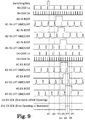
- a switching control from the fast-opening cam 25 to the standard exhaust cam 26 will be described with reference to Fig. 9 .
- the horizontal axis represents the time.
- the same items as those of Fig. 7 will not be described.
- Switching Req (switching request signal) is a timing signal representing a switching request from the fast-opening cam 25 to the standard exhaust cam 26.
- First EX-SOL is a signal representing the capacity of a current applied to the first electromagnetic solenoid 42A of the exhaust-side electromagnetic solenoid 24.
- Second EX-SOL is a signal representing the capacity of a current applied to the second electromagnetic solenoid 42B of the exhaust-side electromagnetic solenoid 24.
- the exhaust cam is switched from the fast-opening cam 25 to the standard exhaust cam 26, and thus a current is applied to the second electromagnetic solenoid 42B of the exhaust-side electromagnetic solenoid 24.
- the ECU 3 monitors the switching request signal and recognizes that a switching request from the fast-opening cam 25 to the standard exhaust cam 26 is given based on a change in the voltage level of the switching request signal. In the example of Fig. 9 , the ECU 3 recognizes that the switching request is given at a falling timing (time t21) from an H-level to an L-level.
- the ECU 3 sequentially makes the intake valve V1 each of the cylinders #1 to #3 rest. Therefore, in a case where the ECU 3 recognizes that an intake control start timing of the next period is reached based on the timing signal IN-CAM1x (at time t22), the ECU 3 sequentially applies a current to the electromagnetic solenoid 55 for resting corresponding to the intake valve V1 of the first cylinder #1, the electromagnetic solenoid 55 for resting corresponding to the intake valve V1 of the second cylinder #2, and the electromagnetic solenoid 55 for resting corresponding to the intake valve V1 of the third cylinder #3 based on the timing signal IN-CAM3x. As a result, regarding the first cylinder #1, the second cylinder #2, and the third cylinder #3, even in a case where the rocker arm 51 swings, the intake valve V1 is maintained in a closed state.
- the ECU sequentially stops current carrying to the electromagnetic solenoid 55 for resting corresponding to the intake valve V1 of the first cylinder #1, the electromagnetic solenoid 55 for resting corresponding to the intake valve V1 of the second cylinder #2, and the electromagnetic solenoid 55 for resting corresponding to the intake valve V1 of the third cylinder #3, and the intake valve V1 is switched to an operation state.
- the ECU 3 recognizes that an intake control start timing of the next period is reached based on the timing signal IN-CAM1x (at time t22), the ECU 3 recognizes that an exhaust control start timing of the next period is reached based on the timing signal EX-CAM1x.
- the intake control of the next period and the exhaust control of the next period are an intake control and an exhaust control in the same combustion cycle.
- the ECU 3 recognizes that an exhaust control start timing of the next period is reached based on the timing signal EX-CAM1x (time t23), the ECU 3 applies a current to the electromagnetic solenoid 55 for resting corresponding to the exhaust valve V2 of the first cylinder #1 based on the timing signal EX-CAM3x (time t24).
- the first cylinder #1 even in a case where the rocker arm 51 swings, the exhaust valve V2 is maintained in a closed state.
- the ECU 3 applies a current to the electromagnetic solenoid 55 for resting corresponding to the exhaust valve V2 of the second cylinder #2 based on the timing signal EX-CAM3x (time t25).
- the ECU 3 applies a current to the electromagnetic solenoid 55 for resting corresponding to the exhaust valve V2 of the third cylinder #3 based on the timing signal EX-CAM3x (time t26).
- the exhaust valve V2 is maintained in a closed state.
- the exhaust valve V2 of each of the cylinders #1 to #3 is made to rest.
- the ECU 3 starts applying a current to the second electromagnetic solenoid 42B of the exhaust-side electromagnetic solenoid 24 at time t26.
- the second switching pin 41B moves down such that the lower end portion is fitted to the second slide groove of the exhaust-side slide groove 23.
- the outer cam shaft of the exhaust-side dual cam shaft 22 starts sliding along the second slide groove, that is, starts sliding in the angle range from the cam angle ⁇ 12 to the cam angle ⁇ 13 such that a relative position between the exhaust cam 21 and the rocker roller 51A changes.
- the exhaust cam 21 is moved such that a part of the rocker roller 51A is positioned on the standard exhaust cam 26 from a state where the rocker roller 51A and the fast-opening cam 25 are in contact with each other.
- the cam lift amount of the fast-opening cam 25 is greater than that of the standard exhaust cam 26. That is, the standard exhaust cam 26 is positioned at a position (position close to the rotation center) lower than the fast-opening cam 25. Therefore, the exhaust cam 21 can be smoothly slid without being hindered by a step difference between a cam surface of the fast-opening cam 25 and a cam surface of the standard exhaust cam 26. The opening and closing operation of the exhaust valve V2 included in each of the cylinders is stopped.
- the cam lift amounts of the exhaust cams 21 of the second cylinder #2 and the third cylinder #3 are zero in the angle range of the cam angle ⁇ 12 to the cam angle ⁇ 13. That is, the base circles of the exhaust cams 21 come into contact with the rocker roller 51A. Therefore, the exhaust cams 21 of the second cylinder #2 and the third cylinder #3 can be switched from the fast-opening cam 25 to the standard exhaust cam 26.
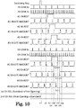
- Switching Req (switching request signal) is a timing signal representing a switching request from the standard intake cam 15 to the low-speed cam 16.
- the ECU 3 monitors the switching request signal and recognizes that a switching request from the standard exhaust cam 26 to the fast-opening cam 25 is given based on a change in the voltage level of the switching request signal. In the example of Fig. 10 , the ECU 3 recognizes that the switching request is given at a falling timing (time t31) from an H-level to an L-level.
- the ECU 3 sequentially makes each of the cylinders #1 to #3 rest. Therefore, in a case where the ECU 3 recognizes that an intake control start timing of the next period is reached based on the timing signal IN-CAM1x (at time t32), the ECU 3 sequentially applies a current to the electromagnetic solenoid 55 for resting corresponding to the intake valve V1 of the first cylinder #1, the electromagnetic solenoid 55 for resting corresponding to the intake valve V1 of the second cylinder #2, and the electromagnetic solenoid 55 for resting corresponding to the intake valve V1 of the third cylinder #3 based on the timing signal IN-CAM3x. As a result, regarding the first cylinder #1, the second cylinder #2, and the third cylinder #3, even in a case where the rocker arm 51 swings, the intake valve V1 is maintained in a closed state.
- the ECU sequentially stops current carrying to the electromagnetic solenoid 55 for resting corresponding to the intake valve V1 of the first cylinder #1, the electromagnetic solenoid 55 for resting corresponding to the intake valve V1 of the second cylinder #2, and the electromagnetic solenoid 55 for resting corresponding to the intake valve V1 of the third cylinder #3, and the intake valve V1 is switched to an operation state.
- the ECU 3 recognizes that an intake control start timing of the next period is reached based on the timing signal IN-CAM1x (at time t32), the ECU 3 recognizes that an exhaust control start timing of the next period is reached based on the timing signal EX-CAM1x.
- the intake control of the next period and the exhaust control of the next period are an intake control and an exhaust control in the same combustion cycle.
- the ECU 3 In a case where the ECU 3 recognizes that an exhaust control start timing of the next period is reached based on the timing signal EX-CAM1x (at time t33), the ECU 3 sequentially makes each of the cylinders rest. Therefore, the ECU 3 applies a current to the electromagnetic solenoid 55 for resting corresponding to the exhaust valve V2 of each of the cylinders #1 to #3 based on the timing signal EX-CAM3x (times t34 to t36).
- the ECU 3 starts applying a current to the first electromagnetic solenoid 42A at time t36.
- the first switching pin 41A moves down such that the lower end portion is fitted to the first slide groove of the exhaust-side slide groove 23.
- the outer cam shaft of the exhaust-side dual cam shaft 22 starts sliding along the first slide groove, that is, starts sliding in the angle range from the cam angle ⁇ 13 to the cam angle ⁇ 14 such that a relative position between the exhaust cam 21 and the rocker roller 51A changes.
- the exhaust cam 21 is moved such that a part of the rocker roller 51A is positioned on the fast-opening cam 25 from a state where the rocker roller 51A and the standard exhaust cam 26 are in contact with each other.
- the cam lift amount of the standard exhaust cam 26 is greater than that of the fast-opening cam 25. That is, the fast-opening cam 25 is positioned at a position (position close to the rotation center) lower than the standard exhaust cam 26. Therefore, the exhaust cam 21 can be smoothly slid without being hindered by a step difference between a cam surface of the standard exhaust cam 26 and a cam surface of the fast-opening cam 25. The opening and closing operation of the exhaust valve V2 included in each of the cylinders is stopped.
- the cam lift amounts of the exhaust cams 21 of the second cylinder #2 and the third cylinder #3 are zero in the angle range of the cam angle ⁇ 13 to the cam angle ⁇ 14. That is, the base circles of the exhaust cams 21 come into contact with the rocker roller 51A. Therefore, the exhaust cams 21 of the second cylinder #2 and the third cylinder #3 can be smoothly switched to the fast-opening cams 25 as long as at least a part of the rocker roller 51A is positioned on the fast-opening cam 25 up to the cam angle ⁇ 14.
- the engine 100 includes the cam switching mechanism 1 that selectively switches between a pair of cams included in the intake cam 11 or the exhaust cam 21 according to an operation state of the engine 100.
- the cylinder resting mechanism 2 that stops the opening and closing operations of the intake and exhaust valves V1 and V2 to make the cylinder rest is provided.
- the cam profile of the standard intake cam 15 included in the intake cam 11 or the fast-opening cam 25 (the first cam) included in the exhaust cam 21 , and the cam profile of the low-speed cam 16 included in the intake cam 11 or the standard exhaust cam 26 (the second cam) included in the exhaust cam 21 are determined, respectively, such that the first cam angle range where the valve lift amounts of the standard intake cam 15 and the fast-opening cam 25 are greater than those of the low-speed cam 16 and the standard exhaust cam 26 and the second cam angle range where the valve lift amounts of the low-speed cam 16 and the standard exhaust cam 26 are greater than those of the standard intake cam 15 and the fast-opening cam 25 are formed
- the set (cylinder resting unit) of the cylinder resting mechanism 2 and the ECU 3 controls to stop the opening and closing operations of the intake and exhaust valves V1 and V2, and the set (cam switching unit) of the cam switching mechanism 1 and the ECU 3 controls to start sliding the outer cam shaft 32 in the first cam angle range that is set for the first cam and the second cam corresponding to one cylinder and is a range where valve lift amounts of the first cam and the second cam corresponding to another cylinder are zero.
- the set of the cylinder resting mechanism 2 and the ECU 3 controls to stop the opening and closing operations of the intake and exhaust valves V1 and V2, and the set of the cam switching mechanism 1 and the ECU 3 controls to start sliding the outer cam shaft 32 in the second cam angle range that is set for the first cam and the second cam corresponding to one cylinder and is a range where valve lift amounts of the first cam and the second cam corresponding to another cylinder are zero.
- the intake cam 11 or the exhaust cam 21 can be slide without being hindered by the step difference between the standard intake cam 15 and the low-speed cam 16 or the step difference between the fast-opening cam 25 and the standard exhaust cam 26.
- switching between the cams can be performed even in a case where the angle range of the base circle is insufficient for switching between the cams.
- the exhaust cam 21 when the exhaust cam 21 is switched, the operations of the intake valve V1 and the exhaust valve V2 relating to the same combustion cycle are stopped. As a result, the piston does not move while the taken air remains in the combustion chamber without being exhausted. Therefore, an increase in the rotational resistance of the engine can be prevented, and deterioration of fuel efficiency can be prevented.
- the taken air is not exhausted from the combustion chamber, and the intake step of the next combustion cycle is not performed. Therefore, in the intake step of the next combustion cycle, air which is taken in does not collide against air which escapes from the inside of the combustion chamber to the intake side, and the generation of an abnormal sound can be appropriately prevented.
- the cam profiles are determined such that a cam angle at which the valve lift amounts of the first cam and the second cam corresponding to another cylinder are not zero is present in the first cam angle range (the second cam angle range) of the first cam and the second cam corresponding to one cylinder. Therefore, the outer cam shaft starts sliding in a range narrower than the first cam angle range (second cam angle range).
- the outer cam shaft can start sliding at any angle in the first cam angle range (the second cam angle range).
- the engine 100 is not limited to a three-cylinder engine as long as it includes plural cylinders.
- the present invention is applicable to a configuration in which an angle range of a base circle is insufficient for switching between cams in terms of cam profiles.
- the cylinder resting mechanism 2 is not limited to the example of the embodiment. The present invention is applicable to any cylinder resting mechanism as long as the cylinder resting mechanism can make each of cylinders rest.
- the dual cam shaft including the outer cam shaft 32 that is movable in the axis direction on the outer periphery of the inner cam shaft 31 is adopted, but the present invention is not limited thereto.
- the first cam and the second cam are provided to be rotatable together, and may have any structure as long as they are movable in the axis direction.
- the cam-switching device and the method of controlling the cam-switching device according to the present disclosure are useful in that switching between cams can be performed even in a case where an angle range of a base circle is insufficient for switching between the cams.
Landscapes
- Engineering & Computer Science (AREA)
- Mechanical Engineering (AREA)
- General Engineering & Computer Science (AREA)
- Chemical & Material Sciences (AREA)
- Combustion & Propulsion (AREA)
- Valve Device For Special Equipments (AREA)
- Output Control And Ontrol Of Special Type Engine (AREA)
Abstract
Description
- The present disclosure relates to a cam-switching device and particularly relates to a cam-switching device that selectively switches between a pair of cams having different cam profiles which are provided corresponding to each of intake and exhaust valves of an engine to make valve characteristics of the intake and exhaust valves variable, and a method of controlling the cam-switching device.
- In the related art, a cam-switching device is well known in which two kinds of cams having different cam profiles are provided in a cam shaft, and the cam shaft is slid in an axis direction by a hydraulic actuator to selectively switch between the cams such that valve characteristics of intake and exhaust valves are variable (for example, refer to
patent literatures 1 and 2). - The intake and exhaust valves are typically urged in valve closing directions by valve springs, respectively, and are opened when a rocker arm that swings by the cams presses the intake and exhaust valves against a restoring force of the valve springs. That is, in a cylinder operation during which the intake and exhaust valves are opened and closed, a contact pressure is applied between the cams and the rocker arm. Therefore, switching between the cams is performed on a base circle of each of the cams where the intake and exhaust valves are not lifted.
-
- [Patent Literature 1]:
JP-A-2002-4823 - [Patent Literature 2]:
JP-A-2001-123811 - The cam-switching device that switches between the cams is required to be provided on each of the intake side and the exhaust side. Therefore, in a case where the cam-switching device is provided per cylinder, the number of cam-switching devices is necessarily two times the number of cylinders, and a configuration thereof is complicated.
- Therefore, a configuration of providing the switching device on each of the intake side and the exhaust side and collectively operating the intake side of the plural cylinders and the exhaust side of the plural cylinders is considered. However, an opening and closing timing of a valve is determined per cylinder. Therefore, depending on the number of cylinders or the cam profiles, an angle range of a base circle may be insufficient for switching between the cams. For example, in a case where opening and closing periods of the intake and exhaust valves correspond to an angle range of 120° on the cams, a phase is 120° in a three-cylinder engine. In this case, intake and exhaust valves corresponding to any one of the cylinders are lifted. Therefore, it is difficult to collectively switch between cams corresponding to three cylinders.
- An aspect of the present disclosure has been made in consideration of the above-described circumstances, and an object thereof is to provide a cam-switching device and a method of controlling the cam-switching device, in which switching between cams can be performed even in a case where an angle range of a base circle is insufficient for switching between the cams.
- According to an aspect of the present disclosure for achieving the object, there is provided a cam-switching device that selectively switch es between a first cam and a second cam to make valve characteristics of intake and exhaust valves of an engine variable,
the first cam and the second cam being provided corresponding to each of the intake and exhaust valves and having different cam profiles,
each of the cam profiles being determined such that a first cam angle range where a valve lift amount of the first cam is greater than a valve lift amount of the second cam and a second cam angle range where a valve lift amount of the second cam is greater than a valve lift amount of the first cam are formed, and
the cam-switching device including: - a cam shaft configured to rotate in conjunction with a crank shaft of the engine and provided such that the first cam and the second cam are rotatable together;
- a cam shaft moving unit configured to slide the cam shaft in an axis direction to selectively switch between the first cam and the second cam;
- a cylinder resting unit configured to stop opening and closing operations of the intake and exhaust valves to make a cylinder restable; and
- a cam shaft moving control unit configured to control the cylinder resting unit to stop the opening and closing operations of the intake and exhaust valves in the same combustion cycle and control the cam shaft moving unit to start sliding the cam shaft in the first cam angle range in a case of switching from the first cam to the second cam, and to control the cylinder resting unit to stop the opening and closing operations of the intake and exhaust valves in the same combustion cycle and control the cam shaft moving unit to start sliding the cam shaft in the second cam angle range in a case of switching from the second cam to the first cam.
- The cam-switching device may further include a rocker arm configured to swing according to the cam profiles of the first cam and the second cam and presses the intake and exhaust valves against a restoring force of a valve spring,
in which the cylinder resting unit may cause the rocker arm to swing around a point contacting the intake and exhaust valves as a fulcrum. - In addition, in the cam-switching device, the engine may be an inline multi-cylinder engine in which plural cylinders are arranged in line,
the first cam and the second cam may be provided corresponding to each of the intake and exhaust valves of the plural cylinders,
the cam shaft moving control unit may control the cylinder resting unit to stop the opening and closing operations of the intake and exhaust valves provided in the plural cylinders in the same combustion cycle , and may control the cam shaft moving unit to start sliding the cam shaft in an axis direction in the first cam angle range that is set for the first cam and the second cam corresponding to one cylinder and is a range where valve lift amounts of the first cam and the second cam corresponding to another cylinder are zero, in a case of switching from the first cam to the second cam, and
the cam shaft moving control unit may control the cylinder resting unit to stop the opening and closing operations of the intake and exhaust valves provided in the plural cylinders in the same combustion cycle , and may control the cam shaft moving unit to start sliding the cam shaft in an axis direction in the second cam angle range that is set for the first cam and the second cam corresponding to one cylinder and is a range where valve lift amounts of the first cam and the second cam corresponding to another cylinder are zero, in a case of switching from the second cam to the first cam. - According to another aspect of the present disclosure for achieving the object, there is provided a method of controlling a cam-switching device including a first cam and a second cam provided corresponding to each of intake and exhaust valves of an engine and having different cam profiles, each of the cam profiles being determined such that a first cam angle range where a valve lift amount of the first cam is greater than a valve lift amount of the second cam and a second cam angle range where a valve lift amount of the second cam is greater than a valve lift amount of the first cam are formed, a cam shaft configured to rotate in conjunction with a crank shaft of the engine and provided such that the first cam and the second cam are rotatable together, a cam shaft moving unit configured to slide the cam shaft in an axis direction to selectively switch between the first cam and the second cam, and a cylinder resting unit configured to stop opening and closing operations of the intake and exhaust valves to make a cylinder restable, the method including:
- a step of controlling the cylinder resting unit to stop the opening and closing operations of the intake and exhaust valves in the same combustion cycle and controlling the cam shaft moving unit to start sliding the cam shaft in the first cam angle range in a case of switching from the first cam to the second cam; and
- a step of controlling the cylinder resting unit to stop the opening and closing operations of the intake and exhaust valves in the same combustion cycle and controlling the cam shaft moving unit to start sliding the cam shaft in the second cam angle range in a case of switching from the second cam to the first cam.
- With the cam-switching device and the method of controlling the cam-switching device according to the present disclosure, switching between cams can be performed even in a case where an angle range of a base circle is insufficient for switching between the cams.
-
-
Fig. 1 is a schematic perspective view illustrating a configuration of an upper part of an engine block in a state where a cylinder head cover is removed. -
Fig. 2 is a schematic perspective view illustrating an external appearance of a dual cam shaft. -
Fig. 3A is a view schematically illustrating the vicinity of an electromagnetic solenoid in a state where a standard intake cam is selected, andFig. 3B is a view schematically illustrating a positional relationship between the standard intake cam and a rocker roller. -
Fig. 4A is a view schematically illustrating the vicinity of the electromagnetic solenoid in a state where a low-speed cam is selected, andFig. 4B is a view schematically illustrating a positional relationship between the low-speed cam and the rocker roller. -
Fig. 5 is a schematic cross-sectional view illustrating a configuration of intake and exhaust valves and the vicinity thereof. -
Fig. 6A is a diagram schematically illustrating a relationship between a cam angle and a cam lift amount of an intake cam, andFig. 6B is a diagram schematically illustrating a relationship between a cam angle and a cam lift amount of an exhaust cam. -
Fig. 7 is a timing chart illustrating switching from the standard cam to the low-speed cam in the intake cam. -
Fig. 8 is a timing chart illustrating switching from the low-speed cam to the standard cam in the intake cam. -
Fig. 9 is a timing chart illustrating switching from a fast-opening cam to a standard cam in the exhaust cam. -
Fig. 10 is a timing chart illustrating switching from the standard cam to the fast-opening cam in the exhaust cam. - Hereinafter, an embodiment of the present disclosure will be described with reference to the accompanying drawings. An
engine 100 illustrated inFig. 1 is, for example, an inline three-cylinder engine, and includes acam switching mechanism 1 that selectively switches between a pair of cams (described below) according to an operation state of theengine 100. In addition, in each of cylinders of theengine 100, acylinder resting mechanism 2 that stops opening and closing operations of intake and exhaust valves to make the cylinder rest is provided. One set of thecam switching mechanism 1, thecylinder resting mechanism 2, and an electronic control unit (ECU) 3 that controls operations of the cam switching mechanism and the cylinder resting mechanism is an example of the cam-switching device according to the present disclosure. For example, theECU 3 includes a CPU, a ROM, a RAM, an input port, an output port, and the like as well-known. The ECU 3 is an example of the cam shaft moving control unit. A part of functional elements of the ECU 3 can also be provided in separate hardware. - The
cam switching mechanism 1 includes an intake-sidecam switching mechanism 10 and an exhaust-sidecam switching mechanism 20. The intake-sidecam switching mechanism 10 includes: an intake-sidedual cam shaft 12 in which anintake cam 11 is provided; and an intake-side slide groove (refer toFigs. 3A and 3B ) 13 and an intake-sideelectromagnetic solenoid 14 that slide the intake-sidedual cam shaft 12. The exhaust-sidecam switching mechanism 20 includes: an exhaust-sidedual cam shaft 22 in which anexhaust cam 21 is provided; and an exhaust-side slide groove 23 and an exhaust-sideelectromagnetic solenoid 24 that slide the exhaust-sidedual cam shaft 22. - Among these, a set of the intake-
side slide groove 13 and the intake-sideelectromagnetic solenoid 14 and a set of the exhaust-side slide groove 23 and the exhaust-sideelectromagnetic solenoid 24 configure an example of the cam shaft moving unit according to the present disclosure together with theECU 3. In addition, theintake cam 11 provided in the intake-sidedual cam shaft 12 includes two kinds of cams (astandard intake cam 15 and a low-speed cam 16) having different cam profiles. Theexhaust cam 21 provided in the exhaust-sidedual cam shaft 22 includes two kinds of cams (a fast-openingcam 25 and a standard exhaust cam 26) having different cam profiles. Thestandard intake cam 15 and the fast-openingcam 25 are examples of the first cam according to the present disclosure, and the low-speed cam 16 and thestandard exhaust cam 26 are examples of the second cam according to the present disclosure. - The respective portions included in the exhaust-side
cam switching mechanism 20, the exhaust-sidedual cam shaft 22, the exhaust-side slide groove 23, and the exhaust-sideelectromagnetic solenoid 24 have the same configurations as the respective portions of the intake-sidecam switching mechanism 10, except that theexhaust cam 21 as a switching target includes the fast-openingcam 25 and thestandard exhaust cam 26. Therefore, hereinafter, the intake-sidecam switching mechanism 10 will be described, and the description of the exhaust-sidecam switching mechanism 20 will not be made. - As illustrated in
Fig. 2 , the intake-sidedual cam shaft 12 includes: aninner cam shaft 31 that rotates in conjunction with a crank shaft (not illustrated) of theengine 100; and anouter cam shaft 32 that is spline-fitted to an outer periphery of theinner cam shaft 31 and is slidable in an axis direction relative to theinner cam shaft 31. -
Plural intake cams 11 are press-fitted into theouter cam shaft 32 and are attached thereto in a state where they are rotatable together with theouter cam shaft 32. As illustrated inFig. 1 , in theengine 100 according to the embodiment, one cylinder includes two intake valves, and thus six intake valves and sixintake cams 11 are provided in total. As illustrated inFig. 2 , each of theintake cams 11 includes thestandard intake cam 15 and the low-speed cam 16. By moving theouter cam shaft 32 in the axis direction of theinner cam shaft 31, any one of thestandard intake cam 15 and the low-speed cam 16 can be selected. Twointake cams 11 corresponding to the same cylinder are attached such that cam profiles thereof have the same phase. Since the number of cylinders is three, three sets ofintake cams 11 are attached in a state where the phases are shifted from each other by 120° per cylinder. - In an end portion of the
outer cam shaft 32, two intake-side slide grooves 13 (afirst slide groove 13A and asecond slide groove 13B) are provided. Shapes of theslide grooves outer cam shaft 32 starts sliding when cam angles thereof are in predetermined angle ranges described below, respectively. When theouter cam shaft 32 slides in the axis direction of theinner cam shaft 31, switchingpins electromagnetic solenoid 14 are fitted into theslide grooves Figs. 3A and4A ). - As illustrated in
Fig. 3A , when thestandard intake cam 15 is selected, thefirst switching pin 41A positioned on the left side inFig. 3A moves downward such that a lower end portion of thefirst switching pin 41A is fitted to thefirst slide groove 13A. As a result, as illustrated inFig. 3B , theouter cam shaft 32 slides to the right side inFig. 3B such that thestandard intake cam 15 included in theintake cam 11 comes into contact with arocker roller 51A. As illustrated inFig. 4A , when the low-speed cam 16 is selected, thesecond switching pin 41B positioned on the left side inFig. 4A moves downward such that a lower end portion of thesecond switching pin 41B is fitted to thesecond slide groove 13B. As a result, as illustrated inFig. 4B , theouter cam shaft 32 slides to the left side inFig. 4B such that the low-speed cam 16 included in theintake cam 11 comes into contact with therocker roller 51A. - As illustrated in
Figs. 3A and4A , the movement of thefirst switching pin 41A and thesecond switching pin 41B in the up-down direction is controlled by the intake-sideelectromagnetic solenoid 14. Specifically, the movement is controlled by applying a current to a firstelectromagnetic solenoid 42A positioned on thefirst switching pin 41A and a secondelectromagnetic solenoid 42B positioned on thesecond switching pin 41B. - A
first iron core 43A is disposed at the center of the firstelectromagnetic solenoid 42A, and a lower end of thefirst iron core 43A is an N pole during current carrying to the firstelectromagnetic solenoid 42A. In an upper end portion of thefirst switching pin 41A, a firstpermanent magnet 44A having an upper surface as an N pole is provided. Likewise, asecond iron core 43B is disposed at the center of the secondelectromagnetic solenoid 42B, and a lower end of thesecond iron core 43B is an S pole during current carrying to the secondelectromagnetic solenoid 42B. In an upper end portion of thesecond switching pin 41B, a secondpermanent magnet 44B having an upper surface as an S pole is provided. Further, upper end portions of thefirst iron core 43A and thesecond iron core 43B connected to each other through ayoke 45 formed of a plate-shaped magnetic permeable material. - As illustrated in
Fig. 3A , in a case where a current is applied to the firstelectromagnetic solenoid 42A and current carrying to the secondelectromagnetic solenoid 42B is stopped, the lower end of thefirst iron core 43A is an N pole and is repulsive against the firstpermanent magnet 44A. Therefore, thefirst switching pin 41A moves downward. On the other hand, in a case where current carrying to the secondelectromagnetic solenoid 42B is stopped, the lower end of thesecond iron core 43B is magnetized into an N pole by a magnetic field from thefirst iron core 43A and is attracted to the secondpermanent magnet 44B. Therefore, thesecond switching pin 41B is adsorbed on the lower end of thesecond iron core 43B. - As illustrated in
Fig. 4A , in a case where a current is applied to the secondelectromagnetic solenoid 42B and current carrying to the firstelectromagnetic solenoid 42A is stopped, the lower end of thesecond iron core 43B is an S pole and is repulsive against the secondpermanent magnet 44B. Therefore, thesecond switching pin 41B moves downward. On the other hand, current carrying to the firstelectromagnetic solenoid 42A is stopped, and the lower end of thefirst iron core 43A is magnetized to an S pole by a magnetic field from thesecond iron core 43B and is attracted to the firstpermanent magnet 44A. Therefore, thefirst switching pin 41A is adsorbed on the lower end of thefirst iron core 43A. - Accordingly, by selectively performing the current carrying to the first
electromagnetic solenoid 42A and the current carrying to the secondelectromagnetic solenoid 42B, thefirst switching pin 41A and thesecond switching pin 41B can be selectively fitted to thefirst slide groove 13A and thesecond slide groove 13B, and thestandard intake cam 15 and the low-speed cam 16 can be selectively brought into contact with therocker roller 51A. - Next, the
cylinder resting mechanism 2 will be described. Thecylinder resting mechanism 2 is a mechanism that closes the intake and exhaust valves to make the cylinder rest, and configures the cylinder resting unit according to the present disclosure together with theECU 3. As illustrated inFig. 5 , thecylinder resting mechanism 2 includes arocker arm 51, abracket 52, ahydraulic tappet 53, aneedle 54, and anelectromagnetic solenoid 55 for resting. - The
rocker arm 51 is a member that is swung by the intake cam 11 (thestandard intake cam 15 and the low-speed cam 16) or the exhaust cam 21 (thestandard exhaust cam 26 and the fast-opening cam 25) to operate an intake valve V1 or an exhaust valve V2 in a valve opening direction. One end portion of therocker arm 51 is attached in a state where it is rotatable around therocker shaft axis 51B with respect to thebracket 52. The other end portion of therocker arm 51 comes into contact with an upper end of the intake valve V1 or the exhaust valve V2 from above. Therocker roller 51A contacting theintake cam 11 or theexhaust cam 21 may be formed in the middle of therocker arm 51 in a longitudinal direction. - The
bracket 52 is a member that is connected to therocker arm 51 on therocker shaft axis 51B by pin-connection and moves up and down according to the swinging of therocker arm 51 in a state where the cylinder rests. Theneedle 54 is stored in thebracket 52, and aneedle storage space 52A filled with engine oil is formed in thebracket 52. A lower portion of thebracket 52 forms apiston portion 52B having a bottomed cylindrical shape that advances and retreats relative to thehydraulic tappet 53. In a bottom surface center portion of thepiston portion 52B, anoil gallery 52C that forms a passage of the engine oil and into which a tip portion of theneedle 54 is inserted is formed in a state where it penetrates the bottom surface center portion in a plate thickness direction. In addition, in a side surface of thepiston portion 52B, acommunication hole 52D through which an oil passage OL and theneedle storage space 52A filled with the engine oil is formed. - The
hydraulic tappet 53 is a member into which thepiston portion 52B of thebracket 52 is retreatably inserted and that supports the bracket 52 (thepiston portion 52B) from below, and includes: acylindrical body 53A; acheck ball 53B that is urged upward by a check ball spring (not illustrated); astorage portion 53C having a bottomed cylindrical shape that comes into contact with a lower end surface of thepiston portion 52B and stores thecheck ball 53B and the check ball spring; apiston spring 53D that supports thestorage portion 53C from below. - In a state where the cylinder operates, in the
hydraulic tappet 53, thecheck ball 53B is urged upward such that theoil gallery 52C of thepiston portion 52B is blocked by thecheck ball 53B. In a state where theoil gallery 52C is blocked, the engine oil that fills a region below thepiston portion 52B cannot flow. Therefore, the bracket 52 (thepiston portion 52B) cannot move down, and a position thereof in a height direction is fixed. - On the other hand, in a state where the cylinder rests, in the
hydraulic tappet 53, thecheck ball 53B is moved down by theneedle 54 such that theoil gallery 52C of thepiston portion 52B is opened. In a state where theoil gallery 52C is opened, the engine oil that fills a region below thepiston portion 52B can flow to the inside of theneedle storage space 52A through theoil gallery 52C. The engine oil in theneedle storage space 52A can flow to the oil passage OL from thecommunication hole 52D that is formed in the side surface of thepiston portion 52B. Therefore, in a case where theoil gallery 52C is opened, the bracket 52 (piston portion 52B) can move down. That is, in a case where a pressing force of thecams piston spring 53D, thepiston spring 53D contracts such that thebracket 52 moves down. In a case where the pressing force of thecams piston spring 53D, thebracket 52 moves up by the restoring force of thepiston spring 53D. - The
needle 54 is a rod-shaped member for moving thecheck ball 53B down and is stored in theneedle storage space 52A of thebracket 52 in a state where it is movable in the axis direction, and a lower end thereof is in contact with thecheck ball 53B. An upper end portion of theneedle 54 is stored in theelectromagnetic solenoid 55 for resting, and moves in the up-down direction by aplunger 55C included in theelectromagnetic solenoid 55 for resting. - The
electromagnetic solenoid 55 for resting includes aguide shaft 55A, acoil 55B for resting, and theplunger 55C. - The
guide shaft 55A is a cylindrical member having a blocked upper end, in which aplunger storage space 55D that stores theplunger 55C in a state where it is movable in the axis direction of theneedle 54 is formed in an upper end portion, and aneedle storage space 55E that stores theneedle 54 in a state where it is movable in the axis direction is formed below thestorage space 55D. Further, in a lower end portion of theguide shaft 55A, aguide space 55F to which an upper end portion of thebracket 52 is fitted in a state where it is slidable in the axis direction of theneedle 54 is formed. - The
coil 55B for resting is disposed in an upper end portion of theguide shaft 55A and urges theplunger 55C downward by applying a current to generate a magnetic field. Theplunger 55C comes into contact with the upper end of theneedle 54 from above, and presses theneedle 54 down by the magnetic field generated from thecoil 55B for resting. In a case where the current carrying to thecoil 55B for resting is stopped, the generation of the magnetic field is stopped. Therefore, thecheck ball 53B is moved up by the restoring force of the check ball spring, and thus theneedle 54 and theplunger 55C are also moved up. - In the
cylinder resting mechanism 2 having the above-described configuration, current carrying to theelectromagnetic solenoid 55 for resting (thecoil 55B for resting) is stopped in a state where the cylinder operates, and a current is applied to theelectromagnetic solenoid 55 for resting in a state where the cylinder rests. - In a state where current carrying to the
electromagnetic solenoid 55 for resting is stopped, thecheck ball 53B is moved up such that theoil gallery 52C of thepiston portion 52B is blocked. As a result, the height position of thebracket 52 is fixed. In a case where therocker roller 51A is pressed along the cam profile of theintake cam 11 or theexhaust cam 21, one end portion of therocker arm 51 rotates around therocker shaft axis 51B as a fulcrum, and the other end portion of therocker arm 51 swings against a restoring force of the valve spring SP. As a result, the intake valve V1 or the exhaust valve V2 is opened or closed. - In a state where a current is applied to the
electromagnetic solenoid 55 for resting, thecheck ball 53B is moved down such that theoil gallery 52C of thepiston portion 52B is opened. As a result, thebracket 52 is movable in the up-down direction (the axis direction of the needle 54). In a case where therocker roller 51A is pressed along the cam profile of theintake cam 11 or theexhaust cam 21, the restoring force of the valve spring SP is strong. Therefore, the other end portion of therocker arm 51 rotates around an upper end of the intake valve V1 or an upper end of the exhaust valve V2 as a fulcrum, and the one end portion of therocker arm 51 swings in the up-down direction through therocker shaft axis 51B together with thebracket 52. Therefore, even in a case where therocker arm 51 swings, the intake valve V1 or the exhaust valve V2 is maintained in a closed state. - Next, the cam profiles of the
intake cam 11 and theexhaust cam 21 will be described with reference toFigs. 6A and 6B . - As illustrated in
Fig. 6A , in theintake cam 11 of afirst cylinder # 1, in an angle range from a cam angle θ1 to a cam angle θ3, acam profile # 1instd of thestandard intake cam 15 has a greater cam lift amount than acam profile # 1inLow of the low-speed cam 16. On the other hand, in an angle range from a cam angle θ3 to a cam angle θ5, thecam profile # 1inLow of the low-speed cam 16 has a greater cam lift amount than thecam profile # 1instd of thestandard intake cam 15. - In the
intake cam 11 of asecond cylinder # 2, in an angle range from a cam angle θ4 to a cam angle θ6, acam profile # 2instd of thestandard intake cam 15 has a greater cam lift amount than acam profile # 2inLow of the low-speed cam 16. On the other hand, in an angle range from a cam angle θ6 to a cam angle θ8, thecam profile # 2inLow of the low-speed cam 16 has a greater cam lift amount than thecam profile # 2instd of thestandard intake cam 15. - In the
intake cam 11 of athird cylinder # 3, in an angle range from a cam angle θ7 to a cam angle θ9, acam profile # 3instd of thestandard intake cam 15 has a greater cam lift amount than acam profile # 3inLow of the low-speed cam 16. On the other hand, in an angle range from a cam angle θ9 to a cam angle θ10, thecam profile # 3inLow of the low-speed cam 16 has a greater cam lift amount than thecam profile # 3instd of thestandard intake cam 15. - It can be seen from
Fig. 6A that, even when any cam angle is selected in theintake cam 11 according to the embodiment, the intake valve V1 of any one of the cylinders is lifted and an angle range of a base circle included in theintake cam 11 is insufficient for switching between thestandard intake cam 15 and the low-speed cam 16. - In the example of
Fig. 6A , the angle range from the cam angle θ1 to the cam angle θ3, the angle range from the cam angle θ4 to the cam angle θ6, and the angle range from the cam angle θ7 to the cam angle θ9 correspond to the first angle range according to the present disclosure. In addition, the angle range from the cam angle θ3 to the cam angle θ5, the angle range from the cam angle θ6 to the cam angle θ8, and the angle range from the cam angle θ9 to the cam angle θ10 correspond to the second angle range according to the present disclosure. In the embodiment, the first angle range includes a range where the cam lift amounts of the other cylinders are not zero. Therefore, during switching from thestandard intake cam 15 to the low-speed cam 16, in the first angle range that is a range where the cam lift amounts of the other cylinders are zero, for example, in the range from the cam angle θ2 to the cam angle θ3 in the case of thefirst cylinder # 1, theouter cam shaft 32 starts sliding. In addition, the second angle range includes a range where the cam lift amounts of the other cylinders are not zero. Therefore, during switching from the low-speed cam 16 to thestandard intake cam 15, in the second angle range that is a range where the cam lift amounts of the other cylinders are zero, for example, in the range from the cam angle θ3 to the cam angle θ4 in the case of thefirst cylinder # 1, theouter cam shaft 32 starts sliding. - As illustrated in
Fig. 6B , in theexhaust cam 21 of thefirst cylinder # 1, in an angle range from a cam angle θ11 to a cam angle θ13, acam profile # 1exfst of the fast-openingcam 25 has a greater cam lift amount than acam profile # 1exstd of thestandard exhaust cam 26. On the other hand, in an angle range from a cam angle θ13 to a cam angle θ15, thecam profile # 1exstd of thestandard exhaust cam 26 has a greater cam lift amount than thecam profile # 1exfst of the fast-openingcam 25. - In the
exhaust cam 21 of thesecond cylinder # 2, in an angle range from a cam angle θ14 to a cam angle θ16, acam profile # 2exfst of the fast-openingcam 25 has a greater cam lift amount than acam profile # 2exstd of thestandard exhaust cam 26. On the other hand, in an angle range from a cam angle θ16 to a cam angle θ18, thecam profile # 2exstd of thestandard exhaust cam 26 has a greater cam lift amount than thecam profile # 2exfst of the fast-openingcam 25. - In the
exhaust cam 21 of thethird cylinder # 3, in an angle range from a cam angle θ17 to a cam angle θ19, acam profile # 3exfst of the fast-openingcam 25 has a greater cam lift amount than acam profile # 3exstd of thestandard exhaust cam 26. On the other hand, in an angle range from a cam angle θ19 to a cam angle θ20, thecam profile # 3exstd of thestandard exhaust cam 26 has a greater cam lift amount than thecam profile # 3exfst of the fast-openingcam 25. - It can be seen from
Fig. 6B that, even when any cam angle is selected in theexhaust cam 21 according to the embodiment, the exhaust valve V2 of any one of the cylinders is lifted and an angle range of a base circle included in theexhaust cam 21 is insufficient for switching between the fast-openingcam 25 and thestandard exhaust cam 26. - In the example of
Fig. 6B , the angle range from the cam angle θ11 to the cam angle θ13, the angle range from the cam angle θ14 to the cam angle θ16, and the angle range from the cam angle θ17 to the cam angle θ19 correspond to the first angle range according to the present disclosure. In addition, the angle range from the cam angle θ13 to the cam angle θ15, the angle range from the cam angle θ16 to the cam angle θ18, and the angle range from the cam angle θ19 to the cam angle θ20 correspond to the second angle range according to the present disclosure. In the embodiment, the first angle range includes a range where the cam lift amounts of the other cylinders are not zero. Therefore, during switching from the fast-openingcam 25 to thestandard exhaust cam 26, in the first angle range that is a range where the cam lift amounts of the other cylinders are zero, for example, in the range from the cam angle θ12 to the cam angle θ13 in the case of thefirst cylinder # 1, the outer cam shaft starts sliding. In addition, the second angle range includes a range where the cam lift amounts of the other cylinders are not zero. Therefore, during switching from thestandard exhaust cam 26 to the fast-openingcam 25, in the second angle range that is a range where the cam lift amounts of the other cylinders are zero, for example, in the range from the cam angle θ13 to the cam angle θ14 in the case of thefirst cylinder # 1, the outer cam shaft starts sliding. - Next, a switching control of the cams using the
ECU 3 will be described. - First, a switching control from the
standard intake cam 15 to the low-speed cam 16 will be described with reference toFig. 7 . In a timing chart ofFig. 7 , the horizontal axis represents the time. The description will be made in order from the upper stage ofFig. 7 . Switching Req (switching request signal) is a timing signal representing a switching request from thestandard intake cam 15 to the low-speed cam 16. The switching request is output as an H-level signal in a case where theECU 3 detects that predetermined conditions are satisfied. IN-CAM1x is a timing signal representing the start of each cycle in a case where an intake control on the three cylinders is set as one cycle. IN-CAM3x is a timing signal representing the start of a control on each of the cylinders in one cycle period. - #1IN-Rest is a control signal that is at an H-level over a cylinder resting period of the intake valve V1 of the
first cylinder # 1. #1 IN-Lift Amount is a signal schematically representing the lift amount of a pair of intake valves V1 provided in thefirst cylinder # 1. #2IN-Rest is a control signal that is at an H-level over a cylinder resting period of the intake valve V1 of thesecond cylinder # 2. #2IN-Lift Amount is a signal schematically representing the lift amount of a pair of intake valves V1 provided in thesecond cylinder # 2. #3IN-Rest is a control signal that is at an H-level over a cylinder resting period of the intake valve V1 of thethird cylinder # 3. #3IN-Lift Amount is a signal schematically representing the lift amount of a pair of intake valves V1 provided in thethird cylinder # 3. - First IN-SOL is a signal representing the capacity of a current applied to the first
electromagnetic solenoid 42A. Second IN-SOL is a signal representing the capacity of a current applied to the secondelectromagnetic solenoid 42B. In the example ofFig. 7 , the intake cam is switched from thestandard intake cam 15 to the low-speed cam 16, and thus a current is applied to the secondelectromagnetic solenoid 42B. - EX-CAM1x is a timing signal representing the start of each cycle in a case where an exhaust control on the three cylinders is set as one cycle. EX-CAM3x is a timing signal representing the start of a control on each of the cylinders in one cycle period.
- #1EX-Rest is a control signal that is at an H-level over a cylinder resting period of the exhaust valve V2 of the
first cylinder # 1. #1EX-Lift Amount is a signal schematically representing the lift amount of a pair of exhaust valves V2 provided in thefirst cylinder # 1. #2EX-Rest is a control signal that is at an H-level over a cylinder resting period of the exhaust valve V2 of thesecond cylinder # 2. #2EX-Lift Amount is a signal schematically representing the lift amount of a pair of exhaust valves V2 provided in thesecond cylinder # 2. #3EX-Rest is a control signal that is at an H-level over a cylinder resting period of the exhaust valve V2 of thethird cylinder # 3. #3EX-Lift Amount is a signal schematically representing the lift amount of a pair of exhaust valves V2 provided in thethird cylinder # 3. - The
ECU 3 monitors the switching request signal and recognizes that a switching request from thestandard intake cam 15 to the low-speed cam 16 is given based on a change in the voltage level of the switching request signal. In the example ofFig. 7 , theECU 3 recognizes that the switching request is given at a falling timing (time t1) from an H-level to an L-level. - In a case where the switching request from the
standard intake cam 15 to the low-speed cam 16 is recognized, theECU 3 sequentially makes each of thecylinders # 1 to #3 rest. Therefore, theECU 3 recognizes that a control start timing of the next period is reached based on the timing signal IN-CAM1x (time t2), and then applies a current to theelectromagnetic solenoid 55 for resting (thecoil 55B for resting) corresponding to the intake valve V1 of thefirst cylinder # 1 based on the timing signal IN-CAM3x (time t3). As a result, regarding thefirst cylinder # 1, even in a case where therocker arm 51 swings, the intake valve V1 is maintained in a closed state. - Next, the
ECU 3 applies a current to theelectromagnetic solenoid 55 for resting corresponding to the intake valve V1 of thesecond cylinder # 2 based on the timing signal IN-CAM3x (time t4). As a result, regarding thesecond cylinder # 2, even in a case where therocker arm 51 swings, the intake valve V1 is maintained in a closed state. Likewise, theECU 3 applies a current to theelectromagnetic solenoid 55 for resting corresponding to the intake valve V1 of thethird cylinder # 3 based on the timing signal IN-CAM3x (time t6). As a result, regarding thethird cylinder # 3, even in a case where therocker arm 51 swings, the intake valve V1 is maintained in a closed state. At time t6, each of thecylinders # 1 to #3 is made to rest. - The
ECU 3 starts applying a current to the secondelectromagnetic solenoid 42B at time t6. By applying a current to the secondelectromagnetic solenoid 42B, thesecond switching pin 41B moves down such that the lower end portion is fitted to thesecond slide groove 13B. As a result, theouter cam shaft 32 starts sliding along thesecond slide groove 13B, that is, starts sliding in the angle range from the cam angle θ2 to the cam angle θ3 such that a relative position between theintake cam 11 and therocker roller 51A changes. Specifically, theintake cam 11 is moved such that a part of therocker roller 51A is positioned on the low-speed cam 16 from a state where therocker roller 51A and thestandard intake cam 15 are in contact with each other. - Here, as illustrated in
Fig. 6A , in the angle range from the cam angle θ2 to the cam angle θ3, the cam lift amount of thestandard intake cam 15 is greater than that of the low-speed cam 16. That is, the low-speed cam 16 is positioned at a position (position close to the rotation center) lower than thestandard intake cam 15. Therefore, theintake cam 11 can be smoothly slid without being hindered by a step difference between a cam surface of thestandard intake cam 15 and a cam surface of the low-speed cam 16. The opening and closing operation of the intake valve V1 included in each of the cylinders is stopped. Therefore, even in a case where therocker roller 51A falls from the step difference between thestandard intake cam 15 and the low-speed cam 16, therocker arm 51 moves in the up-down direction together with thebracket 52 such that the swinging of therocker arm 51 is absorbed. As a result, the cam can be switched while preventing the generation of an abnormal sound. - As can be seen from
Fig. 6A , the cam lift amounts of theintake cams 11 of thesecond cylinder # 2 and thethird cylinder # 3 are zero in the angle range of the cam angle θ2 to the cam angle θ3. That is, the base circles of theintake cams 11 come into contact with therocker roller 51A. Therefore, theintake cams 11 of thesecond cylinder # 2 and thethird cylinder # 3 can be switched from thestandard intake cams 15 to the low-speed cams 16. - Next, as illustrated in
Fig. 7 , at time t7, current carrying to theelectromagnetic solenoid 55 for resting corresponding to the intake valve V1 of thefirst cylinder # 1 is stopped, and the intake valve V1 is switched to an operation state. At this time, at least a part of therocker roller 51A is positioned on the low-speed cam 16. As a result, the opening and closing operation of the intake valve V1 of thefirst cylinder # 1 starts smoothly according to the cam profile of the low-speed cam 16. - Next, at time t8, current carrying to the
electromagnetic solenoid 55 for resting corresponding to the intake valve V1 of thesecond cylinder # 2 is stopped. At time t9, current carrying to theelectromagnetic solenoid 55 for resting corresponding to the intake valve V1 of thethird cylinder # 3 is stopped, and the intake valve V1 included in each of thecylinders # 2 and #3 is switched to an operation state. Regarding thecylinders # 2 and #3, at least a part of therocker roller 51A is positioned on the low-speed cam 16. Therefore, the opening and closing operation of the intake valve V1 starts smoothly according to the cam profile of the low-speed cam 16. - In addition, in a case where the
ECU 3 recognizes that an intake control start timing of the next period is reached based on the timing signal IN-CAM1x (at time t2), the ECU recognizes that an exhaust control start timing of the next period is reached based on the timing signal EX-CAM1x. Here, the intake control of the next period and the exhaust control of the next period are an intake control and an exhaust control in the same combustion cycle. Here, for example, in the case of a four-stroke engine, the combustion cycle refers to a cycle including four steps of an intake step, a compression step, a combustion step, and an exhaust step. In addition, the intake control and the exhaust control in the same combustion cycle refer to an intake control and an exhaust control that are performed in one combustion cycle. - In a case where the
ECU 3 recognizes that an exhaust control start timing of the next period is reached based on the timing signal EX-CAM1x (at time t5), theECU 3 sequentially applies a current to theelectromagnetic solenoid 55 for resting (thecoil 55B for resting) corresponding to the exhaust valve V2 of thefirst cylinder # 1, theelectromagnetic solenoid 55 for resting corresponding to the exhaust valve V2 of thesecond cylinder # 2, and theelectromagnetic solenoid 55 for resting corresponding to the exhaust valve V2 of thethird cylinder # 3 based on the timing signal EX-CAM3x. As a result, regarding thefirst cylinder # 1, thesecond cylinder # 2, and thethird cylinder # 3, even in a case where therocker arm 51 swings, the exhaust valve V2 is maintained in a closed state. - Next, the ECU sequentially stops current carrying to the
electromagnetic solenoid 55 for resting corresponding to the exhaust valve V2 of thefirst cylinder # 1, theelectromagnetic solenoid 55 for resting corresponding to the exhaust valve V2 of thesecond cylinder # 2, and theelectromagnetic solenoid 55 for resting corresponding to the exhaust valve V2 of thethird cylinder # 3, and the exhaust valve V2 is switched to an operation state. - In a case where the operation of the intake valve V1 is stopped in the switching control from the
standard intake cam 15 to the low-speed cam 16, the operation of the exhaust valve V2 in the same combustion cycle can be appropriately stopped. That is, in a combustion cycle in which the intake valve V1 does not operate and air is not taken in, the exhaust valve V2 does not operate. As a result, the backflow of exhaust gas from an exhaust downstream side into a combustion chamber can be prevented, the backflow being caused when the exhaust valve V2 opens although air is not taken in in the combustion cycle. Therefore, a rotational resistance to the engine can be prevented, and deterioration of fuel efficiency can be prevented. - Next, a switching control from the low-
speed cam 16 to thestandard intake cam 15 will be described with reference toFig. 8 . Among respective items of the horizontal axis and the vertical axis in a timing chart ofFig. 8 , the same items as those ofFig. 7 will not be described. - Switching Req (switching request signal) is a timing signal representing a switching request from the low-
speed cam 16 to thestandard intake cam 15. - The
ECU 3 monitors the switching request signal and recognizes that a switching request from the low-speed cam 16 to thestandard intake cam 15 is given based on a change in the voltage level of the switching request signal. TheECU 3 recognizes that the switching request is given at time t11. - In a case where the switching request from the low-
speed cam 16 to thestandard intake cam 15 is recognized, theECU 3 sequentially makes each of the cylinders rest. Therefore, theECU 3 recognizes that a control start timing of the next period is reached based on the timing signal IN-CAM1x (time t12), and then applies a current to theelectromagnetic solenoid 55 for resting corresponding to each of thecylinders # 1 to #3 based on the timing signal IN-CAM3x (times t13, t14, t16). - The
ECU 3 starts applying a current to the firstelectromagnetic solenoid 42A at time t16. By applying a current to the firstelectromagnetic solenoid 42A, thefirst switching pin 41A moves down such that the lower end portion is fitted to thefirst slide groove 13A. As a result, theouter cam shaft 32 starts sliding along thefirst slide groove 13A, that is, starts sliding in the angle range from the cam angle θ3 to the cam angle θ4 such that a relative position between theintake cam 11 and therocker roller 51A changes. Specifically, theintake cam 11 is moved such that a part of therocker roller 51A is positioned on thestandard intake cam 15 from a state where therocker roller 51A and the low-speed cam 16 are in contact with each other. - Here, as illustrated in
Fig. 6A , in the angle range from the cam angle θ3 to the cam angle θ4, the cam lift amount of the low-speed cam 16 is greater than that of thestandard intake cam 15. That is, thestandard intake cam 15 is positioned at a position (position close to the rotation center) lower than the low-speed cam 16. Therefore, theintake cam 11 can be smoothly slid without being hindered by a step difference between a cam surface of the low-speed cam 16 and a cam surface of thestandard intake cam 15. The opening and closing operation of the intake valve V1 included in each of the cylinders is stopped. Therefore, even in a case where therocker roller 51A falls from the step difference between the low-speed cam 16 and thestandard intake cam 15, therocker arm 51 moves in the up-down direction together with thebracket 52 such that the swinging of therocker arm 51 is absorbed. As a result, the cam can be switched while preventing the generation of an abnormal sound. - As can be seen from
Fig. 6A , the cam lift amounts of theintake cams 11 of thesecond cylinder # 2 and thethird cylinder # 3 are zero in the angle range of the cam angle θ3 to the cam angle θ4. That is, the base circles of theintake cams 11 come into contact with therocker roller 51A. Therefore, theintake cams 11 of thesecond cylinder # 2 and thethird cylinder # 3 can be smoothly switched to thestandard intake cams 15 as long as at least a part of therocker roller 51A is positioned on thestandard intake cam 15 up to the cam angle θ4. - Next, as illustrated in
Fig. 8 , at time t17, current carrying to theelectromagnetic solenoid 55 for resting corresponding to the intake valve V1 of thefirst cylinder # 1 is stopped, and the intake valve V1 is switched to an operation state. At this time, at least a part of therocker roller 51A is positioned on thestandard intake cam 15. As a result, the opening and closing operation of the intake valve V1 of thefirst cylinder # 1 starts smoothly according to the cam profile of thestandard intake cam 15. - Next, at time t18, current carrying to the
electromagnetic solenoid 55 for resting corresponding to the intake valve V1 of thesecond cylinder # 2 is stopped. At time t19, current carrying to theelectromagnetic solenoid 55 for resting corresponding to the intake valve V1 of thethird cylinder # 3 is stopped, and the intake valve V1 included in each of thecylinders # 2 and #3 is switched to an operation state. Regarding thecylinders # 2 and #3, at least a part of therocker roller 51A is positioned on thestandard intake cam 15. Therefore, the opening and closing operation of the intake valve V1 starts smoothly according to the cam profile of thestandard intake cam 15. - In addition, in a case where the
ECU 3 recognizes that an intake control start timing of the next period is reached based on the timing signal IN-CAM1x (at time t12), the ECU recognizes that an exhaust control start timing of the next period is reached based on the timing signal EX-CAM1x. Here, the intake control of the next period and the exhaust control of the next period are an intake control and an exhaust control in the same combustion cycle. - In a case where the
ECU 3 recognizes that an exhaust control start timing of the next period is reached based on the timing signal EX-CAM1x (at time t15), the ECU sequentially applies a current to theelectromagnetic solenoid 55 for resting corresponding to the exhaust valve V2 of thefirst cylinder # 1, theelectromagnetic solenoid 55 for resting corresponding to the exhaust valve V2 of thesecond cylinder # 2, and theelectromagnetic solenoid 55 for resting corresponding to the exhaust valve V2 of thethird cylinder # 3 based on the timing signal EX-CAM3x. As a result, regarding thefirst cylinder # 1, thesecond cylinder # 2, and thethird cylinder # 3, even in a case where therocker arm 51 swings, the exhaust valve V2 is maintained in a closed state. - Next, the ECU sequentially stops current carrying to the
electromagnetic solenoid 55 for resting corresponding to the exhaust valve V2 of thefirst cylinder # 1, theelectromagnetic solenoid 55 for resting corresponding to the exhaust valve V2 of thesecond cylinder # 2, and theelectromagnetic solenoid 55 for resting corresponding to the exhaust valve V2 of thethird cylinder # 3, and the exhaust valve V2 is switched to an operation state. - In a case where the operation of the intake valve V1 is stopped in the switching control from the low-
speed cam 16 to thestandard intake cam 15, the operation of the exhaust valve V2 in the same combustion cycle can be appropriately stopped. That is, in a combustion cycle in which the intake valve V1 does not operate and air is not taken in, the exhaust valve V2 does not operate. As a result, the backflow of exhaust gas from an exhaust downstream side into a combustion chamber can be prevented, the backflow being caused when the exhaust valve V2 opens although air is not taken in in the combustion cycle. Therefore, a rotational resistance to the engine can be prevented, and deterioration of fuel efficiency can be prevented. - Next, a switching control from the fast-opening
cam 25 to thestandard exhaust cam 26 will be described with reference toFig. 9 . In a timing chart ofFig. 9 , the horizontal axis represents the time. Among respective items of the vertical axis in a timing chart ofFig. 9 , the same items as those ofFig. 7 will not be described. - Switching Req (switching request signal) is a timing signal representing a switching request from the fast-opening
cam 25 to thestandard exhaust cam 26. First EX-SOL is a signal representing the capacity of a current applied to the firstelectromagnetic solenoid 42A of the exhaust-sideelectromagnetic solenoid 24. Second EX-SOL is a signal representing the capacity of a current applied to the secondelectromagnetic solenoid 42B of the exhaust-sideelectromagnetic solenoid 24. In the example ofFig. 9 , the exhaust cam is switched from the fast-openingcam 25 to thestandard exhaust cam 26, and thus a current is applied to the secondelectromagnetic solenoid 42B of the exhaust-sideelectromagnetic solenoid 24. - The
ECU 3 monitors the switching request signal and recognizes that a switching request from the fast-openingcam 25 to thestandard exhaust cam 26 is given based on a change in the voltage level of the switching request signal. In the example ofFig. 9 , theECU 3 recognizes that the switching request is given at a falling timing (time t21) from an H-level to an L-level. - In a case where the switching request from the fast-opening
cam 25 to thestandard exhaust cam 26 is recognized, theECU 3 sequentially makes the intake valve V1 each of thecylinders # 1 to #3 rest. Therefore, in a case where theECU 3 recognizes that an intake control start timing of the next period is reached based on the timing signal IN-CAM1x (at time t22), theECU 3 sequentially applies a current to theelectromagnetic solenoid 55 for resting corresponding to the intake valve V1 of thefirst cylinder # 1, theelectromagnetic solenoid 55 for resting corresponding to the intake valve V1 of thesecond cylinder # 2, and theelectromagnetic solenoid 55 for resting corresponding to the intake valve V1 of thethird cylinder # 3 based on the timing signal IN-CAM3x. As a result, regarding thefirst cylinder # 1, thesecond cylinder # 2, and thethird cylinder # 3, even in a case where therocker arm 51 swings, the intake valve V1 is maintained in a closed state. - Next, the ECU sequentially stops current carrying to the
electromagnetic solenoid 55 for resting corresponding to the intake valve V1 of thefirst cylinder # 1, theelectromagnetic solenoid 55 for resting corresponding to the intake valve V1 of thesecond cylinder # 2, and theelectromagnetic solenoid 55 for resting corresponding to the intake valve V1 of thethird cylinder # 3, and the intake valve V1 is switched to an operation state. - In addition, in a case where the
ECU 3 recognizes that an intake control start timing of the next period is reached based on the timing signal IN-CAM1x (at time t22), theECU 3 recognizes that an exhaust control start timing of the next period is reached based on the timing signal EX-CAM1x. Here, the intake control of the next period and the exhaust control of the next period are an intake control and an exhaust control in the same combustion cycle. - In a case where the
ECU 3 recognizes that an exhaust control start timing of the next period is reached based on the timing signal EX-CAM1x (time t23), theECU 3 applies a current to theelectromagnetic solenoid 55 for resting corresponding to the exhaust valve V2 of thefirst cylinder # 1 based on the timing signal EX-CAM3x (time t24). As a result, regarding thefirst cylinder # 1, even in a case where therocker arm 51 swings, the exhaust valve V2 is maintained in a closed state. - Next, the
ECU 3 applies a current to theelectromagnetic solenoid 55 for resting corresponding to the exhaust valve V2 of thesecond cylinder # 2 based on the timing signal EX-CAM3x (time t25). As a result, regarding thesecond cylinder # 2, even in a case where therocker arm 51 swings, the exhaust valve V2 is maintained in a closed state. Likewise, theECU 3 applies a current to theelectromagnetic solenoid 55 for resting corresponding to the exhaust valve V2 of thethird cylinder # 3 based on the timing signal EX-CAM3x (time t26). As a result, regarding thethird cylinder # 3, even in a case where therocker arm 51 swings, the exhaust valve V2 is maintained in a closed state. At time t26, the exhaust valve V2 of each of thecylinders # 1 to #3 is made to rest. - The
ECU 3 starts applying a current to the secondelectromagnetic solenoid 42B of the exhaust-sideelectromagnetic solenoid 24 at time t26. By applying a current to the secondelectromagnetic solenoid 42B, thesecond switching pin 41B moves down such that the lower end portion is fitted to the second slide groove of the exhaust-side slide groove 23. As a result, the outer cam shaft of the exhaust-sidedual cam shaft 22 starts sliding along the second slide groove, that is, starts sliding in the angle range from the cam angle θ12 to the cam angle θ13 such that a relative position between theexhaust cam 21 and therocker roller 51A changes. Specifically, theexhaust cam 21 is moved such that a part of therocker roller 51A is positioned on thestandard exhaust cam 26 from a state where therocker roller 51A and the fast-openingcam 25 are in contact with each other. - Here, as illustrated in
Fig. 6B , in the angle range from the cam angle θ12 to the cam angle θ13, the cam lift amount of the fast-openingcam 25 is greater than that of thestandard exhaust cam 26. That is, thestandard exhaust cam 26 is positioned at a position (position close to the rotation center) lower than the fast-openingcam 25. Therefore, theexhaust cam 21 can be smoothly slid without being hindered by a step difference between a cam surface of the fast-openingcam 25 and a cam surface of thestandard exhaust cam 26. The opening and closing operation of the exhaust valve V2 included in each of the cylinders is stopped. Therefore, even in a case where therocker roller 51A falls from the step difference between the fast-openingcam 25 and thestandard exhaust cam 26, therocker arm 51 moves in the up-down direction together with thebracket 52 such that the swinging of therocker arm 51 is absorbed. As a result, the cam can be switched while preventing the generation of an abnormal sound. - As can be seen from
Fig. 6B , the cam lift amounts of theexhaust cams 21 of thesecond cylinder # 2 and thethird cylinder # 3 are zero in the angle range of the cam angle θ12 to the cam angle θ13. That is, the base circles of theexhaust cams 21 come into contact with therocker roller 51A. Therefore, theexhaust cams 21 of thesecond cylinder # 2 and thethird cylinder # 3 can be switched from the fast-openingcam 25 to thestandard exhaust cam 26. - Next, as illustrated in
Fig. 9 , at time t27, current carrying to theelectromagnetic solenoid 55 for resting corresponding to the exhaust valve V2 of thefirst cylinder # 1 is stopped, and the exhaust valve V2 is switched to an operation state. At this time, at least a part of therocker roller 51A is positioned on thestandard exhaust cam 26. As a result, the opening and closing operation of the exhaust valve V2 of thefirst cylinder # 1 starts smoothly according to the cam profile of thestandard exhaust cam 26. - Next, at time t28, current carrying to the
electromagnetic solenoid 55 for resting corresponding to the exhaust valve V2 of thesecond cylinder # 2 is stopped. At time t29, current carrying to theelectromagnetic solenoid 55 for resting corresponding to the exhaust valve V2 of thethird cylinder # 3 is stopped, and the exhaust valve V2 included in each of thecylinders # 2 and #3 is switched to an operation state. Regarding thecylinders # 2 and #3, at least a part of therocker roller 51A is positioned on thestandard exhaust cam 26. Therefore, the opening and closing operation of the exhaust valve V2 starts smoothly according to the cam profile of thestandard exhaust cam 26. - In a case where the operation of the exhaust valve V2 is stopped in the switching control from the fast-opening
cam 25 to thestandard exhaust cam 26, the operation of the intake valve V1 in the same combustion cycle that is performed therebefore can be appropriately stopped. That is, in the combustion cycle of stopping the exhaust valve V1, air intake caused by the operation of the intake valve V1 can be appropriately prevented. As a result, the piston does not move while the taken air remains in the combustion chamber. Therefore, an increase in the rotational resistance of the engine can be prevented, and deterioration of fuel efficiency can be prevented. In addition, the taken air is not exhausted from the combustion chamber, and the intake step of the next combustion cycle is not performed. Therefore, in the intake step of the next combustion cycle, air which is taken in does not collide against air which escapes from the inside of the combustion chamber to the intake side, and the generation of an abnormal sound can be appropriately prevented. - Next, a switching control from the
standard exhaust cam 26 to the fast-openingcam 25 will be described with reference toFig. 10 . Among respective items of the horizontal axis and the vertical axis in a timing chart ofFig. 10 , the same items as those ofFig. 9 will not be described. - Switching Req (switching request signal) is a timing signal representing a switching request from the
standard intake cam 15 to the low-speed cam 16. - The
ECU 3 monitors the switching request signal and recognizes that a switching request from thestandard exhaust cam 26 to the fast-openingcam 25 is given based on a change in the voltage level of the switching request signal. In the example ofFig. 10 , theECU 3 recognizes that the switching request is given at a falling timing (time t31) from an H-level to an L-level. - In a case where the switching request from the
standard exhaust cam 26 to the fast-openingcam 25 is recognized, theECU 3 sequentially makes each of thecylinders # 1 to #3 rest. Therefore, in a case where theECU 3 recognizes that an intake control start timing of the next period is reached based on the timing signal IN-CAM1x (at time t32), theECU 3 sequentially applies a current to theelectromagnetic solenoid 55 for resting corresponding to the intake valve V1 of thefirst cylinder # 1, theelectromagnetic solenoid 55 for resting corresponding to the intake valve V1 of thesecond cylinder # 2, and theelectromagnetic solenoid 55 for resting corresponding to the intake valve V1 of thethird cylinder # 3 based on the timing signal IN-CAM3x. As a result, regarding thefirst cylinder # 1, thesecond cylinder # 2, and thethird cylinder # 3, even in a case where therocker arm 51 swings, the intake valve V1 is maintained in a closed state. - Next, the ECU sequentially stops current carrying to the
electromagnetic solenoid 55 for resting corresponding to the intake valve V1 of thefirst cylinder # 1, theelectromagnetic solenoid 55 for resting corresponding to the intake valve V1 of thesecond cylinder # 2, and theelectromagnetic solenoid 55 for resting corresponding to the intake valve V1 of thethird cylinder # 3, and the intake valve V1 is switched to an operation state. - In addition, in a case where the
ECU 3 recognizes that an intake control start timing of the next period is reached based on the timing signal IN-CAM1x (at time t32), theECU 3 recognizes that an exhaust control start timing of the next period is reached based on the timing signal EX-CAM1x. Here, the intake control of the next period and the exhaust control of the next period are an intake control and an exhaust control in the same combustion cycle. - In a case where the
ECU 3 recognizes that an exhaust control start timing of the next period is reached based on the timing signal EX-CAM1x (at time t33), theECU 3 sequentially makes each of the cylinders rest. Therefore, theECU 3 applies a current to theelectromagnetic solenoid 55 for resting corresponding to the exhaust valve V2 of each of thecylinders # 1 to #3 based on the timing signal EX-CAM3x (times t34 to t36). - The
ECU 3 starts applying a current to the firstelectromagnetic solenoid 42A at time t36. By applying a current to the firstelectromagnetic solenoid 42A, thefirst switching pin 41A moves down such that the lower end portion is fitted to the first slide groove of the exhaust-side slide groove 23. As a result, the outer cam shaft of the exhaust-sidedual cam shaft 22 starts sliding along the first slide groove, that is, starts sliding in the angle range from the cam angle θ13 to the cam angle θ14 such that a relative position between theexhaust cam 21 and therocker roller 51A changes. Specifically, theexhaust cam 21 is moved such that a part of therocker roller 51A is positioned on the fast-openingcam 25 from a state where therocker roller 51A and thestandard exhaust cam 26 are in contact with each other. - Here, as illustrated in
Fig. 6B , in the angle range from the cam angle θ13 to the cam angle θ14, the cam lift amount of thestandard exhaust cam 26 is greater than that of the fast-openingcam 25. That is, the fast-openingcam 25 is positioned at a position (position close to the rotation center) lower than thestandard exhaust cam 26. Therefore, theexhaust cam 21 can be smoothly slid without being hindered by a step difference between a cam surface of thestandard exhaust cam 26 and a cam surface of the fast-openingcam 25. The opening and closing operation of the exhaust valve V2 included in each of the cylinders is stopped. Therefore, even in a case where therocker roller 51A falls from the step difference between thestandard exhaust cam 26 and the fast-openingcam 25, therocker arm 51 moves in the up-down direction together with thebracket 52 such that the swinging of therocker arm 51 is absorbed. As a result, the cam can be switched while preventing the generation of an abnormal sound. - As can be seen from
Fig. 6B , the cam lift amounts of theexhaust cams 21 of thesecond cylinder # 2 and thethird cylinder # 3 are zero in the angle range of the cam angle θ13 to the cam angle θ14. That is, the base circles of theexhaust cams 21 come into contact with therocker roller 51A. Therefore, theexhaust cams 21 of thesecond cylinder # 2 and thethird cylinder # 3 can be smoothly switched to the fast-openingcams 25 as long as at least a part of therocker roller 51A is positioned on the fast-openingcam 25 up to the cam angle θ14. - Next, as illustrated in
Fig. 10 , at time t37, current carrying to theelectromagnetic solenoid 55 for resting corresponding to the exhaust valve V2 of thefirst cylinder # 1 is stopped, and the exhaust valve V2 is switched to an operation state. At this time, at least a part of therocker roller 51A is positioned on the fast-openingcam 25. As a result, the opening and closing operation of the exhaust valve V2 of thefirst cylinder # 1 starts smoothly according to the cam profile of the fast-openingcam 25. - Next, at time t38, current carrying to the
electromagnetic solenoid 55 for resting corresponding to the exhaust valve V2 of thesecond cylinder # 2 is stopped. At time t39, current carrying to theelectromagnetic solenoid 55 for resting corresponding to the exhaust valve V2 of thethird cylinder # 3 is stopped, and the exhaust valve V2 included in each of thecylinders # 2 and #3 is switched to an operation state. Regarding thecylinders # 2 and #3, at least a part of therocker roller 51A is positioned on the fast-openingcam 25. Therefore, the opening and closing operation of the exhaust valve V2 starts smoothly according to the cam profile of the fast-openingcam 25. - In a case where the operation of the exhaust valve V2 is stopped in the switching control from the
standard exhaust cam 26 to the fast-openingcam 25, the operation of the intake valve V1 in the same combustion cycle that is performed therebefore can be appropriately stopped. That is, in the combustion cycle of stopping the exhaust valve V1, air intake caused by the operation of the intake valve V1 can be appropriately prevented. As a result, the piston does not move while the taken air remains in the combustion chamber. Therefore, an increase in the rotational resistance of the engine can be prevented, and deterioration of fuel efficiency can be prevented. In addition, the taken air is not exhausted from the combustion chamber, and the intake step of the next combustion cycle is not performed. Therefore, in the intake step of the next combustion cycle, air which is taken in does not collide against air which escapes from the inside of the combustion chamber to the intake side, and the generation of an abnormal sound can be appropriately prevented. - As described above, the
engine 100 according to the embodiment includes thecam switching mechanism 1 that selectively switches between a pair of cams included in theintake cam 11 or theexhaust cam 21 according to an operation state of theengine 100. In addition, in each of cylinders of theengine 100, thecylinder resting mechanism 2 that stops the opening and closing operations of the intake and exhaust valves V1 and V2 to make the cylinder rest is provided. - The cam profile of the
standard intake cam 15 included in theintake cam 11 or the fast-opening cam 25 (the first cam) included in theexhaust cam 21 , and the cam profile of the low-speed cam 16 included in theintake cam 11 or the standard exhaust cam 26 (the second cam) included in theexhaust cam 21 are determined, respectively, such that the first cam angle range where the valve lift amounts of thestandard intake cam 15 and the fast-openingcam 25 are greater than those of the low-speed cam 16 and thestandard exhaust cam 26 and the second cam angle range where the valve lift amounts of the low-speed cam 16 and thestandard exhaust cam 26 are greater than those of thestandard intake cam 15 and the fast-openingcam 25 are formed - During switching from the
standard intake cam 15 or the fast-openingcam 25 to the low-speed cam 16 or thestandard exhaust cam 26, the set (cylinder resting unit) of thecylinder resting mechanism 2 and theECU 3 controls to stop the opening and closing operations of the intake and exhaust valves V1 and V2, and the set (cam switching unit) of thecam switching mechanism 1 and theECU 3 controls to start sliding theouter cam shaft 32 in the first cam angle range that is set for the first cam and the second cam corresponding to one cylinder and is a range where valve lift amounts of the first cam and the second cam corresponding to another cylinder are zero. During switching from the low-speed cam 16 or thestandard exhaust cam 26 to thestandard intake cam 15 or the fast-openingcam 25, the set of thecylinder resting mechanism 2 and theECU 3 controls to stop the opening and closing operations of the intake and exhaust valves V1 and V2, and the set of thecam switching mechanism 1 and theECU 3 controls to start sliding theouter cam shaft 32 in the second cam angle range that is set for the first cam and the second cam corresponding to one cylinder and is a range where valve lift amounts of the first cam and the second cam corresponding to another cylinder are zero. - As a result, the
intake cam 11 or theexhaust cam 21 can be slide without being hindered by the step difference between thestandard intake cam 15 and the low-speed cam 16 or the step difference between the fast-openingcam 25 and thestandard exhaust cam 26. As a result, in theintake cam 11 or theexhaust cam 21, switching between the cams can be performed even in a case where the angle range of the base circle is insufficient for switching between the cams. - In addition, in the embodiment, when the
intake cam 11 is switched, not only the operation of the intake valve V1 but also the operation of the exhaust valve V2 in the same combustion cycle are stopped. Therefore, the backflow of exhaust gas from an exhaust downstream side into a combustion chamber can be prevented, the backflow being caused when the exhaust valve V2 opens although air is not taken in in the combustion cycle. Therefore, a rotational resistance to the engine can be prevented, and deterioration of fuel efficiency can be prevented. - In addition, in the embodiment, when the
exhaust cam 21 is switched, the operations of the intake valve V1 and the exhaust valve V2 relating to the same combustion cycle are stopped. As a result, the piston does not move while the taken air remains in the combustion chamber without being exhausted. Therefore, an increase in the rotational resistance of the engine can be prevented, and deterioration of fuel efficiency can be prevented. In addition, the taken air is not exhausted from the combustion chamber, and the intake step of the next combustion cycle is not performed. Therefore, in the intake step of the next combustion cycle, air which is taken in does not collide against air which escapes from the inside of the combustion chamber to the intake side, and the generation of an abnormal sound can be appropriately prevented. - The description of the embodiment is for easy understanding of the present disclosure and does not limit the present invention. Changes and modifications can be made within a range not departing from the scope of the present invention, and the present invention includes equivalents thereof.
- For example, in the embodiment, the cam profiles are determined such that a cam angle at which the valve lift amounts of the first cam and the second cam corresponding to another cylinder are not zero is present in the first cam angle range (the second cam angle range) of the first cam and the second cam corresponding to one cylinder. Therefore, the outer cam shaft starts sliding in a range narrower than the first cam angle range (second cam angle range). However, in a case where the valve lift amounts of the first cam and the second cam corresponding to another cylinder are typically zero in the first cam angle range (second cam angle range) of the first cam and the second cam corresponding to one cylinder, the outer cam shaft can start sliding at any angle in the first cam angle range (the second cam angle range).
- In addition, the
engine 100 is not limited to a three-cylinder engine as long as it includes plural cylinders. The present invention is applicable to a configuration in which an angle range of a base circle is insufficient for switching between cams in terms of cam profiles. In addition, thecylinder resting mechanism 2 is not limited to the example of the embodiment. The present invention is applicable to any cylinder resting mechanism as long as the cylinder resting mechanism can make each of cylinders rest. - In addition, in the embodiment, the dual cam shaft including the
outer cam shaft 32 that is movable in the axis direction on the outer periphery of theinner cam shaft 31 is adopted, but the present invention is not limited thereto. The first cam and the second cam are provided to be rotatable together, and may have any structure as long as they are movable in the axis direction. - The present application is based on Japanese Patent Application No.
2016-003840 filed on January 12, 2016 - The cam-switching device and the method of controlling the cam-switching device according to the present disclosure are useful in that switching between cams can be performed even in a case where an angle range of a base circle is insufficient for switching between the cams.
-
- 1: Cam switching mechanism
- 2: Cylinder resting mechanism
- 3: ECU
- 10: Intake-side cam switching mechanism
- 11: Intake cam
- 12: Intake-side dual cam shaft
- 13: Intake-side slide groove
- 13A: First slide groove
- 13B: Second slide groove
- 14: Intake-side electromagnetic solenoid
- 15: Standard intake cam
- 16: Low-speed cam
- 20: Exhaust-side cam switching mechanism
- 21: Exhaust cam
- 22: Exhaust-side dual cam shaft
- 23: Exhaust-side slide groove
- 24: Exhaust-side electromagnetic solenoid
- 25: Fast-opening cam
- 26: Standard exhaust cam
- 31: Inner cam shaft
- 32: Outer cam shaft
- 41A: First switching pin
- 41B: Second switching pin
- 43A: First iron core
- 43B: Second iron core
- 44A: First permanent magnet
- 44B: Second permanent magnet
- 45: Yoke
- 51: Rocker arm
- 51A: Rocker roller
- 51B: Rocker shaft axis
- 52: Bracket
- 52A: Needle storage space
- 52B: Piston portion
- 52C: Oil gallery
- 52D: Communication hole
- 53: Hydraulic tappet
- 53A: Body
- 53B: Check ball
- 53C: Storage portion
- 53D: Piston spring
- 54: Needle
- 55: Electromagnetic solenoid for resting
- 55A: Guide shaft
- 55B: Coil for resting
- 55C: Plunger
- 55D: Plunger storage space
- 55E: Needle storage space
- 55F: Guide space
- 100: Engine
- OL: Oil passage
- V1: Intake valve
- V2: Exhaust valve
- SP: Valve spring
Claims (4)
- A cam-switching device that selectively switches between a first cam and a second cam to make valve characteristics of intake and exhaust valves of an engine variable,
the first cam and the second cam being provided corresponding to each of the intake and exhaust valves and having different cam profiles,
each of the cam profiles being determined such that a first cam angle range where a valve lift amount of the first cam is greater than a valve lift amount of the second cam and a second cam angle range where a valve lift amount of the second cam is greater than a valve lift amount of the first cam are formed, and
the cam-switching device comprising:a cam shaft configured to rotate in conjunction with a crank shaft of the engine and provided such that the first cam and the second cam are rotatable together;a cam shaft moving unit configured to slide the cam shaft in an axis direction to selectively switch between the first cam and the second cam;a cylinder resting unit configured to stop opening and closing operations of the intake and exhaust valves to make a cylinder restable; anda cam shaft moving control unit configured to control the cylinder resting unit to stop the opening and closing operations of the intake and exhaust valves in the same combustion cycle and control the cam shaft moving unit to start sliding the cam shaft in the first cam angle range in a case of switching from the first cam to the second cam, and to control the cylinder resting unit to stop the opening and closing operations of the intake and exhaust valves in the same combustion cycle and control the cam shaft moving unit to start sliding the cam shaft in the second cam angle range in a case of switching from the second cam to the first cam. - The cam-switching device according to claim 1, further comprising:a rocker arm configured to swing according to the cam profiles of the first cam and the second cam and presses the intake and exhaust valves against a restoring force of a valve spring,wherein the cylinder resting unit causes the rocker arm to swing around a point contacting the intake and exhaust valves as a fulcrum.
- The cam-switching device according to claim 1 or 2,
wherein the engine is an inline multi-cylinder engine in which plural cylinders are arranged in line,
the first cam and the second cam are provided corresponding to each of the intake and exhaust valves of the plural cylinders,
the cam shaft moving control unit controls the cylinder resting unit to stop the opening and closing operations of the intake and exhaust valves provided in the plural cylinders in the same combustion cycle, and control the cam shaft moving unit to start sliding the cam shaft in an axis direction in the first cam angle range that is set for the first cam and the second cam corresponding to one cylinder and is a range where valve lift amounts of the first cam and the second cam corresponding to another cylinder are zero, in a case of switching from the first cam to the second cam, and
the cam shaft moving control unit controls the cylinder resting unit to stop the opening and closing operations of the intake and exhaust valves provided in the plural cylinders in the same combustion cycle, and control the cam shaft moving unit to start sliding the cam shaft in an axis direction in the second cam angle range that is set for the first cam and the second cam corresponding to one cylinder and is a range where valve lift amounts of the first cam and the second cam corresponding to another cylinder are zero, in a case of switching from the second cam to the first cam. - A method of controlling a cam-switching device including a first cam and a second cam provided corresponding to each of intake and exhaust valves of an engine and having different cam profiles, each of the cam profiles being determined such that a first cam angle range where a valve lift amount of the first cam is greater than a valve lift amount of the second cam and a second cam angle range where a valve lift amount of the second cam is greater than a valve lift amount of the first cam are formed, a cam shaft configured to rotate in conjunction with a crank shaft of the engine and provided such that the first cam and the second cam are rotatable together, a cam shaft moving unit configured to slide the cam shaft in an axis direction to selectively switch between the first cam and the second cam, and a cylinder resting unit configured to stop opening and closing operations of the intake and exhaust valves to make a cylinder restable, the method comprising:a step of controlling the cylinder resting unit to stop the opening and closing operations of the intake and exhaust valves in the same combustion cycle and controlling the cam shaft moving unit to start sliding the cam shaft in the first cam angle range in a case of switching from the first cam to the second cam; anda step of controlling the cylinder resting unit to stop the opening and closing operations of the intake and exhaust valves in the same combustion cycle and controlling the cam shaft moving unit to start sliding the cam shaft in the second cam angle range in a case of switching from the second cam to the first cam.
Applications Claiming Priority (2)
| Application Number | Priority Date | Filing Date | Title |
|---|---|---|---|
| JP2016003840A JP6686454B2 (en) | 2016-01-12 | 2016-01-12 | Cam switching device |
| PCT/JP2017/000628 WO2017122675A1 (en) | 2016-01-12 | 2017-01-11 | Cam-switching device and method for controlling cam-switching device |
Publications (3)
| Publication Number | Publication Date |
|---|---|
| EP3404223A1 true EP3404223A1 (en) | 2018-11-21 |
| EP3404223A4 EP3404223A4 (en) | 2019-01-02 |
| EP3404223B1 EP3404223B1 (en) | 2021-09-29 |
Family
ID=59311966
Family Applications (1)
| Application Number | Title | Priority Date | Filing Date |
|---|---|---|---|
| EP17738429.4A Active EP3404223B1 (en) | 2016-01-12 | 2017-01-11 | Cam-switching device and method for controlling cam-switching device |
Country Status (5)
| Country | Link |
|---|---|
| US (1) | US10480363B2 (en) |
| EP (1) | EP3404223B1 (en) |
| JP (1) | JP6686454B2 (en) |
| CN (1) | CN108474276B (en) |
| WO (1) | WO2017122675A1 (en) |
Families Citing this family (6)
| Publication number | Priority date | Publication date | Assignee | Title |
|---|---|---|---|---|
| DE102017214793A1 (en) * | 2017-08-24 | 2019-02-28 | Bayerische Motoren Werke Aktiengesellschaft | Valve train for an internal combustion engine |
| US10677111B2 (en) * | 2017-09-27 | 2020-06-09 | Ford Global Technologies, Llc | Variable displacement engine including different cam lobe profiles |
| CN108869056B (en) * | 2018-07-31 | 2023-12-22 | 辽宁工业大学 | A variable cylinder engine cylinder deactivation device and its control method |
| DE102018121005A1 (en) * | 2018-08-28 | 2020-03-05 | Thyssenkrupp Ag | Shifting gate, sliding cam system, camshaft and method for moving a sliding cam element |
| US10954869B1 (en) * | 2020-02-18 | 2021-03-23 | Ford Global Technologies, Llc | System and method to reduce engine hydrocarbon emissions |
| CN119288644A (en) * | 2024-10-28 | 2025-01-10 | 李双清 | A structure for reducing emissions during cold start of an engine and a method for using the structure |
Family Cites Families (8)
| Publication number | Priority date | Publication date | Assignee | Title |
|---|---|---|---|---|
| JP2001123811A (en) | 1999-10-25 | 2001-05-08 | Toyota Motor Corp | Variable valve characteristic device for internal combustion engine |
| JP2002004823A (en) | 2000-06-23 | 2002-01-09 | Honda Motor Co Ltd | Valve train for internal combustion engine |
| US6425359B2 (en) | 2000-06-23 | 2002-07-30 | Honda Giken Kogyo Kabushiki Kaisha | Valve moving apparatus of an internal combustion engine |
| DE102005033018A1 (en) * | 2005-07-15 | 2007-01-25 | Schaeffler Kg | Valve train for an internal combustion engine |
| JP2011144780A (en) * | 2010-01-18 | 2011-07-28 | Toyota Motor Corp | Variable valve system of internal combustion engine |
| US9605603B2 (en) * | 2013-04-05 | 2017-03-28 | Ford Global Technologies, Llc | Position detection for lobe switching camshaft system |
| JP6248715B2 (en) * | 2014-03-12 | 2017-12-20 | いすゞ自動車株式会社 | Cam switching device |
| DE102014208950A1 (en) * | 2014-05-12 | 2015-11-12 | Volkswagen Aktiengesellschaft | Internal combustion engine and method for operating such an internal combustion engine |
-
2016
- 2016-01-12 JP JP2016003840A patent/JP6686454B2/en active Active
-
2017
- 2017-01-11 US US16/069,500 patent/US10480363B2/en active Active
- 2017-01-11 EP EP17738429.4A patent/EP3404223B1/en active Active
- 2017-01-11 CN CN201780006514.XA patent/CN108474276B/en active Active
- 2017-01-11 WO PCT/JP2017/000628 patent/WO2017122675A1/en not_active Ceased
Also Published As
| Publication number | Publication date |
|---|---|
| JP6686454B2 (en) | 2020-04-22 |
| WO2017122675A1 (en) | 2017-07-20 |
| EP3404223B1 (en) | 2021-09-29 |
| CN108474276B (en) | 2020-10-16 |
| EP3404223A4 (en) | 2019-01-02 |
| US20190010839A1 (en) | 2019-01-10 |
| US10480363B2 (en) | 2019-11-19 |
| CN108474276A (en) | 2018-08-31 |
| JP2017125424A (en) | 2017-07-20 |
Similar Documents
| Publication | Publication Date | Title |
|---|---|---|
| EP3404223B1 (en) | Cam-switching device and method for controlling cam-switching device | |
| US9745873B2 (en) | Multiple variable valve lift apparatus | |
| US8464677B2 (en) | Variable valve lift apparatus | |
| EP1411213A1 (en) | Internal combustion engine valve control apparatus | |
| CN105697094A (en) | Continuous variable valve duration apparatus and engine provided with the same | |
| US20150114330A1 (en) | Variable valve device that varies lift amount of valve | |
| EP2722499A1 (en) | Variable valve timing apparatus | |
| US20160090875A1 (en) | Variable valve lift apparatus | |
| JP2017005123A (en) | Electromagnetic actuator | |
| CN105673121A (en) | Variable valve lift apparatus | |
| JP6432435B2 (en) | Cam switching device | |
| US8256392B2 (en) | Method for actuating an electromagnetic switching valve | |
| JP2018080660A (en) | Control device of internal combustion engine | |
| EP1775432B1 (en) | Roller rocker arm with valve bridge as integral part of the roller rocker arm | |
| JP2013185470A (en) | Rocker arm clip and valve train | |
| KR20030062676A (en) | a device of engine exhaust brake | |
| JP2015086823A (en) | Variable valve device of internal combustion engine | |
| JP5617274B2 (en) | Variable valve timing mechanism | |
| US20150101554A1 (en) | Engine of variable stroke type | |
| JP5920177B2 (en) | Variable valve operating device for internal combustion engine | |
| JP2006132480A (en) | Valve operating device for internal combustion engine | |
| JP6107976B2 (en) | Variable valve operating device for internal combustion engine | |
| JP6182079B2 (en) | Valve mechanism of internal combustion engine | |
| JP6248715B2 (en) | Cam switching device | |
| JP2016121569A (en) | Variable shape cam |
Legal Events
| Date | Code | Title | Description |
|---|---|---|---|
| STAA | Information on the status of an ep patent application or granted ep patent |
Free format text: STATUS: THE INTERNATIONAL PUBLICATION HAS BEEN MADE |
|
| PUAI | Public reference made under article 153(3) epc to a published international application that has entered the european phase |
Free format text: ORIGINAL CODE: 0009012 |
|
| STAA | Information on the status of an ep patent application or granted ep patent |
Free format text: STATUS: REQUEST FOR EXAMINATION WAS MADE |
|
| 17P | Request for examination filed |
Effective date: 20180813 |
|
| AK | Designated contracting states |
Kind code of ref document: A1 Designated state(s): AL AT BE BG CH CY CZ DE DK EE ES FI FR GB GR HR HU IE IS IT LI LT LU LV MC MK MT NL NO PL PT RO RS SE SI SK SM TR |
|
| AX | Request for extension of the european patent |
Extension state: BA ME |
|
| A4 | Supplementary search report drawn up and despatched |
Effective date: 20181203 |
|
| RIC1 | Information provided on ipc code assigned before grant |
Ipc: F01L 13/00 20060101AFI20181127BHEP |
|
| DAV | Request for validation of the european patent (deleted) | ||
| DAX | Request for extension of the european patent (deleted) | ||
| STAA | Information on the status of an ep patent application or granted ep patent |
Free format text: STATUS: EXAMINATION IS IN PROGRESS |
|
| 17Q | First examination report despatched |
Effective date: 20190719 |
|
| GRAP | Despatch of communication of intention to grant a patent |
Free format text: ORIGINAL CODE: EPIDOSNIGR1 |
|
| STAA | Information on the status of an ep patent application or granted ep patent |
Free format text: STATUS: GRANT OF PATENT IS INTENDED |
|
| INTG | Intention to grant announced |
Effective date: 20210604 |
|
| GRAS | Grant fee paid |
Free format text: ORIGINAL CODE: EPIDOSNIGR3 |
|
| GRAA | (expected) grant |
Free format text: ORIGINAL CODE: 0009210 |
|
| STAA | Information on the status of an ep patent application or granted ep patent |
Free format text: STATUS: THE PATENT HAS BEEN GRANTED |
|
| AK | Designated contracting states |
Kind code of ref document: B1 Designated state(s): AL AT BE BG CH CY CZ DE DK EE ES FI FR GB GR HR HU IE IS IT LI LT LU LV MC MK MT NL NO PL PT RO RS SE SI SK SM TR |
|
| REG | Reference to a national code |
Ref country code: GB Ref legal event code: FG4D |
|
| REG | Reference to a national code |
Ref country code: CH Ref legal event code: EP Ref country code: AT Ref legal event code: REF Ref document number: 1434373 Country of ref document: AT Kind code of ref document: T Effective date: 20211015 |
|
| REG | Reference to a national code |
Ref country code: DE Ref legal event code: R096 Ref document number: 602017046763 Country of ref document: DE |
|
| REG | Reference to a national code |
Ref country code: IE Ref legal event code: FG4D |
|
| REG | Reference to a national code |
Ref country code: LT Ref legal event code: MG9D |
|
| PG25 | Lapsed in a contracting state [announced via postgrant information from national office to epo] |
Ref country code: SE Free format text: LAPSE BECAUSE OF FAILURE TO SUBMIT A TRANSLATION OF THE DESCRIPTION OR TO PAY THE FEE WITHIN THE PRESCRIBED TIME-LIMIT Effective date: 20210929 Ref country code: RS Free format text: LAPSE BECAUSE OF FAILURE TO SUBMIT A TRANSLATION OF THE DESCRIPTION OR TO PAY THE FEE WITHIN THE PRESCRIBED TIME-LIMIT Effective date: 20210929 Ref country code: HR Free format text: LAPSE BECAUSE OF FAILURE TO SUBMIT A TRANSLATION OF THE DESCRIPTION OR TO PAY THE FEE WITHIN THE PRESCRIBED TIME-LIMIT Effective date: 20210929 Ref country code: FI Free format text: LAPSE BECAUSE OF FAILURE TO SUBMIT A TRANSLATION OF THE DESCRIPTION OR TO PAY THE FEE WITHIN THE PRESCRIBED TIME-LIMIT Effective date: 20210929 Ref country code: NO Free format text: LAPSE BECAUSE OF FAILURE TO SUBMIT A TRANSLATION OF THE DESCRIPTION OR TO PAY THE FEE WITHIN THE PRESCRIBED TIME-LIMIT Effective date: 20211229 Ref country code: BG Free format text: LAPSE BECAUSE OF FAILURE TO SUBMIT A TRANSLATION OF THE DESCRIPTION OR TO PAY THE FEE WITHIN THE PRESCRIBED TIME-LIMIT Effective date: 20211229 Ref country code: LT Free format text: LAPSE BECAUSE OF FAILURE TO SUBMIT A TRANSLATION OF THE DESCRIPTION OR TO PAY THE FEE WITHIN THE PRESCRIBED TIME-LIMIT Effective date: 20210929 |
|
| REG | Reference to a national code |
Ref country code: NL Ref legal event code: MP Effective date: 20210929 |
|
| REG | Reference to a national code |
Ref country code: AT Ref legal event code: MK05 Ref document number: 1434373 Country of ref document: AT Kind code of ref document: T Effective date: 20210929 |
|
| PG25 | Lapsed in a contracting state [announced via postgrant information from national office to epo] |
Ref country code: LV Free format text: LAPSE BECAUSE OF FAILURE TO SUBMIT A TRANSLATION OF THE DESCRIPTION OR TO PAY THE FEE WITHIN THE PRESCRIBED TIME-LIMIT Effective date: 20210929 Ref country code: GR Free format text: LAPSE BECAUSE OF FAILURE TO SUBMIT A TRANSLATION OF THE DESCRIPTION OR TO PAY THE FEE WITHIN THE PRESCRIBED TIME-LIMIT Effective date: 20211230 |
|
| PG25 | Lapsed in a contracting state [announced via postgrant information from national office to epo] |
Ref country code: AT Free format text: LAPSE BECAUSE OF FAILURE TO SUBMIT A TRANSLATION OF THE DESCRIPTION OR TO PAY THE FEE WITHIN THE PRESCRIBED TIME-LIMIT Effective date: 20210929 |
|
| PG25 | Lapsed in a contracting state [announced via postgrant information from national office to epo] |
Ref country code: IS Free format text: LAPSE BECAUSE OF FAILURE TO SUBMIT A TRANSLATION OF THE DESCRIPTION OR TO PAY THE FEE WITHIN THE PRESCRIBED TIME-LIMIT Effective date: 20220129 Ref country code: SK Free format text: LAPSE BECAUSE OF FAILURE TO SUBMIT A TRANSLATION OF THE DESCRIPTION OR TO PAY THE FEE WITHIN THE PRESCRIBED TIME-LIMIT Effective date: 20210929 Ref country code: RO Free format text: LAPSE BECAUSE OF FAILURE TO SUBMIT A TRANSLATION OF THE DESCRIPTION OR TO PAY THE FEE WITHIN THE PRESCRIBED TIME-LIMIT Effective date: 20210929 Ref country code: PT Free format text: LAPSE BECAUSE OF FAILURE TO SUBMIT A TRANSLATION OF THE DESCRIPTION OR TO PAY THE FEE WITHIN THE PRESCRIBED TIME-LIMIT Effective date: 20220131 Ref country code: PL Free format text: LAPSE BECAUSE OF FAILURE TO SUBMIT A TRANSLATION OF THE DESCRIPTION OR TO PAY THE FEE WITHIN THE PRESCRIBED TIME-LIMIT Effective date: 20210929 Ref country code: NL Free format text: LAPSE BECAUSE OF FAILURE TO SUBMIT A TRANSLATION OF THE DESCRIPTION OR TO PAY THE FEE WITHIN THE PRESCRIBED TIME-LIMIT Effective date: 20210929 Ref country code: ES Free format text: LAPSE BECAUSE OF FAILURE TO SUBMIT A TRANSLATION OF THE DESCRIPTION OR TO PAY THE FEE WITHIN THE PRESCRIBED TIME-LIMIT Effective date: 20210929 Ref country code: EE Free format text: LAPSE BECAUSE OF FAILURE TO SUBMIT A TRANSLATION OF THE DESCRIPTION OR TO PAY THE FEE WITHIN THE PRESCRIBED TIME-LIMIT Effective date: 20210929 Ref country code: CZ Free format text: LAPSE BECAUSE OF FAILURE TO SUBMIT A TRANSLATION OF THE DESCRIPTION OR TO PAY THE FEE WITHIN THE PRESCRIBED TIME-LIMIT Effective date: 20210929 Ref country code: AL Free format text: LAPSE BECAUSE OF FAILURE TO SUBMIT A TRANSLATION OF THE DESCRIPTION OR TO PAY THE FEE WITHIN THE PRESCRIBED TIME-LIMIT Effective date: 20210929 |
|
| REG | Reference to a national code |
Ref country code: DE Ref legal event code: R097 Ref document number: 602017046763 Country of ref document: DE |
|
| PG25 | Lapsed in a contracting state [announced via postgrant information from national office to epo] |
Ref country code: DK Free format text: LAPSE BECAUSE OF FAILURE TO SUBMIT A TRANSLATION OF THE DESCRIPTION OR TO PAY THE FEE WITHIN THE PRESCRIBED TIME-LIMIT Effective date: 20210929 |
|
| PLBE | No opposition filed within time limit |
Free format text: ORIGINAL CODE: 0009261 |
|
| STAA | Information on the status of an ep patent application or granted ep patent |
Free format text: STATUS: NO OPPOSITION FILED WITHIN TIME LIMIT |
|
| PG25 | Lapsed in a contracting state [announced via postgrant information from national office to epo] |
Ref country code: MC Free format text: LAPSE BECAUSE OF FAILURE TO SUBMIT A TRANSLATION OF THE DESCRIPTION OR TO PAY THE FEE WITHIN THE PRESCRIBED TIME-LIMIT Effective date: 20210929 |
|
| REG | Reference to a national code |
Ref country code: CH Ref legal event code: PL |
|
| 26N | No opposition filed |
Effective date: 20220630 |
|
| REG | Reference to a national code |
Ref country code: BE Ref legal event code: MM Effective date: 20220131 |
|
| PG25 | Lapsed in a contracting state [announced via postgrant information from national office to epo] |
Ref country code: LU Free format text: LAPSE BECAUSE OF NON-PAYMENT OF DUE FEES Effective date: 20220111 |
|
| PG25 | Lapsed in a contracting state [announced via postgrant information from national office to epo] |
Ref country code: SI Free format text: LAPSE BECAUSE OF FAILURE TO SUBMIT A TRANSLATION OF THE DESCRIPTION OR TO PAY THE FEE WITHIN THE PRESCRIBED TIME-LIMIT Effective date: 20210929 Ref country code: BE Free format text: LAPSE BECAUSE OF NON-PAYMENT OF DUE FEES Effective date: 20220131 |
|
| PG25 | Lapsed in a contracting state [announced via postgrant information from national office to epo] |
Ref country code: LI Free format text: LAPSE BECAUSE OF NON-PAYMENT OF DUE FEES Effective date: 20220131 Ref country code: CH Free format text: LAPSE BECAUSE OF NON-PAYMENT OF DUE FEES Effective date: 20220131 |
|
| PG25 | Lapsed in a contracting state [announced via postgrant information from national office to epo] |
Ref country code: IT Free format text: LAPSE BECAUSE OF FAILURE TO SUBMIT A TRANSLATION OF THE DESCRIPTION OR TO PAY THE FEE WITHIN THE PRESCRIBED TIME-LIMIT Effective date: 20210929 Ref country code: IE Free format text: LAPSE BECAUSE OF NON-PAYMENT OF DUE FEES Effective date: 20220111 |
|
| PGFP | Annual fee paid to national office [announced via postgrant information from national office to epo] |
Ref country code: GB Payment date: 20221201 Year of fee payment: 7 Ref country code: FR Payment date: 20221208 Year of fee payment: 7 |
|
| PG25 | Lapsed in a contracting state [announced via postgrant information from national office to epo] |
Ref country code: HU Free format text: LAPSE BECAUSE OF FAILURE TO SUBMIT A TRANSLATION OF THE DESCRIPTION OR TO PAY THE FEE WITHIN THE PRESCRIBED TIME-LIMIT; INVALID AB INITIO Effective date: 20170111 |
|
| PG25 | Lapsed in a contracting state [announced via postgrant information from national office to epo] |
Ref country code: SM Free format text: LAPSE BECAUSE OF FAILURE TO SUBMIT A TRANSLATION OF THE DESCRIPTION OR TO PAY THE FEE WITHIN THE PRESCRIBED TIME-LIMIT Effective date: 20210929 Ref country code: MK Free format text: LAPSE BECAUSE OF FAILURE TO SUBMIT A TRANSLATION OF THE DESCRIPTION OR TO PAY THE FEE WITHIN THE PRESCRIBED TIME-LIMIT Effective date: 20210929 Ref country code: CY Free format text: LAPSE BECAUSE OF FAILURE TO SUBMIT A TRANSLATION OF THE DESCRIPTION OR TO PAY THE FEE WITHIN THE PRESCRIBED TIME-LIMIT Effective date: 20210929 |
|
| REG | Reference to a national code |
Ref country code: DE Ref legal event code: R082 Ref document number: 602017046763 Country of ref document: DE Representative=s name: MEISSNER BOLTE PATENTANWAELTE RECHTSANWAELTE P, DE |
|
| PG25 | Lapsed in a contracting state [announced via postgrant information from national office to epo] |
Ref country code: TR Free format text: LAPSE BECAUSE OF FAILURE TO SUBMIT A TRANSLATION OF THE DESCRIPTION OR TO PAY THE FEE WITHIN THE PRESCRIBED TIME-LIMIT Effective date: 20210929 |
|
| GBPC | Gb: european patent ceased through non-payment of renewal fee |
Effective date: 20240111 |
|
| PG25 | Lapsed in a contracting state [announced via postgrant information from national office to epo] |
Ref country code: MT Free format text: LAPSE BECAUSE OF FAILURE TO SUBMIT A TRANSLATION OF THE DESCRIPTION OR TO PAY THE FEE WITHIN THE PRESCRIBED TIME-LIMIT Effective date: 20210929 |
|
| PG25 | Lapsed in a contracting state [announced via postgrant information from national office to epo] |
Ref country code: GB Free format text: LAPSE BECAUSE OF NON-PAYMENT OF DUE FEES Effective date: 20240111 |
|
| PG25 | Lapsed in a contracting state [announced via postgrant information from national office to epo] |
Ref country code: FR Free format text: LAPSE BECAUSE OF NON-PAYMENT OF DUE FEES Effective date: 20240131 |
|
| PG25 | Lapsed in a contracting state [announced via postgrant information from national office to epo] |
Ref country code: GB Free format text: LAPSE BECAUSE OF NON-PAYMENT OF DUE FEES Effective date: 20240111 Ref country code: FR Free format text: LAPSE BECAUSE OF NON-PAYMENT OF DUE FEES Effective date: 20240131 |
|
| PGFP | Annual fee paid to national office [announced via postgrant information from national office to epo] |
Ref country code: DE Payment date: 20251217 Year of fee payment: 10 |