EP3403980A2 - Method for tensionning of a load bearing member of an elevator system - Google Patents
Method for tensionning of a load bearing member of an elevator system Download PDFInfo
- Publication number
- EP3403980A2 EP3403980A2 EP18172166.3A EP18172166A EP3403980A2 EP 3403980 A2 EP3403980 A2 EP 3403980A2 EP 18172166 A EP18172166 A EP 18172166A EP 3403980 A2 EP3403980 A2 EP 3403980A2
- Authority
- EP
- European Patent Office
- Prior art keywords
- load bearing
- load
- bearing member
- tension
- bearing members
- Prior art date
- Legal status (The legal status is an assumption and is not a legal conclusion. Google has not performed a legal analysis and makes no representation as to the accuracy of the status listed.)
- Granted
Links
Images

Classifications
-
- B—PERFORMING OPERATIONS; TRANSPORTING
- B66—HOISTING; LIFTING; HAULING
- B66B—ELEVATORS; ESCALATORS OR MOVING WALKWAYS
- B66B5/00—Applications of checking, fault-correcting, or safety devices in elevators
- B66B5/0087—Devices facilitating maintenance, repair or inspection tasks
-
- B—PERFORMING OPERATIONS; TRANSPORTING
- B66—HOISTING; LIFTING; HAULING
- B66B—ELEVATORS; ESCALATORS OR MOVING WALKWAYS
- B66B7/00—Other common features of elevators
- B66B7/06—Arrangements of ropes or cables
- B66B7/10—Arrangements of ropes or cables for equalising rope or cable tension
-
- B—PERFORMING OPERATIONS; TRANSPORTING
- B66—HOISTING; LIFTING; HAULING
- B66B—ELEVATORS; ESCALATORS OR MOVING WALKWAYS
- B66B7/00—Other common features of elevators
- B66B7/06—Arrangements of ropes or cables
- B66B7/08—Arrangements of ropes or cables for connection to the cars or cages, e.g. couplings
-
- B—PERFORMING OPERATIONS; TRANSPORTING
- B66—HOISTING; LIFTING; HAULING
- B66B—ELEVATORS; ESCALATORS OR MOVING WALKWAYS
- B66B1/00—Control systems of elevators in general
- B66B1/34—Details, e.g. call counting devices, data transmission from car to control system, devices giving information to the control system
- B66B1/3476—Load weighing or car passenger counting devices
-
- B—PERFORMING OPERATIONS; TRANSPORTING
- B66—HOISTING; LIFTING; HAULING
- B66B—ELEVATORS; ESCALATORS OR MOVING WALKWAYS
- B66B1/00—Control systems of elevators in general
- B66B1/34—Details, e.g. call counting devices, data transmission from car to control system, devices giving information to the control system
- B66B1/3476—Load weighing or car passenger counting devices
- B66B1/3484—Load weighing or car passenger counting devices using load cells
-
- B—PERFORMING OPERATIONS; TRANSPORTING
- B66—HOISTING; LIFTING; HAULING
- B66B—ELEVATORS; ESCALATORS OR MOVING WALKWAYS
- B66B5/00—Applications of checking, fault-correcting, or safety devices in elevators
- B66B5/0006—Monitoring devices or performance analysers
- B66B5/0018—Devices monitoring the operating condition of the elevator system
-
- B—PERFORMING OPERATIONS; TRANSPORTING
- B66—HOISTING; LIFTING; HAULING
- B66B—ELEVATORS; ESCALATORS OR MOVING WALKWAYS
- B66B7/00—Other common features of elevators
- B66B7/06—Arrangements of ropes or cables
- B66B7/062—Belts
Definitions
- the elevator car 14 is driven to another location in the hoistway and the tensions are measured again via load cells 56a-c to verify that the measured tensions are within acceptable limits.
Landscapes
- Engineering & Computer Science (AREA)
- Automation & Control Theory (AREA)
- Mechanical Engineering (AREA)
- Computer Networks & Wireless Communication (AREA)
- Maintenance And Inspection Apparatuses For Elevators (AREA)
- Lift-Guide Devices, And Elevator Ropes And Cables (AREA)
- Elevator Control (AREA)
- Indicating And Signalling Devices For Elevators (AREA)
- Cage And Drive Apparatuses For Elevators (AREA)
Abstract
Description
- Exemplary embodiments pertain to the art of elevator systems, and more particularly to tensioning of load bearing members of elevator systems.
- Elevator systems typically include one or more elevator cars movable along a hoistway to convey passengers and/or goods. The elevator car is suspended in and/or driven along the hoistway by one or more load bearing members, such as a rope or a belt. It is desired that the load bearing member is under a tension load within a selected range when the elevator car is in a selected position in the hoistway. Additionally, when multiple load bearing members are used to suspend and/or drive the elevator car, it is desired that the multiple load bearing members share the tension load equally, and are thus each under the same tension load.
- Load bearing member tension springs are connected to each load bearing member and are typically located at terminations of the load bearing members, which may be at the elevator car, for example, or at a fixed location in the hoistway, depending on elevator system configuration. During typical elevator system setup and maintenance, heights of the tension springs along a spring axis for each of the load bearing members is measured and is utilized as an indicator of tension of each load bearing member, and of relative tension between load bearing members in systems having multiple load bearing members.
- Once measured, the spring heights may be adjusted by adjusting mechanisms at each spring to attempt to achieve a balanced load bearing member tension. The spring heights are remeasured, and the spring heights readjusted iteratively until a desired tension is achieved. This process is time consuming, and inaccurate, due to the iterative nature of the process and because the process relies on the spring constant of the tension springs being equal, and this is not necessarily the case. Further, the iterative nature exposes service technicians to prolonged periods in the hoistway to perform these operations, which is not desired. Further, the tension distribution can vary with position of the elevator car in the hoistway.
- In one embodiment, a method of tension adjustment for a load bearing member of an elevator system includes measuring a load on a load bearing member of an elevator system via a load cell operably connected to the load bearing member, the load cell and the load bearing member connected to an elevator car disposed in a hoistway, the measured load equated with a tension of the load bearing member. The measured tension to a preselected range and an adjustment of the tension of the load bearing member is determined. Adjustment instructions are communicated to a handheld electronic device and the communicated adjustment instructions are performed thereby adjusting the tension of the load bearing member to within the preselected range.
- Particular embodiments may include any of the following optional features, alone or in combination:
Additionally or alternatively, in this or other embodiments a compensation factor is applied to the measured tension based on location of the elevator car in the hoistway. - Additionally or alternatively, in this or other embodiments the elevator car is moved to another location in the hoistway and the load on the load bearing member is remeasured.
- Additionally or alternatively, in this or other embodiments the tension on the load bearing member is adjusted by turning a nut at a connection of the load bearing member to the elevator car.
- Additionally or alternatively, in this or other embodiments the elevator system includes a plurality of load bearing members, the method further including measuring a load of each load bearing member of the plurality of load bearing members via a corresponding plurality of load cells operably connected to each load bearing member of the plurality of load bearing members, each measured load equating to a tension of the corresponding load bearing member. A distribution of the measured tensions of the load bearing members is evaluated, and the adjustment of the tension each load bearing member of the plurality of load bearing members based on the evaluation of the distribution of measured tensions.
- Additionally or alternatively, in this or other embodiments the tension of each load bearing member of the plurality of load bearing members is adjusted to achieve a preselected distribution of the measured tensions.
- Additionally or alternatively, in this or other embodiments the plurality of load bearing members are three or more load bearing members.
- Additionally or alternatively, in this or other embodiments a learn run is performed, including measuring a load on each load bearing member of the plurality of load bearing members at multiple positions in the hoistway, determining a minimum average load variation between the measured loads, and utilizing the minimum average load variation in the determining the adjustment.
- Additionally or alternatively, in this or other embodiments the steps of comparing the measured tension to a preselected range and determining an adjustment of the tension of the load bearing member are performed at the handheld electronic device.
- Additionally or alternatively, in this or other embodiments the handheld electronic device is one of a smart phone or a tablet.
- In another embodiment, a system for adjusting tension of a plurality of load bearing members of an elevator system includes a plurality of load cells, each load cell operably connected to a load bearing member of the plurality of load bearing members, each load cell configured to measure a load at the load bearing member, the measured load equating to a tension on the corresponding load bearing member. A controller is operably connected to the plurality of load cells and is configured to evaluate the plurality of measured tensions with respect to one or more preselected ranges, and determine an adjustment instruction of each tension of each load bearing member of the plurality of load bearing members. A handheld electronic is operably connected to the controller configured to receive the adjustment instruction of each load bearing members of the plurality of load bearing members.
- Additionally or alternatively, in this or other embodiments a nut is operably connected to each load bearing member of the plurality of load bearing members, wherein rotation of the nut adjusts the tension of the associated load bearing member.
- Additionally or alternatively, in this or other embodiments the handheld electronic device is wirelessly connected to the controller.
- Additionally or alternatively, in this or other embodiments the handheld electronic device is one of a smart phone or a tablet.
- Additionally or alternatively, in this or other embodiments the plurality of load bearing members is three or more load bearing members.
- Additionally or alternatively, in this or other embodiments the plurality of load bearing members include a plurality of ropes or a plurality of belts.
- The following descriptions should not be considered limiting in any way. With reference to the accompanying drawings, like elements are numbered alike:
-
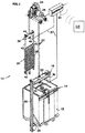
FIG. 1 is an illustration of an embodiment of an elevator system; -
FIG. 2 is an illustration of an embodiment of a load bearing member of an elevator system; -
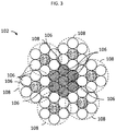
FIG 3 is an illustration of an embodiment of a tension member for a load bearing member of an elevator system; -
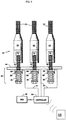
FIG. 4 is an illustration of an embodiment of a termination of a plurality of load bearing members; -
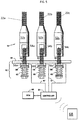
FIG. 5 is another illustration of an embodiment of a termination of a plurality of load bearing members; and -
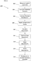
FIG. 6 is a schematic illustration of a method of adjusting tension of a load bearing member. - A detailed description of one or more embodiments of the disclosed apparatus and method are presented herein by way of exemplification and not limitation with reference to the Figures.
- Referring to
FIG. 1 , an embodiment of an elevator system 10 is illustrated. Theelevator system 12 includes acar 14 having acar frame 16 and acab 18, acounterweight 20, a plurality ofload bearing members 22, atraction sheave 24, and amachine 26. Thecar 14 and thecounterweight 20 are connected by the plurality ofload bearing members 22. The plurality ofload bearing members 22 extend over thesheave 24. Rotation of thesheave 24 causes theload bearing members 22 to move, as a result of the traction forces between the sheave andload bearing members 22, and thereby moves thecounterweight 20 andcar 14 through a hoistway (not shown inFIG. 1 ). Themachine 26 provides the rotational force on thesheave 24. - Referring now to
FIG. 2 , in some embodiments, theload bearing member 22 is abelt 100, such as the illustrated coatedsteel belt 100. The belt includes a plurality oftension members 102 disposed in ajacket 104. In some embodiments, as shown inFIG. 3 , eachtension member 102 may be formed from a plurality ofwires 106 twisted into one ormore strands 108 and/or cords, ortension members 102. As seen inFIG. 2 , thebelt 100 has an aspect ratio greater than one (i.e. belt width is greater than belt thickness). Thebelts 100 are constructed to have sufficient flexibility when passing over thesheave 24 to provide low bending stresses, meet belt life requirements and have smooth operation, while being sufficiently strong to be capable of meeting strength requirements for suspending and/or driving theelevator car 14. Thejacket 104 could be any suitable material, including a single material, multiple materials, two or more layers using the same or dissimilar materials, and/or a film. In one arrangement, thejacket 104 could be a polymer, such as an elastomer, applied to thetension members 102 using, for example, an extrusion or a mold wheel process. In another arrangement, thejacket 104 could be a woven fabric that engages and/or integrates thetension members 102. As an additional arrangement, thejacket 104 could be one or more of the previously mentioned alternatives in combination. Further, while steel cord tension carrying members are illustrated inFIG. 2 , one skilled in the art will appreciate that other materials and configurations may be utilized as tension carrying members of thebelt 100. In other embodiments, theload bearing members 22 may be ropes rather thanbelts 100. - Referring again to
FIG. 1 , thecar frame 16 includes aplank 28, a pair ofuprights 30, and across-head 32. Thecab 18 is disposed within thecar frame 16 and is supported by theplank 28. The plurality ofload bearing members 22 are connected to thecross-head 32 through ahitch assembly 34. Thecounterweight 20 includes aframe 36 and a plurality ofweights 38. Theframe 36 includes aplank 40, a pair ofuprights 42, and a cross-head 44. As with thecar frame 16, theload bearing members 22 are connected to the cross-head of thecounterweight 20 through ahitch assembly 46. - The
hitch assembly 34 for thecar frame 16 is shown inFIG. 4 . Although not illustrated in detail, thehitch assembly 46 of thecounterweight 20 is similar to thehitch assembly 34 of thecar frame 16. Thehitch assembly 34 includes ahitch plate 48 having anaperture 50 for each of the plurality ofload bearing members 22. - Each
load bearing member 22 is engaged with atermination 52, a threadedrod 54, aload cell 56, aretainer 58, and aspring 60. The threadedrod 54 provides means to adjust the engagement between thetermination 52 and thehitch assembly 34. Theretainer 58 provides a seat for thespring 60 and mates up against theload cell 56. Thespring 60 provides means to isolate thecar frame 16 from vibrations in theload bearing members 22. - The
load cells 56 form part of a load bearingmember monitoring assembly 62. The monitoringassembly 62 includes the plurality ofload cells 56 on thecar frame 16 and thecounterweight 20, acontroller 64, aremote monitoring system 66, and means 67 to communicate between theload cells 56 and the controller andremote monitoring system 66. Theload cells 56 are sensors that provide an output that corresponds to the sensed level of tension carried by theload bearing member 22 to which theload cell 56 is engaged. In this configuration, compressive forces are applied to theload cells 56 by thesprings 60 andretainers 58. These compressive forces correlate with the tension in theload bearing members 22. This output is then communicated to thecontroller 64 and, if necessary, thecontroller 64 communicates a warning signal to theremote monitoring system 66. In addition to the warning signal, or in the alternative, thecontroller 64 may also communicate the sensed tension levels directly to theremote monitoring system 66. In an alternate embodiment, therope monitoring system 62 does not include a remoteelevator monitoring system 66 and thecontroller 64 stores the warning signal for later review by an on-site elevator mechanic. - Data from the
load cells 56 regardingload bearing member 22 tension is utilized by an elevator mechanic to evaluate and/or adjust tension of theload bearing members 22. Referring toFIG. 5 , eachload bearing member 22a-22c has acorresponding termination 52a-52c, acorresponding load cell 56a-56c, and corresponding threadedrod 54a-54c. While threeload bearing members 22 and corresponding components are illustrated inFIG. 5 , such a configuration is merely exemplary, and elevator systems 10 may utilize other quantities ofload bearing members 22, for example, 2, 4, 5, 6 or moreload bearing members 22. Data from theload cells 56a-56c is communicated to thecontroller 64, which is operably connected to a handheldelectronic device 68, such as a smartphone or tablet, operated by the elevator mechanic. In some embodiments, the connection and communication between thecontroller 64 and the handheldelectronic device 68 is wireless, such as via a wi-fi or Bluetooth connection. In other embodiments, the handheldelectronic device 68 may be configured to communicate directly with theload cells 56a-c, bypassing thecontroller 64. - Referring now to
FIG. 6 , an example of amethod 200 for evaluating and/or adjusting tension of the plurality ofload bearing members 22 is shown. Atstep 202, the load at theload bearing members 22a-c is measured at theload cells 56a-56c. The measured load is equated to a tension of eachload bearing member 22a-c. - At
step 204, the measured tensions of theload bearing members 22a-c are evaluated compared to a predetermined individual tension range. Atstep 206, a tension distribution of the measured tensions are evaluated. For example, in some embodiments, each measured tension is compared to a mean tension of the measured tensions, and in some embodiments the measured tensions are compared to a minimum and maximum measured tension of the measured tensions. Such evaluations may be performed at thecontroller 64, and in other embodiments the evaluations are performed at the handheldelectronic device 68. - At
step 208, the measured tensions and the evaluations may be adjusted, or a compensation factor may be applied based on a position of theelevator car 14 in the hoistway. Atstep 210, an adjustment is calculated for eachload bearing member 22a-c, either at, for example, thecontroller 64 or at the handheldelectronic device 68. In some embodiments, the adjustment is expressed as degrees of turn of a nut 80 connected to the threadedrod 54a-c corresponding to eachload bearing member 22a-c. If calculated at thecontroller 64, the adjustments are communicated to the handheldelectronic device 64 for use by the mechanic atstep 212. Atstep 214, the mechanic makes the appropriate adjustments to the nut 80 as directed. Once the adjustments are made, the tensions are read again atstep 216 to verify that the adjustments are correct and the tension of eachload bearing member 22a-c is within the predetermined individual tension range, and that the distribution of tensions of theload bearing members 22a-c is also within acceptable limits, so that the total load is distributed as desired between theload bearing members 22a-c. - At
step 218, in some embodiments theelevator car 14 is driven to another location in the hoistway and the tensions are measured again viaload cells 56a-c to verify that the measured tensions are within acceptable limits. - Use of device and load cells takes out error and inaccuracies in measurement of spring height and evaluation of tension via spring height. Further, mechanic time in hoistway is reduced and adjustments may be made precisely based on load cell data.
- The term "about" is intended to include the degree of error associated with measurement of the particular quantity based upon the equipment available at the time of filing the application. For example, "about" can include a range of ± 8% or 5%, or 2% of a given value.
- The terminology used herein is for the purpose of describing particular embodiments only and is not intended to be limiting of the present disclosure. As used herein, the singular forms "a", "an" and "the" are intended to include the plural forms as well, unless the context clearly indicates otherwise. It will be further understood that the terms "comprises" and/or "comprising," when used in this specification, specify the presence of stated features, integers, steps, operations, elements, and/or components, but do not preclude the presence or addition of one or more other features, integers, steps, operations, element components, and/or groups thereof.
- While the present disclosure has been described with reference to an exemplary embodiment or embodiments, it will be understood by those skilled in the art that various changes may be made and equivalents may be substituted for elements thereof without departing from the scope of the present disclosure. In addition, many modifications may be made to adapt a particular situation or material to the teachings of the present disclosure without departing from the essential scope thereof. Therefore, it is intended that the present disclosure not be limited to the particular embodiment disclosed as the best mode contemplated for carrying out this present disclosure, but that the present disclosure will include all embodiments falling within the scope of the claims.
Claims (15)
- A method of tension adjustment for a load bearing member of an elevator system, comprising:measuring a load on a load bearing member of an elevator system via a load cell operably connected to the load bearing member, the load cell and the load bearing member connected to an elevator car disposed in a hoistway, the measured load equated with a tension of the load bearing member;comparing the measured tension to a preselected range;determining an adjustment of the tension of the load bearing member;communicating adjustment instructions to a handheld electronic device; and performing the communicated adjustment instructions thereby adjusting the tension of the load bearing member to within the preselected range.
- The method of claim 1, wherein a compensation factor is applied to the measured tension based on location of the elevator car in the hoistway.
- The method of claim 1 or 2, further comprising:moving the elevator car to another location in the hoistway; andremeasuring the load on the load bearing member.
- The method of any of claims 1 to 3, further comprising adjusting the tension on the load bearing member by turning a nut at a connection of the load bearing member to the elevator car.
- The method of any of claims 1 to 4, wherein the elevator system includes a plurality of load bearing members, the method further comprising:measuring a load of each load bearing member of the plurality of load bearing members via a corresponding plurality of load cells operably connected to each load bearing member of the plurality of load bearing members, each measured load equating to a tension of the corresponding load bearing member;evaluating a distribution of the measured tensions of the load bearing members; anddetermining the adjustment of the tension each load bearing member of the plurality of load bearing members based on the evaluation of the distribution of measured tensions.
- The method of claim 5, further comprising adjusting the tension each load bearing member of the plurality of load bearing members to achieve a preselected distribution of the measured tensions.
- The method of claim 5 or 6, wherein the plurality of load bearing members are three or more load bearing members.
- The method of any of claims 5 to 7, further comprising performing a learn run, including:measuring a load on each load bearing member of the plurality of load bearing members at multiple positions in the hoistway;determining a minimum average load variation between the measured loads; andutilizing the minimum average load variation in the determining the adjustment.
- The method of any of claims 1 to 8, wherein the steps of:comparing the measured tension to a preselected range; anddetermining an adjustment of the tension of the load bearing member are performed at the handheld electronic device.
- The method of any of claims 1 to 9, wherein the handheld electronic device is one of a smart phone or a tablet.
- A system for adjusting tension of a plurality of load bearing members of an elevator system, comprising:a plurality of load cells, each load cell operably connected to a load bearing member of the plurality of load bearing members, each load cell configured to measure a load at the load bearing member, the measured load equating to a tension on the corresponding load bearing member;a controller operably connected to the plurality of load cells configured to:evaluate the plurality of measured tensions with respect to one or more preselected ranges; anddetermine an adjustment instruction of each tension of each load bearing member of the plurality of load bearing members; anda handheld electronic operably connected to the controller configured to receive the adjustment instruction of each load bearing members of the plurality of load bearing members.
- The system of claim 11, further comprising a nut operably connected to each load bearing member of the plurality of load bearing members, wherein rotation of the nut adjusts the tension of the associated load bearing member.
- The system of claim 11 or 12, wherein the handheld electronic device is wirelessly connected to the controller.
- The system of any of claims 11 to 13, wherein the handheld electronic device is one of a smart phone or a tablet.
- The system of any of claims 11 to 14, wherein the plurality of load bearing members is three or more load bearing members; and/or wherein the plurality of load bearing members include a plurality of ropes or a plurality of belts.
Applications Claiming Priority (1)
| Application Number | Priority Date | Filing Date | Title |
|---|---|---|---|
| US201762506891P | 2017-05-16 | 2017-05-16 |
Publications (3)
| Publication Number | Publication Date |
|---|---|
| EP3403980A2 true EP3403980A2 (en) | 2018-11-21 |
| EP3403980A3 EP3403980A3 (en) | 2018-12-12 |
| EP3403980B1 EP3403980B1 (en) | 2022-01-26 |
Family
ID=62165483
Family Applications (1)
| Application Number | Title | Priority Date | Filing Date |
|---|---|---|---|
| EP18172166.3A Active EP3403980B1 (en) | 2017-05-16 | 2018-05-14 | Method for tensioning of a load bearing member of an elevator system |
Country Status (5)
| Country | Link |
|---|---|
| US (1) | US11124384B2 (en) |
| EP (1) | EP3403980B1 (en) |
| KR (1) | KR102581247B1 (en) |
| CN (2) | CN108861961A (en) |
| AU (1) | AU2018203458B2 (en) |
Families Citing this family (2)
| Publication number | Priority date | Publication date | Assignee | Title |
|---|---|---|---|---|
| EP3403980B1 (en) * | 2017-05-16 | 2022-01-26 | Otis Elevator Company | Method for tensioning of a load bearing member of an elevator system |
| JP7837223B2 (en) * | 2022-06-02 | 2026-03-30 | 三菱電機ビルソリューションズ株式会社 | Rope length adjustment jig and rope length adjustment method for the main rope used for raising and lowering the elevator car |
Family Cites Families (35)
| Publication number | Priority date | Publication date | Assignee | Title |
|---|---|---|---|---|
| US5149922A (en) * | 1989-09-08 | 1992-09-22 | Mitsubishi Denki Kabushiki Kaisha | Elevator load detector device using movable detector plates |
| JPH07206319A (en) * | 1994-01-13 | 1995-08-08 | Mitsubishi Denki Bill Techno Service Kk | Automatic tension adjusting device for main rope |
| JPH08292111A (en) | 1995-04-24 | 1996-11-05 | Mitsubishi Electric Corp | Belt tension measuring device |
| JP3188833B2 (en) | 1995-11-17 | 2001-07-16 | 三菱電機株式会社 | Elevator rope tension measuring device |
| US6123176A (en) * | 1996-05-28 | 2000-09-26 | Otis Elevator Company | Rope tension monitoring assembly and method |
| US7237656B2 (en) | 2002-02-28 | 2007-07-03 | Otis Elevator Company | Elevator load weighing device |
| JP4820815B2 (en) | 2004-03-16 | 2011-11-24 | オーチス エレベータ カンパニー | Electric signal application method for monitoring the state of an elevator load bearing member |
| EP1730066B1 (en) | 2004-03-16 | 2010-10-20 | Otis Elevator Company | Elevator load bearing member wear and failure detection |
| ES2424019T3 (en) | 2004-03-16 | 2013-09-26 | Otis Elevator Company | Method of measuring the resistance of a tension support |
| ES2360527T3 (en) | 2004-03-16 | 2011-06-06 | Otis Elevator Company | ELECTRICAL CONNECTOR DEVICE FOR USE WITH ELEVATOR LOAD SUPPORT MEMBERS. |
| EP1847501B1 (en) | 2006-04-18 | 2014-10-01 | Inventio AG | Lift installation with a surveillance device of the load carrier for monitoring the status of the load carrier and method for testing the load carrier |
| US8162110B2 (en) * | 2008-06-19 | 2012-04-24 | Thyssenkrupp Elevator Capital Corporation | Rope tension equalizer and load monitor |
| WO2010092618A1 (en) | 2009-02-12 | 2010-08-19 | Otis Elevator Company | Elevator tension member monitoring device |
| ES2541709T3 (en) | 2009-12-21 | 2015-07-23 | Inventio Ag | Surveillance of a suspension and drive means of an elevator installation |
| JP5268978B2 (en) * | 2010-03-19 | 2013-08-21 | 株式会社日立ビルシステム | Elevator main rope tension measuring device |
| WO2011147456A1 (en) * | 2010-05-27 | 2011-12-01 | Kone Corporation | Elevator and elevator rope monitoring device |
| KR101023580B1 (en) * | 2010-07-15 | 2011-03-21 | 전병수 | Elevator Wire Rope Tension Automatic Equalizer |
| WO2012030332A1 (en) | 2010-09-01 | 2012-03-08 | Otis Elevator Company | Resistance-based monitoring system and method |
| BR112013003964A2 (en) * | 2010-09-20 | 2019-09-24 | Otis Elevator Co | "elongated elevator load support member, and method of manufacturing an elongate elevator load support member." |
| DE102011000875A1 (en) * | 2011-02-22 | 2012-08-23 | Siemag Tecberg Gmbh | SME with radio transmission of the measured values |
| US20130056304A1 (en) * | 2011-09-07 | 2013-03-07 | Jose Luis Blanco Sanchez | Elevator Without Counterweight With a Cogged Belt and Pulley |
| CN104583113B (en) * | 2012-08-14 | 2016-08-24 | 三菱电机株式会社 | The counterweight of elevator |
| US9182300B2 (en) | 2012-10-10 | 2015-11-10 | Bosch Automotive Service Solutions Inc. | Method and system for measuring belt tension |
| JP5531169B1 (en) | 2012-10-29 | 2014-06-25 | バンドー化学株式会社 | Belt tension calculation program, belt natural frequency calculation program, and method and apparatus thereof |
| US9278829B2 (en) * | 2012-11-07 | 2016-03-08 | Mitsubishi Electric Research Laboratories, Inc. | Method and system for controlling sway of ropes in elevator systems by modulating tension on the ropes |
| KR20150094605A (en) | 2012-12-10 | 2015-08-19 | 반도 카가쿠 가부시키가이샤 | Natural-oscillation measurement device |
| CN104903692B (en) | 2012-12-12 | 2018-01-12 | 阪东化学株式会社 | Intrinsic frequency measurement apparatus, belt tension computational methods and with calculation method for natural frequencies and computer readable recording medium storing program for performing |
| FI124542B (en) * | 2012-12-30 | 2014-10-15 | Kone Corp | Procedure and arrangement for monitoring the condition of lift lines |
| EP2958844B1 (en) * | 2013-02-21 | 2018-09-05 | Otis Elevator Company | Elevator cord health monitoring |
| WO2015126378A1 (en) * | 2014-02-19 | 2015-08-27 | Otis Elevator Company | Elevator tension member stiffness estimation and monitoring |
| FI126182B (en) * | 2014-06-17 | 2016-07-29 | Kone Corp | Procedure and arrangement for monitoring the condition of a lift line |
| ES1143983Y (en) | 2015-09-01 | 2015-12-16 | Lift Sensor S L | CABLE TENSION CONTROL DEVICE |
| EP3403980B1 (en) * | 2017-05-16 | 2022-01-26 | Otis Elevator Company | Method for tensioning of a load bearing member of an elevator system |
| US10618772B2 (en) * | 2017-06-20 | 2020-04-14 | Otis Elevator Company | Elevator termination assembly that provides an indication of elevator car load |
| US10889470B2 (en) * | 2017-12-08 | 2021-01-12 | Thyssenkrupp Elevator Corporation | Automatic rope tension equalizer system and method |
-
2018
- 2018-05-14 EP EP18172166.3A patent/EP3403980B1/en active Active
- 2018-05-15 KR KR1020180055274A patent/KR102581247B1/en active Active
- 2018-05-15 CN CN201810464713.1A patent/CN108861961A/en active Pending
- 2018-05-15 CN CN202211660671.1A patent/CN115893152A/en active Pending
- 2018-05-16 AU AU2018203458A patent/AU2018203458B2/en active Active
- 2018-05-16 US US15/981,207 patent/US11124384B2/en active Active
Non-Patent Citations (1)
| Title |
|---|
| None |
Also Published As
| Publication number | Publication date |
|---|---|
| AU2018203458A1 (en) | 2018-12-06 |
| KR20180125898A (en) | 2018-11-26 |
| AU2018203458B2 (en) | 2024-05-02 |
| CN115893152A (en) | 2023-04-04 |
| US11124384B2 (en) | 2021-09-21 |
| KR102581247B1 (en) | 2023-09-21 |
| US20180334358A1 (en) | 2018-11-22 |
| CN108861961A (en) | 2018-11-23 |
| EP3403980B1 (en) | 2022-01-26 |
| EP3403980A3 (en) | 2018-12-12 |
Similar Documents
| Publication | Publication Date | Title |
|---|---|---|
| EP3418234B1 (en) | Elevator termination assembly that provides an indication of elevator car load | |
| JP2017061368A (en) | Rope tension measurement apparatus, elevator device and rope tension measurement method of elevator device | |
| AU2018203458B2 (en) | Method for tensioning of a load bearing member of an elevator system | |
| CN102596785B (en) | Method and apparatus for testing tensile stress in a plurality of traction elements of a traction element cord | |
| US10723592B2 (en) | System and method for monitoring an elevator belt | |
| CN102344060A (en) | Elevator | |
| US12351434B2 (en) | Safety system based on hoistway access detection | |
| WO2018100632A1 (en) | Elevator control device and elevator control method | |
| US7673522B2 (en) | Force-reduced measuring method for traction drives, particularly friction pulley drives for elevators | |
| EP3693313B1 (en) | Hoisting rope monitoring device | |
| CN108367884B (en) | Method and device for testing the car structure of an elevator and/or adjusting a load weighing apparatus | |
| KR101691265B1 (en) | Hoisting capacity test and braking force measuring device of an elevator | |
| US20250051131A1 (en) | Device for measuring a force acting on an elevator system, method for measuring a force acting on a movable component of an elevator system, and an elevator system for carrying out the method | |
| JP2008532891A (en) | Device to compensate for lift cable elongation | |
| KR102058189B1 (en) | Elevator safety plank reliability test apparatus | |
| CN117208468B (en) | Tower crane belt length adjusting method | |
| JP5007498B2 (en) | Elevator Weigher Diagnosis Method | |
| JP7806199B1 (en) | Elevator tension adjusting device and tension adjusting method | |
| JP2017061367A (en) | Elevator equipment abnormality detection method | |
| US20250361118A1 (en) | Tension adjustment method for an elevator | |
| DE202024104301U1 (en) | Elevator traction measuring system with variable mass characteristic calculated from acceleration measurements |
Legal Events
| Date | Code | Title | Description |
|---|---|---|---|
| PUAI | Public reference made under article 153(3) epc to a published international application that has entered the european phase |
Free format text: ORIGINAL CODE: 0009012 |
|
| STAA | Information on the status of an ep patent application or granted ep patent |
Free format text: STATUS: THE APPLICATION HAS BEEN PUBLISHED |
|
| PUAL | Search report despatched |
Free format text: ORIGINAL CODE: 0009013 |
|
| AK | Designated contracting states |
Kind code of ref document: A2 Designated state(s): AL AT BE BG CH CY CZ DE DK EE ES FI FR GB GR HR HU IE IS IT LI LT LU LV MC MK MT NL NO PL PT RO RS SE SI SK SM TR |
|
| AX | Request for extension of the european patent |
Extension state: BA ME |
|
| AK | Designated contracting states |
Kind code of ref document: A3 Designated state(s): AL AT BE BG CH CY CZ DE DK EE ES FI FR GB GR HR HU IE IS IT LI LT LU LV MC MK MT NL NO PL PT RO RS SE SI SK SM TR |
|
| AX | Request for extension of the european patent |
Extension state: BA ME |
|
| RIC1 | Information provided on ipc code assigned before grant |
Ipc: B66B 7/10 20060101AFI20181106BHEP |
|
| STAA | Information on the status of an ep patent application or granted ep patent |
Free format text: STATUS: REQUEST FOR EXAMINATION WAS MADE |
|
| 17P | Request for examination filed |
Effective date: 20190611 |
|
| RBV | Designated contracting states (corrected) |
Designated state(s): AL AT BE BG CH CY CZ DE DK EE ES FI FR GB GR HR HU IE IS IT LI LT LU LV MC MK MT NL NO PL PT RO RS SE SI SK SM TR |
|
| STAA | Information on the status of an ep patent application or granted ep patent |
Free format text: STATUS: EXAMINATION IS IN PROGRESS |
|
| 17Q | First examination report despatched |
Effective date: 20201110 |
|
| GRAP | Despatch of communication of intention to grant a patent |
Free format text: ORIGINAL CODE: EPIDOSNIGR1 |
|
| STAA | Information on the status of an ep patent application or granted ep patent |
Free format text: STATUS: GRANT OF PATENT IS INTENDED |
|
| INTG | Intention to grant announced |
Effective date: 20210813 |
|
| GRAS | Grant fee paid |
Free format text: ORIGINAL CODE: EPIDOSNIGR3 |
|
| GRAA | (expected) grant |
Free format text: ORIGINAL CODE: 0009210 |
|
| STAA | Information on the status of an ep patent application or granted ep patent |
Free format text: STATUS: THE PATENT HAS BEEN GRANTED |
|
| AK | Designated contracting states |
Kind code of ref document: B1 Designated state(s): AL AT BE BG CH CY CZ DE DK EE ES FI FR GB GR HR HU IE IS IT LI LT LU LV MC MK MT NL NO PL PT RO RS SE SI SK SM TR |
|
| REG | Reference to a national code |
Ref country code: GB Ref legal event code: FG4D |
|
| REG | Reference to a national code |
Ref country code: CH Ref legal event code: EP |
|
| REG | Reference to a national code |
Ref country code: AT Ref legal event code: REF Ref document number: 1465147 Country of ref document: AT Kind code of ref document: T Effective date: 20220215 |
|
| REG | Reference to a national code |
Ref country code: IE Ref legal event code: FG4D |
|
| REG | Reference to a national code |
Ref country code: DE Ref legal event code: R096 Ref document number: 602018029948 Country of ref document: DE |
|
| REG | Reference to a national code |
Ref country code: LT Ref legal event code: MG9D |
|
| REG | Reference to a national code |
Ref country code: NL Ref legal event code: MP Effective date: 20220126 |
|
| REG | Reference to a national code |
Ref country code: AT Ref legal event code: MK05 Ref document number: 1465147 Country of ref document: AT Kind code of ref document: T Effective date: 20220126 |
|
| PG25 | Lapsed in a contracting state [announced via postgrant information from national office to epo] |
Ref country code: NL Free format text: LAPSE BECAUSE OF FAILURE TO SUBMIT A TRANSLATION OF THE DESCRIPTION OR TO PAY THE FEE WITHIN THE PRESCRIBED TIME-LIMIT Effective date: 20220126 |
|
| PG25 | Lapsed in a contracting state [announced via postgrant information from national office to epo] |
Ref country code: SE Free format text: LAPSE BECAUSE OF FAILURE TO SUBMIT A TRANSLATION OF THE DESCRIPTION OR TO PAY THE FEE WITHIN THE PRESCRIBED TIME-LIMIT Effective date: 20220126 Ref country code: RS Free format text: LAPSE BECAUSE OF FAILURE TO SUBMIT A TRANSLATION OF THE DESCRIPTION OR TO PAY THE FEE WITHIN THE PRESCRIBED TIME-LIMIT Effective date: 20220126 Ref country code: PT Free format text: LAPSE BECAUSE OF FAILURE TO SUBMIT A TRANSLATION OF THE DESCRIPTION OR TO PAY THE FEE WITHIN THE PRESCRIBED TIME-LIMIT Effective date: 20220526 Ref country code: NO Free format text: LAPSE BECAUSE OF FAILURE TO SUBMIT A TRANSLATION OF THE DESCRIPTION OR TO PAY THE FEE WITHIN THE PRESCRIBED TIME-LIMIT Effective date: 20220426 Ref country code: LT Free format text: LAPSE BECAUSE OF FAILURE TO SUBMIT A TRANSLATION OF THE DESCRIPTION OR TO PAY THE FEE WITHIN THE PRESCRIBED TIME-LIMIT Effective date: 20220126 Ref country code: HR Free format text: LAPSE BECAUSE OF FAILURE TO SUBMIT A TRANSLATION OF THE DESCRIPTION OR TO PAY THE FEE WITHIN THE PRESCRIBED TIME-LIMIT Effective date: 20220126 Ref country code: ES Free format text: LAPSE BECAUSE OF FAILURE TO SUBMIT A TRANSLATION OF THE DESCRIPTION OR TO PAY THE FEE WITHIN THE PRESCRIBED TIME-LIMIT Effective date: 20220126 Ref country code: BG Free format text: LAPSE BECAUSE OF FAILURE TO SUBMIT A TRANSLATION OF THE DESCRIPTION OR TO PAY THE FEE WITHIN THE PRESCRIBED TIME-LIMIT Effective date: 20220426 |
|
| PG25 | Lapsed in a contracting state [announced via postgrant information from national office to epo] |
Ref country code: PL Free format text: LAPSE BECAUSE OF FAILURE TO SUBMIT A TRANSLATION OF THE DESCRIPTION OR TO PAY THE FEE WITHIN THE PRESCRIBED TIME-LIMIT Effective date: 20220126 Ref country code: LV Free format text: LAPSE BECAUSE OF FAILURE TO SUBMIT A TRANSLATION OF THE DESCRIPTION OR TO PAY THE FEE WITHIN THE PRESCRIBED TIME-LIMIT Effective date: 20220126 Ref country code: GR Free format text: LAPSE BECAUSE OF FAILURE TO SUBMIT A TRANSLATION OF THE DESCRIPTION OR TO PAY THE FEE WITHIN THE PRESCRIBED TIME-LIMIT Effective date: 20220427 Ref country code: FI Free format text: LAPSE BECAUSE OF FAILURE TO SUBMIT A TRANSLATION OF THE DESCRIPTION OR TO PAY THE FEE WITHIN THE PRESCRIBED TIME-LIMIT Effective date: 20220126 Ref country code: AT Free format text: LAPSE BECAUSE OF FAILURE TO SUBMIT A TRANSLATION OF THE DESCRIPTION OR TO PAY THE FEE WITHIN THE PRESCRIBED TIME-LIMIT Effective date: 20220126 |
|
| PG25 | Lapsed in a contracting state [announced via postgrant information from national office to epo] |
Ref country code: IS Free format text: LAPSE BECAUSE OF FAILURE TO SUBMIT A TRANSLATION OF THE DESCRIPTION OR TO PAY THE FEE WITHIN THE PRESCRIBED TIME-LIMIT Effective date: 20220526 |
|
| REG | Reference to a national code |
Ref country code: DE Ref legal event code: R097 Ref document number: 602018029948 Country of ref document: DE |
|
| PG25 | Lapsed in a contracting state [announced via postgrant information from national office to epo] |
Ref country code: SM Free format text: LAPSE BECAUSE OF FAILURE TO SUBMIT A TRANSLATION OF THE DESCRIPTION OR TO PAY THE FEE WITHIN THE PRESCRIBED TIME-LIMIT Effective date: 20220126 Ref country code: SK Free format text: LAPSE BECAUSE OF FAILURE TO SUBMIT A TRANSLATION OF THE DESCRIPTION OR TO PAY THE FEE WITHIN THE PRESCRIBED TIME-LIMIT Effective date: 20220126 Ref country code: RO Free format text: LAPSE BECAUSE OF FAILURE TO SUBMIT A TRANSLATION OF THE DESCRIPTION OR TO PAY THE FEE WITHIN THE PRESCRIBED TIME-LIMIT Effective date: 20220126 Ref country code: EE Free format text: LAPSE BECAUSE OF FAILURE TO SUBMIT A TRANSLATION OF THE DESCRIPTION OR TO PAY THE FEE WITHIN THE PRESCRIBED TIME-LIMIT Effective date: 20220126 Ref country code: DK Free format text: LAPSE BECAUSE OF FAILURE TO SUBMIT A TRANSLATION OF THE DESCRIPTION OR TO PAY THE FEE WITHIN THE PRESCRIBED TIME-LIMIT Effective date: 20220126 Ref country code: CZ Free format text: LAPSE BECAUSE OF FAILURE TO SUBMIT A TRANSLATION OF THE DESCRIPTION OR TO PAY THE FEE WITHIN THE PRESCRIBED TIME-LIMIT Effective date: 20220126 |
|
| PG25 | Lapsed in a contracting state [announced via postgrant information from national office to epo] |
Ref country code: AL Free format text: LAPSE BECAUSE OF FAILURE TO SUBMIT A TRANSLATION OF THE DESCRIPTION OR TO PAY THE FEE WITHIN THE PRESCRIBED TIME-LIMIT Effective date: 20220126 |
|
| PLBE | No opposition filed within time limit |
Free format text: ORIGINAL CODE: 0009261 |
|
| STAA | Information on the status of an ep patent application or granted ep patent |
Free format text: STATUS: NO OPPOSITION FILED WITHIN TIME LIMIT |
|
| REG | Reference to a national code |
Ref country code: CH Ref legal event code: PL |
|
| 26N | No opposition filed |
Effective date: 20221027 |
|
| REG | Reference to a national code |
Ref country code: BE Ref legal event code: MM Effective date: 20220531 |
|
| GBPC | Gb: european patent ceased through non-payment of renewal fee |
Effective date: 20220514 |
|
| PG25 | Lapsed in a contracting state [announced via postgrant information from national office to epo] |
Ref country code: MC Free format text: LAPSE BECAUSE OF FAILURE TO SUBMIT A TRANSLATION OF THE DESCRIPTION OR TO PAY THE FEE WITHIN THE PRESCRIBED TIME-LIMIT Effective date: 20220126 Ref country code: LU Free format text: LAPSE BECAUSE OF NON-PAYMENT OF DUE FEES Effective date: 20220514 Ref country code: LI Free format text: LAPSE BECAUSE OF NON-PAYMENT OF DUE FEES Effective date: 20220531 Ref country code: CH Free format text: LAPSE BECAUSE OF NON-PAYMENT OF DUE FEES Effective date: 20220531 |
|
| PG25 | Lapsed in a contracting state [announced via postgrant information from national office to epo] |
Ref country code: SI Free format text: LAPSE BECAUSE OF FAILURE TO SUBMIT A TRANSLATION OF THE DESCRIPTION OR TO PAY THE FEE WITHIN THE PRESCRIBED TIME-LIMIT Effective date: 20220126 |
|
| PG25 | Lapsed in a contracting state [announced via postgrant information from national office to epo] |
Ref country code: IE Free format text: LAPSE BECAUSE OF NON-PAYMENT OF DUE FEES Effective date: 20220514 |
|
| PG25 | Lapsed in a contracting state [announced via postgrant information from national office to epo] |
Ref country code: GB Free format text: LAPSE BECAUSE OF NON-PAYMENT OF DUE FEES Effective date: 20220514 Ref country code: BE Free format text: LAPSE BECAUSE OF NON-PAYMENT OF DUE FEES Effective date: 20220531 |
|
| PG25 | Lapsed in a contracting state [announced via postgrant information from national office to epo] |
Ref country code: IT Free format text: LAPSE BECAUSE OF FAILURE TO SUBMIT A TRANSLATION OF THE DESCRIPTION OR TO PAY THE FEE WITHIN THE PRESCRIBED TIME-LIMIT Effective date: 20220126 |
|
| PG25 | Lapsed in a contracting state [announced via postgrant information from national office to epo] |
Ref country code: HU Free format text: LAPSE BECAUSE OF FAILURE TO SUBMIT A TRANSLATION OF THE DESCRIPTION OR TO PAY THE FEE WITHIN THE PRESCRIBED TIME-LIMIT; INVALID AB INITIO Effective date: 20180514 |
|
| PG25 | Lapsed in a contracting state [announced via postgrant information from national office to epo] |
Ref country code: MK Free format text: LAPSE BECAUSE OF FAILURE TO SUBMIT A TRANSLATION OF THE DESCRIPTION OR TO PAY THE FEE WITHIN THE PRESCRIBED TIME-LIMIT Effective date: 20220126 Ref country code: CY Free format text: LAPSE BECAUSE OF FAILURE TO SUBMIT A TRANSLATION OF THE DESCRIPTION OR TO PAY THE FEE WITHIN THE PRESCRIBED TIME-LIMIT Effective date: 20220126 |
|
| PG25 | Lapsed in a contracting state [announced via postgrant information from national office to epo] |
Ref country code: MT Free format text: LAPSE BECAUSE OF FAILURE TO SUBMIT A TRANSLATION OF THE DESCRIPTION OR TO PAY THE FEE WITHIN THE PRESCRIBED TIME-LIMIT Effective date: 20220126 |
|
| PGFP | Annual fee paid to national office [announced via postgrant information from national office to epo] |
Ref country code: DE Payment date: 20250423 Year of fee payment: 8 |
|
| PGFP | Annual fee paid to national office [announced via postgrant information from national office to epo] |
Ref country code: FR Payment date: 20250423 Year of fee payment: 8 |
|
| PG25 | Lapsed in a contracting state [announced via postgrant information from national office to epo] |
Ref country code: TR Free format text: LAPSE BECAUSE OF FAILURE TO SUBMIT A TRANSLATION OF THE DESCRIPTION OR TO PAY THE FEE WITHIN THE PRESCRIBED TIME-LIMIT Effective date: 20220126 |