EP3403960A1 - Yarn processing apparatus and roller cover - Google Patents
Yarn processing apparatus and roller cover Download PDFInfo
- Publication number
- EP3403960A1 EP3403960A1 EP18171191.2A EP18171191A EP3403960A1 EP 3403960 A1 EP3403960 A1 EP 3403960A1 EP 18171191 A EP18171191 A EP 18171191A EP 3403960 A1 EP3403960 A1 EP 3403960A1
- Authority
- EP
- European Patent Office
- Prior art keywords
- yarn
- roller
- conveyance roller
- guide roller
- yarns
- Prior art date
- Legal status (The legal status is an assumption and is not a legal conclusion. Google has not performed a legal analysis and makes no representation as to the accuracy of the status listed.)
- Granted
Links
Images





Classifications
-
- B—PERFORMING OPERATIONS; TRANSPORTING
- B65—CONVEYING; PACKING; STORING; HANDLING THIN OR FILAMENTARY MATERIAL
- B65H—HANDLING THIN OR FILAMENTARY MATERIAL, e.g. SHEETS, WEBS, CABLES
- B65H51/00—Forwarding filamentary material
- B65H51/02—Rotary devices, e.g. with helical forwarding surfaces
- B65H51/04—Rollers, pulleys, capstans, or intermeshing rotary elements
-
- D—TEXTILES; PAPER
- D01—NATURAL OR MAN-MADE THREADS OR FIBRES; SPINNING
- D01D—MECHANICAL METHODS OR APPARATUS IN THE MANUFACTURE OF ARTIFICIAL FILAMENTS, THREADS, FIBRES, BRISTLES OR RIBBONS
- D01D11/00—Other features of manufacture
-
- B—PERFORMING OPERATIONS; TRANSPORTING
- B65—CONVEYING; PACKING; STORING; HANDLING THIN OR FILAMENTARY MATERIAL
- B65H—HANDLING THIN OR FILAMENTARY MATERIAL, e.g. SHEETS, WEBS, CABLES
- B65H2701/00—Handled material; Storage means
- B65H2701/30—Handled filamentary material
- B65H2701/31—Textiles threads or artificial strands of filaments
Definitions
- the present invention relates to a yarn processing apparatus and a roller cover.
- a spun yarn drawing apparatus recited in Patent Literature 1 Japanese Unexamined Patent Publication No. 2016-164314 is configured to draw, by godet rollers, a yarn Y spun out from a spinning apparatus and convey the drawn yarn to a winding unit by a guide roller. Then the spun yarn drawing apparatus forms a package by winding the drawn yarn onto a bobbin at the winding unit.
- Patent Literature 1 when the yarn is conveyed by the guide roller, the rotating guide roller stirs circumambient air.
- the energy consumed for the stirring of the circumambient air by the guide roller hereinafter, this may be referred to as "power consumption”
- the power consumption of a motor which rotationally drives the guide roller is disadvantageously large.
- An object of the present invention is to provide a yarn processing apparatus and a roller cover, which make it possible to effectively reduce power consumption when a yarn is conveyed by a yarn conveyance roller.
- a yarn processing apparatus of the first aspect of the invention includes: a yarn conveyance roller conveying yarns: and a roller cover covering the yarn conveyance roller, the roller cover including: a first part which is provided to surround the outer circumferential surface of the yarn conveyance roller, a yarn inlet through which yarns are introduced from outside into a space in which the yarn conveyance roller is provided and a yarn outlet through which the yarns in the space are taken out being formed in the first part; and a second part which faces a leading end surface of the yarn conveyance roller in a direction along an axis of the yarn conveyance roller and is connected to the first part, the distance from the central axis of the yarn conveyance roller to an inner wall surface of the first part being 1.6 times or more as long as and 1.9 times or less as long as the radius of the yarn conveyance roller, at every part of the inner wall surface.
- the roller cover is provided to cover the yarn conveyance roller, an amount of air surrounding the yarn conveyance roller is reduced, and hence the power consumption is reduced.
- the distance from the central axis of the roller cover to the inner wall surface of the first part is arranged to be 1.6 times or more as long as and 1.9 times or less as long as the radius of the yarn conveyance roller, at every part of the inner wall surface.
- a yarn processing apparatus of the second aspect of the invention includes: a yarn conveyance roller conveying yarns: and a roller cover covering the yarn conveyance roller, the roller cover including: a first part which is provided to surround the outer circumferential surface of the yarn conveyance roller, a yarn inlet through which yarns are introduced from outside into a space in which the yarn conveyance roller is provided and a yarn outlet through which the yarns in the space are taken out being formed in the first part; and a second part which faces a leading end surface of the yarn conveyance roller in a direction along an axis of the yarn conveyance roller and is connected to the first part, a difference between the distance from the central axis of the yarn conveyance roller to an inner wall surface of the first part and the radius of the yarn conveyance roller being equal to or longer than 40mm and equal to or shorter than 55mm, at every part of the inner wall surface.
- the roller cover is provided to cover the yarn conveyance roller, an amount of air surrounding the yarn conveyance roller is reduced, and hence the power consumption is reduced.
- the distance between the outer circumferential surface of the yarn conveyance roller and the inner wall surface of the first part is too short, an airflow in the gap between the outer circumferential surface of the yarn conveyance roller and the inner wall surface of the first part tends to be disturbed, with the result that the power consumption is disadvantageously increased.
- the difference between the distance from the central axis of the yarn conveyance roller to the inner wall surface of the first part and the radius of the yarn conveyance roller is arranged to be equal to or longer than 40mm and equal to or shorter than 55mm, at every part of the inner wall surface.
- the yarn processing apparatus of the first or second aspect is arranged such that, the inner wall surface of the roller cover is circular in shape and centered at the axis of the yarn conveyance roller, when viewed in the direction along the axis of the yarn conveyance roller.
- the inner wall surface of the first part of the roller cover is circular in shape and centered at the axis of the yarn conveyance roller when viewed in the axial direction of the yarn conveyance roller.
- the yarn processing apparatus of any one of the first to third aspects is arranged such that the running speed of the outer circumferential surface of the yarn conveyance roller is equal to or higher than 1000m/min and equal to or lower than 6000m/min.
- the roller cover with the above-described size is provided for the yarn conveyance roller when the running speed of the outer circumferential surface of the yarn conveyance roller is equal to or higher than 1000m/min and equal to or lower than 6000m/min. With this arrangement, the power consumption is effectively reduced.
- a roller cover of the fifth aspect of the invention covering a yarn conveyance roller by which yarns are conveyed, includes: a first part which is provided to surround the outer circumferential surface of the yarn conveyance roller, a yarn inlet through which yarns are introduced from outside into a space in which the yarn conveyance roller is provided and a yarn outlet through which the yarns in the space are taken out being formed in the first part; and a second part which faces a leading end surface of the yarn conveyance roller in a direction along an axis of the yarn conveyance roller and is connected to the first part, the distance from the central axis of the yarn conveyance roller to an inner wall surface of the first part being 1.6 times or more as long as and 1.9 times or less as long as the radius of the yarn conveyance roller, at every part of the inner wall surface.
- a roller cover of the sixth aspect of the invention covering a yarn conveyance roller by which yarns are conveyed, includes: a first part which is provided to surround the outer circumferential surface of the yarn conveyance roller, a yarn inlet through which yarns are introduced from outside into a space in which the yarn conveyance roller is provided and a yarn outlet through which the yarns in the space are taken out being formed in the first part; and a second part which faces a leading end surface of the yarn conveyance roller in a direction along an axis of the yarn conveyance roller and is connected to the first part, a difference between the distance from the central axis of the yarn conveyance roller to an inner wall surface of the first part and the radius of the yarn conveyance roller being equal to or longer than 40mm and equal to or shorter than 55mm, at every part of the inner wall surface.
- the distance from the center of the yarn conveyance roller is 1.6 times or more as long as and 1.9 times or less as long as the radius of the yarn conveyance roller at every part, or when the difference between the distance from the central axis of the yarn conveyance roller to the inner wall surface of the first part of the roller cover and the radius of the yarn conveyance roller is equal to or longer than 40mm and equal to or shorter than 55mm at every part of the inner wall surface, power consumption is effectively reduced.
- the spun yarn take-up apparatus 1 includes a spun yarn drawing apparatus 3 and a yarn winding apparatus 4.
- a spinning apparatus 2 is provided above the spun yarn take-up apparatus 1.
- a molten fibrous material such as polyester, which is continuously spun out from a spinneret of the spinning apparatus 2, is solidified by cooling air blown onto the material at a cooling cylinder 5, with the result that yarns Y are formed.
- the spun yarn drawing apparatus 3 is provided below the cooling cylinder 5 to draw the yarns Y coming down from the cooling cylinder 5.
- the yarn winding apparatus 4 is configured to form wound packages 9 by winding the yarns Y drawn by the spun yarn drawing apparatus 3 onto bobbins 29.
- left-right direction which is orthogonal to an up-down direction
- left-right direction a direction which is orthogonal to the up-down direction, the left-right direction, and the sheet of FIG. 1
- front-rear direction a direction orthogonal to the sheet of FIG. 1 and toward the viewer of FIG. 1
- forward a direction orthogonal to the sheet of FIG. 1 and away from the viewer of FIG. 1
- rearward a direction orthogonal to the sheet of FIG. 1 and away from the viewer of FIG. 1
- the spun yarn drawing apparatus 3 includes an oil guide 6 and a heating-drawing unit 7.
- the oil guide 6 is configured to apply oil to each of the yarns Y spun out from the spinning apparatus 2.
- the yarns Y to which oil has been applied by the oil guide 6 are sent to the heating-drawing unit 7 via a guide roller 17.
- the heating-drawing unit 7 includes a thermal insulation box 16 and five godet rollers 11a to 11e housed in the thermal insulation box 16.
- the thermal insulation box 16 is a box made of a heat insulating material.
- a yarn inlet 16a through which the yarns Y are introduced into the thermal insulation box 16 and a yarn outlet 16b through which the yarns Y go outside from the thermal insulation box 16 are formed.
- the yarn inlet 16a is formed at a lower end portion of the side wall member of the thermal insulation box 16, whereas the yarn outlet 16b is formed at an upper end portion of the side wall member of the thermal insulation box 16.
- the godet rollers 11a to 11e are rollers which are long in the front-rear direction. Among the five godet rollers 11a to 11e, the godet roller 11a is provided in the vicinity of a bottom portion of the thermal insulation box 16. Above this godet roller 11a, the remaining four godet rollers 11b to 11e are arranged to form left and right columns which are staggered.
- the yarns Y introduced into the thermal insulation box 16 through the yarn inlet 16a are wound onto the five godet rollers 11a to 11e in order. The yarns Y are wound onto the lowest godet roller 11, then onto the second lowest godet roller 11, and so on.
- the yarns Y are wound onto each of the five godet rollers 11a to 11e at a wining angle of less than 270 degrees. On each of the godet rollers 11a to 11e, the yarns Y are not wound more than once. As the yarns Y are conveyed in order by the five godet rollers 11a to 11e, the yarns Y run from the yarn inlet 16a to the yarn outlet 16b along a meandering and non-crossing yarn path which is on a plane which is in parallel to the sheet of FIG. 1 .
- Each of the five godet rollers 11a to 11e is rotationally driven by an unillustrated motor.
- Each of the five godet rollers 11a to 11e is a yarn heating roller including a heater therein.
- the lower three godet rollers 11a to 11c on the upstream in the yarn running direction are yarn heating rollers for preliminarily heating the yarns Y to a drawable temperature.
- the glass transition temperature of the yarns Y is about 80 degrees centigrade, and hence the heating temperatures (roller surface temperatures) of the three godet rollers 11a to 11c are set at temperatures (e.g., 80 to 95 degrees centigrade) slightly higher than the glass transition temperature.
- the upper two godet rollers 11d and 11e on the downstream in the yarn running direction are yarn heating rollers for thermally setting the drawn yarns Y.
- the heating temperatures (roller surface temperatures) of the two godet rollers 11d and 11e are set at temperatures (e.g., 120 to 150 degrees centigrade) higher than the heating temperatures of the lower three godet rollers 11a to 11c.
- the yarn feeding speeds of the upper two godet rollers 11d and 11e are higher than those of the lower three godet rollers 11a to 11c.
- the yarns Y introduced into the thermal insulation box 16 are, to begin with, preliminarily heated to the drawable temperature, i.e., the glass transition temperature while the yarns Y are conveyed by the lower three godet rollers 11a to 11c.
- the yarns Y having been preliminarily heated to the glass transition temperature are then drawn on account of a yarn feeding speed difference between the two godet rollers 11c and 11d.
- the yarns Y are heated to a higher temperature while being conveyed by the upper two godet rollers 11d and 11e, with the result that the drawn yarns Y are thermally set.
- the yarns Y which have been drawn in this way go outside from the thermal insulation box 16 through the yarn outlet 16b, and are then sent to the yarn winding apparatus 4 by the guide roller 18.
- the guide roller 18 and a later-described roller cover 40 covering the guide roller 18 will be detailed later.
- the yarn winding apparatus 4 is provided below the spun yarn drawing apparatus 3.
- the yarn winding apparatus 4 includes a bobbin holder 27 and a contact roller 28.
- the bobbin holder 27 is long in the front-rear direction, is column-shaped, and is rotationally driven by an unillustrated motor.
- bobbins 29 are attached to be lined up along the axis of the bobbin holder 27.
- the yarn winding apparatus 4 is configured to form wound packages 9 by simultaneously winding the yarns Y onto the bobbins 29 by rotating the bobbin holder 27.
- the contact roller 28 is a roller which is long in the front-rear direction. The contact roller 28 adjusts the shape of each of the wound packages 9 in such a way that the contact roller 28 makes contact with the surface of each of the wound packages 9 and applies a predetermined contact pressure thereto.
- the guide roller 18 is, for example, a roller which is long in the front-rear direction and is about 110mm in outer diameter Dr.
- the guide roller 18 is substantially identical in height with the yarn outlet 16b of the thermal insulation box 16.
- the yarns Y sent from the thermal insulation box 16 are wound.
- the yarns Y are wound onto the guide roller 18 at a winding angle ⁇ of, for example, 90 degrees.
- the guide roller 18 forwards the yarns Y from the thermal insulation box 16 toward the yarn winding apparatus 4 which is provided below the guide roller 18.
- a flange portion 31 is provided at a base end portion of the guide roller 18.
- the outer diameter Df (e.g., about 160mm) of the flange portion 31 is longer than the outer diameter Dr of the guide roller 18.
- a motor 32 is attached to the flange portion 31.
- the guide roller 18 is rotationally driven by the motor 32.
- the motor 32 rotationally drives the guide roller 18 at a rotation speed with which the running speed of the outer circumferential surface 18a of the guide roller 18 is not lower than 1000m/min and not higher than 6000m/min.
- the guide roller 18 is covered with the roller cover 40.
- the roller cover 40 is made of, for example, a synthetic resin material and a metal material, and is attached to a frame 51 of the spun yarn take-up apparatus 1 to which the guide roller 18 is attached.
- the roller cover 40 includes a first part 41, a second part 42, and a third part 43.
- the first part 41 is formed to be cylindrical in shape (i.e., an inner wall surface 41a is circular in shape when viewed in the direction along the axis of the guide roller 18), and is provided to surround the outer circumferential surface 18a of the guide roller 18.
- the first part 41 and the guide roller 18 are coaxial and share the same axis J as the central axis.
- the inner diameter Dc of the first part 41 is 1.6 times or more as long as and 1.9 times or less as long as the outer diameter Dr of the guide roller 18.
- the inner diameter Dc of the first part 41 is equal to or longer than 190mm and equal to or shorter than 220mm.
- a gap 46 is formed between the outer circumferential surface 18a of the guide roller 18 and the inner wall surface 41a of the first part 41 so that the distance C between the outer circumferential surface 18a and the inner wall surface 41a is equal to or longer than 40mm and equal to or shorter than 55mm.
- the distance C is constant at every part of the gap 46.
- the first part 41 extends along the entire length of the guide roller 18 in the axial direction of the guide roller 18, and the front end of the first part 41 is positioned forward of the leading end of the guide roller 18.
- a yarn inlet 44 is formed to be substantially identical in height with the upper end of the guide roller 18.
- a yarn outlet 45 is formed to be substantially identical in position with the right end of the guide roller 18 in the left-right direction.
- the yarns Y conveyed by the guide roller 18 go outside from the roller cover 40 through the yarn outlet 45, and are then sent to the yarn winding apparatus 4.
- Each of the yarn inlet 44 and the yarn outlet 45 is long in the axial direction of the guide roller 18.
- the length Ls of each of these inlet 44 and outlet 45 is about 134mm in the axial direction of the guide roller 18, and the width Ws thereof is about 10mm.
- the second part 42 faces a leading end surface 18b of the guide roller 18.
- the second part 42 is circular in shape and is substantially identical in diameter with the first part 41 when viewed in the axial direction of the guide roller 18.
- the second part 42 is connected to a front end portion of the first part 41.
- the third part 43 is provided at a rear end portion of the first part 41.
- the third part 43 juts outward from the first part 41 in the radial direction of the guide roller 18, and is substantially rectangular in shape when viewed in the axial direction of the guide roller 18.
- the third part 43 is fixed to the frame 51 by an unillustrated bolt or the like.
- the guide roller 18 is provided in a space surrounded by the frame 51 and the roller cover 40 (the first part 41 and the second part 42). This space communicates with the outside only at the yarn inlet 44 and the yarn outlet 45.
- the guide roller 18 stirs circumambient air.
- the power consumption of the motor 32 is disadvantageously large.
- the guide roller 18 because the guide roller 18 is covered with the roller cover 40, an amount of air surrounding the outer circumferential surface 18a of the guide roller 18 is reduced, and hence the power consumption is reduced.
- the yarn inlet 44 for introducing the yarns Y and the yarn outlet 45 for taking the yarns Y out are formed at the first part 41.
- an airflow (accompanied flow) generated around the running yarns Y flows into the space in the roller cover 40 through the yarn inlet 44, together with the yarns Y.
- an airflow (accompanied flow) generated around the running yarns Y flows out from the roller cover 40 through the yarn outlet 45, together with the yarns Y.
- the inner diameter Dc of the first part 41 is arranged to be 1.6 times or more as long as and 1.9 times or less as long as the outer diameter Dr of the guide roller 18, as described above, and hence the gap 46 which is equal to or longer than 40mm and equal to or shorter than 55mm is formed between the outer circumferential surface 18a of the guide roller 18 and the inner wall surface 41a of the first part 41.
- the first part 41 is formed to be cylindrical in shape and the first part 41 and the guide roller 18 share the same central axis, the distance between the outer circumferential surface 18a of the guide roller 18 and the inner wall surface 41a of the first part 41 is constant, and hence stabilization of the airflow in the gap 46 is facilitated. This makes it possible to effectively reduce the power consumption.
- the running speed of the outer circumferential surface 18a of the guide roller 18 is high, i.e., is about 1000m/min or higher and 6000m/min or lower.
- the power consumption is therefore high without the roller cover 40.
- the roller cover 40 is sized as described above. The power consumption is therefore effectively reduced as the analysis results and experimentation results described below indicate.
- Example 1 to 3 and Comparative Examples 1 and 2 the power consumption was calculated by using an analytical model shown in FIG. 4 and FIG. 5 , corresponding to a guide roller 18 and a roller cover 40 identical with those in the embodiment above.
- Comparative Examples 3 to 5 the power consumption was calculated by using an analytical model shown in FIG. 6 .
- the outer diameter Dr of the guide roller 18 was 110mm and the outer diameter Df of the flange portion 31 was 160mm.
- the entire length Lr in the axial direction of the guide roller 18 inclusive of the flange portion 31 was 217.5mm
- the length Lc of the space formed by the roller cover 40 and the frame 51 was 237.5mm in the axial direction of the guide roller 18, and the distance K1 between the leading end surface 18b of the guide roller 18 and the second part 42 of the roller cover 40 was 10mm.
- the height H of the frame 51 was 240mm.
- the thickness Tc of the roller cover 40 was 10mm.
- the length Ls was 134mm in the axial direction of the guide roller 18 and the width Ws thereof was 10mm.
- the inner diameter Dc of the first part 41 was constant.
- the inner diameters Dc were 220mm, 200mm, and 190mm, respectively.
- the inner diameters Dc were 280mm and 240mm, respectively.
- the first part 41 was arranged such that the inner diameter Db of a part surrounding the flange portion 31 of the guide roller 18 was 180mm whereas the inner diameter Dc of a part surrounding a portion which was on the leading end side as compared to the flange portion 31 was shorter than the inner diameter Db.
- the inner diameters Dc were 160mm, 140mm, and 120mm, respectively.
- the distance K3 between the leading end of the flange portion 31 and the leading end of the inner wall surface of the part surrounding the flange portion 31 was 10mm.
- the lengths in the analytical model of FIG. 6 other than the above were identical with those in the analytical model of FIG.
- the running speed of the outer circumferential surface 18a of the guide roller 18 was 5000m/min. Furthermore, as shown in FIG. 4 to FIG. 6 , analysis was performed with the assumption that a band body B having the width Lb of 124mm and the thickness Tb of 0.088mm ran.
- the distance K4 between an end of the band body B on the leading end side of the guide roller 18 and the leading end of the guide roller 18 was 30mm.
- the winding angle of the band body B onto the guide roller 18 was 90 degrees.
- a circle which was centered at the central axis (axis J) of the guide roller 18 and had a diameter De (500mm) was set as an exit boundary Ek in the radial direction of the guide roller 18.
- a line, which was on the side opposite to the frame 51 over the center in the axial direction of the guide roller 18 inclusive of the flange portion 31 and was away from the center in the axial direction of the guide roller 18 inclusive of the flange portion 31 by Le1 (150mm) was set as a front exit boundary Ej1 in the axial direction of the guide roller 18.
- a line which was on the same side as the frame 51 with respect to the center in the axial direction of the guide roller 18 inclusive of the flange portion 31 and was away from the center in the axial direction of the guide roller 18 inclusive of the flange portion 31 by Le2 (150mm), was set as a front exit boundary Ej2 in the axial direction of the guide roller 18.
- a k- ⁇ turbulence model was applied to each of governing equations (1) and (2) below, discretization was done by a finite volume method, and approximate solutions were calculated by an iteration method.
- the equation (1) indicates that the fluid is incompressible fluid.
- the equation (2) is a RANS equation.
- the front-rear direction was an x direction
- the left-right direction was a y direction
- the up-down direction was a z direction.
- ⁇ indicates an angular speed of the guide roller 18.
- the torque M was calculated by using a pressure P obtained by numerical calculation by the equations (1) and (2) and by using equations (3), (4), and (5) below.
- the pressure P obtained by numerical calculation by the equations (1) and (2) corresponds to Pf in the equation (4).
- FIG. 7(a) and FIG. 7(b) show the analysis results of Examples 1 to 3 and Comparative Examples 1 to 6. As shown in FIG. 7(a) and FIG. 7(b), as a result of comparison between (i) Comparative Example 6 and (ii) Examples 1 to 3 and Comparative Examples 1 to 5, it is found that the power consumption is reduced when the roller cover 40 covering the guide roller 18 is provided, as compared to cases where the roller cover 40 is not provided.
- Example 4 by using an apparatus shown in FIG. 8(a) , the power consumption of the motor 32 rotationally driving the guide roller 18 covered with the roller cover 40 as in the embodiment above was measured.
- an AC voltage supplied from an AC power source 101 was transformed by a transformer 102, the voltage was converted to a DC voltage by an inverter 103, and the motor 32 was rotationally driven by the DC voltage output to the motor 32.
- a power meter 104 was connected between the inverter 103 and the motor 32 and the power consumption of the motor 32 was measured by the power meter 104.
- Example 4 the outer diameter Dr of the guide roller 18 was 110mm, the outer diameter Df of the flange portion 31 was 160mm, and the inner diameter Dc of the first part 41 was 190mm. Furthermore, the entire length Lr in the axial direction of the guide roller 18 inclusive of the flange portion 31 was 218mm, and the length Lc of the space formed by the roller cover 40 and the frame 51 was 248mm in the axial direction of the guide roller 18. The height of the frame 51 was 240mm. The thickness Tc of the roller cover 40 was 10mm. Furthermore, in each of the yarn inlet 44 and the yarn outlet 45, the length Ls was 134mm in the axial direction of the guide roller 18 and the width Ws thereof was 10mm.
- the power consumption of the motor 32 was measured in Comparative Example 7 on the same conditions as in Example 4 except that the roller cover 40 was detached.
- FIG. 8(b) shows the experimentation results of Example 4 and Comparative Example 7.
- the "measured power” in FIG. 8(b) indicates the power consumption of the motor 32 measured by the power meter 104 in FIG. 8(a) .
- the power consumption in FIG. 8(b) was calculated by subtracting, from the power consumption measured by the power meter 104, energy ( ⁇ 79W) equivalent to a loss by the motor 32 and energy ( ⁇ 110W) equivalent to a loss by the tension of the yarns Y.
- the energy equivalent to the loss by the motor 32 is, for example, obtained by measuring the power consumption when the motor 32 is independently driven.
- the energy equivalent to the loss by the tension of the yarns Y is calculated, for example, based on a difference between the power consumption in Comparative Example 7 and the power consumption (e.g., 175W) measured by the power meter 104 when the motor 32 is driven while the roller cover 40 is detached and the yarns Y do not run.
- Example 4 and Comparative Example 7 in FIG. 8(b) it is found that the power consumption is effectively reduced by providing, on the guide roller 18, the roller cover 40 in which the inner diameter Dc of the first part 41 is 190mm.
- Example 4 and Comparative Example 7 and the above-described Example 3 and Comparative Example 6 it is understood that the analysis results are more or less matched with the experimentation results.
- Example 1 to 3 and Comparative Examples 1 to 6 and the experimentation results in Example 4 and Comparative Example 7 were obtained when the running speed of the outer circumferential surface 18a of the guide roller 18 was 5000m/min.
- the running speed of the outer circumferential surface 18a of the guide roller 18 is varied, the magnitude of the airflow generated in the gap 46 is varied, too.
- the shape of the guide roller 18, the shape of the roller cover 40, and the rotational direction of the guide roller 18 remain the same, the type of the airflow in the gap 46 is similar.
- the running speed of the outer circumferential surface 18a of the guide roller 18 is equal to or higher than 1000m/min and equal to lower than 6000m/min.
- the disclosure is not limited to this arrangement.
- the running speed of the outer circumferential surface 18a of the guide roller 18 may be lower than 1000m/min or higher than 6000m/min.
- the running speed of the outer circumferential surface 18a of the guide roller 18 is lower than 1000m/min or higher than 6000m/min, it is considered that results similar to Examples 1 to 3 and Comparative Examples 1 to 6 and Example 4 and Comparative Example 7 described above are obtained.
- the first part 41 of the roller cover 40 is cylindrical in shape
- the inner wall surface 41a of the first part 41 is circular and centered at the axis of the guide roller 18 when viewed in the axial direction of the guide roller 18, and the distance between the outer circumferential surface 18a of the guide roller 18 and the inner wall surface 41a of the first part 41 is constant at any part of the gap 46.
- the disclosure is not limited to this.
- the inner wall surface 41a of the first part 41 may not be circular in shape, and may be polygonal or elliptical in shape when viewed in the axial direction of the guide roller 18.
- a hole or notch through which the space in the roller cover communicates with the outside may be formed in addition to the yarn inlet 44 and the yarn outlet 45. Such a hole or notch is small enough not to influence on the airflow in the space.
- roller cover 40 is provided for the guide roller 18 by which the yarns Y coming out from the thermal insulation box 16 is sent toward the yarn winding apparatus 4, the disclosure is not limited to this arrangement.
- a roller cover may be provided for the guide roller 17 or the godet rollers 11a to 11e.
- the spun yarn take-up apparatus 1 is provided with another roller for conveying yarns in addition to the godet rollers 11a to 11e and the guide rollers 17 and 18, a roller cover may be provided for that roller.
- the present invention is applied to a spun yarn take-up apparatus in which yarns spun out from a spinning apparatus are drawn and then wound, the disclosure is not limited to this arrangement.
- the present invention may be applied to a processing apparatus including a yarn conveyance roller, which is not a spun yarn take-up apparatus.
Landscapes
- Engineering & Computer Science (AREA)
- Mechanical Engineering (AREA)
- Textile Engineering (AREA)
- Yarns And Mechanical Finishing Of Yarns Or Ropes (AREA)
- Guides For Winding Or Rewinding, Or Guides For Filamentary Materials (AREA)
- Spinning Methods And Devices For Manufacturing Artificial Fibers (AREA)
Abstract
Description
- The present invention relates to a yarn processing apparatus and a roller cover.
- A spun yarn drawing apparatus recited in Patent Literature 1 (Japanese Unexamined Patent Publication No.
2016-164314 - According to
Patent Literature 1, when the yarn is conveyed by the guide roller, the rotating guide roller stirs circumambient air. In this connection, when the energy consumed for the stirring of the circumambient air by the guide roller (hereinafter, this may be referred to as "power consumption") is large, the power consumption of a motor which rotationally drives the guide roller is disadvantageously large. - An object of the present invention is to provide a yarn processing apparatus and a roller cover, which make it possible to effectively reduce power consumption when a yarn is conveyed by a yarn conveyance roller.
- A yarn processing apparatus of the first aspect of the invention includes: a yarn conveyance roller conveying yarns: and a roller cover covering the yarn conveyance roller, the roller cover including: a first part which is provided to surround the outer circumferential surface of the yarn conveyance roller, a yarn inlet through which yarns are introduced from outside into a space in which the yarn conveyance roller is provided and a yarn outlet through which the yarns in the space are taken out being formed in the first part; and a second part which faces a leading end surface of the yarn conveyance roller in a direction along an axis of the yarn conveyance roller and is connected to the first part, the distance from the central axis of the yarn conveyance roller to an inner wall surface of the first part being 1.6 times or more as long as and 1.9 times or less as long as the radius of the yarn conveyance roller, at every part of the inner wall surface.
- According to the present invention, because the roller cover is provided to cover the yarn conveyance roller, an amount of air surrounding the yarn conveyance roller is reduced, and hence the power consumption is reduced. In this regard, to simply reduce an amount of air surrounding the yarn conveyance roller, it appears to be preferable to minimize the capacity of the gap between the outer circumferential surface of the yarn conveyance roller and the inner wall surface of the first part by shortening the distance between the outer circumferential surface of the yarn conveyance roller and the inner wall surface of the first as much as possible.
- However, when the yarns are introduced into the space in the roller cover through the yarn inlet, an airflow (accompanied flow) generated around the running yarns flows into the space in the roller cover through the yarn inlet. Meanwhile, when the yarns go out from the space through the yarn outlet, an airflow (accompanied flow) generated around the running yarns flows out from the roller cover through the yarn outlet. In this regard, when the capacity of the gap between the outer circumferential surface of the yarn conveyance roller and the inner wall surface of the roller cover is too small, the airflow in the gap is significantly influenced by an airflow flowing into the space in the roller cover and an airflow flowing out from the space of the roller cover, with the result that the airflow in the gap tends to be disturbed. Consequently, the power consumption is disadvantageously large.
- In this connection, according to the present invention, the distance from the central axis of the roller cover to the inner wall surface of the first part is arranged to be 1.6 times or more as long as and 1.9 times or less as long as the radius of the yarn conveyance roller, at every part of the inner wall surface. When the roller cover is sized in this way, the power consumption is effectively reduced.
- A yarn processing apparatus of the second aspect of the invention includes: a yarn conveyance roller conveying yarns: and a roller cover covering the yarn conveyance roller, the roller cover including: a first part which is provided to surround the outer circumferential surface of the yarn conveyance roller, a yarn inlet through which yarns are introduced from outside into a space in which the yarn conveyance roller is provided and a yarn outlet through which the yarns in the space are taken out being formed in the first part; and a second part which faces a leading end surface of the yarn conveyance roller in a direction along an axis of the yarn conveyance roller and is connected to the first part, a difference between the distance from the central axis of the yarn conveyance roller to an inner wall surface of the first part and the radius of the yarn conveyance roller being equal to or longer than 40mm and equal to or shorter than 55mm, at every part of the inner wall surface.
- According to the present invention, because the roller cover is provided to cover the yarn conveyance roller, an amount of air surrounding the yarn conveyance roller is reduced, and hence the power consumption is reduced. In this regard, as described above, if the distance between the outer circumferential surface of the yarn conveyance roller and the inner wall surface of the first part is too short, an airflow in the gap between the outer circumferential surface of the yarn conveyance roller and the inner wall surface of the first part tends to be disturbed, with the result that the power consumption is disadvantageously increased.
- On this account, according to the present invention, the difference between the distance from the central axis of the yarn conveyance roller to the inner wall surface of the first part and the radius of the yarn conveyance roller is arranged to be equal to or longer than 40mm and equal to or shorter than 55mm, at every part of the inner wall surface. When the roller cover is sized in this way, the power consumption is effectively reduced.
- According to the third aspect of the invention, the yarn processing apparatus of the first or second aspect is arranged such that, the inner wall surface of the roller cover is circular in shape and centered at the axis of the yarn conveyance roller, when viewed in the direction along the axis of the yarn conveyance roller.
- According to the present invention, the inner wall surface of the first part of the roller cover is circular in shape and centered at the axis of the yarn conveyance roller when viewed in the axial direction of the yarn conveyance roller. With this arrangement, the distance between the outer circumferential surface of the yarn conveyance roller and the inner wall surface of the first part of the roller cover is constant, and hence stabilization of the airflow in the gap is facilitated. This makes it possible to further effectively reduce the power consumption.
- According to the fourth aspect of the invention, the yarn processing apparatus of any one of the first to third aspects is arranged such that the running speed of the outer circumferential surface of the yarn conveyance roller is equal to or higher than 1000m/min and equal to or lower than 6000m/min.
- According to the present invention, the roller cover with the above-described size is provided for the yarn conveyance roller when the running speed of the outer circumferential surface of the yarn conveyance roller is equal to or higher than 1000m/min and equal to or lower than 6000m/min. With this arrangement, the power consumption is effectively reduced.
- A roller cover of the fifth aspect of the invention, covering a yarn conveyance roller by which yarns are conveyed, includes: a first part which is provided to surround the outer circumferential surface of the yarn conveyance roller, a yarn inlet through which yarns are introduced from outside into a space in which the yarn conveyance roller is provided and a yarn outlet through which the yarns in the space are taken out being formed in the first part; and a second part which faces a leading end surface of the yarn conveyance roller in a direction along an axis of the yarn conveyance roller and is connected to the first part, the distance from the central axis of the yarn conveyance roller to an inner wall surface of the first part being 1.6 times or more as long as and 1.9 times or less as long as the radius of the yarn conveyance roller, at every part of the inner wall surface.
- A roller cover of the sixth aspect of the invention, covering a yarn conveyance roller by which yarns are conveyed, includes: a first part which is provided to surround the outer circumferential surface of the yarn conveyance roller, a yarn inlet through which yarns are introduced from outside into a space in which the yarn conveyance roller is provided and a yarn outlet through which the yarns in the space are taken out being formed in the first part; and a second part which faces a leading end surface of the yarn conveyance roller in a direction along an axis of the yarn conveyance roller and is connected to the first part, a difference between the distance from the central axis of the yarn conveyance roller to an inner wall surface of the first part and the radius of the yarn conveyance roller being equal to or longer than 40mm and equal to or shorter than 55mm, at every part of the inner wall surface.
- According to the present invention, when the distance from the center of the yarn conveyance roller is 1.6 times or more as long as and 1.9 times or less as long as the radius of the yarn conveyance roller at every part, or when the difference between the distance from the central axis of the yarn conveyance roller to the inner wall surface of the first part of the roller cover and the radius of the yarn conveyance roller is equal to or longer than 40mm and equal to or shorter than 55mm at every part of the inner wall surface, power consumption is effectively reduced.
-
-
FIG. 1 is a schematic diagram of a spun yarn take-up apparatus of an embodiment of the present invention. -
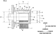
FIG. 2 is a cross section of the guide roller and the roller cover shown inFIG. 1 , which is taken in the axial direction. -
FIG. 3 is a cross section taken along the line III-III inFIG. 2 . -
FIG. 4 corresponds toFIG. 2 and shows an analytical model for calculating power consumption when the inner diameter of the roller cover is longer than the outer diameter of a flange portion of the guide roller. -
FIG. 5 corresponds toFIG. 3 and shows an analytical model for calculating power consumption when the inner diameter of the roller cover is longer than the outer diameter of the flange portion of the guide roller. -
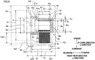
FIG. 6 corresponds toFIG. 2 and shows an analytical model for calculating power consumption when the inner diameter of the roller cover is equal to or shorter than the outer diameter of the flange portion of the guide roller. -
FIG. 7(a) is a table showing analysis results of the relationship between the inner diameter of the roller cover and the power consumption in Examples 1 to 3 and Comparative Examples 1 to 6, whereasFIG. 7(b) graphically shows the table ofFIG. 7(a) . -
FIG. 8(a) is a block diagram of an experimental apparatus for measuring the power consumption of a motor by which the guide roller is driven, whereasFIG. 8(b) is a table showing experimentation results of the relationship between the presence/absence of the roller cover and the power consumption. - The following will describe a preferred embodiment of the present invention.
- As shown in
FIG. 1 , the spun yarn take-up apparatus 1 includes a spunyarn drawing apparatus 3 and ayarn winding apparatus 4. Aspinning apparatus 2 is provided above the spun yarn take-up apparatus 1. A molten fibrous material such as polyester, which is continuously spun out from a spinneret of thespinning apparatus 2, is solidified by cooling air blown onto the material at acooling cylinder 5, with the result that yarns Y are formed. The spunyarn drawing apparatus 3 is provided below thecooling cylinder 5 to draw the yarns Y coming down from thecooling cylinder 5. Theyarn winding apparatus 4 is configured to formwound packages 9 by winding the yarns Y drawn by the spunyarn drawing apparatus 3 ontobobbins 29. Hereinafter, a left-right direction inFIG. 1 , which is orthogonal to an up-down direction, will be referred to as "left-right direction", and "leftward" and "rightward" in the left-right direction are defined as shown inFIG. 1 for facilitating explanation. Furthermore, a direction which is orthogonal to the up-down direction, the left-right direction, and the sheet ofFIG. 1 will be referred to as "front-rear direction", and a direction orthogonal to the sheet ofFIG. 1 and toward the viewer ofFIG. 1 will be referred to as "forward" whereas a direction orthogonal to the sheet ofFIG. 1 and away from the viewer ofFIG. 1 will be referred to as "rearward". - The spun
yarn drawing apparatus 3 includes anoil guide 6 and a heating-drawing unit 7. Theoil guide 6 is configured to apply oil to each of the yarns Y spun out from thespinning apparatus 2. The yarns Y to which oil has been applied by theoil guide 6 are sent to the heating-drawing unit 7 via aguide roller 17. - The heating-drawing unit 7 includes a
thermal insulation box 16 and fivegodet rollers 11a to 11e housed in thethermal insulation box 16. Thethermal insulation box 16 is a box made of a heat insulating material. In a right side wall member of thethermal insulation box 16, ayarn inlet 16a through which the yarns Y are introduced into thethermal insulation box 16 and ayarn outlet 16b through which the yarns Y go outside from thethermal insulation box 16 are formed. Theyarn inlet 16a is formed at a lower end portion of the side wall member of thethermal insulation box 16, whereas theyarn outlet 16b is formed at an upper end portion of the side wall member of thethermal insulation box 16. - The
godet rollers 11a to 11e are rollers which are long in the front-rear direction. Among the fivegodet rollers 11a to 11e, thegodet roller 11a is provided in the vicinity of a bottom portion of thethermal insulation box 16. Above thisgodet roller 11a, the remaining fourgodet rollers 11b to 11e are arranged to form left and right columns which are staggered. The yarns Y introduced into thethermal insulation box 16 through theyarn inlet 16a are wound onto the fivegodet rollers 11a to 11e in order. The yarns Y are wound onto the lowest godet roller 11, then onto the second lowest godet roller 11, and so on. The yarns Y are wound onto each of the fivegodet rollers 11a to 11e at a wining angle of less than 270 degrees. On each of thegodet rollers 11a to 11e, the yarns Y are not wound more than once. As the yarns Y are conveyed in order by the fivegodet rollers 11a to 11e, the yarns Y run from theyarn inlet 16a to theyarn outlet 16b along a meandering and non-crossing yarn path which is on a plane which is in parallel to the sheet ofFIG. 1 . - Each of the five
godet rollers 11a to 11e is rotationally driven by an unillustrated motor. Each of the fivegodet rollers 11a to 11e is a yarn heating roller including a heater therein. - Among the five godet rollers 11, the lower three
godet rollers 11a to 11c on the upstream in the yarn running direction are yarn heating rollers for preliminarily heating the yarns Y to a drawable temperature. When the yarns are formed of polyester fibers, the glass transition temperature of the yarns Y is about 80 degrees centigrade, and hence the heating temperatures (roller surface temperatures) of the threegodet rollers 11a to 11c are set at temperatures (e.g., 80 to 95 degrees centigrade) slightly higher than the glass transition temperature. Meanwhile, the upper twogodet rollers godet rollers godet rollers 11a to 11c. The yarn feeding speeds of the upper twogodet rollers godet rollers 11a to 11c. - The yarns Y introduced into the
thermal insulation box 16 are, to begin with, preliminarily heated to the drawable temperature, i.e., the glass transition temperature while the yarns Y are conveyed by the lower threegodet rollers 11a to 11c. The yarns Y having been preliminarily heated to the glass transition temperature are then drawn on account of a yarn feeding speed difference between the twogodet rollers godet rollers thermal insulation box 16 through theyarn outlet 16b, and are then sent to theyarn winding apparatus 4 by theguide roller 18. Theguide roller 18 and a later-describedroller cover 40 covering theguide roller 18 will be detailed later. - The
yarn winding apparatus 4 is provided below the spunyarn drawing apparatus 3. Theyarn winding apparatus 4 includes abobbin holder 27 and acontact roller 28. Thebobbin holder 27 is long in the front-rear direction, is column-shaped, and is rotationally driven by an unillustrated motor. To thisbobbin holder 27,bobbins 29 are attached to be lined up along the axis of thebobbin holder 27. Theyarn winding apparatus 4 is configured to formwound packages 9 by simultaneously winding the yarns Y onto thebobbins 29 by rotating thebobbin holder 27. Thecontact roller 28 is a roller which is long in the front-rear direction. Thecontact roller 28 adjusts the shape of each of the wound packages 9 in such a way that thecontact roller 28 makes contact with the surface of each of the wound packages 9 and applies a predetermined contact pressure thereto. - The following will describe the
guide roller 18 and theroller cover 40. As shown inFIG. 1 to FIG. 3 , theguide roller 18 is, for example, a roller which is long in the front-rear direction and is about 110mm in outer diameter Dr.The guide roller 18 is substantially identical in height with theyarn outlet 16b of thethermal insulation box 16. Onto theguide roller 18, the yarns Y sent from thethermal insulation box 16 are wound. The yarns Y are wound onto theguide roller 18 at a winding angle θ of, for example, 90 degrees. Theguide roller 18 forwards the yarns Y from thethermal insulation box 16 toward theyarn winding apparatus 4 which is provided below theguide roller 18. At a base end portion of theguide roller 18, aflange portion 31 is provided. The outer diameter Df (e.g., about 160mm) of theflange portion 31 is longer than the outer diameter Dr of theguide roller 18. Amotor 32 is attached to theflange portion 31. Theguide roller 18 is rotationally driven by themotor 32. Themotor 32 rotationally drives theguide roller 18 at a rotation speed with which the running speed of the outercircumferential surface 18a of theguide roller 18 is not lower than 1000m/min and not higher than 6000m/min. - The
guide roller 18 is covered with theroller cover 40. Theroller cover 40 is made of, for example, a synthetic resin material and a metal material, and is attached to aframe 51 of the spun yarn take-upapparatus 1 to which theguide roller 18 is attached. Theroller cover 40 includes afirst part 41, asecond part 42, and athird part 43. - The
first part 41 is formed to be cylindrical in shape (i.e., aninner wall surface 41a is circular in shape when viewed in the direction along the axis of the guide roller 18), and is provided to surround the outercircumferential surface 18a of theguide roller 18. Thefirst part 41 and theguide roller 18 are coaxial and share the same axis J as the central axis. The inner diameter Dc of thefirst part 41 is 1.6 times or more as long as and 1.9 times or less as long as the outer diameter Dr of theguide roller 18. To put it differently, the distance (=Dc/2) from the axis J to theinner wall surface 41a at every part thereof is 1.6 times or more as long as and 1.9 times or less as long as the radius (=Dr/2) of theguide roller 18. For example, while the outer diameter Dr of theguide roller 18 is about 110mm, the inner diameter Dc of thefirst part 41 is equal to or longer than 190mm and equal to or shorter than 220mm. In the present embodiment, a difference (=[Dc/2] - [Dr/2]) between the distance from theinner wall surface 41a to the axis J and the radius of theguide roller 18 is equal to or longer than 40mm and equal to or shorter than 55mm. This difference is constant at every part of theinner wall surface 41a. On account of the difference between the outer diameter Dr of theguide roller 18 and the inner diameter Dc of thefirst part 41, agap 46 is formed between the outercircumferential surface 18a of theguide roller 18 and theinner wall surface 41a of thefirst part 41 so that the distance C between the outercircumferential surface 18a and theinner wall surface 41a is equal to or longer than 40mm and equal to or shorter than 55mm. In the present embodiment, the distance C is constant at every part of thegap 46. - The
first part 41 extends along the entire length of theguide roller 18 in the axial direction of theguide roller 18, and the front end of thefirst part 41 is positioned forward of the leading end of theguide roller 18. At a left end portion of thefirst part 41, ayarn inlet 44 is formed to be substantially identical in height with the upper end of theguide roller 18. At a lower end portion of thefirst part 41, ayarn outlet 45 is formed to be substantially identical in position with the right end of theguide roller 18 in the left-right direction. The yarns Y coming out to the outside of thethermal insulation box 16 from thegodet roller 11e pass theyarn inlet 44 and are then introduced into a space inside theroller cover 40, where theguide roller 18 is provided. The yarns Y conveyed by theguide roller 18 go outside from theroller cover 40 through theyarn outlet 45, and are then sent to theyarn winding apparatus 4. Each of theyarn inlet 44 and theyarn outlet 45 is long in the axial direction of theguide roller 18. For example, the length Ls of each of theseinlet 44 andoutlet 45 is about 134mm in the axial direction of theguide roller 18, and the width Ws thereof is about 10mm. - In the front-rear direction, the
second part 42 faces aleading end surface 18b of theguide roller 18. Thesecond part 42 is circular in shape and is substantially identical in diameter with thefirst part 41 when viewed in the axial direction of theguide roller 18. Thesecond part 42 is connected to a front end portion of thefirst part 41. Thethird part 43 is provided at a rear end portion of thefirst part 41. Thethird part 43 juts outward from thefirst part 41 in the radial direction of theguide roller 18, and is substantially rectangular in shape when viewed in the axial direction of theguide roller 18. Thethird part 43 is fixed to theframe 51 by an unillustrated bolt or the like. - In the present embodiment, as the
roller cover 40 is attached to theframe 51, theguide roller 18 is provided in a space surrounded by theframe 51 and the roller cover 40 (thefirst part 41 and the second part 42). This space communicates with the outside only at theyarn inlet 44 and theyarn outlet 45. - When the yarns Y are conveyed by the rotation of the
guide roller 18, theguide roller 18 stirs circumambient air. In this connection, when power consumption which is energy consumed for the stirring of the circumambient air by theguide roller 18 is large, the power consumption of themotor 32 is disadvantageously large. In the present embodiment, because theguide roller 18 is covered with theroller cover 40, an amount of air surrounding the outercircumferential surface 18a of theguide roller 18 is reduced, and hence the power consumption is reduced. - In this regard, to simply reduce an amount of air surrounding the outer
circumferential surface 18a of theguide roller 18, it appears to be preferable to minimize the capacity of thegap 46 between the outercircumferential surface 18a of theguide roller 18 and theinner wall surface 41a of thefirst part 41 by shortening the inner diameter Dc of thefirst part 41 of theroller cover 40 as much as possible on condition that the inner diameter Dc is longer than the outer diameter Dr of theguide roller 18. - However, in the present embodiment, the
yarn inlet 44 for introducing the yarns Y and theyarn outlet 45 for taking the yarns Y out are formed at thefirst part 41. When the yarns Y are introduced into the space in theroller cover 40 through theyarn inlet 44, an airflow (accompanied flow) generated around the running yarns Y flows into the space in theroller cover 40 through theyarn inlet 44, together with the yarns Y. Meanwhile, when the yarns Y go out from theroller cover 40 through theyarn outlet 45, an airflow (accompanied flow) generated around the running yarns Y flows out from theroller cover 40 through theyarn outlet 45, together with the yarns Y. The smaller the capacity of thegap 46 is, the more the accompanied flows influence on an airflow in thegap 46. For this reason, when the capacity of thegap 46 at thefirst part 41 is too small (i.e., when the inner diameter Dc is too short), the airflow in thegap 46 is significantly disturbed due to an influence of the accompanied flows, with the result that the power consumption is disadvantageously increased. - In consideration of this, in the present embodiment, the inner diameter Dc of the
first part 41 is arranged to be 1.6 times or more as long as and 1.9 times or less as long as the outer diameter Dr of theguide roller 18, as described above, and hence thegap 46 which is equal to or longer than 40mm and equal to or shorter than 55mm is formed between the outercircumferential surface 18a of theguide roller 18 and theinner wall surface 41a of thefirst part 41. With this arrangement, the power consumption is effectively reduced, as analysis results and experimentation results described below indicate. - In the present embodiment, because the
first part 41 is formed to be cylindrical in shape and thefirst part 41 and theguide roller 18 share the same central axis, the distance between the outercircumferential surface 18a of theguide roller 18 and theinner wall surface 41a of thefirst part 41 is constant, and hence stabilization of the airflow in thegap 46 is facilitated. This makes it possible to effectively reduce the power consumption. - In the spun yarn take-up
apparatus 1, the running speed of the outercircumferential surface 18a of theguide roller 18 is high, i.e., is about 1000m/min or higher and 6000m/min or lower. The power consumption is therefore high without theroller cover 40. In the present embodiment, theroller cover 40 is sized as described above. The power consumption is therefore effectively reduced as the analysis results and experimentation results described below indicate. - The following will describe specific examples of the present invention.
- In Examples 1 to 3 and Comparative Examples 1 and 2, the power consumption was calculated by using an analytical model shown in
FIG. 4 andFIG. 5 , corresponding to aguide roller 18 and aroller cover 40 identical with those in the embodiment above. In Comparative Examples 3 to 5, the power consumption was calculated by using an analytical model shown inFIG. 6 . - In the analytical model shown in
FIG. 4 andFIG. 5 , the outer diameter Dr of theguide roller 18 was 110mm and the outer diameter Df of theflange portion 31 was 160mm. The entire length Lr in the axial direction of theguide roller 18 inclusive of theflange portion 31 was 217.5mm, the length Lc of the space formed by theroller cover 40 and theframe 51 was 237.5mm in the axial direction of theguide roller 18, and the distance K1 between theleading end surface 18b of theguide roller 18 and thesecond part 42 of theroller cover 40 was 10mm. The height H of theframe 51 was 240mm. The thickness Tc of theroller cover 40 was 10mm. Furthermore, in each of theyarn inlet 44 and theyarn outlet 45, the length Ls was 134mm in the axial direction of theguide roller 18 and the width Ws thereof was 10mm. - In the analytical model of
FIG. 4 andFIG. 5 , the inner diameter Dc of thefirst part 41 was constant. In Examples 1 to 3, the inner diameters Dc were 220mm, 200mm, and 190mm, respectively. In Comparative Examples 1 and 2, the inner diameters Dc were 280mm and 240mm, respectively. - In the meanwhile, in the analytical model of
FIG. 6 , thefirst part 41 was arranged such that the inner diameter Db of a part surrounding theflange portion 31 of theguide roller 18 was 180mm whereas the inner diameter Dc of a part surrounding a portion which was on the leading end side as compared to theflange portion 31 was shorter than the inner diameter Db. In Comparative Examples 3 to 5, the inner diameters Dc were 160mm, 140mm, and 120mm, respectively. Furthermore, in the axial direction of theguide roller 18, the distance K3 between the leading end of theflange portion 31 and the leading end of the inner wall surface of the part surrounding theflange portion 31 was 10mm. The lengths in the analytical model ofFIG. 6 other than the above were identical with those in the analytical model ofFIG. 4 andFIG. 5 . Note that the analytical model ofFIG. 6 was used in Comparative Examples 3 to 5 in place of the analytical model ofFIG. 4 andFIG. 5 because the inner diameter Dc was equal to or shorter than the outer diameter Df (=160mm) of theflange portion 31 and hence theguide roller 18 could not be housed in theroller cover 40 in the analytical model ofFIG. 4 andFIG. 5 . - In Comparative Example 6, the power consumption was calculated by using an analytical model which was identical with the analytical model of
FIG. 4 andFIG. 5 except that theroller cover 40 was not provided. - In Examples 1 to 3 and Comparative Examples 1 to 6, the running speed of the outer
circumferential surface 18a of theguide roller 18 was 5000m/min. Furthermore, as shown inFIG. 4 to FIG. 6 , analysis was performed with the assumption that a band body B having the width Lb of 124mm and the thickness Tb of 0.088mm ran. The band body B was a simplification of 32 yarns Y each of which was 0.088mm in diameter (=83dtex/36f) and which were provided at intervals of 4mm. The distance K4 between an end of the band body B on the leading end side of theguide roller 18 and the leading end of theguide roller 18 was 30mm. The winding angle of the band body B onto theguide roller 18 was 90 degrees. A part of the band body B, which was upstream of a part of the band body B wound onto theguide roller 18, was arranged to extend in parallel to the left-right direction, and the length Lb1 of this part was 120mm. A part of the band body B, which was downstream of the part of the band body B wound onto theguide roller 18, was arranged to extend in parallel to the up-down direction, and the length Lb2 of this part was 120mm. - A circle which was centered at the central axis (axis J) of the
guide roller 18 and had a diameter De (500mm) was set as an exit boundary Ek in the radial direction of theguide roller 18. A line, which was on the side opposite to theframe 51 over the center in the axial direction of theguide roller 18 inclusive of theflange portion 31 and was away from the center in the axial direction of theguide roller 18 inclusive of theflange portion 31 by Le1 (150mm), was set as a front exit boundary Ej1 in the axial direction of theguide roller 18. A line, which was on the same side as theframe 51 with respect to the center in the axial direction of theguide roller 18 inclusive of theflange portion 31 and was away from the center in the axial direction of theguide roller 18 inclusive of theflange portion 31 by Le2 (150mm), was set as a front exit boundary Ej2 in the axial direction of theguide roller 18. - In addition to the above, in regard to an airflow, a k-ε turbulence model was applied to each of governing equations (1) and (2) below, discretization was done by a finite volume method, and approximate solutions were calculated by an iteration method. The equation (1) indicates that the fluid is incompressible fluid. The equation (2) is a RANS equation. In the analyses in Examples 1 to 3 and Comparative Examples 1 to 6, the front-rear direction was an x direction, the left-right direction was a y direction, and the up-down direction was a z direction.
[Equations 1]

- P : Pressure
- t : Time
- x,y,z : Coordinate axes
-
U = (u,v,w) : Average speed vector - U : Average speed component
- u',v',w': Variation components of u, v, and w
- ρ : Air density
- µ : Coefficient of kinematic viscosity
- In addition to the above, a torque M acting on the
guide roller 18 was obtained by a numerical calculation, and a power consumption L was calculated by L=MQ. Ω indicates an angular speed of theguide roller 18. The torque M was calculated by using a pressure P obtained by numerical calculation by the equations (1) and (2) and by using equations (3), (4), and (5) below. The pressure P obtained by numerical calculation by the equations (1) and (2) corresponds to Pf in the equation (4).
[Equations 2]


- rf : Position of element f relative to X0 (X0 is a point where moment is obtained)
-
a : Vector defining axis passing X0 -

-

- Pf : Pressure of element f
- Pref : Reference pressure
-
A f : Vector of area of element -
T f : Stress tensor of element f - The analyses were done by using "STAR-CCM+" which was CDF software produced by CD-adapco. FIG. 7(a) and FIG. 7(b) show the analysis results of Examples 1 to 3 and Comparative Examples 1 to 6. As shown in FIG. 7(a) and FIG. 7(b), as a result of comparison between (i) Comparative Example 6 and (ii) Examples 1 to 3 and Comparative Examples 1 to 5, it is found that the power consumption is reduced when the
roller cover 40 covering theguide roller 18 is provided, as compared to cases where theroller cover 40 is not provided. Furthermore, as a result of comparison between Examples 1 to 3 and Comparative Examples 1 to 5, it is found that, when theroller cover 40 is provided, the power consumption is reduced by at least 25% when the inner diameter Dc of thefirst part 41 is equal to or longer than 190mm and equal to or shorter than 220mm (i.e., the difference between the distance Dc/2 from theinner wall surface 41a to the axis J and the radius Dr/2 of theguide roller 18 is equal to or longer than 40mm and equal to or shorter than 55mm). - In Example 4, by using an apparatus shown in
FIG. 8(a) , the power consumption of themotor 32 rotationally driving theguide roller 18 covered with theroller cover 40 as in the embodiment above was measured. To be more specific, in Example 4, an AC voltage supplied from anAC power source 101 was transformed by atransformer 102, the voltage was converted to a DC voltage by aninverter 103, and themotor 32 was rotationally driven by the DC voltage output to themotor 32. In Example 4, furthermore, apower meter 104 was connected between theinverter 103 and themotor 32 and the power consumption of themotor 32 was measured by thepower meter 104. - In Example 4, the outer diameter Dr of the
guide roller 18 was 110mm, the outer diameter Df of theflange portion 31 was 160mm, and the inner diameter Dc of thefirst part 41 was 190mm. Furthermore, the entire length Lr in the axial direction of theguide roller 18 inclusive of theflange portion 31 was 218mm, and the length Lc of the space formed by theroller cover 40 and theframe 51 was 248mm in the axial direction of theguide roller 18. The height of theframe 51 was 240mm. The thickness Tc of theroller cover 40 was 10mm. Furthermore, in each of theyarn inlet 44 and theyarn outlet 45, the length Ls was 134mm in the axial direction of theguide roller 18 and the width Ws thereof was 10mm. In Example 4, 32 yarns Y each of which was 0.088mm (=83dtex/36f) in diameter and made of polyester fibers ran at intervals of 4mm. Furthermore, the winding angle of the yarn Y onto theguide roller 18 was 90 degrees. Furthermore, in Example 4, themotor 32 was rotationally driven so that the running speed of the outercircumferential surface 18a of theguide roller 18 was about 5000m/min (an average speed was 4921m/min). - The power consumption of the
motor 32 was measured in Comparative Example 7 on the same conditions as in Example 4 except that theroller cover 40 was detached. -
FIG. 8(b) shows the experimentation results of Example 4 and Comparative Example 7. The "measured power" inFIG. 8(b) indicates the power consumption of themotor 32 measured by thepower meter 104 inFIG. 8(a) . The power consumption inFIG. 8(b) was calculated by subtracting, from the power consumption measured by thepower meter 104, energy (≅79W) equivalent to a loss by themotor 32 and energy (≅110W) equivalent to a loss by the tension of the yarns Y. The energy equivalent to the loss by themotor 32 is, for example, obtained by measuring the power consumption when themotor 32 is independently driven. The energy equivalent to the loss by the tension of the yarns Y is calculated, for example, based on a difference between the power consumption in Comparative Example 7 and the power consumption (e.g., 175W) measured by thepower meter 104 when themotor 32 is driven while theroller cover 40 is detached and the yarns Y do not run. - As a result of comparison between Example 4 and Comparative Example 7 in
FIG. 8(b) , it is found that the power consumption is effectively reduced by providing, on theguide roller 18, theroller cover 40 in which the inner diameter Dc of thefirst part 41 is 190mm. As a result of comparison between Example 4 and Comparative Example 7 and the above-described Example 3 and Comparative Example 6, it is understood that the analysis results are more or less matched with the experimentation results. - In this regard, the analysis results in Examples 1 to 3 and Comparative Examples 1 to 6 and the experimentation results in Example 4 and Comparative Example 7 were obtained when the running speed of the outer
circumferential surface 18a of theguide roller 18 was 5000m/min. When the running speed of the outercircumferential surface 18a of theguide roller 18 is varied, the magnitude of the airflow generated in thegap 46 is varied, too. However, when the shape of theguide roller 18, the shape of theroller cover 40, and the rotational direction of theguide roller 18 remain the same, the type of the airflow in thegap 46 is similar. On this account, in Examples 1 to 3 and Comparative Examples 1 to 6 and Example 4 and Comparative Example 7, it is assumed that results similar to the above are obtained when the running speed of the outercircumferential surface 18a of theguide roller 18 is lower than or higher than 5000m/min. - A preferred embodiment of the present invention has been described. It should be noted that the present invention is not limited to the above-described embodiment and examples, and various changes can be made herein without departing from the spirit and scope of the invention as defined by the appended claims.
- In the embodiment above, the running speed of the outer
circumferential surface 18a of theguide roller 18 is equal to or higher than 1000m/min and equal to lower than 6000m/min. The disclosure, however, is not limited to this arrangement. The running speed of the outercircumferential surface 18a of theguide roller 18 may be lower than 1000m/min or higher than 6000m/min. As described above, even if the running speed of the outercircumferential surface 18a of theguide roller 18 is lower than 1000m/min or higher than 6000m/min, it is considered that results similar to Examples 1 to 3 and Comparative Examples 1 to 6 and Example 4 and Comparative Example 7 described above are obtained. - In the embodiment above, the
first part 41 of theroller cover 40 is cylindrical in shape, theinner wall surface 41a of thefirst part 41 is circular and centered at the axis of theguide roller 18 when viewed in the axial direction of theguide roller 18, and the distance between the outercircumferential surface 18a of theguide roller 18 and theinner wall surface 41a of thefirst part 41 is constant at any part of thegap 46. The disclosure, however, is not limited to this. For example, theinner wall surface 41a of thefirst part 41 may not be circular in shape, and may be polygonal or elliptical in shape when viewed in the axial direction of theguide roller 18. Also in these cases, when the distance from the axis of theguide roller 18 to theinner wall surface 41a at every part of theinner wall surface 41a is 1.6 times or more as long as and 1.9 times or less as long as the radius Dr/2 of theguide roller 18, or when the difference between the distance from the axis J to theinner wall surface 41a of thefirst part 41 and the radius Dr/2 of theguide roller 18 is equal to or longer than 40mm and equal to or shorter than 55mm at every part of theinner wall surface 41a, variations in distance between the outercircumferential surface 18a of theguide roller 18 and theinner wall surface 41a of thefirst part 41 are not so great. As a result, the airflow generated in thegap 46 is similar to the airflow when theinner wall surface 41a is circular, and hence the power consumption is effectively reduced. - While in the embodiment above the space in the
roller cover 40 communicates with the outside only via theyarn inlet 44 and theyarn outlet 45, the disclosure is not limited to this arrangement. In theroller cover 40, a hole or notch through which the space in the roller cover communicates with the outside may be formed in addition to theyarn inlet 44 and theyarn outlet 45. Such a hole or notch is small enough not to influence on the airflow in the space. - While in the embodiment above the
roller cover 40 is provided for theguide roller 18 by which the yarns Y coming out from thethermal insulation box 16 is sent toward theyarn winding apparatus 4, the disclosure is not limited to this arrangement. For example, a roller cover may be provided for theguide roller 17 or thegodet rollers 11a to 11e. When the spun yarn take-upapparatus 1 is provided with another roller for conveying yarns in addition to thegodet rollers 11a to 11e and theguide rollers - The descriptions above presuppose that the present invention is applied to a spun yarn take-up apparatus in which yarns spun out from a spinning apparatus are drawn and then wound, the disclosure is not limited to this arrangement. The present invention may be applied to a processing apparatus including a yarn conveyance roller, which is not a spun yarn take-up apparatus.
Claims (6)
- A yarn processing apparatus comprising:a yarn conveyance roller conveying yarns: anda roller cover covering the yarn conveyance roller,the roller cover including:a first part which is provided to surround the outer circumferential surface of the yarn conveyance roller, a yarn inlet through which yarns are introduced from outside into a space in which the yarn conveyance roller is provided and a yarn outlet through which the yarns in the space are taken out being formed in the first part; anda second part which faces a leading end surface of the yarn conveyance roller in a direction along an axis of the yarn conveyance roller and is connected to the first part,the distance from the central axis of the yarn conveyance roller to an inner wall surface of the first part being 1.6 times or more as long as and 1.9 times or less as long as the radius of the yarn conveyance roller, at every part of the inner wall surface.
- A yarn processing apparatus comprising:a yarn conveyance roller conveying yarns: anda roller cover covering the yarn conveyance roller,the roller cover including:a first part which is provided to surround the outer circumferential surface of the yarn conveyance roller, a yarn inlet through which yarns are introduced from outside into a space in which the yarn conveyance roller is provided and a yarn outlet through which the yarns in the space are taken out being formed in the first part; anda second part which faces a leading end surface of the yarn conveyance roller in a direction along an axis of the yarn conveyance roller and is connected to the first part,a difference between the distance from the central axis of the yarn conveyance roller to an inner wall surface of the first part and the radius of the yarn conveyance roller being equal to or longer than 40mm and equal to or shorter than 55mm, at every part of the inner wall surface.
- The yarn processing apparatus according to claim 1 or 2, wherein, the inner wall surface of the roller cover is circular in shape and centered at the axis of the yarn conveyance roller, when viewed in the direction along the axis of the yarn conveyance roller.
- The yarn processing apparatus according to any one of claims 1 to 3, wherein, the running speed of the outer circumferential surface of the yarn conveyance roller is equal to or higher than 1000m/min and equal to or lower than 6000m/min.
- A roller cover covering a yarn conveyance roller by which yarns are conveyed, the roller cover comprising:a first part which is provided to surround the outer circumferential surface of the yarn conveyance roller, a yarn inlet through which yarns are introduced from outside into a space in which the yarn conveyance roller is provided and a yarn outlet through which the yarns in the space are taken out being formed in the first part; anda second part which faces a leading end surface of the yarn conveyance roller in a direction along an axis of the yarn conveyance roller and is connected to the first part,the distance from the central axis of the yarn conveyance roller to an inner wall surface of the first part being 1.6 times or more as long as and 1.9 times or less as long as the radius of the yarn conveyance roller, at every part of the inner wall surface.
- A roller cover covering a yarn conveyance roller by which yarns are conveyed, the roller cover comprising:a first part which is provided to surround the outer circumferential surface of the yarn conveyance roller, a yarn inlet through which yarns are introduced from outside into a space in which the yarn conveyance roller is provided and a yarn outlet through which the yarns in the space are taken out being formed in the first part; anda second part which faces a leading end surface of the yarn conveyance roller in a direction along an axis of the yarn conveyance roller and is connected to the first part,a difference between the distance from the central axis of the yarn conveyance roller to an inner wall surface of the first part and the radius of the yarn conveyance roller being equal to or longer than 40mm and equal to or shorter than 55mm, at every part of the inner wall surface.
Applications Claiming Priority (1)
| Application Number | Priority Date | Filing Date | Title |
|---|---|---|---|
| JP2017096963A JP6998132B2 (en) | 2017-05-16 | 2017-05-16 | Thread processing equipment and roller cover |
Publications (2)
| Publication Number | Publication Date |
|---|---|
| EP3403960A1 true EP3403960A1 (en) | 2018-11-21 |
| EP3403960B1 EP3403960B1 (en) | 2020-06-17 |
Family
ID=62142977
Family Applications (1)
| Application Number | Title | Priority Date | Filing Date |
|---|---|---|---|
| EP18171191.2A Active EP3403960B1 (en) | 2017-05-16 | 2018-05-08 | Yarn processing apparatus and roller cover |
Country Status (3)
| Country | Link |
|---|---|
| EP (1) | EP3403960B1 (en) |
| JP (1) | JP6998132B2 (en) |
| CN (1) | CN108866659B (en) |
Citations (4)
| Publication number | Priority date | Publication date | Assignee | Title |
|---|---|---|---|---|
| JPS6111661U (en) * | 1984-06-25 | 1986-01-23 | 東レ株式会社 | Rotating roll accompanying airflow prevention device |
| DE102013223663A1 (en) * | 2012-11-22 | 2014-05-22 | Tmt Machinery, Inc. | Yarn receiving device has heat insulating box which is provided for receiving preheating rollers and heating cure rollers which heats up yarn at stretching temperature, and is covered by protective covering |
| WO2016005063A1 (en) * | 2014-07-08 | 2016-01-14 | Oerlikon Textile Gmbh & Co. Kg | Method and device for producing synthetic fully drawn yarns |
| EP3064621A1 (en) * | 2015-03-06 | 2016-09-07 | TMT Machinery, Inc. | Spun yarn drawing apparatus |
Family Cites Families (10)
| Publication number | Priority date | Publication date | Assignee | Title |
|---|---|---|---|---|
| JPS4839719A (en) * | 1971-09-21 | 1973-06-11 | ||
| JPH0235825Y2 (en) * | 1985-10-04 | 1990-09-28 | ||
| JPH07278990A (en) * | 1994-03-31 | 1995-10-24 | Toray Ind Inc | Yarn heat treatment equipment |
| US5915699A (en) * | 1997-10-24 | 1999-06-29 | E. I. Du Pont De Nemours And Company | Heated enclosure |
| JP4429549B2 (en) * | 2001-06-08 | 2010-03-10 | 帝人ファイバー株式会社 | Heating roller device |
| JP3951871B2 (en) * | 2001-09-20 | 2007-08-01 | 東レ株式会社 | Synthetic fiber manufacturing apparatus and method |
| CN101040074A (en) * | 2004-10-14 | 2007-09-19 | 苏拉有限及两合公司 | Godets for guiding, heating and conveying the filaments |
| JP5735849B2 (en) * | 2011-04-26 | 2015-06-17 | Tmtマシナリー株式会社 | Yarn heating device |
| DE102014012145A1 (en) * | 2014-08-14 | 2016-03-03 | Oerlikon Textile Gmbh & Co. Kg | Apparatus for stripping and drawing a plurality of threads |
| JP6668163B2 (en) * | 2015-05-25 | 2020-03-18 | Tmtマシナリー株式会社 | Yarn heating device |
-
2017
- 2017-05-16 JP JP2017096963A patent/JP6998132B2/en active Active
-
2018
- 2018-05-07 CN CN201810424644.1A patent/CN108866659B/en active Active
- 2018-05-08 EP EP18171191.2A patent/EP3403960B1/en active Active
Patent Citations (5)
| Publication number | Priority date | Publication date | Assignee | Title |
|---|---|---|---|---|
| JPS6111661U (en) * | 1984-06-25 | 1986-01-23 | 東レ株式会社 | Rotating roll accompanying airflow prevention device |
| DE102013223663A1 (en) * | 2012-11-22 | 2014-05-22 | Tmt Machinery, Inc. | Yarn receiving device has heat insulating box which is provided for receiving preheating rollers and heating cure rollers which heats up yarn at stretching temperature, and is covered by protective covering |
| WO2016005063A1 (en) * | 2014-07-08 | 2016-01-14 | Oerlikon Textile Gmbh & Co. Kg | Method and device for producing synthetic fully drawn yarns |
| EP3064621A1 (en) * | 2015-03-06 | 2016-09-07 | TMT Machinery, Inc. | Spun yarn drawing apparatus |
| JP2016164314A (en) | 2015-03-06 | 2016-09-08 | Tmtマシナリー株式会社 | Spinning and drawing equipment |
Also Published As
| Publication number | Publication date |
|---|---|
| EP3403960B1 (en) | 2020-06-17 |
| JP6998132B2 (en) | 2022-01-18 |
| CN108866659B (en) | 2021-10-15 |
| JP2018193631A (en) | 2018-12-06 |
| CN108866659A (en) | 2018-11-23 |
Similar Documents
| Publication | Publication Date | Title |
|---|---|---|
| US5199689A (en) | Transmission line installation | |
| JP6668163B2 (en) | Yarn heating device | |
| US9139464B2 (en) | Method and apparatus for shaping an elongated glass body | |
| KR20150090902A (en) | Methods and apparatus for fabricating glass ribbon of varying widths | |
| TW201510229A (en) | Thermal insulation box | |
| EP3403960B1 (en) | Yarn processing apparatus and roller cover | |
| CN109612302A (en) | Heat Exchanger Piping System | |
| EP0760874B1 (en) | Processing textile structures | |
| CN111432998A (en) | Tempering device for temperature treatment of preforms and method for operating such a tempering device | |
| EP4119707A2 (en) | Cooler and yarn processor | |
| CN113412241A (en) | Glass manufacturing apparatus and method | |
| CN103710769B (en) | Method and apparatus for producing drawn yarn | |
| CN105084107A (en) | Yarn winding device and mark-forming method | |
| EP0900866B1 (en) | Heating arrangement | |
| TW201700417A (en) | Apparatus and methods for processing molten material | |
| EP3064622A1 (en) | Spun yarn drawing apparatus | |
| CN104746154A (en) | Spin drawing apparatus | |
| JP2016145429A (en) | Doubling false twisting machine | |
| JP2019533095A (en) | Method and apparatus for cooling synthetic yarn | |
| EP3758444B1 (en) | Induction heating roller and spun yarn take-up machine | |
| EP0403098A2 (en) | Yarn texturing method and apparatus | |
| EP3929337B1 (en) | Spun yarn drawing apparatus | |
| JP2023070140A (en) | Yarn guide element and yarn clearer for work unit of textile machine with yarn guide element | |
| US20060005525A1 (en) | Method and false twist spindle for false twist texturing | |
| EP0903431A2 (en) | Textile machine arrangement |
Legal Events
| Date | Code | Title | Description |
|---|---|---|---|
| PUAI | Public reference made under article 153(3) epc to a published international application that has entered the european phase |
Free format text: ORIGINAL CODE: 0009012 |
|
| STAA | Information on the status of an ep patent application or granted ep patent |
Free format text: STATUS: THE APPLICATION HAS BEEN PUBLISHED |
|
| AK | Designated contracting states |
Kind code of ref document: A1 Designated state(s): AL AT BE BG CH CY CZ DE DK EE ES FI FR GB GR HR HU IE IS IT LI LT LU LV MC MK MT NL NO PL PT RO RS SE SI SK SM TR |
|
| AX | Request for extension of the european patent |
Extension state: BA ME |
|
| STAA | Information on the status of an ep patent application or granted ep patent |
Free format text: STATUS: REQUEST FOR EXAMINATION WAS MADE |
|
| 17P | Request for examination filed |
Effective date: 20190705 |
|
| RBV | Designated contracting states (corrected) |
Designated state(s): AL AT BE BG CH CY CZ DE DK EE ES FI FR GB GR HR HU IE IS IT LI LT LU LV MC MK MT NL NO PL PT RO RS SE SI SK SM TR |
|
| GRAP | Despatch of communication of intention to grant a patent |
Free format text: ORIGINAL CODE: EPIDOSNIGR1 |
|
| STAA | Information on the status of an ep patent application or granted ep patent |
Free format text: STATUS: GRANT OF PATENT IS INTENDED |
|
| INTG | Intention to grant announced |
Effective date: 20200114 |
|
| GRAS | Grant fee paid |
Free format text: ORIGINAL CODE: EPIDOSNIGR3 |
|
| GRAA | (expected) grant |
Free format text: ORIGINAL CODE: 0009210 |
|
| STAA | Information on the status of an ep patent application or granted ep patent |
Free format text: STATUS: THE PATENT HAS BEEN GRANTED |
|
| AK | Designated contracting states |
Kind code of ref document: B1 Designated state(s): AL AT BE BG CH CY CZ DE DK EE ES FI FR GB GR HR HU IE IS IT LI LT LU LV MC MK MT NL NO PL PT RO RS SE SI SK SM TR |
|
| REG | Reference to a national code |
Ref country code: GB Ref legal event code: FG4D |
|
| REG | Reference to a national code |
Ref country code: CH Ref legal event code: EP |
|
| REG | Reference to a national code |
Ref country code: DE Ref legal event code: R096 Ref document number: 602018005284 Country of ref document: DE |
|
| REG | Reference to a national code |
Ref country code: IE Ref legal event code: FG4D |
|
| REG | Reference to a national code |
Ref country code: AT Ref legal event code: REF Ref document number: 1281061 Country of ref document: AT Kind code of ref document: T Effective date: 20200715 |
|
| PG25 | Lapsed in a contracting state [announced via postgrant information from national office to epo] |
Ref country code: NO Free format text: LAPSE BECAUSE OF FAILURE TO SUBMIT A TRANSLATION OF THE DESCRIPTION OR TO PAY THE FEE WITHIN THE PRESCRIBED TIME-LIMIT Effective date: 20200917 Ref country code: GR Free format text: LAPSE BECAUSE OF FAILURE TO SUBMIT A TRANSLATION OF THE DESCRIPTION OR TO PAY THE FEE WITHIN THE PRESCRIBED TIME-LIMIT Effective date: 20200918 Ref country code: LT Free format text: LAPSE BECAUSE OF FAILURE TO SUBMIT A TRANSLATION OF THE DESCRIPTION OR TO PAY THE FEE WITHIN THE PRESCRIBED TIME-LIMIT Effective date: 20200617 Ref country code: SE Free format text: LAPSE BECAUSE OF FAILURE TO SUBMIT A TRANSLATION OF THE DESCRIPTION OR TO PAY THE FEE WITHIN THE PRESCRIBED TIME-LIMIT Effective date: 20200617 Ref country code: FI Free format text: LAPSE BECAUSE OF FAILURE TO SUBMIT A TRANSLATION OF THE DESCRIPTION OR TO PAY THE FEE WITHIN THE PRESCRIBED TIME-LIMIT Effective date: 20200617 |
|
| REG | Reference to a national code |
Ref country code: LT Ref legal event code: MG4D |
|
| REG | Reference to a national code |
Ref country code: NL Ref legal event code: MP Effective date: 20200617 |
|
| PG25 | Lapsed in a contracting state [announced via postgrant information from national office to epo] |
Ref country code: BG Free format text: LAPSE BECAUSE OF FAILURE TO SUBMIT A TRANSLATION OF THE DESCRIPTION OR TO PAY THE FEE WITHIN THE PRESCRIBED TIME-LIMIT Effective date: 20200917 Ref country code: HR Free format text: LAPSE BECAUSE OF FAILURE TO SUBMIT A TRANSLATION OF THE DESCRIPTION OR TO PAY THE FEE WITHIN THE PRESCRIBED TIME-LIMIT Effective date: 20200617 Ref country code: LV Free format text: LAPSE BECAUSE OF FAILURE TO SUBMIT A TRANSLATION OF THE DESCRIPTION OR TO PAY THE FEE WITHIN THE PRESCRIBED TIME-LIMIT Effective date: 20200617 Ref country code: RS Free format text: LAPSE BECAUSE OF FAILURE TO SUBMIT A TRANSLATION OF THE DESCRIPTION OR TO PAY THE FEE WITHIN THE PRESCRIBED TIME-LIMIT Effective date: 20200617 |
|
| REG | Reference to a national code |
Ref country code: AT Ref legal event code: MK05 Ref document number: 1281061 Country of ref document: AT Kind code of ref document: T Effective date: 20200617 |
|
| PG25 | Lapsed in a contracting state [announced via postgrant information from national office to epo] |
Ref country code: AL Free format text: LAPSE BECAUSE OF FAILURE TO SUBMIT A TRANSLATION OF THE DESCRIPTION OR TO PAY THE FEE WITHIN THE PRESCRIBED TIME-LIMIT Effective date: 20200617 Ref country code: NL Free format text: LAPSE BECAUSE OF FAILURE TO SUBMIT A TRANSLATION OF THE DESCRIPTION OR TO PAY THE FEE WITHIN THE PRESCRIBED TIME-LIMIT Effective date: 20200617 |
|
| PG25 | Lapsed in a contracting state [announced via postgrant information from national office to epo] |
Ref country code: AT Free format text: LAPSE BECAUSE OF FAILURE TO SUBMIT A TRANSLATION OF THE DESCRIPTION OR TO PAY THE FEE WITHIN THE PRESCRIBED TIME-LIMIT Effective date: 20200617 Ref country code: PT Free format text: LAPSE BECAUSE OF FAILURE TO SUBMIT A TRANSLATION OF THE DESCRIPTION OR TO PAY THE FEE WITHIN THE PRESCRIBED TIME-LIMIT Effective date: 20201019 Ref country code: ES Free format text: LAPSE BECAUSE OF FAILURE TO SUBMIT A TRANSLATION OF THE DESCRIPTION OR TO PAY THE FEE WITHIN THE PRESCRIBED TIME-LIMIT Effective date: 20200617 Ref country code: IT Free format text: LAPSE BECAUSE OF FAILURE TO SUBMIT A TRANSLATION OF THE DESCRIPTION OR TO PAY THE FEE WITHIN THE PRESCRIBED TIME-LIMIT Effective date: 20200617 Ref country code: CZ Free format text: LAPSE BECAUSE OF FAILURE TO SUBMIT A TRANSLATION OF THE DESCRIPTION OR TO PAY THE FEE WITHIN THE PRESCRIBED TIME-LIMIT Effective date: 20200617 Ref country code: RO Free format text: LAPSE BECAUSE OF FAILURE TO SUBMIT A TRANSLATION OF THE DESCRIPTION OR TO PAY THE FEE WITHIN THE PRESCRIBED TIME-LIMIT Effective date: 20200617 Ref country code: SM Free format text: LAPSE BECAUSE OF FAILURE TO SUBMIT A TRANSLATION OF THE DESCRIPTION OR TO PAY THE FEE WITHIN THE PRESCRIBED TIME-LIMIT Effective date: 20200617 Ref country code: EE Free format text: LAPSE BECAUSE OF FAILURE TO SUBMIT A TRANSLATION OF THE DESCRIPTION OR TO PAY THE FEE WITHIN THE PRESCRIBED TIME-LIMIT Effective date: 20200617 |
|
| PG25 | Lapsed in a contracting state [announced via postgrant information from national office to epo] |
Ref country code: SK Free format text: LAPSE BECAUSE OF FAILURE TO SUBMIT A TRANSLATION OF THE DESCRIPTION OR TO PAY THE FEE WITHIN THE PRESCRIBED TIME-LIMIT Effective date: 20200617 Ref country code: PL Free format text: LAPSE BECAUSE OF FAILURE TO SUBMIT A TRANSLATION OF THE DESCRIPTION OR TO PAY THE FEE WITHIN THE PRESCRIBED TIME-LIMIT Effective date: 20200617 Ref country code: IS Free format text: LAPSE BECAUSE OF FAILURE TO SUBMIT A TRANSLATION OF THE DESCRIPTION OR TO PAY THE FEE WITHIN THE PRESCRIBED TIME-LIMIT Effective date: 20201017 |
|
| REG | Reference to a national code |
Ref country code: DE Ref legal event code: R097 Ref document number: 602018005284 Country of ref document: DE |
|
| PLBE | No opposition filed within time limit |
Free format text: ORIGINAL CODE: 0009261 |
|
| STAA | Information on the status of an ep patent application or granted ep patent |
Free format text: STATUS: NO OPPOSITION FILED WITHIN TIME LIMIT |
|
| PG25 | Lapsed in a contracting state [announced via postgrant information from national office to epo] |
Ref country code: DK Free format text: LAPSE BECAUSE OF FAILURE TO SUBMIT A TRANSLATION OF THE DESCRIPTION OR TO PAY THE FEE WITHIN THE PRESCRIBED TIME-LIMIT Effective date: 20200617 |
|
| 26N | No opposition filed |
Effective date: 20210318 |
|
| PG25 | Lapsed in a contracting state [announced via postgrant information from national office to epo] |
Ref country code: SI Free format text: LAPSE BECAUSE OF FAILURE TO SUBMIT A TRANSLATION OF THE DESCRIPTION OR TO PAY THE FEE WITHIN THE PRESCRIBED TIME-LIMIT Effective date: 20200617 |
|
| REG | Reference to a national code |
Ref country code: CH Ref legal event code: PL |
|
| PG25 | Lapsed in a contracting state [announced via postgrant information from national office to epo] |
Ref country code: CH Free format text: LAPSE BECAUSE OF NON-PAYMENT OF DUE FEES Effective date: 20210531 Ref country code: MC Free format text: LAPSE BECAUSE OF FAILURE TO SUBMIT A TRANSLATION OF THE DESCRIPTION OR TO PAY THE FEE WITHIN THE PRESCRIBED TIME-LIMIT Effective date: 20200617 Ref country code: LI Free format text: LAPSE BECAUSE OF NON-PAYMENT OF DUE FEES Effective date: 20210531 Ref country code: LU Free format text: LAPSE BECAUSE OF NON-PAYMENT OF DUE FEES Effective date: 20210508 |
|
| REG | Reference to a national code |
Ref country code: BE Ref legal event code: MM Effective date: 20210531 |
|
| PG25 | Lapsed in a contracting state [announced via postgrant information from national office to epo] |
Ref country code: IE Free format text: LAPSE BECAUSE OF NON-PAYMENT OF DUE FEES Effective date: 20210508 |
|
| PG25 | Lapsed in a contracting state [announced via postgrant information from national office to epo] |
Ref country code: FR Free format text: LAPSE BECAUSE OF NON-PAYMENT OF DUE FEES Effective date: 20210531 |
|
| PG25 | Lapsed in a contracting state [announced via postgrant information from national office to epo] |
Ref country code: BE Free format text: LAPSE BECAUSE OF NON-PAYMENT OF DUE FEES Effective date: 20210531 |
|
| GBPC | Gb: european patent ceased through non-payment of renewal fee |
Effective date: 20220508 |
|
| PG25 | Lapsed in a contracting state [announced via postgrant information from national office to epo] |
Ref country code: GB Free format text: LAPSE BECAUSE OF NON-PAYMENT OF DUE FEES Effective date: 20220508 |
|
| P01 | Opt-out of the competence of the unified patent court (upc) registered |
Effective date: 20230426 |
|
| PG25 | Lapsed in a contracting state [announced via postgrant information from national office to epo] |
Ref country code: CY Free format text: LAPSE BECAUSE OF FAILURE TO SUBMIT A TRANSLATION OF THE DESCRIPTION OR TO PAY THE FEE WITHIN THE PRESCRIBED TIME-LIMIT Effective date: 20200617 |
|
| PG25 | Lapsed in a contracting state [announced via postgrant information from national office to epo] |
Ref country code: HU Free format text: LAPSE BECAUSE OF FAILURE TO SUBMIT A TRANSLATION OF THE DESCRIPTION OR TO PAY THE FEE WITHIN THE PRESCRIBED TIME-LIMIT; INVALID AB INITIO Effective date: 20180508 |
|
| PG25 | Lapsed in a contracting state [announced via postgrant information from national office to epo] |
Ref country code: MK Free format text: LAPSE BECAUSE OF FAILURE TO SUBMIT A TRANSLATION OF THE DESCRIPTION OR TO PAY THE FEE WITHIN THE PRESCRIBED TIME-LIMIT Effective date: 20200617 |
|
| PG25 | Lapsed in a contracting state [announced via postgrant information from national office to epo] |
Ref country code: TR Free format text: LAPSE BECAUSE OF FAILURE TO SUBMIT A TRANSLATION OF THE DESCRIPTION OR TO PAY THE FEE WITHIN THE PRESCRIBED TIME-LIMIT Effective date: 20200617 |
|
| PG25 | Lapsed in a contracting state [announced via postgrant information from national office to epo] |
Ref country code: MT Free format text: LAPSE BECAUSE OF FAILURE TO SUBMIT A TRANSLATION OF THE DESCRIPTION OR TO PAY THE FEE WITHIN THE PRESCRIBED TIME-LIMIT Effective date: 20200617 |
|
| PGFP | Annual fee paid to national office [announced via postgrant information from national office to epo] |
Ref country code: DE Payment date: 20250520 Year of fee payment: 8 |