EP3403934A1 - Drain valve, exterior aircraft light unit and power supply box - Google Patents
Drain valve, exterior aircraft light unit and power supply box Download PDFInfo
- Publication number
- EP3403934A1 EP3403934A1 EP17171905.7A EP17171905A EP3403934A1 EP 3403934 A1 EP3403934 A1 EP 3403934A1 EP 17171905 A EP17171905 A EP 17171905A EP 3403934 A1 EP3403934 A1 EP 3403934A1
- Authority
- EP
- European Patent Office
- Prior art keywords
- light unit
- drain valve
- plunger
- housing
- enclosed space
- Prior art date
- Legal status (The legal status is an assumption and is not a legal conclusion. Google has not performed a legal analysis and makes no representation as to the accuracy of the status listed.)
- Granted
Links
Images


Classifications
-
- F—MECHANICAL ENGINEERING; LIGHTING; HEATING; WEAPONS; BLASTING
- F16—ENGINEERING ELEMENTS AND UNITS; GENERAL MEASURES FOR PRODUCING AND MAINTAINING EFFECTIVE FUNCTIONING OF MACHINES OR INSTALLATIONS; THERMAL INSULATION IN GENERAL
- F16K—VALVES; TAPS; COCKS; ACTUATING-FLOATS; DEVICES FOR VENTING OR AERATING
- F16K17/00—Safety valves; Equalising valves, e.g. pressure relief valves
- F16K17/02—Safety valves; Equalising valves, e.g. pressure relief valves opening on surplus pressure on one side; closing on insufficient pressure on one side
- F16K17/04—Safety valves; Equalising valves, e.g. pressure relief valves opening on surplus pressure on one side; closing on insufficient pressure on one side spring-loaded
-
- B—PERFORMING OPERATIONS; TRANSPORTING
- B64—AIRCRAFT; AVIATION; COSMONAUTICS
- B64D—EQUIPMENT FOR FITTING IN OR TO AIRCRAFT; FLIGHT SUITS; PARACHUTES; ARRANGEMENT OR MOUNTING OF POWER PLANTS OR PROPULSION TRANSMISSIONS IN AIRCRAFT
- B64D47/00—Equipment not otherwise provided for
- B64D47/02—Arrangements or adaptations of signal or lighting devices
-
- F—MECHANICAL ENGINEERING; LIGHTING; HEATING; WEAPONS; BLASTING
- F16—ENGINEERING ELEMENTS AND UNITS; GENERAL MEASURES FOR PRODUCING AND MAINTAINING EFFECTIVE FUNCTIONING OF MACHINES OR INSTALLATIONS; THERMAL INSULATION IN GENERAL
- F16K—VALVES; TAPS; COCKS; ACTUATING-FLOATS; DEVICES FOR VENTING OR AERATING
- F16K15/00—Check valves
- F16K15/02—Check valves with guided rigid valve members
- F16K15/021—Check valves with guided rigid valve members the valve member being a movable body around which the medium flows when the valve is open
- F16K15/023—Check valves with guided rigid valve members the valve member being a movable body around which the medium flows when the valve is open the valve member consisting only of a predominantly disc-shaped flat element
-
- F—MECHANICAL ENGINEERING; LIGHTING; HEATING; WEAPONS; BLASTING
- F16—ENGINEERING ELEMENTS AND UNITS; GENERAL MEASURES FOR PRODUCING AND MAINTAINING EFFECTIVE FUNCTIONING OF MACHINES OR INSTALLATIONS; THERMAL INSULATION IN GENERAL
- F16K—VALVES; TAPS; COCKS; ACTUATING-FLOATS; DEVICES FOR VENTING OR AERATING
- F16K24/00—Devices, e.g. valves, for venting or aerating enclosures
-
- F—MECHANICAL ENGINEERING; LIGHTING; HEATING; WEAPONS; BLASTING
- F21—LIGHTING
- F21S—NON-PORTABLE LIGHTING DEVICES; SYSTEMS THEREOF; VEHICLE LIGHTING DEVICES SPECIALLY ADAPTED FOR VEHICLE EXTERIORS
- F21S45/00—Arrangements within vehicle lighting devices specially adapted for vehicle exteriors, for purposes other than emission or distribution of light
- F21S45/30—Ventilation or drainage of lighting devices
-
- F—MECHANICAL ENGINEERING; LIGHTING; HEATING; WEAPONS; BLASTING
- F21—LIGHTING
- F21V—FUNCTIONAL FEATURES OR DETAILS OF LIGHTING DEVICES OR SYSTEMS THEREOF; STRUCTURAL COMBINATIONS OF LIGHTING DEVICES WITH OTHER ARTICLES, NOT OTHERWISE PROVIDED FOR
- F21V31/00—Gas-tight or water-tight arrangements
- F21V31/03—Gas-tight or water-tight arrangements with provision for venting
-
- B—PERFORMING OPERATIONS; TRANSPORTING
- B64—AIRCRAFT; AVIATION; COSMONAUTICS
- B64D—EQUIPMENT FOR FITTING IN OR TO AIRCRAFT; FLIGHT SUITS; PARACHUTES; ARRANGEMENT OR MOUNTING OF POWER PLANTS OR PROPULSION TRANSMISSIONS IN AIRCRAFT
- B64D2221/00—Electric power distribution systems onboard aircraft
-
- F—MECHANICAL ENGINEERING; LIGHTING; HEATING; WEAPONS; BLASTING
- F16—ENGINEERING ELEMENTS AND UNITS; GENERAL MEASURES FOR PRODUCING AND MAINTAINING EFFECTIVE FUNCTIONING OF MACHINES OR INSTALLATIONS; THERMAL INSULATION IN GENERAL
- F16K—VALVES; TAPS; COCKS; ACTUATING-FLOATS; DEVICES FOR VENTING OR AERATING
- F16K1/00—Lift valves or globe valves, i.e. cut-off apparatus with closure members having at least a component of their opening and closing motion perpendicular to the closing faces
- F16K1/32—Details
-
- H—ELECTRICITY
- H05—ELECTRIC TECHNIQUES NOT OTHERWISE PROVIDED FOR
- H05K—PRINTED CIRCUITS; CASINGS OR CONSTRUCTIONAL DETAILS OF ELECTRIC APPARATUS; MANUFACTURE OF ASSEMBLAGES OF ELECTRICAL COMPONENTS
- H05K5/00—Casings, cabinets or drawers for electric apparatus
- H05K5/02—Details
- H05K5/0213—Venting apertures; Constructional details thereof
Definitions
- the present invention relates to a drain valve, in particular to a drain valve which may be employed in an exterior aircraft light unit and/or in a power supply box for an exterior aircraft light unit.
- the invention further relates to an exterior aircraft light unit and a power supply box for an exterior aircraft light unit with such a drain valve.
- Exterior aircraft light units Almost all aircraft are equipped with exterior aircraft light units.
- large passenger air planes are provided with a wide variety of exterior lights. Examples of such lights include navigation or position lights, beacon lights, anti-collision lights or strobe lights, wing lights, taxi lights, landing lights, runway turnoff lights, etc. All of these lights are respectively provided with at least one light source.
- exterior aircraft light units need to be vented during flight in order to avoid that an excessive under- and/or overpressure forms within the exterior aircraft light unit during the ascent or descent of the aircraft, respectively. Venting results in an exchange of air between the interior of the exterior aircraft light unit and the environment. Due to temperature differences, water vapor comprised in air flowing into the exterior aircraft light unit may condense within the exterior aircraft light unit. An excessive amount of water inside the light unit deteriorates its functionality.
- Exemplary embodiments of the invention include a drain valve for draining liquid, in particular water, from an enclosed space, such as the interior of an exterior aircraft light unit.
- the drain valve comprises a movable plunger, which is movable between a closed position and at least one open position, and an elastic element, which is configured to urge the movable plunger into its closed position.
- the plunger When positioned in its closed position, the plunger does not allow liquid to flow through the drain valve.
- When positioned in an open position the plunger allows liquid to flow through the drain valve.
- the plunger is provided with at least one duct extending through the plunger and allowing fluid to flow through the plunger and the drain valve when the plunger is positioned in its closed position.
- Said at least one duct is sealed by a semi-permeable medium, which is permeable for air and water vapor in case a predetermined pressure difference is exceeded, and which is impermeable for liquid water even if the predetermined pressure difference is exceeded.
- a semi-permeable medium which is permeable for air and water vapor in case a predetermined pressure difference is exceeded, and which is impermeable for liquid water even if the predetermined pressure difference is exceeded.
- Exemplary embodiments of the invention further include an exterior aircraft light unit comprising a housing which provides an enclosed space; at least one light source, which is arranged within the housing; a mounting portion, which is configured for mounting the housing to an aircraft; and a drain valve according to an exemplary embodiment of the invention.
- the drain valve is arranged at the housing in a flow path fluidly connecting the enclosed space with the outer environment and it is configured to alternately seal and vent the enclosed space.
- Exemplary embodiments of the invention also include a power supply box, in particular a power supply box configured for supplying power to an aircraft light unit.
- the power supply box comprises a housing providing an enclosed space; and a drain valve according to an exemplary embodiment of the invention.
- the drain valve is arranged at the housing in a flow path fluidly connecting the enclosed space with the outer environment and it is configured to alternately seal and vent the enclosed space
- Exemplary embodiments of the invention also include a drain valve configured to allow liquid water to pass therethrough in one direction while preventing liquid water from passing therethrough in a second direction, the second direction being opposite to the first direction, while allowing air and water vapor to pass therethrough in both the first direction and in the second direction.
- a drain valve configured to allow liquid water to pass therethrough in one direction while preventing liquid water from passing therethrough in a second direction, the second direction being opposite to the first direction, while allowing air and water vapor to pass therethrough in both the first direction and in the second direction.
- a drain valve allows venting an enclosed space, in particular the enclosed space of an exterior aircraft light unit or of a power supply box, as air and water vapor may pass the semi-permeable membrane.
- the water blocking properties of the semi-permeable membrane prevent liquid water from entering into the enclosed space.
- any flow through the semi-permeable membrane is blocked, i.e. even air and water vapor are not able to pass the semi-permeable membrane.
- an overpressure within the enclosed space moves the plunger into an open position allowing the liquid water to spill out of the enclosed space.
- the elastic element urges the plunger back into its closed position sealing the valve and preventing any liquid from entering the enclosed space.
- a drain valve according to an exemplary embodiment of the invention provides a reliable and cost effective solution to the task of venting and draining an exterior light unit and/or a power supply box of an aircraft.
- a drain valve according to an exemplary embodiment of the invention in particular operates autonomously without a need for external control.
- the expression of the drain valve being configured to alternately seal and vent the enclosed space means that the drain valve may seal the enclosed space from liquids, in particular from water entering or leaving the enclosed space at some points in time, while a liquid path between the enclosed space and the outside environment is provided at other points in time, namely when the plunger is in an open position.
- Alternately sealing and venting the enclosed space means that both the state of sealing and the state of venting / draining can be provided by the drain valve at different points in time.
- the drain valve provides two paths between the enclosed space and the outside environment, namely a first path along the plunger, which is open or closed, depending on the position of the plunger, and a second path through the at least one duct and through the semi-permeable medium, which is open for air and water vapor, but closed for liquids, in particular water.
- the second path is closed for some kinds of fluids, such as water, while being open for other kinds of fluids, such as air and water vapor.
- the permeability for those other kinds of fluids may be compromised by water build-up at the semi-permeable medium in operation.
- the elastic element is a coil spring.
- a coil spring provides a reliable elastic element, which may be produced at low costs.
- the elastic element is an elastic support, in particular an elastic cover, supporting the plunger.
- Providing the elastic element as an elastic support, in particular as an elastic cover, allows for a very compact and efficient configuration of the drain valve.
- the drain valve comprises a sealing ring, in particular an O-ring, which is configured for sealing the drain valve when the plunger is arranged in its closed position.
- a sealing ring in particular an O-ring, provides a very reliable and efficient sealing element at low costs.
- the semi-permeable medium is a semi-permeable membrane.
- the semi-permeable membrane in particular is attached to one face of the plunger. Providing the semi-permeable medium as a semi-permeable membrane provides a large semi-permeable surface using only a relatively small amount of material.
- the semi-permeable membrane in particular may be a GORETEX®-membrane, which is a very efficient and reliable semi-permeable membrane.
- the drain valve comprises a first housing portion and a second housing portion.
- the first and second housing portions may comprise matching threads, which allow to screw the first and second housing portions together for forming a housing of the drain valve.
- Such a configuration provides a housing which is easy to install and which provides easy access to the inside of the drain valve for maintenance and/or repair.
- the housing in particular the portions of the housing, may be made from metal or plastic.
- Metal provides a very robust housing.
- a housing made of plastic may have a low weight and may be produced at low costs.
- the housing may have an attachment thread for screwing the drain valve into the housing of the exterior aircraft light unit or into the housing of the power supply box.
- the attachment thread may be an external thread coupleable to an internal thread of the housing of the exterior aircraft light unit or of the housing of the power supply box.
- the attachment thread may be standardized. This may allow using one kind of drain valves for various kinds of exterior aircraft light units and/or power supply boxes.
- the drain valve further comprises silica material, which in particular is arranged on the side of the plunger facing the enclosed space.
- Silica material absorbs moisture and thus helps to reduce the humidity within the enclosed space.
- the drain valve comprises a metallic material, in particular metal wool, which is arranged in the flow path between the enclosed space and the environment.
- a metallic material such as metal wool, in particular a material comprising a passivated and/or corrosion-resistant metal, is able to cool hot gases flowing through the drain valve.
- hot gases may be generated for example if, e.g. due to a malfunction, fuel flows into the enclosed space and is lighted by hot light sources. Cooling hot gases flowing out of the exterior aircraft light unit reduces the risk of lighting further fuel gases outside the light unit. As a result, the risk of a severe explosion caused by lighted fuel is considerably reduced.
- the drain valve comprises a stop or a restricting structure, which is configured for restricting the movement of the plunger into an open position.
- Said restricting structure is configured to restrict the movement of the plunger in particular in case a large force is acting on the plunger. Such large forces e.g. may be generated when fuel is lighted within the enclosed space.
- a restricting structure avoids an uncontrolled / unrestricted movement of the plunger and thus enhances the safety of the exterior aircraft light unit.
- Figure 1A depicts a schematic sectional view of an exterior aircraft light unit 2 with a drain valve 20 according to an exemplary embodiment of the invention.
- the exterior aircraft light unit 2 shown in Figure 1A comprises a housing 12. At least one side of the housing 12 is provided as a transparent external cover 10.
- the transparent external cover 10 may be formed as a lens and thus may also be referred to as lens cover 10.
- a structural wall 8 supporting a light source 4 is arranged opposite to the transparent external cover 10, defining an enclosed space 14 between the transparent external cover 10 and the structural wall 8.
- An electric control circuit which is configured for controlling the operation of the light source 4, is arranged on a rear side of the structural wall 8 facing away from the enclosed space 14.
- a rear side wall 13 of the housing 12 opposite to the transparent external cover 10 is formed as or provided with at least one mounting portion 15.
- the mounting portion 15 is configured for mounting the exterior aircraft light unit 2 to an aircraft (not shown), such as an airplane or helicopter.
- the exterior aircraft light unit 2 in particular may be mounted to the fuselage, to a wing or to a gear of the aircraft.
- the light source 4 is provided as a light source arrangement comprising a plurality of light emitting elements 6 arranged next to each other.
- the light source 4 may comprise only a single light emitting element 6.
- the light emitting elements 6 may be arranged as a one-dimensional strip, as a two-dimensional array/matrix structure, or in any other pattern which is suitable for generating the desired light emission.
- the light emitting elements 6 may be embodied as LEDs, providing highly efficient light emitting elements 6.
- the light emitting elements 6 may be configured for emitting light of the same color, or they may be configured for emitting light of different colors.
- An opening 18 providing a flow passage between the enclosed space 14 and the outer environment 17 of the exterior aircraft light unit 2 is formed in a side wall 16 of the housing 12, extending between the transparent external cover 10 and the structural wall 8.
- a drain valve 20 is arranged within said opening 18.
- the drain valve 20 comprises a first portion 23, facing the enclosed space 14 formed within the housing 12, and a second portion 24, facing the outer environment 17 of the housing 12 / exterior aircraft light unit 2.
- the drain valve 20 is configured to allow gas, in particular air and water vapor, to flow into and out of the enclosed space 14 via the drain valve 20. This allows to compensate pressure differences between the enclosed space 14 and the outer environment 17.
- the drain valve 20 is further configured to block liquid water from entering into the enclosed space 14 from the outer environment 17, but to allow liquid water, in particular condensed water which has formed within the enclosed space 14, to flow out of the enclosed space 14.
- FIG. 1A Although only a single opening 18 with a single drain valve 20 is shown in Figure 1A , the skilled person will understand that a plurality of drain valves 20 may be provided in a plurality of openings 18 in order to increase the venting / draining capacity of the exterior aircraft light unit 2.
- Figure 1B schematically depicts a power supply box 3 including a drain valve 20 according to an exemplary embodiment of the invention.
- the power supply box 3 comprises a housing 12 accommodating at least one electric control circuit 31, which is configured for supplying electrical power to an exterior aircraft light unit 2, e.g. an exterior aircraft light unit 2 as depicted in Figure 1A .
- the power supply box 3 has a power input 61, which is coupled to an aircraft on-board power supply network, when arranged in an aircraft, and a power output 62, which is coupled to and provides controlled power to an exterior aircraft light unit, when arranged in an aircraft.
- At least one side 13 of the housing 12 is formed as or provided with at least one mounting portion 15, which is configured for mounting the power supply box 3 to the aircraft, such as an airplane or helicopter.
- a drain valve 20 is arranged within said opening 18.
- the drain valve 20 comprises a first portion 23, facing the enclosed space 14 formed within the housing 12, and a second portion 24, facing the outer environment 17 of the housing 12 / power supply box 3.
- the drain valve 20 is configured to allow air and water vapor to flow into and out of the enclosed space 14 via the drain valve 20 in order to allow for the compensation of pressure differences between the enclosed space 14 and the outer environment 17.
- the drain valve 20 is further configured to block liquid water from entering into the enclosed space 14 from the outer environment 17, but to allow liquid water, in particular condensed water which has formed within the enclosed space 14, to flow out of the enclosed space 14.
- FIG. 1B Although only a single opening 18 with a single drain valve 20 is shown in Figure 1B , the skilled person will understand that a plurality of drain valves 20 may be provided in a plurality of openings 18 in order to increase the venting / draining capacity.
- drain valve 20 In the following, exemplary embodiments of the drain valve 20 will be discussed in more detail with reference to Figures 2 to 5 .
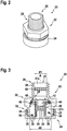
- Figure 2 depicts a perspective view of a drain valve 20 according to an exemplary embodiment of the invention
- Figure 3 shows a cross-sectional view thereof.
- the drain valve 20 shown in Figures 2 and 3 comprises a housing 22 including a first housing portion 23, which is shown in the upper parts of Figures 2 and 3 , and a second housing portion 24, which is depicted in the lower parts of Figures 2 and 3 .
- the first portion 23 is facing the enclosed space 14 of the exterior aircraft light unit 2 and the second portion 24 is facing towards the outer environment 17 of the exterior aircraft light unit 2 (cf. Figure 1A ).
- the first portion 23 of the housing 22 comprises a first part 26, which is shown in the upper parts of Figures 2 and 3 , and a second part 32, which is depicted in the lower parts of Figures 2 and 3 .
- the first part 26 is facing the enclosed space 14 of the exterior aircraft light unit 2, and is therefore in the following is called the “inner part” 26, while the second part 32 is facing to the outer environment 17 of the exterior aircraft light unit 2, and is therefore in the following called the “outer part” 32 of the first portion 23.
- the inner part 26 and the outer part 32 are formed cylindrically around a common central axis A, respectively.
- the inner part 26 is provided with an outer thread 28, which allows to screw the inner part 26 into a matching inner thread (not shown) formed within the opening 18 of the housing 12 of the exterior aircraft light unit 2, in order to securely attach the drain valve 20 to the light unit 2.
- the outer periphery of the intermediate part 30 has the form of a hexagon screw. This allows screwing the upper portion 23 conveniently into the side wall 16 of the exterior aircraft light unit 2, using a conventional wrench.
- the outer part 32 is provided with an outer thread 34
- the second portion 24 of the housing 20 is provided with a matching inner thread 25.
- the matching threads 25, 34 allow screwing the first and second portions 23, 24 together for forming the housing 22, as it is shown in Figures 2 and 3 .
- the first portion 23 is provided with an inner bore 27 extending along the central axis A.
- the bore 27 has a first diameter d1.
- the bore 27 has a second diameter d2, which is larger than the first diameter d1 (d2>d1).
- the bore 27 is tapered, widening from the first diameter d1 to the second diameter d2.
- the second portion 24 comprises a bottom plate 35 closing the outer opening of the bore 27, when the first and second portions 23, 24 of the housing 22 are screwed together, as it is shown in Figures 2 and 3 .
- a plurality of openings 36, 28 are formed in the bottom plate 35, providing a plurality of flow paths between the bore 27 and the outer environment 17.
- a central opening 38 extending along the central axis A, is formed in a central part of the bottom plate 35.
- a cylindrical spring 40 which extends coaxially with the axis A, is mounted to said protrusion 34. At its opposite end facing away from the bottom plate 35, the cylindrical spring 40 elastically supports a movable plunger 42. The movable plunger 42 is movable along the axis A against the elastic force of the cylindrical spring 40.
- the plunger 42 has rotational symmetry with respect to the axis A and comprises a central bore or duct 44, extending along said axis A.
- a sealing ring 46 in particular an O-ring 46, is arranged along the circular outer periphery of the plunger 42.
- the cylindrical spring 40 urges the plunger 42 towards the inner part 26 of the first portion 23 of the housing 22, pressing the sealing ring 46 against the tapered portion 29 of the bore 27.
- the sealing ring 46 seals the interface between the plunger 42 and the inner wall of the tapered portion 29 of the bore 27, so that no fluid is able to pass between the outer periphery of the plunger 42 and the inner wall of the bore 27.
- a semi-permeable medium / membrane 48 in particular a GORETEX®-membrane, is attached to the side of the plunger 42 facing the inner part 26 of the first portion 23.
- the semi-permeable membrane 48 in particular covers and seals the central duct 44 formed within the plunger 42.
- the semi-permeable membrane 48 may be glued to the plunger 42, or it may be fixed to the plunger by other appropriate fixing means.
- the semi-permeable membrane 48 In case a pressure difference between the two sides of the semi-permeable membrane 48 exceeds a predetermined threshold, the semi-permeable membrane 48 is permeable for air and water vapor, but it is not permeable for liquids, in particular liquid water.
- Liquid water is not able to pass the semi-permeable membrane 48. Thus, liquid water cannot enter from the exterior into the enclosed space 14 of the exterior aircraft light unit 2 via the drain valve 20.
- liquid water in particular condensed water formed within the enclosed space 14 of the exterior aircraft light unit 2 collects on the semi-permeable membrane 48, said liquid water blocks the semi-permeable membrane 48, and the semi-permeable membrane 48 becomes non-permeable to air and water vapor as well.
- the elastic force of the cylindrical spring 40 forces the plunger 42 back into its closed position.
- the sealing ring 46 abuts against the tapered wall portion 29, sealing the drain valve 20 and allowing only air and water vapor to pass the drain valve 20 via the semi-permeable membrane 48, as it has been described before.
- a metal material 58 in particular metal wool, comprising a passivated and/or corrosion-resistant metal, may be provided in the bore 27.
- the metal material 58 in particular may be provided in the portion 27b of the bore 27 formed within the outer part 32 of the first portion 23.
- Said metal material 58 is configured for cooling hot gases flowing through the drain valve 20.
- Such hot gases may be generated for example when, e.g. due to a malfunction, fuel enters into the enclosed space 14 and is lighted there by the hot light sources 6. Cooling the hot gases flowing / blowing out of the exterior aircraft light unit 2 reduces the risk of lighting even more fuel gases, which may be present outside the light unit 2. As a result, the risk of a severe explosion of fuel gases is considerably reduced.
- a silica material 60 may be arranged on the side of the plunger 42 facing the enclosed space 14. Silica material absorbs moisture and thus helps to reduce the humidity within the enclosed space 14. Additionally or alternatively, silica material 60 may be arranged within the enclosed space 14 outside the drain valve 20.
- FIGS 4 and 5 illustrate a drain valve 20 according to another exemplary embodiment of the invention.
- Figure 4 shows a perspective view of the drain valve 20 and Figure 5 shows a cross-sectional view thereof.
- the first portion 23 of the housing 22 comprises a first (inner) cylindrical part 26 and a second (outer) cylindrical part 32, which has a larger diameter than the first part 26.
- the inner and outer cylindrical parts 26, 32 are formed coaxially with respect to a common axis A.
- An intermediate part 30 extends between the inner and outer cylindrical parts 26, 32 in a direction which is basically orthogonal to the axis A.
- the second portion 24 of the housing has the form of a bottom plate 35, which is attached to the front side of the first portion 23 shown at the bottom of Figures 4 and 5 .
- the first and second portions 23, 24 of the housing 22 may be attached to each other by gluing, press-fitting, welding or a similar suitable attaching method.
- the plunger 42 is supported by a pin 52 extending along the axis A through the inner part 26 of the first portion 23.
- the plunger 42 is fixed, e.g. screwed, glued or welded, to one end of the pin 52. Alternatively, it may be formed integrally with the pin 52.
- An opposing end of the pin 52 is supported on the inner part 26 of the first portion 23 by an elastic element 54, in particular an elastic cap 54, which is arranged at the upper side of the inner part 26.
- the cap 54 is provided with openings 56 allowing fluid to pass through the cap 54.
- the elastic element / cap 54 may deform elastically allowing the pin 52 and the plunger 42, which is attached to said pin 52, to move along the axis A.
- the elastic element 54 urges the pin 52 and the plunger 42 into a closed position, in which it closes the gap between the plunger 42 and the intermediate portion 30 of the housing 22, as it is illustrated in Figures 4 and 5 .
- the closed gap is sealed by a sealing ring 46, in particular an O-ring, which is arranged along the outer periphery of the plunger 42.
- two bores 44 are formed in the plunger 42 fluidly connecting the two sides of the plunger 42 facing the first and second portions 23, 24 of the housing 22, respectively.
- the skilled person will understand that the number and the size of the bores 44 is only exemplary and may be adjusted to the respective needs.
- a semi-permeable membrane 48, sealing the bores 44, is attached to the plunger 42, in particular to the side of the plunger 42 facing the second portion 24 of the housing 22.
- the semi-permeable membrane 48 also may be attached to the other side of the plunger 42 facing the first portion 23 of the housing 22.
- the functionality of the semi-permeable membrane 48 is identical with the functionality of the semi-permeable membrane 48 in the exemplary embodiment shown in Figures 2 and 3 .
- the semi-permeable membrane 48 is non-permeable to liquid water, but permeable to air and water vapor (in case a predetermined pressure difference is exceeded) so that air and water vapor may pass the semi-permeable membrane 48 for pressure compensation.
- a metal material 58 in particular metal wool, comprising a passivated and/or corrosion-resistant metal, may be provided in the bore 27.
- the metal material 58 in particular may be provided in the portion 27b of the bore 27 formed within the outer part 32 of the first portion 23.
- Said metal material 58 is configured for cooling hot gases flowing through the drain valve 20. Such hot gases may be generated e.g. when, due to a malfunction, fuel enters into the enclosed space 14 and is lighted there by the hot light sources 6. Cooling the hot gases flowing / blowing out of the exterior aircraft light unit 2 reduces the risk of lighting even more fuel gases, which may be present outside the light unit 2. As a result, the risk of a severe explosion of fuel gases is considerably reduced.
- a restricting structure 50 may be formed within the second portion 24 of the housing 22, in particular at the inner wall of the second portion 24. Said restricting structure 50 is configured to restrict the movement of the plunger 42 towards the bottom plate 35. It in particular avoids that the plunger 42 hits the bottom plate 35 even in case a large force is acting on the plunger 42. Such large forces e.g. may be generated when fuels are lighted within the enclosed space 14.
Landscapes
- Engineering & Computer Science (AREA)
- General Engineering & Computer Science (AREA)
- Mechanical Engineering (AREA)
- Aviation & Aerospace Engineering (AREA)
- Fluid-Driven Valves (AREA)
- Self-Closing Valves And Venting Or Aerating Valves (AREA)
- Check Valves (AREA)
- Arrangement Of Elements, Cooling, Sealing, Or The Like Of Lighting Devices (AREA)
Abstract
Description
- The present invention relates to a drain valve, in particular to a drain valve which may be employed in an exterior aircraft light unit and/or in a power supply box for an exterior aircraft light unit. The invention further relates to an exterior aircraft light unit and a power supply box for an exterior aircraft light unit with such a drain valve.
- Almost all aircraft are equipped with exterior aircraft light units. In particular, large passenger air planes are provided with a wide variety of exterior lights. Examples of such lights include navigation or position lights, beacon lights, anti-collision lights or strobe lights, wing lights, taxi lights, landing lights, runway turnoff lights, etc. All of these lights are respectively provided with at least one light source.
- Since the air pressure varies with the height over sea level, exterior aircraft light units need to be vented during flight in order to avoid that an excessive under- and/or overpressure forms within the exterior aircraft light unit during the ascent or descent of the aircraft, respectively. Venting results in an exchange of air between the interior of the exterior aircraft light unit and the environment. Due to temperature differences, water vapor comprised in air flowing into the exterior aircraft light unit may condense within the exterior aircraft light unit. An excessive amount of water inside the light unit deteriorates its functionality.
- It therefore would be beneficial to provide a drain valve which allows effective venting and draining of an exterior aircraft light unit.
- Exemplary embodiments of the invention include a drain valve for draining liquid, in particular water, from an enclosed space, such as the interior of an exterior aircraft light unit. According to an exemplary embodiment, the drain valve comprises a movable plunger, which is movable between a closed position and at least one open position, and an elastic element, which is configured to urge the movable plunger into its closed position. When positioned in its closed position, the plunger does not allow liquid to flow through the drain valve. When positioned in an open position, the plunger allows liquid to flow through the drain valve.
- The plunger is provided with at least one duct extending through the plunger and allowing fluid to flow through the plunger and the drain valve when the plunger is positioned in its closed position. Said at least one duct is sealed by a semi-permeable medium, which is permeable for air and water vapor in case a predetermined pressure difference is exceeded, and which is impermeable for liquid water even if the predetermined pressure difference is exceeded. Thus, only air and water vapor, but no liquid water may flow through the duct and pass the drain valve when the plunger is positioned in its closed position.
- Exemplary embodiments of the invention further include an exterior aircraft light unit comprising a housing which provides an enclosed space; at least one light source, which is arranged within the housing; a mounting portion, which is configured for mounting the housing to an aircraft; and a drain valve according to an exemplary embodiment of the invention. The drain valve is arranged at the housing in a flow path fluidly connecting the enclosed space with the outer environment and it is configured to alternately seal and vent the enclosed space.
- Exemplary embodiments of the invention also include a power supply box, in particular a power supply box configured for supplying power to an aircraft light unit. The power supply box comprises a housing providing an enclosed space; and a drain valve according to an exemplary embodiment of the invention. The drain valve is arranged at the housing in a flow path fluidly connecting the enclosed space with the outer environment and it is configured to alternately seal and vent the enclosed space
- Exemplary embodiments of the invention also include a drain valve configured to allow liquid water to pass therethrough in one direction while preventing liquid water from passing therethrough in a second direction, the second direction being opposite to the first direction, while allowing air and water vapor to pass therethrough in both the first direction and in the second direction.
- A drain valve according to an exemplary embodiment of the invention allows venting an enclosed space, in particular the enclosed space of an exterior aircraft light unit or of a power supply box, as air and water vapor may pass the semi-permeable membrane. The water blocking properties of the semi-permeable membrane, however, prevent liquid water from entering into the enclosed space. In case condensed liquid water collects within the enclosed space contacting the semi-permeable membrane, any flow through the semi-permeable membrane is blocked, i.e. even air and water vapor are not able to pass the semi-permeable membrane. When the semi-permeable membrane is blocked, an overpressure within the enclosed space moves the plunger into an open position allowing the liquid water to spill out of the enclosed space. As soon as the pressure has (nearly) equalized, the elastic element urges the plunger back into its closed position sealing the valve and preventing any liquid from entering the enclosed space.
- As a result, a drain valve according to an exemplary embodiment of the invention provides a reliable and cost effective solution to the task of venting and draining an exterior light unit and/or a power supply box of an aircraft. A drain valve according to an exemplary embodiment of the invention in particular operates autonomously without a need for external control.
- The expression of the drain valve being configured to alternately seal and vent the enclosed space means that the drain valve may seal the enclosed space from liquids, in particular from water entering or leaving the enclosed space at some points in time, while a liquid path between the enclosed space and the outside environment is provided at other points in time, namely when the plunger is in an open position. Alternately sealing and venting the enclosed space means that both the state of sealing and the state of venting / draining can be provided by the drain valve at different points in time.
- The drain valve provides two paths between the enclosed space and the outside environment, namely a first path along the plunger, which is open or closed, depending on the position of the plunger, and a second path through the at least one duct and through the semi-permeable medium, which is open for air and water vapor, but closed for liquids, in particular water. In other words, the second path is closed for some kinds of fluids, such as water, while being open for other kinds of fluids, such as air and water vapor. As discussed above, the permeability for those other kinds of fluids may be compromised by water build-up at the semi-permeable medium in operation.
- In an embodiment, the elastic element is a coil spring. A coil spring provides a reliable elastic element, which may be produced at low costs.
- In an embodiment, the elastic element is an elastic support, in particular an elastic cover, supporting the plunger. Providing the elastic element as an elastic support, in particular as an elastic cover, allows for a very compact and efficient configuration of the drain valve.
- In an embodiment, the drain valve comprises a sealing ring, in particular an O-ring, which is configured for sealing the drain valve when the plunger is arranged in its closed position. A sealing ring, in particular an O-ring, provides a very reliable and efficient sealing element at low costs.
- In an embodiment, the semi-permeable medium is a semi-permeable membrane. The semi-permeable membrane in particular is attached to one face of the plunger. Providing the semi-permeable medium as a semi-permeable membrane provides a large semi-permeable surface using only a relatively small amount of material. The semi-permeable membrane in particular may be a GORETEX®-membrane, which is a very efficient and reliable semi-permeable membrane.
- In an embodiment, the drain valve comprises a first housing portion and a second housing portion. The first and second housing portions may comprise matching threads, which allow to screw the first and second housing portions together for forming a housing of the drain valve. Such a configuration provides a housing which is easy to install and which provides easy access to the inside of the drain valve for maintenance and/or repair.
- In an embodiment, the housing, in particular the portions of the housing, may be made from metal or plastic. Metal provides a very robust housing. A housing made of plastic may have a low weight and may be produced at low costs.
- In an embodiment, the housing may have an attachment thread for screwing the drain valve into the housing of the exterior aircraft light unit or into the housing of the power supply box. The attachment thread may be an external thread coupleable to an internal thread of the housing of the exterior aircraft light unit or of the housing of the power supply box. The attachment thread may be standardized. This may allow using one kind of drain valves for various kinds of exterior aircraft light units and/or power supply boxes.
- In an embodiment, the drain valve further comprises silica material, which in particular is arranged on the side of the plunger facing the enclosed space. Silica material absorbs moisture and thus helps to reduce the humidity within the enclosed space.
- In an embodiment, the drain valve comprises a metallic material, in particular metal wool, which is arranged in the flow path between the enclosed space and the environment.
- A metallic material, such as metal wool, in particular a material comprising a passivated and/or corrosion-resistant metal, is able to cool hot gases flowing through the drain valve. Such hot gases may be generated for example if, e.g. due to a malfunction, fuel flows into the enclosed space and is lighted by hot light sources. Cooling hot gases flowing out of the exterior aircraft light unit reduces the risk of lighting further fuel gases outside the light unit. As a result, the risk of a severe explosion caused by lighted fuel is considerably reduced.
- In an embodiment, the drain valve comprises a stop or a restricting structure, which is configured for restricting the movement of the plunger into an open position. Said restricting structure is configured to restrict the movement of the plunger in particular in case a large force is acting on the plunger. Such large forces e.g. may be generated when fuel is lighted within the enclosed space. A restricting structure avoids an uncontrolled / unrestricted movement of the plunger and thus enhances the safety of the exterior aircraft light unit.
- Exemplary embodiments of the invention are described in greater detail below with reference to the enclosed figures.
-
Figure 1A depicts a schematic sectional view of an exterior aircraft light unit with a drain valve according to an exemplary embodiment of the invention. -
Figure 1B depicts a schematic sectional view of a power supply box with a drain valve according to an exemplary embodiment of the invention. -
Figure 2 depicts a perspective view of a drain valve according to an exemplary embodiment of the invention. -
Figure 3 shows a cross-sectional view of the drain valve depicted inFigure 2 . -
Figure 4 depicts a perspective view of a drain valve according to another exemplary embodiment of the invention. -
Figure 5 shows a cross-sectional view of the drain valve depicted inFigure 4 . -
Figure 1A depicts a schematic sectional view of an exterior aircraftlight unit 2 with adrain valve 20 according to an exemplary embodiment of the invention. - The exterior aircraft
light unit 2 shown inFigure 1A comprises ahousing 12. At least one side of thehousing 12 is provided as a transparentexternal cover 10. The transparentexternal cover 10 may be formed as a lens and thus may also be referred to as lens cover 10. Astructural wall 8 supporting a light source 4 is arranged opposite to the transparentexternal cover 10, defining anenclosed space 14 between the transparentexternal cover 10 and thestructural wall 8. An electric control circuit, which is configured for controlling the operation of the light source 4, is arranged on a rear side of thestructural wall 8 facing away from the enclosedspace 14. Arear side wall 13 of thehousing 12 opposite to the transparentexternal cover 10 is formed as or provided with at least one mountingportion 15. The mountingportion 15 is configured for mounting the exterior aircraftlight unit 2 to an aircraft (not shown), such as an airplane or helicopter. The exterior aircraftlight unit 2 in particular may be mounted to the fuselage, to a wing or to a gear of the aircraft. - In the exemplary embodiment shown in
Figure 1A , the light source 4 is provided as a light source arrangement comprising a plurality oflight emitting elements 6 arranged next to each other. In an alternative exemplary embodiment, which is not shown in the figures, the light source 4 may comprise only a singlelight emitting element 6. - The
light emitting elements 6 may be arranged as a one-dimensional strip, as a two-dimensional array/matrix structure, or in any other pattern which is suitable for generating the desired light emission. Thelight emitting elements 6 may be embodied as LEDs, providing highly efficientlight emitting elements 6. Depending on the function of the exterior aircraftlight unit 2, thelight emitting elements 6 may be configured for emitting light of the same color, or they may be configured for emitting light of different colors. - An
opening 18 providing a flow passage between theenclosed space 14 and theouter environment 17 of the exterior aircraftlight unit 2 is formed in aside wall 16 of thehousing 12, extending between the transparentexternal cover 10 and thestructural wall 8. - A
drain valve 20 according to an exemplary embodiment of the invention is arranged within saidopening 18. Thedrain valve 20 comprises afirst portion 23, facing the enclosedspace 14 formed within thehousing 12, and asecond portion 24, facing theouter environment 17 of thehousing 12 / exterior aircraftlight unit 2. - The
drain valve 20 is configured to allow gas, in particular air and water vapor, to flow into and out of the enclosedspace 14 via thedrain valve 20. This allows to compensate pressure differences between theenclosed space 14 and theouter environment 17. - The
drain valve 20 is further configured to block liquid water from entering into the enclosedspace 14 from theouter environment 17, but to allow liquid water, in particular condensed water which has formed within the enclosedspace 14, to flow out of the enclosedspace 14. - Although only a
single opening 18 with asingle drain valve 20 is shown inFigure 1A , the skilled person will understand that a plurality ofdrain valves 20 may be provided in a plurality ofopenings 18 in order to increase the venting / draining capacity of the exterior aircraftlight unit 2. -
Figure 1B schematically depicts apower supply box 3 including adrain valve 20 according to an exemplary embodiment of the invention. - The
power supply box 3 comprises ahousing 12 accommodating at least oneelectric control circuit 31, which is configured for supplying electrical power to an exterior aircraftlight unit 2, e.g. an exterior aircraftlight unit 2 as depicted inFigure 1A . Thepower supply box 3 has apower input 61, which is coupled to an aircraft on-board power supply network, when arranged in an aircraft, and apower output 62, which is coupled to and provides controlled power to an exterior aircraft light unit, when arranged in an aircraft. - At least one
side 13 of thehousing 12 is formed as or provided with at least one mountingportion 15, which is configured for mounting thepower supply box 3 to the aircraft, such as an airplane or helicopter. - An
opening 18, providing a flow passage between theenclosed space 14 and theouter environment 17 of thepower supply box 3, is formed in aside wall 16 of thehousing 12. - A
drain valve 20 according to an exemplary embodiment of the invention is arranged within saidopening 18. Thedrain valve 20 comprises afirst portion 23, facing the enclosedspace 14 formed within thehousing 12, and asecond portion 24, facing theouter environment 17 of thehousing 12 /power supply box 3. - The
drain valve 20 is configured to allow air and water vapor to flow into and out of the enclosedspace 14 via thedrain valve 20 in order to allow for the compensation of pressure differences between theenclosed space 14 and theouter environment 17. - The
drain valve 20 is further configured to block liquid water from entering into the enclosedspace 14 from theouter environment 17, but to allow liquid water, in particular condensed water which has formed within the enclosedspace 14, to flow out of the enclosedspace 14. - Although only a
single opening 18 with asingle drain valve 20 is shown inFigure 1B , the skilled person will understand that a plurality ofdrain valves 20 may be provided in a plurality ofopenings 18 in order to increase the venting / draining capacity. - In the following, exemplary embodiments of the
drain valve 20 will be discussed in more detail with reference toFigures 2 to 5 . -
Figure 2 depicts a perspective view of adrain valve 20 according to an exemplary embodiment of the invention, andFigure 3 shows a cross-sectional view thereof. - The
drain valve 20 shown inFigures 2 and 3 comprises ahousing 22 including afirst housing portion 23, which is shown in the upper parts ofFigures 2 and 3 , and asecond housing portion 24, which is depicted in the lower parts ofFigures 2 and 3 . - When the
drain valve 20 is installed within thehousing 12 of the exterior aircraftlight unit 2, thefirst portion 23 is facing the enclosedspace 14 of the exterior aircraftlight unit 2 and thesecond portion 24 is facing towards theouter environment 17 of the exterior aircraft light unit 2 (cf.Figure 1A ). - The
first portion 23 of thehousing 22 comprises afirst part 26, which is shown in the upper parts ofFigures 2 and 3 , and asecond part 32, which is depicted in the lower parts ofFigures 2 and 3 . - When the
drain valve 20 is installed within thehousing 12 of the exterior aircraftlight unit 2, thefirst part 26 is facing the enclosedspace 14 of the exterior aircraftlight unit 2, and is therefore in the following is called the "inner part" 26, while thesecond part 32 is facing to theouter environment 17 of the exterior aircraftlight unit 2, and is therefore in the following called the "outer part" 32 of thefirst portion 23. Athird part 30 of thefirst portion 23, which is arranged between the first andsecond parts - The
inner part 26 and theouter part 32 are formed cylindrically around a common central axis A, respectively. - The
inner part 26 is provided with anouter thread 28, which allows to screw theinner part 26 into a matching inner thread (not shown) formed within theopening 18 of thehousing 12 of the exterior aircraftlight unit 2, in order to securely attach thedrain valve 20 to thelight unit 2. - The outer periphery of the
intermediate part 30 has the form of a hexagon screw. This allows screwing theupper portion 23 conveniently into theside wall 16 of the exterior aircraftlight unit 2, using a conventional wrench. - The
outer part 32 is provided with anouter thread 34, and thesecond portion 24 of thehousing 20 is provided with a matchinginner thread 25. The matchingthreads second portions housing 22, as it is shown inFigures 2 and 3 . - The
first portion 23 is provided with aninner bore 27 extending along the central axis A. In theinner part 26, thebore 27 has a first diameter d1. In theouter part 32, thebore 27 has a second diameter d2, which is larger than the first diameter d1 (d2>d1). In theintermediate part 30, thebore 27 is tapered, widening from the first diameter d1 to the second diameter d2. - The
second portion 24 comprises abottom plate 35 closing the outer opening of thebore 27, when the first andsecond portions housing 22 are screwed together, as it is shown inFigures 2 and 3 . A plurality ofopenings bottom plate 35, providing a plurality of flow paths between thebore 27 and theouter environment 17. - A
central opening 38, extending along the central axis A, is formed in a central part of thebottom plate 35. Acylindrical protrusion 34, surrounding thecentral opening 38, extends from thebottom plate 35 towards thefirst portion 23. - A
cylindrical spring 40, which extends coaxially with the axis A, is mounted to saidprotrusion 34. At its opposite end facing away from thebottom plate 35, thecylindrical spring 40 elastically supports amovable plunger 42. Themovable plunger 42 is movable along the axis A against the elastic force of thecylindrical spring 40. - The
plunger 42 has rotational symmetry with respect to the axis A and comprises a central bore orduct 44, extending along said axis A. A sealingring 46, in particular an O-ring 46, is arranged along the circular outer periphery of theplunger 42. - In an idle state, i.e. in a state in which no external force is acting on the
plunger 42, thecylindrical spring 40 urges theplunger 42 towards theinner part 26 of thefirst portion 23 of thehousing 22, pressing the sealingring 46 against the taperedportion 29 of thebore 27. As a result, the sealingring 46 seals the interface between theplunger 42 and the inner wall of the taperedportion 29 of thebore 27, so that no fluid is able to pass between the outer periphery of theplunger 42 and the inner wall of thebore 27. - A semi-permeable medium /
membrane 48, in particular a GORETEX®-membrane, is attached to the side of theplunger 42 facing theinner part 26 of thefirst portion 23. Thesemi-permeable membrane 48 in particular covers and seals thecentral duct 44 formed within theplunger 42. Thesemi-permeable membrane 48 may be glued to theplunger 42, or it may be fixed to the plunger by other appropriate fixing means. - In case a pressure difference between the two sides of the
semi-permeable membrane 48 exceeds a predetermined threshold, thesemi-permeable membrane 48 is permeable for air and water vapor, but it is not permeable for liquids, in particular liquid water. - In consequence, in case there is a pressure difference between the
portion 27a of thebore 27 formed within theinner part 26 of thefirst portion 23, which is fluidly connected with theenclosed space 14 of the exterior aircraft light unit 2 (cf.Figure 1A ), and theportion 27b of thebore 27 formed within theouter part 32 of thefirst portion 23, air and water vapor may pass through thesemi-permeable membrane 48 and flow through thecentral duct 44 formed within theplunger 42 and the central opening 38 (and the additional openings 36) formed within thebottom plate 35 of thesecond portion 24 of thehousing 22, or in the opposite direction, in order to compensate for said pressure difference. - Liquid water, however, is not able to pass the
semi-permeable membrane 48. Thus, liquid water cannot enter from the exterior into the enclosedspace 14 of the exterior aircraftlight unit 2 via thedrain valve 20. - If liquid water, in particular condensed water formed within the enclosed
space 14 of the exterior aircraftlight unit 2, collects on thesemi-permeable membrane 48, said liquid water blocks thesemi-permeable membrane 48, and thesemi-permeable membrane 48 becomes non-permeable to air and water vapor as well. - In this case, a sufficient increase of the pressure within the
portion 27a of thebore 27 formed within theinner part 26 of thefirst portion 23, which is fluidly connected with theenclosed space 14 of the exterior aircraft light unit 2 (cf.Figure 1A ), causes theplunger 42 to move towards thebottom plate 35 compressing thecylindrical spring 40. - This movement of the
plunger 42 creates a gap between the sealingring 46 and the taperedwall portion 29 of thebore 27. Liquid water collected on theplunger 42 will flow through said gap from theinner part 26 through theintermediate part 30 into theouter part 32 and exit thedrain valve 20 via theopenings 36 formed in thebottom plate 35. - After the liquid water has been drained and the pressure within the
upper portion 26 has been reduced, the elastic force of thecylindrical spring 40 forces theplunger 42 back into its closed position. When theplunger 42 is in its closed position, the sealingring 46 abuts against the taperedwall portion 29, sealing thedrain valve 20 and allowing only air and water vapor to pass thedrain valve 20 via thesemi-permeable membrane 48, as it has been described before. - A
metal material 58, in particular metal wool, comprising a passivated and/or corrosion-resistant metal, may be provided in thebore 27. Themetal material 58 in particular may be provided in theportion 27b of thebore 27 formed within theouter part 32 of thefirst portion 23. Saidmetal material 58 is configured for cooling hot gases flowing through thedrain valve 20. Such hot gases may be generated for example when, e.g. due to a malfunction, fuel enters into the enclosedspace 14 and is lighted there by thehot light sources 6. Cooling the hot gases flowing / blowing out of the exterior aircraftlight unit 2 reduces the risk of lighting even more fuel gases, which may be present outside thelight unit 2. As a result, the risk of a severe explosion of fuel gases is considerably reduced. - A
silica material 60 may be arranged on the side of theplunger 42 facing the enclosedspace 14. Silica material absorbs moisture and thus helps to reduce the humidity within the enclosedspace 14. Additionally or alternatively,silica material 60 may be arranged within the enclosedspace 14 outside thedrain valve 20. -
Figures 4 and 5 illustrate adrain valve 20 according to another exemplary embodiment of the invention. -
Figure 4 shows a perspective view of thedrain valve 20 andFigure 5 shows a cross-sectional view thereof. - The elements of the
drain valve 20 which correspond with the elements of the exemplary embodiment shown inFigures 2 and 3 are denoted with the same reference signs and will not be discussed in detail again. - In the exemplary embodiment shown in
Figures 4 and 5 , thefirst portion 23 of thehousing 22 comprises a first (inner)cylindrical part 26 and a second (outer)cylindrical part 32, which has a larger diameter than thefirst part 26. The inner and outercylindrical parts intermediate part 30 extends between the inner and outercylindrical parts - The
second portion 24 of the housing has the form of abottom plate 35, which is attached to the front side of thefirst portion 23 shown at the bottom ofFigures 4 and 5 . The first andsecond portions housing 22 may be attached to each other by gluing, press-fitting, welding or a similar suitable attaching method. - The
plunger 42 is supported by apin 52 extending along the axis A through theinner part 26 of thefirst portion 23. Theplunger 42 is fixed, e.g. screwed, glued or welded, to one end of thepin 52. Alternatively, it may be formed integrally with thepin 52. - An opposing end of the
pin 52 is supported on theinner part 26 of thefirst portion 23 by anelastic element 54, in particular anelastic cap 54, which is arranged at the upper side of theinner part 26. - The
cap 54 is provided withopenings 56 allowing fluid to pass through thecap 54. - The elastic element /
cap 54 may deform elastically allowing thepin 52 and theplunger 42, which is attached to saidpin 52, to move along the axis A. - In an idle state, i.e. when no external force is acting on the
plunger 42, theelastic element 54 urges thepin 52 and theplunger 42 into a closed position, in which it closes the gap between theplunger 42 and theintermediate portion 30 of thehousing 22, as it is illustrated inFigures 4 and 5 . The closed gap is sealed by a sealingring 46, in particular an O-ring, which is arranged along the outer periphery of theplunger 42. - In the exemplary embodiment shown in
Figures 4 and 5 , twobores 44 are formed in theplunger 42 fluidly connecting the two sides of theplunger 42 facing the first andsecond portions housing 22, respectively. The skilled person will understand that the number and the size of thebores 44 is only exemplary and may be adjusted to the respective needs. - A
semi-permeable membrane 48, sealing thebores 44, is attached to theplunger 42, in particular to the side of theplunger 42 facing thesecond portion 24 of thehousing 22. The skilled person, however, will understand that thesemi-permeable membrane 48 also may be attached to the other side of theplunger 42 facing thefirst portion 23 of thehousing 22. - The functionality of the
semi-permeable membrane 48 is identical with the functionality of thesemi-permeable membrane 48 in the exemplary embodiment shown inFigures 2 and 3 . I.e., thesemi-permeable membrane 48 is non-permeable to liquid water, but permeable to air and water vapor (in case a predetermined pressure difference is exceeded) so that air and water vapor may pass thesemi-permeable membrane 48 for pressure compensation. - However, in case liquid water, in particular condensed water, collects on the
semi-permeable membrane 48, the flow path through thesemi-permeable membrane 48 is blocked. In consequence, thesemi-permeable membrane 48 becomes impermeable to air and water vapor as well - As a result, an overpressure in the
portion 27a of thebore 27 formed within theinner part 26 of thefirst portion 23, which is fluidly connected with theenclosed space 14 of the exterior aircraft light unit 2 (cf.Figure 1A ), urges theplunger 42 towards thesecond portion 24, creating a gap between the sealingring 46 and theintermediate portion 30 of thehousing 22. Said gap allows liquid water collected on thesemi-permeable membrane 48 to pass through said gap and to flow out of thedrain valve 20 via theopenings 36 formed in thebottom plate 35 of thesecond portion 24. - When the pressure difference between the interior space within the
inner part 26 and the exterior has (nearly) equalized and no opening force is acting onto theplunger 42 anymore, the elastic force of theelastic cap 54 forces thepin 52 and theplunger 42 back into the closed position shown inFigure 5 , in which the sealingring 46 is pressed against theintermediate portion 30 of thehousing 22, sealing thedrain valve 20. - A
metal material 58, in particular metal wool, comprising a passivated and/or corrosion-resistant metal, may be provided in thebore 27. Themetal material 58 in particular may be provided in theportion 27b of thebore 27 formed within theouter part 32 of thefirst portion 23. Saidmetal material 58 is configured for cooling hot gases flowing through thedrain valve 20. Such hot gases may be generated e.g. when, due to a malfunction, fuel enters into the enclosedspace 14 and is lighted there by thehot light sources 6. Cooling the hot gases flowing / blowing out of the exterior aircraftlight unit 2 reduces the risk of lighting even more fuel gases, which may be present outside thelight unit 2. As a result, the risk of a severe explosion of fuel gases is considerably reduced. - A restricting structure 50 may be formed within the
second portion 24 of thehousing 22, in particular at the inner wall of thesecond portion 24. Said restricting structure 50 is configured to restrict the movement of theplunger 42 towards thebottom plate 35. It in particular avoids that theplunger 42 hits thebottom plate 35 even in case a large force is acting on theplunger 42. Such large forces e.g. may be generated when fuels are lighted within the enclosedspace 14. - While the invention has been described with reference to exemplary embodiments, it will be understood by those skilled in the art that various changes may be made and equivalents may be substituted for elements thereof without departing from the scope of the invention. In addition many modifications may be made to adopt a particular situation or material to the teachings of the invention without departing from the essential scope thereof. Therefore, it is intended that the invention not be limited to the particular embodiment disclosed, but that the invention include all embodiments falling within the scope of the following claims.
Claims (14)
- Drain valve (20) for draining liquid from an enclosed space (14), the drain valve (20) comprising:a plunger (42), which is movable between a closed position in which the plunger (42) does not allow liquid to flow through the drain valve (20), and at least one open position, in which the plunger (42) allows liquid to flow through the drain valve (20); andan elastic element (40; 54), which is configured to urge the movable plunger (42) into its closed position;wherein the plunger (42) is provided with at least one duct (44) extending through the plunger (42) and allowing fluid to flow through the drain valve (20) when the plunger (42) is positioned in its closed position, and wherein said at least one duct (44) is closed by a semi-permeable medium (42), which is permeable for air and water vapor and impermeable for liquid water.
- Drain valve (20) according to claim 1, wherein the elastic element (40; 54) is a coil spring (40)
- Drain valve (20) according to claim 1, wherein the elastic element (54) is an elastic support, in particular an elastic cover (54), supporting the plunger (42).
- Drain valve (20) according to any of the previous claims, further comprising a sealing ring (46), in particular an O-ring, which is configured for sealing the drain valve (20) when the plunger (42) is arranged in its closed position.
- Drain valve (20) according to any of the previous claims, wherein the semi-permeable medium (48) is a semi-permeable membrane (48), wherein the semi-permeable membrane (48) in particular is attached to one face of the plunger (42).
- Drain valve (20) according to any of the previous claims, comprising a first housing portion (23) and a second housing portion (24), wherein the first and second housing portions (23, 24) in particular comprise matching threads which allow screwing the first and second housing portions (23, 24) together for forming a housing (22) of the drain valve (20).
- Drain valve (20) according to any of the previous claims comprising a housing (22) which is made from metal or plastic.
- Drain valve (20) according to any of the previous claims, further comprising silica material (60).
- Drain valve (20) according to any of the previous claims, further comprising a metallic material (58), in particular metal wool.
- Drain valve (20) according to any of the previous claims, further comprising a restricting structure (50) which is configured for restricting the movement of the plunger (42) when moving into an open position.
- Exterior aircraft light unit (2) comprising:a housing (12) providing an enclosed space (14);at least one light source (6), which is arranged within the housing (12);a mounting portion (15), which is configured for mounting the housing (12) to an aircraft; anda drain valve (20) according to one of the preceding claims;wherein the drain valve (20) is arranged at the housing (12) in a flow path fluidly connecting the enclosed space (14) with the outer environment and is configured to alternately seal and vent the enclosed space (14).
- Exterior aircraft light unit (2) according to claim 11, wherein the exterior aircraft light unit (2) is at least one of a position light unit, a beacon light unit, an anti-collision light unit, a strobe light unit, a wing light unit, a landing light unit, an awareness light unit, a runway turn-off light unit, a take-off light unit, a taxi light unit and a multi-functional light unit providing at least two of the functionalities of a position light unit, a beacon light unit, an anti-collision light unit, a strobe light unit, a wing light unit, a landing light unit, an awareness light unit, a runway turn-off light unit, a take-off light unit, and a taxi light unit.
- Power supply box (3), in particular a power supply box (3) which is configured for supplying power to an aircraft light unit (2), wherein the power supply box (3) comprises:a housing (12) providing an enclosed space (14); anda drain valve (20) according to one of the preceding claims which is arranged at the housing in a flow path fluidly connecting the enclosed space (14) with the outer environment which is configured to alternately seal and vent the enclosed space (14)
- Power supply box (3) configured for supplying power to an aircraft light unit (2), comprising a mounting portion (15), which is configured for mounting the power supply box (3) to an aircraft.
Priority Applications (5)
| Application Number | Priority Date | Filing Date | Title |
|---|---|---|---|
| EP17171905.7A EP3403934B1 (en) | 2017-05-19 | 2017-05-19 | Drain valve, exterior aircraft light unit and power supply box |
| CA3004732A CA3004732A1 (en) | 2017-05-19 | 2018-05-10 | Drain valve, exterior aircraft light unit and power supply box |
| BR102018009922-1A BR102018009922A2 (en) | 2017-05-19 | 2018-05-16 | ? drain valve, aircraft external lighting unit, and power supply box? |
| CN201810480908.5A CN108930824A (en) | 2017-05-19 | 2018-05-18 | Bleed valve, external aircraft light unit and power supply box |
| US15/983,130 US10941864B2 (en) | 2017-05-19 | 2018-05-18 | Drain valve, exterior aircraft light unit and power supply box |
Applications Claiming Priority (1)
| Application Number | Priority Date | Filing Date | Title |
|---|---|---|---|
| EP17171905.7A EP3403934B1 (en) | 2017-05-19 | 2017-05-19 | Drain valve, exterior aircraft light unit and power supply box |
Publications (2)
| Publication Number | Publication Date |
|---|---|
| EP3403934A1 true EP3403934A1 (en) | 2018-11-21 |
| EP3403934B1 EP3403934B1 (en) | 2021-01-27 |
Family
ID=58738940
Family Applications (1)
| Application Number | Title | Priority Date | Filing Date |
|---|---|---|---|
| EP17171905.7A Active EP3403934B1 (en) | 2017-05-19 | 2017-05-19 | Drain valve, exterior aircraft light unit and power supply box |
Country Status (5)
| Country | Link |
|---|---|
| US (1) | US10941864B2 (en) |
| EP (1) | EP3403934B1 (en) |
| CN (1) | CN108930824A (en) |
| BR (1) | BR102018009922A2 (en) |
| CA (1) | CA3004732A1 (en) |
Cited By (4)
| Publication number | Priority date | Publication date | Assignee | Title |
|---|---|---|---|---|
| GB2575733A (en) * | 2018-07-17 | 2020-01-22 | Motorola Solutions Inc | Automatic testable breather valve |
| CN111824435A (en) * | 2019-04-18 | 2020-10-27 | 古德里奇照明系统有限责任公司 | Aircraft beacon lights and aircraft including aircraft beacon lights |
| EP4491520A1 (en) * | 2023-07-05 | 2025-01-15 | Goodrich Lighting Systems, Inc. | Exterior lighting water removal valve |
| US12435857B2 (en) | 2023-05-11 | 2025-10-07 | Goodrich Lighting Systems GmbH & Co. KG | Exterior aircraft light, aircraft comprising an exterior aircraft light and method of draining a fluid out of an exterior aircraft light |
Families Citing this family (5)
| Publication number | Priority date | Publication date | Assignee | Title |
|---|---|---|---|---|
| EP4197916B1 (en) * | 2021-12-20 | 2025-06-18 | Goodrich Corporation | Magnetically controlled fluid drain valve for aircraft exterior light unit |
| US12270523B2 (en) | 2021-12-20 | 2025-04-08 | Goodrich Corporation | Magnetically controlled fluid drain valve for aircraft exterior light unit |
| FR3131951B1 (en) * | 2022-01-17 | 2024-03-22 | Aml Systems | Device for dehumidifying a closed enclosure |
| EP4477559B1 (en) * | 2023-06-13 | 2026-01-21 | Goodrich Lighting Systems GmbH & Co. KG | Exterior aircraft light, aircraft comprising an exterior aircraft light and method of draining a fluid out of an exterior aircraft light |
| US12031695B1 (en) | 2023-07-05 | 2024-07-09 | Goodrich Lighting Systems, Inc. | Exterior lighting water removal valve |
Citations (6)
| Publication number | Priority date | Publication date | Assignee | Title |
|---|---|---|---|---|
| AU7754075A (en) * | 1974-02-01 | 1976-07-22 | Balassa O | Check valve |
| US4809144A (en) * | 1986-12-11 | 1989-02-28 | Stanley Electric Co., Ltd. | Vehicle headlamp with a vent hole |
| WO2008105724A1 (en) * | 2007-02-27 | 2008-09-04 | Scania Cv Ab | Fuel tank vent assembly for a vehicle fuel tank and fuel tank equipped therewith |
| US20120048871A1 (en) * | 2010-08-30 | 2012-03-01 | Teh-Tsung Chiu | Waterproof and breathable plug |
| CN202203913U (en) * | 2011-07-27 | 2012-04-25 | 深圳市景瑞德科技有限公司 | LED (light-emitting diode) split waterproof breathable device |
| EP3168159A1 (en) * | 2015-11-13 | 2017-05-17 | Goodrich Lighting Systems GmbH | Exterior aircraft light unit |
Family Cites Families (19)
| Publication number | Priority date | Publication date | Assignee | Title |
|---|---|---|---|---|
| US2809144A (en) | 1955-01-27 | 1957-10-08 | Narmco Sporting Goods Company | Method of making a composite golf shaft for a golf club |
| US5775794A (en) | 1995-07-31 | 1998-07-07 | Textron Inc. | Headlamp adjustor with vent tube |
| US6210014B1 (en) | 1997-01-21 | 2001-04-03 | Gore Enterprise Holdings, Inc. | System for reducing condensation in enclosed lamp housings |
| US6071000A (en) * | 1998-09-25 | 2000-06-06 | Valeo Sylvania, L.L.C. | Vehicle lamp with ram air vent |
| US6709493B2 (en) | 2001-03-26 | 2004-03-23 | Gore Enterprise Holdings, Inc. | Device for reducing the presence of moisture within an enclosure containing a heat source |
| DE10359748A1 (en) * | 2003-12-19 | 2005-07-28 | Dr.Ing.H.C. F. Porsche Ag | Lighting equipment |
| US7217314B2 (en) | 2005-01-10 | 2007-05-15 | Gore Enterprise Holdings, Inc. | Venting system for minimizing condensation in a lighting assembly |
| US7927405B2 (en) | 2007-04-23 | 2011-04-19 | Gore Enterprise Holdings, Inc | Porous composite article |
| US20090268475A1 (en) * | 2008-04-24 | 2009-10-29 | Earl Ball | Ventilation system for lamp enclosures |
| US20100068431A1 (en) | 2008-09-17 | 2010-03-18 | Vishal Bansal | Article and method for forming an article |
| CN101761831A (en) * | 2010-01-20 | 2010-06-30 | 中山市盈点光电科技有限公司 | Angle-adjustable high-heat-dissipation LED module street lamp cap |
| DE202010001191U1 (en) * | 2010-01-20 | 2011-05-26 | REINZ-Dichtungs-GmbH, 89233 | Valve for controlling a gas flow, liquid separator, venting system and internal combustion engine with such a valve |
| CN104334406B (en) * | 2012-05-24 | 2017-08-11 | 三菱电机株式会社 | Dehydrating unit, vehicle-mounted light fixture and light source igniting device |
| US8911247B2 (en) | 2013-03-15 | 2014-12-16 | A.L.P. Lighting & Ceiling Products, Inc. | Quick connector system luminiary fitting |
| JP6803130B2 (en) * | 2014-11-19 | 2020-12-23 | 日東電工株式会社 | lamp |
| EP3460315A4 (en) * | 2016-05-16 | 2019-10-23 | Mitsubishi Electric Corporation | VEHICLE HEADLIGHT |
| DE102016119511A1 (en) * | 2016-10-13 | 2018-04-19 | Automotive Lighting Reutlingen Gmbh | Motor vehicle lighting device with a ventilation device |
| US20190271450A1 (en) * | 2018-03-05 | 2019-09-05 | GM Global Technology Operations LLC | Lamp assembly |
| EP3626629B1 (en) * | 2018-09-21 | 2021-07-21 | Goodrich Lighting Systems GmbH | Exterior aircraft light and aircraft comprising the same |
-
2017
- 2017-05-19 EP EP17171905.7A patent/EP3403934B1/en active Active
-
2018
- 2018-05-10 CA CA3004732A patent/CA3004732A1/en not_active Abandoned
- 2018-05-16 BR BR102018009922-1A patent/BR102018009922A2/en not_active Application Discontinuation
- 2018-05-18 CN CN201810480908.5A patent/CN108930824A/en active Pending
- 2018-05-18 US US15/983,130 patent/US10941864B2/en active Active
Patent Citations (6)
| Publication number | Priority date | Publication date | Assignee | Title |
|---|---|---|---|---|
| AU7754075A (en) * | 1974-02-01 | 1976-07-22 | Balassa O | Check valve |
| US4809144A (en) * | 1986-12-11 | 1989-02-28 | Stanley Electric Co., Ltd. | Vehicle headlamp with a vent hole |
| WO2008105724A1 (en) * | 2007-02-27 | 2008-09-04 | Scania Cv Ab | Fuel tank vent assembly for a vehicle fuel tank and fuel tank equipped therewith |
| US20120048871A1 (en) * | 2010-08-30 | 2012-03-01 | Teh-Tsung Chiu | Waterproof and breathable plug |
| CN202203913U (en) * | 2011-07-27 | 2012-04-25 | 深圳市景瑞德科技有限公司 | LED (light-emitting diode) split waterproof breathable device |
| EP3168159A1 (en) * | 2015-11-13 | 2017-05-17 | Goodrich Lighting Systems GmbH | Exterior aircraft light unit |
Cited By (6)
| Publication number | Priority date | Publication date | Assignee | Title |
|---|---|---|---|---|
| GB2575733A (en) * | 2018-07-17 | 2020-01-22 | Motorola Solutions Inc | Automatic testable breather valve |
| US10631422B2 (en) | 2018-07-17 | 2020-04-21 | Motorola Solutions, Inc. | Automatic testable breather valve |
| GB2575733B (en) * | 2018-07-17 | 2020-07-29 | Motorola Solutions Inc | Automatic testable breather valve |
| CN111824435A (en) * | 2019-04-18 | 2020-10-27 | 古德里奇照明系统有限责任公司 | Aircraft beacon lights and aircraft including aircraft beacon lights |
| US12435857B2 (en) | 2023-05-11 | 2025-10-07 | Goodrich Lighting Systems GmbH & Co. KG | Exterior aircraft light, aircraft comprising an exterior aircraft light and method of draining a fluid out of an exterior aircraft light |
| EP4491520A1 (en) * | 2023-07-05 | 2025-01-15 | Goodrich Lighting Systems, Inc. | Exterior lighting water removal valve |
Also Published As
| Publication number | Publication date |
|---|---|
| EP3403934B1 (en) | 2021-01-27 |
| BR102018009922A2 (en) | 2018-12-18 |
| CA3004732A1 (en) | 2018-11-19 |
| US10941864B2 (en) | 2021-03-09 |
| US20180335150A1 (en) | 2018-11-22 |
| CN108930824A (en) | 2018-12-04 |
Similar Documents
| Publication | Publication Date | Title |
|---|---|---|
| US10941864B2 (en) | Drain valve, exterior aircraft light unit and power supply box | |
| EP1394372B1 (en) | Combined shut-off valve and cover for an engine breather system | |
| US9254923B2 (en) | Aircraft fuel system and aircraft | |
| EP3421847B1 (en) | Safety bypass valve | |
| CN105422964B (en) | A kind of fuel tank isolation valve | |
| CN105270608A (en) | Aircraft air scoop systems with passive pneumatic actuators | |
| KR20160005653A (en) | Add-on chamber for improved response of gas pressure regulators | |
| US10352209B2 (en) | Pressure regulator assemblies | |
| US4091895A (en) | Oil level sensing apparatus | |
| CN102563154A (en) | High-flow pressure loading type decompression valve | |
| US9285045B2 (en) | Aircraft fuel tank vent protector | |
| KR20220114440A (en) | Infrared LED aircraft warning lights | |
| US2843145A (en) | Valve mechanism | |
| CN1489538A (en) | Vacuum protection with device to avoid accidental effects | |
| CN103939650B (en) | A kind of large flow constant flow valve that has overpressure protection function | |
| US9541216B2 (en) | Externally fitted control device and hydraulic control module for an externally fitted control device | |
| EP4197916B1 (en) | Magnetically controlled fluid drain valve for aircraft exterior light unit | |
| CN103541783B (en) | aviation piston engine system | |
| US2641985A (en) | Combination pressure relief, vacuum relief, and dump valve | |
| KR101257713B1 (en) | Vent valve | |
| US20090120517A1 (en) | Self regulating valve to obtain low differential air pressure control | |
| EP4461653B1 (en) | Exterior aircraft light, aircraft comprising an exterior aircraft light and method of draining a fluid out of an exterior aircraft light | |
| US20080207110A1 (en) | Rear axle breather | |
| CN120444359A (en) | Variable damping shock absorber and motor vehicle | |
| CN109373033B (en) | Waterproof vent valve for helicopter fuel tank |
Legal Events
| Date | Code | Title | Description |
|---|---|---|---|
| PUAI | Public reference made under article 153(3) epc to a published international application that has entered the european phase |
Free format text: ORIGINAL CODE: 0009012 |
|
| STAA | Information on the status of an ep patent application or granted ep patent |
Free format text: STATUS: THE APPLICATION HAS BEEN PUBLISHED |
|
| AK | Designated contracting states |
Kind code of ref document: A1 Designated state(s): AL AT BE BG CH CY CZ DE DK EE ES FI FR GB GR HR HU IE IS IT LI LT LU LV MC MK MT NL NO PL PT RO RS SE SI SK SM TR |
|
| AX | Request for extension of the european patent |
Extension state: BA ME |
|
| STAA | Information on the status of an ep patent application or granted ep patent |
Free format text: STATUS: REQUEST FOR EXAMINATION WAS MADE |
|
| 17P | Request for examination filed |
Effective date: 20190516 |
|
| RBV | Designated contracting states (corrected) |
Designated state(s): AL AT BE BG CH CY CZ DE DK EE ES FI FR GB GR HR HU IE IS IT LI LT LU LV MC MK MT NL NO PL PT RO RS SE SI SK SM TR |
|
| REG | Reference to a national code |
Ref country code: DE Ref legal event code: R079 Ref document number: 602017031944 Country of ref document: DE Free format text: PREVIOUS MAIN CLASS: B64D0047020000 Ipc: F16K0015020000 |
|
| RIC1 | Information provided on ipc code assigned before grant |
Ipc: F16K 15/02 20060101AFI20200616BHEP Ipc: F16K 24/00 20060101ALI20200616BHEP Ipc: B64D 47/02 20060101ALI20200616BHEP Ipc: F21V 31/03 20060101ALI20200616BHEP |
|
| GRAP | Despatch of communication of intention to grant a patent |
Free format text: ORIGINAL CODE: EPIDOSNIGR1 |
|
| STAA | Information on the status of an ep patent application or granted ep patent |
Free format text: STATUS: GRANT OF PATENT IS INTENDED |
|
| INTG | Intention to grant announced |
Effective date: 20200806 |
|
| GRAS | Grant fee paid |
Free format text: ORIGINAL CODE: EPIDOSNIGR3 |
|
| GRAA | (expected) grant |
Free format text: ORIGINAL CODE: 0009210 |
|
| STAA | Information on the status of an ep patent application or granted ep patent |
Free format text: STATUS: THE PATENT HAS BEEN GRANTED |
|
| AK | Designated contracting states |
Kind code of ref document: B1 Designated state(s): AL AT BE BG CH CY CZ DE DK EE ES FI FR GB GR HR HU IE IS IT LI LT LU LV MC MK MT NL NO PL PT RO RS SE SI SK SM TR |
|
| REG | Reference to a national code |
Ref country code: GB Ref legal event code: FG4D |
|
| REG | Reference to a national code |
Ref country code: CH Ref legal event code: EP |
|
| REG | Reference to a national code |
Ref country code: AT Ref legal event code: REF Ref document number: 1358639 Country of ref document: AT Kind code of ref document: T Effective date: 20210215 |
|
| REG | Reference to a national code |
Ref country code: IE Ref legal event code: FG4D |
|
| REG | Reference to a national code |
Ref country code: DE Ref legal event code: R096 Ref document number: 602017031944 Country of ref document: DE |
|
| REG | Reference to a national code |
Ref country code: NL Ref legal event code: MP Effective date: 20210127 |
|
| REG | Reference to a national code |
Ref country code: LT Ref legal event code: MG9D |
|
| REG | Reference to a national code |
Ref country code: AT Ref legal event code: MK05 Ref document number: 1358639 Country of ref document: AT Kind code of ref document: T Effective date: 20210127 |
|
| PG25 | Lapsed in a contracting state [announced via postgrant information from national office to epo] |
Ref country code: LT Free format text: LAPSE BECAUSE OF FAILURE TO SUBMIT A TRANSLATION OF THE DESCRIPTION OR TO PAY THE FEE WITHIN THE PRESCRIBED TIME-LIMIT Effective date: 20210127 Ref country code: BG Free format text: LAPSE BECAUSE OF FAILURE TO SUBMIT A TRANSLATION OF THE DESCRIPTION OR TO PAY THE FEE WITHIN THE PRESCRIBED TIME-LIMIT Effective date: 20210427 Ref country code: HR Free format text: LAPSE BECAUSE OF FAILURE TO SUBMIT A TRANSLATION OF THE DESCRIPTION OR TO PAY THE FEE WITHIN THE PRESCRIBED TIME-LIMIT Effective date: 20210127 Ref country code: GR Free format text: LAPSE BECAUSE OF FAILURE TO SUBMIT A TRANSLATION OF THE DESCRIPTION OR TO PAY THE FEE WITHIN THE PRESCRIBED TIME-LIMIT Effective date: 20210428 Ref country code: FI Free format text: LAPSE BECAUSE OF FAILURE TO SUBMIT A TRANSLATION OF THE DESCRIPTION OR TO PAY THE FEE WITHIN THE PRESCRIBED TIME-LIMIT Effective date: 20210127 Ref country code: NO Free format text: LAPSE BECAUSE OF FAILURE TO SUBMIT A TRANSLATION OF THE DESCRIPTION OR TO PAY THE FEE WITHIN THE PRESCRIBED TIME-LIMIT Effective date: 20210427 Ref country code: PT Free format text: LAPSE BECAUSE OF FAILURE TO SUBMIT A TRANSLATION OF THE DESCRIPTION OR TO PAY THE FEE WITHIN THE PRESCRIBED TIME-LIMIT Effective date: 20210527 |
|
| PG25 | Lapsed in a contracting state [announced via postgrant information from national office to epo] |
Ref country code: SE Free format text: LAPSE BECAUSE OF FAILURE TO SUBMIT A TRANSLATION OF THE DESCRIPTION OR TO PAY THE FEE WITHIN THE PRESCRIBED TIME-LIMIT Effective date: 20210127 Ref country code: AT Free format text: LAPSE BECAUSE OF FAILURE TO SUBMIT A TRANSLATION OF THE DESCRIPTION OR TO PAY THE FEE WITHIN THE PRESCRIBED TIME-LIMIT Effective date: 20210127 Ref country code: PL Free format text: LAPSE BECAUSE OF FAILURE TO SUBMIT A TRANSLATION OF THE DESCRIPTION OR TO PAY THE FEE WITHIN THE PRESCRIBED TIME-LIMIT Effective date: 20210127 Ref country code: LV Free format text: LAPSE BECAUSE OF FAILURE TO SUBMIT A TRANSLATION OF THE DESCRIPTION OR TO PAY THE FEE WITHIN THE PRESCRIBED TIME-LIMIT Effective date: 20210127 Ref country code: RS Free format text: LAPSE BECAUSE OF FAILURE TO SUBMIT A TRANSLATION OF THE DESCRIPTION OR TO PAY THE FEE WITHIN THE PRESCRIBED TIME-LIMIT Effective date: 20210127 |
|
| PG25 | Lapsed in a contracting state [announced via postgrant information from national office to epo] |
Ref country code: IS Free format text: LAPSE BECAUSE OF FAILURE TO SUBMIT A TRANSLATION OF THE DESCRIPTION OR TO PAY THE FEE WITHIN THE PRESCRIBED TIME-LIMIT Effective date: 20210527 |
|
| REG | Reference to a national code |
Ref country code: DE Ref legal event code: R097 Ref document number: 602017031944 Country of ref document: DE |
|
| PG25 | Lapsed in a contracting state [announced via postgrant information from national office to epo] |
Ref country code: CZ Free format text: LAPSE BECAUSE OF FAILURE TO SUBMIT A TRANSLATION OF THE DESCRIPTION OR TO PAY THE FEE WITHIN THE PRESCRIBED TIME-LIMIT Effective date: 20210127 Ref country code: EE Free format text: LAPSE BECAUSE OF FAILURE TO SUBMIT A TRANSLATION OF THE DESCRIPTION OR TO PAY THE FEE WITHIN THE PRESCRIBED TIME-LIMIT Effective date: 20210127 Ref country code: SM Free format text: LAPSE BECAUSE OF FAILURE TO SUBMIT A TRANSLATION OF THE DESCRIPTION OR TO PAY THE FEE WITHIN THE PRESCRIBED TIME-LIMIT Effective date: 20210127 |
|
| PG25 | Lapsed in a contracting state [announced via postgrant information from national office to epo] |
Ref country code: RO Free format text: LAPSE BECAUSE OF FAILURE TO SUBMIT A TRANSLATION OF THE DESCRIPTION OR TO PAY THE FEE WITHIN THE PRESCRIBED TIME-LIMIT Effective date: 20210127 Ref country code: SK Free format text: LAPSE BECAUSE OF FAILURE TO SUBMIT A TRANSLATION OF THE DESCRIPTION OR TO PAY THE FEE WITHIN THE PRESCRIBED TIME-LIMIT Effective date: 20210127 Ref country code: DK Free format text: LAPSE BECAUSE OF FAILURE TO SUBMIT A TRANSLATION OF THE DESCRIPTION OR TO PAY THE FEE WITHIN THE PRESCRIBED TIME-LIMIT Effective date: 20210127 |
|
| PLBE | No opposition filed within time limit |
Free format text: ORIGINAL CODE: 0009261 |
|
| STAA | Information on the status of an ep patent application or granted ep patent |
Free format text: STATUS: NO OPPOSITION FILED WITHIN TIME LIMIT |
|
| REG | Reference to a national code |
Ref country code: CH Ref legal event code: PL |
|
| 26N | No opposition filed |
Effective date: 20211028 |
|
| PG25 | Lapsed in a contracting state [announced via postgrant information from national office to epo] |
Ref country code: CH Free format text: LAPSE BECAUSE OF NON-PAYMENT OF DUE FEES Effective date: 20210531 Ref country code: AL Free format text: LAPSE BECAUSE OF FAILURE TO SUBMIT A TRANSLATION OF THE DESCRIPTION OR TO PAY THE FEE WITHIN THE PRESCRIBED TIME-LIMIT Effective date: 20210127 Ref country code: MC Free format text: LAPSE BECAUSE OF FAILURE TO SUBMIT A TRANSLATION OF THE DESCRIPTION OR TO PAY THE FEE WITHIN THE PRESCRIBED TIME-LIMIT Effective date: 20210127 Ref country code: LU Free format text: LAPSE BECAUSE OF NON-PAYMENT OF DUE FEES Effective date: 20210519 Ref country code: LI Free format text: LAPSE BECAUSE OF NON-PAYMENT OF DUE FEES Effective date: 20210531 Ref country code: ES Free format text: LAPSE BECAUSE OF FAILURE TO SUBMIT A TRANSLATION OF THE DESCRIPTION OR TO PAY THE FEE WITHIN THE PRESCRIBED TIME-LIMIT Effective date: 20210127 |
|
| REG | Reference to a national code |
Ref country code: BE Ref legal event code: MM Effective date: 20210531 |
|
| PG25 | Lapsed in a contracting state [announced via postgrant information from national office to epo] |
Ref country code: SI Free format text: LAPSE BECAUSE OF FAILURE TO SUBMIT A TRANSLATION OF THE DESCRIPTION OR TO PAY THE FEE WITHIN THE PRESCRIBED TIME-LIMIT Effective date: 20210127 |
|
| PG25 | Lapsed in a contracting state [announced via postgrant information from national office to epo] |
Ref country code: IT Free format text: LAPSE BECAUSE OF FAILURE TO SUBMIT A TRANSLATION OF THE DESCRIPTION OR TO PAY THE FEE WITHIN THE PRESCRIBED TIME-LIMIT Effective date: 20210127 Ref country code: IE Free format text: LAPSE BECAUSE OF NON-PAYMENT OF DUE FEES Effective date: 20210519 |
|
| PG25 | Lapsed in a contracting state [announced via postgrant information from national office to epo] |
Ref country code: IS Free format text: LAPSE BECAUSE OF FAILURE TO SUBMIT A TRANSLATION OF THE DESCRIPTION OR TO PAY THE FEE WITHIN THE PRESCRIBED TIME-LIMIT Effective date: 20210527 |
|
| PG25 | Lapsed in a contracting state [announced via postgrant information from national office to epo] |
Ref country code: BE Free format text: LAPSE BECAUSE OF NON-PAYMENT OF DUE FEES Effective date: 20210531 |
|
| PG25 | Lapsed in a contracting state [announced via postgrant information from national office to epo] |
Ref country code: NL Free format text: LAPSE BECAUSE OF NON-PAYMENT OF DUE FEES Effective date: 20210127 Ref country code: CY Free format text: LAPSE BECAUSE OF FAILURE TO SUBMIT A TRANSLATION OF THE DESCRIPTION OR TO PAY THE FEE WITHIN THE PRESCRIBED TIME-LIMIT Effective date: 20210127 |
|
| PG25 | Lapsed in a contracting state [announced via postgrant information from national office to epo] |
Ref country code: HU Free format text: LAPSE BECAUSE OF FAILURE TO SUBMIT A TRANSLATION OF THE DESCRIPTION OR TO PAY THE FEE WITHIN THE PRESCRIBED TIME-LIMIT; INVALID AB INITIO Effective date: 20170519 |
|
| P01 | Opt-out of the competence of the unified patent court (upc) registered |
Effective date: 20230630 |
|
| PG25 | Lapsed in a contracting state [announced via postgrant information from national office to epo] |
Ref country code: MK Free format text: LAPSE BECAUSE OF FAILURE TO SUBMIT A TRANSLATION OF THE DESCRIPTION OR TO PAY THE FEE WITHIN THE PRESCRIBED TIME-LIMIT Effective date: 20210127 |
|
| PG25 | Lapsed in a contracting state [announced via postgrant information from national office to epo] |
Ref country code: MT Free format text: LAPSE BECAUSE OF FAILURE TO SUBMIT A TRANSLATION OF THE DESCRIPTION OR TO PAY THE FEE WITHIN THE PRESCRIBED TIME-LIMIT Effective date: 20210127 |
|
| PG25 | Lapsed in a contracting state [announced via postgrant information from national office to epo] |
Ref country code: TR Free format text: LAPSE BECAUSE OF FAILURE TO SUBMIT A TRANSLATION OF THE DESCRIPTION OR TO PAY THE FEE WITHIN THE PRESCRIBED TIME-LIMIT Effective date: 20210127 |
|
| PGFP | Annual fee paid to national office [announced via postgrant information from national office to epo] |
Ref country code: GB Payment date: 20260421 Year of fee payment: 10 |
|
| PGFP | Annual fee paid to national office [announced via postgrant information from national office to epo] |
Ref country code: DE Payment date: 20260421 Year of fee payment: 10 |
|
| PGFP | Annual fee paid to national office [announced via postgrant information from national office to epo] |
Ref country code: FR Payment date: 20260421 Year of fee payment: 10 |