EP3403930A1 - Evacuation slide restraint - Google Patents
Evacuation slide restraint Download PDFInfo
- Publication number
- EP3403930A1 EP3403930A1 EP18172874.2A EP18172874A EP3403930A1 EP 3403930 A1 EP3403930 A1 EP 3403930A1 EP 18172874 A EP18172874 A EP 18172874A EP 3403930 A1 EP3403930 A1 EP 3403930A1
- Authority
- EP
- European Patent Office
- Prior art keywords
- restraint
- dimension
- longitudinal body
- closed loop
- engagement features
- Prior art date
- Legal status (The legal status is an assumption and is not a legal conclusion. Google has not performed a legal analysis and makes no representation as to the accuracy of the status listed.)
- Granted
Links
Images


Classifications
-
- B—PERFORMING OPERATIONS; TRANSPORTING
- B64—AIRCRAFT; AVIATION; COSMONAUTICS
- B64D—EQUIPMENT FOR FITTING IN OR TO AIRCRAFT; FLIGHT SUITS; PARACHUTES; ARRANGEMENT OR MOUNTING OF POWER PLANTS OR PROPULSION TRANSMISSIONS IN AIRCRAFT
- B64D25/00—Emergency apparatus or devices, not otherwise provided for
- B64D25/08—Ejecting or escaping means
- B64D25/14—Inflatable escape chutes
-
- B—PERFORMING OPERATIONS; TRANSPORTING
- B65—CONVEYING; PACKING; STORING; HANDLING THIN OR FILAMENTARY MATERIAL
- B65D—CONTAINERS FOR STORAGE OR TRANSPORT OF ARTICLES OR MATERIALS, e.g. BAGS, BARRELS, BOTTLES, BOXES, CANS, CARTONS, CRATES, DRUMS, JARS, TANKS, HOPPERS, FORWARDING CONTAINERS; ACCESSORIES, CLOSURES, OR FITTINGS THEREFOR; PACKAGING ELEMENTS; PACKAGES
- B65D63/00—Flexible elongated elements, e.g. straps, for bundling or supporting articles
- B65D63/10—Non-metallic straps, tapes, or bands; Filamentary elements, e.g. strings, threads or wires; Joints between ends thereof
- B65D63/1018—Joints produced by application of integral securing members, e.g. buckles, wedges, tongue and slot, locking head and teeth or the like
- B65D63/1027—Joints produced by application of integral securing members, e.g. buckles, wedges, tongue and slot, locking head and teeth or the like the integral securing member being formed as a female and male locking member, e.g. locking head and locking teeth, or the like
- B65D63/1063—Joints produced by application of integral securing members, e.g. buckles, wedges, tongue and slot, locking head and teeth or the like the integral securing member being formed as a female and male locking member, e.g. locking head and locking teeth, or the like the female locking member being provided with at least one plastic barb
- B65D63/1081—Joints produced by application of integral securing members, e.g. buckles, wedges, tongue and slot, locking head and teeth or the like the integral securing member being formed as a female and male locking member, e.g. locking head and locking teeth, or the like the female locking member being provided with at least one plastic barb with barbs situated on opposite sides of, or concentrically in, the female locking member
-
- F—MECHANICAL ENGINEERING; LIGHTING; HEATING; WEAPONS; BLASTING
- F16—ENGINEERING ELEMENTS AND UNITS; GENERAL MEASURES FOR PRODUCING AND MAINTAINING EFFECTIVE FUNCTIONING OF MACHINES OR INSTALLATIONS; THERMAL INSULATION IN GENERAL
- F16B—DEVICES FOR FASTENING OR SECURING CONSTRUCTIONAL ELEMENTS OR MACHINE PARTS TOGETHER, e.g. NAILS, BOLTS, CIRCLIPS, CLAMPS, CLIPS OR WEDGES; JOINTS OR JOINTING
- F16B2/00—Friction-grip releasable fastenings
- F16B2/02—Clamps, i.e. with gripping action effected by positive means other than the inherent resistance to deformation of the material of the fastening
- F16B2/06—Clamps, i.e. with gripping action effected by positive means other than the inherent resistance to deformation of the material of the fastening external, i.e. with contracting action
- F16B2/08—Clamps, i.e. with gripping action effected by positive means other than the inherent resistance to deformation of the material of the fastening external, i.e. with contracting action using bands
Definitions
- the present disclosure relates to aircraft evacuation assemblies, and more specifically to restraints for evacuation slides.
- An evacuation slide assembly may include an inflatable slide that helps passengers disembark from an aircraft in the event of an emergency or other evacuation event.
- the slides may deploy from a door sill or a side of the aircraft fuselage. Controlling the deployment dynamics of an evacuation slide is often an important consideration that may affect the safety, efficiency, and overall feasibility of an evacuation.
- the present disclosure provides a restraint that includes a longitudinal body having a first end and a second end.
- the restraint may also include a plurality of engagement features distributed between the first end and the second end.
- the restraint also includes, according to various embodiments, a head disposed at the first end of the longitudinal body, the head defining an aperture and include a pawl.
- the pawl may be configured to engage an engagement feature of the plurality of engagement features.
- a dimension of at least one of the longitudinal body and the plurality of engagement features varies along at least a portion of a length of the longitudinal body.
- the dimension varies incrementally or continuously along at least the portion of the length of the longitudinal body from the first end to the second end. In various embodiments, the dimension increases incrementally or continuously along at least the portion of the length of the longitudinal body from the second end to the first end.
- the pawl is configured to sequentially traverse the plurality of engagement features in response to insertion, in a first direction, of the second end of the longitudinal body through the aperture of the head.
- engagement between the pawl and a respective engagement feature of the plurality of engagement features prevents retraction, in a second direction opposite the first direction, of the longitudinal body through the aperture of the head such that the restraint forms a closed loop.
- a tensile strength of the closed loop is dependent upon the dimension of at least one of the respective engagement feature and a section of the longitudinal body adjacent the respective engagement feature.
- a breaking load of the restraint is selectably adjustable based on the dimension of at least one of the respective engagement feature and a section of the longitudinal body adjacent the respective engagement feature.
- the longitudinal body includes two side arms and the plurality of engagement features includes a plurality of rungs extending between the two side arms in a direction perpendicular to the length of the two side arms.
- the dimension may be a cross-sectional thickness of each of the side arms.
- the dimension may be a cross-sectional thickness each rung of the plurality of rungs.
- the dimension is a cross-sectional thickness of each of the side arms and the plurality of rungs.
- an evacuation assembly of an aircraft may include an evacuation slide, a strap coupled between the evacuation slide and the aircraft, and a restraint coupled between the strap and at least one of the evacuation slide and the aircraft.
- a dimension of the restraint varies along at least a portion of a length of the restraint.
- the restraint forms a closed loop such that a tensile strength of the closed loop is dependent upon the dimension.
- the dimension varies incrementally or continuously along at least the portion of the length of the restraint.
- the dimension increases incrementally or continuously along at least the portion of the length.
- the restraint includes a longitudinal body having a first end and a second end.
- the restraint may further include a plurality of engagement features distributed between the first end and the second end. The dimension is of at least one of the longitudinal body and the plurality of engagement features.
- the restraint may also include a head disposed at the first end of the longitudinal body and the head may define an aperture and may include a pawl. The pawl may be configured to individually engage the plurality of engagement features.
- the pawl is configured to sequentially traverse the plurality of engagement features in response to insertion, in a first direction, of the second end of the longitudinal body through the aperture of the head.
- engagement between the pawl and a respective engagement feature of the plurality of engagement features prevents retraction, in a second direction opposite the first direction, of the longitudinal body through the aperture of the head such that the restraint forms the closed loop.
- the longitudinal body includes two side arms and the plurality of engagement features includes a plurality of rungs extending between the two side arms in a direction perpendicular to the length of the two side arms.
- the dimension is a cross-sectional thickness of each of the side arms.
- the cross-sectional thickness of the each of the side arms increases incrementally or continuously along at least the portion of the length from the second end to the first end.
- the method may include forming a closed loop from a restraint and adjusting the restraint to change a tensile strength of the closed loop.
- the closed loop may couple a strap to at least one of an evacuation slide and the aircraft and a dimension of the restraint may vary along at least a portion of the restraint that forms the closed loop.
- the tensile strength is dependent upon the dimension.
- the closed loop is a first closed loop
- the restraint is a first restraint
- the strap is a first strap
- the dimension is a first dimension
- the tensile strength is a first tensile strength.
- the method may further include forming a second closed loop from a second restraint and adjusting the second restraint to change a second tensile strength of the second closed loop.
- the second closed loop couples a second strap to at least one of the evacuation slide and the aircraft and a second dimension of the second restraint varies along at least a portion of the second restraint that forms the second closed loop, according to various embodiments.
- the second tensile strength of the second closed loop may be dependent upon the second dimension.
- the first dimension is different than the second dimension and the first tensile strength is different than the second tensile strength.
- a first component that is "axially outward" of a second component means that a first component is positioned at a greater distance in either longitudinal direction away from the longitudinal center of the composite component along its longitudinal axis than the second component.
- a first component that is "axially inward” of a second component means that the first component is positioned closer to the longitudinal center of the composite component along its longitudinal axis than the second component.
- tail refers to the direction associated with the tail (e.g., the back end) of an aircraft, or generally, to the direction of exhaust of the gas turbine.
- forward refers to the direction associated with the nose (e.g., the front end) of an aircraft, or generally, to the direction of flight or motion.
- an evacuation slide 110 of an evacuation assembly of an aircraft 100 is provided.
- Aircraft 100 may include a fuselage 102 with wings fixed to the fuselage 102.
- Emergency exit door 106 may disposed on the fuselage 102 over one of the wings or at some other location along the fuselage 102.
- the evacuation slide 110 and other components of the evacuation assembly may be housed within a packboard or other compartment mounted to the aircraft 100.
- the evacuation assembly may jettison a blowout panel to deploy the evacuation slide 110, such as an inflatable evacuation slide, in response to the emergency exit door 106 opening or in response to another evacuation event.
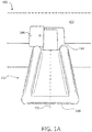
- FIG. 1a schematically depicts the evacuation slide 110 in a deployed state extending from the fuselage 102 of the aircraft 100.
- Conventional evacuation slides may be susceptible to undesirable deployment characteristics. Improper restraint mechanisms, among other factors, may cause conventional slides to deploy in an uncontrolled or unsafe manner. For example, if an evacuation slide is not properly restrained/controlled during deployment, portions or sections of the slide may sag downwards before being properly inflated and such sagging sections may get caught on portions of the aircraft and may be damaged or may otherwise create an unsafe evacuation environment. In another example, if an evacuation slide is not properly restrained, the toe end of a slide may extend too high relative to the ground/water. Such a deployment may cause the evacuation slide to "kite" (especially if the evacuation slide is deployed in high wind conditions) such that the toe end of the slide does not touch the ground, rendering the slide less usable. Furthermore, if the slide lifts off the ground above the level of the emergency exit door 106, the slide may even block the aircraft exit and prevent safe evacuation of passengers and crew.
- a restraint 120 (with momentary reference to FIGS. 1B and 1C ) that facilitates proper deployment of the evacuation slide 110.
- the restraint 120 may be generally configured to be coupled to one or more straps 150A, 150B (with momentary reference to FIG. 5 ) and the restraint 120 may have an adjustable tensile strength that allows for a controllably restrained deployment of the evacuation slide 110.
- the restraint 120 having adjustable tensile strength properties, may break in response to a predetermined tensile force exerted on the restraint 120 by deployment (e.g., inflation) of the evacuation slide 110.
- the evacuation slide 110 can be controllably, safely, and properly deployed to extend from a head end 114 of the evacuation slide 110 mounted to the aircraft 100 to a toe end 116 of the evacuation slide 110 that is contacting the ground (or water, in the event of a water landing).
- the evacuation slide 110 includes a longitudinal axis 115 that extends from the head end 114 to the toe end 116. While numerous details are included herein pertaining to utilizing the restraint 120 in conjunction with the evacuation slide 110 and in the context of an evacuation assembly of an aircraft, the restraint 120 may be utilized for other purposes and in other applications.
- the restraint 120 includes a longitudinal body 130, a plurality of engagement features 135, and a head 140.
- the longitudinal body 130 has a first end 131 and a second 132 and the plurality of engagement features 135 are distributed between the first end 131 and the second end 132, according to various embodiments.
- the head 140 is disposed at the first end 131 of the longitudinal body 130, according to various embodiments.
- the head 140 may define an aperture 144 and the head 140 may include a pawl 145.
- the longitudinal body 130, the plurality of engagement features 135, and the head 140 may be integrally formed and thus the restraint 120 may be a monolithic structure having a body portion (e.g., 130), multiple engagement features (e.g., 135), and a head portion (e.g., 140).
- a dimension of restraint 120 varies along at least a portion of a length of the longitudinal body 130. Said differently, over at least a portion of the longitudinal body 130 of the restraint 120, a dimension, such as a cross-sectional thickness 133, of the longitudinal body 130 or a cross-sectional thickness 138 of the plurality of engagement features 135 (or both) varies, according to various embodiments.
- the restraint 120 includes features that have non-uniform dimensions.
- a breaking load of the restraint is selectably adjustable, for example, by an operator, based on the dimension of at least one of the respective engagement feature and a section of the longitudinal body 130 adjacent the respective engagement feature, according to various embodiments.
- the restraint 120 may adjusted by an operator, as described in greater detail below, to break in response to a certain deployment condition (e.g., inflation of a first section of the evacuation slide 110 and/or inflation to a predetermined inflation pressure).
- the dimension of the longitudinal body 130 varies, either incrementally or continuously, along at least a portion of the length of the longitudinal body 130 from the first end 131 to the second end 132. In various embodiments, the dimension increases, either incrementally (in a step wise fashion) or continuously, along at least a portion of the length of the longitudinal body 130 from the second end 132 to the first end 131.
- the pawl 145 is configured to individually engage the plurality of engagement features 135 of the longitudinal body 130, according to various embodiments.
- the plurality of engagement features 135 may include lips, teeth, edges, grooves, channels, protrusions, rungs, and the like and the pawl 145 may include a feature that contacts the engagement features 135 to allow relative movement of the engagement features 135 in a first direction 121 but prevents relative movement of the engagement features 135 in a second direction 122.
- the pawl 145 may be configured to sequentially traverse the plurality of engagement features 135 in response to insertion, in a first direction 121, of the second end 132 through the aperture 144 of the head 140 but the pawl 145 may be configured to prevent retraction, in a second direction 122 opposite the first direction 121, of the longitudinal body 130 through the aperture 144 defined by the head 140 (e.g., engagement between the pawl 145 and a respective engagement feature of the plurality of engagement features 135 prevents retraction in the second direction 122).
- the pawl is generally disposed within the aperture 144 defined by the head 140.
- the restraint 120 By inserting the second end 132 of the longitudinal body 130 of the restraint 120 through the aperture 144 of the head 140 in the first direction 121, and because of the interlocked engagement between the pawl 145 and a respective engagement feature, which prevents movement retraction of the longitudinal body 130 in the second direction 122, the restraint 120 forms a closed loop 125.
- the tensile strength of the closed loop 125 is dependent upon the dimension of the restraint 120 in the vicinity of the pawl 145.
- a dimension of the engagement feature being retained/engaged by the pawl 145 e.g., the respective engagement feature
- a dimension of the longitudinal body in the vicinity of the respective engagement feature affects the tensile strength of the closed loop 125, which thereby affects the magnitude of the tensile force that will break the restraint 120.
- a user/operator may select the engagement position of the pawl 145 along the longitudinal body 130, thereby setting the tensile strength (e.g., the breaking point) of the restraint. Additional details and examples are included immediately below.
- the longitudinal body 130 includes two side arms 134 and the plurality of engagement features 135 include a plurality of rungs 136 extending between the two side arms 134 (e.g., the longitudinal body 130 may define openings or windows between the two side arms 134 and between adjacent rungs of the plurality of rungs 136).
- the dimension of the side arms 134 (e.g., the longitudinal body 130) and the dimension of the rungs 136 (e.g., the plurality of engagement features) vary along the length of the restraint 120.
- side arm 134A has a smaller dimension, such as a smaller cross-sectional diameter, than side arm 134B and rung 136A has a smaller dimension than rung 136B.
- the variation in the dimensions may be incremental or the variation may be a smooth, continuous transition.
- restraint 220 has a longitudinal body 230 that includes two side arms 234 and the restraint 220 also includes a plurality of engagement features 235 that are rungs 236 (that extend substantially perpendicular to the length of the longitudinal body 230).
- the rungs 236 of the restraint 220 have a constant dimension (e.g., cross-sectional diameter) but the side arms 234 of the restraint 220 vary along at least a portion of the length of the restraint 220.
- side arm 234A has a smaller cross-sectional dimension than side arm 234B while rung 236A has the same cross-sectional dimension as rung 236B.
- the variation in the cross-sectional dimension of the longitudinal body 230 imparts the adjustable tensile strength to the closed loop.
- restraint 320 has a longitudinal body 330 that includes two side arms 334 and the restraint 320 also includes a plurality of engagement features 335 that are rungs 336.
- the side arms 334 of the restraint 320 have a constant dimension (e.g., cross-sectional diameter) but the rungs 336 of the restraint 320 vary along at least a portion of the length of the restraint 320.
- rung 336A has a smaller cross-sectional dimension than rung 336B while side arm 334A has the same cross-sectional dimension as side arm 334B.
- the variation in the cross-sectional dimension of the plurality of engagement features 335 imparts the adjustable tensile strength to the closed loop.
- restraint 420 has a longitudinal body 430 that includes a single, central arm 434 and the restraint 420 also includes a plurality of engagement features 435 that are rungs 436 extending outwards from the central arm 434.
- the single, central arm 434 of the restraint 420 has a constant dimension (e.g., cross-sectional diameter) but the rungs 436 of the restraint 420 vary along at least a portion of the length of the restraint 420.
- rung 436A has a smaller cross-sectional dimension than rung 436B while central arm 434A has the same cross-sectional dimension as central arm 434B.
- the variation in the cross-sectional dimension of the plurality of engagement features 435 imparts the adjustable tensile strength to the closed loop.
- the pawl may be configured to engage rungs 436 that extend outwards from a central arm 434.
- an evacuation assembly of an aircraft includes an evacuation slide 110, one or more straps 150A, 150B, and one or more restraints 120A, 120B.
- the strap 150A may be coupled between the evacuation slide 110 and the aircraft 100 or the strap 150A may be coupled at two different locations along the evacuation slide 110.
- the restraint 120A may be coupled between the strap 150A and at least one of the evacuation slide 110 and the aircraft 100. Said differently, the restraint 120A is disposed at one end of the strap, either between the evacuation slide 110 and the strap 150A or between the strap 150A and the aircraft 100, according to various embodiments. For example, FIG.
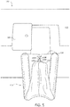
- FIG. 5 shows a schematic depiction of restraint 120A being coupled between the strap 150A and the toe end 116 of the evacuation slide 110 and
- FIG. 6 shows a depiction of restraint 120A being coupled between the strap 150A and another location (e.g., the head end 114) of the evacuation slide 110.
- the evacuation slide 110 depicted in FIG. 5 is in an intermediate deployment state, and the straps 150A, 150B, together with the restraints 120A, 120B restrain, limit, control, and/or guide the deployment of the evacuation slide 110.
- the inflation pressure may be such that the deploying evacuation slide 110 exerts a predetermined tensile force against/through the straps 150A, 150B and the restraints 120A, 120B.
- the restraints 120A, 120B may be configured to break at the predetermined tensile force to allow the evacuation slide 110 to continue its deployment in an orderly, controlled manner.
- multiple restraints 120A, 120B may be utilized with multiple straps 150A, 150B, and each restraint may be adjusted to have a closed loop with a different tensile strength, thereby enabling a staged deployment of the evacuation slide 110.
- the restraint 120A and/or a portion of the strap 150A may be partially enclosed by one or more protective layers 50 that prevent the restraint 120A from becoming a potentially harmful projectile in response to reaching its structural limit/threshold.
- the restraint is made from a plastic, composite, or other non-metallic material.
- the restraining straps and features of the evacuation assembly are free of shear pins or other metallic restraint mechanisms.
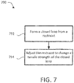
- method 790 of assembling an evacuation assembly of an aircraft may include forming a closed loop from a restraint at step 792 and adjusting the restraint to change a tensile strength of the closed loop at step 794.
- the closed loop may couple to either an evacuation slide or an aircraft (e.g., a fuselage, packboard, girt).
- the dimension of the restraint may vary along at least a portion of the restraint that forms the closed loop.
- the tensile strength of the closed loop may be dependent on the dimension.
- the closed loop is a first closed loop
- the restraint is a first restraint
- the strap is a first strap
- the dimension is a first dimension
- the tensile strength is a first tensile strength.
- the method 790 may further include forming a second closed loop from a second restraint, wherein the second closed loop couples a second strap to either the evacuation slide or the aircraft and adjusting the second restraint to change a second tensile strength of the second closed loop.
- a second dimension of the second restraint may vary along at least a portion of the second restraint that forms the second closed loop and the second tensile strength of the second closed loop may be dependent on the second dimension.
- the first dimension is different than the second dimension and the first tensile strength is different than the second tensile strength.
- any of the method or process descriptions may be executed in any order and are not necessarily limited to the order presented.
- any reference to singular includes plural embodiments, and any reference to more than one component or step may include a singular embodiment or step.
- Elements and steps in the figures are illustrated for simplicity and clarity and have not necessarily been rendered according to any particular sequence. For example, steps that may be performed concurrently or in different order are illustrated in the figures to help to improve understanding of embodiments of the present disclosure.
- Any reference to attached, fixed, connected or the like may include permanent, removable, temporary, partial, full and/or any other possible attachment option. Additionally, any reference to without contact (or similar phrases) may also include reduced contact or minimal contact. Surface shading lines may be used throughout the figures to denote different parts or areas but not necessarily to denote the same or different materials. In some cases, reference coordinates may be specific to each figure.
- references to "one embodiment”, “an embodiment”, “various embodiments”, etc. indicate that the embodiment described may include a particular feature, structure, or characteristic, but every embodiment may not necessarily include the particular feature, structure, or characteristic. Moreover, such phrases are not necessarily referring to the same embodiment. Further, when a particular feature, structure, or characteristic is described in connection with an embodiment, it is submitted that it is within the knowledge of one skilled in the art to affect such feature, structure, or characteristic in connection with other embodiments whether or not explicitly described. After reading the description, it will be apparent to one skilled in the relevant art(s) how to implement the disclosure in alternative embodiments.
Landscapes
- Engineering & Computer Science (AREA)
- General Engineering & Computer Science (AREA)
- Mechanical Engineering (AREA)
- Business, Economics & Management (AREA)
- Emergency Management (AREA)
- Aviation & Aerospace Engineering (AREA)
- Emergency Lowering Means (AREA)
- Aiming, Guidance, Guns With A Light Source, Armor, Camouflage, And Targets (AREA)
Abstract
Description
- The present disclosure relates to aircraft evacuation assemblies, and more specifically to restraints for evacuation slides.
- An evacuation slide assembly may include an inflatable slide that helps passengers disembark from an aircraft in the event of an emergency or other evacuation event. The slides may deploy from a door sill or a side of the aircraft fuselage. Controlling the deployment dynamics of an evacuation slide is often an important consideration that may affect the safety, efficiency, and overall feasibility of an evacuation.
- According to various embodiments, the present disclosure provides a restraint that includes a longitudinal body having a first end and a second end. The restraint may also include a plurality of engagement features distributed between the first end and the second end. The restraint also includes, according to various embodiments, a head disposed at the first end of the longitudinal body, the head defining an aperture and include a pawl. The pawl may be configured to engage an engagement feature of the plurality of engagement features. In various embodiments, a dimension of at least one of the longitudinal body and the plurality of engagement features varies along at least a portion of a length of the longitudinal body.
- In various embodiments, the dimension varies incrementally or continuously along at least the portion of the length of the longitudinal body from the first end to the second end. In various embodiments, the dimension increases incrementally or continuously along at least the portion of the length of the longitudinal body from the second end to the first end.
- In various embodiments, the pawl is configured to sequentially traverse the plurality of engagement features in response to insertion, in a first direction, of the second end of the longitudinal body through the aperture of the head. In various embodiments, engagement between the pawl and a respective engagement feature of the plurality of engagement features prevents retraction, in a second direction opposite the first direction, of the longitudinal body through the aperture of the head such that the restraint forms a closed loop.
- In various embodiments, a tensile strength of the closed loop is dependent upon the dimension of at least one of the respective engagement feature and a section of the longitudinal body adjacent the respective engagement feature. In various embodiments, a breaking load of the restraint is selectably adjustable based on the dimension of at least one of the respective engagement feature and a section of the longitudinal body adjacent the respective engagement feature. In various embodiments, the longitudinal body includes two side arms and the plurality of engagement features includes a plurality of rungs extending between the two side arms in a direction perpendicular to the length of the two side arms. The dimension may be a cross-sectional thickness of each of the side arms. The dimension may be a cross-sectional thickness each rung of the plurality of rungs. In various embodiments, the dimension is a cross-sectional thickness of each of the side arms and the plurality of rungs.
- Also disclosed herein, according to various embodiments, is an evacuation assembly of an aircraft. The evacuation assembly may include an evacuation slide, a strap coupled between the evacuation slide and the aircraft, and a restraint coupled between the strap and at least one of the evacuation slide and the aircraft. In various embodiments, a dimension of the restraint varies along at least a portion of a length of the restraint. In various embodiments, the restraint forms a closed loop such that a tensile strength of the closed loop is dependent upon the dimension. In various embodiments, the dimension varies incrementally or continuously along at least the portion of the length of the restraint. In various embodiments, the dimension increases incrementally or continuously along at least the portion of the length.
- In various embodiments, the restraint includes a longitudinal body having a first end and a second end. The restraint may further include a plurality of engagement features distributed between the first end and the second end. The dimension is of at least one of the longitudinal body and the plurality of engagement features. The restraint may also include a head disposed at the first end of the longitudinal body and the head may define an aperture and may include a pawl. The pawl may be configured to individually engage the plurality of engagement features.
- In various embodiments, the pawl is configured to sequentially traverse the plurality of engagement features in response to insertion, in a first direction, of the second end of the longitudinal body through the aperture of the head. In various embodiments, engagement between the pawl and a respective engagement feature of the plurality of engagement features prevents retraction, in a second direction opposite the first direction, of the longitudinal body through the aperture of the head such that the restraint forms the closed loop.
- In various embodiments, the longitudinal body includes two side arms and the plurality of engagement features includes a plurality of rungs extending between the two side arms in a direction perpendicular to the length of the two side arms. In various embodiments, the dimension is a cross-sectional thickness of each of the side arms. In various embodiments, the cross-sectional thickness of the each of the side arms increases incrementally or continuously along at least the portion of the length from the second end to the first end.
- Also disclosed herein, according to various embodiments, is a method of assembling an evacuation assembly of an aircraft. The method may include forming a closed loop from a restraint and adjusting the restraint to change a tensile strength of the closed loop. The closed loop may couple a strap to at least one of an evacuation slide and the aircraft and a dimension of the restraint may vary along at least a portion of the restraint that forms the closed loop. The tensile strength, according to various embodiments, is dependent upon the dimension. In various embodiments, the closed loop is a first closed loop, the restraint is a first restraint, the strap is a first strap, the dimension is a first dimension, and the tensile strength is a first tensile strength. The method may further include forming a second closed loop from a second restraint and adjusting the second restraint to change a second tensile strength of the second closed loop. The second closed loop couples a second strap to at least one of the evacuation slide and the aircraft and a second dimension of the second restraint varies along at least a portion of the second restraint that forms the second closed loop, according to various embodiments. The second tensile strength of the second closed loop may be dependent upon the second dimension. In various embodiments, the first dimension is different than the second dimension and the first tensile strength is different than the second tensile strength.
- The forgoing features and elements may be combined in various combinations without exclusivity, unless expressly indicated herein otherwise. These features and elements as well as the operation of the disclosed embodiments will become more apparent in light of the following description and accompanying drawings.
-
-
FIG. 1A is a schematic view of an aircraft showing an evacuation slide of an evacuation assembly in a deployed state, in accordance with various embodiments; -
FIG. 1B is a schematic view of a restraint, in accordance with various embodiments; -
FIG. 1C is a schematic perspective view of the restraint ofFIG. 1B , in accordance with various embodiments; -
FIG. 2 is a schematic side view of another implementation of the restraint, in accordance with various embodiments; -
FIG. 3 is a schematic side view of another implementation of the restraint, in accordance with various embodiments; -
FIG. 4 is a schematic side view of yet another implementation of the restraint, in accordance with various embodiments; -
FIG. 5 is a schematic view of an evacuation assembly including an evacuation slide in a stage of deployment, in accordance with various embodiments; -
FIG. 6 is a magnified view of a restraint forming a closed loop that is coupled to a strap of the evacuation assembly, in accordance with various embodiments; and -
FIG. 7 is a schematic flow chart diagram of a method of assembling an evacuation assembly of an aircraft, in accordance with various embodiments. - The subject matter of the present disclosure is particularly pointed out and distinctly claimed in the concluding portion of the specification. A more complete understanding of the present disclosure, however, may best be obtained by referring to the detailed description and claims when considered in connection with the drawing figures, wherein like numerals denote like elements.
- The detailed description of exemplary embodiments herein makes reference to the accompanying drawings, which show exemplary embodiments by way of illustration. While these exemplary embodiments are described in sufficient detail to enable those skilled in the art to practice the disclosures, it should be understood that other embodiments may be realized and that logical changes and adaptations in design and construction may be made in accordance with this disclosure and the teachings herein. Thus, the detailed description herein is presented for purposes of illustration only and not of limitation. Throughout the present disclosure, like reference numbers denote like elements. Accordingly, elements with like element numbering may be shown in the figures but may not be necessarily be repeated herein for the sake of clarity.
- A first component that is "axially outward" of a second component means that a first component is positioned at a greater distance in either longitudinal direction away from the longitudinal center of the composite component along its longitudinal axis than the second component. A first component that is "axially inward" of a second component means that the first component is positioned closer to the longitudinal center of the composite component along its longitudinal axis than the second component.
- As used herein, "aft" refers to the direction associated with the tail (e.g., the back end) of an aircraft, or generally, to the direction of exhaust of the gas turbine. As used herein, "forward" refers to the direction associated with the nose (e.g., the front end) of an aircraft, or generally, to the direction of flight or motion.
- In various embodiments, and with reference to
FIG. 1A , anevacuation slide 110 of an evacuation assembly of anaircraft 100 is provided.Aircraft 100 may include afuselage 102 with wings fixed to thefuselage 102.Emergency exit door 106 may disposed on thefuselage 102 over one of the wings or at some other location along thefuselage 102. Theevacuation slide 110 and other components of the evacuation assembly may be housed within a packboard or other compartment mounted to theaircraft 100. The evacuation assembly may jettison a blowout panel to deploy theevacuation slide 110, such as an inflatable evacuation slide, in response to theemergency exit door 106 opening or in response to another evacuation event. For example,FIG. 1a schematically depicts theevacuation slide 110 in a deployed state extending from thefuselage 102 of theaircraft 100. - Conventional evacuation slides may be susceptible to undesirable deployment characteristics. Improper restraint mechanisms, among other factors, may cause conventional slides to deploy in an uncontrolled or unsafe manner. For example, if an evacuation slide is not properly restrained/controlled during deployment, portions or sections of the slide may sag downwards before being properly inflated and such sagging sections may get caught on portions of the aircraft and may be damaged or may otherwise create an unsafe evacuation environment. In another example, if an evacuation slide is not properly restrained, the toe end of a slide may extend too high relative to the ground/water. Such a deployment may cause the evacuation slide to "kite" (especially if the evacuation slide is deployed in high wind conditions) such that the toe end of the slide does not touch the ground, rendering the slide less usable. Furthermore, if the slide lifts off the ground above the level of the
emergency exit door 106, the slide may even block the aircraft exit and prevent safe evacuation of passengers and crew. - Disclosed herein, according to various embodiments, is a restraint 120 (with momentary reference to
FIGS. 1B and 1C ) that facilitates proper deployment of theevacuation slide 110. Therestraint 120, as described in greater detail below, may be generally configured to be coupled to one ormore straps FIG. 5 ) and therestraint 120 may have an adjustable tensile strength that allows for a controllably restrained deployment of theevacuation slide 110. Said differently, therestraint 120, having adjustable tensile strength properties, may break in response to a predetermined tensile force exerted on therestraint 120 by deployment (e.g., inflation) of theevacuation slide 110. Thus, theevacuation slide 110 can be controllably, safely, and properly deployed to extend from ahead end 114 of theevacuation slide 110 mounted to theaircraft 100 to atoe end 116 of theevacuation slide 110 that is contacting the ground (or water, in the event of a water landing). In various embodiments, theevacuation slide 110 includes alongitudinal axis 115 that extends from thehead end 114 to thetoe end 116. While numerous details are included herein pertaining to utilizing therestraint 120 in conjunction with theevacuation slide 110 and in the context of an evacuation assembly of an aircraft, therestraint 120 may be utilized for other purposes and in other applications. - In various embodiments, and with reference to
FIGS. 1B and 1C , therestraint 120 includes alongitudinal body 130, a plurality of engagement features 135, and ahead 140. Thelongitudinal body 130 has afirst end 131 and a second 132 and the plurality of engagement features 135 are distributed between thefirst end 131 and thesecond end 132, according to various embodiments. Thehead 140 is disposed at thefirst end 131 of thelongitudinal body 130, according to various embodiments. Thehead 140 may define anaperture 144 and thehead 140 may include apawl 145. Thelongitudinal body 130, the plurality of engagement features 135, and thehead 140 may be integrally formed and thus therestraint 120 may be a monolithic structure having a body portion (e.g., 130), multiple engagement features (e.g., 135), and a head portion (e.g., 140). - In various embodiments, a dimension of
restraint 120 varies along at least a portion of a length of thelongitudinal body 130. Said differently, over at least a portion of thelongitudinal body 130 of therestraint 120, a dimension, such as across-sectional thickness 133, of thelongitudinal body 130 or across-sectional thickness 138 of the plurality of engagement features 135 (or both) varies, according to various embodiments. Thus, therestraint 120 includes features that have non-uniform dimensions. As described in greater detail below, the non-uniformity of the dimensions along the length of therestraint 120 allows the tensile strength of the restraint to be adjusted, which changes the magnitude of the tensile force that will cause therestraint 120 to break, thereby allowing the deployment of theevacuation slide 110 to be controlled. Accordingly, a breaking load of the restraint is selectably adjustable, for example, by an operator, based on the dimension of at least one of the respective engagement feature and a section of thelongitudinal body 130 adjacent the respective engagement feature, according to various embodiments. For example, therestraint 120 may adjusted by an operator, as described in greater detail below, to break in response to a certain deployment condition (e.g., inflation of a first section of theevacuation slide 110 and/or inflation to a predetermined inflation pressure). - In various embodiments, for example, the dimension of the
longitudinal body 130 varies, either incrementally or continuously, along at least a portion of the length of thelongitudinal body 130 from thefirst end 131 to thesecond end 132. In various embodiments, the dimension increases, either incrementally (in a step wise fashion) or continuously, along at least a portion of the length of thelongitudinal body 130 from thesecond end 132 to thefirst end 131. - The
pawl 145 is configured to individually engage the plurality of engagement features 135 of thelongitudinal body 130, according to various embodiments. The plurality of engagement features 135 may include lips, teeth, edges, grooves, channels, protrusions, rungs, and the like and thepawl 145 may include a feature that contacts the engagement features 135 to allow relative movement of the engagement features 135 in afirst direction 121 but prevents relative movement of the engagement features 135 in asecond direction 122. Said differently, thepawl 145 may be configured to sequentially traverse the plurality of engagement features 135 in response to insertion, in afirst direction 121, of thesecond end 132 through theaperture 144 of thehead 140 but thepawl 145 may be configured to prevent retraction, in asecond direction 122 opposite thefirst direction 121, of thelongitudinal body 130 through theaperture 144 defined by the head 140 (e.g., engagement between thepawl 145 and a respective engagement feature of the plurality of engagement features 135 prevents retraction in the second direction 122). In various embodiments, the pawl is generally disposed within theaperture 144 defined by thehead 140. - By inserting the
second end 132 of thelongitudinal body 130 of therestraint 120 through theaperture 144 of thehead 140 in thefirst direction 121, and because of the interlocked engagement between thepawl 145 and a respective engagement feature, which prevents movement retraction of thelongitudinal body 130 in thesecond direction 122, therestraint 120 forms aclosed loop 125. In various embodiments, the tensile strength of theclosed loop 125 is dependent upon the dimension of therestraint 120 in the vicinity of thepawl 145. Said differently, a dimension of the engagement feature being retained/engaged by the pawl 145 (e.g., the respective engagement feature) and/or a dimension of the longitudinal body in the vicinity of the respective engagement feature affects the tensile strength of theclosed loop 125, which thereby affects the magnitude of the tensile force that will break therestraint 120. Accordingly, a user/operator may select the engagement position of thepawl 145 along thelongitudinal body 130, thereby setting the tensile strength (e.g., the breaking point) of the restraint. Additional details and examples are included immediately below. - In various embodiments, and with reference to
FIG. 1B , thelongitudinal body 130 includes twoside arms 134 and the plurality of engagement features 135 include a plurality ofrungs 136 extending between the two side arms 134 (e.g., thelongitudinal body 130 may define openings or windows between the twoside arms 134 and between adjacent rungs of the plurality of rungs 136). In various embodiments, and with continued reference toFIG. 1B , the dimension of the side arms 134 (e.g., the longitudinal body 130) and the dimension of the rungs 136 (e.g., the plurality of engagement features) vary along the length of therestraint 120. For example,side arm 134A has a smaller dimension, such as a smaller cross-sectional diameter, thanside arm 134B andrung 136A has a smaller dimension thanrung 136B. The variation in the dimensions may be incremental or the variation may be a smooth, continuous transition. - In various embodiments, and with reference to
FIG. 2 ,restraint 220 has alongitudinal body 230 that includes twoside arms 234 and therestraint 220 also includes a plurality of engagement features 235 that are rungs 236 (that extend substantially perpendicular to the length of the longitudinal body 230). In various embodiments, and with reference torestraint 220 inFIG. 2 , therungs 236 of therestraint 220 have a constant dimension (e.g., cross-sectional diameter) but theside arms 234 of therestraint 220 vary along at least a portion of the length of therestraint 220. For example,side arm 234A has a smaller cross-sectional dimension thanside arm 234B whilerung 236A has the same cross-sectional dimension asrung 236B. In such embodiments, the variation in the cross-sectional dimension of the longitudinal body 230 (e.g., the side arms 234) imparts the adjustable tensile strength to the closed loop. - In various embodiments, and with reference to
FIG. 3 ,restraint 320 has alongitudinal body 330 that includes twoside arms 334 and therestraint 320 also includes a plurality of engagement features 335 that arerungs 336. In various embodiments, and with reference torestraint 320 inFIG. 3 , theside arms 334 of therestraint 320 have a constant dimension (e.g., cross-sectional diameter) but therungs 336 of therestraint 320 vary along at least a portion of the length of therestraint 320. For example,rung 336A has a smaller cross-sectional dimension thanrung 336B while side arm 334A has the same cross-sectional dimension asside arm 334B. In such embodiments, the variation in the cross-sectional dimension of the plurality of engagement features 335 (e.g., the rungs 336) imparts the adjustable tensile strength to the closed loop. - In various embodiments, and with reference to
FIG. 4 ,restraint 420 has alongitudinal body 430 that includes a single,central arm 434 and therestraint 420 also includes a plurality of engagement features 435 that arerungs 436 extending outwards from thecentral arm 434. In various embodiments, and with reference torestraint 420 inFIG. 4 , the single,central arm 434 of therestraint 420 has a constant dimension (e.g., cross-sectional diameter) but therungs 436 of therestraint 420 vary along at least a portion of the length of therestraint 420. For example,rung 436A has a smaller cross-sectional dimension thanrung 436B whilecentral arm 434A has the same cross-sectional dimension ascentral arm 434B. In such embodiments, the variation in the cross-sectional dimension of the plurality of engagement features 435 (e.g., the rungs 436) imparts the adjustable tensile strength to the closed loop. In various embodiments, the pawl may be configured to engagerungs 436 that extend outwards from acentral arm 434. - In various embodiments, and with reference to
FIGS. 5 and6 , an evacuation assembly of an aircraft is provided. The evacuation assembly includes anevacuation slide 110, one ormore straps more restraints strap 150A may be coupled between theevacuation slide 110 and theaircraft 100 or thestrap 150A may be coupled at two different locations along theevacuation slide 110. Therestraint 120A may be coupled between thestrap 150A and at least one of theevacuation slide 110 and theaircraft 100. Said differently, therestraint 120A is disposed at one end of the strap, either between theevacuation slide 110 and thestrap 150A or between thestrap 150A and theaircraft 100, according to various embodiments. For example,FIG. 5 shows a schematic depiction ofrestraint 120A being coupled between thestrap 150A and thetoe end 116 of theevacuation slide 110 andFIG. 6 shows a depiction ofrestraint 120A being coupled between thestrap 150A and another location (e.g., the head end 114) of theevacuation slide 110. - The
evacuation slide 110 depicted inFIG. 5 is in an intermediate deployment state, and thestraps restraints evacuation slide 110. For example, in response to theevacuation slide 110 being inflated to a certain extent, the inflation pressure may be such that the deployingevacuation slide 110 exerts a predetermined tensile force against/through thestraps restraints restraints restraints evacuation slide 110 to continue its deployment in an orderly, controlled manner. In various embodiments,multiple restraints multiple straps evacuation slide 110. In various embodiments, and with reference toFIG. 6 , therestraint 120A and/or a portion of thestrap 150A may be partially enclosed by one or moreprotective layers 50 that prevent therestraint 120A from becoming a potentially harmful projectile in response to reaching its structural limit/threshold. - In various embodiments, the restraint is made from a plastic, composite, or other non-metallic material. In various embodiments, the restraining straps and features of the evacuation assembly are free of shear pins or other metallic restraint mechanisms.
- In various embodiments, and with reference to
FIG. 7 ,method 790 of assembling an evacuation assembly of an aircraft is provided. Themethod 790 may include forming a closed loop from a restraint atstep 792 and adjusting the restraint to change a tensile strength of the closed loop atstep 794. The closed loop may couple to either an evacuation slide or an aircraft (e.g., a fuselage, packboard, girt). The dimension of the restraint may vary along at least a portion of the restraint that forms the closed loop. The tensile strength of the closed loop may be dependent on the dimension. - In various embodiments, the closed loop is a first closed loop, the restraint is a first restraint, the strap is a first strap, the dimension is a first dimension, and the tensile strength is a first tensile strength. In such embodiments, the
method 790 may further include forming a second closed loop from a second restraint, wherein the second closed loop couples a second strap to either the evacuation slide or the aircraft and adjusting the second restraint to change a second tensile strength of the second closed loop. A second dimension of the second restraint may vary along at least a portion of the second restraint that forms the second closed loop and the second tensile strength of the second closed loop may be dependent on the second dimension. In various embodiments, the first dimension is different than the second dimension and the first tensile strength is different than the second tensile strength. - Benefits, other advantages, and solutions to problems have been described herein with regard to specific embodiments. Furthermore, the connecting lines shown in the various figures contained herein are intended to represent exemplary functional relationships and/or physical couplings between the various elements. It should be noted that many alternative or additional functional relationships or physical connections may be present in a practical system. However, the benefits, advantages, solutions to problems, and any elements that may cause any benefit, advantage, or solution to occur or become more pronounced are not to be construed as critical, required, or essential features or elements of the disclosure.
- The scope of the disclosure is accordingly to be limited by nothing other than the appended claims, in which reference to an element in the singular is not intended to mean "one and only one" unless explicitly so stated, but rather "one or more." It is to be understood that unless specifically stated otherwise, references to "a," "an," and/or "the" may include one or more than one and that reference to an item in the singular may also include the item in the plural. All ranges and ratio limits disclosed herein may be combined.
- Moreover, where a phrase similar to "at least one of A, B, and C" is used in the claims, it is intended that the phrase be interpreted to mean that A alone may be present in an embodiment, B alone may be present in an embodiment, C alone may be present in an embodiment, or that any combination of the elements A, B and C may be present in a single embodiment; for example, A and B, A and C, B and C, or A and B and C. Different cross-hatching is used throughout the figures to denote different parts but not necessarily to denote the same or different materials.
- The steps recited in any of the method or process descriptions may be executed in any order and are not necessarily limited to the order presented. Furthermore, any reference to singular includes plural embodiments, and any reference to more than one component or step may include a singular embodiment or step. Elements and steps in the figures are illustrated for simplicity and clarity and have not necessarily been rendered according to any particular sequence. For example, steps that may be performed concurrently or in different order are illustrated in the figures to help to improve understanding of embodiments of the present disclosure.
- Any reference to attached, fixed, connected or the like may include permanent, removable, temporary, partial, full and/or any other possible attachment option. Additionally, any reference to without contact (or similar phrases) may also include reduced contact or minimal contact. Surface shading lines may be used throughout the figures to denote different parts or areas but not necessarily to denote the same or different materials. In some cases, reference coordinates may be specific to each figure.
- Systems, methods and apparatus are provided herein. In the detailed description herein, references to "one embodiment", "an embodiment", "various embodiments", etc., indicate that the embodiment described may include a particular feature, structure, or characteristic, but every embodiment may not necessarily include the particular feature, structure, or characteristic. Moreover, such phrases are not necessarily referring to the same embodiment. Further, when a particular feature, structure, or characteristic is described in connection with an embodiment, it is submitted that it is within the knowledge of one skilled in the art to affect such feature, structure, or characteristic in connection with other embodiments whether or not explicitly described. After reading the description, it will be apparent to one skilled in the relevant art(s) how to implement the disclosure in alternative embodiments.
- Furthermore, no element, component, or method step in the present disclosure is intended to be dedicated to the public regardless of whether the element, component, or method step is explicitly recited in the claims. No claim element is intended to invoke 35 U.S.C. 112(f) unless the element is expressly recited using the phrase "means for." As used herein, the terms "comprises", "comprising", or any other variation thereof, are intended to cover a non-exclusive inclusion, such that a process, method, article, or apparatus that comprises a list of elements does not include only those elements but may include other elements not expressly listed or inherent to such process, method, article, or apparatus.
Claims (15)
- A restraint (120, 220, 420) comprising:a longitudinal body (130, 230, 330) having a first end (131) and a second end (132);a plurality of engagement features (135) distributed between the first end (131) and the second end (132) of the longitudinal body (130, 230, 330), wherein a dimension of at least one of the longitudinal body (130, 230, 330) and the plurality of engagement features (135) varies along at least a portion of a length of the longitudinal body (130, 230, 330); anda head (140) disposed at the first end of the longitudinal body (130, 230, 330), the head (140) defining an aperture and comprising a pawl (145), wherein the pawl (145) is configured to engage an engagement feature (135) of the plurality of engagement features (135).
- The restraint of claim 1, wherein the dimension varies at least one of incrementally or continuously along at least the portion of the length of the longitudinal body (130, 230, 330) from the first end (131) to the second end (132).
- The restraint of claim 1 or 2, wherein the dimension increases incrementally or continuously along at least the portion of the length of the longitudinal body (130, 230, 330) from the second end (132) to the first end (131).
- The restraint of claim 1, 2 or 3, wherein:the pawl (145) is configured to sequentially traverse the plurality of engagement features (135) in response to insertion, in a first direction, of the second end of the longitudinal body (130, 230, 330) through the aperture of the head (140); andengagement between the pawl (145) and a respective engagement feature (135) of the plurality of engagement features (135) prevents retraction, in a second direction opposite the first direction, of the longitudinal body (130, 230, 330) through the aperture of the head such that the restraint forms a closed loop.
- The restraint of claim 4, wherein a tensile strength of the closed loop is dependent upon the dimension of at least one of the respective engagement feature(135) and a section of the longitudinal body (130, 230, 330) adjacent the respective engagement feature (135), or
wherein a breaking load of the restraint is selectably adjustable based on the dimension of at least one of the respective engagement feature (135) and a section of the longitudinal body (130, 230, 330) adjacent the respective engagement feature (135). - The restraint of any preceding claim, wherein the longitudinal body (130, 230, 330) comprises two side arms (134) and the plurality of engagement features (135) comprises a plurality of rungs (136) extending between the two side arms (134) in a direction perpendicular to the length of the two side arms (134), and preferably
wherein the dimension is at least one of a cross-sectional thickness of each of the side arms (134) and a cross-sectional thickness of the plurality of rungs (136). - The restraint of any preceding claim, wherein the restraint has a monolithic structure and thus the longitudinal body (130, 230, 330), the plurality of engagement features (135), and the head (140) are integrally formed of a single material.
- An evacuation assembly of an aircraft (100), the evacuation assembly comprising:an evacuation slide (110);a strap coupled between the evacuation slide (110) and the aircraft (100); anda restraint (120, 220, 420) coupled between the strap and at least one of the evacuation slide (110) and the aircraft (100), wherein a dimension of the restraint (120, 220, 420) varies along at least a portion of a length of the restraint (120, 220, 420).
- The evacuation assembly of claim 8, wherein the restraint (120, 220, 420) forms a closed loop, wherein a tensile strength of the closed loop is dependent upon the dimension.
- The evacuation assembly of claim 9, wherein the dimension varies incrementally or continuously along at least the portion of the length of the restraint (120, 220, 420), or
wherein the dimension increases incrementally or continuously along at least the portion of the length. - The evacuation assembly of claim 8, 9 or 10, wherein the restraint (120, 220, 420) comprises:a longitudinal body (130, 230, 330) having a first end (131) and a second end (132);a plurality of engagement features (135) distributed between the first end (131) and the second end (132) of the longitudinal body (130, 230, 330), wherein the dimension is of at least one of the longitudinal body (130, 230, 330) and the plurality of engagement features (135); anda head (140) disposed at the first end of the longitudinal body (130, 230, 330), the head (140) defining an aperture and comprising a pawl (145), wherein the pawl (145) is configured to individually engage the plurality of engagement features (135).
- The evacuation assembly of claim 11, wherein:the pawl (145) is configured to sequentially traverse the plurality of engagement features (135) in response to insertion, in a first direction, of the second end of the longitudinal body (130, 230, 330) through the aperture of the head (140); andengagement between the pawl (145) and a respective engagement feature of the plurality of engagement features (135) prevents retraction, in a second direction opposite the first direction, of the longitudinal body (130, 230, 330) through the aperture of the head (141) such that the restraint forms the closed loop, and preferablywherein the longitudinal body (130, 230, 330) comprises two side arms (134) and the plurality of engagement features (135) comprises a plurality of rungs (136) extending between the two side arms (134) in a direction perpendicular to the length of the two side arms (134), and preferablywherein the dimension is a cross-sectional thickness of the side arms (134).
- The evacuation assembly of any of claims 8 to 12, wherein the restraint (120, 220, 420) is made from a non-metallic material.
- A method of assembling an evacuation assembly of an aircraft (100), the method comprising:forming a closed loop from a restraint (120, 220, 420), wherein the closed loop couples a strap to at least one of an evacuation slide (110) and the aircraft (100), wherein a dimension of the restraint (120, 220, 420) varies along at least a portion of the restraint (120, 220, 420) that forms the closed loop; andadjusting the restraint (120, 220, 420) to change a tensile strength of the closed loop, wherein the tensile strength of the closed loop is dependent upon the dimension.
- The method of claim 14, wherein the closed loop is a first closed loop, the restraint (120, 220, 420) is a first restraint, the strap is a first strap, the dimension is a first dimension, and the tensile strength is a first tensile strength, wherein the method further comprises:forming a second closed loop from a second restraint (120, 220, 420), wherein the second closed loop couples a second strap to at least one of the evacuation slide (110) and the aircraft (100), wherein a second dimension of the second restraint varies along at least a portion of the second restraint that forms the second closed loop; andadjusting the second restraint to change a second tensile strength of the second closed loop, wherein the second tensile strength of the second closed loop is dependent upon the second dimension;wherein the first dimension is different than the second dimension and the first tensile strength is different than the second tensile strength.
Applications Claiming Priority (1)
| Application Number | Priority Date | Filing Date | Title |
|---|---|---|---|
| US15/599,270 US10494110B2 (en) | 2017-05-18 | 2017-05-18 | Evacuation slide restraint |
Publications (2)
| Publication Number | Publication Date |
|---|---|
| EP3403930A1 true EP3403930A1 (en) | 2018-11-21 |
| EP3403930B1 EP3403930B1 (en) | 2023-03-22 |
Family
ID=62196461
Family Applications (1)
| Application Number | Title | Priority Date | Filing Date |
|---|---|---|---|
| EP18172874.2A Active EP3403930B1 (en) | 2017-05-18 | 2018-05-17 | Evacuation slide restraint |
Country Status (2)
| Country | Link |
|---|---|
| US (2) | US10494110B2 (en) |
| EP (1) | EP3403930B1 (en) |
Cited By (2)
| Publication number | Priority date | Publication date | Assignee | Title |
|---|---|---|---|---|
| US10494110B2 (en) * | 2017-05-18 | 2019-12-03 | Goodrich Corporation | Evacuation slide restraint |
| US11242154B2 (en) * | 2017-04-27 | 2022-02-08 | Goodrich Corporation | Yoke strap with shock absorber |
Families Citing this family (10)
| Publication number | Priority date | Publication date | Assignee | Title |
|---|---|---|---|---|
| US10703495B2 (en) * | 2017-01-13 | 2020-07-07 | Goodrich Corporation | Secondary release arrangement for evacuation slide systems |
| US10556697B2 (en) * | 2017-01-13 | 2020-02-11 | Goodrich Corporation | Light weight restraint for evacuation slide systems |
| US10486818B2 (en) | 2017-01-17 | 2019-11-26 | Goodrich Corporation | Shock absorbing evacuation system restraint |
| US10836498B2 (en) * | 2017-03-22 | 2020-11-17 | Goodrich Corporation | Light weight variable force restraint |
| US10793280B2 (en) * | 2017-05-12 | 2020-10-06 | Goodrich Corporation | Evacuation system with wind lift deterrent |
| US11485502B2 (en) | 2019-08-19 | 2022-11-01 | Goodrich Corporation | Girt boarding aid for evacuation slide |
| US20210354836A1 (en) * | 2020-05-12 | 2021-11-18 | Goodrich Corporation | Symmetrical dual action restraint |
| US11572181B2 (en) * | 2020-05-15 | 2023-02-07 | Goodrich Corporation | Stretch control system for inflatable evacuation slide |
| US20220402618A1 (en) * | 2021-06-16 | 2022-12-22 | Goodrich Corporation | Automatic readiness indication for aircraft emergency evacuation |
| US12497179B2 (en) * | 2022-03-08 | 2025-12-16 | Goodrich Corporation | Stretch sensor assembly and method of assembling stretch sensor assemblies for evacuation system inflatables |
Citations (6)
| Publication number | Priority date | Publication date | Assignee | Title |
|---|---|---|---|---|
| US3606939A (en) * | 1969-03-06 | 1971-09-21 | Garrett Corp | Inflatable escape slide |
| US3991444A (en) * | 1976-02-18 | 1976-11-16 | Panduit Corporation | Releasable cable tie |
| US4567977A (en) * | 1984-05-14 | 1986-02-04 | The B. F. Goodrich Company | Delayed restraint release device for inflatable escape slides |
| DE8903806U1 (en) * | 1989-03-28 | 1989-05-18 | Paul Hellermann Gmbh, 2080 Pinneberg | Device for tying elongated objects such as cables |
| EP0660018A1 (en) * | 1993-12-22 | 1995-06-28 | Kato Hatsujyo Co., Ltd. | A tie |
| EP0782957A2 (en) * | 1996-01-02 | 1997-07-09 | The B.F. Goodrich Company | Deployment control for inflatable escape slide |
Family Cites Families (18)
| Publication number | Priority date | Publication date | Assignee | Title |
|---|---|---|---|---|
| US3391771A (en) * | 1966-11-02 | 1968-07-09 | Ind Covers Inc | Tie-back assembly for aircraft escape slide |
| US3463266A (en) * | 1968-04-29 | 1969-08-26 | Ind Covers Inc | Extensible escape slide |
| US3621383A (en) * | 1970-06-02 | 1971-11-16 | Eastern Air Lines Inc | Lighting system for folded inflatable escape slides with means for testing system with slide in folded condition |
| US3897861A (en) * | 1973-08-13 | 1975-08-05 | Garrett Corp | Inflatable evacuation slide intermediate release system |
| US3973645A (en) * | 1975-08-15 | 1976-08-10 | The Garrett Corporation | Inflatable evacuation slide |
| US4460062A (en) * | 1982-11-22 | 1984-07-17 | The B. F. Goodrich Company | Delayed restraint release device for inflatable escape slides |
| US5906340A (en) * | 1997-05-29 | 1999-05-25 | The B.F. Goodrich Company | Inflatable escape slide assembly |
| DE19949484C1 (en) * | 1999-10-14 | 2000-12-07 | Eads Airbus Gmbh | Emergency chute for transferring persons from a high-level exit opening onto the ground comprises a transfer path in the form of a conveyor belt provided with a speed-controllable drive unit |
| US6814183B2 (en) * | 2002-10-17 | 2004-11-09 | Goodrich Corporation | Extensible evacuation slide |
| US8215586B2 (en) * | 2009-04-08 | 2012-07-10 | Air Cruisers Company | Evacuation slide systems |
| US10233666B2 (en) * | 2016-12-19 | 2019-03-19 | Goodrich Corporation | Telescopic canopy support for an inflatable evacuation device |
| US10556697B2 (en) * | 2017-01-13 | 2020-02-11 | Goodrich Corporation | Light weight restraint for evacuation slide systems |
| US10486818B2 (en) * | 2017-01-17 | 2019-11-26 | Goodrich Corporation | Shock absorbing evacuation system restraint |
| US10836498B2 (en) * | 2017-03-22 | 2020-11-17 | Goodrich Corporation | Light weight variable force restraint |
| US10647436B2 (en) * | 2017-04-27 | 2020-05-12 | Goodrich Corporation | Yoke strap with shock absorber |
| US10793280B2 (en) * | 2017-05-12 | 2020-10-06 | Goodrich Corporation | Evacuation system with wind lift deterrent |
| US10494110B2 (en) * | 2017-05-18 | 2019-12-03 | Goodrich Corporation | Evacuation slide restraint |
| US10189573B2 (en) * | 2017-05-19 | 2019-01-29 | Goodrich Corporation | Off-wing slide raft |
-
2017
- 2017-05-18 US US15/599,270 patent/US10494110B2/en active Active
-
2018
- 2018-05-17 EP EP18172874.2A patent/EP3403930B1/en active Active
-
2019
- 2019-10-25 US US16/663,747 patent/US11235883B2/en active Active
Patent Citations (6)
| Publication number | Priority date | Publication date | Assignee | Title |
|---|---|---|---|---|
| US3606939A (en) * | 1969-03-06 | 1971-09-21 | Garrett Corp | Inflatable escape slide |
| US3991444A (en) * | 1976-02-18 | 1976-11-16 | Panduit Corporation | Releasable cable tie |
| US4567977A (en) * | 1984-05-14 | 1986-02-04 | The B. F. Goodrich Company | Delayed restraint release device for inflatable escape slides |
| DE8903806U1 (en) * | 1989-03-28 | 1989-05-18 | Paul Hellermann Gmbh, 2080 Pinneberg | Device for tying elongated objects such as cables |
| EP0660018A1 (en) * | 1993-12-22 | 1995-06-28 | Kato Hatsujyo Co., Ltd. | A tie |
| EP0782957A2 (en) * | 1996-01-02 | 1997-07-09 | The B.F. Goodrich Company | Deployment control for inflatable escape slide |
Cited By (5)
| Publication number | Priority date | Publication date | Assignee | Title |
|---|---|---|---|---|
| US11242154B2 (en) * | 2017-04-27 | 2022-02-08 | Goodrich Corporation | Yoke strap with shock absorber |
| US20220119118A1 (en) * | 2017-04-27 | 2022-04-21 | Goodrich Corporation | Yoke strap with shock absorber |
| US11731771B2 (en) | 2017-04-27 | 2023-08-22 | Goodrich Corporation | Yoke strap with shock absorber |
| US10494110B2 (en) * | 2017-05-18 | 2019-12-03 | Goodrich Corporation | Evacuation slide restraint |
| US11235883B2 (en) | 2017-05-18 | 2022-02-01 | Goodrich Corporation | Evacuation slide restraint |
Also Published As
| Publication number | Publication date |
|---|---|
| US11235883B2 (en) | 2022-02-01 |
| US20200055609A1 (en) | 2020-02-20 |
| US10494110B2 (en) | 2019-12-03 |
| EP3403930B1 (en) | 2023-03-22 |
| US20180334256A1 (en) | 2018-11-22 |
Similar Documents
| Publication | Publication Date | Title |
|---|---|---|
| US11235883B2 (en) | Evacuation slide restraint | |
| US10118707B2 (en) | Aircraft parachute deployment autopilot | |
| US11964769B2 (en) | Light weight variable force restraint | |
| EP3348482B1 (en) | Light weight restraint for evacuation slide systems | |
| US10752368B2 (en) | Asymmetric yoke | |
| US20130200217A1 (en) | Restraints principally for inflatable evacuation systems | |
| US7648105B2 (en) | Deployment brake release for a parachute | |
| EP3395689B1 (en) | Yoke strap with shock absorber | |
| US10611489B2 (en) | Evacuation system with an extendable head end | |
| EP3517443B1 (en) | Aircraft sill height compensating evacuation system | |
| US7416158B2 (en) | Continuous disreefing apparatus for parachute | |
| EP3075659B1 (en) | Apogee enhancing ejection seat stabilization drogue chute | |
| US12286233B2 (en) | Parachute assemblies with multi-stage reefing | |
| US12139263B2 (en) | Inflatable girt for evacuation slide | |
| US20210354836A1 (en) | Symmetrical dual action restraint | |
| EP3321182B1 (en) | Redundant layer for inflatable evacuation component | |
| EP3816051A1 (en) | Integrated truss restraint | |
| EP4273045B1 (en) | Inflatable girt for evacuation slide | |
| US20250368337A1 (en) | Evacuation slide/raft daisy chain release mechanism | |
| EP4159625A1 (en) | Reusable releasable restraint for evacuation assemblies | |
| US20180319507A1 (en) | Evacuation slide connector | |
| Rutledge et al. | A textile vent hoop replacement for parachute vent lines | |
| KOLEGA et al. | Vent modification of large ribbon parachutes to enhance cluster performance | |
| Stein et al. | The Development of a 100-ft Drogue Parachute for the X-38 Spacecraft |
Legal Events
| Date | Code | Title | Description |
|---|---|---|---|
| PUAI | Public reference made under article 153(3) epc to a published international application that has entered the european phase |
Free format text: ORIGINAL CODE: 0009012 |
|
| STAA | Information on the status of an ep patent application or granted ep patent |
Free format text: STATUS: THE APPLICATION HAS BEEN PUBLISHED |
|
| AK | Designated contracting states |
Kind code of ref document: A1 Designated state(s): AL AT BE BG CH CY CZ DE DK EE ES FI FR GB GR HR HU IE IS IT LI LT LU LV MC MK MT NL NO PL PT RO RS SE SI SK SM TR |
|
| AX | Request for extension of the european patent |
Extension state: BA ME |
|
| STAA | Information on the status of an ep patent application or granted ep patent |
Free format text: STATUS: REQUEST FOR EXAMINATION WAS MADE |
|
| 17P | Request for examination filed |
Effective date: 20190521 |
|
| RBV | Designated contracting states (corrected) |
Designated state(s): AL AT BE BG CH CY CZ DE DK EE ES FI FR GB GR HR HU IE IS IT LI LT LU LV MC MK MT NL NO PL PT RO RS SE SI SK SM TR |
|
| STAA | Information on the status of an ep patent application or granted ep patent |
Free format text: STATUS: EXAMINATION IS IN PROGRESS |
|
| 17Q | First examination report despatched |
Effective date: 20210602 |
|
| GRAP | Despatch of communication of intention to grant a patent |
Free format text: ORIGINAL CODE: EPIDOSNIGR1 |
|
| STAA | Information on the status of an ep patent application or granted ep patent |
Free format text: STATUS: GRANT OF PATENT IS INTENDED |
|
| INTG | Intention to grant announced |
Effective date: 20221004 |
|
| GRAS | Grant fee paid |
Free format text: ORIGINAL CODE: EPIDOSNIGR3 |
|
| GRAA | (expected) grant |
Free format text: ORIGINAL CODE: 0009210 |
|
| STAA | Information on the status of an ep patent application or granted ep patent |
Free format text: STATUS: THE PATENT HAS BEEN GRANTED |
|
| AK | Designated contracting states |
Kind code of ref document: B1 Designated state(s): AL AT BE BG CH CY CZ DE DK EE ES FI FR GB GR HR HU IE IS IT LI LT LU LV MC MK MT NL NO PL PT RO RS SE SI SK SM TR |
|
| REG | Reference to a national code |
Ref country code: GB Ref legal event code: FG4D |
|
| REG | Reference to a national code |
Ref country code: CH Ref legal event code: EP |
|
| REG | Reference to a national code |
Ref country code: IE Ref legal event code: FG4D |
|
| REG | Reference to a national code |
Ref country code: DE Ref legal event code: R096 Ref document number: 602018047410 Country of ref document: DE |
|
| REG | Reference to a national code |
Ref country code: AT Ref legal event code: REF Ref document number: 1555162 Country of ref document: AT Kind code of ref document: T Effective date: 20230415 |
|
| P01 | Opt-out of the competence of the unified patent court (upc) registered |
Effective date: 20230521 |
|
| REG | Reference to a national code |
Ref country code: LT Ref legal event code: MG9D |
|
| REG | Reference to a national code |
Ref country code: NL Ref legal event code: MP Effective date: 20230322 |
|
| PG25 | Lapsed in a contracting state [announced via postgrant information from national office to epo] |
Ref country code: RS Free format text: LAPSE BECAUSE OF FAILURE TO SUBMIT A TRANSLATION OF THE DESCRIPTION OR TO PAY THE FEE WITHIN THE PRESCRIBED TIME-LIMIT Effective date: 20230322 Ref country code: NO Free format text: LAPSE BECAUSE OF FAILURE TO SUBMIT A TRANSLATION OF THE DESCRIPTION OR TO PAY THE FEE WITHIN THE PRESCRIBED TIME-LIMIT Effective date: 20230622 Ref country code: LV Free format text: LAPSE BECAUSE OF FAILURE TO SUBMIT A TRANSLATION OF THE DESCRIPTION OR TO PAY THE FEE WITHIN THE PRESCRIBED TIME-LIMIT Effective date: 20230322 Ref country code: LT Free format text: LAPSE BECAUSE OF FAILURE TO SUBMIT A TRANSLATION OF THE DESCRIPTION OR TO PAY THE FEE WITHIN THE PRESCRIBED TIME-LIMIT Effective date: 20230322 Ref country code: HR Free format text: LAPSE BECAUSE OF FAILURE TO SUBMIT A TRANSLATION OF THE DESCRIPTION OR TO PAY THE FEE WITHIN THE PRESCRIBED TIME-LIMIT Effective date: 20230322 |
|
| REG | Reference to a national code |
Ref country code: AT Ref legal event code: MK05 Ref document number: 1555162 Country of ref document: AT Kind code of ref document: T Effective date: 20230322 |
|
| PG25 | Lapsed in a contracting state [announced via postgrant information from national office to epo] |
Ref country code: SE Free format text: LAPSE BECAUSE OF FAILURE TO SUBMIT A TRANSLATION OF THE DESCRIPTION OR TO PAY THE FEE WITHIN THE PRESCRIBED TIME-LIMIT Effective date: 20230322 Ref country code: NL Free format text: LAPSE BECAUSE OF FAILURE TO SUBMIT A TRANSLATION OF THE DESCRIPTION OR TO PAY THE FEE WITHIN THE PRESCRIBED TIME-LIMIT Effective date: 20230322 Ref country code: GR Free format text: LAPSE BECAUSE OF FAILURE TO SUBMIT A TRANSLATION OF THE DESCRIPTION OR TO PAY THE FEE WITHIN THE PRESCRIBED TIME-LIMIT Effective date: 20230623 Ref country code: FI Free format text: LAPSE BECAUSE OF FAILURE TO SUBMIT A TRANSLATION OF THE DESCRIPTION OR TO PAY THE FEE WITHIN THE PRESCRIBED TIME-LIMIT Effective date: 20230322 |
|
| PG25 | Lapsed in a contracting state [announced via postgrant information from national office to epo] |
Ref country code: SM Free format text: LAPSE BECAUSE OF FAILURE TO SUBMIT A TRANSLATION OF THE DESCRIPTION OR TO PAY THE FEE WITHIN THE PRESCRIBED TIME-LIMIT Effective date: 20230322 Ref country code: RO Free format text: LAPSE BECAUSE OF FAILURE TO SUBMIT A TRANSLATION OF THE DESCRIPTION OR TO PAY THE FEE WITHIN THE PRESCRIBED TIME-LIMIT Effective date: 20230322 Ref country code: PT Free format text: LAPSE BECAUSE OF FAILURE TO SUBMIT A TRANSLATION OF THE DESCRIPTION OR TO PAY THE FEE WITHIN THE PRESCRIBED TIME-LIMIT Effective date: 20230724 Ref country code: ES Free format text: LAPSE BECAUSE OF FAILURE TO SUBMIT A TRANSLATION OF THE DESCRIPTION OR TO PAY THE FEE WITHIN THE PRESCRIBED TIME-LIMIT Effective date: 20230322 Ref country code: EE Free format text: LAPSE BECAUSE OF FAILURE TO SUBMIT A TRANSLATION OF THE DESCRIPTION OR TO PAY THE FEE WITHIN THE PRESCRIBED TIME-LIMIT Effective date: 20230322 Ref country code: AT Free format text: LAPSE BECAUSE OF FAILURE TO SUBMIT A TRANSLATION OF THE DESCRIPTION OR TO PAY THE FEE WITHIN THE PRESCRIBED TIME-LIMIT Effective date: 20230322 |
|
| PG25 | Lapsed in a contracting state [announced via postgrant information from national office to epo] |
Ref country code: SK Free format text: LAPSE BECAUSE OF FAILURE TO SUBMIT A TRANSLATION OF THE DESCRIPTION OR TO PAY THE FEE WITHIN THE PRESCRIBED TIME-LIMIT Effective date: 20230322 Ref country code: PL Free format text: LAPSE BECAUSE OF FAILURE TO SUBMIT A TRANSLATION OF THE DESCRIPTION OR TO PAY THE FEE WITHIN THE PRESCRIBED TIME-LIMIT Effective date: 20230322 Ref country code: IS Free format text: LAPSE BECAUSE OF FAILURE TO SUBMIT A TRANSLATION OF THE DESCRIPTION OR TO PAY THE FEE WITHIN THE PRESCRIBED TIME-LIMIT Effective date: 20230722 |
|
| REG | Reference to a national code |
Ref country code: CH Ref legal event code: PL |
|
| REG | Reference to a national code |
Ref country code: DE Ref legal event code: R097 Ref document number: 602018047410 Country of ref document: DE |
|
| PG25 | Lapsed in a contracting state [announced via postgrant information from national office to epo] |
Ref country code: MC Free format text: LAPSE BECAUSE OF FAILURE TO SUBMIT A TRANSLATION OF THE DESCRIPTION OR TO PAY THE FEE WITHIN THE PRESCRIBED TIME-LIMIT Effective date: 20230322 |
|
| PLBE | No opposition filed within time limit |
Free format text: ORIGINAL CODE: 0009261 |
|
| STAA | Information on the status of an ep patent application or granted ep patent |
Free format text: STATUS: NO OPPOSITION FILED WITHIN TIME LIMIT |
|
| REG | Reference to a national code |
Ref country code: BE Ref legal event code: MM Effective date: 20230531 |
|
| PG25 | Lapsed in a contracting state [announced via postgrant information from national office to epo] |
Ref country code: SI Free format text: LAPSE BECAUSE OF FAILURE TO SUBMIT A TRANSLATION OF THE DESCRIPTION OR TO PAY THE FEE WITHIN THE PRESCRIBED TIME-LIMIT Effective date: 20230322 Ref country code: MC Free format text: LAPSE BECAUSE OF FAILURE TO SUBMIT A TRANSLATION OF THE DESCRIPTION OR TO PAY THE FEE WITHIN THE PRESCRIBED TIME-LIMIT Effective date: 20230322 Ref country code: LU Free format text: LAPSE BECAUSE OF NON-PAYMENT OF DUE FEES Effective date: 20230517 Ref country code: LI Free format text: LAPSE BECAUSE OF NON-PAYMENT OF DUE FEES Effective date: 20230531 Ref country code: DK Free format text: LAPSE BECAUSE OF FAILURE TO SUBMIT A TRANSLATION OF THE DESCRIPTION OR TO PAY THE FEE WITHIN THE PRESCRIBED TIME-LIMIT Effective date: 20230322 Ref country code: CZ Free format text: LAPSE BECAUSE OF FAILURE TO SUBMIT A TRANSLATION OF THE DESCRIPTION OR TO PAY THE FEE WITHIN THE PRESCRIBED TIME-LIMIT Effective date: 20230322 Ref country code: CH Free format text: LAPSE BECAUSE OF NON-PAYMENT OF DUE FEES Effective date: 20230531 |
|
| 26N | No opposition filed |
Effective date: 20240102 |
|
| GBPC | Gb: european patent ceased through non-payment of renewal fee |
Effective date: 20230622 |
|
| REG | Reference to a national code |
Ref country code: IE Ref legal event code: MM4A |
|
| PG25 | Lapsed in a contracting state [announced via postgrant information from national office to epo] |
Ref country code: IE Free format text: LAPSE BECAUSE OF NON-PAYMENT OF DUE FEES Effective date: 20230517 |
|
| PG25 | Lapsed in a contracting state [announced via postgrant information from national office to epo] |
Ref country code: IE Free format text: LAPSE BECAUSE OF NON-PAYMENT OF DUE FEES Effective date: 20230517 Ref country code: GB Free format text: LAPSE BECAUSE OF NON-PAYMENT OF DUE FEES Effective date: 20230622 |
|
| PG25 | Lapsed in a contracting state [announced via postgrant information from national office to epo] |
Ref country code: BE Free format text: LAPSE BECAUSE OF NON-PAYMENT OF DUE FEES Effective date: 20230531 |
|
| PG25 | Lapsed in a contracting state [announced via postgrant information from national office to epo] |
Ref country code: BG Free format text: LAPSE BECAUSE OF FAILURE TO SUBMIT A TRANSLATION OF THE DESCRIPTION OR TO PAY THE FEE WITHIN THE PRESCRIBED TIME-LIMIT Effective date: 20230322 |
|
| PG25 | Lapsed in a contracting state [announced via postgrant information from national office to epo] |
Ref country code: BG Free format text: LAPSE BECAUSE OF FAILURE TO SUBMIT A TRANSLATION OF THE DESCRIPTION OR TO PAY THE FEE WITHIN THE PRESCRIBED TIME-LIMIT Effective date: 20230322 |
|
| PGFP | Annual fee paid to national office [announced via postgrant information from national office to epo] |
Ref country code: DE Payment date: 20250423 Year of fee payment: 8 |
|
| PGFP | Annual fee paid to national office [announced via postgrant information from national office to epo] |
Ref country code: IT Payment date: 20250423 Year of fee payment: 8 |
|
| PGFP | Annual fee paid to national office [announced via postgrant information from national office to epo] |
Ref country code: FR Payment date: 20250423 Year of fee payment: 8 |
|
| PG25 | Lapsed in a contracting state [announced via postgrant information from national office to epo] |
Ref country code: CY Free format text: LAPSE BECAUSE OF FAILURE TO SUBMIT A TRANSLATION OF THE DESCRIPTION OR TO PAY THE FEE WITHIN THE PRESCRIBED TIME-LIMIT; INVALID AB INITIO Effective date: 20180517 |
|
| PG25 | Lapsed in a contracting state [announced via postgrant information from national office to epo] |
Ref country code: HU Free format text: LAPSE BECAUSE OF FAILURE TO SUBMIT A TRANSLATION OF THE DESCRIPTION OR TO PAY THE FEE WITHIN THE PRESCRIBED TIME-LIMIT; INVALID AB INITIO Effective date: 20180517 |
|
| PG25 | Lapsed in a contracting state [announced via postgrant information from national office to epo] |
Ref country code: TR Free format text: LAPSE BECAUSE OF FAILURE TO SUBMIT A TRANSLATION OF THE DESCRIPTION OR TO PAY THE FEE WITHIN THE PRESCRIBED TIME-LIMIT Effective date: 20230322 |