EP3403916B1 - Outboard motor - Google Patents
Outboard motor Download PDFInfo
- Publication number
- EP3403916B1 EP3403916B1 EP17201841.8A EP17201841A EP3403916B1 EP 3403916 B1 EP3403916 B1 EP 3403916B1 EP 17201841 A EP17201841 A EP 17201841A EP 3403916 B1 EP3403916 B1 EP 3403916B1
- Authority
- EP
- European Patent Office
- Prior art keywords
- outboard motor
- main body
- pair
- vibration
- motor main
- Prior art date
- Legal status (The legal status is an assumption and is not a legal conclusion. Google has not performed a legal analysis and makes no representation as to the accuracy of the status listed.)
- Active
Links
Images





Classifications
-
- F—MECHANICAL ENGINEERING; LIGHTING; HEATING; WEAPONS; BLASTING
- F02—COMBUSTION ENGINES; HOT-GAS OR COMBUSTION-PRODUCT ENGINE PLANTS
- F02B—INTERNAL-COMBUSTION PISTON ENGINES; COMBUSTION ENGINES IN GENERAL
- F02B61/00—Adaptations of engines for driving vehicles or for driving propellers; Combinations of engines with gearing
- F02B61/04—Adaptations of engines for driving vehicles or for driving propellers; Combinations of engines with gearing for driving propellers
- F02B61/045—Adaptations of engines for driving vehicles or for driving propellers; Combinations of engines with gearing for driving propellers for marine engines
-
- B—PERFORMING OPERATIONS; TRANSPORTING
- B63—SHIPS OR OTHER WATERBORNE VESSELS; RELATED EQUIPMENT
- B63H—MARINE PROPULSION OR STEERING
- B63H20/00—Outboard propulsion units, e.g. outboard motors or Z-drives; Arrangements thereof on vessels
- B63H20/02—Mounting of propulsion units
- B63H20/06—Mounting of propulsion units on an intermediate support
-
- B—PERFORMING OPERATIONS; TRANSPORTING
- B63—SHIPS OR OTHER WATERBORNE VESSELS; RELATED EQUIPMENT
- B63H—MARINE PROPULSION OR STEERING
- B63H20/00—Outboard propulsion units, e.g. outboard motors or Z-drives; Arrangements thereof on vessels
- B63H20/08—Means enabling movement of the position of the propulsion element, e.g. for trim, tilt or steering; Control of trim or tilt
- B63H20/12—Means enabling steering
-
- B—PERFORMING OPERATIONS; TRANSPORTING
- B63—SHIPS OR OTHER WATERBORNE VESSELS; RELATED EQUIPMENT
- B63H—MARINE PROPULSION OR STEERING
- B63H21/00—Use of propulsion power plant or units on vessels
- B63H21/30—Mounting of propulsion plant or unit, e.g. for anti-vibration purposes
- B63H21/305—Mounting of propulsion plant or unit, e.g. for anti-vibration purposes with passive vibration damping
-
- F—MECHANICAL ENGINEERING; LIGHTING; HEATING; WEAPONS; BLASTING
- F02—COMBUSTION ENGINES; HOT-GAS OR COMBUSTION-PRODUCT ENGINE PLANTS
- F02M—SUPPLYING COMBUSTION ENGINES IN GENERAL WITH COMBUSTIBLE MIXTURES OR CONSTITUENTS THEREOF
- F02M35/00—Combustion-air cleaners, air intakes, intake silencers, or induction systems specially adapted for, or arranged on, internal-combustion engines
- F02M35/16—Combustion-air cleaners, air intakes, intake silencers, or induction systems specially adapted for, or arranged on, internal-combustion engines characterised by use in vehicles
- F02M35/165—Marine vessels; Ships; Boats
Definitions
- the present invention relates to an outboard motor and a vessel.
- An outboard motor main body of an outboard motor described in the specification of U.S. Patent No. 7,896,304 is attached to a hull via a transom bracket and a steering bracket.
- the transom bracket supports the steering bracket turnably around a vertically extending steering axis.
- the steering bracket supports a pair of mounts. These mounts are configured bilaterally symmetrically about the steering axis.
- Each mount includes a rod to be fitted to the steering bracket, a tube to be fitted to the outboard motor main body while surrounding the rod, and an elastomer disposed between the rod and the tube. Due to elastic deformation of the elastomer, transmission of vibration of the outboard motor main body to the hull is suppressed.
- An outboard motor main body of an outboard motor described in Japanese Patent Application Publication No. 2001-88787 is attached to a hull via an attaching bracket.
- a front end of a swing arm is joined via a fulcrum pin.
- a rear end of the swing arm is coupled to a swivel case.
- a vertically extending swivel shaft is fitted to the inside of the swivel case.
- a mount arm is provided at an upper end of the swivel shaft.
- a mount arm is provided to the mount arm.
- a pair of upper mounts to be elastically connected to the outboard motor main body are attached.
- These upper mounts are configured bilaterally symmetrically about the swivel shaft.
- Each upper mount includes a core metal fixed to the mount arm and an upper mount rubber covering the core metal. Due to elastic deformation of the upper mount rubber, transmission of vibration of the outboard motor main body to the hull is suppressed.
- a preferred embodiment provides an outboard motor including an outboard motor main body that includes an engine and a propeller driven by the engine, a bracket to attach the outboard motor main body to a hull, and a pair of anti-vibration mounts. The pair of anti-vibration mounts are joined to the bracket and sandwich and elastically support a portion of the outboard motor main body from the left and the right of the outboard motor main body.
- the pair of anti-vibration mounts are arranged side by side in the left-right direction so that a center of rolling of the outboard motor main body is located between the pair of anti-vibration mounts in the left-right direction, and are bilaterally asymmetrical to each other.
- the pair of anti-vibration mounts are bilaterally asymmetrical to each other so that the manner in which the application of a force to the anti-vibration mounts from the outboard motor main body when rolling caused by vibration differs from each other between the pair of anti-vibration mounts. That is, the manner of receiving a force by the anti-vibration mounts differs from each other between the pair of anti-vibration mounts. Accordingly, the anti-vibration mounts do not elastically deform in the same way, so that an elastic deformation amount in at least one anti-vibration mount is reduced. Therefore, rolling of the outboard motor main body is reduced.
- each of the pair of anti-vibration mounts preferably includes a shaft extending rearward from the bracket, and an elastic portion that has a cylindrical or substantially cylindrical shape (hereafter “cylindrical shape”) surrounding the shaft and joined to the outboard motor main body.
- an axial direction of the shaft and a tangential direction with respect to a circumferential direction around a center of rolling at a location in the elastic portion to which a force from the outboard motor main body is applied when the rolling occurs cross each other in a planar view.
- each anti-vibration mount due to elastic deformation of the elastic portion surrounding the shaft, vibration of the outboard motor main body is attenuated.
- the elastic portion preferably has a cylindrical shape surrounding the shaft, so that a rigidity of the elastic portion in a perpendicular direction perpendicular to the axial direction of the shaft is higher than a rigidity of the elastic portion in the axial direction.
- both anti-vibration mounts it is assumed that the axial direction of the shaft and the tangential direction with respect to a circumferential direction around a center of rolling at a location in the elastic portion to which a force from the outboard motor main body is applied when the rolling occurs, are parallel to each other in a planar view.
- the force from the outboard motor main body when rolling occurs is applied to the elastic portion along the axial direction, so that the elastic portion largely deforms in the axial direction to attenuate vibration of the outboard motor main body.
- the elastic portions of both anti-vibration mounts thus largely deform, the outboard motor main body greatly rolls.
- the axial direction of the shaft and the tangential direction cross each other in a planar view. Therefore, in at least this one of the anti-vibration mounts, the force from the outboard motor main body when rolling occurs is not biased only in the axial direction but is distributed in both of the axial direction and the perpendicular direction and applied to the elastic portion, so that an elastic deformation amount of the elastic portion is reduced. Accordingly, rolling of the outboard motor main body is reduced.
- a location in the elastic portion to which a force from the outboard motor main body is applied when rolling occurs preferably differs between the pair of anti-vibration mounts in the front-rear direction.
- the axial direction of the shaft and the tangential direction cross each other in a planar view. Accordingly, by reducing an elastic deformation amount of the elastic portion of at least one of the anti-vibration mounts, rolling of the outboard motor main body is reduced.
- a location of the elastic portion in the front-rear direction preferably differs between the pair of anti-vibration mounts.
- the axial direction of the shaft and the tangential direction cross each other in a planar view. Accordingly, by reducing an elastic deformation amount of the elastic portion of at least one of the anti-vibration mounts, rolling of the outboard motor main body is reduced.
- a cut-away portion is preferably provided in a portion extending in a circumferential direction around the shaft, and a location of the cut-away portion in the front-rear direction preferably differs between the pair of anti-vibration mounts.
- the pair of anti-vibration mounts are bilaterally asymmetrical to each other and, therefore, by reducing an elastic deformation amount of the elastic portion of at least one of the anti-vibration mounts, rolling of the outboard motor main body is reduced.
- a rigidity of a portion of the elastic portion to which a force from the outboard motor main body is applied when rolling occurs preferably differs between the pair of anti-vibration mounts.
- the pair of anti-vibration mounts are bilaterally asymmetrical to each other and, therefore, by reducing an elastic deformation amount of the elastic portion of at least one of the anti-vibration mounts, rolling of the outboard motor main body is reduced.
- an insertion hole extending in the axial direction of the shaft is preferably provided in the elastic portion, and each of the pair of anti-vibration mounts preferably further includes an insertion member to be inserted into the insertion hole.
- a position of the insertion member in the insertion hole differs between the pair of anti-vibration mounts.
- the pair of anti-vibration mounts are bilaterally asymmetrical to each other and, therefore, by reducing an elastic deformation amount of the elastic portion of at least one of the anti-vibration mounts, rolling of the outboard motor main body is reduced.
- the pair of anti-vibration mounts includes a first anti-vibration mount positioned upstream in a direction in which a reaction force generated by rotation of the propeller is applied, a location to which a force from the outboard motor main body is applied when rolling occurs is preferably spaced farther apart from the center of rolling than a location in a second anti-vibration mount to which a force from the outboard motor main body is applied when rolling occurs.
- this reaction force when an influence of a reaction force generated by rotation of the propeller is a significant cause of rolling of the outboard motor main body, a proportion of this reaction force as a force to be applied from the outboard motor main body to the anti-vibration mount when rolling occurs is high.
- the first anti-vibration mount positioned upstream in an application direction of this reaction force receives a force from the outboard motor main body at a location distant from a center of the rolling. Accordingly, according to "the principle of leverage" using the center of rolling as a fulcrum, this first anti-vibration mount is less influenced by the reaction force.
- this first anti-vibration mount due to a small elastic deformation amount of this first anti-vibration mount, the force from the outboard motor main body is absorbed and vibration of the outboard motor main body is attenuated. Therefore, since the elastic deformation amount in this first anti-vibration mount is reduced, rolling of the outboard motor main body is reduced.
- a plurality of pairs of anti-vibration mounts are preferably provided, and the plurality of pairs of anti-vibration mounts are preferably spaced apart in the up-down direction.
- an elastic deformation amount in at least one of the pair of anti-vibration mounts is reduced, therefore, rolling of the outboard motor main body is further reduced.
- At least a portion of the anti-vibration mount is preferably disposed directly below the engine.
- the anti-vibration mount does not need to be long enough to be disposed outside the engine in a planar view.
- a support member such as a bracket to support the anti-vibration mount needs to be increased in size.
- a strength to support the outboard motor main body is secured without increasing the size of the support member.
- at least a portion of the anti-vibration mount is disposed directly below the engine, so that a width of the outboard motor main body in the left-right direction around the engine is small.
- rolling of the outboard motor that is elastically supported is reduced.
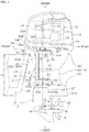
- Fig. 1 is a schematic left side view of an outboard motor 1 according to a preferred embodiment.
- the outboard motor 1 and a hull 2 to which the outboard motor 1 is attached define a vessel 3.
- Fig. 1 shows the outboard motor 1 in a reference posture.
- the reference posture is a posture of the outboard motor 1 in which a rotation axis 4A of a propeller 4 in the outboard motor 1 is along the horizontal direction and along a front-rear direction of the hull 2.
- the front-rear direction, the left-right direction, and the up-down direction in the following description correspond to the front-rear direction, the left-right direction, and the up-down direction when the outboard motor 1 is in the reference postu re.
- the outboard motor 1 includes an outboard motor main body 10 and an attaching mechanism 11.
- the outboard motor main body 10 is attached to a stern 2A of the hull 2 by the attaching mechanism 11.
- the outboard motor main body 10 includes the propeller 4 mentioned above, an engine cover 13, a casing 14, an engine 15, a drive shaft 16, a propeller shaft 17, and a gear mechanism 18.
- the engine cover 13 preferably has the shape of a box.
- the casing 14 is a hollow body extending downward from the engine cover 13.
- An upper end of the casing 14 is referred to as a mount plate 20
- a lower end of the casing 14 is referred to as a lower case 21, and a portion of the casing 14 between the mount plate 20 and the lower case 21 in the casing 14 is referred to as an upper case 22.
- a cavitation plate 21A projecting rearward is provided at an upper end of the lower case 21, a cavitation plate 21A projecting rearward is provided.
- the engine 15 is housed inside the engine cover 13, and mounted on the mount plate 20.
- the engine 15 is, for example an internal combustion engine that generates power by burning a fuel such as gasoline, and includes a combustion chamber 23, a crankshaft 24, and a piston 25.
- the crankshaft 24 has a crank axis 24A extending in the up-down direction.
- the piston 25 linearly reciprocates in the front-rear direction perpendicular to the crank axis 24A. Accordingly, the crankshaft 24 is driven to rotate around the crank axis 24A.
- the drive shaft 16 extends in the up-down direction inside the casing 14. An upper end of the drive shaft 16 is joined to a lower end of the crankshaft 24. A lower end of the drive shaft 16 is disposed inside the lower case 21. When the crankshaft 24 is driven to rotate, the drive shaft 16 rotates integrally with the crankshaft 24.
- the propeller shaft 17 is disposed inside the lower case 21, and disposed along the front-rear direction at a side lower than the lower end of the drive shaft 16.
- the gear mechanism 18 joins the lower end of the drive shaft 16 and the front end of the propeller shaft 17.
- the propeller 4 is located outside the lower case 21, and disposed directly below the cavitation plate 21A. Rotation of the drive shaft 16 due to driving of the engine 15 is transmitted to the propeller shaft 17 by the gear mechanism 18. Accordingly, the propeller 4 is driven to rotate by the engine 15.
- the rotation axis 4A of the propeller 4 corresponds to a central axis of the propeller shaft 17. Due to rotation of the propeller 4, a propulsive force to propel the hull 2 forward or backward is generated.
- the attaching mechanism 11 includes an attaching bracket 30, a swivel bracket 31, a tilt shaft 32, a steering shaft 33, an upper bracket 34, and a lower bracket 35.
- the attaching bracket 30 includes a left bracket 30L and a right bracket 30R disposed at an interval in the left-right direction.
- Each of the left bracket 30L and the right bracket 30R integrally includes a vertical portion 30A facing a rear surface of the stern 2A of the hull 2 from the rear side, and a horizontal portion 30B extending forward from an upper end of the vertical portion 30A and facing an upper end of the stern 2A from the upper side.
- Each of the left bracket 30L and the right bracket 30R is fixed to the stern 2A by a fastener 36 such as a bolt, for example (refer to Fig. 4A described below).
- a height dimension H between an intersection K of a front surface of the vertical portion 30A and a lower surface of the horizontal portion 30B, and a lower surface of the cavitation plate 21A may be referred to as a "transom height" or "shaft length.”
- the height dimension H differs depending on performance, etc., required for the outboard motor 1.
- the height dimension H may be increased.
- the height dimension H may be changed without using the extension 37.
- the swivel bracket 31 integrally includes an interposed portion 31A and a cylinder portion 31B provided at a rear end of the interposed portion 31A.
- the interposed portion 31A is disposed between the left bracket 30L and the right bracket 30R.
- the cylinder portion 31B preferably has a cylindrical or substantially cylindrical shape extending in the up-down direction.
- a tilt shaft 32 extends in the left-right direction and joins the interposed portion 31A to the left bracket 30L and the right bracket 30R. Accordingly, the swivel bracket 31 is enabled to turn up and down around the tilt shaft 32 with respect to the attaching bracket 30.
- the steering shaft 33 extends in the up-down direction and is inserted into the cylinder portion 31B.
- the steering shaft 33 is rotatable around a central axis of the steering shaft 33 with respect to the cylinder portion 31B.
- An upper end 33A of the steering shaft 33 projects upward from an upper end of the cylinder portion 31B, and a lower end 33B of the steering shaft 33 projects downward from a lower end of the cylinder portion 31B.
- the upper bracket 34 and the lower bracket 35 are examples of brackets that attach the outboard motor main body 10 to the hull 2.
- the upper bracket 34 is fixed to the upper end 33A of the steering shaft 33.
- the lower bracket 35 is located lower than the upper bracket 34 and fixed to the lower end 33B of the steering shaft 33.
- the outboard motor 1 includes pairs of anti-vibration mounts 40, each pair of which are provided for each of the upper bracket 34 and the lower bracket 35 and elastically support the outboard motor main body 10.
- the upper bracket 34 is joined to the mount plate 20 of the outboard motor main body 10 via one pair of anti-vibration mounts 40.
- the lower bracket 35 is joined to a lower portion of the upper case 22 of the outboard motor main body 10 via the other pair of anti-vibration mounts 40.
- the outboard motor main body 10 and the swivel bracket 31 are able to turn up and down around the tilt shaft 32 with respect to the attaching bracket 30.
- the outboard motor main body 10 is inclined with respect to the hull 2 and the attaching bracket 30.
- the outboard motor main body 10 is turnable in the left-right direction together with the steering shaft 33 with respect to the attaching bracket 30 and the swivel bracket 31.
- a plurality of kinds of outboard motors 1 may be present according to differences in the structure of the lower case 21 and the propeller 4, etc., although the engine 15 is common.
- the engine 15 is common.
- a projection projecting forward is provided to reduce water resistance.
- a large-diameter propeller 4 is used.
- two propellers 4 that rotate reversely to each other are disposed coaxially.
- FIG. 2 is a schematic perspective view showing the steering shaft 33, the upper bracket 34, the lower bracket 35, and the anti-vibration mounts 40 being a portion of a structure that attach the outboard motor main body 10 to the hull 2.
- Fig. 2 an exploded perspective view of one anti-vibration mount 40 is shown.
- the upper bracket 34 integrally includes a main body 34A, a pair of projections 34B, and a lever 34C.
- the main body 34A preferably has the shape of, for example, a block.
- an insertion hole 34D is provided into which the upper end 33A of the steering shaft 33 is inserted from below.
- Each of the pair of projections 34B preferably has, for example, a columnar shape.
- the pair of projections 34B are disposed side by side in the left-right direction, and project rearward from the main body 34A.
- the pair of projections 34B may extend parallel to each other, or may be disposed so that a distance between them increases toward the rear side as shown in Fig. 2 .
- the pair of projections 34B may be disposed along the horizontal direction, or may be inclined with respect to the horizontal direction.
- a screw hole 34E extending forward from a rear end surface of the projection 34B is provided (refer to Fig. 4A ).
- the lever 34C extends forward from, for example, a portion farther frontward than the insertion hole 34D on an upper surface of the main body 34A.
- the lower bracket 35 integrally includes a main body 35A and a pair of projections 35B.
- the main body portion 35A preferably has the shape of, for example, a block.
- an insertion hole 35C is provided into which the lower end portion 33B of the steering shaft 33 is inserted from above.
- Each of the pair of projections 35B preferably has, for example, a columnar shape.
- the pair of projections 35B are disposed side by side in the left-right direction, and project rearward from the main body 35A.
- the pair of projections 35B may extend parallel to each other, or may be disposed so that a distance between them increases toward the rear side as shown in Fig. 2 .
- the pair of projections 35B may be disposed along the horizontal direction, or may be inclined with respect to the horizontal direction.
- a screw hole (not shown) extending forward from a rear end surface of the projection 35B is provided.
- a pair of anti-vibration mounts 40 are provided for the pair of projections 34B in the upper bracket 34, and another pair of anti-vibration mounts 40 are provided for the pair of projections 35B in the lower bracket 35. That is, the outboard motor 1 includes a plurality (for example, two) of pairs of anti-vibration mounts 40. The two pairs of anti-vibration mounts 40 are spaced apart in the up-down direction according to the vertical positional relationship between the upper bracket 34 and the lower bracket 35.
- the pair of anti-vibration mounts 40 for the upper bracket 34 are referred to as a pair of upper anti-vibration mounts 40A, and the other pair of anti-vibration mounts 40 for the lower bracket 35 are referred to as a pair of lower anti-vibration mounts 40B.
- Each anti-vibration mount 40 includes a shaft 41, an elastic portion 42, an outer cylinder portion 43, and a fastener 44. It is noted that the outer cylinder portion 43 is fixed to the casing 14 of the outboard motor main body 10 as described below, so that the outer cylinder portion 43 may be regarded as not a portion of the anti-vibration mount 40 but a portion of the casing 14.
- the shaft 41 preferably has a circular or substantially circular tube shape and is made of, for example, a metal such as aluminum.
- a front end surface of the shaft 41 in each of the pair of upper anti-vibration mounts 40A abuts against a rear end surface of any projection 34B of the upper bracket 34 from the rear side, and this shaft 41 is disposed coaxially with the projection 34B.
- the shaft 41 in each of the pair of upper anti-vibration mounts 40A extends rearward from the upper bracket 34.
- a front end surface of the shaft 41 in each of the pair of lower anti-vibration mounts 40B abuts against a rear end surface of any projection 35B of the lower bracket 35 from the rear side, and this shaft 41 is disposed coaxially with the projection 35B.
- the shaft 41 in each of the pair of lower anti-vibration mounts 40B extends rearward from the lower bracket 35.
- the elastic portion 42 preferably has a cylindrical shape and is made of an elastic material such as rubber or sponge.
- the elastic portion 42 has a cylindrical shape having an inner diameter equal or substantially equal to an outer diameter of the shaft 41, and attached coaxially to the shaft 41 and surrounds the shaft 41.
- the shaft 41 is larger than the elastic portion 42. Therefore, both end portions of the shaft 41 in the axial direction X protrude from the elastic portion 42.
- a front end surface and a rear end surface of the elastic portion 42 surrounding the shaft 41 may include flat surfaces perpendicular or substantially perpendicular to the axial direction X, or may include curved surfaces.
- a section of an outer circumferential surface of the elastic portion 42 may not be circular, and may be rectangular, for example.
- the outer cylinder portion 43 has a cylindrical shape slightly larger than the elastic portion 42 and is made of, for example, a metal such as aluminum.
- the outer cylinder portion 43 has a cylindrical shape having an inner diameter equal or substantially equal to an outer diameter of the elastic portion 42, attached coaxially to the elastic portion 42, and surrounds the elastic portion 42.
- the outer cylinder portion 43 is larger than the elastic portion 42. Therefore, both end portions of the outer cylinder portion 43 in the axial direction X protrude from the elastic portion 42.
- the outer cylinder portion 43 is not in contact with the shaft 41.
- the elastic portion 42 may be always compressed between the shaft 41 and the outer cylinder portion 43.
- the fastener 44 is, for example, a bolt, and is inserted to the inside of the shaft 41 from the rear side.
- a front end of the fastener 44 includes a tip end 44A that is threaded.
- the tip end 44A is fitted into the screw hole 34E of the projection 34B in the upper bracket 34, and the shaft 41 is sandwiched between a head 44B at the rear end of the fastener 44 and the projection 34B (refer to Fig. 4A ). Accordingly, each of the pair of upper anti-vibration mounts 40A is joined to any projection 34B in the upper bracket 34.
- each of the pair of lower anti-vibration mounts 40B the tip end 44A of the fastener 44 is fitted into the screw hole (not shown) of the projection 35B in the lower bracket 35, and the shaft 41 is sandwiched between the head 44B of the fastener 44 and the projection 35B. Accordingly, each of the pair of lower anti-vibration mounts 40B is joined to any projection 35B in the lower bracket 35.
- the pair of upper anti-vibration mounts 40A are arranged side by side in the left-right direction.
- the pair of lower anti-vibration mounts 40B are arranged side by side in the left-right direction.
- their axial directions X may extend parallel to each other, or may extend so as to separate in the left-right direction toward the rear side as shown in Fig. 2 .
- their axial directions X may extend parallel to each other, or may extend so as to separate in the left-right direction toward the rear side as shown in Fig. 2 .
- the axial direction X of each anti-vibration mount 40 may be along the horizontal direction, or may be inclined with respect to the horizontal direction.
- accommodation portions 14 that accommodate a portion of the outer cylinder portions 43 of the respective anti-vibration mounts 40 are provided.
- An example of the accommodation portion 14A is a recessed portion recessed from the surface of the casing 14.
- Each of the accommodation portions 14A for the upper anti-vibration mounts 40A is provided in each of, for example, front regions of left and right both side surfaces of the mount plate 20.
- Each of the accommodation portions 14A for the lower anti-vibration mounts 40B is provided in each of, for example, front regions of the left and right both side surfaces of the lower end of the upper case 22.
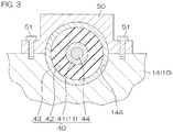
- Fig. 3 is a sectional view showing a cross section taken along line III-III in Fig. 1 .
- the outboard motor main body 10 further includes fixing members 50 to fix the outer cylinder portions 43 accommodated in the accommodation portions 14A to the casing 14.
- the fixing member 50 preferably has the shape of, for example, a cover, and covers a portion of the outer cylinder portion 43 protruding from the accommodation portion 14A.
- the fixing member 50 in this state is fixed to the casing 14 by a fastener 51 such as a bolt, for example.
- the outer cylinder portion 43 is fixed to the casing 14 while being sandwiched by the fixing member 50 and the casing 14.
- the elastic portion 42 is joined to the casing 14, that is, the outboard motor main body 10 via the outer cylinder portion 43.
- each anti-vibration mount 40 the elastic portion 42 interposed between the shaft 41 on the attaching mechanism 11 side and the outer cylinder portion 43 on the outboard motor main body 10 side is elastically deformable. Therefore, the outboard motor main body 10 is elastically supported by the pair of upper anti-vibration mounts 40A and the pair of lower anti-vibration mounts 40B (refer to Fig. 1 ).
- the pair of upper anti-vibration mounts 40A sandwich the mount plate 20 of the outboard motor main body 10 from the left and the right of the outboard motor main body 10 and elastically support the mount plate 20 (refer to Fig. 4A ).
- the pair of lower anti-vibration mounts 40B sandwich the lower end of the upper case 22 of the outboard motor main body 10 from the left and the right and elastically support this lower end. Since vibration of the outboard motor main body 10 is attenuated by elastic deformation of the elastic portion 42 in each of the pair of anti-vibration mounts 40 transmission of the vibration of the outboard motor main body 10 to the hull 2 is reduced.
- each anti-vibration mount 40 is disposed directly below the engine 15 so as to overlap the engine 15 in a planar view (refer to Fig. 5 described below). Therefore, each anti-vibration mount 40 does not need to be long enough to be disposed outside the engine 15 in the left-right direction in a planar view. If each anti-vibration mount 40 is long, to secure its strength, the support member such as the upper bracket 34 (in particular, the projection 34B of the upper bracket 34) that supports the anti-vibration mount 40 needs to be made larger, and the outboard motor main body 10 is increased in width in the left-right direction.
- the anti-vibration mount 40 at least a portion of which is disposed directly below the engine 15 as in the case of the present preferred embodiment, without increasing the size of the support member, the strength to support the outboard motor main body 10 is secured. In addition, it is also possible to reduce the width of the outboard motor main body 10 in the left-right direction around the engine 15.
- the outer cylinder portions 43 of the pair of upper anti-vibration mounts 40A may be fixed to the casing 14 by one fixing member 50.
- the upper anti-vibration mounts 40A and the lower anti-vibration mounts 40B may not be structurally the same.
- the structure to join the anti-vibration mount 40 to the outboard motor main body 10 such as the accommodation portion 14A and the fixing member 50 described above may differ from each other between the upper anti-vibration mounts 40A and the lower anti-vibration mounts 40B.
- Fig. 4A is a schematic plan view of the stern 2A of the hull 2 and the outboard motor 1.
- planar cross sections of a portion of the upper bracket 34 and the pair of upper anti-vibration mounts 40A are also shown.
- the pair of upper anti-vibration mounts 40A are described, and the following structure is also applicable to the pair of lower anti-vibration mounts 40B.
- the pair of upper anti-vibration mounts 40A arranged side by side in the left-right direction are disposed in a substantially V shape so as to separate in the left-right direction toward the rear side. Therefore, when the central axes J of the pair of upper anti-vibration mounts 40A are extended forward along their respective axial directions X, these central axes J cross each other in a planar view.
- a straight line L connecting the intersection K of these central axes J and the center P of the steering shaft 33 (turning center of the outboard motor main body 10 in a planar view) is along the front-rear direction.
- the straight line L is a centerline passing through the center of the outboard motor main body 10 in the left-right direction.
- the intersection K may be located farther frontward than the center P, may be located farther rearward than the center P, or may correspond to the center P.
- the crank axis 24A of the crankshaft 24 of the engine 15 is located farther rearward than the intersection K and the center P in a planar view, and disposed on the straight line L.
- the left upper anti-vibration mount 40A is referred to as an upper anti-vibration mount 40AL
- the right upper anti-vibration mount 40A is referred to as an upper anti-vibration mount 40AR.
- the axial direction X of the central axis J of the upper anti-vibration mount 40AL may be referred to as an axial direction XL
- the axial direction X of the central axis J of the upper anti-vibration mount 40AR may be referred to as an axial direction XR.
- a contour R of the outboard motor main body 10 in a stopped state in a planar view is shown by an alternate long and short dashed line.
- the outboard motor 1 is activated, according to driving of the engine 15 and/or driving rotation of the propeller 4, the outboard motor main body 10 rolls.
- the outboard motor main body 10 reciprocates along a circumferential direction S around a predetermined center Q in a planar view.
- This center Q is a center of rolling of the outboard motor main body 10. Due to rolling, the contour R of the outboard motor main body 10 wiggles in the left-right direction as shown by the alternate long and short dashed line and the alternate long and two short dashed line.
- the center Q is located farther rearward than the intersection K and the center P on the inner side of the contour R, and disposed on the straight line L, by way of example, in a planar view.
- the center Q may be disposed farther rearward than the crank axis 24A. While the outboard motor 1 is activated, the location of the center Q fluctuates within a predetermined range on the straight line L.
- the location of the center Q in the front-rear direction differs depending on a difference in the kind of the outboard motor 1, that is, for example, a difference in the shape of the lower case 21, a difference in the structure of the propeller 4, a difference in the height dimension H, or a difference in the vertical distance between the upper anti-vibration mount 40A and the lower anti-vibration mount 40B, etc.
- the location of the center Q in the front-rear direction differs.
- a location of a point G of application of water pressure being a location to which a water pressure is applied in the lower case 21 when traveling forward changes.
- a location of a point M of application of reaction force being a location to which a reaction force generated by rotation of the propeller 4 is applied in the lower case 21 changes.
- a location of a point N of application of a total load on the lower case 21 changes.
- the point N of application is located on a line segment B connecting the point G of application of water pressure and the point M of application of reaction force.
- the location of the center Q of rolling in the front-rear direction changes.
- the center Q on the straight line L is located, as shown in Fig.
- the center Q is present in a region 60 sandwiched by the central axes J of the pair of upper anti-vibration mounts 40A in a planar view, and in particular, located at a central portion close to the straight line L in the region 60.
- the location of the center Q fluctuates according to a difference in the kind of the outboard motor 1 and a situation of the outboard motor 1 during activation, etc., described above, therefore, the center Q is not necessarily located on the straight line L although it is present at the central portion (near the straight line L) of the region 60.
- a location at which a force from the outboard motor main body 10 is applied to the elastic portion 42 when rolling occurs is referred to as an application location V.
- the application location V is defined in a boundary portion between the elastic portion 42 and the outer cylinder portion 43.
- the application location V is set, on a region 42A facing the outboard motor main body 10 on an outer circumferential surface of each elastic portion 42, to a center of the region 42A in the axial direction X, by way of example.
- the pair of upper anti-vibration mounts 40A are bilaterally asymmetrical to each other about the straight line L and the center P of the steering shaft 33.
- the location of the elastic portion 42 in the front-rear direction differs from each other between the pair of upper anti-vibration mounts 40A so that the location of the elastic portion 42 is displaced farther rearward in the upper anti-vibration mount 40AR than in the upper anti-vibration mount 40AL.
- the application location V in the elastic portion 42 differs from each other between the pair of upper anti-vibration mounts 40A in the front-rear direction so that the application location V is displaced farther rearward in the upper anti-vibration mount 40AR than in the upper anti-vibration mount 40AL.
- the direction distance D differs from each other between the pair of upper anti-vibration mounts 40A.
- the direct distance DL in the upper anti-vibration mount 40AL is shorter than the direct distance DR in the upper anti-vibration mount 40AR.
- a rigidity in a perpendicular direction Y which is perpendicular to the axial direction X of the shaft 41 is higher than a rigidity in the axial direction X.
- the shaft 41 and the cylindrical elastic portion 42 surrounding the shaft 41 are arranged side by side in the perpendicular direction Y, so that in the elastic portion 42, at the application location V, a deformation amount when a force in the perpendicular direction Y is applied is small, and a deformation amount when a force in the axial direction X is applied is large. That is, the elastic portion 42 is soft in the axial direction X, and hard in the perpendicular direction Y.
- a circumferential direction S passing through the application location V of the upper anti-vibration mount 40AL is referred to as a circumferential direction SL
- a circumferential direction S passing through the application location V of the upper anti-vibration mount 40AR is referred to as a circumferential direction SR
- a tangential direction T with respect to the circumferential direction SL is referred to as a tangential direction TL
- a tangential direction T with respect to the circumferential direction SR is referred to as a tangential direction TR.
- both upper anti-vibration mounts 40A are bilaterally symmetrical as shown in Fig. 4B .
- a force from the outboard motor main body 10 when rolling occurs is equally applied to the upper anti-vibration mounts 40AL and 40AR that are bilaterally symmetrical.
- the axial direction X and the tangential direction T in each upper anti-vibration mount 40A become parallel to each other in a planar view in some cases.
- the pair of upper anti-vibration mounts 40A are bilaterally asymmetrical to each other.
- the axial direction X of the shaft 41 in at least one of the upper anti-vibration mounts 40A and the tangential direction T with respect to the circumferential direction S at the application location V of the elastic portion 42 of this upper anti-vibration mount 40A cross each other in a planar view.
- a crossing angle ⁇ between a straight line C connecting the center Q and the application location V and the axial direction X in a planar view becomes a value different from 90 degrees.
- a length of the straight line CL connecting the center Q and the application location V of the upper anti-vibration mount 40AL and a length of the straight line CR connecting the center Q and the application location V of the upper anti-vibration mount 40AR are different from each other. Therefore, the circumferential direction SL and the circumferential direction SR are not located on the same circumference.
- At least one upper anti-vibration mount 40A positioned so that the axial direction X and the tangential direction T crosses each other in a planar view, a force from the outboard motor main body 10 when rolling occurs is not biased only in the axial direction X, but is distributed in both of the axial direction X and the perpendicular direction Y and applied to the elastic portion 42. Therefore, at least this one upper anti-vibration mount 40A receives a force from the outboard motor main body 10 in the perpendicular direction Y as well in which the rigidity is high, and accordingly, the elastic deformation amount of the elastic portion 42 is reduced. As in the case of Fig.
- the above-described crossing angle ⁇ differs from each other between the pair of upper anti-vibration mounts 40A.
- a crossing angle ⁇ L between the straight line CL and the axial direction XL in the upper anti-vibration mount 40AL and a crossing angle ⁇ R between the straight line CR and the axial direction XR in the upper anti-vibration mount 40AR are different from each other. Accordingly, the pair of upper anti-vibration mounts 40A are bilaterally asymmetrical to each other.
- the manner of receiving a force by the upper anti-vibration mount 40A differs from each other between the pair of upper anti-vibration mounts 40A.
- the axial direction X and the tangential direction T become parallel to each other in a planar view in one upper anti-vibration mount 40A according to forward and rearward movement of the center Q of rolling, the axial direction X and the tangential direction T in the other upper anti-vibration mount 40A always cross each other in a planar view.
- both upper anti-vibration mounts 40A do not equally elastically deform, and the other upper anti-vibration mount 40A is able to bear a load in the perpendicular direction Y in which the rigidity is high.
- the elastic deformation amount of the elastic portion 42 in at least one upper anti-vibration mount 40A is reduced, even if a location of the center Q in the front-rear direction differs depending on the kind of the outboard motor 1, rolling of the outboard motor main body 10 is reduced.
- the upper anti-vibration mount 40AL is a first upper anti-vibration mount 40A positioned upstream in the direction of application of the reaction force F.
- the application location V to which a force from the outboard motor main body 10 is applied in the upper anti-vibration mount 40AL when rolling occurs is preferably disposed farther apart forward from the center Q of rolling than the application location V in the other (second) upper anti-vibration mount 40AR.
- the straight line CL connecting the center Q and the application location V in the upper anti-vibration mount AL is longer in the front-rear direction than the straight line CR in the upper anti-vibration mount 40AR.
- the pair of upper anti-vibration mounts 40A are bilaterally asymmetrical to each other.
- the upper anti-vibration mount 40AL receives a force from the outboard motor main body 10 at a location distant from the center Q of rolling. Accordingly, the upper anti-vibration mount 40AL is less influenced by the reaction force F according to "the principle of leverage" using the center Q of rolling as a fulcrum. Therefore, the upper anti-vibration mount 40AL attenuates vibration of the outboard motor main body 10 by absorbing the force from the outboard motor main body 10 by a small elastic deformation amount. Accordingly, the elastic deformation amount in the upper anti-vibration mount 40AL is reduced, therefore, rolling of the outboard motor main body 10 is reduced.
- the shaft 41 which serves as a core may be omitted and the elastic portion 42 may be solid.
- Fig. 5 is a schematic plan view of a portion of the hull 2 and an outboard motor 1 according to the first modification.
- the shafts 41, the outer cylinder portions 43, and the fasteners 44 may be bilaterally symmetrical by respectively having the same shape, the same dimensions, and the same layout.
- at least the elastic portions 42 are arranged differently so as to become bilaterally asymmetrical to each other between the pair of upper anti-vibration mounts 40A.
- the direct distance E from the above-described intersection K to the elastic portion 42 differs from each other between the pair of upper anti-vibration mounts 40A.
- the direct distance E (referred to as a direct distance EL) is relatively short, so that the elastic portion 42 surrounds a front end of the shaft 41 close to the intersection K.
- the direct distance E (referred to as a direct distance ER) is relatively long, so that the elastic portion 42 surrounds a rear end of the shaft 41 distant from the intersection K.
- the direct distance ER is longer than the direct distance EL.
- the location of the elastic portion 42 in the front-rear direction differs from each other between the pair of upper anti-vibration mounts 40A. Accordingly, in at least one anti-vibration mount 40, the axial direction X of the shaft 41 and the tangential direction T at the application location V cross each other in a planar view. Therefore, by reducing an elastic deformation amount of the elastic portion 42 of at least one of the anti-vibration mounts 40, rolling of the outboard motor main body 10 is reduced.
- the pair of upper anti-vibration mounts 40A include common components, and the location of the elastic portion 42 in the front-rear direction is made to differ from each other between the pair of upper anti-vibration mounts 40A.
- Fig. 6 is a schematic perspective view of an anti-vibration mount 40 in an outboard motor 1 according to the second modification.
- the second modification only one end surface 42B of both end surfaces of the elastic portion 42 in the axial direction X is inclined with respect to the axial direction X.
- a cut-away portion 42C is provided by, for example, cutting away a portion in the circumferential direction W around the shaft 41.
- the cut-away portion 42C is provided by diagonally cutting away almost the entire region of the end surface 42B except for a portion on the circumference, however, the shape of the cut-away portion 42C may be arbitrarily changed.
- Fig. 7 is a schematic plan view of a portion of the hull 2 and the outboard motor 1 according to the second modification.
- the location of the cut-away portion 42C in the front-rear direction differs from each other between the pair of upper anti-vibration mounts 40A.
- the cut-away portion 42C of the upper anti-vibration mount 40AL is displaced rearward relative to the cut-away portion 42C of the upper anti-vibration mount 40AR. Accordingly, the pair of upper anti-vibration mounts 40A are bilaterally asymmetrical to each other, therefore, rolling of the outboard motor main body 10 is reduced.
- the application location V in the elastic portion 42 preferably differ from each other between the pair of upper anti-vibration mounts 40A in the front-rear direction. Accordingly, in at least one of the anti-vibration mounts 40, the axial direction X of the shaft 41 and the tangential direction T at the application location V cross each other in a planar view.
- Fig. 8 is a schematic exploded perspective view of an anti-vibration mount 40 in an outboard motor 1 according to the third modification.
- the third modification in the elastic portion 42, for example, in a portion between the region 42A and the shaft 41, an insertion hole 42D extending in the axial direction X and penetrating through the elastic portion 42 is provided.
- Each of the pair of upper anti-vibration mounts 40A further includes an insertion member 45.
- the insertion member 45 is preferably made of a material (for example, resin or hard rubber such as urethane) harder than the elastic portion 42, and integrally includes a base 45A and an insertion portion 45B.
- the base 45A preferably has an annular or substantially annular shape having a central axis extending along the axial direction X.
- the insertion portion 45B projects from one point on the circumference of the base 45A and extends in the axial direction X. In terms of a dimension in the axial direction X, the insertion portion 45B is smaller than the insertion hole 42D.
- the insertion member 45 is fitted to the shaft 41 and the elastic portion 42 from the axial direction X. In the insertion member 45 after fitting, the base 45A surrounds the shaft 41, and the insertion portion 45B is inserted in the insertion hole 42D.
- Fig. 9 is a schematic plan view of a portion of the hull 2 and the outboard motor 1 according to the third modification.
- the position of the insertion portion 45B in the insertion hole 42D differs from each other between the pair of upper anti-vibration mounts 40A.
- the insertion member 45 in the upper anti-vibration mount 40AL, the insertion member 45 is fitted to the shaft 41 and the elastic portion 42 from the rear side, and in the upper anti-vibration mount 40AR, the insertion member 45 is fitted to the shaft 41 and the elastic portion 42 from the front side. Therefore, the insertion portion 45B of the upper anti-vibration mount 40AR is displaced forward relative to the insertion portion 45B of the upper anti-vibration mount 40AL.
- the portion at the same position as the insertion portion 45B in the axial direction X is reinforced by the insertion portion 45B and accordingly hardly deforms in the perpendicular direction Y. Therefore, in the elastic portion 42 of the upper anti-vibration mount 40AL, rigidity in the perpendicular direction Y of a rear portion 42E at the same position as the insertion portion 45B in the axial direction X is higher than a rigidity in the perpendicular direction Y of a front portion 42F displaced from the insertion portion 45B.
- a rigidity in the perpendicular direction Y of the front portion 42F at the same position as the insertion portion 45B in the axial direction X is higher than a rigidity in the perpendicular direction Y of the rear portion 42E displaced from the insertion portion 45B.
- the application location V is set at the rear portion 42E. Therefore, a rigidity in the perpendicular direction Y of a portion of the elastic portion 42 to which a force from the outboard motor main body 10 is applied when rolling occurs differs from each other between the pair of upper anti-vibration mounts 40A. Accordingly, the pair of upper anti-vibration mounts 40A are bilaterally asymmetrical to each other, therefore, rolling of the outboard motor main body 10 is reduced.
- the application location V in each of the pair of upper anti-vibration mounts 40A, the application location V may be set to the same location as the insertion portion 45B in the axial direction X.
- a rigidity of a portion of the elastic portion 42 to which a force from the outboard motor main body 10 is applied is the same between the pair of upper anti-vibration mounts 40A, however, the application location V in the front-rear direction differs from each other between the pair of upper anti-vibration mounts 40A.
- the axial direction X of the shaft 41 and the tangential direction T at the application location V cross each other in a planar view.
- an application location V may also be set in a region (for example, an outer region 42G located opposite to the region 42A in the left-right direction) other than the above-described region 42A.
- a region for example, an outer region 42G located opposite to the region 42A in the left-right direction
- the above-described structure that makes the pair of anti-vibration mounts 40 bilaterally asymmetrical to each other may also be applied.
- the elastic portion 42 a portion that does not elastically deform, that is, a portion that does not contribute to attenuation of vibration of the outboard motor main body 10 may be omitted.
- the elastic portion 42 in this case may not be cylindrical, and is required to be provided in at least a portion of the outer circumferential surface of the shaft 41 facing the outboard motor main body 10.
Landscapes
- Engineering & Computer Science (AREA)
- Chemical & Material Sciences (AREA)
- Combustion & Propulsion (AREA)
- Mechanical Engineering (AREA)
- Ocean & Marine Engineering (AREA)
- General Engineering & Computer Science (AREA)
- Vibration Prevention Devices (AREA)
- Springs (AREA)
Description
- The present invention relates to an outboard motor and a vessel.
- An outboard motor main body of an outboard motor described in the specification of
U.S. Patent No. 7,896,304 is attached to a hull via a transom bracket and a steering bracket. The transom bracket supports the steering bracket turnably around a vertically extending steering axis. The steering bracket supports a pair of mounts. These mounts are configured bilaterally symmetrically about the steering axis. Each mount includes a rod to be fitted to the steering bracket, a tube to be fitted to the outboard motor main body while surrounding the rod, and an elastomer disposed between the rod and the tube. Due to elastic deformation of the elastomer, transmission of vibration of the outboard motor main body to the hull is suppressed. - An outboard motor main body of an outboard motor described in Japanese Patent Application Publication No.
2001-88787 - As described in
U.S. Patent No. 7,896,304 and Japanese Patent Application Publication No.2001-88787 - It is an object of the present invention to provide an outboard motor and a vessel having compact structure an suitable appearance. According to the present invention said object is solved by an outboard motor having the features of
independent claim 1. Moreover, said object is solved by a vessel according to claim 12. Preferred embodiments are laid down in the dependent claims. Accordingly, a preferred embodiment provides an outboard motor including an outboard motor main body that includes an engine and a propeller driven by the engine, a bracket to attach the outboard motor main body to a hull, and a pair of anti-vibration mounts. The pair of anti-vibration mounts are joined to the bracket and sandwich and elastically support a portion of the outboard motor main body from the left and the right of the outboard motor main body. The pair of anti-vibration mounts are arranged side by side in the left-right direction so that a center of rolling of the outboard motor main body is located between the pair of anti-vibration mounts in the left-right direction, and are bilaterally asymmetrical to each other. - According to this preferred embodiment, due to respective elastic deformation of the pair of anti-vibration mounts, vibration of the outboard motor main body is attenuated, so that transmission of the vibration of the outboard motor main body to the hull is reduced. The pair of anti-vibration mounts are bilaterally asymmetrical to each other so that the manner in which the application of a force to the anti-vibration mounts from the outboard motor main body when rolling caused by vibration differs from each other between the pair of anti-vibration mounts. That is, the manner of receiving a force by the anti-vibration mounts differs from each other between the pair of anti-vibration mounts. Accordingly, the anti-vibration mounts do not elastically deform in the same way, so that an elastic deformation amount in at least one anti-vibration mount is reduced. Therefore, rolling of the outboard motor main body is reduced.
- In a preferred embodiment, each of the pair of anti-vibration mounts preferably includes a shaft extending rearward from the bracket, and an elastic portion that has a cylindrical or substantially cylindrical shape (hereafter "cylindrical shape") surrounding the shaft and joined to the outboard motor main body.
- In this case, in at least one of the anti-vibration mounts, an axial direction of the shaft and a tangential direction with respect to a circumferential direction around a center of rolling at a location in the elastic portion to which a force from the outboard motor main body is applied when the rolling occurs cross each other in a planar view.
- According to this preferred embodiment, in each anti-vibration mount, due to elastic deformation of the elastic portion surrounding the shaft, vibration of the outboard motor main body is attenuated. The elastic portion preferably has a cylindrical shape surrounding the shaft, so that a rigidity of the elastic portion in a perpendicular direction perpendicular to the axial direction of the shaft is higher than a rigidity of the elastic portion in the axial direction.
- In both anti-vibration mounts, it is assumed that the axial direction of the shaft and the tangential direction with respect to a circumferential direction around a center of rolling at a location in the elastic portion to which a force from the outboard motor main body is applied when the rolling occurs, are parallel to each other in a planar view. In this case, the force from the outboard motor main body when rolling occurs is applied to the elastic portion along the axial direction, so that the elastic portion largely deforms in the axial direction to attenuate vibration of the outboard motor main body. When the elastic portions of both anti-vibration mounts thus largely deform, the outboard motor main body greatly rolls.
- However, according to the present preferred embodiment, in at least one of the anti-vibration mounts, the axial direction of the shaft and the tangential direction cross each other in a planar view. Therefore, in at least this one of the anti-vibration mounts, the force from the outboard motor main body when rolling occurs is not biased only in the axial direction but is distributed in both of the axial direction and the perpendicular direction and applied to the elastic portion, so that an elastic deformation amount of the elastic portion is reduced. Accordingly, rolling of the outboard motor main body is reduced.
- In a preferred embodiment, a location in the elastic portion to which a force from the outboard motor main body is applied when rolling occurs preferably differs between the pair of anti-vibration mounts in the front-rear direction.
- According to this preferred embodiment, in at least one of the anti-vibration mounts, the axial direction of the shaft and the tangential direction cross each other in a planar view. Accordingly, by reducing an elastic deformation amount of the elastic portion of at least one of the anti-vibration mounts, rolling of the outboard motor main body is reduced.
- In a preferred embodiment, a location of the elastic portion in the front-rear direction preferably differs between the pair of anti-vibration mounts.
- According to this preferred embodiment, in at least one of the anti-vibration mounts, the axial direction of the shaft and the tangential direction cross each other in a planar view. Accordingly, by reducing an elastic deformation amount of the elastic portion of at least one of the anti-vibration mounts, rolling of the outboard motor main body is reduced.
- In a preferred embodiment, in the elastic portion, a cut-away portion is preferably provided in a portion extending in a circumferential direction around the shaft, and a location of the cut-away portion in the front-rear direction preferably differs between the pair of anti-vibration mounts.
- According to this preferred embodiment, the pair of anti-vibration mounts are bilaterally asymmetrical to each other and, therefore, by reducing an elastic deformation amount of the elastic portion of at least one of the anti-vibration mounts, rolling of the outboard motor main body is reduced.
- In a preferred embodiment, a rigidity of a portion of the elastic portion to which a force from the outboard motor main body is applied when rolling occurs preferably differs between the pair of anti-vibration mounts.
- According to this preferred embodiment, the pair of anti-vibration mounts are bilaterally asymmetrical to each other and, therefore, by reducing an elastic deformation amount of the elastic portion of at least one of the anti-vibration mounts, rolling of the outboard motor main body is reduced.
- In a preferred embodiment, an insertion hole extending in the axial direction of the shaft is preferably provided in the elastic portion, and each of the pair of anti-vibration mounts preferably further includes an insertion member to be inserted into the insertion hole. In this case, a position of the insertion member in the insertion hole differs between the pair of anti-vibration mounts.
- According to this preferred embodiment, the pair of anti-vibration mounts are bilaterally asymmetrical to each other and, therefore, by reducing an elastic deformation amount of the elastic portion of at least one of the anti-vibration mounts, rolling of the outboard motor main body is reduced.
- In a preferred embodiment, the pair of anti-vibration mounts includes a first anti-vibration mount positioned upstream in a direction in which a reaction force generated by rotation of the propeller is applied, a location to which a force from the outboard motor main body is applied when rolling occurs is preferably spaced farther apart from the center of rolling than a location in a second anti-vibration mount to which a force from the outboard motor main body is applied when rolling occurs.
- According to this preferred embodiment, when an influence of a reaction force generated by rotation of the propeller is a significant cause of rolling of the outboard motor main body, a proportion of this reaction force as a force to be applied from the outboard motor main body to the anti-vibration mount when rolling occurs is high. In this case, the first anti-vibration mount positioned upstream in an application direction of this reaction force receives a force from the outboard motor main body at a location distant from a center of the rolling. Accordingly, according to "the principle of leverage" using the center of rolling as a fulcrum, this first anti-vibration mount is less influenced by the reaction force. Therefore, due to a small elastic deformation amount of this first anti-vibration mount, the force from the outboard motor main body is absorbed and vibration of the outboard motor main body is attenuated. Therefore, since the elastic deformation amount in this first anti-vibration mount is reduced, rolling of the outboard motor main body is reduced.
- In a preferred embodiment, a plurality of pairs of anti-vibration mounts are preferably provided, and the plurality of pairs of anti-vibration mounts are preferably spaced apart in the up-down direction.
- According to this preferred embodiment, in each pair of anti-vibration mounts, an elastic deformation amount in at least one of the pair of anti-vibration mounts is reduced, therefore, rolling of the outboard motor main body is further reduced.
- In a preferred embodiment, at least a portion of the anti-vibration mount is preferably disposed directly below the engine.
- According to this preferred embodiment, the anti-vibration mount does not need to be long enough to be disposed outside the engine in a planar view. When the anti-vibration mount is long, to secure its strength, a support member such as a bracket to support the anti-vibration mount needs to be increased in size. However, in the case of the anti-vibration mount of this preferred embodiment, a strength to support the outboard motor main body is secured without increasing the size of the support member. In addition, at least a portion of the anti-vibration mount is disposed directly below the engine, so that a width of the outboard motor main body in the left-right direction around the engine is small.
- As described above, according to preferred embodiments, rolling of the outboard motor that is elastically supported is reduced.
- The above and other elements, features, steps, characteristics and advantages of the present invention will become more apparent from the following detailed description of the preferred embodiments with reference to the attached drawings.
-
-
Fig. 1 is a schematic left side view of an outboard motor according to a preferred embodiment. -
Fig. 2 is a schematic perspective view showing a structure in an outboard motor to attach an outboard motor main body to a hull. -
Fig. 3 is a sectional view showing a cross section taken along line III-III inFig. 1 . -
Fig. 4A is a schematic plan view of a portion of the hull and the outboard motor. -
Fig. 4B is a schematic plan view of a portion of the hull and an outboard motor according to a comparative example. -
Fig. 5 is a schematic plan view of a portion of the hull and an outboard motor according to a first modification of a preferred embodiment. -
Fig. 6 is a schematic perspective view of an anti-vibration mount in an outboard motor according to a second modification of a preferred embodiment. -
Fig. 7 is a schematic plan view of a portion of the hull and the outboard motor according to the second modification. -
Fig. 8 is a schematic exploded perspective view of an anti-vibration mount in an outboard motor according to a third modification of a preferred embodiment. -
Fig. 9 is a schematic plan view of a portion of the hull and the outboard motor according to the third modification. - Hereinafter, preferred embodiments are described in detail with reference to the accompanying drawings.
Fig. 1 is a schematic left side view of anoutboard motor 1 according to a preferred embodiment. Theoutboard motor 1 and ahull 2 to which theoutboard motor 1 is attached define avessel 3.Fig. 1 shows theoutboard motor 1 in a reference posture. The reference posture is a posture of theoutboard motor 1 in which arotation axis 4A of apropeller 4 in theoutboard motor 1 is along the horizontal direction and along a front-rear direction of thehull 2. The front-rear direction, the left-right direction, and the up-down direction in the following description correspond to the front-rear direction, the left-right direction, and the up-down direction when theoutboard motor 1 is in the reference postu re. - The
outboard motor 1 includes an outboard motormain body 10 and an attachingmechanism 11. The outboard motormain body 10 is attached to a stern 2A of thehull 2 by the attachingmechanism 11. The outboard motormain body 10 includes thepropeller 4 mentioned above, anengine cover 13, acasing 14, anengine 15, adrive shaft 16, apropeller shaft 17, and agear mechanism 18. - The
engine cover 13 preferably has the shape of a box. Thecasing 14 is a hollow body extending downward from theengine cover 13. An upper end of thecasing 14 is referred to as amount plate 20, a lower end of thecasing 14 is referred to as alower case 21, and a portion of thecasing 14 between themount plate 20 and thelower case 21 in thecasing 14 is referred to as anupper case 22. At an upper end of thelower case 21, acavitation plate 21A projecting rearward is provided. - The
engine 15 is housed inside theengine cover 13, and mounted on themount plate 20. Theengine 15 is, for example an internal combustion engine that generates power by burning a fuel such as gasoline, and includes acombustion chamber 23, acrankshaft 24, and apiston 25. Thecrankshaft 24 has acrank axis 24A extending in the up-down direction. By burning an air-fuel mixture inside thecombustion chamber 23, thepiston 25 linearly reciprocates in the front-rear direction perpendicular to the crankaxis 24A. Accordingly, thecrankshaft 24 is driven to rotate around thecrank axis 24A. - The
drive shaft 16 extends in the up-down direction inside thecasing 14. An upper end of thedrive shaft 16 is joined to a lower end of thecrankshaft 24. A lower end of thedrive shaft 16 is disposed inside thelower case 21. When thecrankshaft 24 is driven to rotate, thedrive shaft 16 rotates integrally with thecrankshaft 24. - The
propeller shaft 17 is disposed inside thelower case 21, and disposed along the front-rear direction at a side lower than the lower end of thedrive shaft 16. Thegear mechanism 18 joins the lower end of thedrive shaft 16 and the front end of thepropeller shaft 17. To a rear end of thepropeller shaft 17, thepropeller 4 is attached. Thepropeller 4 is located outside thelower case 21, and disposed directly below thecavitation plate 21A. Rotation of thedrive shaft 16 due to driving of theengine 15 is transmitted to thepropeller shaft 17 by thegear mechanism 18. Accordingly, thepropeller 4 is driven to rotate by theengine 15. Therotation axis 4A of thepropeller 4 corresponds to a central axis of thepropeller shaft 17. Due to rotation of thepropeller 4, a propulsive force to propel thehull 2 forward or backward is generated. - The attaching
mechanism 11 includes an attachingbracket 30, aswivel bracket 31, atilt shaft 32, a steeringshaft 33, anupper bracket 34, and alower bracket 35. - The attaching
bracket 30 includes aleft bracket 30L and aright bracket 30R disposed at an interval in the left-right direction. Each of theleft bracket 30L and theright bracket 30R integrally includes avertical portion 30A facing a rear surface of the stern 2A of thehull 2 from the rear side, and ahorizontal portion 30B extending forward from an upper end of thevertical portion 30A and facing an upper end of the stern 2A from the upper side. Each of theleft bracket 30L and theright bracket 30R is fixed to the stern 2A by afastener 36 such as a bolt, for example (refer toFig. 4A described below). A height dimension H between an intersection K of a front surface of thevertical portion 30A and a lower surface of thehorizontal portion 30B, and a lower surface of thecavitation plate 21A, may be referred to as a "transom height" or "shaft length." The height dimension H differs depending on performance, etc., required for theoutboard motor 1. By interposing anextension 37 between thelower case 21 and theupper case 22, the height dimension H may be increased. By changing the size of theupper case 22, the height dimension H may be changed without using theextension 37. - The
swivel bracket 31 integrally includes an interposedportion 31A and acylinder portion 31B provided at a rear end of the interposedportion 31A. The interposedportion 31A is disposed between theleft bracket 30L and theright bracket 30R. Thecylinder portion 31B preferably has a cylindrical or substantially cylindrical shape extending in the up-down direction. Atilt shaft 32 extends in the left-right direction and joins the interposedportion 31A to theleft bracket 30L and theright bracket 30R. Accordingly, theswivel bracket 31 is enabled to turn up and down around thetilt shaft 32 with respect to the attachingbracket 30. - The steering
shaft 33 extends in the up-down direction and is inserted into thecylinder portion 31B. The steeringshaft 33 is rotatable around a central axis of the steeringshaft 33 with respect to thecylinder portion 31B. Anupper end 33A of the steeringshaft 33 projects upward from an upper end of thecylinder portion 31B, and alower end 33B of the steeringshaft 33 projects downward from a lower end of thecylinder portion 31B. - The
upper bracket 34 and thelower bracket 35 are examples of brackets that attach the outboard motormain body 10 to thehull 2. Theupper bracket 34 is fixed to theupper end 33A of the steeringshaft 33. Thelower bracket 35 is located lower than theupper bracket 34 and fixed to thelower end 33B of the steeringshaft 33. Theoutboard motor 1 includes pairs of anti-vibration mounts 40, each pair of which are provided for each of theupper bracket 34 and thelower bracket 35 and elastically support the outboard motormain body 10. Theupper bracket 34 is joined to themount plate 20 of the outboard motormain body 10 via one pair of anti-vibration mounts 40. Thelower bracket 35 is joined to a lower portion of theupper case 22 of the outboard motormain body 10 via the other pair of anti-vibration mounts 40. - The outboard motor
main body 10 and theswivel bracket 31 are able to turn up and down around thetilt shaft 32 with respect to the attachingbracket 30. By turning the outboard motormain body 10 around thetilt shaft 32, the outboard motormain body 10 is inclined with respect to thehull 2 and the attachingbracket 30. The outboard motormain body 10 is turnable in the left-right direction together with the steeringshaft 33 with respect to the attachingbracket 30 and theswivel bracket 31. - A plurality of kinds of
outboard motors 1 may be present according to differences in the structure of thelower case 21 and thepropeller 4, etc., although theengine 15 is common. For example, in the case of anoutboard motor 1 for a high-speed boat, at a front end portion of thelower case 21, a projection projecting forward is provided to reduce water resistance. In the case of anoutboard motor 1 for high loads, a large-diameter propeller 4 is used. When acceleration of thevessel 3 is important, twopropellers 4 that rotate reversely to each other are disposed coaxially. - Next, the
upper bracket 34, thelower bracket 35, and the anti-vibration mounts 40 are described in detail.Fig. 2 is a schematic perspective view showing the steeringshaft 33, theupper bracket 34, thelower bracket 35, and the anti-vibration mounts 40 being a portion of a structure that attach the outboard motormain body 10 to thehull 2. InFig. 2 , an exploded perspective view of oneanti-vibration mount 40 is shown. - The
upper bracket 34 integrally includes amain body 34A, a pair ofprojections 34B, and alever 34C. Themain body 34A preferably has the shape of, for example, a block. At a center of themain body 34A in a planar view, aninsertion hole 34D is provided into which theupper end 33A of the steeringshaft 33 is inserted from below. Each of the pair ofprojections 34B preferably has, for example, a columnar shape. The pair ofprojections 34B are disposed side by side in the left-right direction, and project rearward from themain body 34A. The pair ofprojections 34B may extend parallel to each other, or may be disposed so that a distance between them increases toward the rear side as shown inFig. 2 . The pair ofprojections 34B may be disposed along the horizontal direction, or may be inclined with respect to the horizontal direction. In eachprojection 34B, ascrew hole 34E extending forward from a rear end surface of theprojection 34B is provided (refer toFig. 4A ). Thelever 34C extends forward from, for example, a portion farther frontward than theinsertion hole 34D on an upper surface of themain body 34A. When a vessel operator holds thelever 34C and moves it to the left or right, or thelever 34C is moved to the left or right by an electric steering device (not shown), the outboard motormain body 10 turns in the left-right direction together with the steeringshaft 33, so that thevessel 3 is steered. - The
lower bracket 35 integrally includes amain body 35A and a pair ofprojections 35B. Themain body portion 35A preferably has the shape of, for example, a block. At the center of themain body 35A in a planar view, aninsertion hole 35C is provided into which thelower end portion 33B of the steeringshaft 33 is inserted from above. Each of the pair ofprojections 35B preferably has, for example, a columnar shape. The pair ofprojections 35B are disposed side by side in the left-right direction, and project rearward from themain body 35A. The pair ofprojections 35B may extend parallel to each other, or may be disposed so that a distance between them increases toward the rear side as shown inFig. 2 . The pair ofprojections 35B may be disposed along the horizontal direction, or may be inclined with respect to the horizontal direction. In eachprojection 35B, a screw hole (not shown) extending forward from a rear end surface of theprojection 35B is provided. - A pair of anti-vibration mounts 40 are provided for the pair of
projections 34B in theupper bracket 34, and another pair of anti-vibration mounts 40 are provided for the pair ofprojections 35B in thelower bracket 35. That is, theoutboard motor 1 includes a plurality (for example, two) of pairs of anti-vibration mounts 40. The two pairs of anti-vibration mounts 40 are spaced apart in the up-down direction according to the vertical positional relationship between theupper bracket 34 and thelower bracket 35. The pair of anti-vibration mounts 40 for theupper bracket 34 are referred to as a pair of upper anti-vibration mounts 40A, and the other pair of anti-vibration mounts 40 for thelower bracket 35 are referred to as a pair of lower anti-vibration mounts 40B. Eachanti-vibration mount 40 includes ashaft 41, anelastic portion 42, anouter cylinder portion 43, and afastener 44. It is noted that theouter cylinder portion 43 is fixed to thecasing 14 of the outboard motormain body 10 as described below, so that theouter cylinder portion 43 may be regarded as not a portion of theanti-vibration mount 40 but a portion of thecasing 14. - The
shaft 41 preferably has a circular or substantially circular tube shape and is made of, for example, a metal such as aluminum. A front end surface of theshaft 41 in each of the pair of upper anti-vibration mounts 40A abuts against a rear end surface of anyprojection 34B of theupper bracket 34 from the rear side, and thisshaft 41 is disposed coaxially with theprojection 34B. Theshaft 41 in each of the pair of upper anti-vibration mounts 40A extends rearward from theupper bracket 34. A front end surface of theshaft 41 in each of the pair of lower anti-vibration mounts 40B abuts against a rear end surface of anyprojection 35B of thelower bracket 35 from the rear side, and thisshaft 41 is disposed coaxially with theprojection 35B. Theshaft 41 in each of the pair of lower anti-vibration mounts 40B extends rearward from thelower bracket 35. - The
elastic portion 42 preferably has a cylindrical shape and is made of an elastic material such as rubber or sponge. In detail, theelastic portion 42 has a cylindrical shape having an inner diameter equal or substantially equal to an outer diameter of theshaft 41, and attached coaxially to theshaft 41 and surrounds theshaft 41. In terms of a dimension in the axial direction X of theshaft 41, theshaft 41 is larger than theelastic portion 42. Therefore, both end portions of theshaft 41 in the axial direction X protrude from theelastic portion 42. A front end surface and a rear end surface of theelastic portion 42 surrounding theshaft 41 may include flat surfaces perpendicular or substantially perpendicular to the axial direction X, or may include curved surfaces. A section of an outer circumferential surface of theelastic portion 42 may not be circular, and may be rectangular, for example. - The
outer cylinder portion 43 has a cylindrical shape slightly larger than theelastic portion 42 and is made of, for example, a metal such as aluminum. In the present preferred embodiment, theouter cylinder portion 43 has a cylindrical shape having an inner diameter equal or substantially equal to an outer diameter of theelastic portion 42, attached coaxially to theelastic portion 42, and surrounds theelastic portion 42. In terms of a dimension in the axial direction X, theouter cylinder portion 43 is larger than theelastic portion 42. Therefore, both end portions of theouter cylinder portion 43 in the axial direction X protrude from theelastic portion 42. Theouter cylinder portion 43 is not in contact with theshaft 41. Theelastic portion 42 may be always compressed between theshaft 41 and theouter cylinder portion 43. - The
fastener 44 is, for example, a bolt, and is inserted to the inside of theshaft 41 from the rear side. A front end of thefastener 44 includes atip end 44A that is threaded. In each of the pair of upper anti-vibration mounts 40A, thetip end 44A is fitted into thescrew hole 34E of theprojection 34B in theupper bracket 34, and theshaft 41 is sandwiched between a head 44B at the rear end of thefastener 44 and theprojection 34B (refer toFig. 4A ). Accordingly, each of the pair of upper anti-vibration mounts 40A is joined to anyprojection 34B in theupper bracket 34. In each of the pair of lower anti-vibration mounts 40B, thetip end 44A of thefastener 44 is fitted into the screw hole (not shown) of theprojection 35B in thelower bracket 35, and theshaft 41 is sandwiched between the head 44B of thefastener 44 and theprojection 35B. Accordingly, each of the pair of lower anti-vibration mounts 40B is joined to anyprojection 35B in thelower bracket 35. - The pair of upper anti-vibration mounts 40A are arranged side by side in the left-right direction. The pair of lower anti-vibration mounts 40B are arranged side by side in the left-right direction. In the pair of upper anti-vibration mounts 40A, their axial directions X may extend parallel to each other, or may extend so as to separate in the left-right direction toward the rear side as shown in
Fig. 2 . Also, in the pair of lower anti-vibration mounts 40B, their axial directions X may extend parallel to each other, or may extend so as to separate in the left-right direction toward the rear side as shown inFig. 2 . The axial direction X of eachanti-vibration mount 40 may be along the horizontal direction, or may be inclined with respect to the horizontal direction. - Referring to
Fig. 1 , in thecasing 14 of the outboard motormain body 10,accommodation portions 14 that accommodate a portion of theouter cylinder portions 43 of the respective anti-vibration mounts 40 are provided. An example of theaccommodation portion 14A is a recessed portion recessed from the surface of thecasing 14. Each of theaccommodation portions 14A for the upper anti-vibration mounts 40A is provided in each of, for example, front regions of left and right both side surfaces of themount plate 20. Each of theaccommodation portions 14A for the lower anti-vibration mounts 40B is provided in each of, for example, front regions of the left and right both side surfaces of the lower end of theupper case 22. -
Fig. 3 is a sectional view showing a cross section taken along line III-III inFig. 1 . The outboard motormain body 10 further includes fixingmembers 50 to fix theouter cylinder portions 43 accommodated in theaccommodation portions 14A to thecasing 14. The fixingmember 50 preferably has the shape of, for example, a cover, and covers a portion of theouter cylinder portion 43 protruding from theaccommodation portion 14A. The fixingmember 50 in this state is fixed to thecasing 14 by afastener 51 such as a bolt, for example. Accordingly, theouter cylinder portion 43 is fixed to thecasing 14 while being sandwiched by the fixingmember 50 and thecasing 14. Theelastic portion 42 is joined to thecasing 14, that is, the outboard motormain body 10 via theouter cylinder portion 43. - In each
anti-vibration mount 40, theelastic portion 42 interposed between theshaft 41 on the attachingmechanism 11 side and theouter cylinder portion 43 on the outboard motormain body 10 side is elastically deformable. Therefore, the outboard motormain body 10 is elastically supported by the pair of upper anti-vibration mounts 40A and the pair of lower anti-vibration mounts 40B (refer toFig. 1 ). In detail, the pair of upper anti-vibration mounts 40A sandwich themount plate 20 of the outboard motormain body 10 from the left and the right of the outboard motormain body 10 and elastically support the mount plate 20 (refer toFig. 4A ). The pair of lower anti-vibration mounts 40B sandwich the lower end of theupper case 22 of the outboard motormain body 10 from the left and the right and elastically support this lower end. Since vibration of the outboard motormain body 10 is attenuated by elastic deformation of theelastic portion 42 in each of the pair of anti-vibration mounts 40 transmission of the vibration of the outboard motormain body 10 to thehull 2 is reduced. - At least a portion of each
anti-vibration mount 40 is disposed directly below theengine 15 so as to overlap theengine 15 in a planar view (refer toFig. 5 described below). Therefore, eachanti-vibration mount 40 does not need to be long enough to be disposed outside theengine 15 in the left-right direction in a planar view. If eachanti-vibration mount 40 is long, to secure its strength, the support member such as the upper bracket 34 (in particular, theprojection 34B of the upper bracket 34) that supports theanti-vibration mount 40 needs to be made larger, and the outboard motormain body 10 is increased in width in the left-right direction. However, when using theanti-vibration mount 40 at least a portion of which is disposed directly below theengine 15 as in the case of the present preferred embodiment, without increasing the size of the support member, the strength to support the outboard motormain body 10 is secured. In addition, it is also possible to reduce the width of the outboard motormain body 10 in the left-right direction around theengine 15. - It is noted that the
outer cylinder portions 43 of the pair of upper anti-vibration mounts 40A may be fixed to thecasing 14 by one fixingmember 50. The upper anti-vibration mounts 40A and the lower anti-vibration mounts 40B may not be structurally the same. In this case, the structure to join theanti-vibration mount 40 to the outboard motormain body 10 such as theaccommodation portion 14A and the fixingmember 50 described above may differ from each other between the upper anti-vibration mounts 40A and the lower anti-vibration mounts 40B. -
Fig. 4A is a schematic plan view of the stern 2A of thehull 2 and theoutboard motor 1. InFig. 4A , planar cross sections of a portion of theupper bracket 34 and the pair of upper anti-vibration mounts 40A are also shown. Hereinafter, the pair of upper anti-vibration mounts 40A are described, and the following structure is also applicable to the pair of lower anti-vibration mounts 40B. - The pair of upper anti-vibration mounts 40A arranged side by side in the left-right direction are disposed in a substantially V shape so as to separate in the left-right direction toward the rear side. Therefore, when the central axes J of the pair of upper anti-vibration mounts 40A are extended forward along their respective axial directions X, these central axes J cross each other in a planar view. When the
outboard motor 1 is in the reference posture, a straight line L connecting the intersection K of these central axes J and the center P of the steering shaft 33 (turning center of the outboard motormain body 10 in a planar view) is along the front-rear direction. The straight line L is a centerline passing through the center of the outboard motormain body 10 in the left-right direction. The intersection K may be located farther frontward than the center P, may be located farther rearward than the center P, or may correspond to the center P. The crankaxis 24A of thecrankshaft 24 of theengine 15 is located farther rearward than the intersection K and the center P in a planar view, and disposed on the straight line L. Hereinafter, of the pair of upper anti-vibration mounts 40A, the left upperanti-vibration mount 40A is referred to as an upper anti-vibration mount 40AL, and the rightupper anti-vibration mount 40A is referred to as an upper anti-vibration mount 40AR. Hereinafter, the axial direction X of the central axis J of the upper anti-vibration mount 40AL may be referred to as an axial direction XL, and the axial direction X of the central axis J of the upper anti-vibration mount 40AR may be referred to as an axial direction XR. - In
Fig. 4A , a contour R of the outboard motormain body 10 in a stopped state in a planar view (a contour of theengine cover 13 inFig. 4A ) is shown by an alternate long and short dashed line. While theoutboard motor 1 is activated, according to driving of theengine 15 and/or driving rotation of thepropeller 4, the outboard motormain body 10 rolls. When rolling occurs, the outboard motormain body 10 reciprocates along a circumferential direction S around a predetermined center Q in a planar view. This center Q is a center of rolling of the outboard motormain body 10. Due to rolling, the contour R of the outboard motormain body 10 wiggles in the left-right direction as shown by the alternate long and short dashed line and the alternate long and two short dashed line. - The center Q is located farther rearward than the intersection K and the center P on the inner side of the contour R, and disposed on the straight line L, by way of example, in a planar view. The center Q may be disposed farther rearward than the
crank axis 24A. While theoutboard motor 1 is activated, the location of the center Q fluctuates within a predetermined range on the straight line L. In addition, depending on a difference in the kind of theoutboard motor 1, that is, for example, a difference in the shape of thelower case 21, a difference in the structure of thepropeller 4, a difference in the height dimension H, or a difference in the vertical distance between the upperanti-vibration mount 40A and thelower anti-vibration mount 40B, etc., the location of the center Q in the front-rear direction differs. Specifically, referring toFig. 1 , when the shape of thelower case 21 changes, a location of a point G of application of water pressure being a location to which a water pressure is applied in thelower case 21 when traveling forward changes. When the structure of thepropeller 4 changes, a location of a point M of application of reaction force being a location to which a reaction force generated by rotation of thepropeller 4 is applied in thelower case 21 changes. Thus, when the location of a point G of application of water pressure or the point M of application of reaction force changes, a location of a point N of application of a total load on thelower case 21 changes. It is noted that the point N of application is located on a line segment B connecting the point G of application of water pressure and the point M of application of reaction force. According to the change of the location of the point N of application, the location of the center Q of rolling in the front-rear direction changes. In any case, the center Q on the straight line L is located, as shown inFig. 4A , between the pair of upper anti-vibration mounts 40A in the left-right direction. Specifically, the center Q is present in aregion 60 sandwiched by the central axes J of the pair of upper anti-vibration mounts 40A in a planar view, and in particular, located at a central portion close to the straight line L in theregion 60. The location of the center Q fluctuates according to a difference in the kind of theoutboard motor 1 and a situation of theoutboard motor 1 during activation, etc., described above, therefore, the center Q is not necessarily located on the straight line L although it is present at the central portion (near the straight line L) of theregion 60. - When rolling of the outboard motor
main body 10 occurs, a force from the outboard motormain body 10 is applied to the respectiveelastic portions 42 of the pair of upper anti-vibration mounts 40A via theouter cylinder portions 43. A location at which a force from the outboard motormain body 10 is applied to theelastic portion 42 when rolling occurs, is referred to as an application location V. The application location V is defined in a boundary portion between theelastic portion 42 and theouter cylinder portion 43. In the present preferred embodiment, the application location V is set, on aregion 42A facing the outboard motormain body 10 on an outer circumferential surface of eachelastic portion 42, to a center of theregion 42A in the axial direction X, by way of example. - The pair of upper anti-vibration mounts 40A are bilaterally asymmetrical to each other about the straight line L and the center P of the steering
shaft 33. As an example of this, inFig. 4A , the location of theelastic portion 42 in the front-rear direction differs from each other between the pair of upper anti-vibration mounts 40A so that the location of theelastic portion 42 is displaced farther rearward in the upper anti-vibration mount 40AR than in the upper anti-vibration mount 40AL. Further, inFig. 4A , the application location V in theelastic portion 42 differs from each other between the pair of upper anti-vibration mounts 40A in the front-rear direction so that the application location V is displaced farther rearward in the upper anti-vibration mount 40AR than in the upper anti-vibration mount 40AL. Defining the positional relationship between theelastic portions 42 of the pair of upper anti-vibration mounts 40A based on direct distances D extending from the intersections K to the application locations V along the axial directions X on the respective central axes J, the direction distance D differs from each other between the pair of upper anti-vibration mounts 40A. Regarding the direct distances D, inFig. 4A , the direct distance DL in the upper anti-vibration mount 40AL is shorter than the direct distance DR in the upper anti-vibration mount 40AR. - Thus, in a case where the pair of upper anti-vibration mounts 40A are bilaterally asymmetrical to each other, the manner in which the application of a force from the outboard motor
main body 10 to the upperanti-vibration mount 40A when rolling is caused by vibration differs from each other between the pair of upper anti-vibration mounts 40A. The reason for this is described below. - First, in the
elastic portion 42, at the application location V, a rigidity in a perpendicular direction Y which is perpendicular to the axial direction X of theshaft 41 is higher than a rigidity in the axial direction X. This is because theshaft 41 and the cylindricalelastic portion 42 surrounding theshaft 41 are arranged side by side in the perpendicular direction Y, so that in theelastic portion 42, at the application location V, a deformation amount when a force in the perpendicular direction Y is applied is small, and a deformation amount when a force in the axial direction X is applied is large. That is, theelastic portion 42 is soft in the axial direction X, and hard in the perpendicular direction Y. Hereinafter, in both upper anti-vibration mounts 40A, relationships between the axial directions X of theshafts 41 and tangential directions T with respect to the circumferential directions S around the center Q of rolling of the outboard motormain body 10 at the application locations V are considered. Here, a circumferential direction S passing through the application location V of the upper anti-vibration mount 40AL is referred to as a circumferential direction SL, and a circumferential direction S passing through the application location V of the upper anti-vibration mount 40AR is referred to as a circumferential direction SR. A tangential direction T with respect to the circumferential direction SL is referred to as a tangential direction TL, and a tangential direction T with respect to the circumferential direction SR is referred to as a tangential direction TR. - A comparative example different from the present preferred embodiment is described. In the comparative example, both upper anti-vibration mounts 40A are bilaterally symmetrical as shown in
Fig. 4B . In the case of the comparative example, a force from the outboard motormain body 10 when rolling occurs is equally applied to the upper anti-vibration mounts 40AL and 40AR that are bilaterally symmetrical. As described above, due to forward and rearward movement of the center Q of rolling, the axial direction X and the tangential direction T in eachupper anti-vibration mount 40A become parallel to each other in a planar view in some cases. In the comparative example in this case, as shown inFig. 4B , in both upper anti-vibration mounts 40AL and 40AR, the axial direction X and the tangential direction T simultaneously become parallel to each other. Then, a force from the outboard motormain body 10 when rolling occurs is simultaneously applied to the application locations V of theelastic portions 42 along the axial directions X in both upper anti-vibration mounts 40AL and 40AR. Therefore, in both anti-vibration mounts 40, theelastic portions 42 whose rigidities in the axial directions X are low largely deform in the axial directions X to attenuate the vibration of the outboard motormain body 10, so that the outboard motormain body 10 greatly rolls. - However, according to the present preferred embodiment shown in
Fig. 4A , the pair of upper anti-vibration mounts 40A are bilaterally asymmetrical to each other. In addition, the axial direction X of theshaft 41 in at least one of the upper anti-vibration mounts 40A and the tangential direction T with respect to the circumferential direction S at the application location V of theelastic portion 42 of this upperanti-vibration mount 40A cross each other in a planar view. In this case, a crossing angle θ between a straight line C connecting the center Q and the application location V and the axial direction X in a planar view becomes a value different from 90 degrees. A length of the straight line CL connecting the center Q and the application location V of the upper anti-vibration mount 40AL and a length of the straight line CR connecting the center Q and the application location V of the upper anti-vibration mount 40AR are different from each other. Therefore, the circumferential direction SL and the circumferential direction SR are not located on the same circumference. - In at least one
upper anti-vibration mount 40A positioned so that the axial direction X and the tangential direction T crosses each other in a planar view, a force from the outboard motormain body 10 when rolling occurs is not biased only in the axial direction X, but is distributed in both of the axial direction X and the perpendicular direction Y and applied to theelastic portion 42. Therefore, at least this oneupper anti-vibration mount 40A receives a force from the outboard motormain body 10 in the perpendicular direction Y as well in which the rigidity is high, and accordingly, the elastic deformation amount of theelastic portion 42 is reduced. As in the case ofFig. 4A , at the application location V of theelastic portion 42 of each of the pair of upper anti-vibration mounts 40A, in a case where the axial direction X and the tangential direction T crosses each other, the above-described crossing angle θ differs from each other between the pair of upper anti-vibration mounts 40A. Specifically, a crossing angle θL between the straight line CL and the axial direction XL in the upper anti-vibration mount 40AL and a crossing angle θR between the straight line CR and the axial direction XR in the upper anti-vibration mount 40AR are different from each other. Accordingly, the pair of upper anti-vibration mounts 40A are bilaterally asymmetrical to each other. - Thus, in a case where the pair of upper anti-vibration mounts 40A are bilaterally asymmetrical to each other, the manner of receiving a force by the upper
anti-vibration mount 40A differs from each other between the pair of upper anti-vibration mounts 40A. In this case, even if the axial direction X and the tangential direction T become parallel to each other in a planar view in oneupper anti-vibration mount 40A according to forward and rearward movement of the center Q of rolling, the axial direction X and the tangential direction T in the other upperanti-vibration mount 40A always cross each other in a planar view. Accordingly, both upper anti-vibration mounts 40A do not equally elastically deform, and the other upperanti-vibration mount 40A is able to bear a load in the perpendicular direction Y in which the rigidity is high. Thus, when the elastic deformation amount of theelastic portion 42 in at least oneupper anti-vibration mount 40A is reduced, even if a location of the center Q in the front-rear direction differs depending on the kind of theoutboard motor 1, rolling of the outboard motormain body 10 is reduced. - Due to a so-called paddle rudder effect, in the
outboard motor 1, a reaction force F is generated by rotation of thepropeller 4. In a case where a propulsive force to propel thehull 2 forward is generated when thepropeller 4 rotates clockwise as viewed from the rear side, a direction of application of the reaction force F is rightward. Of the pair of upper anti-vibration mounts 40A, the upper anti-vibration mount 40AL is a firstupper anti-vibration mount 40A positioned upstream in the direction of application of the reaction force F. As a cause of rolling of the outboard motormain body 10, when an influence of the reaction force F is great, a proportion of the reaction force F to a force to be applied from the outboard motormain body 10 to the anti-vibration mounts 40 when rolling occurs is high. In this case, the application location V to which a force from the outboard motormain body 10 is applied in the upper anti-vibration mount 40AL when rolling occurs, is preferably disposed farther apart forward from the center Q of rolling than the application location V in the other (second) upper anti-vibration mount 40AR. InFig. 4A , the straight line CL connecting the center Q and the application location V in the upper anti-vibration mount AL is longer in the front-rear direction than the straight line CR in the upper anti-vibration mount 40AR. Also in this case, the pair of upper anti-vibration mounts 40A are bilaterally asymmetrical to each other. - The upper anti-vibration mount 40AL receives a force from the outboard motor
main body 10 at a location distant from the center Q of rolling. Accordingly, the upper anti-vibration mount 40AL is less influenced by the reaction force F according to "the principle of leverage" using the center Q of rolling as a fulcrum. Therefore, the upper anti-vibration mount 40AL attenuates vibration of the outboard motormain body 10 by absorbing the force from the outboard motormain body 10 by a small elastic deformation amount. Accordingly, the elastic deformation amount in the upper anti-vibration mount 40AL is reduced, therefore, rolling of the outboard motormain body 10 is reduced. Thus, in a case where deformation in the axial direction X and/or the perpendicular direction Y is not considered, in the upper anti-vibration mount 40AL, theshaft 41 which serves as a core may be omitted and theelastic portion 42 may be solid. - To make the pair of upper anti-vibration mounts 40A bilaterally asymmetrical to each other, hereinafter, a first modification to a third modification of preferred embodiments are described.
-
Fig. 5 is a schematic plan view of a portion of thehull 2 and anoutboard motor 1 according to the first modification. In the first modification, in the pair of upper anti-vibration mounts 40A, theshafts 41, theouter cylinder portions 43, and thefasteners 44 may be bilaterally symmetrical by respectively having the same shape, the same dimensions, and the same layout. However, at least theelastic portions 42 are arranged differently so as to become bilaterally asymmetrical to each other between the pair of upper anti-vibration mounts 40A. - Specifically, although the
elastic portions 42 have the same shape and the same dimensions, the direct distance E from the above-described intersection K to theelastic portion 42 differs from each other between the pair of upper anti-vibration mounts 40A. As an example, in the upper anti-vibration mount 40AL, the direct distance E (referred to as a direct distance EL) is relatively short, so that theelastic portion 42 surrounds a front end of theshaft 41 close to the intersection K. On the other hand, in the upper anti-vibration mount 40AR, the direct distance E (referred to as a direct distance ER) is relatively long, so that theelastic portion 42 surrounds a rear end of theshaft 41 distant from the intersection K. The direct distance ER is longer than the direct distance EL. Therefore, the location of theelastic portion 42 in the front-rear direction differs from each other between the pair of upper anti-vibration mounts 40A. Accordingly, in at least oneanti-vibration mount 40, the axial direction X of theshaft 41 and the tangential direction T at the application location V cross each other in a planar view. Therefore, by reducing an elastic deformation amount of theelastic portion 42 of at least one of the anti-vibration mounts 40, rolling of the outboard motormain body 10 is reduced. - In this case, the pair of upper anti-vibration mounts 40A include common components, and the location of the
elastic portion 42 in the front-rear direction is made to differ from each other between the pair of upper anti-vibration mounts 40A. -
Fig. 6 is a schematic perspective view of ananti-vibration mount 40 in anoutboard motor 1 according to the second modification. In the second modification, only oneend surface 42B of both end surfaces of theelastic portion 42 in the axial direction X is inclined with respect to the axial direction X. Accordingly, on theend surface 42B of theelastic portion 42, a cut-awayportion 42C is provided by, for example, cutting away a portion in the circumferential direction W around theshaft 41. InFig. 6 , the cut-awayportion 42C is provided by diagonally cutting away almost the entire region of theend surface 42B except for a portion on the circumference, however, the shape of the cut-awayportion 42C may be arbitrarily changed. -
Fig. 7 is a schematic plan view of a portion of thehull 2 and theoutboard motor 1 according to the second modification. The location of the cut-awayportion 42C in the front-rear direction differs from each other between the pair of upper anti-vibration mounts 40A. InFig. 7 , the cut-awayportion 42C of the upper anti-vibration mount 40AL is displaced rearward relative to the cut-awayportion 42C of the upper anti-vibration mount 40AR. Accordingly, the pair of upper anti-vibration mounts 40A are bilaterally asymmetrical to each other, therefore, rolling of the outboard motormain body 10 is reduced. In the second modification, according to the difference in the location of the cut-awayportion 42C, the application location V in theelastic portion 42 preferably differ from each other between the pair of upper anti-vibration mounts 40A in the front-rear direction. Accordingly, in at least one of the anti-vibration mounts 40, the axial direction X of theshaft 41 and the tangential direction T at the application location V cross each other in a planar view. -
Fig. 8 is a schematic exploded perspective view of ananti-vibration mount 40 in anoutboard motor 1 according to the third modification. In the third modification, in theelastic portion 42, for example, in a portion between theregion 42A and theshaft 41, aninsertion hole 42D extending in the axial direction X and penetrating through theelastic portion 42 is provided. Each of the pair of upper anti-vibration mounts 40A further includes aninsertion member 45. Theinsertion member 45 is preferably made of a material (for example, resin or hard rubber such as urethane) harder than theelastic portion 42, and integrally includes abase 45A and aninsertion portion 45B. Thebase 45A preferably has an annular or substantially annular shape having a central axis extending along the axial direction X. Theinsertion portion 45B projects from one point on the circumference of thebase 45A and extends in the axial direction X. In terms of a dimension in the axial direction X, theinsertion portion 45B is smaller than theinsertion hole 42D. Theinsertion member 45 is fitted to theshaft 41 and theelastic portion 42 from the axial direction X. In theinsertion member 45 after fitting, thebase 45A surrounds theshaft 41, and theinsertion portion 45B is inserted in theinsertion hole 42D. -
Fig. 9 is a schematic plan view of a portion of thehull 2 and theoutboard motor 1 according to the third modification. The position of theinsertion portion 45B in theinsertion hole 42D differs from each other between the pair of upper anti-vibration mounts 40A. In the case ofFig. 9 , in the upper anti-vibration mount 40AL, theinsertion member 45 is fitted to theshaft 41 and theelastic portion 42 from the rear side, and in the upper anti-vibration mount 40AR, theinsertion member 45 is fitted to theshaft 41 and theelastic portion 42 from the front side. Therefore, theinsertion portion 45B of the upper anti-vibration mount 40AR is displaced forward relative to theinsertion portion 45B of the upper anti-vibration mount 40AL. - In the
elastic portion 42, the portion at the same position as theinsertion portion 45B in the axial direction X is reinforced by theinsertion portion 45B and accordingly hardly deforms in the perpendicular direction Y. Therefore, in theelastic portion 42 of the upper anti-vibration mount 40AL, rigidity in the perpendicular direction Y of arear portion 42E at the same position as theinsertion portion 45B in the axial direction X is higher than a rigidity in the perpendicular direction Y of afront portion 42F displaced from theinsertion portion 45B. In theelastic portion 42 of the upper anti-vibration mount 40AR, a rigidity in the perpendicular direction Y of thefront portion 42F at the same position as theinsertion portion 45B in the axial direction X is higher than a rigidity in the perpendicular direction Y of therear portion 42E displaced from theinsertion portion 45B. In each of the pair of upper anti-vibration mounts 40A, the application location V is set at therear portion 42E. Therefore, a rigidity in the perpendicular direction Y of a portion of theelastic portion 42 to which a force from the outboard motormain body 10 is applied when rolling occurs differs from each other between the pair of upper anti-vibration mounts 40A. Accordingly, the pair of upper anti-vibration mounts 40A are bilaterally asymmetrical to each other, therefore, rolling of the outboard motormain body 10 is reduced. - In the third modification, in each of the pair of upper anti-vibration mounts 40A, the application location V may be set to the same location as the
insertion portion 45B in the axial direction X. In this case, a rigidity of a portion of theelastic portion 42 to which a force from the outboard motormain body 10 is applied is the same between the pair of upper anti-vibration mounts 40A, however, the application location V in the front-rear direction differs from each other between the pair of upper anti-vibration mounts 40A. In this case, as described above, in at least oneanti-vibration mount 40, the axial direction X of theshaft 41 and the tangential direction T at the application location V cross each other in a planar view. - For example, when the pair of lower anti-vibration mounts 40B are similar to the pair of upper anti-vibration mounts 40A, an elastic deformation amount in at least one
anti-vibration mount 40 of each pair of anti-vibration mounts 40 is reduced, therefore, rolling of the outboard motormain body 10 is further reduced. - On the outer circumferential surface of the
elastic portion 42 of eachanti-vibration mount 40, an application location V may also be set in a region (for example, anouter region 42G located opposite to theregion 42A in the left-right direction) other than the above-describedregion 42A. In this case, the above-described structure that makes the pair of anti-vibration mounts 40 bilaterally asymmetrical to each other may also be applied. - In the
elastic portion 42, a portion that does not elastically deform, that is, a portion that does not contribute to attenuation of vibration of the outboard motormain body 10 may be omitted. Theelastic portion 42 in this case may not be cylindrical, and is required to be provided in at least a portion of the outer circumferential surface of theshaft 41 facing the outboard motormain body 10. - Also, features of two or more of the various preferred embodiments described above may be combined.
Claims (15)
- An outboard motor (1) comprising:an outboard motor main body (10) including an engine (15) and a propeller (4) configured to be driven by the engine (15);at least one bracket (34,35) configured to attach the outboard motor main body (10) to a hull (2); anda pair of anti-vibration mounts (40) that are joined to the bracket (34,35), sandwich and elastically support a portion (20,22) of the outboard motor main body (10) from a left and a right of the outboard motor main body (10), are arranged side by side in a left-right direction of the outboard motor (1) so that a center (Q) of rolling of the outboard motor main body (10) is located between the pair of anti-vibration mounts (40) in the left-right direction, and are bilaterally asymmetrical to each other.
- An outboard motor (1) according to claim 1, wherein each of the pair of anti-vibration mounts (40) includes a shaft (41) extending rearward from the bracket (34,35), and an elastic portion (42) having a cylindrical or substantially cylindrical shape surrounding the shaft (41) and joined to the outboard motor main body (10).
- An outboard motor (1) according to claim 2, wherein, in at least one of the pair of anti-vibration mounts (40), an axial direction (X) of the shaft (41) and a tangential direction (T) with respect to a circumferential direction (S) around the center (Q) of rolling at a location (V) in the elastic portion (42) to which a force from the outboard motor main body (10) is applied when the rolling occurs cross each other in a planar view.
- An outboard motor (1) according to claim 3, wherein the location (V) in the elastic portion (42) to which the force from the outboard motor main body (10) is applied when rolling occurs differs between the pair of anti-vibration mounts (40) in a front-rear direction of the outboard motor (1).
- An outboard motor according to claim 3, wherein a location of the elastic portion (42) in a front-rear direction of the outboard motor (1) differs between the pair of anti-vibration mounts (40).
- An outboard motor (1) according to any one of claims 2 to 5, wherein in the elastic portion (42), a cut-away portion (42C) is provided in a circumferential direction (W) around the shaft (41); and
a location of the cut-away portion (42C) in a front-rear direction of the outboard motor (1) differs between the pair of anti-vibration mounts (40). - An outboard motor (1) according to any one of claims 2 to 6, wherein a rigidity of a portion of the elastic portion (42) to which a force from the outboard motor main body (10) is applied when rolling occurs differs between the pair of anti-vibration mounts (40).
- An outboard motor (1) according to any one of claims 2 to 7, wherein the elastic portion (42) includes an insertion hole (42D) extending in the axial direction (X) of the shaft (41);
each of the pair of anti-vibration mounts (40) includes an insertion member (45) to be inserted into the insertion hole (42D); and
a location of the insertion member (45) in the insertion hole (42D) differs between the pair of anti-vibration mounts (40). - An outboard motor (1) according to any one of claims 1 to 8, wherein the pair of anti-vibration mounts (40) includes a first anti-vibration mount located upstream in a direction in which a reaction force (F) generated by rotation of the propeller (4) is applied, a location (V) to which a force from the outboard motor main body (10) is applied when rolling occurs is disposed farther apart from the center (Q) of rolling than a location (V) in a second anti-vibration mount to which a force from the outboard motor main body is applied when rolling occurs.
- An outboard motor (1) according to any one of claims 1 to 9, further comprising a plurality of pairs of anti-vibration mounts (40) spaced apart in an up-down direction of the outboard motor (1).
- An outboard motor (1) according to any one of claims 1 to 10, wherein at least a portion of the pair of anti-vibration mounts (40) is disposed directly below the engine (15).
- A vessel with a hull (2) and at least one outboard motor (1) according to any one of claims 1 to 11, wherein the outboard motor (1) is mounted to the hull (2).
- A vessel according to claim 12, wherein the outboard motor main body (10) is attached to a stern (2A) of the hull (2) by an attaching mechanism (11).
- A vessel according to claim 13, wherein the attaching mechanism (11) includes an attaching bracket (30), a swivel bracket (31), a tilt shaft (32), a steering shaft (33), and an upper bracket (34) and a lower bracket (35) as the bracket to attach the outboard motor main body (10) to a hull (2).
- A vessel according to any one of claims 12 to 14, wherein a drive shaft (16) is provided to receive output power of said engine (15), said drive shaft (16) extends in vertical direction of the vessel, a propeller shaft (17) is provided to drive the propeller (4), said propeller shaft (17) extends within in a horizontal plan of the vessel perpendicular with said drive shaft (16).
Applications Claiming Priority (1)
| Application Number | Priority Date | Filing Date | Title |
|---|---|---|---|
| JP2017098406A JP2018192914A (en) | 2017-05-17 | 2017-05-17 | Outboard motor |
Publications (2)
| Publication Number | Publication Date |
|---|---|
| EP3403916A1 EP3403916A1 (en) | 2018-11-21 |
| EP3403916B1 true EP3403916B1 (en) | 2019-08-07 |
Family
ID=60158814
Family Applications (1)
| Application Number | Title | Priority Date | Filing Date |
|---|---|---|---|
| EP17201841.8A Active EP3403916B1 (en) | 2017-05-17 | 2017-11-15 | Outboard motor |
Country Status (3)
| Country | Link |
|---|---|
| US (1) | US10018111B2 (en) |
| EP (1) | EP3403916B1 (en) |
| JP (1) | JP2018192914A (en) |
Families Citing this family (5)
| Publication number | Priority date | Publication date | Assignee | Title |
|---|---|---|---|---|
| JP2017213949A (en) * | 2016-05-30 | 2017-12-07 | スズキ株式会社 | Outboard motor |
| US11084556B1 (en) | 2020-04-22 | 2021-08-10 | Kai Concepts, LLC | Anisotropically flexible vibration isolating coupling mechanism |
| JP7358437B2 (en) | 2021-11-12 | 2023-10-10 | ヤマハ発動機株式会社 | Outboard motors and outboard motor vibration isolation structures |
| CN119343296B (en) * | 2023-05-30 | 2025-09-09 | 广东逸动科技有限公司 | Lifting fixtures, thrusters and movable equipment in water areas |
| JP7846156B2 (en) * | 2024-03-26 | 2026-04-14 | 本田技研工業株式会社 | Mounting structure and propulsion unit for watercraft propulsion systems |
Family Cites Families (11)
| Publication number | Priority date | Publication date | Assignee | Title |
|---|---|---|---|---|
| US3961595A (en) * | 1974-08-29 | 1976-06-08 | Brunswick Corporation | Steering apparatus for small outboard motors |
| JP3048013B2 (en) * | 1991-07-24 | 2000-06-05 | 三信工業株式会社 | Outboard exhaust system |
| US5309877A (en) * | 1992-11-17 | 1994-05-10 | Honda Giken Kogyo Kabushiki Kaisha | Outboard engine assembly and internal combustion engine therefore |
| US5503576A (en) * | 1993-12-29 | 1996-04-02 | Outboard Marine Corporation | Vibration isolation means for outboard motor |
| JP4093520B2 (en) | 1999-09-24 | 2008-06-04 | 本田技研工業株式会社 | Outboard motor |
| CN201284009Y (en) * | 2007-06-29 | 2009-08-05 | 庞巴迪动力产品美国公司 | Outboard motor for ship |
| US7896304B1 (en) | 2008-08-19 | 2011-03-01 | Brunswick Corporation | Marine propulsion support mount system |
| JP2012081901A (en) * | 2010-10-13 | 2012-04-26 | Yamaha Motor Co Ltd | Marine vessel propulsion apparatus |
| US9643703B1 (en) * | 2014-02-27 | 2017-05-09 | Brunswick Corporation | Vibration isolation mounting arrangement for outboard motor |
| US9376191B1 (en) * | 2014-06-27 | 2016-06-28 | Brunswick Corporation | Outboard motor with lightweight midsection housing |
| US9701383B1 (en) * | 2015-11-13 | 2017-07-11 | Brunswick Corporation | Outboard motor and marine propulsion support system |
-
2017
- 2017-05-17 JP JP2017098406A patent/JP2018192914A/en active Pending
- 2017-07-14 US US15/649,889 patent/US10018111B2/en active Active
- 2017-11-15 EP EP17201841.8A patent/EP3403916B1/en active Active
Non-Patent Citations (1)
| Title |
|---|
| None * |
Also Published As
| Publication number | Publication date |
|---|---|
| EP3403916A1 (en) | 2018-11-21 |
| US20170314461A1 (en) | 2017-11-02 |
| US10018111B2 (en) | 2018-07-10 |
| JP2018192914A (en) | 2018-12-06 |
Similar Documents
| Publication | Publication Date | Title |
|---|---|---|
| EP3403916A1 (en) | Outboard motor | |
| US9963213B1 (en) | Mounting systems for outboard motors | |
| US7758393B2 (en) | Engine mount system for a marine outboard engine | |
| CN109070984B (en) | Propulsion unit for ships | |
| US10005536B2 (en) | Outboard motor | |
| US12296933B2 (en) | Outboard motor | |
| JP2012201365A (en) | Steering assembly for ship having propelling device offset in vertical direction | |
| US8690618B2 (en) | Marine vessel propulsion apparatus | |
| JP2019199102A (en) | Outboard engine | |
| US11260947B2 (en) | Outboard motor and marine vessel | |
| US12012194B2 (en) | Outboard motor | |
| US12195155B2 (en) | Outboard motor | |
| JP3159586U (en) | Outboard motor | |
| US11358691B2 (en) | Propeller for boat propulsion apparatus | |
| JP3159294U (en) | Outboard motor | |
| JP4569751B2 (en) | Outboard motor mounting structure | |
| JP2009298194A (en) | Mount device for outboard motor | |
| JP2004249792A (en) | Outboard motor steering system | |
| US10040530B2 (en) | Outboard motor | |
| US11772762B2 (en) | Propeller for vessel propulsion apparatus and vessel propulsion apparatus | |
| US20240409198A1 (en) | Marine vessel steering device and marine vessel | |
| US6336435B1 (en) | Outboard motor | |
| JP2025123084A (en) | electric outboard motor | |
| JP2024054728A (en) | Ship propulsion | |
| JP2016196210A (en) | Outboard motor steering handle mounting structure |
Legal Events
| Date | Code | Title | Description |
|---|---|---|---|
| PUAI | Public reference made under article 153(3) epc to a published international application that has entered the european phase |
Free format text: ORIGINAL CODE: 0009012 |
|
| STAA | Information on the status of an ep patent application or granted ep patent |
Free format text: STATUS: THE APPLICATION HAS BEEN PUBLISHED |
|
| AK | Designated contracting states |
Kind code of ref document: A1 Designated state(s): AL AT BE BG CH CY CZ DE DK EE ES FI FR GB GR HR HU IE IS IT LI LT LU LV MC MK MT NL NO PL PT RO RS SE SI SK SM TR |
|
| AX | Request for extension of the european patent |
Extension state: BA ME |
|
| STAA | Information on the status of an ep patent application or granted ep patent |
Free format text: STATUS: REQUEST FOR EXAMINATION WAS MADE |
|
| 17P | Request for examination filed |
Effective date: 20181203 |
|
| RBV | Designated contracting states (corrected) |
Designated state(s): AL AT BE BG CH CY CZ DE DK EE ES FI FR GB GR HR HU IE IS IT LI LT LU LV MC MK MT NL NO PL PT RO RS SE SI SK SM TR |
|
| GRAP | Despatch of communication of intention to grant a patent |
Free format text: ORIGINAL CODE: EPIDOSNIGR1 |
|
| STAA | Information on the status of an ep patent application or granted ep patent |
Free format text: STATUS: GRANT OF PATENT IS INTENDED |
|
| INTG | Intention to grant announced |
Effective date: 20190318 |
|
| GRAS | Grant fee paid |
Free format text: ORIGINAL CODE: EPIDOSNIGR3 |
|
| GRAA | (expected) grant |
Free format text: ORIGINAL CODE: 0009210 |
|
| STAA | Information on the status of an ep patent application or granted ep patent |
Free format text: STATUS: THE PATENT HAS BEEN GRANTED |
|
| AK | Designated contracting states |
Kind code of ref document: B1 Designated state(s): AL AT BE BG CH CY CZ DE DK EE ES FI FR GB GR HR HU IE IS IT LI LT LU LV MC MK MT NL NO PL PT RO RS SE SI SK SM TR |
|
| REG | Reference to a national code |
Ref country code: GB Ref legal event code: FG4D |
|
| REG | Reference to a national code |
Ref country code: CH Ref legal event code: EP Ref country code: AT Ref legal event code: REF Ref document number: 1163442 Country of ref document: AT Kind code of ref document: T Effective date: 20190815 |
|
| REG | Reference to a national code |
Ref country code: DE Ref legal event code: R096 Ref document number: 602017005925 Country of ref document: DE |
|
| REG | Reference to a national code |
Ref country code: IE Ref legal event code: FG4D |
|
| REG | Reference to a national code |
Ref country code: NL Ref legal event code: MP Effective date: 20190807 |
|
| REG | Reference to a national code |
Ref country code: LT Ref legal event code: MG4D |
|
| PG25 | Lapsed in a contracting state [announced via postgrant information from national office to epo] |
Ref country code: BG Free format text: LAPSE BECAUSE OF FAILURE TO SUBMIT A TRANSLATION OF THE DESCRIPTION OR TO PAY THE FEE WITHIN THE PRESCRIBED TIME-LIMIT Effective date: 20191107 Ref country code: SE Free format text: LAPSE BECAUSE OF FAILURE TO SUBMIT A TRANSLATION OF THE DESCRIPTION OR TO PAY THE FEE WITHIN THE PRESCRIBED TIME-LIMIT Effective date: 20190807 Ref country code: NO Free format text: LAPSE BECAUSE OF FAILURE TO SUBMIT A TRANSLATION OF THE DESCRIPTION OR TO PAY THE FEE WITHIN THE PRESCRIBED TIME-LIMIT Effective date: 20191107 Ref country code: PT Free format text: LAPSE BECAUSE OF FAILURE TO SUBMIT A TRANSLATION OF THE DESCRIPTION OR TO PAY THE FEE WITHIN THE PRESCRIBED TIME-LIMIT Effective date: 20191209 Ref country code: HR Free format text: LAPSE BECAUSE OF FAILURE TO SUBMIT A TRANSLATION OF THE DESCRIPTION OR TO PAY THE FEE WITHIN THE PRESCRIBED TIME-LIMIT Effective date: 20190807 Ref country code: FI Free format text: LAPSE BECAUSE OF FAILURE TO SUBMIT A TRANSLATION OF THE DESCRIPTION OR TO PAY THE FEE WITHIN THE PRESCRIBED TIME-LIMIT Effective date: 20190807 Ref country code: LT Free format text: LAPSE BECAUSE OF FAILURE TO SUBMIT A TRANSLATION OF THE DESCRIPTION OR TO PAY THE FEE WITHIN THE PRESCRIBED TIME-LIMIT Effective date: 20190807 Ref country code: NL Free format text: LAPSE BECAUSE OF FAILURE TO SUBMIT A TRANSLATION OF THE DESCRIPTION OR TO PAY THE FEE WITHIN THE PRESCRIBED TIME-LIMIT Effective date: 20190807 |
|
| REG | Reference to a national code |
Ref country code: AT Ref legal event code: MK05 Ref document number: 1163442 Country of ref document: AT Kind code of ref document: T Effective date: 20190807 |
|
| PG25 | Lapsed in a contracting state [announced via postgrant information from national office to epo] |
Ref country code: GR Free format text: LAPSE BECAUSE OF FAILURE TO SUBMIT A TRANSLATION OF THE DESCRIPTION OR TO PAY THE FEE WITHIN THE PRESCRIBED TIME-LIMIT Effective date: 20191108 Ref country code: LV Free format text: LAPSE BECAUSE OF FAILURE TO SUBMIT A TRANSLATION OF THE DESCRIPTION OR TO PAY THE FEE WITHIN THE PRESCRIBED TIME-LIMIT Effective date: 20190807 Ref country code: RS Free format text: LAPSE BECAUSE OF FAILURE TO SUBMIT A TRANSLATION OF THE DESCRIPTION OR TO PAY THE FEE WITHIN THE PRESCRIBED TIME-LIMIT Effective date: 20190807 Ref country code: ES Free format text: LAPSE BECAUSE OF FAILURE TO SUBMIT A TRANSLATION OF THE DESCRIPTION OR TO PAY THE FEE WITHIN THE PRESCRIBED TIME-LIMIT Effective date: 20190807 Ref country code: AL Free format text: LAPSE BECAUSE OF FAILURE TO SUBMIT A TRANSLATION OF THE DESCRIPTION OR TO PAY THE FEE WITHIN THE PRESCRIBED TIME-LIMIT Effective date: 20190807 Ref country code: IS Free format text: LAPSE BECAUSE OF FAILURE TO SUBMIT A TRANSLATION OF THE DESCRIPTION OR TO PAY THE FEE WITHIN THE PRESCRIBED TIME-LIMIT Effective date: 20191207 |
|
| PG25 | Lapsed in a contracting state [announced via postgrant information from national office to epo] |
Ref country code: TR Free format text: LAPSE BECAUSE OF FAILURE TO SUBMIT A TRANSLATION OF THE DESCRIPTION OR TO PAY THE FEE WITHIN THE PRESCRIBED TIME-LIMIT Effective date: 20190807 |
|
| PG25 | Lapsed in a contracting state [announced via postgrant information from national office to epo] |
Ref country code: PL Free format text: LAPSE BECAUSE OF FAILURE TO SUBMIT A TRANSLATION OF THE DESCRIPTION OR TO PAY THE FEE WITHIN THE PRESCRIBED TIME-LIMIT Effective date: 20190807 Ref country code: RO Free format text: LAPSE BECAUSE OF FAILURE TO SUBMIT A TRANSLATION OF THE DESCRIPTION OR TO PAY THE FEE WITHIN THE PRESCRIBED TIME-LIMIT Effective date: 20190807 Ref country code: AT Free format text: LAPSE BECAUSE OF FAILURE TO SUBMIT A TRANSLATION OF THE DESCRIPTION OR TO PAY THE FEE WITHIN THE PRESCRIBED TIME-LIMIT Effective date: 20190807 Ref country code: DK Free format text: LAPSE BECAUSE OF FAILURE TO SUBMIT A TRANSLATION OF THE DESCRIPTION OR TO PAY THE FEE WITHIN THE PRESCRIBED TIME-LIMIT Effective date: 20190807 Ref country code: EE Free format text: LAPSE BECAUSE OF FAILURE TO SUBMIT A TRANSLATION OF THE DESCRIPTION OR TO PAY THE FEE WITHIN THE PRESCRIBED TIME-LIMIT Effective date: 20190807 Ref country code: IT Free format text: LAPSE BECAUSE OF FAILURE TO SUBMIT A TRANSLATION OF THE DESCRIPTION OR TO PAY THE FEE WITHIN THE PRESCRIBED TIME-LIMIT Effective date: 20190807 |
|
| PG25 | Lapsed in a contracting state [announced via postgrant information from national office to epo] |
Ref country code: IS Free format text: LAPSE BECAUSE OF FAILURE TO SUBMIT A TRANSLATION OF THE DESCRIPTION OR TO PAY THE FEE WITHIN THE PRESCRIBED TIME-LIMIT Effective date: 20200224 Ref country code: SM Free format text: LAPSE BECAUSE OF FAILURE TO SUBMIT A TRANSLATION OF THE DESCRIPTION OR TO PAY THE FEE WITHIN THE PRESCRIBED TIME-LIMIT Effective date: 20190807 Ref country code: SK Free format text: LAPSE BECAUSE OF FAILURE TO SUBMIT A TRANSLATION OF THE DESCRIPTION OR TO PAY THE FEE WITHIN THE PRESCRIBED TIME-LIMIT Effective date: 20190807 Ref country code: CZ Free format text: LAPSE BECAUSE OF FAILURE TO SUBMIT A TRANSLATION OF THE DESCRIPTION OR TO PAY THE FEE WITHIN THE PRESCRIBED TIME-LIMIT Effective date: 20190807 |
|
| REG | Reference to a national code |
Ref country code: DE Ref legal event code: R097 Ref document number: 602017005925 Country of ref document: DE |
|
| PLBE | No opposition filed within time limit |
Free format text: ORIGINAL CODE: 0009261 |
|
| STAA | Information on the status of an ep patent application or granted ep patent |
Free format text: STATUS: NO OPPOSITION FILED WITHIN TIME LIMIT |
|
| PG2D | Information on lapse in contracting state deleted |
Ref country code: IS |
|
| PG25 | Lapsed in a contracting state [announced via postgrant information from national office to epo] |
Ref country code: LU Free format text: LAPSE BECAUSE OF NON-PAYMENT OF DUE FEES Effective date: 20191115 Ref country code: MC Free format text: LAPSE BECAUSE OF FAILURE TO SUBMIT A TRANSLATION OF THE DESCRIPTION OR TO PAY THE FEE WITHIN THE PRESCRIBED TIME-LIMIT Effective date: 20190807 |
|
| 26N | No opposition filed |
Effective date: 20200603 |
|
| REG | Reference to a national code |
Ref country code: BE Ref legal event code: MM Effective date: 20191130 |
|
| PG25 | Lapsed in a contracting state [announced via postgrant information from national office to epo] |
Ref country code: IE Free format text: LAPSE BECAUSE OF NON-PAYMENT OF DUE FEES Effective date: 20191115 |
|
| PG25 | Lapsed in a contracting state [announced via postgrant information from national office to epo] |
Ref country code: BE Free format text: LAPSE BECAUSE OF NON-PAYMENT OF DUE FEES Effective date: 20191130 |
|
| PG25 | Lapsed in a contracting state [announced via postgrant information from national office to epo] |
Ref country code: CY Free format text: LAPSE BECAUSE OF FAILURE TO SUBMIT A TRANSLATION OF THE DESCRIPTION OR TO PAY THE FEE WITHIN THE PRESCRIBED TIME-LIMIT Effective date: 20190807 |
|
| REG | Reference to a national code |
Ref country code: CH Ref legal event code: PL |
|
| PG25 | Lapsed in a contracting state [announced via postgrant information from national office to epo] |
Ref country code: MT Free format text: LAPSE BECAUSE OF FAILURE TO SUBMIT A TRANSLATION OF THE DESCRIPTION OR TO PAY THE FEE WITHIN THE PRESCRIBED TIME-LIMIT Effective date: 20190807 Ref country code: HU Free format text: LAPSE BECAUSE OF FAILURE TO SUBMIT A TRANSLATION OF THE DESCRIPTION OR TO PAY THE FEE WITHIN THE PRESCRIBED TIME-LIMIT; INVALID AB INITIO Effective date: 20171115 |
|
| PG25 | Lapsed in a contracting state [announced via postgrant information from national office to epo] |
Ref country code: CH Free format text: LAPSE BECAUSE OF NON-PAYMENT OF DUE FEES Effective date: 20201130 Ref country code: LI Free format text: LAPSE BECAUSE OF NON-PAYMENT OF DUE FEES Effective date: 20201130 |
|
| PG25 | Lapsed in a contracting state [announced via postgrant information from national office to epo] |
Ref country code: SI Free format text: LAPSE BECAUSE OF FAILURE TO SUBMIT A TRANSLATION OF THE DESCRIPTION OR TO PAY THE FEE WITHIN THE PRESCRIBED TIME-LIMIT Effective date: 20190807 |
|
| PG25 | Lapsed in a contracting state [announced via postgrant information from national office to epo] |
Ref country code: MK Free format text: LAPSE BECAUSE OF FAILURE TO SUBMIT A TRANSLATION OF THE DESCRIPTION OR TO PAY THE FEE WITHIN THE PRESCRIBED TIME-LIMIT Effective date: 20190807 |
|
| GBPC | Gb: european patent ceased through non-payment of renewal fee |
Effective date: 20211115 |
|
| PG25 | Lapsed in a contracting state [announced via postgrant information from national office to epo] |
Ref country code: GB Free format text: LAPSE BECAUSE OF NON-PAYMENT OF DUE FEES Effective date: 20211115 |
|
| P01 | Opt-out of the competence of the unified patent court (upc) registered |
Effective date: 20230527 |
|
| PGFP | Annual fee paid to national office [announced via postgrant information from national office to epo] |
Ref country code: DE Payment date: 20251119 Year of fee payment: 9 |
|
| PGFP | Annual fee paid to national office [announced via postgrant information from national office to epo] |
Ref country code: FR Payment date: 20251126 Year of fee payment: 9 |