EP3403773A1 - Robot system - Google Patents
Robot system Download PDFInfo
- Publication number
- EP3403773A1 EP3403773A1 EP18156629.0A EP18156629A EP3403773A1 EP 3403773 A1 EP3403773 A1 EP 3403773A1 EP 18156629 A EP18156629 A EP 18156629A EP 3403773 A1 EP3403773 A1 EP 3403773A1
- Authority
- EP
- European Patent Office
- Prior art keywords
- arm
- unit
- hazardous
- robot system
- grip unit
- Prior art date
- Legal status (The legal status is an assumption and is not a legal conclusion. Google has not performed a legal analysis and makes no representation as to the accuracy of the status listed.)
- Withdrawn
Links
Images



Classifications
-
- B—PERFORMING OPERATIONS; TRANSPORTING
- B25—HAND TOOLS; PORTABLE POWER-DRIVEN TOOLS; MANIPULATORS
- B25J—MANIPULATORS; CHAMBERS PROVIDED WITH MANIPULATION DEVICES
- B25J9/00—Program-controlled manipulators
- B25J9/16—Program controls
- B25J9/1656—Program controls characterised by programming, planning systems for manipulators
- B25J9/1664—Program controls characterised by programming, planning systems for manipulators characterised by motion, path, trajectory planning
- B25J9/1666—Avoiding collision or forbidden zones
-
- B—PERFORMING OPERATIONS; TRANSPORTING
- B25—HAND TOOLS; PORTABLE POWER-DRIVEN TOOLS; MANIPULATORS
- B25J—MANIPULATORS; CHAMBERS PROVIDED WITH MANIPULATION DEVICES
- B25J9/00—Program-controlled manipulators
- B25J9/16—Program controls
- B25J9/1602—Program controls characterised by the control system, structure, architecture
-
- B—PERFORMING OPERATIONS; TRANSPORTING
- B25—HAND TOOLS; PORTABLE POWER-DRIVEN TOOLS; MANIPULATORS
- B25J—MANIPULATORS; CHAMBERS PROVIDED WITH MANIPULATION DEVICES
- B25J9/00—Program-controlled manipulators
- B25J9/16—Program controls
- B25J9/1674—Program controls characterised by safety, monitoring, diagnostic
- B25J9/1676—Avoiding collision or forbidden zones
-
- B—PERFORMING OPERATIONS; TRANSPORTING
- B25—HAND TOOLS; PORTABLE POWER-DRIVEN TOOLS; MANIPULATORS
- B25J—MANIPULATORS; CHAMBERS PROVIDED WITH MANIPULATION DEVICES
- B25J9/00—Program-controlled manipulators
- B25J9/16—Program controls
- B25J9/1694—Program controls characterised by use of sensors other than normal servo-feedback from position, speed or acceleration sensors, perception control, multi-sensor controlled systems, sensor fusion
-
- B—PERFORMING OPERATIONS; TRANSPORTING
- B25—HAND TOOLS; PORTABLE POWER-DRIVEN TOOLS; MANIPULATORS
- B25J—MANIPULATORS; CHAMBERS PROVIDED WITH MANIPULATION DEVICES
- B25J9/00—Program-controlled manipulators
- B25J9/16—Program controls
- B25J9/1694—Program controls characterised by use of sensors other than normal servo-feedback from position, speed or acceleration sensors, perception control, multi-sensor controlled systems, sensor fusion
- B25J9/1697—Vision controlled systems
-
- G—PHYSICS
- G05—CONTROLLING; REGULATING
- G05B—CONTROL OR REGULATING SYSTEMS IN GENERAL; FUNCTIONAL ELEMENTS OF SUCH SYSTEMS; MONITORING OR TESTING ARRANGEMENTS FOR SUCH SYSTEMS OR ELEMENTS
- G05B2219/00—Program-control systems
- G05B2219/30—Nc systems
- G05B2219/40—Robotics, robotics mapping to robotics vision
- G05B2219/40199—Soft material covers links, arms for shock and pain attenuation
-
- G—PHYSICS
- G05—CONTROLLING; REGULATING
- G05B—CONTROL OR REGULATING SYSTEMS IN GENERAL; FUNCTIONAL ELEMENTS OF SUCH SYSTEMS; MONITORING OR TESTING ARRANGEMENTS FOR SUCH SYSTEMS OR ELEMENTS
- G05B2219/00—Program-control systems
- G05B2219/30—Nc systems
- G05B2219/40—Robotics, robotics mapping to robotics vision
- G05B2219/40202—Human robot coexistence
-
- G—PHYSICS
- G05—CONTROLLING; REGULATING
- G05B—CONTROL OR REGULATING SYSTEMS IN GENERAL; FUNCTIONAL ELEMENTS OF SUCH SYSTEMS; MONITORING OR TESTING ARRANGEMENTS FOR SUCH SYSTEMS OR ELEMENTS
- G05B2219/00—Program-control systems
- G05B2219/30—Nc systems
- G05B2219/40—Robotics, robotics mapping to robotics vision
- G05B2219/40559—Collision between hand and workpiece, operator
-
- G—PHYSICS
- G05—CONTROLLING; REGULATING
- G05B—CONTROL OR REGULATING SYSTEMS IN GENERAL; FUNCTIONAL ELEMENTS OF SUCH SYSTEMS; MONITORING OR TESTING ARRANGEMENTS FOR SUCH SYSTEMS OR ELEMENTS
- G05B2219/00—Program-control systems
- G05B2219/30—Nc systems
- G05B2219/43—Speed, acceleration, deceleration control ADC
- G05B2219/43203—Limitation of speed, permissible, allowable, maximum speed
-
- Y—GENERAL TAGGING OF NEW TECHNOLOGICAL DEVELOPMENTS; GENERAL TAGGING OF CROSS-SECTIONAL TECHNOLOGIES SPANNING OVER SEVERAL SECTIONS OF THE IPC; TECHNICAL SUBJECTS COVERED BY FORMER USPC CROSS-REFERENCE ART COLLECTIONS [XRACs] AND DIGESTS
- Y10—TECHNICAL SUBJECTS COVERED BY FORMER USPC
- Y10S—TECHNICAL SUBJECTS COVERED BY FORMER USPC CROSS-REFERENCE ART COLLECTIONS [XRACs] AND DIGESTS
- Y10S901/00—Robots
- Y10S901/02—Arm motion controller
- Y10S901/09—Closed loop, sensor feedback controls arm movement
-
- Y—GENERAL TAGGING OF NEW TECHNOLOGICAL DEVELOPMENTS; GENERAL TAGGING OF CROSS-SECTIONAL TECHNOLOGIES SPANNING OVER SEVERAL SECTIONS OF THE IPC; TECHNICAL SUBJECTS COVERED BY FORMER USPC CROSS-REFERENCE ART COLLECTIONS [XRACs] AND DIGESTS
- Y10—TECHNICAL SUBJECTS COVERED BY FORMER USPC
- Y10S—TECHNICAL SUBJECTS COVERED BY FORMER USPC CROSS-REFERENCE ART COLLECTIONS [XRACs] AND DIGESTS
- Y10S901/00—Robots
- Y10S901/46—Sensing device
- Y10S901/47—Optical
Definitions
- the disclosure relates to a robot system that operates by a program.
- Patent Document 1 discloses an avoidance track generation apparatus that generates an avoidance track in order for an operator not to collide with a protrusion when it is detected that the operator is approaching an industrial robot that has a protrusion.
- Patent Document 2 discloses an end effector that accommodates a claw member, which may be unfavorably brought into contact with an operator, in a cover portion.
- Patent Document 1 Although the collision of the operator with the protrusion is avoided by using the avoidance track, there is a problem that a calculation load is needed to generate the avoidance track and an avoidable range is limited.
- Patent Document 2 although the claw member that has a protrusion is configured to be accommodated in the cover portion, there is a problem that the size of a work target (workpiece) that can be gripped with the claw member is restricted by the size of the cover portion.
- An object of an aspect of the invention is to provide a highly safe robot system capable of reliably preventing collision of an operator with a protrusion.
- a robot system includes: an arm operation control unit that controls operations of an arm; and a storage unit that records hazardous (dangerous) part information related to a position of a hazardous part and a hazardous direction of at least any one of a grip unit of the arm and a work target gripped with the grip unit, and the arm operation control unit causes the arm to operate such that the hazardous direction of the hazardous part is different from a moving direction of the grip unit on the basis of the hazardous part information.
- the robot system may further include: an information input unit that receives the hazardous part information.
- the arm operation control unit may switch the hazardous direction of the hazardous part between a state in which the grip unit is gripping the work target and a state in which the grip unit is not gripping the work target.
- an operation direction leading unit may be provided at a predetermined location of the arm, and the arm operation control unit may cause the arm to operate such that the operation direction leading unit leads and the grip unit follows the operation direction leading unit in the moving direction of the grip unit.
- the robot system may further include: a position detection unit that detects a position of an operator who is near the robot system, and the arm operation control unit may stop operations of the arm or cause the arm to operate at a low speed when the position of the operator detected by the position detection unit is within a moving direction region set in accordance with the moving direction of the grip unit.
- the arm operation control unit may restart the operations of the arm or cause the arm to operate at an ordinary speed in a case in which the position detection unit does not detect the operator in the moving direction region after the operations of the arm are stopped or the arm is caused to operate at the low speed.
- FIGS. 1 to 6B A first embodiment of the invention will be described below with reference to FIGS. 1 to 6B .
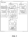
- FIG. 1 is a block diagram illustrating an example of configurations of main components in the robot system 1.
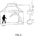
- FIG. 2 is a schematic view illustrating an outline of the robot system 1.
- the robot system 1 can monitor a position of an operator with a three-dimensional monitoring sensor 11.
- the robot system 1 can perform work by causing an arm 30 supported by a platform to operate.
- the aforementioned processing is controlled by a control unit 40 that the robot system 1 has.
- the robot system 1 can receive hazardous part information related to positions and a direction of a hazardous part by an information input unit 41 when the arm 30 and the work target (hereinafter referred to as a workpiece) have a hazardous part. Further, the robot system 1 can cause the arm 30 to operate such that the hazardous direction of the hazardous part is different from a moving direction of a grip unit of the arm 30 on the basis of the received hazardous part information.
- the workpiece may have a shape with which the arm 30 can grip the workpiece by using the grip unit.
- the hazardous part is a part that may injure the operator when the hazardous part collides with the operator, and for example, is a protrusion with a sharp tip end.
- the hazardous direction is a direction in which the operator may be injured when the hazardous part collides with the operator, and if the hazardous part is a protrusion, for example, the hazardous direction is a direction in which the protrusion is pressed against the operator. If the protrusion is pressed against the operator at this time, the operator is stabbed and injured.
- the robot system 1 includes a three-dimensional monitoring sensor 11, an emergency stop switch 12, an input device 13, a storage unit 20, the arm 30, and the control unit 40.
- the storage unit 20 includes an operation program 21 and hazardous part information 22, and the arm 30 includes a grip unit 31.
- the control unit 40 includes an information input unit 41, an arm operation control unit 42, and a position detection unit 43. Note that, although an operation direction leading unit 32 is illustrated in FIG. 1 in addition to the aforementioned configurations, the operation direction leading unit 32 is not essential in the embodiment. Details of these members will be described later.
- the robot system 1 can cause the respective components to operate in accordance with the operation program 21. More specifically, the robot system 1 can cause the arm 30 to operate in accordance with the operation program 21.
- control unit 40 may be connected for communication with higher-level devices such as a controller, for example, and change content of operations in the operation program 21 in response to instructions from the controller, though this is not illustrated in the drawing.
- higher-level devices such as a controller, for example, and change content of operations in the operation program 21 in response to instructions from the controller, though this is not illustrated in the drawing.
- an actual operation status of the arm 30, imaging data obtained by the three-dimensional monitoring sensor 11, and the like may be transmitted to the controller.
- the three-dimensional monitoring sensor 11 is a sensor capable of detecting the position of the operator near the robot system 1.
- the three-dimensional monitoring sensor 11 may be a laser scanner that scans laser light in a predetermined range, for example, and detects presence of the operator depending on whether or not there is reflected light.
- the three-dimensional monitoring sensor 11 can transmit the detection result to the position detection unit 43.
- the emergency stop switch 12 is a switch capable of stopping operations of the arm 30 in an emergency.
- the emergency stop switch 12 is arranged outside an operation range of the arm 30, for example, and may be arranged at a position at which another operator who has determined there is a possibility that the arm 30 may collide with the operator can easily press the emergency stop switch 12. If the emergency stop switch 12 is pressed, a notification is provided to the position detection unit 43. Furthermore, the emergency stop switch 12 may be connected to the arm operation control unit 42, and if the emergency stop switch 12 is pressed at this time, a notification is provided to the arm operation control unit 42.
- the input device 13 is a device for a user to provide various inputs to the robot system 1.
- the user can input hazardous part information related to the position of the hazardous part and the hazardous direction of at least one of the grip unit 31 and the workpiece gripped with the grip unit 31 to the robot system 1 via the input device 13.
- the input device 13 may be a general personal computer, for example.
- the storage unit 20 can retain various kinds of data to be handled by the robot system 1.
- the storage unit 20 includes at least the operation program 21 and the hazardous part information 22.
- the operation program 21 is a program in which processing necessary for operations of the robot system 1 is described.
- the operation program 21 is read by the control unit 40, and the control unit 40 can cause the respective components to operate in accordance with the content of the description in the operation program 21.
- the hazardous part information 22 is information related to the position of the hazardous part and the hazardous direction of at least any one of the grip unit 31 and the workpiece gripped with the grip unit 31, which has been input by the user using the input device 13 and has been received by the information input unit 41.
- the hazardous part information 22 may include a shape and a position of a workpiece, and a relative position of hazardous parts that the workpiece has, for example.
- the arm 30 is a part that the robot system 1 uses for operations.
- the arm 30 may be a flexible arm having a plurality of joints, for example.
- the arm 30 can operate in accordance with control performed by the arm operation control unit 42.
- the grip unit 31 is provided at a tip end of the arm 30 and can operate in accordance with the control performed by the control unit 40.
- the grip unit 31 has a robot hand-shape, for example, and can grip the workpiece.
- the grip unit 31 may be configured to have a hazardous part or may be configured not to have a hazardous part.
- the control unit 40 comprehensively controls the respective components of the robot system 1.
- the control unit 40 can receive the hazardous part information input from the input device 13 by the information input unit 41 and record the hazardous part information in the storage unit 20.
- the control unit 40 can provide instructions to the arm operation control unit 42 to cause the arm 30 to operate in the manner of the hazardous direction of the hazardous part is different from the moving direction of the grip unit 31 on the basis of the hazardous part information 22. Further, the control unit 40 can provide, on the basis of the hazardous part information, an instruction for switching the hazardous direction of the hazardous part under a state in which the grip unit 31 is not gripping the workpiece and a state in which the grip unit 31 is gripping the workpiece to the arm operation control unit 42.
- the control unit 40 can determine whether the detected position of the operator is in the moving direction of the grip unit 31. If the position detection unit 43 receives the fact that the emergency stop switch 12 has been pressed, the control unit 40 can stop operations of the arm 30 via the arm operation control unit 42.
- the information input unit 41 can receive the hazardous part information related to the position of the hazardous part and the hazardous direction of at least any one of the grip unit 31 and the workpiece gripped with the grip unit 31, which has been input by the user via the input device 13, and store the hazardous part information in the hazardous part information 22. Furthermore, the information input unit 41 may receive the hazardous part information from a communication network, which is not illustrated in the drawing, for example, and store the hazardous part information in the storage unit 20.
- the arm operation control unit 42 can cause the arm 30 to operate in accordance with instructions from the control unit 40.
- the arm operation control unit 42 can cause the arm 30 to operate in a manner of the hazardous direction of the hazardous part is different from the moving direction of the grip unit 31 on the basis of the hazardous part information read from the hazardous part information 22.
- the arm operation control unit 42 can receive a result of detecting the operator by the position detection unit 43 and cause the arm 30 to operate in accordance with the detection result.
- the arm operation control unit 42 can cause the arm 30 to operate with operations that are different from those when the arm operation control unit 42 does not detect the operator, for example.
- the position detection unit 43 can detect the position of the operator near the robot system 1. Specifically, the position detection unit 43 can detect the position of the operator near the robot system 1 by using the three-dimensional monitoring sensor 11 and transmit the detection result to the arm operation control unit 42.
- FIG. 3A and 3B are schematic views illustrating the relation between the moving direction of the grip unit 31 and the orientation of the hazardous part in the robot system 1.
- FIG. 3A illustrates a case in which the workpiece gripped with the grip unit 31 has a hazardous part and the hazardous part is oriented in the same direction as the moving direction of the grip unit 31.
- FIG. 3B illustrates a case in which the workpiece gripped with the grip unit 31 has a hazardous part and the hazardous part is oriented in a different direction from the moving direction of the grip unit 31.
- the arm 30 retains the workpiece by using the grip unit 31.
- the workpiece has a protrusion as a hazardous part, and the tip end of the protrusion is directed in the same direction as the moving direction of the grip unit 31. That is, if the grip unit 31 is caused to operate while keeping the state as illustrated in the drawing, the arm 30 operates in a manner of the protrusion of the workpiece would pierce in the moving direction of the grip unit 31. At this time, there is a concern that the operator may be stabbed (pierced) and injured by the protrusion of the workpiece if the operator is in the moving direction of the grip unit 31, for example.
- FIG. 3B illustrates the arm 30 in a case in which the hazardous part of the workpiece is oriented in the orientation opposite to the moving direction of the grip unit 31. At this time, the operator is not stabbed and injured by the protrusion of the workpiece even in a case in which the operator is in the moving direction of the grip 3, for example.
- control unit 40 can determine, from the hazardous part information received from the information input unit 41 and the moving direction of the grip unit 31, which one of combinations in FIG. 3A and FIG. 3B is the combination between the moving direction of the grip unit 31 and the orientation of the hazardous part of the workpiece.
- the grip unit 31 may be configured to have a hazardous part.
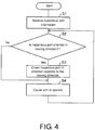
- FIG. 4 is a flowchart illustrating an example of a flow of processing that is executed by the robot system 1.
- the information input unit 41 receives hazardous part information input from the user via the input device 13 and stores the hazardous part information in the hazardous part information 22 in the storage unit 20 (S1).
- the control unit 40 determines whether the hazardous part is currently oriented in the moving direction of the grip unit 31 from the information stored in the hazardous part information 22 in S1 (S2). In a case in which it is determined that the hazardous part is oriented in the moving direction of the grip unit 31 (YES in S2), the arm operation control unit 42 orients the hazardous part in the direction opposite to the moving direction of the grip unit 31 (S3) and then causes the grip unit 31 to operate in the moving direction (S4).
- the processing proceeds to S4, and the arm operation control unit 42 causes the arm 30 to operate (in the moving direction) without changing the orientation of the hazardous part. If the arm 30 is caused to operate in S4, then the robot system 1 waits for the next reception of an instruction for causing the arm 30 to operate. If the instruction for causing the arm 30 to operate is received, the processing in S2 to S4 is repeated.
- the robot system 1 can cause the arm 30 to operate while the hazardous direction of the hazardous part is oriented in a direction different from the moving direction of the grip unit 31 when at least one of the grip unit 31 and the work target has the hazardous part. In this manner, it is possible to suppress injury to an operator due to collision of the hazardous part with the operator when the operator is in the operation direction of the arm 30, for example. Therefore, the effect that it is possible to provide a highly safe robot system is achieved.
- FIG. 5A and 5B are schematic views illustrating a relation between a moving direction of the grip unit 31 and an orientation of a hazardous part in a case in which the hazardous part is set at the grip unit 31, in the robot system 1.
- FIG. 5A and 5B are schematic views illustrating a relation between a moving direction of the grip unit 31 and an orientation of a hazardous part in a case in which the hazardous part is set at the grip unit 31, in the robot system 1.
- FIG. 5A illustrates a state before the arm 30 is caused to operate
- FIG. 5B illustrates a state when the arm 30 is caused to operate
- FIG. 6A and 6B are schematic views illustrating a relation between a moving direction of the grip unit 31 and an orientation of a hazardous part in a case in which the hazardous part is set at the workpiece, in the robot system 1.
- FIG. 6A illustrates a state before the arm 30 is caused to operate
- FIG. 6B illustrates a state in which the arm 30 grips the workpiece by using the grip unit 31 and is operating.
- FIG. 5A illustrates a state in which the arm 30 is not operating and the grip unit 31 that has the hazardous part has the hazardous part oriented to the lower side in the vertical direction.
- the tip end portion surrounded by the circle mark in the grip unit 31 is a tip end of a protrusion and is a hazardous part for which there is concern that the operator may be stabbed and injured at the time of collision. Since the arm 30 is not operating in the state in FIG. 5A , the possibility that the user may be stabbed and injured by the protrusion is low.
- FIG. 5B illustrates a state in which the grip unit 31 is operating in the moving direction.
- the hazardous part that the grip unit 31 has is controlled by the arm operation control unit 42 to be oriented in the direction opposite to the moving direction of the grip unit 31. That is, the hazardous part surrounded by the circle mark in the grip unit 31 is oriented in the direction opposite to the moving direction of the grip unit 31, and the entire arm 30 operates in the direction opposite to the direction represented by the arrow in the drawing as the "Moving direction of grip unit". Since the protrusion is not pressed in the "Hazardous direction", it is possible to provide a highly safe robot system with a suppressed possibility of the operator being injured by the hazardous part that the grip unit 31 has.
- FIG. 6A illustrates a state in which a bar-shaped workpiece that has a protrusion at one end is present in addition to the state in FIG. 5A .
- the part surrounded by the circle including the protrusion is a hazardous part of the workpiece for which there is concern that the operator may be stabbed and injured at the time of collision.
- the direction represented by the arrow in the drawing as the "Hazardous direction" is a direction in which the operator may be stabbed and injured by the protrusion of the workpiece, and if the protrusion is pressed in the "Hazardous direction," the operator may be stabbed and injured. Since the workpiece is not moving in the state in FIG. 6A , the possibility of the user being stabbed and injured by the protrusion is low.
- FIG. 6B illustrates a state when the grip unit 31 grips the workpiece and operates in the moving direction of the grip unit 31. Since the hazardous part of the workpiece is set in a region including the protrusion in the example illustrated in the drawing, the arm operation control unit 42 grips the workpiece in a manner of that the "Hazardous direction" corresponding to the orientation of the hazardous part is oriented in the direction opposite to the moving direction of the grip unit 31. Since the entire arm 30 operates in the direction opposite to the "Moving direction of grip unit" in this manner, the protrusion of the workpiece is not pressed in the "Hazardous direction.” Therefore, it is possible to provide a highly safe robot system that suppresses stabbing and injury of the operator by the protrusion that the workpiece has.
- the arm operation control unit 42 can switch the hazardous parts in accordance with information related to a position of a hazardous part and a hazardous direction of at least one of the grip unit 31 and the workpiece, which is stored in the hazardous part information 22. That is, when the grip unit 31 has the hazardous part and does not hold a workpiece or holds a workpiece with no hazardous part, the arm operation control unit 42 can cause the arm to operate such that the hazardous direction of the hazardous part of the grip unit 31 is different from the moving direction of the grip unit 31. Meanwhile, when the workpiece has a hazardous part and the grip unit 31 grips the workpiece, the arm operation control unit 42 can cause the arm to operate such that the hazardous direction of the hazardous part of the workpiece is different from the moving direction of the grip unit 31.
- the arm 30 may be configured to further include the operation direction leading unit 32.
- the operation direction leading unit 32 is provided (disposed) at a predetermined location of the arm 30 and can move in the moving direction prior to the grip unit 31 and the workpiece gripped with the grip unit 31 when the entire arm 30 operates in the moving direction of the grip unit 31.
- the operation direction leading unit 32 may have any configuration, the operation direction leading unit 32 may have a shape that is partially rounded with a low possibility that the operation direction leading unit 32 injures the operator even if the operation direction leading unit 32 collides against the operator, for example.
- the operation direction leading unit 32 may be provided at any location of the arm 30, the operation direction leading unit 32 may be provided at a position at which the operation direction leading unit 32 is automatically oriented in the operation direction if the hazardous part is oriented in a direction different from the moving direction of the grip unit 31 when at least any of the grip unit 31 and the workpiece has the hazardous part.
- the operation direction leading unit 32 may have a rounded shape that is provided at a boundary between the arm 30 and the grip unit 31 and is represented by a circular shape or a curved line in each of FIGS. 3A-3B , 5A-5B , and 6A-6B , for example.
- the arm operation control unit 42 can cause the arm 30 to operate in the manner that the hazardous part is oriented in a direction different from the moving direction of the grip unit 31 and the rounded shape is oriented in the operation direction on the basis of information acquired from the hazardous part information 22 when the hazardous part is set in at least any of the grip unit 31 and the workpiece.
- FIGS. 1 and 7 A second embodiment of the invention will be described below with reference to FIGS. 1 and 7 . Furthermore, the same reference numerals will be given to members that have the same functions as those of the members described in the aforementioned embodiment for convenience of description, and description thereof will be omitted.
- a configuration of a robot system 1 according to the embodiment will be described with reference to FIG. 1 .
- the arm operation control unit 42 is different in that a moving speed of the grip unit 31 is caused to change in accordance with a position of an operation detected by the position detection unit 43. More specifically, the arm operation control unit 42 can cause the arm 30 to operate at a low speed when the position of the operator detected by the position detection unit 43 is within a moving direction region set in accordance with the moving direction of the grip unit 31. Further, after the arm 30 is caused to operate at the low speed, the arm operation control unit 42 can cause the arm 30 to operate at an ordinary speed that is higher than the low-speed operation in the operation direction when the position detection unit 43 does not detect the operator in the moving direction region.
- the moving direction region is a predetermined region set in the moving direction of the grip unit 31.
- the moving direction region is a region set with respect to the direction in which the arm 30 operates, for example, and is a predetermined region that is regarded as having a possibility that the operator may collide against the arm 30 if the operator is present in the moving direction region.
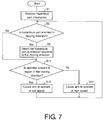
- FIG. 7 is a flowchart illustrating an example of a flow of processing that is executed by the robot system 1.
- Processing in S1 to S3 is the same as that in the aforementioned first embodiment.
- the arm operation control unit 42 determines whether or not an operator is present in the moving direction region set in accordance with the moving direction of the grip unit 31 from the detection result obtained by the position detection unit 43 (S11). In a case in which it is determined that the operator is present (YES in S11), the arm operation control unit 42 causes the arm 30 to operate at a low speed (S12). If the arm 30 is caused to operate at the low speed in the operation direction in S12, the robot system 1 waits for the next reception of an instruction for causing the arm 30 to operate. If the instruction for causing the arm 30 to operate is received, the processing in and after S2 is repeated.
- the arm operation control unit 42 causes the arm 30 to operate at a high speed (S13). If the arm 30 is caused to operate at the high speed in the operation direction in S13, the robot system 1 waits for the next reception of the instruction for causing the arm 30 to operate. If the instruction for causing the arm 30 to operate is received, the processing in and after S2 is repeated.
- the robot system 1 can orient the hazardous part in a direction different from the moving direction of the grip unit 31, and further, when the operator is present in the moving direction region set in accordance with the moving direction of the grip unit 31, the robot system 1 can cause the entire arm 30 to operate at the low speed. Further, if the robot system 1 detects that the operator has stepped away from the moving direction region, the arm 30 can be caused to operate at the ordinary speed. In this manner, it is possible to suppress collision of the arm 30 against the operator and to suppress impact at the time of the collision. Therefore, the effect that it is possible to provide a further highly safe robot system is achieved.
- the aforementioned configuration is a configuration in which the arm operation control unit 42 causes the arm 30 to operate at the low speed when the position detection unit 43 detects the operator in the moving direction region.
- a configuration in which the arm operation control unit 42 stops the operations of the arm 30 when the operator is detected in the moving direction region may be employed as long as it is possible to suppress collision of the arm 30 against the operator.
- the arm operation control unit 42 may be configured to restart the operations of the arm 30 if the position detection unit 43 does not detect the operator in the moving direction region.
- the orientation in which the grip unit 31 grips the workpiece is not particularly limited in the configuration in the aforementioned respective embodiments.
- the arm operation control unit 42 may cause the arm 30 to operate while both a hazardous part of the grip unit and a hazardous part of the workpiece are oriented in a direction different from the moving direction of the grip unit 31 when both the grip unit 31 and the workpiece have the hazardous parts. That is, the arm operation control unit 42 may set both hazardous directions to directions different from the moving direction of the grip unit 31 when the hazardous direction of the hazardous part of the grip unit 31 and the hazardous direction of the hazardous part of the workpiece are different directions.
- the hazardous part information is set for one type of workpiece and the hazardous direction of the hazardous part is oriented in a direction different from the moving direction of the grip unit 31 in the configuration in the aforementioned respective embodiments
- a configuration in which the hazardous part information is set for a plurality of types of workpieces may be employed.
- the robot system 1 may be configured to specify the types of the workpieces first and orient the hazardous directions of the hazardous parts in directions different from the moving direction of the grip unit 31 on the basis of thee hazardous part information in accordance with the specified types.
- the arm operation control unit 42 may switch the hazardous directions of the hazardous parts in accordance with an angle at which the grip unit 31 is gripping the workpiece in addition to the hazardous part information.
- the angle at which the grip unit 31 is gripping the workpiece may be set in advance in accordance with a mounting position and a mounting state of the workpiece at the time of a start of the operation of gripping the workpiece with the grip unit 31.
- the angle may be recognized by a workpiece gripping angle detection unit such as an image sensor.
- a robot system (1) includes: an arm operation control unit (42) that controls operations of an arm (30); and a storage unit (20) that records hazardous part information (22) related to a position of a hazardous part and a hazardous direction of at least any one of a grip unit (31) of the arm and a work target gripped with the grip unit, in which the arm operation control unit causes the arm to operate such that the hazardous direction of the hazardous part is different from a moving direction of the grip unit on the basis of the hazardous part information.
- the robot system can cause the arm to operate while the hazardous direction of the hazardous part is oriented in a direction different from the moving direction of the grip unit when at least any of the grip unit and the work target has the hazardous part. In this manner, it is possible to suppress stabbing and injuring the operator due to collision of the hazardous part against the operator when the operator is present in the moving direction of the grip unit, for example. Therefore, the effect that it is possible to provide a highly safe robot system is achieved.
- the robot system (1) may further include: an information input unit (41) that receives the hazardous part information (22), in the first aspect.
- the robot system it is possible to cause the robot system to perform the aforementioned hazard avoidance operation by the user inputting the hazardous part information to the information input unit, for example. That is, it is possible to update the hazardous part information in accordance with a change or the like in the work target, for example.
- the arm operation control unit (42) may switch the hazardous direction of the hazardous part between a state in which the grip unit (31) is gripping the work target and a state in which the grip unit (31) is not gripping the work target, in the first or second aspect.
- the robot system can cause the arm to operate while the hazardous direction of the hazardous part is oriented in a direction different from the moving direction of the grip unit on the basis of the recorded hazardous part information of any of the grip unit and the work target in accordance with whether or not the grip unit is gripping the work target.
- the arm it is possible to cause the arm to operate while the hazardous direction of the hazardous part that the grip unit has is oriented in a direction different from the moving direction of the grip unit when the grip unit and the work target have hazardous parts and the grip unit does not grip the work target, for example.
- the grip unit grips the work target, it is possible to cause the arm to operate while the hazardous direction of the hazardous part is oriented in a direction different from the moving direction of the grip unit, for the hazardous part that the work target has.
- the arm operation control unit (42) may switch the hazardous direction of the hazardous part in accordance with a type of the work target that the grip unit (31) is gripping, in any of the first to third aspects.
- the robot system can switch the hazardous direction of the hazardous part in accordance with the type of the work target. Accordingly, it is possible to cause the robot system to perform the aforementioned hazard avoidance operation in accordance with the types of the respective work targets in a case in which the robot system operates while switching and gripping a plurality of types of work targets in accordance with a situation, for example.
- an operation direction leading unit (32) may be provided at a predetermined location of the arm (30), and the arm operation control unit (42) may cause the arm to operate such that the operation direction leading unit leads and the grip unit follows the operation direction leading unit in the moving direction of the grip unit (31), in any of the first to fourth aspects.
- the robot system can cause the arm to operate such that the operation direction leading unit leads the grip unit in the moving direction of the grip unit.
- the arm can cause the arm to operate such that the operation direction leading unit leads the grip unit in the moving direction of the grip unit.
- it is possible to suppress traumatic injury of the operator even of the operation direction leading unit collides against the operator, by providing a rounded shape to the operation direction leading unit or forming the operation direction leading unit by a flexible material, for example. Therefore, the effect that it is possible to provide a further highly safe robot system is achieved.
- the robot system (1) may further include a position detection unit (43) that detects a position of an operator near the robot system, the arm operation control unit (42) may stop operations of the arm (30) or causes the arm (30) to operate at a low speed when the position of the operator detected by the position detection unit is within a moving direction region set in accordance with the moving direction of the grip unit (31), in any of the first to fifth aspect.
- a position detection unit (43) that detects a position of an operator near the robot system
- the arm operation control unit (42) may stop operations of the arm (30) or causes the arm (30) to operate at a low speed when the position of the operator detected by the position detection unit is within a moving direction region set in accordance with the moving direction of the grip unit (31), in any of the first to fifth aspect.
- the robot system can stop the operations of the arm or cause the arm to operate at a low speed when the operator is present in the moving direction region. In this manner, it is possible to suppress collision of the arm against the operator and to suppress impact at the time of the collision. Therefore, the effect that it is possible to provide a further highly safe robot system is achieved.
- the arm operation control unit (42) may restart the operations of the arm and cause the arm to operate at an ordinary speed in a case in which the position detection unit (43) does not detect the operator in the moving direction region after the operations of the arm (30) are stopped or the arm (30) is caused to operate at the low speed, in the sixth aspect.
- the robot system can restart the operations of the arm or cause the arm to operate at the ordinary speed if the fact that the operator has stepped away from the moving direction region is detected. In this manner, the effect that it is possible to provide a robot system with enhanced safety and enhanced operation efficiency by further continuing the operations is achieved.
- Control blocks (the information input unit 41 and the arm operation control unit 42, in particular) in the robot system 1 may be implemented by a logic circuit (hardware) formed on an integrated circuit (IC chip) or the like or may be realized by software by using a central processing unit (CPU).
- a logic circuit hardware
- IC chip integrated circuit
- CPU central processing unit
- the robot system 1 includes a CPU that execute orders of a program that is software for implementing the respective functions, a read only memory (ROM) or a storage device (these will be referred to as a "recording medium") in which the aforementioned program and various kinds of data are recorded in a computer (or a CPU) readable manner, a random access memory (RAM) that develops the aforementioned program, and the like. Then, the object of one or some embodiments of the invention is achieved by a computer (or the CPU) reading the aforementioned program from the aforementioned recording medium and executing the program.
- ROM read only memory
- RAM random access memory
- a "non-transitory tangible medium” such as a tape, a disc, a card, a semiconductor memory, or a programmable logic circuit, for example can be used.
- the aforementioned program may be supplied to the aforementioned computer via an arbitrary transmission medium (a communication network, a broadcasting wave, or the like) capable of transmitting the program.
- an aspect of the invention can also be implemented in a form of data signals, in which the aforementioned program is realized by electronic transmission, which are incorporated in carrier waves.
Landscapes
- Engineering & Computer Science (AREA)
- Robotics (AREA)
- Mechanical Engineering (AREA)
- Automation & Control Theory (AREA)
- Manipulator (AREA)
Abstract
Description
- The disclosure relates to a robot system that operates by a program.
- A robot system in which an arm that can operate to perform work is provided is known as a technology in the related art. For such a robot system, a technique for suppressing injury to an operator due to collision of the arm with the operator when the operator performs work near the robot system during operations of the arm is also known. For example, Patent Document 1 discloses an avoidance track generation apparatus that generates an avoidance track in order for an operator not to collide with a protrusion when it is detected that the operator is approaching an industrial robot that has a protrusion. Patent Document 2 discloses an end effector that accommodates a claw member, which may be unfavorably brought into contact with an operator, in a cover portion.
- [Patent Document 1] Japanese Laid-open No. No.
2016-196069 - [Patent Document 2] Japanese Laid-open No.
2009-78324 - However, the techniques in the related art as described above do not reliably prevent collision of the operator with the protrusion. For example, in Patent Document 1, although the collision of the operator with the protrusion is avoided by using the avoidance track, there is a problem that a calculation load is needed to generate the avoidance track and an avoidable range is limited. In addition, in Patent Document 2, although the claw member that has a protrusion is configured to be accommodated in the cover portion, there is a problem that the size of a work target (workpiece) that can be gripped with the claw member is restricted by the size of the cover portion.
- An object of an aspect of the invention is to provide a highly safe robot system capable of reliably preventing collision of an operator with a protrusion.
- In order to solve the aforementioned problem, a robot system according to an aspect of the invention includes: an arm operation control unit that controls operations of an arm; and a storage unit that records hazardous (dangerous) part information related to a position of a hazardous part and a hazardous direction of at least any one of a grip unit of the arm and a work target gripped with the grip unit, and the arm operation control unit causes the arm to operate such that the hazardous direction of the hazardous part is different from a moving direction of the grip unit on the basis of the hazardous part information.
- The robot system according to an aspect of the invention may further include: an information input unit that receives the hazardous part information.
- In the robot system according to an aspect of the invention, the arm operation control unit may switch the hazardous direction of the hazardous part between a state in which the grip unit is gripping the work target and a state in which the grip unit is not gripping the work target.
- In the robot system according to an aspect of the invention, an operation direction leading unit may be provided at a predetermined location of the arm, and the arm operation control unit may cause the arm to operate such that the operation direction leading unit leads and the grip unit follows the operation direction leading unit in the moving direction of the grip unit.
- The robot system according to an aspect of the invention may further include: a position detection unit that detects a position of an operator who is near the robot system, and the arm operation control unit may stop operations of the arm or cause the arm to operate at a low speed when the position of the operator detected by the position detection unit is within a moving direction region set in accordance with the moving direction of the grip unit.
- In the robot system according to an aspect of the invention, the arm operation control unit may restart the operations of the arm or cause the arm to operate at an ordinary speed in a case in which the position detection unit does not detect the operator in the moving direction region after the operations of the arm are stopped or the arm is caused to operate at the low speed.
- According to an aspect of the invention, an effect that it is possible to provide a highly safe robot system is achieved.
-
-
FIG. 1 is a block diagram illustrating an example of configurations of main components in a robot system according to a first embodiment of the invention. -
FIG. 2 is a schematic view illustrating an outline of the robot system according to the first embodiment of the invention. -
FIG. 3A and 3B are schematic views illustrating a relation between a moving direction of a grip unit and an orientation of a hazardous part in the robot system according to the first embodiment of the invention. -
FIG. 4 is a flowchart illustrating an example of processing that the robot system according to the first embodiment of the invention executes. -
FIG. 5A and 5B are schematic views illustrating a relation between a moving direction of the grip unit and an orientation of a hazardous part in a case in which the grip unit has the hazardous part in the robot system according to the first embodiment of the invention, whereinFIG. 5A illustrates a state before an arm is caused to operate, andFIG. 5B illustrates a state when the arm is caused to operate. -
FIG. 6A and 6B are schematic views illustrating a relation between a moving direction of the grip unit and an orientation of a hazardous part in a case in which a workpiece has the hazardous part in the robot system according to the first embodiment of the invention, whereinFIG. 6A illustrates a state before the arm is caused to operate, andFIG. 6B illustrates a state when the arm gripping the workpiece with the grip unit is caused to operate. -
FIG. 7 is a flowchart illustrating an example of processing that a robot system according to a second embodiment of the invention executes. - A first embodiment of the invention will be described below with reference to
FIGS. 1 to 6B . - An outline and a configuration of a robot system 1 according to an aspect of the invention will be described with reference to
FIGS. 1 and2 .FIG. 1 is a block diagram illustrating an example of configurations of main components in the robot system 1.FIG. 2 is a schematic view illustrating an outline of the robot system 1. - First, the outline of the robot system 1 will be described with reference to
FIG. 2 . According to the example illustrated in the drawing, the robot system 1 can monitor a position of an operator with a three-dimensional monitoring sensor 11. The robot system 1 can perform work by causing anarm 30 supported by a platform to operate. The aforementioned processing is controlled by acontrol unit 40 that the robot system 1 has. - In addition, the robot system 1 can receive hazardous part information related to positions and a direction of a hazardous part by an
information input unit 41 when thearm 30 and the work target (hereinafter referred to as a workpiece) have a hazardous part. Further, the robot system 1 can cause thearm 30 to operate such that the hazardous direction of the hazardous part is different from a moving direction of a grip unit of thearm 30 on the basis of the received hazardous part information. Here, the workpiece may have a shape with which thearm 30 can grip the workpiece by using the grip unit. Further, the hazardous part is a part that may injure the operator when the hazardous part collides with the operator, and for example, is a protrusion with a sharp tip end. The hazardous direction is a direction in which the operator may be injured when the hazardous part collides with the operator, and if the hazardous part is a protrusion, for example, the hazardous direction is a direction in which the protrusion is pressed against the operator. If the protrusion is pressed against the operator at this time, the operator is stabbed and injured. - Next, a configuration of the robot system 1 will be described with reference to
FIG. 1 . According to the example illustrated in the drawing, the robot system 1 includes a three-dimensional monitoring sensor 11, anemergency stop switch 12, aninput device 13, astorage unit 20, thearm 30, and thecontrol unit 40. In addition, thestorage unit 20 includes anoperation program 21 andhazardous part information 22, and thearm 30 includes agrip unit 31. Further, thecontrol unit 40 includes aninformation input unit 41, an armoperation control unit 42, and aposition detection unit 43. Note that, although an operationdirection leading unit 32 is illustrated inFIG. 1 in addition to the aforementioned configurations, the operationdirection leading unit 32 is not essential in the embodiment. Details of these members will be described later. - The robot system 1 can cause the respective components to operate in accordance with the
operation program 21. More specifically, the robot system 1 can cause thearm 30 to operate in accordance with theoperation program 21. - Furthermore, the
control unit 40 may be connected for communication with higher-level devices such as a controller, for example, and change content of operations in theoperation program 21 in response to instructions from the controller, though this is not illustrated in the drawing. In addition, an actual operation status of thearm 30, imaging data obtained by the three-dimensional monitoring sensor 11, and the like may be transmitted to the controller. - The three-
dimensional monitoring sensor 11 is a sensor capable of detecting the position of the operator near the robot system 1. The three-dimensional monitoring sensor 11 may be a laser scanner that scans laser light in a predetermined range, for example, and detects presence of the operator depending on whether or not there is reflected light. The three-dimensional monitoring sensor 11 can transmit the detection result to theposition detection unit 43. - The
emergency stop switch 12 is a switch capable of stopping operations of thearm 30 in an emergency. Theemergency stop switch 12 is arranged outside an operation range of thearm 30, for example, and may be arranged at a position at which another operator who has determined there is a possibility that thearm 30 may collide with the operator can easily press theemergency stop switch 12. If theemergency stop switch 12 is pressed, a notification is provided to theposition detection unit 43. Furthermore, theemergency stop switch 12 may be connected to the armoperation control unit 42, and if theemergency stop switch 12 is pressed at this time, a notification is provided to the armoperation control unit 42. - The
input device 13 is a device for a user to provide various inputs to the robot system 1. The user can input hazardous part information related to the position of the hazardous part and the hazardous direction of at least one of thegrip unit 31 and the workpiece gripped with thegrip unit 31 to the robot system 1 via theinput device 13. Theinput device 13 may be a general personal computer, for example. - The
storage unit 20 can retain various kinds of data to be handled by the robot system 1. In the example illustrated in the drawing, thestorage unit 20 includes at least theoperation program 21 and thehazardous part information 22. - The
operation program 21 is a program in which processing necessary for operations of the robot system 1 is described. Theoperation program 21 is read by thecontrol unit 40, and thecontrol unit 40 can cause the respective components to operate in accordance with the content of the description in theoperation program 21. - The
hazardous part information 22 is information related to the position of the hazardous part and the hazardous direction of at least any one of thegrip unit 31 and the workpiece gripped with thegrip unit 31, which has been input by the user using theinput device 13 and has been received by theinformation input unit 41. Thehazardous part information 22 may include a shape and a position of a workpiece, and a relative position of hazardous parts that the workpiece has, for example. - The
arm 30 is a part that the robot system 1 uses for operations. Thearm 30 may be a flexible arm having a plurality of joints, for example. Thearm 30 can operate in accordance with control performed by the armoperation control unit 42. - The
grip unit 31 is provided at a tip end of thearm 30 and can operate in accordance with the control performed by thecontrol unit 40. Thegrip unit 31 has a robot hand-shape, for example, and can grip the workpiece. Furthermore, thegrip unit 31 may be configured to have a hazardous part or may be configured not to have a hazardous part. - The
control unit 40 comprehensively controls the respective components of the robot system 1. Thecontrol unit 40 can receive the hazardous part information input from theinput device 13 by theinformation input unit 41 and record the hazardous part information in thestorage unit 20. Thecontrol unit 40 can provide instructions to the armoperation control unit 42 to cause thearm 30 to operate in the manner of the hazardous direction of the hazardous part is different from the moving direction of thegrip unit 31 on the basis of thehazardous part information 22. Further, thecontrol unit 40 can provide, on the basis of the hazardous part information, an instruction for switching the hazardous direction of the hazardous part under a state in which thegrip unit 31 is not gripping the workpiece and a state in which thegrip unit 31 is gripping the workpiece to the armoperation control unit 42. - In addition, if the
position detection unit 43 receives the detection result obtained by the three-dimensional monitoring sensor 11, then thecontrol unit 40 can determine whether the detected position of the operator is in the moving direction of thegrip unit 31. If theposition detection unit 43 receives the fact that theemergency stop switch 12 has been pressed, thecontrol unit 40 can stop operations of thearm 30 via the armoperation control unit 42. - The
information input unit 41 can receive the hazardous part information related to the position of the hazardous part and the hazardous direction of at least any one of thegrip unit 31 and the workpiece gripped with thegrip unit 31, which has been input by the user via theinput device 13, and store the hazardous part information in thehazardous part information 22. Furthermore, theinformation input unit 41 may receive the hazardous part information from a communication network, which is not illustrated in the drawing, for example, and store the hazardous part information in thestorage unit 20. - The arm
operation control unit 42 can cause thearm 30 to operate in accordance with instructions from thecontrol unit 40. The armoperation control unit 42 can cause thearm 30 to operate in a manner of the hazardous direction of the hazardous part is different from the moving direction of thegrip unit 31 on the basis of the hazardous part information read from thehazardous part information 22. In addition, the armoperation control unit 42 can receive a result of detecting the operator by theposition detection unit 43 and cause thearm 30 to operate in accordance with the detection result. When theposition detection unit 43 detects the operator, the armoperation control unit 42 can cause thearm 30 to operate with operations that are different from those when the armoperation control unit 42 does not detect the operator, for example. - The
position detection unit 43 can detect the position of the operator near the robot system 1. Specifically, theposition detection unit 43 can detect the position of the operator near the robot system 1 by using the three-dimensional monitoring sensor 11 and transmit the detection result to the armoperation control unit 42. - A relation between the moving direction of the
grip unit 31 and the orientation of the hazardous part in the robot system 1 according to the embodiment will be described with reference toFIG. 3A and 3B. FIG. 3A and 3B are schematic views illustrating the relation between the moving direction of thegrip unit 31 and the orientation of the hazardous part in the robot system 1.FIG. 3A illustrates a case in which the workpiece gripped with thegrip unit 31 has a hazardous part and the hazardous part is oriented in the same direction as the moving direction of thegrip unit 31.FIG. 3B illustrates a case in which the workpiece gripped with thegrip unit 31 has a hazardous part and the hazardous part is oriented in a different direction from the moving direction of thegrip unit 31. - In
FIG. 3A , thearm 30 retains the workpiece by using thegrip unit 31. In addition, the workpiece has a protrusion as a hazardous part, and the tip end of the protrusion is directed in the same direction as the moving direction of thegrip unit 31. That is, if thegrip unit 31 is caused to operate while keeping the state as illustrated in the drawing, thearm 30 operates in a manner of the protrusion of the workpiece would pierce in the moving direction of thegrip unit 31. At this time, there is a concern that the operator may be stabbed (pierced) and injured by the protrusion of the workpiece if the operator is in the moving direction of thegrip unit 31, for example. - Meanwhile,
FIG. 3B illustrates thearm 30 in a case in which the hazardous part of the workpiece is oriented in the orientation opposite to the moving direction of thegrip unit 31. At this time, the operator is not stabbed and injured by the protrusion of the workpiece even in a case in which the operator is in the moving direction of the grip 3, for example. - Therefore, the
control unit 40 can determine, from the hazardous part information received from theinformation input unit 41 and the moving direction of thegrip unit 31, which one of combinations inFIG. 3A and FIG. 3B is the combination between the moving direction of thegrip unit 31 and the orientation of the hazardous part of the workpiece. - Furthermore, while the configuration in which the
grip unit 31 does not have a protrusion and only the workpiece has the hazardous part has been described in the example illustrated in the drawing, thegrip unit 31 may be configured to have a hazardous part. - A flow of processing that is executed by the robot system 1 according to the embodiment will be described with reference to
FIG. 4. FIG. 4 is a flowchart illustrating an example of a flow of processing that is executed by the robot system 1. - First, the
information input unit 41 receives hazardous part information input from the user via theinput device 13 and stores the hazardous part information in thehazardous part information 22 in the storage unit 20 (S1). Next, thecontrol unit 40 determines whether the hazardous part is currently oriented in the moving direction of thegrip unit 31 from the information stored in thehazardous part information 22 in S1 (S2). In a case in which it is determined that the hazardous part is oriented in the moving direction of the grip unit 31 (YES in S2), the armoperation control unit 42 orients the hazardous part in the direction opposite to the moving direction of the grip unit 31 (S3) and then causes thegrip unit 31 to operate in the moving direction (S4). Meanwhile, in a case in which it is determined that the hazardous part is not oriented in the moving direction of thegrip unit 31 in S2 (NO in S2), the processing proceeds to S4, and the armoperation control unit 42 causes thearm 30 to operate (in the moving direction) without changing the orientation of the hazardous part. If thearm 30 is caused to operate in S4, then the robot system 1 waits for the next reception of an instruction for causing thearm 30 to operate. If the instruction for causing thearm 30 to operate is received, the processing in S2 to S4 is repeated. - By the aforementioned processing, the robot system 1 can cause the
arm 30 to operate while the hazardous direction of the hazardous part is oriented in a direction different from the moving direction of thegrip unit 31 when at least one of thegrip unit 31 and the work target has the hazardous part. In this manner, it is possible to suppress injury to an operator due to collision of the hazardous part with the operator when the operator is in the operation direction of thearm 30, for example. Therefore, the effect that it is possible to provide a highly safe robot system is achieved. - The relation between the moving direction of the
grip unit 31 and the orientation of the hazardous part when the workpiece has the hazardous part has been described with reference toFIG. 3A and 3B . However, the hazardous part can also be set at thegrip unit 31. When the user sets hazardous parts at both thegrip unit 31 and the workpiece by using theinput device 13, for example, it is necessary for the robot system 1 to appropriately switch the hazardous parts in accordance with a state of the robot system 1 itself. The switching of the hazardous parts will be described with reference toFIGS. 5A-5B and6A-6B .FIG. 5A and 5B are schematic views illustrating a relation between a moving direction of thegrip unit 31 and an orientation of a hazardous part in a case in which the hazardous part is set at thegrip unit 31, in the robot system 1.FIG. 5A illustrates a state before thearm 30 is caused to operate, andFIG. 5B illustrates a state when thearm 30 is caused to operate.FIG. 6A and 6B are schematic views illustrating a relation between a moving direction of thegrip unit 31 and an orientation of a hazardous part in a case in which the hazardous part is set at the workpiece, in the robot system 1.FIG. 6A illustrates a state before thearm 30 is caused to operate, andFIG. 6B illustrates a state in which thearm 30 grips the workpiece by using thegrip unit 31 and is operating. -
FIG. 5A illustrates a state in which thearm 30 is not operating and thegrip unit 31 that has the hazardous part has the hazardous part oriented to the lower side in the vertical direction. In the example illustrated in the drawing, the tip end portion surrounded by the circle mark in thegrip unit 31 is a tip end of a protrusion and is a hazardous part for which there is concern that the operator may be stabbed and injured at the time of collision. Since thearm 30 is not operating in the state inFIG. 5A , the possibility that the user may be stabbed and injured by the protrusion is low. -
FIG. 5B illustrates a state in which thegrip unit 31 is operating in the moving direction. In the example illustrated in the drawing, the hazardous part that thegrip unit 31 has is controlled by the armoperation control unit 42 to be oriented in the direction opposite to the moving direction of thegrip unit 31. That is, the hazardous part surrounded by the circle mark in thegrip unit 31 is oriented in the direction opposite to the moving direction of thegrip unit 31, and theentire arm 30 operates in the direction opposite to the direction represented by the arrow in the drawing as the "Moving direction of grip unit". Since the protrusion is not pressed in the "Hazardous direction", it is possible to provide a highly safe robot system with a suppressed possibility of the operator being injured by the hazardous part that thegrip unit 31 has. -
FIG. 6A illustrates a state in which a bar-shaped workpiece that has a protrusion at one end is present in addition to the state inFIG. 5A . In the example illustrated in the drawing, the part surrounded by the circle including the protrusion is a hazardous part of the workpiece for which there is concern that the operator may be stabbed and injured at the time of collision. Furthermore, the direction represented by the arrow in the drawing as the "Hazardous direction" is a direction in which the operator may be stabbed and injured by the protrusion of the workpiece, and if the protrusion is pressed in the "Hazardous direction," the operator may be stabbed and injured. Since the workpiece is not moving in the state inFIG. 6A , the possibility of the user being stabbed and injured by the protrusion is low. -
FIG. 6B illustrates a state when thegrip unit 31 grips the workpiece and operates in the moving direction of thegrip unit 31. Since the hazardous part of the workpiece is set in a region including the protrusion in the example illustrated in the drawing, the armoperation control unit 42 grips the workpiece in a manner of that the "Hazardous direction" corresponding to the orientation of the hazardous part is oriented in the direction opposite to the moving direction of thegrip unit 31. Since theentire arm 30 operates in the direction opposite to the "Moving direction of grip unit" in this manner, the protrusion of the workpiece is not pressed in the "Hazardous direction." Therefore, it is possible to provide a highly safe robot system that suppresses stabbing and injury of the operator by the protrusion that the workpiece has. - In
FIGS. 5A-5B and6A-6B , the armoperation control unit 42 can switch the hazardous parts in accordance with information related to a position of a hazardous part and a hazardous direction of at least one of thegrip unit 31 and the workpiece, which is stored in thehazardous part information 22. That is, when thegrip unit 31 has the hazardous part and does not hold a workpiece or holds a workpiece with no hazardous part, the armoperation control unit 42 can cause the arm to operate such that the hazardous direction of the hazardous part of thegrip unit 31 is different from the moving direction of thegrip unit 31. Meanwhile, when the workpiece has a hazardous part and thegrip unit 31 grips the workpiece, the armoperation control unit 42 can cause the arm to operate such that the hazardous direction of the hazardous part of the workpiece is different from the moving direction of thegrip unit 31. - The
arm 30 may be configured to further include the operationdirection leading unit 32. The operationdirection leading unit 32 is provided (disposed) at a predetermined location of thearm 30 and can move in the moving direction prior to thegrip unit 31 and the workpiece gripped with thegrip unit 31 when theentire arm 30 operates in the moving direction of thegrip unit 31. Although the operationdirection leading unit 32 may have any configuration, the operationdirection leading unit 32 may have a shape that is partially rounded with a low possibility that the operationdirection leading unit 32 injures the operator even if the operationdirection leading unit 32 collides against the operator, for example. Although the operationdirection leading unit 32 may be provided at any location of thearm 30, the operationdirection leading unit 32 may be provided at a position at which the operationdirection leading unit 32 is automatically oriented in the operation direction if the hazardous part is oriented in a direction different from the moving direction of thegrip unit 31 when at least any of thegrip unit 31 and the workpiece has the hazardous part. The operationdirection leading unit 32 may have a rounded shape that is provided at a boundary between thearm 30 and thegrip unit 31 and is represented by a circular shape or a curved line in each ofFIGS. 3A-3B ,5A-5B , and6A-6B , for example. At this time, the armoperation control unit 42 can cause thearm 30 to operate in the manner that the hazardous part is oriented in a direction different from the moving direction of thegrip unit 31 and the rounded shape is oriented in the operation direction on the basis of information acquired from thehazardous part information 22 when the hazardous part is set in at least any of thegrip unit 31 and the workpiece. - A second embodiment of the invention will be described below with reference to
FIGS. 1 and7 . Furthermore, the same reference numerals will be given to members that have the same functions as those of the members described in the aforementioned embodiment for convenience of description, and description thereof will be omitted. - A configuration of a robot system 1 according to the embodiment will be described with reference to
FIG. 1 . - Although the basic configuration of the robot system 1 is the same as that in the aforementioned first embodiment, a partial configuration of the arm
operation control unit 42 is different. - Although the basic configuration of the arm
operation control unit 42 is the same as that in the aforementioned first embodiment, the armoperation control unit 42 is different in that a moving speed of thegrip unit 31 is caused to change in accordance with a position of an operation detected by theposition detection unit 43. More specifically, the armoperation control unit 42 can cause thearm 30 to operate at a low speed when the position of the operator detected by theposition detection unit 43 is within a moving direction region set in accordance with the moving direction of thegrip unit 31. Further, after thearm 30 is caused to operate at the low speed, the armoperation control unit 42 can cause thearm 30 to operate at an ordinary speed that is higher than the low-speed operation in the operation direction when theposition detection unit 43 does not detect the operator in the moving direction region. Here, the moving direction region is a predetermined region set in the moving direction of thegrip unit 31. The moving direction region is a region set with respect to the direction in which thearm 30 operates, for example, and is a predetermined region that is regarded as having a possibility that the operator may collide against thearm 30 if the operator is present in the moving direction region. - A flow of processing that is executed by the robot system 1 according to the embodiment will be described with reference to
FIG. 7. FIG. 7 is a flowchart illustrating an example of a flow of processing that is executed by the robot system 1. - Processing in S1 to S3 is the same as that in the aforementioned first embodiment. In a case in which it is determined that the hazardous part is not oriented in the moving direction in S2 (NO in S2), or after S3, the arm
operation control unit 42 determines whether or not an operator is present in the moving direction region set in accordance with the moving direction of thegrip unit 31 from the detection result obtained by the position detection unit 43 (S11). In a case in which it is determined that the operator is present (YES in S11), the armoperation control unit 42 causes thearm 30 to operate at a low speed (S12). If thearm 30 is caused to operate at the low speed in the operation direction in S12, the robot system 1 waits for the next reception of an instruction for causing thearm 30 to operate. If the instruction for causing thearm 30 to operate is received, the processing in and after S2 is repeated. - Meanwhile, in a case in which it is determined that no operator is present in the moving direction region in S11 (NO in S11), the arm
operation control unit 42 causes thearm 30 to operate at a high speed (S13). If thearm 30 is caused to operate at the high speed in the operation direction in S13, the robot system 1 waits for the next reception of the instruction for causing thearm 30 to operate. If the instruction for causing thearm 30 to operate is received, the processing in and after S2 is repeated. - By the aforementioned processing, the robot system 1 can orient the hazardous part in a direction different from the moving direction of the
grip unit 31, and further, when the operator is present in the moving direction region set in accordance with the moving direction of thegrip unit 31, the robot system 1 can cause theentire arm 30 to operate at the low speed. Further, if the robot system 1 detects that the operator has stepped away from the moving direction region, thearm 30 can be caused to operate at the ordinary speed. In this manner, it is possible to suppress collision of thearm 30 against the operator and to suppress impact at the time of the collision. Therefore, the effect that it is possible to provide a further highly safe robot system is achieved. - Furthermore, the aforementioned configuration is a configuration in which the arm
operation control unit 42 causes thearm 30 to operate at the low speed when theposition detection unit 43 detects the operator in the moving direction region. However, a configuration in which the armoperation control unit 42 stops the operations of thearm 30 when the operator is detected in the moving direction region, for example, may be employed as long as it is possible to suppress collision of thearm 30 against the operator. At this time, the armoperation control unit 42 may be configured to restart the operations of thearm 30 if theposition detection unit 43 does not detect the operator in the moving direction region. - The orientation in which the
grip unit 31 grips the workpiece is not particularly limited in the configuration in the aforementioned respective embodiments. However, the armoperation control unit 42 may cause thearm 30 to operate while both a hazardous part of the grip unit and a hazardous part of the workpiece are oriented in a direction different from the moving direction of thegrip unit 31 when both thegrip unit 31 and the workpiece have the hazardous parts. That is, the armoperation control unit 42 may set both hazardous directions to directions different from the moving direction of thegrip unit 31 when the hazardous direction of the hazardous part of thegrip unit 31 and the hazardous direction of the hazardous part of the workpiece are different directions. - Although the hazardous part information is set for one type of workpiece and the hazardous direction of the hazardous part is oriented in a direction different from the moving direction of the
grip unit 31 in the configuration in the aforementioned respective embodiments, a configuration in which the hazardous part information is set for a plurality of types of workpieces may be employed. At this time, the robot system 1 may be configured to specify the types of the workpieces first and orient the hazardous directions of the hazardous parts in directions different from the moving direction of thegrip unit 31 on the basis of thee hazardous part information in accordance with the specified types. - In addition, the arm
operation control unit 42 may switch the hazardous directions of the hazardous parts in accordance with an angle at which thegrip unit 31 is gripping the workpiece in addition to the hazardous part information. At this time, the angle at which thegrip unit 31 is gripping the workpiece may be set in advance in accordance with a mounting position and a mounting state of the workpiece at the time of a start of the operation of gripping the workpiece with thegrip unit 31. In addition, the angle may be recognized by a workpiece gripping angle detection unit such as an image sensor. - A robot system (1) according to a first aspect of the invention includes: an arm operation control unit (42) that controls operations of an arm (30); and a storage unit (20) that records hazardous part information (22) related to a position of a hazardous part and a hazardous direction of at least any one of a grip unit (31) of the arm and a work target gripped with the grip unit, in which the arm operation control unit causes the arm to operate such that the hazardous direction of the hazardous part is different from a moving direction of the grip unit on the basis of the hazardous part information.
- With the aforementioned configuration, the robot system can cause the arm to operate while the hazardous direction of the hazardous part is oriented in a direction different from the moving direction of the grip unit when at least any of the grip unit and the work target has the hazardous part. In this manner, it is possible to suppress stabbing and injuring the operator due to collision of the hazardous part against the operator when the operator is present in the moving direction of the grip unit, for example. Therefore, the effect that it is possible to provide a highly safe robot system is achieved.
- The robot system (1) according to a second aspect of the invention may further include: an information input unit (41) that receives the hazardous part information (22), in the first aspect.
- With the aforementioned configuration, it is possible to cause the robot system to perform the aforementioned hazard avoidance operation by the user inputting the hazardous part information to the information input unit, for example. That is, it is possible to update the hazardous part information in accordance with a change or the like in the work target, for example.
- In the robot system (1) according to a third aspect of the invention, the arm operation control unit (42) may switch the hazardous direction of the hazardous part between a state in which the grip unit (31) is gripping the work target and a state in which the grip unit (31) is not gripping the work target, in the first or second aspect.
- With the aforementioned configuration, the robot system can cause the arm to operate while the hazardous direction of the hazardous part is oriented in a direction different from the moving direction of the grip unit on the basis of the recorded hazardous part information of any of the grip unit and the work target in accordance with whether or not the grip unit is gripping the work target. In this manner, it is possible to cause the arm to operate while the hazardous direction of the hazardous part that the grip unit has is oriented in a direction different from the moving direction of the grip unit when the grip unit and the work target have hazardous parts and the grip unit does not grip the work target, for example. Meanwhile, when the grip unit grips the work target, it is possible to cause the arm to operate while the hazardous direction of the hazardous part is oriented in a direction different from the moving direction of the grip unit, for the hazardous part that the work target has.
- In the robot system (1) according to a fourth aspect of the invention, the arm operation control unit (42) may switch the hazardous direction of the hazardous part in accordance with a type of the work target that the grip unit (31) is gripping, in any of the first to third aspects.
- With the aforementioned configuration, the robot system can switch the hazardous direction of the hazardous part in accordance with the type of the work target. Accordingly, it is possible to cause the robot system to perform the aforementioned hazard avoidance operation in accordance with the types of the respective work targets in a case in which the robot system operates while switching and gripping a plurality of types of work targets in accordance with a situation, for example.
- In the robot system (1) according to a fifth aspect of the invention, an operation direction leading unit (32) may be provided at a predetermined location of the arm (30), and the arm operation control unit (42) may cause the arm to operate such that the operation direction leading unit leads and the grip unit follows the operation direction leading unit in the moving direction of the grip unit (31), in any of the first to fourth aspects.
- With the aforementioned configuration, the robot system can cause the arm to operate such that the operation direction leading unit leads the grip unit in the moving direction of the grip unit. In this manner, it is possible to suppress traumatic injury of the operator even of the operation direction leading unit collides against the operator, by providing a rounded shape to the operation direction leading unit or forming the operation direction leading unit by a flexible material, for example. Therefore, the effect that it is possible to provide a further highly safe robot system is achieved.
- The robot system (1) according to a sixth aspect of the invention may further include a position detection unit (43) that detects a position of an operator near the robot system, the arm operation control unit (42) may stop operations of the arm (30) or causes the arm (30) to operate at a low speed when the position of the operator detected by the position detection unit is within a moving direction region set in accordance with the moving direction of the grip unit (31), in any of the first to fifth aspect.
- With the aforementioned configuration, the robot system can stop the operations of the arm or cause the arm to operate at a low speed when the operator is present in the moving direction region. In this manner, it is possible to suppress collision of the arm against the operator and to suppress impact at the time of the collision. Therefore, the effect that it is possible to provide a further highly safe robot system is achieved.
- In the robot system (1) according to a seventh aspect of the invention, the arm operation control unit (42) may restart the operations of the arm and cause the arm to operate at an ordinary speed in a case in which the position detection unit (43) does not detect the operator in the moving direction region after the operations of the arm (30) are stopped or the arm (30) is caused to operate at the low speed, in the sixth aspect.
- According to the aforementioned configuration, the robot system can restart the operations of the arm or cause the arm to operate at the ordinary speed if the fact that the operator has stepped away from the moving direction region is detected. In this manner, the effect that it is possible to provide a robot system with enhanced safety and enhanced operation efficiency by further continuing the operations is achieved.
- Control blocks (the
information input unit 41 and the armoperation control unit 42, in particular) in the robot system 1 may be implemented by a logic circuit (hardware) formed on an integrated circuit (IC chip) or the like or may be realized by software by using a central processing unit (CPU). - In the latter case, the robot system 1 includes a CPU that execute orders of a program that is software for implementing the respective functions, a read only memory (ROM) or a storage device (these will be referred to as a "recording medium") in which the aforementioned program and various kinds of data are recorded in a computer (or a CPU) readable manner, a random access memory (RAM) that develops the aforementioned program, and the like. Then, the object of one or some embodiments of the invention is achieved by a computer (or the CPU) reading the aforementioned program from the aforementioned recording medium and executing the program. As the aforementioned recording medium, a "non-transitory tangible medium" such as a tape, a disc, a card, a semiconductor memory, or a programmable logic circuit, for example can be used. In addition, the aforementioned program may be supplied to the aforementioned computer via an arbitrary transmission medium (a communication network, a broadcasting wave, or the like) capable of transmitting the program. Furthermore, an aspect of the invention can also be implemented in a form of data signals, in which the aforementioned program is realized by electronic transmission, which are incorporated in carrier waves.
-
- 1: Robot system
- 11: Three-dimensional monitoring sensor
- 12: Emergency stop switch
- 13: Input device
- 20: Storage unit
- 21: Operation program
- 22: Hazardous part information
- 30: Arm
- 31: Grip unit
- 32: Operation direction leading unit
- 40: Control unit
- 41: Information input unit
- 42: Arm operation control unit
- 43: Position detection unit
Claims (7)
- A robot system (1) comprising:an arm operation control unit (42) that controls operations of an arm; anda storage unit (20) that records hazardous part information (22) related to a position of a hazardous part and a hazardous direction of at least any one of a grip unit (31) of the arm (30) and a work target gripped with the grip unit (31),wherein the arm operation control unit (42) causes the arm (30) to operate in a manner of the hazardous direction of the hazardous part is different from a moving direction of the grip unit on the basis of the hazardous part information.
- The robot system (1) according to claim 1, further comprising:an information input unit (41) that receives the hazardous part information.
- The robot system (1) according to claim 1 or 2, wherein the arm operation control unit (42) switches the hazardous direction of the hazardous part under a state in which the grip unit (31) is gripping the work target and a state in which the grip unit (31) is not gripping the work target.
- The robot system (1) according to any one of claims 1 to 3, wherein the arm operation control unit (42) switches the hazardous direction of the hazardous part in accordance with a type of the work target that the grip unit (31) is gripping.
- The robot system (1) according to any one of claims 1 to 4,
wherein an operation direction leading unit (32) is provided at a predetermined location of the arm (30), and
the arm operation control unit (42) causes the arm to operate in a manner of the operation direction leading unit (32) leads and the grip unit (31) follows the operation direction leading unit (32) in the moving direction of the grip unit (31). - The robot system (1) according to any one of claims 1 to 5, further comprising:a position detection unit (43) that detects a position of an operator near the robot system (1),wherein the arm operation control unit (42) stops operations of the arm (30) or causes the arm (30) to operate at a low speed when the position of the operator detected by the position detection unit (43) is within a moving direction region set in accordance with the moving direction of the grip unit (30).
- The robot system (1) according to claim 6, wherein after the operations of the arm (30) are stopped or the arm is caused to operate at the low speed, the arm operation control unit (42) restarts the operations of the arm (30) or causes the arm (30) to operate at an ordinary speed when the position detection unit (43) does not detect the operator in the moving direction region.
Applications Claiming Priority (1)
| Application Number | Priority Date | Filing Date | Title |
|---|---|---|---|
| JP2017097577A JP2018192556A (en) | 2017-05-16 | 2017-05-16 | Robot system |
Publications (1)
| Publication Number | Publication Date |
|---|---|
| EP3403773A1 true EP3403773A1 (en) | 2018-11-21 |
Family
ID=61223786
Family Applications (1)
| Application Number | Title | Priority Date | Filing Date |
|---|---|---|---|
| EP18156629.0A Withdrawn EP3403773A1 (en) | 2017-05-16 | 2018-02-14 | Robot system |
Country Status (4)
| Country | Link |
|---|---|
| US (1) | US10875180B2 (en) |
| EP (1) | EP3403773A1 (en) |
| JP (1) | JP2018192556A (en) |
| CN (1) | CN108858181A (en) |
Families Citing this family (5)
| Publication number | Priority date | Publication date | Assignee | Title |
|---|---|---|---|---|
| WO2021010016A1 (en) * | 2019-07-12 | 2021-01-21 | パナソニックIpマネジメント株式会社 | Control system for hand and control method for hand |
| JP7350297B2 (en) * | 2019-08-30 | 2023-09-26 | Johnan株式会社 | Control device, control method and program |
| DE112021002584B4 (en) * | 2020-04-27 | 2025-03-20 | Fanuc Corporation | Mounting system |
| DE112021005985T5 (en) | 2021-01-21 | 2023-08-31 | Yamaha Hatsudoki Kabushiki Kaisha | Trajectory judgment apparatus and trajectory judgment method |
| WO2025238947A1 (en) * | 2024-05-13 | 2025-11-20 | 株式会社アマダ | Control device, bending system, robot control method, and robot control program |
Citations (8)
| Publication number | Priority date | Publication date | Assignee | Title |
|---|---|---|---|---|
| JP2009078324A (en) | 2007-09-26 | 2009-04-16 | Thk Co Ltd | End effector and manipulator |
| JP2009090400A (en) * | 2007-10-05 | 2009-04-30 | National Institute Of Advanced Industrial & Technology | Robot, robot controller, robot control program, simulator for creating robot control program |
| WO2012076029A1 (en) * | 2010-12-09 | 2012-06-14 | Abb Ag | Method for safe robot motion with hazardous work piece |
| WO2014102018A1 (en) * | 2012-12-28 | 2014-07-03 | Abb Technology Ltd | Method and apparatus for reduction of co-worker's injury |
| DE102013110901A1 (en) * | 2013-10-01 | 2015-04-02 | Daimler Ag | MRK Planning Technology |
| US20150239124A1 (en) * | 2012-10-08 | 2015-08-27 | Deutsches Zentrum Für Luftund Raumfahrt E.V. | Method for controlling a robot device, robot device and computer program product |
| US20160026751A1 (en) * | 2014-07-24 | 2016-01-28 | Kuka Roboter Gmbh | Method And Means For Designing And/or Operating A Robot |
| JP2016196069A (en) | 2015-04-03 | 2016-11-24 | 三菱電機株式会社 | Avoidance track generation device and avoidance track generation method for industrial robot |
Family Cites Families (14)
| Publication number | Priority date | Publication date | Assignee | Title |
|---|---|---|---|---|
| DE10152543A1 (en) * | 2001-10-24 | 2003-05-08 | Sick Ag | Method and device for controlling a safety-relevant function of a machine |
| CN100556623C (en) * | 2004-10-19 | 2009-11-04 | 松下电器产业株式会社 | Automatic mechanical device |
| JP2009297810A (en) * | 2008-06-11 | 2009-12-24 | Panasonic Corp | Posture control device of manipulator and posture control method thereof |
| JP5343641B2 (en) * | 2009-03-12 | 2013-11-13 | 株式会社Ihi | Robot apparatus control device and robot apparatus control method |
| JP2010240782A (en) * | 2009-04-07 | 2010-10-28 | Seiko Epson Corp | Robot control system, control device, and control method |
| US8996167B2 (en) * | 2012-06-21 | 2015-03-31 | Rethink Robotics, Inc. | User interfaces for robot training |
| DE102012212754B4 (en) * | 2012-06-29 | 2022-03-03 | Robert Bosch Gmbh | Method for operating a sensor system and sensor system |
| JP2014188644A (en) * | 2013-03-28 | 2014-10-06 | Seiko Epson Corp | Risk evaluation device |
| US10065314B2 (en) * | 2014-08-29 | 2018-09-04 | General Electric Company | System and method for manipulation platform |
| CN105116902A (en) * | 2015-09-09 | 2015-12-02 | 北京进化者机器人科技有限公司 | Mobile robot obstacle avoidance navigation method and system |
| DE102016200455A1 (en) * | 2016-01-15 | 2017-07-20 | Fraunhofer-Gesellschaft zur Förderung der angewandten Forschung e.V. | Safety device and method for safe operation of a robot |
| CN105856246B (en) * | 2016-04-22 | 2018-05-22 | 广州捷士电子科技有限公司 | A kind of method that end effector collision product is prevented in teaching programming process |
| WO2017199619A1 (en) * | 2016-05-16 | 2017-11-23 | 三菱電機株式会社 | Robot operation evaluation device, robot operation evaluation method, and robot system |
| CN106625724B (en) * | 2016-11-29 | 2019-02-22 | 福州大学 | A cloud control platform-oriented industrial robot ontology security control method |
-
2017
- 2017-05-16 JP JP2017097577A patent/JP2018192556A/en active Pending
-
2018
- 2018-02-11 CN CN201810143629.XA patent/CN108858181A/en active Pending
- 2018-02-11 US US15/893,680 patent/US10875180B2/en active Active
- 2018-02-14 EP EP18156629.0A patent/EP3403773A1/en not_active Withdrawn
Patent Citations (8)
| Publication number | Priority date | Publication date | Assignee | Title |
|---|---|---|---|---|
| JP2009078324A (en) | 2007-09-26 | 2009-04-16 | Thk Co Ltd | End effector and manipulator |
| JP2009090400A (en) * | 2007-10-05 | 2009-04-30 | National Institute Of Advanced Industrial & Technology | Robot, robot controller, robot control program, simulator for creating robot control program |
| WO2012076029A1 (en) * | 2010-12-09 | 2012-06-14 | Abb Ag | Method for safe robot motion with hazardous work piece |
| US20150239124A1 (en) * | 2012-10-08 | 2015-08-27 | Deutsches Zentrum Für Luftund Raumfahrt E.V. | Method for controlling a robot device, robot device and computer program product |
| WO2014102018A1 (en) * | 2012-12-28 | 2014-07-03 | Abb Technology Ltd | Method and apparatus for reduction of co-worker's injury |
| DE102013110901A1 (en) * | 2013-10-01 | 2015-04-02 | Daimler Ag | MRK Planning Technology |
| US20160026751A1 (en) * | 2014-07-24 | 2016-01-28 | Kuka Roboter Gmbh | Method And Means For Designing And/or Operating A Robot |
| JP2016196069A (en) | 2015-04-03 | 2016-11-24 | 三菱電機株式会社 | Avoidance track generation device and avoidance track generation method for industrial robot |
Also Published As
| Publication number | Publication date |
|---|---|
| US20180333854A1 (en) | 2018-11-22 |
| JP2018192556A (en) | 2018-12-06 |
| CN108858181A (en) | 2018-11-23 |
| US10875180B2 (en) | 2020-12-29 |
Similar Documents
| Publication | Publication Date | Title |
|---|---|---|
| US10875180B2 (en) | Robot system | |
| US12023813B2 (en) | Control system, control method, and control unit | |
| EP3533568B1 (en) | Robot system | |
| JP5905549B1 (en) | Article picking device for picking up bulk goods | |
| US10379513B2 (en) | Monitoring system, monitoring device, and monitoring method | |
| US9296106B2 (en) | Method for operating a safety device for a handling device, safety device for a handling device, and handling device | |
| EP3978210B1 (en) | Safety monitoring system, safety monitoring control device, and safety monitoring method | |
| US11254000B2 (en) | Machine teaching terminal, machine, non-transitory computer readable medium storing a program, and safety confirmation method for teaching machine | |
| EP3392001B1 (en) | Robot system | |
| JP6259413B2 (en) | Robot or machine tool control device, wireless teaching operation panel and automatic machine system | |
| CN109384039B (en) | Article carrying device | |
| CN108778635B (en) | Collision processing method and device, robot and computer-readable storage medium | |
| US11235463B2 (en) | Robot system and robot control method for cooperative work with human | |
| US20190091864A1 (en) | Robot system | |
| KR102573082B1 (en) | Robot system of live wire work | |
| US20200198148A1 (en) | Robot control device, robot control system, and robot control method | |
| CN110315558B (en) | Control device and control method for cooperative robot | |
| JP2013010161A (en) | Intruder detection method and intruder detector | |
| CN105856246B (en) | A kind of method that end effector collision product is prevented in teaching programming process | |
| CN105269580B (en) | Safety control method of mechanical arm | |
| US11660757B2 (en) | Robot control system simultaneously performing workpiece selection and robot task | |
| US20120186408A1 (en) | Workpiece processing machine and method of operation thereof | |
| JP2010208003A (en) | Device and method for controlling robot device | |
| CN111085983A (en) | Robot control method | |
| KR102866281B1 (en) | System and method for port safety management based on iot |
Legal Events
| Date | Code | Title | Description |
|---|---|---|---|
| PUAI | Public reference made under article 153(3) epc to a published international application that has entered the european phase |
Free format text: ORIGINAL CODE: 0009012 |
|
| STAA | Information on the status of an ep patent application or granted ep patent |
Free format text: STATUS: REQUEST FOR EXAMINATION WAS MADE |
|
| 17P | Request for examination filed |
Effective date: 20180420 |
|
| AK | Designated contracting states |
Kind code of ref document: A1 Designated state(s): AL AT BE BG CH CY CZ DE DK EE ES FI FR GB GR HR HU IE IS IT LI LT LU LV MC MK MT NL NO PL PT RO RS SE SI SK SM TR |
|
| AX | Request for extension of the european patent |
Extension state: BA ME |
|
| RBV | Designated contracting states (corrected) |
Designated state(s): AL AT BE BG CH CY CZ DE DK EE ES FI FR GB GR HR HU IE IS IT LI LT LU LV MC MK MT NL NO PL PT RO RS SE SI SK SM TR |
|
| STAA | Information on the status of an ep patent application or granted ep patent |
Free format text: STATUS: EXAMINATION IS IN PROGRESS |
|
| 17Q | First examination report despatched |
Effective date: 20210217 |
|
| STAA | Information on the status of an ep patent application or granted ep patent |
Free format text: STATUS: THE APPLICATION HAS BEEN WITHDRAWN |
|
| 18W | Application withdrawn |
Effective date: 20230111 |