EP3403748A1 - Heat treatment method - Google Patents
Heat treatment method Download PDFInfo
- Publication number
- EP3403748A1 EP3403748A1 EP18167754.3A EP18167754A EP3403748A1 EP 3403748 A1 EP3403748 A1 EP 3403748A1 EP 18167754 A EP18167754 A EP 18167754A EP 3403748 A1 EP3403748 A1 EP 3403748A1
- Authority
- EP
- European Patent Office
- Prior art keywords
- component
- envelope
- foil envelope
- foil
- inert gas
- Prior art date
- Legal status (The legal status is an assumption and is not a legal conclusion. Google has not performed a legal analysis and makes no representation as to the accuracy of the status listed.)
- Withdrawn
Links
Images

Classifications
-
- B—PERFORMING OPERATIONS; TRANSPORTING
- B22—CASTING; POWDER METALLURGY
- B22F—WORKING METALLIC POWDER; MANUFACTURE OF ARTICLES FROM METALLIC POWDER; MAKING METALLIC POWDER; APPARATUS OR DEVICES SPECIALLY ADAPTED FOR METALLIC POWDER
- B22F3/00—Manufacture of workpieces or articles from metallic powder characterised by the manner of compacting or sintering; Apparatus specially adapted therefor ; Presses and furnaces
- B22F3/12—Both compacting and sintering
- B22F3/14—Both compacting and sintering simultaneously
- B22F3/15—Hot isostatic pressing
-
- B—PERFORMING OPERATIONS; TRANSPORTING
- B22—CASTING; POWDER METALLURGY
- B22F—WORKING METALLIC POWDER; MANUFACTURE OF ARTICLES FROM METALLIC POWDER; MAKING METALLIC POWDER; APPARATUS OR DEVICES SPECIALLY ADAPTED FOR METALLIC POWDER
- B22F10/00—Additive manufacturing of workpieces or articles from metallic powder
- B22F10/60—Treatment of workpieces or articles after build-up
- B22F10/64—Treatment of workpieces or articles after build-up by thermal means
-
- B—PERFORMING OPERATIONS; TRANSPORTING
- B22—CASTING; POWDER METALLURGY
- B22F—WORKING METALLIC POWDER; MANUFACTURE OF ARTICLES FROM METALLIC POWDER; MAKING METALLIC POWDER; APPARATUS OR DEVICES SPECIALLY ADAPTED FOR METALLIC POWDER
- B22F3/00—Manufacture of workpieces or articles from metallic powder characterised by the manner of compacting or sintering; Apparatus specially adapted therefor ; Presses and furnaces
- B22F3/12—Both compacting and sintering
- B22F3/1208—Containers or coating used therefor
-
- B—PERFORMING OPERATIONS; TRANSPORTING
- B22—CASTING; POWDER METALLURGY
- B22F—WORKING METALLIC POWDER; MANUFACTURE OF ARTICLES FROM METALLIC POWDER; MAKING METALLIC POWDER; APPARATUS OR DEVICES SPECIALLY ADAPTED FOR METALLIC POWDER
- B22F3/00—Manufacture of workpieces or articles from metallic powder characterised by the manner of compacting or sintering; Apparatus specially adapted therefor ; Presses and furnaces
- B22F3/12—Both compacting and sintering
- B22F3/1208—Containers or coating used therefor
- B22F3/1216—Container composition
-
- B—PERFORMING OPERATIONS; TRANSPORTING
- B22—CASTING; POWDER METALLURGY
- B22F—WORKING METALLIC POWDER; MANUFACTURE OF ARTICLES FROM METALLIC POWDER; MAKING METALLIC POWDER; APPARATUS OR DEVICES SPECIALLY ADAPTED FOR METALLIC POWDER
- B22F3/00—Manufacture of workpieces or articles from metallic powder characterised by the manner of compacting or sintering; Apparatus specially adapted therefor ; Presses and furnaces
- B22F3/24—After-treatment of workpieces or articles
-
- B—PERFORMING OPERATIONS; TRANSPORTING
- B22—CASTING; POWDER METALLURGY
- B22F—WORKING METALLIC POWDER; MANUFACTURE OF ARTICLES FROM METALLIC POWDER; MAKING METALLIC POWDER; APPARATUS OR DEVICES SPECIALLY ADAPTED FOR METALLIC POWDER
- B22F5/00—Manufacture of workpieces or articles from metallic powder characterised by the special shape of the product
- B22F5/009—Manufacture of workpieces or articles from metallic powder characterised by the special shape of the product of turbine components other than turbine blades
-
- B—PERFORMING OPERATIONS; TRANSPORTING
- B33—ADDITIVE MANUFACTURING TECHNOLOGY
- B33Y—ADDITIVE MANUFACTURING, i.e. MANUFACTURING OF THREE-DIMENSIONAL [3D] OBJECTS BY ADDITIVE DEPOSITION, ADDITIVE AGGLOMERATION OR ADDITIVE LAYERING, e.g. BY 3D PRINTING, STEREOLITHOGRAPHY OR SELECTIVE LASER SINTERING
- B33Y40/00—Auxiliary operations or equipment, e.g. for material handling
- B33Y40/20—Post-treatment, e.g. curing, coating or polishing
-
- B—PERFORMING OPERATIONS; TRANSPORTING
- B33—ADDITIVE MANUFACTURING TECHNOLOGY
- B33Y—ADDITIVE MANUFACTURING, i.e. MANUFACTURING OF THREE-DIMENSIONAL [3D] OBJECTS BY ADDITIVE DEPOSITION, ADDITIVE AGGLOMERATION OR ADDITIVE LAYERING, e.g. BY 3D PRINTING, STEREOLITHOGRAPHY OR SELECTIVE LASER SINTERING
- B33Y80/00—Products made by additive manufacturing
-
- C—CHEMISTRY; METALLURGY
- C22—METALLURGY; FERROUS OR NON-FERROUS ALLOYS; TREATMENT OF ALLOYS OR NON-FERROUS METALS
- C22F—CHANGING THE PHYSICAL STRUCTURE OF NON-FERROUS METALS AND NON-FERROUS ALLOYS
- C22F1/00—Changing the physical structure of non-ferrous metals or alloys by heat treatment or by hot or cold working
- C22F1/10—Changing the physical structure of non-ferrous metals or alloys by heat treatment or by hot or cold working of nickel or cobalt or alloys based thereon
-
- B—PERFORMING OPERATIONS; TRANSPORTING
- B22—CASTING; POWDER METALLURGY
- B22F—WORKING METALLIC POWDER; MANUFACTURE OF ARTICLES FROM METALLIC POWDER; MAKING METALLIC POWDER; APPARATUS OR DEVICES SPECIALLY ADAPTED FOR METALLIC POWDER
- B22F10/00—Additive manufacturing of workpieces or articles from metallic powder
- B22F10/20—Direct sintering or melting
- B22F10/28—Powder bed fusion, e.g. selective laser melting [SLM] or electron beam melting [EBM]
-
- B—PERFORMING OPERATIONS; TRANSPORTING
- B22—CASTING; POWDER METALLURGY
- B22F—WORKING METALLIC POWDER; MANUFACTURE OF ARTICLES FROM METALLIC POWDER; MAKING METALLIC POWDER; APPARATUS OR DEVICES SPECIALLY ADAPTED FOR METALLIC POWDER
- B22F10/00—Additive manufacturing of workpieces or articles from metallic powder
- B22F10/60—Treatment of workpieces or articles after build-up
- B22F10/66—Treatment of workpieces or articles after build-up by mechanical means
-
- B—PERFORMING OPERATIONS; TRANSPORTING
- B22—CASTING; POWDER METALLURGY
- B22F—WORKING METALLIC POWDER; MANUFACTURE OF ARTICLES FROM METALLIC POWDER; MAKING METALLIC POWDER; APPARATUS OR DEVICES SPECIALLY ADAPTED FOR METALLIC POWDER
- B22F3/00—Manufacture of workpieces or articles from metallic powder characterised by the manner of compacting or sintering; Apparatus specially adapted therefor ; Presses and furnaces
- B22F3/24—After-treatment of workpieces or articles
- B22F2003/247—Removing material: carving, cleaning, grinding, hobbing, honing, lapping, polishing, milling, shaving, skiving, turning the surface
-
- B—PERFORMING OPERATIONS; TRANSPORTING
- B22—CASTING; POWDER METALLURGY
- B22F—WORKING METALLIC POWDER; MANUFACTURE OF ARTICLES FROM METALLIC POWDER; MAKING METALLIC POWDER; APPARATUS OR DEVICES SPECIALLY ADAPTED FOR METALLIC POWDER
- B22F3/00—Manufacture of workpieces or articles from metallic powder characterised by the manner of compacting or sintering; Apparatus specially adapted therefor ; Presses and furnaces
- B22F3/24—After-treatment of workpieces or articles
- B22F2003/248—Thermal after-treatment
-
- B—PERFORMING OPERATIONS; TRANSPORTING
- B22—CASTING; POWDER METALLURGY
- B22F—WORKING METALLIC POWDER; MANUFACTURE OF ARTICLES FROM METALLIC POWDER; MAKING METALLIC POWDER; APPARATUS OR DEVICES SPECIALLY ADAPTED FOR METALLIC POWDER
- B22F2301/00—Metallic composition of the powder or its coating
- B22F2301/15—Nickel or cobalt
-
- B—PERFORMING OPERATIONS; TRANSPORTING
- B22—CASTING; POWDER METALLURGY
- B22F—WORKING METALLIC POWDER; MANUFACTURE OF ARTICLES FROM METALLIC POWDER; MAKING METALLIC POWDER; APPARATUS OR DEVICES SPECIALLY ADAPTED FOR METALLIC POWDER
- B22F2998/00—Supplementary information concerning processes or compositions relating to powder metallurgy
- B22F2998/10—Processes characterised by the sequence of their steps
-
- B—PERFORMING OPERATIONS; TRANSPORTING
- B33—ADDITIVE MANUFACTURING TECHNOLOGY
- B33Y—ADDITIVE MANUFACTURING, i.e. MANUFACTURING OF THREE-DIMENSIONAL [3D] OBJECTS BY ADDITIVE DEPOSITION, ADDITIVE AGGLOMERATION OR ADDITIVE LAYERING, e.g. BY 3D PRINTING, STEREOLITHOGRAPHY OR SELECTIVE LASER SINTERING
- B33Y10/00—Processes of additive manufacturing
-
- Y—GENERAL TAGGING OF NEW TECHNOLOGICAL DEVELOPMENTS; GENERAL TAGGING OF CROSS-SECTIONAL TECHNOLOGIES SPANNING OVER SEVERAL SECTIONS OF THE IPC; TECHNICAL SUBJECTS COVERED BY FORMER USPC CROSS-REFERENCE ART COLLECTIONS [XRACs] AND DIGESTS
- Y02—TECHNOLOGIES OR APPLICATIONS FOR MITIGATION OR ADAPTATION AGAINST CLIMATE CHANGE
- Y02P—CLIMATE CHANGE MITIGATION TECHNOLOGIES IN THE PRODUCTION OR PROCESSING OF GOODS
- Y02P10/00—Technologies related to metal processing
- Y02P10/25—Process efficiency
Definitions
- the present disclosure relates to a method of heat treating a component e.g. a component formed from additive layer manufacturing.
- components such as combustor and turbine components manufactured by additive layer manufacturing (ALM) methods can have significant performance and weight advantages over components manufactured by more traditional methods.
- ALM additive layer manufacturing
- Powder bed ALM methods construct components layer by layer by depositing powder on a machine bed or base/build plate and then selectively consolidating or fusing the powder using an energy beam such as a laser or an electron beam. The powder deposition/consolidation steps are repeated to produce a three dimensional component.
- the resulting component often comprises defects such as cracks, porosity and layering defects. Such defects can be effectively reduced using hot isostatic pressing or other heat treatments.
- Hot isostatic pressing is a heat treatment in which high (up to 200 MPa) isostatic pressure is applied to a component e.g. a component formed by an additive layer manufacturing (ALM) method, contained within an inert (e.g. argon) atmosphere in a sealed canister at a high temperature.
- ALM additive layer manufacturing
- the HIP or other heat treatment can result in unacceptable levels of cracking. It is believed that this cracking is the result of low amounts of oxygen present in the argon (or other inert gas) causing stress assisted oxidation at highly stressed locations on the component. This is a particular concern in HIP processes where pressures up to 200 MPa are used and the effective oxygen available is high.
- the stresses in ALM components resulting from the rapid cooling rates during ALM method are high, in some cases approaching yield strength of the material. To realize the full benefits of ALM, the components often have highly complex geometry. In addition to high cooling rates, this results in highly stressed locations. Under the influence of high residual stress and applied temperature the residual oxygen can diffuse into the component to form a brittle oxide which is then susceptible to cracking.
- the present disclosure seeks to provide a method of heat treatment that reduces oxide formation and the associated cracking in components, e.g. in components manufactured using an ALM method from a powder material e.g. a high gamma prime nickel super alloy powder.
- a method of heat treating a component comprising:
- the method does not require a further complex component processing step and allows increased design freedom as geometries which induce highly stressed locations need not be avoided provided that they are wrapped and sealed within the foil envelope. Furthermore, the method is economically viable since foil for forming the envelope may be obtained easily and cheaply from commercially available sources.
- the foil envelope encloses the component/component part within a reduced volume (compared to the heat treatment vessel) which can be more effectively purged with inert gas thus reducing the exposure of the highly stressed location to residual oxygen contained within the heat treatment vessel.
- the component is a combustor tile and the method comprises:
- the present disclosure provides a method of manufacture of a combustor tile for a gas turbine engine, the method comprising a heat treating step as described herein.
- the component/combustor tile is formed of a first material and the foil envelope is formed of a second material, the second material being more susceptible to reactive oxidation than the first material.
- the foil envelope acts not only as a barrier but is also sacrificed to improve the purity of the inert gas surrounding the envelope and which may gain access to the component/combustor tile.
- the method further comprises manufacturing the component/combustor tile using an ALM method prior to enclosing at least part of the component/combustor tile in the foil envelope.
- the method comprises forming the component/combustor tile of a nickel superalloy e.g. a high gamma prime nickel superalloy (e.g. by an ALM method) prior to enclosing at least part of the component/combustor tile in the foil envelope.
- a nickel superalloy e.g. a high gamma prime nickel superalloy (e.g. by an ALM method)
- Suitable examples include CM247, RR1000, CMSX486, CMSX4 and their variants.
- the method further comprises grit blasting, surface finished or peening the surface of the component/combustor tile prior to enclosing it in the foil envelope.
- the second material for forming the foil envelope comprises an alloy having iron, aluminium, titanium, zirconium, or hafnium as a major component.
- the second material may be stainless steel.
- the foil may be commercially available 321 stainless steel foil, 309 stainless steel or 304 stainless steel.
- the foil may have a thickness of around 0.05 mm.
- method comprises enclosing at least part of the component/combustor tile in a multilayer foil envelope e.g. the envelope may be formed by a double, triple etc. layer of the second material.
- the method comprises forming a spacing structure surrounding the component/component part (e.g. combustor tile) prior to enclosing it in the foil envelope.
- the foil envelope can abut the spacing structure, the spacing structure spacing the foil envelope from the component/component part (so that the foil envelope does not touch the component/component part/combustor tile).
- the spacing structure may be one or more struts.
- the spacing structure may be a cage or mesh structure.
- the spacing structure is adapted to space the foil envelope from the component/component part/combustor tile by a minimum finite amount such that the foil envelope is in close proximity but spaced from the component/component part/combustor tile.
- the method comprises purging the foil envelope with an inert gas comprising argon.
- the method may comprise enclosing the component/component part/combustor tile within the foil envelope whilst providing an inert gas inlet opening and an inert gas outlet opening, with an inert gas flow path extending therebetween (through the foil envelope).
- the inert gas will enter through the inlet opening and flow through the foil envelope to the outlet opening, purging the foil envelope of air as it passes through the foil envelope.
- the outlet opening may be provided at the lowest vertical position in the foil envelope (e.g. at a lowermost edge) to assist flow of the inert gas through the entire foil envelope.
- the inlet opening may be provided at the highest vertical position (e.g. at an uppermost edge) in the foil envelope.
- the inlet and outlet openings are sealed.
- the outlet opening is sealed prior to the inlet opening.
- the method comprises providing one or more vents in the envelope.
- the vent(s), which may comprise a perforation or aperture in the foil envelope may be provided at the uppermost edge (if the inert gas used is heavier than air) or at the lowermost edge (if the inert gas used is lighter than air).
- the component After sealing of the foil envelope (with or without providing one or more vent(s)), the component may be placed within a heat treatment vessel.
- the heat treatment vessel is purged with an inert gas e.g. argon.
- the method comprises heating the component/combustor tile using increased pressure i.e. at a pressure greater than atmospheric pressure. In some embodiments, the method comprises heating the component using hot isostatic pressing.
- some embodiments further comprise component finishing operations and/or removal of support structures e.g. support structures formed during ALM methods (although these support structures may be removed prior to the wrapping of the component in the foil envelope.)
- support structures e.g. support structures formed during ALM methods (although these support structures may be removed prior to the wrapping of the component in the foil envelope.)
- a combustor tile is formed of a high gamma prime nickel superalloy CM247LC using an additive layer manufacturing method.
- step 2 the surface of the combustor file is grit-blasted to remove any surface irregularities.
- a spacing structure is formed to surround the combustor tile.
- the spacing structure comprises a plurality of struts which project from the combustor tile.
- step 4 the combustor tile is enclosed in a foil envelope formed of 0.05mm thick 321 stainless steel foil.
- the foil is wrapped around the spacing structure such that the plurality of struts maintains a small spacing between the foil envelope and the combustor tile i.e. so that the foil envelope does not touch the combustor tile at any point.
- the foil envelope has an inlet opening at an uppermost edge and an outlet opening at a lowermost edge.
- step 5 the foil envelope is purged with argon by flowing argon into the inlet opening such that it passes through the foil envelope and out of the outlet opening.
- the argon purges the foil envelope of atmospheric air.
- step 6 the outlet opening is sealed followed by sealing of the inlet opening.
- a series of small perforations are provided at the uppermost edge of the foil envelope to allow for venting of the foil envelope under pressure.
- step 7 the combustor tile and foil envelope are placed within a heat treatment vessel and the heat treatment vessel is purged with argon.
- step 8 the combustor tile is subjected to hot isostatic pressing.
- the resulting combustor tile has been found to have a reduced susceptibility to cracking, even at locations which are highly stressed owing to their geometry.
- the foil envelope encloses the combustor tile within a reduced volume (compared to the heat treatment vessel) which can be more effectively purged with inert gas thus reducing the exposure of the highly stressed location to residual oxygen contained within the heat treatment vessel. Furthermore, the foil envelope is also sacrificed to improve the purity of the inert gas surrounding the envelope and which may gain access to the combustor tile e.g. through the venting perforations.
- a gas turbine engine is generally indicated at 10, having a principal and rotational axis 11.
- the engine 10 comprises, in axial flow series, an air intake 12, a propulsive fan 13, an intermediate pressure compressor 14, a high-pressure compressor 15, combustion equipment 16 comprising a plurality of combustor tiles manufactured as described above, a high-pressure turbine 17, an intermediate pressure turbine 18, a low-pressure turbine 19 and an exhaust nozzle 20.
- a nacelle 21 generally surrounds the engine 10 and defines both the intake 12 and the exhaust nozzle 20.
- the gas turbine engine 10 works in the conventional manner so that air entering the intake 12 is accelerated by the fan 13 to produce two air flows: a first air flow into the intermediate pressure compressor 14 and a second air flow which passes through a bypass duct 22 to provide propulsive thrust.
- the intermediate pressure compressor 14 compresses the air flow directed into it before delivering that air to the high pressure compressor 15 where further compression takes place.
- the compressed air exhausted from the high-pressure compressor 15 is directed into the combustion equipment 16 where it is mixed with fuel and the mixture combusted.
- the combustion equipment 16 typically comprises an annular combustion chamber which is lined with the plurality of combustor tiles which can be manufactured according to the method described herein.
- the resultant hot combustion products generated within the combustion equipment 16 then expand through, and thereby drive the high, intermediate and low-pressure turbines 17, 18, 19 before being exhausted through the nozzle 20 to provide additional propulsive thrust.
- the high 17, intermediate 18 and low 19 pressure turbines drive respectively the high pressure compressor 15, intermediate pressure compressor 14 and fan 13, each by suitable interconnecting shaft.
- gas turbine engines to which the present disclosure may be applied may have alternative configurations.
- such engines may have an alternative number of interconnecting shafts (e.g. two) and/or an alternative number of compressors and/or turbines.
- the engine may comprise a gearbox provided in the drive train from a turbine to a compressor and/or fan.
Landscapes
- Engineering & Computer Science (AREA)
- Manufacturing & Machinery (AREA)
- Chemical & Material Sciences (AREA)
- Mechanical Engineering (AREA)
- Materials Engineering (AREA)
- Physics & Mathematics (AREA)
- Thermal Sciences (AREA)
- Crystallography & Structural Chemistry (AREA)
- Metallurgy (AREA)
- Organic Chemistry (AREA)
- Powder Metallurgy (AREA)
Abstract
Description
- The present disclosure relates to a method of heat treating a component e.g. a component formed from additive layer manufacturing.
- In the aerospace industry, components such as combustor and turbine components manufactured by additive layer manufacturing (ALM) methods can have significant performance and weight advantages over components manufactured by more traditional methods.
- Powder bed ALM methods construct components layer by layer by depositing powder on a machine bed or base/build plate and then selectively consolidating or fusing the powder using an energy beam such as a laser or an electron beam. The powder deposition/consolidation steps are repeated to produce a three dimensional component.
- The resulting component often comprises defects such as cracks, porosity and layering defects. Such defects can be effectively reduced using hot isostatic pressing or other heat treatments.
- Hot isostatic pressing (HIP) is a heat treatment in which high (up to 200 MPa) isostatic pressure is applied to a component e.g. a component formed by an additive layer manufacturing (ALM) method, contained within an inert (e.g. argon) atmosphere in a sealed canister at a high temperature.
- It has been found that when the ALM component is formed of certain alloys e.g. high gamma prime (y') nickel superalloys, the HIP or other heat treatment can result in unacceptable levels of cracking. It is believed that this cracking is the result of low amounts of oxygen present in the argon (or other inert gas) causing stress assisted oxidation at highly stressed locations on the component. This is a particular concern in HIP processes where pressures up to 200 MPa are used and the effective oxygen available is high. The stresses in ALM components resulting from the rapid cooling rates during ALM method are high, in some cases approaching yield strength of the material. To realize the full benefits of ALM, the components often have highly complex geometry. In addition to high cooling rates, this results in highly stressed locations. Under the influence of high residual stress and applied temperature the residual oxygen can diffuse into the component to form a brittle oxide which is then susceptible to cracking.
- Attempts to eliminate the low amounts of residual oxygen (either in the inert gas or in the canister/heat treatment vessel) have proved very costly and therefore commercially unviable.
- Prior art methods such as that disclosed in
US2014/0034626 have added attempted to introduce a compressive residual stress in the component part but this involves an additional process step and is unsuitable for thin walled components where the method of introducing compressive stress (e.g. peening, shot blasting) could lead to undesirable distortion. - Accordingly the present disclosure seeks to provide a method of heat treatment that reduces oxide formation and the associated cracking in components, e.g. in components manufactured using an ALM method from a powder material e.g. a high gamma prime nickel super alloy powder.
- In a first aspect, there is provided a method of heat treating a component, the method comprising:
- enclosing at least part of the component in a foil envelope;
- purging the envelope with an inert gas;
- sealing the envelope; and
- heating the component.
- By sealing at least part of the component (e.g. a part having high residual stress) within a foil envelope containing an inert gas, it is possible to reduce stress assisted oxidation and thus reduce cracking in the component. This, in turn, reduces component scrap rate. The method does not require a further complex component processing step and allows increased design freedom as geometries which induce highly stressed locations need not be avoided provided that they are wrapped and sealed within the foil envelope. Furthermore, the method is economically viable since foil for forming the envelope may be obtained easily and cheaply from commercially available sources.
- The foil envelope encloses the component/component part within a reduced volume (compared to the heat treatment vessel) which can be more effectively purged with inert gas thus reducing the exposure of the highly stressed location to residual oxygen contained within the heat treatment vessel.
- Optional features will now be set out. These are applicable singly or in any combination with any aspect of the disclosure.
- In some embodiments, the component is a combustor tile and the method comprises:
- enclosing at least part of the combustor tile in a foil envelope;
- purging the envelope with an inert gas;
- sealing the envelope; and
- heating the combustor tile.
- Accordingly, the present disclosure provides a method of manufacture of a combustor tile for a gas turbine engine, the method comprising a heat treating step as described herein.
- In some embodiments, the component/combustor tile is formed of a first material and the foil envelope is formed of a second material, the second material being more susceptible to reactive oxidation than the first material.
- When the second material (forming the foil envelope) is more susceptible to oxidation than the first material (forming the component), any oxygen remaining in the heat treatment vessel (or contained within the inert gas), preferentially oxidizes the envelope foil rather than the first material forming the component. In effect, in this embodiment, the foil envelope acts not only as a barrier but is also sacrificed to improve the purity of the inert gas surrounding the envelope and which may gain access to the component/combustor tile.
- In some embodiments, the method further comprises manufacturing the component/combustor tile using an ALM method prior to enclosing at least part of the component/combustor tile in the foil envelope.
- In some embodiments, the method comprises forming the component/combustor tile of a nickel superalloy e.g. a high gamma prime nickel superalloy (e.g. by an ALM method) prior to enclosing at least part of the component/combustor tile in the foil envelope. Suitable examples include CM247, RR1000, CMSX486, CMSX4 and their variants.
- In some embodiments, the method further comprises grit blasting, surface finished or peening the surface of the component/combustor tile prior to enclosing it in the foil envelope.
- This removes surface irregularities and may further assist in crack reductions during heat treatment.
- In some embodiments, the second material for forming the foil envelope comprises an alloy having iron, aluminium, titanium, zirconium, or hafnium as a major component. For example, the second material may be stainless steel. For example, the foil may be commercially available 321 stainless steel foil, 309 stainless steel or 304 stainless steel. The foil may have a thickness of around 0.05 mm.
- In some embodiments, method comprises enclosing at least part of the component/combustor tile in a multilayer foil envelope e.g. the envelope may be formed by a double, triple etc. layer of the second material.
- In some embodiments, the method comprises forming a spacing structure surrounding the component/component part (e.g. combustor tile) prior to enclosing it in the foil envelope. In this way, the foil envelope can abut the spacing structure, the spacing structure spacing the foil envelope from the component/component part (so that the foil envelope does not touch the component/component part/combustor tile).
- The spacing structure may be one or more struts. The spacing structure may be a cage or mesh structure.
- In some embodiments the spacing structure is adapted to space the foil envelope from the component/component part/combustor tile by a minimum finite amount such that the foil envelope is in close proximity but spaced from the component/component part/combustor tile.
- In some embodiments, the method comprises purging the foil envelope with an inert gas comprising argon.
- The method may comprise enclosing the component/component part/combustor tile within the foil envelope whilst providing an inert gas inlet opening and an inert gas outlet opening, with an inert gas flow path extending therebetween (through the foil envelope). The inert gas will enter through the inlet opening and flow through the foil envelope to the outlet opening, purging the foil envelope of air as it passes through the foil envelope. Where the inert gas is heavier than air (e.g. when the inert gas is argon), the outlet opening may be provided at the lowest vertical position in the foil envelope (e.g. at a lowermost edge) to assist flow of the inert gas through the entire foil envelope. The inlet opening may be provided at the highest vertical position (e.g. at an uppermost edge) in the foil envelope.
- After purging the foil envelope with inert gas, the inlet and outlet openings are sealed. In some embodiments, the outlet opening is sealed prior to the inlet opening.
- In some embodiments, the method comprises providing one or more vents in the envelope. The vent(s), which may comprise a perforation or aperture in the foil envelope may be provided at the uppermost edge (if the inert gas used is heavier than air) or at the lowermost edge (if the inert gas used is lighter than air).
- After sealing of the foil envelope (with or without providing one or more vent(s)), the component may be placed within a heat treatment vessel.
- In some embodiments, the heat treatment vessel is purged with an inert gas e.g. argon.
- In some embodiments, the method comprises heating the component/combustor tile using increased pressure i.e. at a pressure greater than atmospheric pressure. In some embodiments, the method comprises heating the component using hot isostatic pressing.
- After heat treatment, some embodiments further comprise component finishing operations and/or removal of support structures e.g. support structures formed during ALM methods (although these support structures may be removed prior to the wrapping of the component in the foil envelope.)
- The skilled person will appreciate that except where mutually exclusive, a feature described in relation to any one of the above aspects may be applied mutatis mutandis to any other aspect. Furthermore except where mutually exclusive any feature described herein may be applied to any aspect and/or combined with any other feature described herein.
- Embodiments will now be described by way of example with reference to the accompanying drawings in which:
-
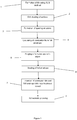
Figure 1 shows a schematic representation of a first embodiment of the first aspect; and -
Figure 2 is a sectional view of a gas turbine engine. - In
step 1, a combustor tile is formed of a high gamma prime nickel superalloy CM247LC using an additive layer manufacturing method. - In
step 2, the surface of the combustor file is grit-blasted to remove any surface irregularities. - In
step 3, a spacing structure is formed to surround the combustor tile. The spacing structure comprises a plurality of struts which project from the combustor tile. - In step 4, the combustor tile is enclosed in a foil envelope formed of 0.05mm thick 321 stainless steel foil. The foil is wrapped around the spacing structure such that the plurality of struts maintains a small spacing between the foil envelope and the combustor tile i.e. so that the foil envelope does not touch the combustor tile at any point. The foil envelope has an inlet opening at an uppermost edge and an outlet opening at a lowermost edge.
- In
step 5, the foil envelope is purged with argon by flowing argon into the inlet opening such that it passes through the foil envelope and out of the outlet opening. The argon purges the foil envelope of atmospheric air. - In
step 6, the outlet opening is sealed followed by sealing of the inlet opening. A series of small perforations are provided at the uppermost edge of the foil envelope to allow for venting of the foil envelope under pressure. - In
step 7, the combustor tile and foil envelope are placed within a heat treatment vessel and the heat treatment vessel is purged with argon. - Finally, in
step 8, the combustor tile is subjected to hot isostatic pressing. - The resulting combustor tile has been found to have a reduced susceptibility to cracking, even at locations which are highly stressed owing to their geometry.
- The foil envelope encloses the combustor tile within a reduced volume (compared to the heat treatment vessel) which can be more effectively purged with inert gas thus reducing the exposure of the highly stressed location to residual oxygen contained within the heat treatment vessel. Furthermore, the foil envelope is also sacrificed to improve the purity of the inert gas surrounding the envelope and which may gain access to the combustor tile e.g. through the venting perforations.
- With reference to
Figure 2 , a gas turbine engine is generally indicated at 10, having a principal androtational axis 11. Theengine 10 comprises, in axial flow series, anair intake 12, apropulsive fan 13, anintermediate pressure compressor 14, a high-pressure compressor 15,combustion equipment 16 comprising a plurality of combustor tiles manufactured as described above, a high-pressure turbine 17, anintermediate pressure turbine 18, a low-pressure turbine 19 and anexhaust nozzle 20. Anacelle 21 generally surrounds theengine 10 and defines both theintake 12 and theexhaust nozzle 20. - The
gas turbine engine 10 works in the conventional manner so that air entering theintake 12 is accelerated by thefan 13 to produce two air flows: a first air flow into theintermediate pressure compressor 14 and a second air flow which passes through abypass duct 22 to provide propulsive thrust. Theintermediate pressure compressor 14 compresses the air flow directed into it before delivering that air to thehigh pressure compressor 15 where further compression takes place. - The compressed air exhausted from the high-
pressure compressor 15 is directed into thecombustion equipment 16 where it is mixed with fuel and the mixture combusted. Thecombustion equipment 16 typically comprises an annular combustion chamber which is lined with the plurality of combustor tiles which can be manufactured according to the method described herein. - The resultant hot combustion products generated within the
combustion equipment 16 then expand through, and thereby drive the high, intermediate and low-pressure turbines nozzle 20 to provide additional propulsive thrust. The high 17, intermediate 18 and low 19 pressure turbines drive respectively thehigh pressure compressor 15,intermediate pressure compressor 14 andfan 13, each by suitable interconnecting shaft. - Other gas turbine engines to which the present disclosure may be applied may have alternative configurations. By way of example such engines may have an alternative number of interconnecting shafts (e.g. two) and/or an alternative number of compressors and/or turbines. Further the engine may comprise a gearbox provided in the drive train from a turbine to a compressor and/or fan.
- It will be understood that the invention is not limited to the embodiments above-described and various modifications and improvements can be made without departing from the concepts described herein. Except where mutually exclusive, any of the features may be employed separately or in combination with any other features and the disclosure extends to and includes all combinations and sub-combinations of one or more features described herein.
Claims (15)
- A method of heat treating a component, the method comprising:enclosing (4) at least part of the component in a foil envelope;purging (5) the envelope with an inert gas;sealing (6) the envelope; andheating the component.
- A method according to claim 1 further comprising manufacturing (1) the component using an ALM method prior to enclosing at least part of the component in the foil envelope.
- A method according to claim 2 comprising manufacturing the component from a nickel superalloy using an ALM method.
- A method according to claim 3 comprising manufacturing the component from a high gamma prime nickel superalloy using an ALM method.
- A method according to any one of claims 1 to 4 wherein the method further comprises grit blasting (2), surface finished or peening the surface of the component prior to enclosing it in the foil envelope.
- A method according to any one of the preceding claims wherein the component is formed of a first material and the foil envelope if formed of a second material which is more susceptible to reactive oxidation than the first material.
- A method according to claim 6 wherein the second material comprises an alloy having iron, aluminium, titanium, zirconium, or hafnium as a major component.
- A method according to claim 7 wherein the second material for forming the foil envelope is stainless steel.
- A method according to any one of the preceding claims comprising forming (3) a spacing structure surrounding the component/component part prior to enclosing it in the foil envelope.
- A method according to any one of the preceding claims comprising purging the foil envelope with an inert gas comprising argon.
- A method according to any one of the preceding claims comprising enclosing the component/component part within the foil envelope whilst providing an inert gas inlet opening at an uppermost edge of the foil envelope and an inert gas outlet opening at a lowermost edge of the foil envelope with an inert gas flow path extending therebetween.
- A method according to any one of the preceding claims wherein the component is heated under increased pressure.
- A method according to claim 12 comprising heating (8) the component using hot isostatic pressing.
- A method according to any one of the preceding claims comprising providing one or more vents in the envelope during or after sealing of the envelope.
- A method according to any one of the preceding claims wherein the component is a combustor tile for a gas turbine engine.
Applications Claiming Priority (1)
| Application Number | Priority Date | Filing Date | Title |
|---|---|---|---|
| GBGB1707895.7A GB201707895D0 (en) | 2017-05-17 | 2017-05-17 | Heat treatment method |
Publications (1)
| Publication Number | Publication Date |
|---|---|
| EP3403748A1 true EP3403748A1 (en) | 2018-11-21 |
Family
ID=59201668
Family Applications (1)
| Application Number | Title | Priority Date | Filing Date |
|---|---|---|---|
| EP18167754.3A Withdrawn EP3403748A1 (en) | 2017-05-17 | 2018-04-17 | Heat treatment method |
Country Status (3)
| Country | Link |
|---|---|
| US (1) | US20180361475A1 (en) |
| EP (1) | EP3403748A1 (en) |
| GB (1) | GB201707895D0 (en) |
Families Citing this family (1)
| Publication number | Priority date | Publication date | Assignee | Title |
|---|---|---|---|---|
| DE102022110345A1 (en) * | 2022-04-28 | 2023-11-02 | SLM Solutions Group AG | Method for removing powder from a three-dimensional workpiece produced by additive manufacturing |
Citations (5)
| Publication number | Priority date | Publication date | Assignee | Title |
|---|---|---|---|---|
| EP2669030A2 (en) * | 2012-05-30 | 2013-12-04 | Rolls-Royce plc | An apparatus and a method of manufacturing an article from powder |
| EP2692464A2 (en) * | 2012-08-01 | 2014-02-05 | Honeywell International Inc. | Titanium aluminide components and methods for manufacturing the same from articles formed by consolidation processes |
| US20140034626A1 (en) | 2012-08-06 | 2014-02-06 | Materials Solutions | Additive manufacturing |
| EP3072612A2 (en) * | 2015-03-27 | 2016-09-28 | General Electric Company | Component and method for fabricating a component |
| US20170021423A1 (en) * | 2014-04-02 | 2017-01-26 | Sandvik Intelectual Property Ab | Method for manufacturing a metallic component by pre-manufactured bodies |
Family Cites Families (5)
| Publication number | Priority date | Publication date | Assignee | Title |
|---|---|---|---|---|
| US5096518A (en) * | 1989-02-22 | 1992-03-17 | Kabushiki Kaisha Kobe Seiko Sho | Method for encapsulating material to be processed by hot or warm isostatic pressing |
| CN103551573B (en) * | 2013-10-22 | 2015-06-17 | 中国科学院金属研究所 | Previous particle boundary precipitation preventable high-temperature alloy powder hot isostatic pressing process |
| GB201502087D0 (en) * | 2015-02-09 | 2015-03-25 | Rolls Royce Plc | A method for the production on a three-dimensional product |
| GB201514801D0 (en) * | 2015-08-20 | 2015-10-07 | Rolls Royce Plc And Rolls Royce Deutschland Ltd & Co Kg | Method of manufacture of a turbine component |
| GB2549785A (en) * | 2016-04-29 | 2017-11-01 | Advanced Interactive Mat Science Ltd | Methods and apparatus for hot isostatic pressing |
-
2017
- 2017-05-17 GB GBGB1707895.7A patent/GB201707895D0/en not_active Ceased
-
2018
- 2018-04-17 EP EP18167754.3A patent/EP3403748A1/en not_active Withdrawn
- 2018-05-16 US US15/981,280 patent/US20180361475A1/en not_active Abandoned
Patent Citations (5)
| Publication number | Priority date | Publication date | Assignee | Title |
|---|---|---|---|---|
| EP2669030A2 (en) * | 2012-05-30 | 2013-12-04 | Rolls-Royce plc | An apparatus and a method of manufacturing an article from powder |
| EP2692464A2 (en) * | 2012-08-01 | 2014-02-05 | Honeywell International Inc. | Titanium aluminide components and methods for manufacturing the same from articles formed by consolidation processes |
| US20140034626A1 (en) | 2012-08-06 | 2014-02-06 | Materials Solutions | Additive manufacturing |
| US20170021423A1 (en) * | 2014-04-02 | 2017-01-26 | Sandvik Intelectual Property Ab | Method for manufacturing a metallic component by pre-manufactured bodies |
| EP3072612A2 (en) * | 2015-03-27 | 2016-09-28 | General Electric Company | Component and method for fabricating a component |
Also Published As
| Publication number | Publication date |
|---|---|
| US20180361475A1 (en) | 2018-12-20 |
| GB201707895D0 (en) | 2017-06-28 |
Similar Documents
| Publication | Publication Date | Title |
|---|---|---|
| US10865647B2 (en) | Turbo-machine impeller manufacturing | |
| Loh et al. | An overview of hot isostatic pressing | |
| US9950388B2 (en) | Method of producing an integrally bladed rotor for a turbomachine | |
| US20140037983A1 (en) | Titanium aluminide components and methods for manufacturing the same from articles formed by consolidation processes | |
| RU2552656C2 (en) | Compressor disc and method of its fabrication | |
| US10472971B2 (en) | Method of manufacture of a turbine component | |
| US8506836B2 (en) | Methods for manufacturing components from articles formed by additive-manufacturing processes | |
| US10702922B2 (en) | Method for manufacturing a metallic component by pre-manufactured bodies | |
| EP3192599B1 (en) | Method for removing partially sintered powder from internal passages of electron beam additive manufactured parts | |
| EP2050519B1 (en) | Shape Correcting Components | |
| EP2272665A1 (en) | Process for manufacturing foils, sheets and shaped parts from an alloy with titanium and aluminium as its main elements | |
| EP3277859B1 (en) | Dual alloy blade | |
| CN110116203A (en) | A method of eliminating Ni-base P/M Superalloy primary granule border | |
| CA2603503C (en) | Annular gas turbine engine case and method of manufacturing | |
| EP3403748A1 (en) | Heat treatment method | |
| US6939508B2 (en) | Method of manufacturing net-shaped bimetallic parts | |
| JP6216570B2 (en) | Component with cooling channel and manufacturing method | |
| US20170282454A1 (en) | Method of manufacture of a component | |
| CA2602994A1 (en) | Annular gas turbine engine case and method of manufacturing | |
| EP3415253A1 (en) | Heat treatment after alm of gamma'-strengthened nickel based superalloy component | |
| CN103506594A (en) | Precision casting method for engine vanes | |
| US10480528B2 (en) | Superplastic forming | |
| US11786973B2 (en) | Method for manufacturing a component using an additive process | |
| US20230094750A1 (en) | Ceramic matrix composite components with microstructure features | |
| US20170167008A1 (en) | Solution heat treatment method for manufacturing metallic components of a turbo machine |
Legal Events
| Date | Code | Title | Description |
|---|---|---|---|
| PUAI | Public reference made under article 153(3) epc to a published international application that has entered the european phase |
Free format text: ORIGINAL CODE: 0009012 |
|
| STAA | Information on the status of an ep patent application or granted ep patent |
Free format text: STATUS: THE APPLICATION HAS BEEN PUBLISHED |
|
| AK | Designated contracting states |
Kind code of ref document: A1 Designated state(s): AL AT BE BG CH CY CZ DE DK EE ES FI FR GB GR HR HU IE IS IT LI LT LU LV MC MK MT NL NO PL PT RO RS SE SI SK SM TR |
|
| AX | Request for extension of the european patent |
Extension state: BA ME |
|
| STAA | Information on the status of an ep patent application or granted ep patent |
Free format text: STATUS: REQUEST FOR EXAMINATION WAS MADE |
|
| 17P | Request for examination filed |
Effective date: 20190122 |
|
| RBV | Designated contracting states (corrected) |
Designated state(s): AL AT BE BG CH CY CZ DE DK EE ES FI FR GB GR HR HU IE IS IT LI LT LU LV MC MK MT NL NO PL PT RO RS SE SI SK SM TR |
|
| RAP1 | Party data changed (applicant data changed or rights of an application transferred) |
Owner name: ROLLS-ROYCE PLC |
|
| STAA | Information on the status of an ep patent application or granted ep patent |
Free format text: STATUS: EXAMINATION IS IN PROGRESS |
|
| 17Q | First examination report despatched |
Effective date: 20200317 |
|
| STAA | Information on the status of an ep patent application or granted ep patent |
Free format text: STATUS: THE APPLICATION HAS BEEN WITHDRAWN |
|
| 18W | Application withdrawn |
Effective date: 20200603 |