EP3403600A1 - Surgical device for osteotomy - Google Patents
Surgical device for osteotomy Download PDFInfo
- Publication number
- EP3403600A1 EP3403600A1 EP18177577.6A EP18177577A EP3403600A1 EP 3403600 A1 EP3403600 A1 EP 3403600A1 EP 18177577 A EP18177577 A EP 18177577A EP 3403600 A1 EP3403600 A1 EP 3403600A1
- Authority
- EP
- European Patent Office
- Prior art keywords
- osteotomy
- body component
- guide edge
- correcting perforation
- surgical device
- Prior art date
- Legal status (The legal status is an assumption and is not a legal conclusion. Google has not performed a legal analysis and makes no representation as to the accuracy of the status listed.)
- Granted
Links
Images





Classifications
-
- A—HUMAN NECESSITIES
- A61—MEDICAL OR VETERINARY SCIENCE; HYGIENE
- A61B—DIAGNOSIS; SURGERY; IDENTIFICATION
- A61B17/00—Surgical instruments, devices or methods
- A61B17/16—Instruments for performing osteoclasis; Drills or chisels for bones; Trepans
- A61B17/1657—Bone breaking devices
-
- A—HUMAN NECESSITIES
- A61—MEDICAL OR VETERINARY SCIENCE; HYGIENE
- A61B—DIAGNOSIS; SURGERY; IDENTIFICATION
- A61B17/00—Surgical instruments, devices or methods
- A61B17/14—Surgical saws
- A61B17/15—Guides therefor
- A61B17/151—Guides therefor for corrective osteotomy
-
- A—HUMAN NECESSITIES
- A61—MEDICAL OR VETERINARY SCIENCE; HYGIENE
- A61B—DIAGNOSIS; SURGERY; IDENTIFICATION
- A61B17/00—Surgical instruments, devices or methods
- A61B17/14—Surgical saws
- A61B17/15—Guides therefor
- A61B17/154—Guides therefor for preparing bone for knee prosthesis
- A61B17/155—Cutting femur
-
- A—HUMAN NECESSITIES
- A61—MEDICAL OR VETERINARY SCIENCE; HYGIENE
- A61B—DIAGNOSIS; SURGERY; IDENTIFICATION
- A61B17/00—Surgical instruments, devices or methods
- A61B17/14—Surgical saws
- A61B17/15—Guides therefor
- A61B17/154—Guides therefor for preparing bone for knee prosthesis
- A61B17/157—Cutting tibia
Definitions
- the present invention relates to a surgical device for osteotomy. More specifically, it is related to a surgical device of osteotomies and custom-made for the specific patient.
- the knee is one of the most weight-bearing joints in the body. If the knee had sports injuries or into the middle age, it is likely to cause articular cartilage wear and resulting in a symptom of knee pain. The daily activity is limited. This is the cause of the degenerative joint disease.
- High tibial osteotomy is a surgery to realign the biomechanical axis by cutting and opening at the medial proximal tibia, sometimes the opening gap needs to be filled with bone grafts. Then the osteomized tibia is fixed by a bone plate. This surgical procedure avoids bone resection and preserves the knee joint. It is a better choice for the patient with medial knee pain.
- the present invention provides a surgical device for osteotomy. It provides a guide for saw blade to perform high tibial osteotomy, but not limited to, the surgical device for osteotomy can be used for other bones, such as: femur, fibula, humerus, ulna, radius, clavicle, scapula and so on.
- the tibia is described in the preferred embodiment of the present invention.
- the exterior design has features that can assist the clinician to determine the cutting position, direction and depth, the opening height precisely. Compared with conventional free-hand surgery, the present invention is more precise, time saving, easy learning, and with low exposure of radiation. Each device is custom-made for the patient.
- the present invention provides a surgical device for osteotomy.
- the surgical device for osteotomy is used to guide a saw blade to perform high tibial osteotomy, but not limited to, it can also be applied to other bones.
- the aforementioned tibia is defined as a first cutting position and a second cutting position by the surgical device for the osteotomy.
- the surgical device comprises: a first body component, a second body component, and a plurality of fixing slots.
- first body component is disposed above the first cutting position and has a side guide edge, an upper guide edge and a first correcting perforation, the first correcting perforation being provided on the upper guide edge;
- second body component is disposed below the first cutting position or below the upper guide edge and has a lower guide edge and a second correcting perforation.
- the lower guide edge is disposed below the upper guide edge.
- the second correcting perforation is provided on the lower guide edge.
- the surfaces of the first body component and the second body component have the plurality of fixing slots or holes for fixing the surgical device on the bone surface.
- a guide groove is formed between the upper guide edge and the lower guide edge for guiding the saw blade to the first cutting position.
- the side guide edge is used to guide the saw blade to the second cutting position.
- the upper guide edge, the lower guide edge and the side guide edge are employed to form the cutting track.
- the saw blade cuts the tibia according to the first cutting position and the second cutting position, thereby operating high tibial osteotomy.
- the first correcting perforation is connected to the first body component by a first bar; the second correcting perforation is connected to the second body component by a second bar.
- the surgical device for osteotomy further comprises a hinge pin guide component disposed on the surface of the second body component. It comprises a third bar extending to the rear of the second cutting position or the rear of the guide groove and a third correcting perforation.
- the third correcting perforation fits with the preoperative hinge axis for high tibial osteotomy as a rotation axis when the tibia is opened.
- the present invention also provides a surgical device for osteotomy that is used to guide a saw blade to perform high tibial osteotomy.
- the aforementioned tibia is defined as a first cutting position and a second cutting position by the surgical device for osteotomy.
- the surgical device for osteotomy comprises: a first body component, a second body component and a plurality of fixing slots.
- the first body component is disposed above the first cutting position and has a side guide edge, an upper guide edge and a first correcting perforation, the first correcting perforation is connected to the first body component by a first bar.
- the second body component is disposed below the first cutting position or below the upper guide edge and has a lower guide edge and a second correcting perforation.
- the lower guide edge is disposed below the upper guide edge.
- the second correcting perforation is connected to the second body component by a second bar.
- the surfaces of the first body component and the second body component have the plurality of fixing slots for fixing the surgical device on
- a guide groove is formed between the upper guide edge and the lower guide edge for guiding the saw blade to the first cutting position.
- the side guide edge is used to guide the saw blade to the second cutting position.
- the upper guide edge, the lower guide edge and the side guide edge are used to form the cutting track.
- the saw blade cuts the tibia according to the first cutting position and the second cutting position, thereby operating high tibial osteotomy.
- the surgical device for osteotomy further comprises a hinge pin guide component disposed on the surface of the second body component. It comprises a third correcting perforation extending to the rear of the second cutting position.
- the third correcting perforation fits with the preoperative hinge axis for high tibial osteotomy as a rotation axis and ensuring the cutting depth when the tibia is opened.
- the surgical device for osteotomy is manufactured by three-dimensional printing (3D printing) according to the patient's skeletal image data, the optimal cutting position is evaluated preoperatively.
- the device can fit well with the patient's bone.
- the surgeon can perform the first cutting position under the guide groove specified by the device.
- the guide groove allows the surgeon to perform the osteotomy accurately. It also provides a reference for calculating the cutting angle and depth.
- the side guide edge provides the reference for the second cut. Not only improving the surgical accuracy and efficiency, but the present invention also standardizes the whole surgical procedure for surgeons.
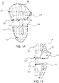
- FIG. 1A illustrates a front view of an embodiment of the present invention when implemented.
- FIG. 1B illustrates a side view of an embodiment of the present invention when implemented.
- FIG. 2 illustrates the position at which the tibia is to be cut when the present invention is practiced.
- the present invention provides a surgical device for osteotomy 1 which can be used in various osteotomy, correction or reduction surgery.
- the surgical device for osteotomy 1 can be used for various bones of the human body, such as: tibia B, femur D, fibula, humerus, ulna, radius, clavicle, scapula, etc., but not limited to.
- it provides a guide for saw blade to perform high tibial osteotomy of a tibia B.
- the first cutting position C1 and a second cutting position C2 on tibia B are defined by the surgical device for osteotomy 1.
- the surgical device for osteotomy 1 comprises: a first body component 12, a second body component 14, and a plurality of fixing slots 16.
- first body component 12 is disposed above the first cutting position C1 and has a side guide edge 121 and an upper guide edge 122.
- the second body component 14 is disposed below the first cutting position C1 or below the upper guide edge 122 and has a lower guide edge 141.
- the lower guide edge 141 is disposed below the upper guide edge 122.
- the surfaces of the first body component 12 and the second body component 14 have the plurality of fixing slots 16.
- the surgical device for osteotomy 1 is fixed on the surface of the tibia B by inserting a plurality of fixing pins into the plurality of fixing slots 16.
- the upper guide edge 122 and the lower guide edge 141 extend outwardly from the first body component 12 and the second body component 14, respectively.
- a guide groove 50 is formed between the upper guide edge 122 and the lower guide edge 141 for guiding the saw blade to the first cutting position C1.
- the side guide edge 121 is used to guide the saw blade to the second cutting position C2.
- the upper guide edge 122, the lower guide edge 141 and the side guide edge 121 are used to form the cutting track.
- the saw blade cuts the tibia B according to the first cutting position C1 and the second cutting position C2, thereby operating high tibial osteotomy.
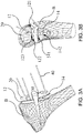
- FIG. 3A illustrates a back view of an embodiment of the present invention when implemented in a tibia.
- FIG. 3B illustrates a side view of an embodiment of the present invention when implemented in a tibia.
- the first body component 12 further comprises a first correcting perforation 123.
- the first correcting perforation 123 is provided on the upper guide edge 122.
- the second body component 14 further comprises a second correcting perforation 142.
- the second correcting perforation 142 is provided on the lower guide edge 141.
- the first correcting perforation 123 and the second correcting perforation 142 are designed to confirm the correction angle which is opened intraoperatively in high tibial osteotomy. For this reason, there is a regulative angle L between the first hole axis A1 of the first correcting perforation 123 and the second hole axis A2 of the second correcting perforation 142 (the hole axes A1, A2 and the regulative angle are plotted in FIG. 5 ). In high tibial osteotomy, a gap of the osteotomy has a preoperative planning correction angle M.
- the first hole axis A1 of the first correcting perforation 123 and the second hole axis A2 of the second correcting perforation 142 can coincide.
- An aligning bar 20 passes through the first correcting perforation 123 and the second correcting perforation 142 to ensure the opening has achieved the correction angle.
- the size of the aforementioned correction angle is based on the correction angle M that the tibia B needs to open in high tibial osteotomy.
- the angle between the axis of the first correcting perforation and the axis of the second correcting perforation is determined according to the desired correction angle M and it is made.
- the aligning bar 20 can be inserted between the first correcting perforation 123 and the second correcting perforation 142 only when the tibia B is opened to the angle of preoperative planning by the first body component 12 and the second body component 14.
- FIG. 4A illustrates a front view of an embodiment of the present invention before surgical process.
- FIG. 4B illustrates a side view of an embodiment of the present invention before surgical process.
- the first body component 12 and the second body component 14 are made by 3D printing. Since the first body component 12 and the second body component 14 need to be connected with each other in the surgery before the sawing procedure. So, the surgical device for osteotomy 1 further comprises a connecting component 18. Before the sawing procedure, the first body component 12 and the second body component 14 are connected by component 18 to ensure the sufficient area for attaching the bone surface.
- the first body component 12 and the second body component 14 are fixed to the patient's tibia before the sawing procedure of high tibial osteotomy, and then the connecting component 18 is removed.
- the present invention is not limited to this, the first body component 12 and the second body component 14 may be manufactured in an integrally formed manner. At this time, there is a connecting part between the upper guide edge 122 and the lower guide edge 141, then the connecting component 18 is not necessary. When the osteotomy is performed, the surgeon can directly cut the connecting part with the bone saw.
- FIG. 5 illustrates another embodiment of the present invention.
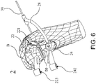
- FIG. 6 illustrates another embodiment of the present invention when implemented.
- the present invention further provides a surgical device for osteotomy 2 which can be used in various osteotomy, correction or reduction surgery.
- the surgical device for osteotomy 2 can be used for various bones of the human body, such as: tibia B, femur D, fibula, humerus, ulna, radius, clavicle, scapula, etc., but not limited to.
- it provides a guide for saw blade to perform high tibial osteotomy of a tibia B.
- the first cutting position C1 and a second cutting position C2 on tibia B are defined by the surgical device for osteotomy 2.
- the surgical device for osteotomy 2 comprises: a first body component 22, a second body component 24, a plurality of fixing slots 26 and a hinge pin guide component 28.
- the first body component 22 and the second body component 24 are connected by a connecting part.
- the surgeon can directly cut the connecting part with the bone saw, but not limited to.
- the first body component 22 and the second body component 24 can be directly used without using the connecting part.
- the first body component 22 and the second body component 24 may be connected in other forms.
- first body component 22 is disposed above the first cutting position C1 and has a side guide edge 221, an upper guide edge 222 and a first correcting perforation 223.
- the first correcting perforation 223 is connected to the first body component 22 by a first bar 224.
- the second body component 24 is disposed below the first cutting position C1 or below the upper guide edge 222 and has a lower guide edge 241 and a second correcting perforation 242.
- the lower guide edge 241 is disposed below the upper guide edge 222.
- a guide groove 50 is formed between the upper guide edge 222 and the lower guide edge 241.
- the second correcting perforation 242 is connected to the second body component 24 by a second bar 243.
- the surfaces of the first body component 22 and the second body component 24 have the plurality of fixing slots 26.
- the surgical device for osteotomy 2 is fixed on the surface of the tibia B by inserting a plurality of fixing pins 40 into the plurality of fixing slots 26.
- a hinge pin guide component 28 is disposed on the surface of the second body component 24, it comprises a third correcting perforation 281 extending to the rear of the second cutting position C2 or the rear of the guide groove 50.
- the third correcting perforation 281 fits with the preoperative hinge axis 30 for high tibial osteotomy as a rotation axis when the tibia B is opened.
- the position and direction of the hinge can be guaranteed as the preoperative planning intraoperatively.
- the saw blade When the saw blade has reached the pre-planned cutting depth, it will be blocked by the hinge pin on the hinge axis 30 to ensure the sawing depth and improve the surgical accuracy.
- pre-drilled hole can distribute the stress and avoid the fracture of lateral cortex of tibia B while opening the gap.
- the hinge pin guide component 28 and the second body component 24 are integrally formed or combined.
- the upper guide edge 222 and the lower guide edge 241 extend outwardly from the first body component 22 and the second body component 24, respectively.
- a guide groove 50 is formed between the upper guide edge 222 and the lower guide edge 241 for guiding the saw blade to the first cutting position C1.
- the side guide edge 221 is used to guide the saw blade to the second cutting position C2.
- the upper guide edge 222, the lower guide edge 241 and the side guide edge 221 are used to form the cutting track.
- the saw blade cuts the tibia B according to the first cutting position C1 and the second cutting position C2, thereby operating high tibial osteotomy.
- the first correcting perforation 223 and the second correcting perforation 242 are designed to confirm the correction angle which is opened intraoperatively in high tibial osteotomy. For this reason, there is a regulative angle L between the first hole axis A1 of the first correcting perforation 223 and the second hole axis A2 of the second correcting perforation 242.
- the tibia B is opened by the first body component 22 and the second body component 24 with the correction angle that is the same as the preoperative planning, the first hole axis A1 of the first correcting perforation 223 and the second hole axis A2 of the second correcting perforation 242 can coincide.
- An aligning bar 20 passes through the first correcting perforation 223 and the second correcting perforation 242 to ensure the opening has achieved the correction angle.
- the size of the aforementioned regulative angle L is based on the correction angle that the tibia B needs to open in high tibial osteotomy.
- the size of the regulative angle L is determined according to the desired correction angle and it is made.
- the aligning bar 20 can be inserted between the first correcting perforation 223 and the second correcting perforation 242 only when the tibia B is opened to the angle of preoperative planning by the first body component 22 and the second body component 24.
- FIG. 2 Please refer to FIG. 2 , FIG. 3A , FIG. 3B and FIG. 7 .
- the surgical devices for osteotomy 1, 2 attached to the tibial position are located in the calf of human body and close to the knee on the medial side of the proximal end.
- the scope of its attachment is not limited to this, it can also be attached to other positions of the other bones.
- the picture shows the positive side of FIG. 2 is pointing to the inside of human body.
- the left side of FIG. 2 points to the back of human body.
- FIG. 3A and FIG. 3B correspond to the surgical device for osteotomy 1.
- FIG. 7 illustrates a front view of another embodiment of the present invention when implemented and corresponds to the surgical device for osteotomy 2.
- the present invention of the surgical devices for osteotomy 1, 2 are based on the tibial image information provided by patients with degenerative joint disease before surgery.
- the model of tibia B was established using computer software.
- the position of the first cutting position C1 and the second cutting position C2 is determined according to the model of tibia B.
- the overall structure of the surgical devices for osteotomy 1, 2 are custom-made. Wherein the surgical devices for osteotomy 1, 2 are designed to be able to fit well with the surface of the patient's tibia B, and then the three-dimensional printing technique is used to construct an integrally formed or combined solid instrument.
- the surgeon inserts the saw blade and starts cutting according to the first cutting position C1 guided by the upper guide edge 122, 222 and the lower guide edge 141, 241 of the surgical devices for osteotomy 1, 2.
- the surgeon can use the upper guide edges 122, 222 and the lower guide edges 141, 241 as a reference for the calculation of the cutting depth.
- the surgeons can use the naked eye to confirm whether the sawing depth of the saw blade has reached the preset depth.
- the saw blade keeps cutting along the upper guide edge 122, 222 and the lower guide edge 141, 241 to the inside of the human body until the predetermined depth is achieved. Cut off part of the tibia B. Along the second cutting position C2 guided by the side guide edges 121, 221 to create an ascending cut. After the cutting, the first cutting position C1 of the tibia B is opened to the preoperative planning correction angle M in the case where the surgical devices for osteotomy 1, 2 are fixed to the tibia B. The aligning bar 20 is then inserted through the first correcting perforations 123, 223 and the second correcting perforations 142, 242. After confirming the correction angle of the osteotomy of the tibia B, the gap can be fixed with the implant.
- FIG. 8A illustrates a side view of the other embodiment of the present invention when implemented.
- FIG. 8B illustrates the position at which the femur D is to be cut when the present invention is practiced.
- FIG. 9A illustrates a front view of the other embodiment of the present invention when implemented.
- FIG. 9B illustrates a side view of the other embodiment of the present invention when implemented.
- the present invention further provides a surgical device for osteotomy 3 which can be used in various osteotomy, correction or reduction surgery.
- the surgical device for osteotomy 3 can be used for various bones of the human body, such as: tibia B, femur D, fibula, humerus, ulna, radius, clavicle, scapula, etc., but not limited to.
- it provides a guide for saw blade to perform the distal femoral osteotomy (DFO) of a femur D.
- the surgical device for osteotomy 3 comprises: a first body component 32, a second body component 34 and a plurality of fixing slots 36.
- the first body component 32 and the second body component 34 are connected by a connecting part.
- FIG. 8A to FIG. 9B shows the femur is the body's left thigh (femur) near the knee.
- the scope of application is not limited thereto, it can also be applied to other positions of other bones.
- the aforementioned femur D is defined as a third cutting position C3 by the surgical device for osteotomy 3.
- the first body component 32 is disposed above the third cutting position C3 and has an upper guide edge 321 and a first correcting perforation 322, the first correcting perforation 322 is connected to the first body component 32 by a first bar 323.
- the second body component 34 is disposed below the third cutting position C3 or below the upper guide edge 321 and has a lower guide edge 341 and a second correcting perforation 342.
- the lower guide edge 341 is disposed below the upper guide edge 321.
- the second correcting perforation 342 is connected to the second body component 34 by a second bar 343.
- the surfaces of the first body component 32 and the second body component 34 have the plurality of fixing slots 36, and the surgical device for osteotomy 3 is fixed on the surface of the femur D by inserting a plurality of fixing pins 40 into the plurality of fixing slots 36.
- the upper guide edge 321 and the lower guide edge 341 extend outwardly from the first body component 32 and the second body component 34, respectively.
- a guide groove 50 is formed between the upper guide edge 321 and the lower guide edge 341 for guiding the saw blade to the third cutting position C3.
- the upper guide edge 321 and the lower guide edge 341 are used to form the cutting track.
- the saw blade cuts the femur D according to the third cutting position C3, thereby operating the distal femoral osteotomy.
- the first correcting perforation 322 and the second correcting perforation 342 are designed to confirm the correction angle at which the femoral opening is opened in the distal femoral osteotomy. For this reason, there is a regulative angle N between the first hole axis A1 of the first correcting perforation 322 and the second hole axis A2 of the second correcting perforation 342. In the distal femoral osteotomy, a gap of the osteotomy has a preoperative planning correction angle.
- the first hole axis A1 of the first correcting perforation 322 and the second hole axis A2 of the second correcting perforation 342 can coincide.
- An aligning bar 20 passes through the first correcting perforation 322 and the second correcting perforation 342 to ensure the opening has achieved the correction angle.
- the size of the aforementioned regulative angle N is based on the correction angle that the femur D needs to open in the distal femoral osteotomy.
- the size of the regulative angle N is determined according to the desired correction angle and it is made.
- the aligning bar 20 can be inserted between the first correcting perforation 322 and the second correcting perforation 342 only when the femur D is opened to the angle of preoperative planning by the first body component 32 and the second body component 34.
- FIG. 8A, FIG 8B , FIG. 9A and FIG. 9B Please refer to FIG. 8A, FIG 8B , FIG. 9A and FIG. 9B .
- the surgical device for osteotomy 3 attached to the femoral position is located in the left thigh of human body and close to lateral distal end of the knee.
- the scope of application is not limited thereto, it can also be applied to other positions of other bones.
- the picture shows the positive side of FIG. 8A and FIG. 8B is pointing to the human body.
- the left side of FIG. 8A and FIG. 8B points to the front of the human body.
- the present invention of the surgical device for osteotomy 3 is based on the femoral image information provided by patients with degenerative joint disease before surgery.
- the model of femur D was established using computer software.
- the position of the third cutting position C3 is determined according to the model of femur D.
- the overall structure of the surgical device for osteotomy 3 is custom-made. Wherein the surgical device for osteotomy 3 is designed to be able to fit well with the surface of the patient's femur D, and then the three-dimensional printing technique is used to construct an integrally formed or combined solid instrument.
- FIG. 9A the figure shows the completed cutting track E on the third cutting position C3.
- the surgeon inserts the saw blade and starts cutting according to the third cutting position C3 guided by the upper guide edge 321 and the lower guide edge 341 of the surgical device for osteotomy 3.
- the surgeon can use the upper guide edges 321 and the lower guide edges 341 as a reference for the calculation of the sawing depth.
- surgeons can use the naked eye to confirm whether the sawing depth of the saw blade has reached the preset depth.
- the saw blade keeps cutting along the upper guide edge 321 and the lower guide edge 341. Then, it cut off part of the femur D.
- the third cutting position C3 of the femur D is opened to the preoperative planning correction angle in the case where the surgical device for osteotomy 3 is fixed to the femur D.
- the aligning bar 20 is then inserted through the first correcting perforation 322 and the second correcting perforation 342. After confirming the correction angle of the osteotomy of the femur D, the gap can be fixed with the implant.
- the present invention provides a surgical device for osteotomy 1, 2, 3.
- it is custom-made to the skeletal image information collected from patients with degenerative joint disease before surgery.
- the first cutting position C1 is designated by the upper guide edge 122, 222 and the lower guide edge 141, 241 as a reference point for the cutting depth. So that the surgeon can easily control the cutting depth.
- the second cutting position C2 is designated by the side guide edge 121, 221 for osteotomy.
- the third cutting position C3 is designated by the upper guide edge 321 and the lower guide edge 341 as a reference point for the cutting depth. So that the surgeon can easily control the cutting depth.
- the present invention can avoid ligament injury during surgery. It can also be created to resist the rotation of the bones due to the movement.
- the present invention is designed according to a preoperative planning so that the surgical procedure can be simplified.
- the surgical device for osteotomy 1, 2, 3 is manufactured by three-dimensional printing according to the patient's skeletal image data, and the optimal cutting position is evaluated preoperatively.
- the device can fit well with the patient's bones.
- the surgeon can perform the first cutting position C1 or the third cutting position C3 under the guide groove 50 specified by the device.
- the guide groove 50 allows the surgeon to perform the osteotomy accurately. It also provides a reference for calculating the cutting angle and depth.
- the side guide edge 121, 221 provides the reference for the second cutting position C2. Not only improving the surgical accuracy and efficiency, but the present invention also standardizes the whole surgical procedure for surgeons.
Landscapes
- Health & Medical Sciences (AREA)
- Surgery (AREA)
- Life Sciences & Earth Sciences (AREA)
- Biomedical Technology (AREA)
- Medical Informatics (AREA)
- Oral & Maxillofacial Surgery (AREA)
- Dentistry (AREA)
- Engineering & Computer Science (AREA)
- Orthopedic Medicine & Surgery (AREA)
- Heart & Thoracic Surgery (AREA)
- Nuclear Medicine, Radiotherapy & Molecular Imaging (AREA)
- Molecular Biology (AREA)
- Animal Behavior & Ethology (AREA)
- General Health & Medical Sciences (AREA)
- Public Health (AREA)
- Veterinary Medicine (AREA)
- Surgical Instruments (AREA)
- Prostheses (AREA)
Abstract

Description
- The present invention relates to a surgical device for osteotomy. More specifically, it is related to a surgical device of osteotomies and custom-made for the specific patient.
- The knee is one of the most weight-bearing joints in the body. If the knee had sports injuries or into the middle age, it is likely to cause articular cartilage wear and resulting in a symptom of knee pain. The daily activity is limited. This is the cause of the degenerative joint disease.
- Common treatment is artificial joint arthroplasty that involves large bone resection for the fixation of the metal and polymer implants. Due to the wear of the implant, the maximum duration of the artificial joint replacement is only twenty years, and may cause complications like infection, osteolysis and osteoporosis, which will need revision surgery. Furthermore, some patients with early degenerative joint disease, in fact, only wear the medial articular surface. It is not necessary to remove the entire joint for arthroplasty. For example, high tibial osteotomy is commonly used for patients with medial degenerative knee osteoarthritis.
- High tibial osteotomy is a surgery to realign the biomechanical axis by cutting and opening at the medial proximal tibia, sometimes the opening gap needs to be filled with bone grafts. Then the osteomized tibia is fixed by a bone plate. This surgical procedure avoids bone resection and preserves the knee joint. It is a better choice for the patient with medial knee pain.
- However, high tibial osteotomy requires cutting and opening at the proximal tibia. The cutting position, direction, depth, and surgical opening height are important and should be carefully planned, but are difficult to perform precisely. Currently, the above-mentioned parameters can only checked intraoperatively by X-ray and the surgeon's experience. The amount of the correction of biomechanical axis and above-mentioned parameters are all different for each patient, thus the design of surgical instruments must be considered as well.
- In view of the foregoing problems, the present invention provides a surgical device for osteotomy. It provides a guide for saw blade to perform high tibial osteotomy, but not limited to, the surgical device for osteotomy can be used for other bones, such as: femur, fibula, humerus, ulna, radius, clavicle, scapula and so on. The tibia is described in the preferred embodiment of the present invention. The exterior design has features that can assist the clinician to determine the cutting position, direction and depth, the opening height precisely. Compared with conventional free-hand surgery, the present invention is more precise, time saving, easy learning, and with low exposure of radiation. Each device is custom-made for the patient.
- The present invention provides a surgical device for osteotomy. The surgical device for osteotomy is used to guide a saw blade to perform high tibial osteotomy, but not limited to, it can also be applied to other bones. The aforementioned tibia is defined as a first cutting position and a second cutting position by the surgical device for the osteotomy. The surgical device comprises: a first body component, a second body component, and a plurality of fixing slots. Wherein the first body component is disposed above the first cutting position and has a side guide edge, an upper guide edge and a first correcting perforation, the first correcting perforation being provided on the upper guide edge; the second body component is disposed below the first cutting position or below the upper guide edge and has a lower guide edge and a second correcting perforation. The lower guide edge is disposed below the upper guide edge. The second correcting perforation is provided on the lower guide edge. The surfaces of the first body component and the second body component have the plurality of fixing slots or holes for fixing the surgical device on the bone surface.
- Wherein a guide groove is formed between the upper guide edge and the lower guide edge for guiding the saw blade to the first cutting position. The side guide edge is used to guide the saw blade to the second cutting position. The upper guide edge, the lower guide edge and the side guide edge are employed to form the cutting track. The saw blade cuts the tibia according to the first cutting position and the second cutting position, thereby operating high tibial osteotomy. There is a regulative angle between the first hole axis of the first correcting perforation and the second hole axis of the second correcting perforation. When the opening of the gap achieves the same angle as the preoperative planning, the first hole axis of the first correcting perforation and the second hole axis of the second correcting perforation will coincide.
- In another embodiment of the present invention, the first correcting perforation is connected to the first body component by a first bar; the second correcting perforation is connected to the second body component by a second bar.
- In another embodiment of the present invention, the surgical device for osteotomy further comprises a hinge pin guide component disposed on the surface of the second body component. It comprises a third bar extending to the rear of the second cutting position or the rear of the guide groove and a third correcting perforation. The third correcting perforation fits with the preoperative hinge axis for high tibial osteotomy as a rotation axis when the tibia is opened. By inserting the pin as a hinge axis, the position and direction of the hinge can be guaranteed as the preoperative planning intraoperatively. When the saw blade has reached the pre-planned cutting depth, it will be blocked by the hinge pin, thus ensuring the sawing depth and increasing the surgical accuracy. In addition, the pre-drilled hole can distribute the stress and avoid the fracture of lateral cortex while opening the gap.
- The present invention also provides a surgical device for osteotomy that is used to guide a saw blade to perform high tibial osteotomy. The aforementioned tibia is defined as a first cutting position and a second cutting position by the surgical device for osteotomy. The surgical device for osteotomy comprises: a first body component, a second body component and a plurality of fixing slots. Wherein the first body component is disposed above the first cutting position and has a side guide edge, an upper guide edge and a first correcting perforation, the first correcting perforation is connected to the first body component by a first bar. The second body component is disposed below the first cutting position or below the upper guide edge and has a lower guide edge and a second correcting perforation. The lower guide edge is disposed below the upper guide edge. The second correcting perforation is connected to the second body component by a second bar. The surfaces of the first body component and the second body component have the plurality of fixing slots for fixing the surgical device on the bone surface.
- Wherein a guide groove is formed between the upper guide edge and the lower guide edge for guiding the saw blade to the first cutting position. The side guide edge is used to guide the saw blade to the second cutting position. The upper guide edge, the lower guide edge and the side guide edge are used to form the cutting track. The saw blade cuts the tibia according to the first cutting position and the second cutting position, thereby operating high tibial osteotomy. There is a regulative angle between the first hole axis of the first correcting perforation and the second hole axis of the second correcting perforation. When the opening of the gap achieves the same angle as the preoperative planning, the first hole axis of the first correcting perforation and the second hole axis of the second correcting perforation will coincide.
- In an embodiment of the present invention, the surgical device for osteotomy further comprises a hinge pin guide component disposed on the surface of the second body component. It comprises a third correcting perforation extending to the rear of the second cutting position. The third correcting perforation fits with the preoperative hinge axis for high tibial osteotomy as a rotation axis and ensuring the cutting depth when the tibia is opened.
- Compared with the conventional technique, the surgical device for osteotomy is manufactured by three-dimensional printing (3D printing) according to the patient's skeletal image data, the optimal cutting position is evaluated preoperatively. The device can fit well with the patient's bone. The surgeon can perform the first cutting position under the guide groove specified by the device. The guide groove allows the surgeon to perform the osteotomy accurately. It also provides a reference for calculating the cutting angle and depth. The side guide edge provides the reference for the second cut. Not only improving the surgical accuracy and efficiency, but the present invention also standardizes the whole surgical procedure for surgeons.
-
-
FIG. 1A illustrates a front view of an embodiment of the present invention when implemented. -
FIG. 1B illustrates a side view of an embodiment of the present invention when implemented. -
FIG. 2 illustrates the position at which the tibia is to be cut when the present invention is practiced. -
FIG. 3A illustrates a back view of an embodiment of the present invention when implemented in a tibia. -
FIG. 3B illustrates a side view of an embodiment of the present invention when implemented in a tibia. -
FIG. 4A illustrates a front view of an embodiment of the present invention before surgical process. -
FIG. 4B illustrates a side view of an embodiment of the present invention before surgical process. -
FIG. 5 illustrates another embodiment of the present invention. -
FIG. 6 illustrates another embodiment of the present invention when implemented. -
FIG. 7 illustrates a front view of another embodiment of the present invention when implemented. -
FIG. 8A illustrates a side view of the other embodiment of the present invention when implemented. -
FIG. 8B illustrates the position at which the femur is to be cut when the present invention is practiced. -
FIG. 9A illustrates a front view of the other embodiment of the present invention when implemented. -
FIG. 9B illustrates a side view of the other embodiment of the present invention when implemented. - Some preferred embodiments of the present invention will now be described in greater detail. However, it should be recognized that the preferred embodiments of the present invention are provided for illustration rather than limiting the present invention.
- In addition, the present invention can be practiced in a wide range of other embodiments besides those explicitly described, and the scope of the present invention is not expressly limited except as specified in the accompanying claims. The layout of components may be more complicated in practice.
- Furthermore, the greater number or lesser number mentioned in the present specification is included in the number itself. It is to be understood that this specification discloses certain methods and processes for carrying out the functions, there are a variety of structures related to the disclosed structures that perform the same function. The above-mentioned structures generally achieve the same result.
- Hereinafter, preferred embodiments of the present invention will be described in detail to fully illustrate the features, spirit and advantages of the present invention.
- Please refer to
FIG. 1A, FIG. 1B andFIG. 2 .FIG. 1A illustrates a front view of an embodiment of the present invention when implemented.FIG. 1B illustrates a side view of an embodiment of the present invention when implemented.FIG. 2 illustrates the position at which the tibia is to be cut when the present invention is practiced. - The present invention provides a surgical device for
osteotomy 1 which can be used in various osteotomy, correction or reduction surgery. The surgical device forosteotomy 1 can be used for various bones of the human body, such as: tibia B, femur D, fibula, humerus, ulna, radius, clavicle, scapula, etc., but not limited to. In the present embodiment, it provides a guide for saw blade to perform high tibial osteotomy of a tibia B. The first cutting position C1 and a second cutting position C2 on tibia B are defined by the surgical device forosteotomy 1. The surgical device forosteotomy 1 comprises: afirst body component 12, asecond body component 14, and a plurality of fixingslots 16. Wherein thefirst body component 12 is disposed above the first cutting position C1 and has aside guide edge 121 and anupper guide edge 122. Thesecond body component 14 is disposed below the first cutting position C1 or below theupper guide edge 122 and has alower guide edge 141. Thelower guide edge 141 is disposed below theupper guide edge 122. The surfaces of thefirst body component 12 and thesecond body component 14 have the plurality of fixingslots 16. The surgical device forosteotomy 1 is fixed on the surface of the tibia B by inserting a plurality of fixing pins into the plurality of fixingslots 16. - Wherein the
upper guide edge 122 and thelower guide edge 141 extend outwardly from thefirst body component 12 and thesecond body component 14, respectively. Aguide groove 50 is formed between theupper guide edge 122 and thelower guide edge 141 for guiding the saw blade to the first cutting position C1. Theside guide edge 121 is used to guide the saw blade to the second cutting position C2. Theupper guide edge 122, thelower guide edge 141 and theside guide edge 121 are used to form the cutting track. The saw blade cuts the tibia B according to the first cutting position C1 and the second cutting position C2, thereby operating high tibial osteotomy. - Please refer to
FIG. 3A and FIG. 3B. FIG. 3A illustrates a back view of an embodiment of the present invention when implemented in a tibia.FIG. 3B illustrates a side view of an embodiment of the present invention when implemented in a tibia. In an embodiment of the present invention, thefirst body component 12 further comprises a first correctingperforation 123. The first correctingperforation 123 is provided on theupper guide edge 122. Thesecond body component 14 further comprises a second correctingperforation 142. The second correctingperforation 142 is provided on thelower guide edge 141. In the present invention, the first correctingperforation 123 and the second correctingperforation 142 are designed to confirm the correction angle which is opened intraoperatively in high tibial osteotomy. For this reason, there is a regulative angle L between the first hole axis A1 of the first correctingperforation 123 and the second hole axis A2 of the second correcting perforation 142 (the hole axes A1, A2 and the regulative angle are plotted inFIG. 5 ). In high tibial osteotomy, a gap of the osteotomy has a preoperative planning correction angle M. When the tibia B is opened by thefirst body component 12 and thesecond body component 14 with the correction angle M, the first hole axis A1 of the first correctingperforation 123 and the second hole axis A2 of the second correctingperforation 142 can coincide. An aligningbar 20 passes through the first correctingperforation 123 and the second correctingperforation 142 to ensure the opening has achieved the correction angle. Firstly, the size of the aforementioned correction angle is based on the correction angle M that the tibia B needs to open in high tibial osteotomy. Secondly, the angle between the axis of the first correcting perforation and the axis of the second correcting perforation is determined according to the desired correction angle M and it is made. The aligningbar 20 can be inserted between the first correctingperforation 123 and the second correctingperforation 142 only when the tibia B is opened to the angle of preoperative planning by thefirst body component 12 and thesecond body component 14. - Please refer to
FIG. 4A and FIG. 4B. FIG. 4A illustrates a front view of an embodiment of the present invention before surgical process.FIG. 4B illustrates a side view of an embodiment of the present invention before surgical process. In one embodiment of the present invention, thefirst body component 12 and thesecond body component 14 are made by 3D printing. Since thefirst body component 12 and thesecond body component 14 need to be connected with each other in the surgery before the sawing procedure. So, the surgical device forosteotomy 1 further comprises a connectingcomponent 18. Before the sawing procedure, thefirst body component 12 and thesecond body component 14 are connected bycomponent 18 to ensure the sufficient area for attaching the bone surface. Thefirst body component 12 and thesecond body component 14 are fixed to the patient's tibia before the sawing procedure of high tibial osteotomy, and then the connectingcomponent 18 is removed. However, the present invention is not limited to this, thefirst body component 12 and thesecond body component 14 may be manufactured in an integrally formed manner. At this time, there is a connecting part between theupper guide edge 122 and thelower guide edge 141, then the connectingcomponent 18 is not necessary. When the osteotomy is performed, the surgeon can directly cut the connecting part with the bone saw. - Please refer to
FIG. 5 andFIG. 6 .FIG. 5 illustrates another embodiment of the present invention.FIG. 6 illustrates another embodiment of the present invention when implemented. - The present invention further provides a surgical device for
osteotomy 2 which can be used in various osteotomy, correction or reduction surgery. The surgical device forosteotomy 2 can be used for various bones of the human body, such as: tibia B, femur D, fibula, humerus, ulna, radius, clavicle, scapula, etc., but not limited to. In the present embodiment, it provides a guide for saw blade to perform high tibial osteotomy of a tibia B. The first cutting position C1 and a second cutting position C2 on tibia B are defined by the surgical device forosteotomy 2. The surgical device forosteotomy 2 comprises: afirst body component 22, asecond body component 24, a plurality of fixingslots 26 and a hingepin guide component 28. In this embodiment, thefirst body component 22 and thesecond body component 24 are connected by a connecting part. When the osteotomy is performed, the surgeon can directly cut the connecting part with the bone saw, but not limited to. Thefirst body component 22 and thesecond body component 24 can be directly used without using the connecting part. In addition, thefirst body component 22 and thesecond body component 24 may be connected in other forms. - Wherein the
first body component 22 is disposed above the first cutting position C1 and has aside guide edge 221, anupper guide edge 222 and a first correctingperforation 223. The first correctingperforation 223 is connected to thefirst body component 22 by afirst bar 224. Thesecond body component 24 is disposed below the first cutting position C1 or below theupper guide edge 222 and has alower guide edge 241 and a second correctingperforation 242. Thelower guide edge 241 is disposed below theupper guide edge 222. Aguide groove 50 is formed between theupper guide edge 222 and thelower guide edge 241. The second correctingperforation 242 is connected to thesecond body component 24 by asecond bar 243. The surfaces of thefirst body component 22 and thesecond body component 24 have the plurality of fixingslots 26. The surgical device forosteotomy 2 is fixed on the surface of the tibia B by inserting a plurality of fixingpins 40 into the plurality of fixingslots 26. A hingepin guide component 28 is disposed on the surface of thesecond body component 24, it comprises a third correctingperforation 281 extending to the rear of the second cutting position C2 or the rear of theguide groove 50. The third correctingperforation 281 fits with thepreoperative hinge axis 30 for high tibial osteotomy as a rotation axis when the tibia B is opened. By inserting the pin as thehinge axis 30 , the position and direction of the hinge can be guaranteed as the preoperative planning intraoperatively. When the saw blade has reached the pre-planned cutting depth, it will be blocked by the hinge pin on thehinge axis 30 to ensure the sawing depth and improve the surgical accuracy. In addition, pre-drilled hole can distribute the stress and avoid the fracture of lateral cortex of tibia B while opening the gap. The hingepin guide component 28 and thesecond body component 24 are integrally formed or combined. - Wherein the
upper guide edge 222 and thelower guide edge 241 extend outwardly from thefirst body component 22 and thesecond body component 24, respectively. Aguide groove 50 is formed between theupper guide edge 222 and thelower guide edge 241 for guiding the saw blade to the first cutting position C1. Theside guide edge 221 is used to guide the saw blade to the second cutting position C2. Theupper guide edge 222, thelower guide edge 241 and theside guide edge 221 are used to form the cutting track. The saw blade cuts the tibia B according to the first cutting position C1 and the second cutting position C2, thereby operating high tibial osteotomy. - In the present invention, the first correcting
perforation 223 and the second correctingperforation 242 are designed to confirm the correction angle which is opened intraoperatively in high tibial osteotomy. For this reason, there is a regulative angle L between the first hole axis A1 of the first correctingperforation 223 and the second hole axis A2 of the second correctingperforation 242. When the tibia B is opened by thefirst body component 22 and thesecond body component 24 with the correction angle that is the same as the preoperative planning, the first hole axis A1 of the first correctingperforation 223 and the second hole axis A2 of the second correctingperforation 242 can coincide. An aligningbar 20 passes through the first correctingperforation 223 and the second correctingperforation 242 to ensure the opening has achieved the correction angle. Firstly, the size of the aforementioned regulative angle L is based on the correction angle that the tibia B needs to open in high tibial osteotomy. Secondly, the size of the regulative angle L is determined according to the desired correction angle and it is made. The aligningbar 20 can be inserted between the first correctingperforation 223 and the second correctingperforation 242 only when the tibia B is opened to the angle of preoperative planning by thefirst body component 22 and thesecond body component 24. - Please refer to
FIG. 2 ,FIG. 3A ,FIG. 3B andFIG. 7 . Hereby explain how to use the present invention to perform high tibial osteotomy. InFIG. 2 , the surgical devices forosteotomy FIG. 2 is pointing to the inside of human body. The left side ofFIG. 2 points to the back of human body.FIG. 3A and FIG. 3B correspond to the surgical device forosteotomy 1.FIG. 7 illustrates a front view of another embodiment of the present invention when implemented and corresponds to the surgical device forosteotomy 2. - The present invention of the surgical devices for
osteotomy osteotomy osteotomy - When the surgical devices for
osteotomy upper guide edge lower guide edge osteotomy - The saw blade keeps cutting along the
upper guide edge lower guide edge osteotomy bar 20 is then inserted through the first correctingperforations perforations - Please refer to
FIG. 8A, FIG. 8B ,FIG. 9A and FIG. 9B .FIG. 8A illustrates a side view of the other embodiment of the present invention when implemented.FIG. 8B illustrates the position at which the femur D is to be cut when the present invention is practiced.FIG. 9A illustrates a front view of the other embodiment of the present invention when implemented.FIG. 9B illustrates a side view of the other embodiment of the present invention when implemented. - The present invention further provides a surgical device for
osteotomy 3 which can be used in various osteotomy, correction or reduction surgery. The surgical device forosteotomy 3 can be used for various bones of the human body, such as: tibia B, femur D, fibula, humerus, ulna, radius, clavicle, scapula, etc., but not limited to. In the present embodiment, it provides a guide for saw blade to perform the distal femoral osteotomy (DFO) of a femur D. The surgical device forosteotomy 3 comprises: afirst body component 32, asecond body component 34 and a plurality of fixingslots 36. In this embodiment, thefirst body component 32 and thesecond body component 34 are connected by a connecting part. When the osteotomy is performed, the surgeon can directly cut the connecting part with the bone saw, but not limited to. Thefirst body component 32 and thesecond body component 34 can be directly used without using the connecting part. In addition, thefirst body component 32 and thesecond body component 34 may be connected in other forms.FIG. 8A to FIG. 9B shows the femur is the body's left thigh (femur) near the knee. However, the scope of application is not limited thereto, it can also be applied to other positions of other bones. - The aforementioned femur D is defined as a third cutting position C3 by the surgical device for
osteotomy 3. Wherein thefirst body component 32 is disposed above the third cutting position C3 and has anupper guide edge 321 and a first correctingperforation 322, the first correctingperforation 322 is connected to thefirst body component 32 by afirst bar 323. Thesecond body component 34 is disposed below the third cutting position C3 or below theupper guide edge 321 and has alower guide edge 341 and a second correctingperforation 342. Thelower guide edge 341 is disposed below theupper guide edge 321. The second correctingperforation 342 is connected to thesecond body component 34 by asecond bar 343. The surfaces of thefirst body component 32 and thesecond body component 34 have the plurality of fixingslots 36, and the surgical device forosteotomy 3 is fixed on the surface of the femur D by inserting a plurality of fixingpins 40 into the plurality of fixingslots 36. - Wherein the
upper guide edge 321 and thelower guide edge 341 extend outwardly from thefirst body component 32 and thesecond body component 34, respectively. Aguide groove 50 is formed between theupper guide edge 321 and thelower guide edge 341 for guiding the saw blade to the third cutting position C3. Theupper guide edge 321 and thelower guide edge 341 are used to form the cutting track. The saw blade cuts the femur D according to the third cutting position C3, thereby operating the distal femoral osteotomy. - In the present invention, the first correcting
perforation 322 and the second correctingperforation 342 are designed to confirm the correction angle at which the femoral opening is opened in the distal femoral osteotomy. For this reason, there is a regulative angle N between the first hole axis A1 of the first correctingperforation 322 and the second hole axis A2 of the second correctingperforation 342. In the distal femoral osteotomy, a gap of the osteotomy has a preoperative planning correction angle. When the femur D is opened by thefirst body component 32 and thesecond body component 34 with the correction angle that is the same as the preoperative planning, the first hole axis A1 of the first correctingperforation 322 and the second hole axis A2 of the second correctingperforation 342 can coincide. An aligningbar 20 passes through the first correctingperforation 322 and the second correctingperforation 342 to ensure the opening has achieved the correction angle. Firstly, the size of the aforementioned regulative angle N is based on the correction angle that the femur D needs to open in the distal femoral osteotomy. Secondly, the size of the regulative angle N is determined according to the desired correction angle and it is made. The aligningbar 20 can be inserted between the first correctingperforation 322 and the second correctingperforation 342 only when the femur D is opened to the angle of preoperative planning by thefirst body component 32 and thesecond body component 34. - Please refer to
FIG. 8A, FIG 8B ,FIG. 9A and FIG. 9B . Hereby explain how to use the present invention to perform the distal femoral osteotomy. InFIG. 8A and FIG. 8B , the surgical device forosteotomy 3 attached to the femoral position is located in the left thigh of human body and close to lateral distal end of the knee. However, the scope of application is not limited thereto, it can also be applied to other positions of other bones. In other words, the picture shows the positive side ofFIG. 8A and FIG. 8B is pointing to the human body. The left side ofFIG. 8A and FIG. 8B points to the front of the human body. - The present invention of the surgical device for
osteotomy 3 is based on the femoral image information provided by patients with degenerative joint disease before surgery. The model of femur D was established using computer software. The position of the third cutting position C3 is determined according to the model of femur D. The overall structure of the surgical device forosteotomy 3 is custom-made. Wherein the surgical device forosteotomy 3 is designed to be able to fit well with the surface of the patient's femur D, and then the three-dimensional printing technique is used to construct an integrally formed or combined solid instrument. - Please refer to
FIG. 9A , the figure shows the completed cutting track E on the third cutting position C3. When the surgical device forosteotomy 3 is arranged on the surface of patient's femur, the surgeon inserts the saw blade and starts cutting according to the third cutting position C3 guided by theupper guide edge 321 and thelower guide edge 341 of the surgical device forosteotomy 3. The surgeon can use the upper guide edges 321 and the lower guide edges 341 as a reference for the calculation of the sawing depth. In another way, make a mark on the saw blade, surgeons can use the naked eye to confirm whether the sawing depth of the saw blade has reached the preset depth. - The saw blade keeps cutting along the
upper guide edge 321 and thelower guide edge 341. Then, it cut off part of the femur D. The third cutting position C3 of the femur D is opened to the preoperative planning correction angle in the case where the surgical device forosteotomy 3 is fixed to the femur D. The aligningbar 20 is then inserted through the first correctingperforation 322 and the second correctingperforation 342. After confirming the correction angle of the osteotomy of the femur D, the gap can be fixed with the implant. - In summary, the present invention provides a surgical device for
osteotomy upper guide edge lower guide edge side guide edge upper guide edge 321 and thelower guide edge 341 as a reference point for the cutting depth. So that the surgeon can easily control the cutting depth. The present invention can avoid ligament injury during surgery. It can also be created to resist the rotation of the bones due to the movement. The present invention is designed according to a preoperative planning so that the surgical procedure can be simplified. - Compared with the conventional technique, the surgical device for
osteotomy guide groove 50 specified by the device. Theguide groove 50 allows the surgeon to perform the osteotomy accurately. It also provides a reference for calculating the cutting angle and depth. Theside guide edge - The foregoing descriptions are preferred embodiments of the present invention. As is understood by a person skilled in the art, the aforementioned preferred embodiments of the present invention are illustrative of the present invention rather than limiting the present invention. The present invention is intended to cover various modifications and similar arrangements included within the spirit and scope of the appended claims, the scope of which should be accorded the broadest interpretation so as to encompass all such modifications and similar structures.
Claims (6)
- A surgery device for osteotomy (1, 2, 3,) characterized in that said surgical device for osteotomy (1, 2, 3) comprises:a first body component (12, 22, 32) having an upper guide edge (122, 222, 321) for forming a cutting track;a second body component (14, 24, 34) having a lower guide edge (141, 241, 341) disposed below said upper guide edge (122, 222, 321), a guide groove (50) being formed between said upper guide edge (122, 222, 321) and said lower guide edge (141, 241, 341) for guiding a saw blade to perform a cutting procedure;a hinge pin guide component (28) disposed on the surface of said second body component (14, 24, 34), wherein said hinge pin guide component (28) comprises a third correcting perforation (281) extending to the rear of said guide groove (50), said third correcting perforation (281) fits with a preoperative hinge axis (30) for osteotomy as a hinge when a bone is opened.
- The surgical device for osteotomy (1, 2, 3) of claim 1, wherein said first body component (12, 22, 32) further comprises a side guide edge (121, 221) for forming a cutting track.
- The surgical device for osteotomy (1, 2, 3) of claim 1, wherein said upper guide edge (122, 222, 321) has a first correcting perforation (123, 223, 322), said lower guide edge (141, 241, 341) has a second correcting perforation (142, 242, 342); wherein a regulative angle (L, N) between a first hole axis (A1) of said first correcting perforation (123, 223, 322) and a second hole axis (A2) of said second correcting perforation (142, 242, 342) is formed.
- The surgical device for osteotomy (1, 2, 3) of claim 1, wherein said first body component (12, 22, 32) further comprises a first correcting perforation (123, 223, 322), said first correcting perforation (123, 223, 322) is connected to said first body component (12, 22, 32) by a first bar (224, 323); wherein said second body component (14, 24, 34) further comprises a second correcting perforation (142, 242, 342), said second correcting perforation (142, 242, 342) is connected to said second body component (14, 24, 34) by a second bar (243, 343); wherein a regulative angle (L, N) between a first hole axis (A1) of said first correcting perforation (123, 223, 322) and a second hole axis (A2) of said second correcting perforation (142, 242, 342) is formed.
- The surgical device for osteotomy (1, 2, 3) of claim 3, when an opening angle of the osteotomy is the same as the preoperative planning (M), said first hole axis (A1) of said first correcting perforation (123, 223, 322) and said second hole axis (A2) of said second correcting perforation (142, 242, 342) will coincide and an alignment bar (20) passes through said first correcting perforation (123, 223, 322) and said second correcting perforation (142, 242, 342).
- The surgical device for osteotomy (1, 2, 3) of claim 1, the surfaces of said first body component (12, 22, 32) and said second body component (14, 24, 34) having a plurality of fixing slots (16, 26, 36), said surgical device for osteotomy (1, 2, 3) being fixed on the surface of said bone by inserting a plurality of fixing pins (40) into said plurality of fixing slots (16, 26, 36).
Applications Claiming Priority (3)
| Application Number | Priority Date | Filing Date | Title |
|---|---|---|---|
| TW105126498 | 2016-08-19 | ||
| TW106127173A TWI638634B (en) | 2016-08-19 | 2017-08-10 | Surgery device for osteotomy |
| EP17186473.9A EP3284418B1 (en) | 2016-08-19 | 2017-08-16 | Surgery device for osteotomy |
Related Parent Applications (2)
| Application Number | Title | Priority Date | Filing Date |
|---|---|---|---|
| EP17186473.9A Division EP3284418B1 (en) | 2016-08-19 | 2017-08-16 | Surgery device for osteotomy |
| EP17186473.9A Division-Into EP3284418B1 (en) | 2016-08-19 | 2017-08-16 | Surgery device for osteotomy |
Publications (2)
| Publication Number | Publication Date |
|---|---|
| EP3403600A1 true EP3403600A1 (en) | 2018-11-21 |
| EP3403600B1 EP3403600B1 (en) | 2020-05-13 |
Family
ID=59649537
Family Applications (3)
| Application Number | Title | Priority Date | Filing Date |
|---|---|---|---|
| EP18177551.1A Active EP3400888B1 (en) | 2016-08-19 | 2017-08-16 | Surgical device for osteotomy |
| EP18177577.6A Active EP3403600B1 (en) | 2016-08-19 | 2017-08-16 | Surgical device for osteotomy |
| EP17186473.9A Active EP3284418B1 (en) | 2016-08-19 | 2017-08-16 | Surgery device for osteotomy |
Family Applications Before (1)
| Application Number | Title | Priority Date | Filing Date |
|---|---|---|---|
| EP18177551.1A Active EP3400888B1 (en) | 2016-08-19 | 2017-08-16 | Surgical device for osteotomy |
Family Applications After (1)
| Application Number | Title | Priority Date | Filing Date |
|---|---|---|---|
| EP17186473.9A Active EP3284418B1 (en) | 2016-08-19 | 2017-08-16 | Surgery device for osteotomy |
Country Status (3)
| Country | Link |
|---|---|
| US (1) | US10842505B2 (en) |
| EP (3) | EP3400888B1 (en) |
| CN (1) | CN107753088B (en) |
Cited By (1)
| Publication number | Priority date | Publication date | Assignee | Title |
|---|---|---|---|---|
| WO2023079190A1 (en) | 2021-11-03 | 2023-05-11 | Digital Anatomics, S.L. | Personalized surgical guide for valgus-derotational or three-dimensional tibial osteotomy |
Families Citing this family (13)
| Publication number | Priority date | Publication date | Assignee | Title |
|---|---|---|---|---|
| CN109009321B (en) * | 2018-07-27 | 2024-01-02 | 中南大学湘雅医院 | Correcting device for tibia proximal high osteotomy |
| CN109223098B (en) * | 2018-09-20 | 2024-05-14 | 上海昕健医疗技术有限公司 | Supramalleolar osteotomy guide assembly |
| CN109512484B (en) * | 2018-09-20 | 2021-03-16 | 上海昕健医疗技术有限公司 | Tibial Orthopedic Osteotomy Guide |
| CN109044480B (en) * | 2018-09-27 | 2024-04-05 | 扬州市妇幼保健院(扬州市红十字医院、扬州市妇幼保健计划生育服务中心) | Auxiliary guide plate for knee joint osteotomy |
| IT201800009083A1 (en) | 2018-10-02 | 2020-04-02 | Medacta Int Sa | ALIGNMENT DEVICE FOR PERIACETABULAR OSTEOTOMY |
| CN109223094B (en) * | 2018-10-16 | 2023-11-17 | 中国人民解放军陆军军医大学第一附属医院 | A new type of coracoid osteotomy device |
| JP6578527B1 (en) * | 2019-01-21 | 2019-09-25 | 国立大学法人京都大学 | Orthodontic osteotomy guide |
| CN109771031B (en) * | 2019-03-04 | 2022-02-11 | 中南大学湘雅医院 | Navigation template and preparation method and preparation system thereof |
| JP6578528B1 (en) * | 2019-03-08 | 2019-09-25 | 国立大学法人京都大学 | Guide to use in osteotomy correction |
| US12324591B2 (en) | 2019-04-12 | 2025-06-10 | DePuy Synthes Products, Inc. | Osteotomy guide |
| ES2802676B2 (en) * | 2019-07-09 | 2021-11-25 | Santxarizmendi Grupo De Investig S L | SURGICAL GUIDE FOR OSTEOTOMY INTERVENTIONS. |
| CN112971911A (en) * | 2019-12-18 | 2021-06-18 | 上海昕健医疗技术有限公司 | Osteotomy guiding tool and method of use thereof |
| CN116492008A (en) * | 2023-04-10 | 2023-07-28 | 上海交通大学医学院附属第九人民医院 | Personalized extramedullary positioning system for osteotomy orthopedics, its design method and application method |
Citations (4)
| Publication number | Priority date | Publication date | Assignee | Title |
|---|---|---|---|---|
| US20080262500A1 (en) * | 2007-04-19 | 2008-10-23 | Howmedica Osteonics Corp. | Cutting guide with internal distraction |
| US8632547B2 (en) * | 2010-02-26 | 2014-01-21 | Biomet Sports Medicine, Llc | Patient-specific osteotomy devices and methods |
| WO2015162437A1 (en) * | 2014-04-25 | 2015-10-29 | Fusion Implants Limited | Combined bone cutting guide and spreader device |
| CN205359552U (en) * | 2015-12-11 | 2016-07-06 | 陈俊名 | High-position tibia osteotomy surgical instrument |
Family Cites Families (5)
| Publication number | Priority date | Publication date | Assignee | Title |
|---|---|---|---|---|
| FI74205C (en) * | 1986-01-30 | 1988-01-11 | Pekka Johannes Jokio | PASSAGE VIDEO SCANNER OPERATION FOR CORRECTING AV FELSTAELLNINGAR AV KNAE. |
| SE9501828D0 (en) * | 1995-05-17 | 1995-05-17 | Astra Ab | Cutting guide |
| CN101426455B (en) * | 2005-12-01 | 2011-11-23 | 阿特雷克斯公司 | Method and device for performing open wedge high tibial osteotomy |
| US10292713B2 (en) * | 2015-01-28 | 2019-05-21 | First Ray, LLC | Freeform tri-planar osteotomy guide and method |
| CN206333941U (en) * | 2016-08-19 | 2017-07-18 | 骆主安 | Osteotomy surgical instrument |
-
2017
- 2017-08-16 CN CN201710702574.7A patent/CN107753088B/en active Active
- 2017-08-16 EP EP18177551.1A patent/EP3400888B1/en active Active
- 2017-08-16 EP EP18177577.6A patent/EP3403600B1/en active Active
- 2017-08-16 EP EP17186473.9A patent/EP3284418B1/en active Active
- 2017-08-18 US US15/680,235 patent/US10842505B2/en active Active
Patent Citations (4)
| Publication number | Priority date | Publication date | Assignee | Title |
|---|---|---|---|---|
| US20080262500A1 (en) * | 2007-04-19 | 2008-10-23 | Howmedica Osteonics Corp. | Cutting guide with internal distraction |
| US8632547B2 (en) * | 2010-02-26 | 2014-01-21 | Biomet Sports Medicine, Llc | Patient-specific osteotomy devices and methods |
| WO2015162437A1 (en) * | 2014-04-25 | 2015-10-29 | Fusion Implants Limited | Combined bone cutting guide and spreader device |
| CN205359552U (en) * | 2015-12-11 | 2016-07-06 | 陈俊名 | High-position tibia osteotomy surgical instrument |
Cited By (1)
| Publication number | Priority date | Publication date | Assignee | Title |
|---|---|---|---|---|
| WO2023079190A1 (en) | 2021-11-03 | 2023-05-11 | Digital Anatomics, S.L. | Personalized surgical guide for valgus-derotational or three-dimensional tibial osteotomy |
Also Published As
| Publication number | Publication date |
|---|---|
| US20180049749A1 (en) | 2018-02-22 |
| EP3284418A2 (en) | 2018-02-21 |
| EP3400888B1 (en) | 2020-05-13 |
| CN107753088A (en) | 2018-03-06 |
| EP3284418B1 (en) | 2019-08-28 |
| CN107753088B (en) | 2020-07-03 |
| EP3403600B1 (en) | 2020-05-13 |
| EP3284418A3 (en) | 2018-04-18 |
| EP3400888A1 (en) | 2018-11-14 |
| US10842505B2 (en) | 2020-11-24 |
Similar Documents
| Publication | Publication Date | Title |
|---|---|---|
| EP3403600B1 (en) | Surgical device for osteotomy | |
| US12274452B2 (en) | Surgical kit for tibial resection and replacement | |
| JP6792595B2 (en) | Osteotomy instrument | |
| CN105163676B (en) | The patient of customization is special to overhaul surgical instruments and method | |
| KR102140052B1 (en) | Osteotomy device with an in-vitro alignment component | |
| CN206333941U (en) | Osteotomy surgical instrument | |
| JP2022530325A (en) | Bone cutting guide | |
| TWM536526U (en) | A surgery device for osteotomy | |
| US10687826B2 (en) | Surgical methods of universal osteotomy device | |
| CN205359552U (en) | High-position tibia osteotomy surgical instrument | |
| TWM523427U (en) | High position humeral osteotomy instrument |
Legal Events
| Date | Code | Title | Description |
|---|---|---|---|
| PUAI | Public reference made under article 153(3) epc to a published international application that has entered the european phase |
Free format text: ORIGINAL CODE: 0009012 |
|
| STAA | Information on the status of an ep patent application or granted ep patent |
Free format text: STATUS: REQUEST FOR EXAMINATION WAS MADE |
|
| 17P | Request for examination filed |
Effective date: 20180703 |
|
| AC | Divisional application: reference to earlier application |
Ref document number: 3284418 Country of ref document: EP Kind code of ref document: P |
|
| AK | Designated contracting states |
Kind code of ref document: A1 Designated state(s): AL AT BE BG CH CY CZ DE DK EE ES FI FR GB GR HR HU IE IS IT LI LT LU LV MC MK MT NL NO PL PT RO RS SE SI SK SM TR |
|
| AX | Request for extension of the european patent |
Extension state: BA ME |
|
| GRAP | Despatch of communication of intention to grant a patent |
Free format text: ORIGINAL CODE: EPIDOSNIGR1 |
|
| STAA | Information on the status of an ep patent application or granted ep patent |
Free format text: STATUS: GRANT OF PATENT IS INTENDED |
|
| INTG | Intention to grant announced |
Effective date: 20191203 |
|
| GRAS | Grant fee paid |
Free format text: ORIGINAL CODE: EPIDOSNIGR3 |
|
| GRAA | (expected) grant |
Free format text: ORIGINAL CODE: 0009210 |
|
| STAA | Information on the status of an ep patent application or granted ep patent |
Free format text: STATUS: THE PATENT HAS BEEN GRANTED |
|
| AC | Divisional application: reference to earlier application |
Ref document number: 3284418 Country of ref document: EP Kind code of ref document: P |
|
| AK | Designated contracting states |
Kind code of ref document: B1 Designated state(s): AL AT BE BG CH CY CZ DE DK EE ES FI FR GB GR HR HU IE IS IT LI LT LU LV MC MK MT NL NO PL PT RO RS SE SI SK SM TR |
|
| REG | Reference to a national code |
Ref country code: GB Ref legal event code: FG4D |
|
| REG | Reference to a national code |
Ref country code: CH Ref legal event code: EP |
|
| REG | Reference to a national code |
Ref country code: DE Ref legal event code: R096 Ref document number: 602017016926 Country of ref document: DE |
|
| REG | Reference to a national code |
Ref country code: AT Ref legal event code: REF Ref document number: 1269205 Country of ref document: AT Kind code of ref document: T Effective date: 20200615 |
|
| REG | Reference to a national code |
Ref country code: LT Ref legal event code: MG4D |
|
| REG | Reference to a national code |
Ref country code: NL Ref legal event code: MP Effective date: 20200513 |
|
| PG25 | Lapsed in a contracting state [announced via postgrant information from national office to epo] |
Ref country code: IS Free format text: LAPSE BECAUSE OF FAILURE TO SUBMIT A TRANSLATION OF THE DESCRIPTION OR TO PAY THE FEE WITHIN THE PRESCRIBED TIME-LIMIT Effective date: 20200913 Ref country code: PT Free format text: LAPSE BECAUSE OF FAILURE TO SUBMIT A TRANSLATION OF THE DESCRIPTION OR TO PAY THE FEE WITHIN THE PRESCRIBED TIME-LIMIT Effective date: 20200914 Ref country code: FI Free format text: LAPSE BECAUSE OF FAILURE TO SUBMIT A TRANSLATION OF THE DESCRIPTION OR TO PAY THE FEE WITHIN THE PRESCRIBED TIME-LIMIT Effective date: 20200513 Ref country code: SE Free format text: LAPSE BECAUSE OF FAILURE TO SUBMIT A TRANSLATION OF THE DESCRIPTION OR TO PAY THE FEE WITHIN THE PRESCRIBED TIME-LIMIT Effective date: 20200513 Ref country code: LT Free format text: LAPSE BECAUSE OF FAILURE TO SUBMIT A TRANSLATION OF THE DESCRIPTION OR TO PAY THE FEE WITHIN THE PRESCRIBED TIME-LIMIT Effective date: 20200513 Ref country code: NO Free format text: LAPSE BECAUSE OF FAILURE TO SUBMIT A TRANSLATION OF THE DESCRIPTION OR TO PAY THE FEE WITHIN THE PRESCRIBED TIME-LIMIT Effective date: 20200813 Ref country code: GR Free format text: LAPSE BECAUSE OF FAILURE TO SUBMIT A TRANSLATION OF THE DESCRIPTION OR TO PAY THE FEE WITHIN THE PRESCRIBED TIME-LIMIT Effective date: 20200814 |
|
| PG25 | Lapsed in a contracting state [announced via postgrant information from national office to epo] |
Ref country code: BG Free format text: LAPSE BECAUSE OF FAILURE TO SUBMIT A TRANSLATION OF THE DESCRIPTION OR TO PAY THE FEE WITHIN THE PRESCRIBED TIME-LIMIT Effective date: 20200813 Ref country code: RS Free format text: LAPSE BECAUSE OF FAILURE TO SUBMIT A TRANSLATION OF THE DESCRIPTION OR TO PAY THE FEE WITHIN THE PRESCRIBED TIME-LIMIT Effective date: 20200513 Ref country code: LV Free format text: LAPSE BECAUSE OF FAILURE TO SUBMIT A TRANSLATION OF THE DESCRIPTION OR TO PAY THE FEE WITHIN THE PRESCRIBED TIME-LIMIT Effective date: 20200513 Ref country code: HR Free format text: LAPSE BECAUSE OF FAILURE TO SUBMIT A TRANSLATION OF THE DESCRIPTION OR TO PAY THE FEE WITHIN THE PRESCRIBED TIME-LIMIT Effective date: 20200513 |
|
| REG | Reference to a national code |
Ref country code: AT Ref legal event code: MK05 Ref document number: 1269205 Country of ref document: AT Kind code of ref document: T Effective date: 20200513 |
|
| PG25 | Lapsed in a contracting state [announced via postgrant information from national office to epo] |
Ref country code: AL Free format text: LAPSE BECAUSE OF FAILURE TO SUBMIT A TRANSLATION OF THE DESCRIPTION OR TO PAY THE FEE WITHIN THE PRESCRIBED TIME-LIMIT Effective date: 20200513 Ref country code: NL Free format text: LAPSE BECAUSE OF FAILURE TO SUBMIT A TRANSLATION OF THE DESCRIPTION OR TO PAY THE FEE WITHIN THE PRESCRIBED TIME-LIMIT Effective date: 20200513 |
|
| PG25 | Lapsed in a contracting state [announced via postgrant information from national office to epo] |
Ref country code: AT Free format text: LAPSE BECAUSE OF FAILURE TO SUBMIT A TRANSLATION OF THE DESCRIPTION OR TO PAY THE FEE WITHIN THE PRESCRIBED TIME-LIMIT Effective date: 20200513 Ref country code: DK Free format text: LAPSE BECAUSE OF FAILURE TO SUBMIT A TRANSLATION OF THE DESCRIPTION OR TO PAY THE FEE WITHIN THE PRESCRIBED TIME-LIMIT Effective date: 20200513 Ref country code: SM Free format text: LAPSE BECAUSE OF FAILURE TO SUBMIT A TRANSLATION OF THE DESCRIPTION OR TO PAY THE FEE WITHIN THE PRESCRIBED TIME-LIMIT Effective date: 20200513 Ref country code: EE Free format text: LAPSE BECAUSE OF FAILURE TO SUBMIT A TRANSLATION OF THE DESCRIPTION OR TO PAY THE FEE WITHIN THE PRESCRIBED TIME-LIMIT Effective date: 20200513 Ref country code: CZ Free format text: LAPSE BECAUSE OF FAILURE TO SUBMIT A TRANSLATION OF THE DESCRIPTION OR TO PAY THE FEE WITHIN THE PRESCRIBED TIME-LIMIT Effective date: 20200513 Ref country code: RO Free format text: LAPSE BECAUSE OF FAILURE TO SUBMIT A TRANSLATION OF THE DESCRIPTION OR TO PAY THE FEE WITHIN THE PRESCRIBED TIME-LIMIT Effective date: 20200513 |
|
| REG | Reference to a national code |
Ref country code: ES Ref legal event code: FG2A Ref document number: 2803953 Country of ref document: ES Kind code of ref document: T3 Effective date: 20210201 |
|
| REG | Reference to a national code |
Ref country code: DE Ref legal event code: R097 Ref document number: 602017016926 Country of ref document: DE |
|
| PG25 | Lapsed in a contracting state [announced via postgrant information from national office to epo] |
Ref country code: PL Free format text: LAPSE BECAUSE OF FAILURE TO SUBMIT A TRANSLATION OF THE DESCRIPTION OR TO PAY THE FEE WITHIN THE PRESCRIBED TIME-LIMIT Effective date: 20200513 Ref country code: SK Free format text: LAPSE BECAUSE OF FAILURE TO SUBMIT A TRANSLATION OF THE DESCRIPTION OR TO PAY THE FEE WITHIN THE PRESCRIBED TIME-LIMIT Effective date: 20200513 |
|
| PLBE | No opposition filed within time limit |
Free format text: ORIGINAL CODE: 0009261 |
|
| STAA | Information on the status of an ep patent application or granted ep patent |
Free format text: STATUS: NO OPPOSITION FILED WITHIN TIME LIMIT |
|
| PG25 | Lapsed in a contracting state [announced via postgrant information from national office to epo] |
Ref country code: MC Free format text: LAPSE BECAUSE OF FAILURE TO SUBMIT A TRANSLATION OF THE DESCRIPTION OR TO PAY THE FEE WITHIN THE PRESCRIBED TIME-LIMIT Effective date: 20200513 |
|
| REG | Reference to a national code |
Ref country code: CH Ref legal event code: PL |
|
| 26N | No opposition filed |
Effective date: 20210216 |
|
| PG25 | Lapsed in a contracting state [announced via postgrant information from national office to epo] |
Ref country code: LU Free format text: LAPSE BECAUSE OF NON-PAYMENT OF DUE FEES Effective date: 20200816 Ref country code: LI Free format text: LAPSE BECAUSE OF NON-PAYMENT OF DUE FEES Effective date: 20200831 Ref country code: CH Free format text: LAPSE BECAUSE OF NON-PAYMENT OF DUE FEES Effective date: 20200831 |
|
| PG25 | Lapsed in a contracting state [announced via postgrant information from national office to epo] |
Ref country code: SI Free format text: LAPSE BECAUSE OF FAILURE TO SUBMIT A TRANSLATION OF THE DESCRIPTION OR TO PAY THE FEE WITHIN THE PRESCRIBED TIME-LIMIT Effective date: 20200513 |
|
| PG25 | Lapsed in a contracting state [announced via postgrant information from national office to epo] |
Ref country code: IE Free format text: LAPSE BECAUSE OF NON-PAYMENT OF DUE FEES Effective date: 20200816 |
|
| PG25 | Lapsed in a contracting state [announced via postgrant information from national office to epo] |
Ref country code: TR Free format text: LAPSE BECAUSE OF FAILURE TO SUBMIT A TRANSLATION OF THE DESCRIPTION OR TO PAY THE FEE WITHIN THE PRESCRIBED TIME-LIMIT Effective date: 20200513 Ref country code: MT Free format text: LAPSE BECAUSE OF FAILURE TO SUBMIT A TRANSLATION OF THE DESCRIPTION OR TO PAY THE FEE WITHIN THE PRESCRIBED TIME-LIMIT Effective date: 20200513 Ref country code: CY Free format text: LAPSE BECAUSE OF FAILURE TO SUBMIT A TRANSLATION OF THE DESCRIPTION OR TO PAY THE FEE WITHIN THE PRESCRIBED TIME-LIMIT Effective date: 20200513 |
|
| PG25 | Lapsed in a contracting state [announced via postgrant information from national office to epo] |
Ref country code: MK Free format text: LAPSE BECAUSE OF FAILURE TO SUBMIT A TRANSLATION OF THE DESCRIPTION OR TO PAY THE FEE WITHIN THE PRESCRIBED TIME-LIMIT Effective date: 20200513 |
|
| P01 | Opt-out of the competence of the unified patent court (upc) registered |
Effective date: 20230315 |
|
| P02 | Opt-out of the competence of the unified patent court (upc) changed |
Effective date: 20230519 |
|
| PGFP | Annual fee paid to national office [announced via postgrant information from national office to epo] |
Ref country code: ES Payment date: 20250902 Year of fee payment: 9 |
|
| PGFP | Annual fee paid to national office [announced via postgrant information from national office to epo] |
Ref country code: DE Payment date: 20250827 Year of fee payment: 9 |
|
| PGFP | Annual fee paid to national office [announced via postgrant information from national office to epo] |
Ref country code: IT Payment date: 20250828 Year of fee payment: 9 |
|
| PGFP | Annual fee paid to national office [announced via postgrant information from national office to epo] |
Ref country code: BE Payment date: 20250820 Year of fee payment: 9 Ref country code: GB Payment date: 20250826 Year of fee payment: 9 |
|
| PGFP | Annual fee paid to national office [announced via postgrant information from national office to epo] |
Ref country code: FR Payment date: 20250819 Year of fee payment: 9 |