EP3403563A1 - Supporting device and method for making such a supporting device - Google Patents
Supporting device and method for making such a supporting device Download PDFInfo
- Publication number
- EP3403563A1 EP3403563A1 EP18173323.9A EP18173323A EP3403563A1 EP 3403563 A1 EP3403563 A1 EP 3403563A1 EP 18173323 A EP18173323 A EP 18173323A EP 3403563 A1 EP3403563 A1 EP 3403563A1
- Authority
- EP
- European Patent Office
- Prior art keywords
- supporting device
- base body
- forming
- holding
- cleaning element
- Prior art date
- Legal status (The legal status is an assumption and is not a legal conclusion. Google has not performed a legal analysis and makes no representation as to the accuracy of the status listed.)
- Granted
Links
Images



Classifications
-
- A—HUMAN NECESSITIES
- A47—FURNITURE; DOMESTIC ARTICLES OR APPLIANCES; COFFEE MILLS; SPICE MILLS; SUCTION CLEANERS IN GENERAL
- A47L—DOMESTIC WASHING OR CLEANING; SUCTION CLEANERS IN GENERAL
- A47L13/00—Implements for cleaning floors, carpets, furniture, walls, or wall coverings
- A47L13/10—Scrubbing; Scouring; Cleaning; Polishing
- A47L13/20—Mops
- A47L13/24—Frames for mops; Mop heads
- A47L13/254—Plate frames
- A47L13/256—Plate frames for mops made of cloth
-
- A—HUMAN NECESSITIES
- A47—FURNITURE; DOMESTIC ARTICLES OR APPLIANCES; COFFEE MILLS; SPICE MILLS; SUCTION CLEANERS IN GENERAL
- A47L—DOMESTIC WASHING OR CLEANING; SUCTION CLEANERS IN GENERAL
- A47L13/00—Implements for cleaning floors, carpets, furniture, walls, or wall coverings
- A47L13/10—Scrubbing; Scouring; Cleaning; Polishing
- A47L13/42—Details
- A47L13/44—Securing scouring-cloths to the brush or like body of the implement
Definitions
- the invention relates to a supporting device configured for removably supporting a cleaning element, and a method for making this supporting device.
- the invention refers to a supporting device intended to form a support base for a cleaning cloth, known as a "mop" by the experts of the field; a handle being connectable with this supporting device so that it can be operated by an operator.
- a supporting device intended to form a support base for a cleaning cloth, known as a "mop" by the experts of the field; a handle being connectable with this supporting device so that it can be operated by an operator.
- Supporting devices which are also called “bases for mops” are known, comprising a base body, typically made of aluminium, of substantially rectangular shape.
- the base body comprises a lower side, arranged in use facing a surface to be cleaned, on which two longitudinal guides are obtained, i.e. which extend along an axis of prevalent extent of the base body, that are parallel to one another.
- Velcro strips are received slidably that are arranged in use to hold the cleaning cloth removably.
- known supporting devices include a pair of "bumpers" that are fixed by screws to the less long sides of the base body.
- the bumpers have the function of protecting known supporting devices from lateral impacts and holding laterally the strips of Velcro to prevent the exit thereof, parallel to the axis of prevalent extent of the base body, from the respective guides.
- the known supporting devices comprise a fixing element, fixed, by screws, to an upper side of the base body, which fixing element is arranged for fixing a handle to the supporting device.
- An object of the present invention is to improve the supporting devices configured for supporting removably a cleaning element and the methods for making such supporting devices.
- a further object is to provide supporting devices that are simply and fast to assemble and are at the same time cheap.
- a supporting device 1 according to a first embodiment A of the invention is shown.
- the supporting device 1 is configured for removably supporting a cleaning element M, in particular for supporting a cleaning cloth, or "mop", illustrated schematically in figure 14 .
- the supporting device 1 has a substantially rectangular shape, extends along a longitudinal axis of prevalent extent, and comprises a lower side 2, facing, in use, a surface to be cleaned, which is not shown, an upper side 3, opposite the lower side 2, a first lateral side 4 and a second lateral side 5, opposite one another and extend transversely to the longitudinal axis of prevalent extent of the supporting device 1, and a third lateral side 25 and a fourth lateral side 26, which are opposite one another and extend parallel to the longitudinal axis of prevalent extent of the supporting device 1.
- the supporting device 1 is formed by a base body 6 and by a support body 7, the support body 7 being overmoulded, for example by injection moulding, onto the base body 6.
- the base body 6 is made of metal, in particular aluminium, whereas the support body 7 is made of plastics.
- the base body 6 is made of plastics.
- the supporting device 1 further comprises holding means, for holding removably the cleaning element M that is anchored to the supporting device 1.
- the holding means comprises a plurality of hook-shaped projecting elements 9 that project from the lower side 2 of the supporting device 1, which projecting elements 9 are provided with a free end 10 configured for holding, removably, a substantially flat surface portion M1, of the cleaning element M.
- each projecting element 9 comprises a stem 11, for example tapering away from the lower side 2 of the supporting device 1, and a head 12, positioned at the free end 10, which is a wider than an end of the stem 11 with which it is integral, so as to grasp wires projecting from the surface M1 of the cleaning element M.
- the cleaning element M Once the cleaning element M has been used it can be easily removed from the supporting device 1 by exerting on the cleaning element M sufficient force to disengage the heads 12 from the wires of the cleaning element M, with a movement that is similar to a sharp pull.
- the projecting elements 9 are arranged so as to form other geometric figures, for example squares, rectangles, polygons, ellipses, etc.
- the circles 13 are arranged in rows 14 that are parallel to one another and staggered with respect to the longitudinal axis of prevalent extent of the supporting device 1.
- the holding means further comprises a pair of gripping means 15, which is illustrated in greater detail in figure 13 , arranged at and on opposite sides of the upper side 3 of the supporting device 1, which gripping means 15 is configured for holding, removably, possible free edges M2, M3 ( figure 14 ) of the cleaning element M.
- each of the gripping means 15 comprises a plurality of flexible gripping elements 16, that are separated from one another by cutting lines 17.
- the gripping elements 16, which are for example eight in number, have a triangular shape, are connected together along an edge P, for example of elliptic shape, and are provided with free vertices 18 that are spaced apart from one another so as to define an outline of a through hole 19.
- a pair of free edges M2, M3 of the cleaning element M is inserted into the through hole 19 of each of the gripping means 15, this flexing to the inside of the supporting device 1 one or more of the gripping elements 16, so as to hold therebetween the free edges M2, M3.
- the supporting device 1 further comprises bumper means 20, having, for example, a curvilinear profile, arranged for protecting the supporting device 1, in particular the base body 6, from lateral impacts.
- the bumper means 20 is positioned at opposite ends 21, 22 of the base body 6, thereby defining the lateral sides 4, 5 of the supporting device 1.
- the supporting device 1 comprises fixing means 23, for fixing a handle 24 to the supporting device 1, to enable an operator to operate the supporting device 1.
- the holding means 9, 15, the bumper means 20 and the fixing means 23 are parts of the support body 7, i.e. are formed as a single body, the support body 7 being made by injection moulding and being overmoulded, as said above, onto the base body 6.
- the support body 7 is formed by the holding means 9, 15, by the bumper means 20 and by the fixing means 23.
- a supporting device 1 according to a second embodiment B of the invention is shown.
- the supporting device 1 according to the second embodiment B differs from the supporting device 1 according to the first embodiment A in that the base body 6 is made of plastics, just like the support body 7, and in that the fixing means 23 forms a single body with the base body 6; the holding means 9, 15 and the bumper means 20 forming a single body with the support body 7.
- the base body 6 and the support body 7 are made with different plastics so as to improve the efficiency of the supporting device 1, i.e. the capacity of the bumper means 20 to absorb the impacts, the capacity of the holding means 9, 15, to hold the cleaning element M, and the capacity of the fixing means 23 to hold the handle 24 firmly.
Landscapes
- Cleaning Implements For Floors, Carpets, Furniture, Walls, And The Like (AREA)
Abstract
Description
- The invention relates to a supporting device configured for removably supporting a cleaning element, and a method for making this supporting device.
- In particular, the invention refers to a supporting device intended to form a support base for a cleaning cloth, known as a "mop" by the experts of the field; a handle being connectable with this supporting device so that it can be operated by an operator.
- The assembly formed by the supporting device, by the cleaning cloth and by the handle, makes a so-called "broom mop".
- Supporting devices, which are also called "bases for mops" are known, comprising a base body, typically made of aluminium, of substantially rectangular shape.
- The base body comprises a lower side, arranged in use facing a surface to be cleaned, on which two longitudinal guides are obtained, i.e. which extend along an axis of prevalent extent of the base body, that are parallel to one another.
- Within the longitudinal guides, Velcro strips are received slidably that are arranged in use to hold the cleaning cloth removably.
- Also, known supporting devices include a pair of "bumpers" that are fixed by screws to the less long sides of the base body.
- The bumpers have the function of protecting known supporting devices from lateral impacts and holding laterally the strips of Velcro to prevent the exit thereof, parallel to the axis of prevalent extent of the base body, from the respective guides.
- Also, the known supporting devices comprise a fixing element, fixed, by screws, to an upper side of the base body, which fixing element is arranged for fixing a handle to the supporting device.
- In order to make a known supporting device, an operator has to perform the following operations manually:
- insert the Velcro strips longitudinally into the respective guides;
- screw the bumpers onto the base body;
- screw the fixing element onto the base body.
- It is clear how these operations, performed as said above manually, are particularly slow and laborious to be performed, this contributing to increasing also the final cost of the supporting device.
- An object of the present invention is to improve the supporting devices configured for supporting removably a cleaning element and the methods for making such supporting devices.
- A further object is to provide supporting devices that are simply and fast to assemble and are at the same time cheap.
- Such objects and still others are achieved by a supporting device, and by a method of making the supporting device, according to one or more of the claims set out below.
- The invention can be better understood and implemented with reference to the attached drawings that illustrate some embodiments thereof by way of non-limiting example, in which:
-
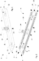
figure 1 is a top schematic axonometric view of a supporting device according to a first embodiment of the invention; -
figure 2 is a bottom schematic axonometric view of the supporting device according to the first embodiment of the invention; -
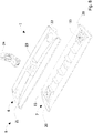
figure 3 is a schematic top exploded view of the supporting device according to the first embodiment of the invention; -
figure 4 is a schematic bottom exploded view of the supporting device according to the first embodiment of the invention; -
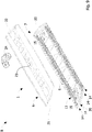
figure 5 is a schematic section taken along a transverse plane offigure 1 , of the supporting device according to the first embodiment of the invention; -
figure 6 is a top schematic axonometric view of a supporting device according to a second embodiment of the invention; -
figure 7 is a bottom schematic axonometric view of the supporting device according to the second embodiment of the invention; -
figure 8 is a schematic top exploded view of the supporting device according to the second embodiment of the invention; -
figure 9 schematic bottom exploded view of the supporting device according to the second embodiment of the invention; -
figure 10 is a schematic section taken along a transverse plane offigure 6 , of the supporting device according to the second embodiment of the invention; -
figure 11 is a schematic view of projecting elements included in the supporting device according to the invention; -
figure 12 is an enlarged schematic view of one of the projecting elements offigure 11 ; -
figure 13 is a schematic view of gripping means included in the supporting device according to the invention; and -
figure 14 is a schematic plan view of a cleaning element that is associable with the supporting device according to the invention. - With reference to
figures 1 to 5 , a supportingdevice 1 according to a first embodiment A of the invention is shown. - The supporting
device 1 is configured for removably supporting a cleaning element M, in particular for supporting a cleaning cloth, or "mop", illustrated schematically infigure 14 . - The supporting
device 1 has a substantially rectangular shape, extends along a longitudinal axis of prevalent extent, and comprises alower side 2, facing, in use, a surface to be cleaned, which is not shown, anupper side 3, opposite thelower side 2, a firstlateral side 4 and a secondlateral side 5, opposite one another and extend transversely to the longitudinal axis of prevalent extent of the supportingdevice 1, and a thirdlateral side 25 and a fourthlateral side 26, which are opposite one another and extend parallel to the longitudinal axis of prevalent extent of the supportingdevice 1. - Also, the supporting
device 1 is formed by abase body 6 and by asupport body 7, thesupport body 7 being overmoulded, for example by injection moulding, onto thebase body 6. - The
base body 6 is made of metal, in particular aluminium, whereas thesupport body 7 is made of plastics. - In an alternative embodiment of the first embodiment A, also the
base body 6 is made of plastics. - The supporting
device 1 further comprises holding means, for holding removably the cleaning element M that is anchored to the supportingdevice 1. - As is illustrated better in
figures 11 and 12 , the holding means comprises a plurality of hook-shaped projecting elements 9 that project from thelower side 2 of the supportingdevice 1, which projectingelements 9 are provided with afree end 10 configured for holding, removably, a substantially flat surface portion M1, of the cleaning element M. - In particular, each projecting
element 9 comprises astem 11, for example tapering away from thelower side 2 of the supportingdevice 1, and ahead 12, positioned at thefree end 10, which is a wider than an end of thestem 11 with which it is integral, so as to grasp wires projecting from the surface M1 of the cleaning element M. - Once the cleaning element M has been used it can be easily removed from the supporting
device 1 by exerting on the cleaning element M sufficient force to disengage theheads 12 from the wires of the cleaning element M, with a movement that is similar to a sharp pull. - Also, in order to improve the holding capacity of the projecting
elements 9, they are arranged equidistantly angularly to one another to form a plurality ofcircles 13. - In one embodiment of the invention, which is not shown, the projecting
elements 9 are arranged so as to form other geometric figures, for example squares, rectangles, polygons, ellipses, etc. - In turn, the
circles 13 are arranged inrows 14 that are parallel to one another and staggered with respect to the longitudinal axis of prevalent extent of the supportingdevice 1. - The holding means further comprises a pair of gripping means 15, which is illustrated in greater detail in
figure 13 , arranged at and on opposite sides of theupper side 3 of the supportingdevice 1, which gripping means 15 is configured for holding, removably, possible free edges M2, M3 (figure 14 ) of the cleaning element M. - In particular, each of the gripping means 15 comprises a plurality of
flexible gripping elements 16, that are separated from one another bycutting lines 17. - More precisely, the
gripping elements 16, which are for example eight in number, have a triangular shape, are connected together along an edge P, for example of elliptic shape, and are provided withfree vertices 18 that are spaced apart from one another so as to define an outline of athrough hole 19. - In use, a pair of free edges M2, M3 of the cleaning element M is inserted into the through
hole 19 of each of the gripping means 15, this flexing to the inside of the supportingdevice 1 one or more of thegripping elements 16, so as to hold therebetween the free edges M2, M3. - The supporting
device 1 further comprises bumper means 20, having, for example, a curvilinear profile, arranged for protecting the supportingdevice 1, in particular thebase body 6, from lateral impacts. - In order to do this, the bumper means 20 is positioned at
opposite ends base body 6, thereby defining thelateral sides device 1. - Lastly, the supporting
device 1 comprises fixing means 23, for fixing ahandle 24 to the supportingdevice 1, to enable an operator to operate the supportingdevice 1. - The assembly formed by the supporting
device 1, by the cleaning element M, and by thehandle 24, makes a so-called "broom mop". - According to the first embodiment A, the holding means 9, 15, the bumper means 20 and the fixing means 23 are parts of the
support body 7, i.e. are formed as a single body, thesupport body 7 being made by injection moulding and being overmoulded, as said above, onto thebase body 6. - In other words, in the first embodiment A the
support body 7 is formed by the holding means 9, 15, by the bumper means 20 and by thefixing means 23. - With reference to
figures 6 to 10 , a supportingdevice 1 according to a second embodiment B of the invention is shown. - The supporting
device 1 according to the second embodiment B differs from the supportingdevice 1 according to the first embodiment A in that thebase body 6 is made of plastics, just like thesupport body 7, and in that the fixing means 23 forms a single body with thebase body 6; the holding means 9, 15 and the bumper means 20 forming a single body with thesupport body 7. - It should be noted how the method for making the supporting
device 1 is particularly simple, rapid and cheap. - It is in fact sufficient to overmould, for example by injection moulding, the
support body 7 onto thebase body 6 without the need for any manual fitting. - It should be noted further how the supporting
device 1 according to the invention is particularly efficient. - It is in fact possible to make the
base body 6 and thesupport body 7 with different plastics so as to improve the efficiency of the supportingdevice 1, i.e. the capacity of the bumper means 20 to absorb the impacts, the capacity of theholding means handle 24 firmly. - The invention that is thus conceived is capable of undergoing numerous modifications and variations that all fall within the scope of the inventive concept. Further, all the details can be replaced by technically equivalent elements.
Claims (16)
- Supporting device (1) configured for removably supporting a cleaning element (M), in particular a cleaning cloth, comprising:an elongated base body (6);holding means (9; 15), for removably holding said cleaning element (M); andbumper means (20), arranged at opposite ends of said supporting device (1), for protecting said supporting device (1) from lateral impacts;said supporting device (1) is characterised in thatsaid holding means (9; 15) and said bumper means (20) are parts of a support body (7) fixed to said base body (6) by overmoulding.
- Supporting device (1) according to claim 1, and comprising fixing means (23), for fixing a handle (24) to said supporting device (1).
- Supporting device (1) according to claim 1, or 2, wherein said fixing means (23) is part of said support body (7).
- Supporting device (1) according to any one of claims 1 to 3, wherein said support body (7) is formed as a single body.
- Supporting device (1) according to claim 2, wherein said fixing means (23) is part of said base body (6).
- Supporting device (1) according to claim 5, wherein said base body (6) is a single body.
- Supporting device (1) according to any one of claims 1 to 6, wherein said base body (6) is made of a metal material, or of plastics, and wherein said support body (7) is made of plastics.
- Supporting device (1) according to any one of claims 1 to 7, wherein said holding means (9; 15) comprises a plurality of projecting elements (9) projecting from a lower side (2) of said supporting device (1), which projecting elements (9) are provided with a free end (10) configured for removably holding said cleaning element (M).
- Supporting device (1) according to claim 8, wherein said projecting elements (9) are arranged, spaced angularly equidistantly from one another, to form a plurality of geometric figures, in particular circles (13).
- Supporting device (1) according to any one of claims 1 to 9, wherein said holding means (9; 15) comprises a pair of gripping means (15) arranged on opposite sides of an upper side (3) of said supporting device (1), which gripping means (15) is configured for holding possible free edges (M2, M3) of said cleaning element (M).
- Supporting device (1) according to claim 10, wherein each of said gripping means (15) comprises a plurality of flexible gripping elements (16) which are separated from one another by cutting lines (17).
- Supporting device (1) according to claim 11, wherein said gripping elements (16) have a triangular shape, the free vertices (18) of said gripping elements (16) defining an outline of a through hole (19).
- Method for making a supporting device (1) configured for removably supporting a cleaning element (M), in particular a cleaning cloth, comprising the steps of:forming an elongated base body (6);forming holding means (9; 15), for removably holding said cleaning element (M); andforming bumper means (20), arranged at opposite ends of said supporting device (1), for protecting said supporting device (1) from lateral impacts;said method is characterised in that it comprises the step offorming as a single body said holding means (9; 15) and said bumper means (20) so as to make a support body (7) which is fixable to said base body (6) by overmoulding.
- Method according to claim 13, and comprising the step of forming fixing means (23), for fixing a handle (24) to said base body (6).
- Method according to claim 14, wherein said forming as a single body comprises forming as a single body said holding means (9; 15), said bumper means (20) and said fixing means (23) so as to make said support body (7).
- Method according to claim 14, wherein forming said base body (6) comprises forming as a single body said fixing means (23) and said base body (6).
Applications Claiming Priority (1)
| Application Number | Priority Date | Filing Date | Title |
|---|---|---|---|
| IT102017000054839A IT201700054839A1 (en) | 2017-05-19 | 2017-05-19 | Support device and method for making such a support device |
Publications (2)
| Publication Number | Publication Date |
|---|---|
| EP3403563A1 true EP3403563A1 (en) | 2018-11-21 |
| EP3403563B1 EP3403563B1 (en) | 2020-04-22 |
Family
ID=59974789
Family Applications (1)
| Application Number | Title | Priority Date | Filing Date |
|---|---|---|---|
| EP18173323.9A Active EP3403563B1 (en) | 2017-05-19 | 2018-05-18 | Supporting device and method for making such a supporting device |
Country Status (3)
| Country | Link |
|---|---|
| EP (1) | EP3403563B1 (en) |
| ES (1) | ES2807030T3 (en) |
| IT (1) | IT201700054839A1 (en) |
Citations (4)
| Publication number | Priority date | Publication date | Assignee | Title |
|---|---|---|---|---|
| US20060230567A1 (en) * | 2005-04-13 | 2006-10-19 | The Procter & Gamble Company | Cleaning implement |
| US8425137B1 (en) * | 2012-02-10 | 2013-04-23 | Casabella Holdings, Llc | Double sided spray mop |
| WO2015132471A1 (en) * | 2014-03-05 | 2015-09-11 | Sinituote Oy | A mop body and method for preparation thereof |
| US20160256030A1 (en) * | 2015-03-06 | 2016-09-08 | The Libman Company | Cleaning Implement with Resilient Projections |
-
2017
- 2017-05-19 IT IT102017000054839A patent/IT201700054839A1/en unknown
-
2018
- 2018-05-18 ES ES18173323T patent/ES2807030T3/en active Active
- 2018-05-18 EP EP18173323.9A patent/EP3403563B1/en active Active
Patent Citations (4)
| Publication number | Priority date | Publication date | Assignee | Title |
|---|---|---|---|---|
| US20060230567A1 (en) * | 2005-04-13 | 2006-10-19 | The Procter & Gamble Company | Cleaning implement |
| US8425137B1 (en) * | 2012-02-10 | 2013-04-23 | Casabella Holdings, Llc | Double sided spray mop |
| WO2015132471A1 (en) * | 2014-03-05 | 2015-09-11 | Sinituote Oy | A mop body and method for preparation thereof |
| US20160256030A1 (en) * | 2015-03-06 | 2016-09-08 | The Libman Company | Cleaning Implement with Resilient Projections |
Also Published As
| Publication number | Publication date |
|---|---|
| EP3403563B1 (en) | 2020-04-22 |
| ES2807030T3 (en) | 2021-02-19 |
| IT201700054839A1 (en) | 2018-11-19 |
Similar Documents
| Publication | Publication Date | Title |
|---|---|---|
| US10881197B2 (en) | Grill-cleaning tool | |
| US3275187A (en) | Painter's utility implement | |
| US20140238310A1 (en) | Pet deshedding tool | |
| US20100269278A1 (en) | Interdental Brush | |
| US8832898B1 (en) | Two-handed scraping device | |
| US9408459B2 (en) | Combination broom and shovel | |
| US20110239392A1 (en) | Brush with a variable edge | |
| US20120279520A1 (en) | Push broom apparatus | |
| US2727268A (en) | Handled washing mops | |
| RU2014129027A (en) | FORMING ELEMENT CONTAINING CUTTING PRODUCT FOR FORMING AND VOLCANIZING TIRES | |
| US8533896B2 (en) | Method and apparatus for removing ice and snow deposits from a vehicle | |
| EP3403563B1 (en) | Supporting device and method for making such a supporting device | |
| US20170188696A1 (en) | Surface Cleaning Brush | |
| IL284754B (en) | A broom with a fine dust sweeping element | |
| US5922139A (en) | Rake for cleaning the teeth of carpet stretchers | |
| US8918949B2 (en) | Paint distributing plate system | |
| EP3094229B1 (en) | Cleaning tool | |
| US20180327988A1 (en) | Double-Handle Snow Shovel | |
| TW201622613A (en) | Car snow brush and manufacturing method | |
| US20220203570A1 (en) | Bristle brush | |
| US7077914B2 (en) | Rigid paint scraper with flexible bends | |
| JP2019000333A5 (en) | ||
| US5461783A (en) | New style trim knife | |
| AU2020100131A4 (en) | A cleaning tool | |
| EP3331785A1 (en) | Base for conveyor belt scraper |
Legal Events
| Date | Code | Title | Description |
|---|---|---|---|
| PUAI | Public reference made under article 153(3) epc to a published international application that has entered the european phase |
Free format text: ORIGINAL CODE: 0009012 |
|
| STAA | Information on the status of an ep patent application or granted ep patent |
Free format text: STATUS: THE APPLICATION HAS BEEN PUBLISHED |
|
| AK | Designated contracting states |
Kind code of ref document: A1 Designated state(s): AL AT BE BG CH CY CZ DE DK EE ES FI FR GB GR HR HU IE IS IT LI LT LU LV MC MK MT NL NO PL PT RO RS SE SI SK SM TR |
|
| AX | Request for extension of the european patent |
Extension state: BA ME |
|
| STAA | Information on the status of an ep patent application or granted ep patent |
Free format text: STATUS: REQUEST FOR EXAMINATION WAS MADE |
|
| 17P | Request for examination filed |
Effective date: 20190521 |
|
| RBV | Designated contracting states (corrected) |
Designated state(s): AL AT BE BG CH CY CZ DE DK EE ES FI FR GB GR HR HU IE IS IT LI LT LU LV MC MK MT NL NO PL PT RO RS SE SI SK SM TR |
|
| GRAP | Despatch of communication of intention to grant a patent |
Free format text: ORIGINAL CODE: EPIDOSNIGR1 |
|
| STAA | Information on the status of an ep patent application or granted ep patent |
Free format text: STATUS: GRANT OF PATENT IS INTENDED |
|
| INTG | Intention to grant announced |
Effective date: 20191115 |
|
| GRAS | Grant fee paid |
Free format text: ORIGINAL CODE: EPIDOSNIGR3 |
|
| GRAA | (expected) grant |
Free format text: ORIGINAL CODE: 0009210 |
|
| STAA | Information on the status of an ep patent application or granted ep patent |
Free format text: STATUS: THE PATENT HAS BEEN GRANTED |
|
| AK | Designated contracting states |
Kind code of ref document: B1 Designated state(s): AL AT BE BG CH CY CZ DE DK EE ES FI FR GB GR HR HU IE IS IT LI LT LU LV MC MK MT NL NO PL PT RO RS SE SI SK SM TR |
|
| REG | Reference to a national code |
Ref country code: CH Ref legal event code: EP |
|
| REG | Reference to a national code |
Ref country code: IE Ref legal event code: FG4D |
|
| REG | Reference to a national code |
Ref country code: DE Ref legal event code: R096 Ref document number: 602018003908 Country of ref document: DE |
|
| REG | Reference to a national code |
Ref country code: AT Ref legal event code: REF Ref document number: 1258959 Country of ref document: AT Kind code of ref document: T Effective date: 20200515 |
|
| REG | Reference to a national code |
Ref country code: LT Ref legal event code: MG4D |
|
| REG | Reference to a national code |
Ref country code: NL Ref legal event code: MP Effective date: 20200422 |
|
| PG25 | Lapsed in a contracting state [announced via postgrant information from national office to epo] |
Ref country code: FI Free format text: LAPSE BECAUSE OF FAILURE TO SUBMIT A TRANSLATION OF THE DESCRIPTION OR TO PAY THE FEE WITHIN THE PRESCRIBED TIME-LIMIT Effective date: 20200422 Ref country code: IS Free format text: LAPSE BECAUSE OF FAILURE TO SUBMIT A TRANSLATION OF THE DESCRIPTION OR TO PAY THE FEE WITHIN THE PRESCRIBED TIME-LIMIT Effective date: 20200822 Ref country code: GR Free format text: LAPSE BECAUSE OF FAILURE TO SUBMIT A TRANSLATION OF THE DESCRIPTION OR TO PAY THE FEE WITHIN THE PRESCRIBED TIME-LIMIT Effective date: 20200723 Ref country code: NO Free format text: LAPSE BECAUSE OF FAILURE TO SUBMIT A TRANSLATION OF THE DESCRIPTION OR TO PAY THE FEE WITHIN THE PRESCRIBED TIME-LIMIT Effective date: 20200722 Ref country code: NL Free format text: LAPSE BECAUSE OF FAILURE TO SUBMIT A TRANSLATION OF THE DESCRIPTION OR TO PAY THE FEE WITHIN THE PRESCRIBED TIME-LIMIT Effective date: 20200422 Ref country code: SE Free format text: LAPSE BECAUSE OF FAILURE TO SUBMIT A TRANSLATION OF THE DESCRIPTION OR TO PAY THE FEE WITHIN THE PRESCRIBED TIME-LIMIT Effective date: 20200422 Ref country code: PT Free format text: LAPSE BECAUSE OF FAILURE TO SUBMIT A TRANSLATION OF THE DESCRIPTION OR TO PAY THE FEE WITHIN THE PRESCRIBED TIME-LIMIT Effective date: 20200824 Ref country code: LT Free format text: LAPSE BECAUSE OF FAILURE TO SUBMIT A TRANSLATION OF THE DESCRIPTION OR TO PAY THE FEE WITHIN THE PRESCRIBED TIME-LIMIT Effective date: 20200422 |
|
| REG | Reference to a national code |
Ref country code: AT Ref legal event code: MK05 Ref document number: 1258959 Country of ref document: AT Kind code of ref document: T Effective date: 20200422 |
|
| PG25 | Lapsed in a contracting state [announced via postgrant information from national office to epo] |
Ref country code: RS Free format text: LAPSE BECAUSE OF FAILURE TO SUBMIT A TRANSLATION OF THE DESCRIPTION OR TO PAY THE FEE WITHIN THE PRESCRIBED TIME-LIMIT Effective date: 20200422 Ref country code: BG Free format text: LAPSE BECAUSE OF FAILURE TO SUBMIT A TRANSLATION OF THE DESCRIPTION OR TO PAY THE FEE WITHIN THE PRESCRIBED TIME-LIMIT Effective date: 20200722 Ref country code: LV Free format text: LAPSE BECAUSE OF FAILURE TO SUBMIT A TRANSLATION OF THE DESCRIPTION OR TO PAY THE FEE WITHIN THE PRESCRIBED TIME-LIMIT Effective date: 20200422 Ref country code: HR Free format text: LAPSE BECAUSE OF FAILURE TO SUBMIT A TRANSLATION OF THE DESCRIPTION OR TO PAY THE FEE WITHIN THE PRESCRIBED TIME-LIMIT Effective date: 20200422 |
|
| REG | Reference to a national code |
Ref country code: DE Ref legal event code: R119 Ref document number: 602018003908 Country of ref document: DE |
|
| PG25 | Lapsed in a contracting state [announced via postgrant information from national office to epo] |
Ref country code: AL Free format text: LAPSE BECAUSE OF FAILURE TO SUBMIT A TRANSLATION OF THE DESCRIPTION OR TO PAY THE FEE WITHIN THE PRESCRIBED TIME-LIMIT Effective date: 20200422 |
|
| PG25 | Lapsed in a contracting state [announced via postgrant information from national office to epo] |
Ref country code: MC Free format text: LAPSE BECAUSE OF FAILURE TO SUBMIT A TRANSLATION OF THE DESCRIPTION OR TO PAY THE FEE WITHIN THE PRESCRIBED TIME-LIMIT Effective date: 20200422 Ref country code: EE Free format text: LAPSE BECAUSE OF FAILURE TO SUBMIT A TRANSLATION OF THE DESCRIPTION OR TO PAY THE FEE WITHIN THE PRESCRIBED TIME-LIMIT Effective date: 20200422 Ref country code: DK Free format text: LAPSE BECAUSE OF FAILURE TO SUBMIT A TRANSLATION OF THE DESCRIPTION OR TO PAY THE FEE WITHIN THE PRESCRIBED TIME-LIMIT Effective date: 20200422 Ref country code: AT Free format text: LAPSE BECAUSE OF FAILURE TO SUBMIT A TRANSLATION OF THE DESCRIPTION OR TO PAY THE FEE WITHIN THE PRESCRIBED TIME-LIMIT Effective date: 20200422 Ref country code: SM Free format text: LAPSE BECAUSE OF FAILURE TO SUBMIT A TRANSLATION OF THE DESCRIPTION OR TO PAY THE FEE WITHIN THE PRESCRIBED TIME-LIMIT Effective date: 20200422 Ref country code: CZ Free format text: LAPSE BECAUSE OF FAILURE TO SUBMIT A TRANSLATION OF THE DESCRIPTION OR TO PAY THE FEE WITHIN THE PRESCRIBED TIME-LIMIT Effective date: 20200422 Ref country code: RO Free format text: LAPSE BECAUSE OF FAILURE TO SUBMIT A TRANSLATION OF THE DESCRIPTION OR TO PAY THE FEE WITHIN THE PRESCRIBED TIME-LIMIT Effective date: 20200422 |
|
| REG | Reference to a national code |
Ref country code: ES Ref legal event code: FG2A Ref document number: 2807030 Country of ref document: ES Kind code of ref document: T3 Effective date: 20210219 |
|
| PG25 | Lapsed in a contracting state [announced via postgrant information from national office to epo] |
Ref country code: PL Free format text: LAPSE BECAUSE OF FAILURE TO SUBMIT A TRANSLATION OF THE DESCRIPTION OR TO PAY THE FEE WITHIN THE PRESCRIBED TIME-LIMIT Effective date: 20200422 Ref country code: SK Free format text: LAPSE BECAUSE OF FAILURE TO SUBMIT A TRANSLATION OF THE DESCRIPTION OR TO PAY THE FEE WITHIN THE PRESCRIBED TIME-LIMIT Effective date: 20200422 |
|
| PLBE | No opposition filed within time limit |
Free format text: ORIGINAL CODE: 0009261 |
|
| STAA | Information on the status of an ep patent application or granted ep patent |
Free format text: STATUS: NO OPPOSITION FILED WITHIN TIME LIMIT |
|
| REG | Reference to a national code |
Ref country code: BE Ref legal event code: MM Effective date: 20200531 |
|
| 26N | No opposition filed |
Effective date: 20210125 |
|
| PG25 | Lapsed in a contracting state [announced via postgrant information from national office to epo] |
Ref country code: LU Free format text: LAPSE BECAUSE OF NON-PAYMENT OF DUE FEES Effective date: 20200518 |
|
| PG25 | Lapsed in a contracting state [announced via postgrant information from national office to epo] |
Ref country code: IE Free format text: LAPSE BECAUSE OF NON-PAYMENT OF DUE FEES Effective date: 20200518 |
|
| PG25 | Lapsed in a contracting state [announced via postgrant information from national office to epo] |
Ref country code: BE Free format text: LAPSE BECAUSE OF NON-PAYMENT OF DUE FEES Effective date: 20200531 Ref country code: DE Free format text: LAPSE BECAUSE OF NON-PAYMENT OF DUE FEES Effective date: 20201201 Ref country code: SI Free format text: LAPSE BECAUSE OF FAILURE TO SUBMIT A TRANSLATION OF THE DESCRIPTION OR TO PAY THE FEE WITHIN THE PRESCRIBED TIME-LIMIT Effective date: 20200422 |
|
| REG | Reference to a national code |
Ref country code: CH Ref legal event code: PL |
|
| PG25 | Lapsed in a contracting state [announced via postgrant information from national office to epo] |
Ref country code: LI Free format text: LAPSE BECAUSE OF NON-PAYMENT OF DUE FEES Effective date: 20210531 Ref country code: CH Free format text: LAPSE BECAUSE OF NON-PAYMENT OF DUE FEES Effective date: 20210531 |
|
| PG25 | Lapsed in a contracting state [announced via postgrant information from national office to epo] |
Ref country code: TR Free format text: LAPSE BECAUSE OF FAILURE TO SUBMIT A TRANSLATION OF THE DESCRIPTION OR TO PAY THE FEE WITHIN THE PRESCRIBED TIME-LIMIT Effective date: 20200422 Ref country code: MT Free format text: LAPSE BECAUSE OF FAILURE TO SUBMIT A TRANSLATION OF THE DESCRIPTION OR TO PAY THE FEE WITHIN THE PRESCRIBED TIME-LIMIT Effective date: 20200422 Ref country code: CY Free format text: LAPSE BECAUSE OF FAILURE TO SUBMIT A TRANSLATION OF THE DESCRIPTION OR TO PAY THE FEE WITHIN THE PRESCRIBED TIME-LIMIT Effective date: 20200422 |
|
| PG25 | Lapsed in a contracting state [announced via postgrant information from national office to epo] |
Ref country code: MK Free format text: LAPSE BECAUSE OF FAILURE TO SUBMIT A TRANSLATION OF THE DESCRIPTION OR TO PAY THE FEE WITHIN THE PRESCRIBED TIME-LIMIT Effective date: 20200422 |
|
| PGFP | Annual fee paid to national office [announced via postgrant information from national office to epo] |
Ref country code: ES Payment date: 20260601 Year of fee payment: 9 |
|
| PGFP | Annual fee paid to national office [announced via postgrant information from national office to epo] |
Ref country code: GB Payment date: 20260527 Year of fee payment: 9 |
|
| PGFP | Annual fee paid to national office [announced via postgrant information from national office to epo] |
Ref country code: IT Payment date: 20260527 Year of fee payment: 9 |
|
| PGFP | Annual fee paid to national office [announced via postgrant information from national office to epo] |
Ref country code: FR Payment date: 20260525 Year of fee payment: 9 |