EP3403532B1 - Rack system having electrical supply - Google Patents
Rack system having electrical supply Download PDFInfo
- Publication number
- EP3403532B1 EP3403532B1 EP17175978.0A EP17175978A EP3403532B1 EP 3403532 B1 EP3403532 B1 EP 3403532B1 EP 17175978 A EP17175978 A EP 17175978A EP 3403532 B1 EP3403532 B1 EP 3403532B1
- Authority
- EP
- European Patent Office
- Prior art keywords
- rack system
- electrical supply
- magnetic
- bus bar
- receiving grooves
- Prior art date
- Legal status (The legal status is an assumption and is not a legal conclusion. Google has not performed a legal analysis and makes no representation as to the accuracy of the status listed.)
- Active
Links
Images

Classifications
-
- A—HUMAN NECESSITIES
- A47—FURNITURE; DOMESTIC ARTICLES OR APPLIANCES; COFFEE MILLS; SPICE MILLS; SUCTION CLEANERS IN GENERAL
- A47B—TABLES; DESKS; OFFICE FURNITURE; CABINETS; DRAWERS; GENERAL DETAILS OF FURNITURE
- A47B97/00—Furniture or accessories for furniture, not provided for in other groups of this subclass
-
- H—ELECTRICITY
- H01—ELECTRIC ELEMENTS
- H01R—ELECTRICALLY-CONDUCTIVE CONNECTIONS; STRUCTURAL ASSOCIATIONS OF A PLURALITY OF MUTUALLY-INSULATED ELECTRICAL CONNECTING ELEMENTS; COUPLING DEVICES; CURRENT COLLECTORS
- H01R25/00—Coupling parts adapted for simultaneous co-operation with two or more identical counterparts, e.g. for distributing energy to two or more circuits
- H01R25/14—Rails or bus-bars constructed so that the counterparts can be connected thereto at any point along their length
-
- A—HUMAN NECESSITIES
- A47—FURNITURE; DOMESTIC ARTICLES OR APPLIANCES; COFFEE MILLS; SPICE MILLS; SUCTION CLEANERS IN GENERAL
- A47F—SPECIAL FURNITURE, FITTINGS, OR ACCESSORIES FOR SHOPS, STOREHOUSES, BARS, RESTAURANTS OR THE LIKE; PAYING COUNTERS
- A47F5/00—Show stands, hangers, or shelves characterised by their constructional features
- A47F5/0043—Show shelves
-
- A—HUMAN NECESSITIES
- A47—FURNITURE; DOMESTIC ARTICLES OR APPLIANCES; COFFEE MILLS; SPICE MILLS; SUCTION CLEANERS IN GENERAL
- A47F—SPECIAL FURNITURE, FITTINGS, OR ACCESSORIES FOR SHOPS, STOREHOUSES, BARS, RESTAURANTS OR THE LIKE; PAYING COUNTERS
- A47F11/00—Arrangements in shop windows, shop floors or show cases
- A47F11/06—Means for bringing about special optical effects
- A47F11/10—Arrangements of light sources
-
- F—MECHANICAL ENGINEERING; LIGHTING; HEATING; WEAPONS; BLASTING
- F21—LIGHTING
- F21V—FUNCTIONAL FEATURES OR DETAILS OF LIGHTING DEVICES OR SYSTEMS THEREOF; STRUCTURAL COMBINATIONS OF LIGHTING DEVICES WITH OTHER ARTICLES, NOT OTHERWISE PROVIDED FOR
- F21V21/00—Supporting, suspending, or attaching arrangements for lighting devices; Hand grips
- F21V21/34—Supporting elements displaceable along a guiding element
- F21V21/35—Supporting elements displaceable along a guiding element with direct electrical contact between the supporting element and electric conductors running along the guiding element
-
- H—ELECTRICITY
- H01—ELECTRIC ELEMENTS
- H01R—ELECTRICALLY-CONDUCTIVE CONNECTIONS; STRUCTURAL ASSOCIATIONS OF A PLURALITY OF MUTUALLY-INSULATED ELECTRICAL CONNECTING ELEMENTS; COUPLING DEVICES; CURRENT COLLECTORS
- H01R13/00—Details of coupling devices of the kinds covered by groups H01R12/70 or H01R24/00 - H01R33/00
- H01R13/02—Contact members
- H01R13/22—Contacts for co-operating by abutting
- H01R13/24—Contacts for co-operating by abutting resilient; resiliently-mounted
-
- H—ELECTRICITY
- H01—ELECTRIC ELEMENTS
- H01R—ELECTRICALLY-CONDUCTIVE CONNECTIONS; STRUCTURAL ASSOCIATIONS OF A PLURALITY OF MUTUALLY-INSULATED ELECTRICAL CONNECTING ELEMENTS; COUPLING DEVICES; CURRENT COLLECTORS
- H01R13/00—Details of coupling devices of the kinds covered by groups H01R12/70 or H01R24/00 - H01R33/00
- H01R13/62—Means for facilitating engagement or disengagement of coupling parts or for holding them in engagement
- H01R13/6205—Two-part coupling devices held in engagement by a magnet
-
- H—ELECTRICITY
- H01—ELECTRIC ELEMENTS
- H01R—ELECTRICALLY-CONDUCTIVE CONNECTIONS; STRUCTURAL ASSOCIATIONS OF A PLURALITY OF MUTUALLY-INSULATED ELECTRICAL CONNECTING ELEMENTS; COUPLING DEVICES; CURRENT COLLECTORS
- H01R13/00—Details of coupling devices of the kinds covered by groups H01R12/70 or H01R24/00 - H01R33/00
- H01R13/73—Means for mounting coupling parts to apparatus or structures, e.g. to a wall
-
- H—ELECTRICITY
- H01—ELECTRIC ELEMENTS
- H01R—ELECTRICALLY-CONDUCTIVE CONNECTIONS; STRUCTURAL ASSOCIATIONS OF A PLURALITY OF MUTUALLY-INSULATED ELECTRICAL CONNECTING ELEMENTS; COUPLING DEVICES; CURRENT COLLECTORS
- H01R25/00—Coupling parts adapted for simultaneous co-operation with two or more identical counterparts, e.g. for distributing energy to two or more circuits
- H01R25/14—Rails or bus-bars constructed so that the counterparts can be connected thereto at any point along their length
- H01R25/142—Their counterparts
-
- A—HUMAN NECESSITIES
- A47—FURNITURE; DOMESTIC ARTICLES OR APPLIANCES; COFFEE MILLS; SPICE MILLS; SUCTION CLEANERS IN GENERAL
- A47B—TABLES; DESKS; OFFICE FURNITURE; CABINETS; DRAWERS; GENERAL DETAILS OF FURNITURE
- A47B2220/00—General furniture construction, e.g. fittings
- A47B2220/0075—Lighting
- A47B2220/0077—Lighting for furniture, e.g. cupboards and racks
-
- A—HUMAN NECESSITIES
- A47—FURNITURE; DOMESTIC ARTICLES OR APPLIANCES; COFFEE MILLS; SPICE MILLS; SUCTION CLEANERS IN GENERAL
- A47F—SPECIAL FURNITURE, FITTINGS, OR ACCESSORIES FOR SHOPS, STOREHOUSES, BARS, RESTAURANTS OR THE LIKE; PAYING COUNTERS
- A47F5/00—Show stands, hangers, or shelves characterised by their constructional features
- A47F5/0081—Show stands or display racks with movable parts
-
- F—MECHANICAL ENGINEERING; LIGHTING; HEATING; WEAPONS; BLASTING
- F21—LIGHTING
- F21W—INDEXING SCHEME ASSOCIATED WITH SUBCLASSES F21K, F21L, F21S and F21V, RELATING TO USES OR APPLICATIONS OF LIGHTING DEVICES OR SYSTEMS
- F21W2131/00—Use or application of lighting devices or systems not provided for in codes F21W2102/00-F21W2121/00
- F21W2131/30—Lighting for domestic or personal use
- F21W2131/301—Lighting for domestic or personal use for furniture
Definitions
- the present application relates to a shelving equipments, and more particularly to a rack system having an electrical supply.
- the rack system is widely used, such as in shopping malls, logistics warehouses, factory warehouses, and so on, and is provided to place some goods or display some items.
- the lighting is necessary in the rack system, especially in the use of the shelve in the store, the lighting requirements are particularly high, such as saving space, security, easy assembly, beauty, and so on.
- the wires of the electrical supply of the rack system generally first pass through the hollow shelve rail of the rack system, and extend out from the shelve rail, and then, they are arranged along carrier elements to supply electric for the lighting.
- the entire rack system has been assembled and placed in the mall or supermarket, if you want to set the electrical supply, it will be very troublesome as it is difficult to disassemble the entire shelf and need to arrange the wires. As a result, it costs plurality of manpower hours.
- a shelf power distribution apparatus comprising a track element that further comprises: a first electrical conductor and a first magnet, wherein the first magnet facilitates the attachment of the track element to a shelf; a first cover element that further comprises a second magnet; and wherein the second magnet facilitates the attachment of the cover to the track element.
- the rack system having the electrical supply 100 includes at least one backboard 10, a bus bar 20 mounted on the backboard 10, and at least one supplier 30 arranged on the bus bar 20.
- the rack system having the electrical supply 100 may include other modules, such as shelves rails, carrier elements, angle brackets, and so on, and wires electrically connecting the bus bar 20 with main powers, and wires electrically connecting the supplier 30 to the lightings. These modules are well known by a person skilled in the art, and no need to explain in detail.
- the backboard 10 may be typically a flat plate and made of metal material, such as steel, and is inserted into the shelves rails for isolating different shelf spaces.
- the backboard 10 has a same configuration with that in the existing supermarket or the shopping mall. Therefore, it is no need to describe in detail.
- the bus bar 20 includes a track body 21, two magnetic strips 22 provided on the track body 21, and two current conductors 23 spaced apart from each other and disposed on the trace body 21.
- the track body 21 is made of insulating material, such as plastic.
- the track body 21 may be arranged along the vertical direction of the shelves rails so that the lamps provided on a plurality of the carrier elements can be powered.
- the track body 21 includes two magnetic strip receiving grooves 211 spaced apart from each other, and two conductor receiving grooves 212 spaced apart from each other and disposed between the two magnetic strip receiving grooves 211.
- a width and a depth of the magnetic strip receiving grooves 211 are equal to a width and a thickness of the magnetic strip 22.
- Each of the two conductor receiving grooves 212 includes two L-shaped side walls so that one of the two current conductors 23 can be inserted into the two L-shaded side walls therebetween.
- the magnetic strips 22 may be made of soft magnetic material so as to be suitably deformed during installation.
- the magnetic strips 22 are attached to the magnetic strip receiving groove 211 via a method of adhering by glue, and so on.
- the bus bar 20 can be directly attracted onto the backboard 10 by the magnetic strips 22, and so, the installation of the bus bar 20 can be completed.
- the two current conductors 23 are inserted in the two conductor receiving grooves 212 respectively and are engaged with the current conductors 23 by the L-shaped side walls of the conductor receiving grooves 212 so as to fix the current conductors 23 therein.
- the center lines of the magnetic strips 22 overlap that of the current conductors 23 along the arrangement direction thereof so as to reduce the whole thickness of the bus bar 20.
- the magnetic strip receiving grooves 211 and the conductor receiving grooves 212 are arranged on two opposite side walls of the track body 21, respectively
- the supplier 30 includes a main body 31, two holding portions 32 extending from the main body 31, two resilient contactors 33 disposed in the main body 31 and spaced apart from each other, a circuit board 34 mounted in the main body 31, a cover 35 arranged on the circuit board 34, two magnetic columns 36 disposed in the main body 31 and arranged on both sides of the two resilient contactors 33.
- the main body 31 is provided with two blind holes 311 for receiving the two magnetic columns 36 respectively and a receiving chamber 312 disposed between the two blind holes 311.
- the main body 31 may be injected from a plastic material and is integrally formed with the blind holes 311 and the receiving chamber 312.
- the receiving chamber 312 is configured for disposing the circuit board 34 and the two resilient contactors 33.
- the two holding portions 32 may also be molded together with the main body 31 and extend towards the bus bar 30 and engage with the two side walls of the bus bar 20 which are perpendicular to the arrangement direction of the magnetic strips 22 and the current conductors 23. Therefore, the supplier 30 can be moved along the extending direction of the bus bar 20.
- the resilient contactors 33 are prior art known to those skilled in the art and will be briefly described herein.
- the resilient contactor 33 includes a sleeve, a spring disposed in the sleeve, and a circular or stepped contactor extending beyond one end of the sleeve. The contactor can be secured in the sleeve by compressing the sleeve port to form the resilient contactor 33.
- the circuit board 34 is prior art known to those skilled in the art and is configured for electrically connecting various electronic components, such as triodes, diodes, resistors, and the like.
- the resilient contactors 33 may be fixed onto the circuit board 34 and electrically connected to the outer wires.
- the method of fixing the resilient contactors 33 may be a soldering.
- the cover 35 is arranged onto the circuit board 34 to protect the circuit board 34. It will be appreciated that the cover 35 is provided with two through holes therein for the resilient contactors 33.
- the magnetic columns 36 may be fixed in the two blind holes 311 respectively by interference fit.
- the bus bar 20 is firstly attached to the appropriated position of the backboard 10 by the magnetic strips 22, and the supplier 30 is arranged onto the bus bar 20.
- the two magnetic columns 36 are attached onto the two magnetic strips 22 respectively, and the two resilient contactors 33 are respectively abutted against the two magnetic strips 22 when the supplier 30 is mounted on the bus bar 20 so that the two resilient contactors 33 are electrically connected to the current conductors 33, respectively.
- the resilient contactors 33 when the resilient contactors 33 are electrically connected to the current conductors 23, the resilient contactor 33 will pass through the gap formed between the two L-shaped side walls of the conductor receiving grooves 212.
- the rack system having the electrical supply 100 provided by the present invention can make the bus bar 20 thinner by using the structure thereof, for example, a thickness of 2 mm to 3 mm. Therefore, the bus bar 20 can directly pass from the tolerance gap between the backboard 10 and the carrier elements without disassembling the whole rack system, thereby completing the installation of the bus bar 20. And then, the supplier 30 can be directly placed onto the bus bar 20 so as to achieve electrically connection. As a result, it is easy to install the rack system having the electrical supply so as to save cost and time.
Landscapes
- Engineering & Computer Science (AREA)
- General Engineering & Computer Science (AREA)
- Warehouses Or Storage Devices (AREA)
- Supply And Installment Of Electrical Components (AREA)
Description
- This present application claims benefit of the Chinese Application,
CN201710345195.7, filed on May 16, 2017 - The present application relates to a shelving equipments, and more particularly to a rack system having an electrical supply.
- The rack system is widely used, such as in shopping malls, logistics warehouses, factory warehouses, and so on, and is provided to place some goods or display some items. The lighting is necessary in the rack system, especially in the use of the shelve in the store, the lighting requirements are particularly high, such as saving space, security, easy assembly, beauty, and so on.
- In the prior art, the wires of the electrical supply of the rack system generally first pass through the hollow shelve rail of the rack system, and extend out from the shelve rail, and then, they are arranged along carrier elements to supply electric for the lighting. However, when the entire rack system has been assembled and placed in the mall or supermarket, if you want to set the electrical supply, it will be very troublesome as it is difficult to disassemble the entire shelf and need to arrange the wires. As a result, it costs plurality of manpower hours.
- Therefore, it is necessary to provide a rack system having an electrical supply which makes it possible to solve the above problem.
- D1
US 2016/172807 A1 (CLARK-WARD GARY JAMES [GB]) 16 June 2016 (2016-06-16) discloses a shelf power distribution apparatus comprising a track element that further comprises: a first electrical conductor and a first magnet, wherein the first magnet facilitates the attachment of the track element to a shelf; a first cover element that further comprises a second magnet; and wherein the second magnet facilitates the attachment of the cover to the track element. - Many aspects of the embodiments can be better understood with references to the following drawings. The components in the drawings are not necessarily drawn to scale, the emphasis instead being placed upon clearly illustrating the principles of the embodiments. Moreover, in the drawings, like reference numerals designate corresponding parts throughout two views.
-
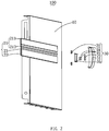
FIG. 1 is an isometric view of a rack system having an electrical supply according to an embodiment. -
FIG. 2 is an explored view of the rack system having the electrical supply ofFIG.1 . -
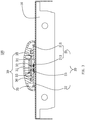
FIG. 3 is a cross sectional view of the rack system having the electrical supplyFIG. 1 . -
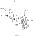
FIG. 4 is an explored view of a supplier of the rack system having the electrical supply ofFIG. 1 . - The present application is illustrated by way of example and not by way of limitation in the figures of the accompanying drawings. It should be noted that references to "an" or "one" embodiment in this application are not necessarily to the same embodiment, and such references mean at least one.
- Referring to
FIG. 1 to FIG. 4 , a rack system having anelectrical supply 100 is shown. The rack system having theelectrical supply 100 includes at least onebackboard 10, abus bar 20 mounted on thebackboard 10, and at least onesupplier 30 arranged on thebus bar 20. As is well known, the rack system having theelectrical supply 100 may include other modules, such as shelves rails, carrier elements, angle brackets, and so on, and wires electrically connecting thebus bar 20 with main powers, and wires electrically connecting thesupplier 30 to the lightings. These modules are well known by a person skilled in the art, and no need to explain in detail. - The
backboard 10 may be typically a flat plate and made of metal material, such as steel, and is inserted into the shelves rails for isolating different shelf spaces. Thebackboard 10 has a same configuration with that in the existing supermarket or the shopping mall. Therefore, it is no need to describe in detail. - The
bus bar 20 includes atrack body 21, twomagnetic strips 22 provided on thetrack body 21, and twocurrent conductors 23 spaced apart from each other and disposed on thetrace body 21. In order to prevent electric leakage, thetrack body 21 is made of insulating material, such as plastic. Thetrack body 21 may be arranged along the vertical direction of the shelves rails so that the lamps provided on a plurality of the carrier elements can be powered. In a cross section perpendicular to the extending direction of thetrack body 21, thetrack body 21 includes two magneticstrip receiving grooves 211 spaced apart from each other, and twoconductor receiving grooves 212 spaced apart from each other and disposed between the two magneticstrip receiving grooves 211. A width and a depth of the magneticstrip receiving grooves 211 are equal to a width and a thickness of themagnetic strip 22. Each of the twoconductor receiving grooves 212 includes two L-shaped side walls so that one of the twocurrent conductors 23 can be inserted into the two L-shaded side walls therebetween. Themagnetic strips 22 may be made of soft magnetic material so as to be suitably deformed during installation. Themagnetic strips 22 are attached to the magneticstrip receiving groove 211 via a method of adhering by glue, and so on. Thebus bar 20 can be directly attracted onto thebackboard 10 by themagnetic strips 22, and so, the installation of thebus bar 20 can be completed. The twocurrent conductors 23 are inserted in the twoconductor receiving grooves 212 respectively and are engaged with thecurrent conductors 23 by the L-shaped side walls of theconductor receiving grooves 212 so as to fix thecurrent conductors 23 therein. In order to make the thickness of thebus bar 20 become thinner, the center lines of themagnetic strips 22 overlap that of thecurrent conductors 23 along the arrangement direction thereof so as to reduce the whole thickness of thebus bar 20. The magneticstrip receiving grooves 211 and theconductor receiving grooves 212 are arranged on two opposite side walls of thetrack body 21, respectively - The
supplier 30 includes amain body 31, twoholding portions 32 extending from themain body 31, tworesilient contactors 33 disposed in themain body 31 and spaced apart from each other, acircuit board 34 mounted in themain body 31, acover 35 arranged on thecircuit board 34, twomagnetic columns 36 disposed in themain body 31 and arranged on both sides of the tworesilient contactors 33. Themain body 31 is provided with twoblind holes 311 for receiving the twomagnetic columns 36 respectively and areceiving chamber 312 disposed between the twoblind holes 311. Themain body 31 may be injected from a plastic material and is integrally formed with theblind holes 311 and thereceiving chamber 312. Thereceiving chamber 312 is configured for disposing thecircuit board 34 and the tworesilient contactors 33. The twoholding portions 32 may also be molded together with themain body 31 and extend towards thebus bar 30 and engage with the two side walls of thebus bar 20 which are perpendicular to the arrangement direction of themagnetic strips 22 and thecurrent conductors 23. Therefore, thesupplier 30 can be moved along the extending direction of thebus bar 20. Theresilient contactors 33 are prior art known to those skilled in the art and will be briefly described herein. Theresilient contactor 33 includes a sleeve, a spring disposed in the sleeve, and a circular or stepped contactor extending beyond one end of the sleeve. The contactor can be secured in the sleeve by compressing the sleeve port to form theresilient contactor 33. Thecircuit board 34 is prior art known to those skilled in the art and is configured for electrically connecting various electronic components, such as triodes, diodes, resistors, and the like. Theresilient contactors 33 may be fixed onto thecircuit board 34 and electrically connected to the outer wires. The method of fixing theresilient contactors 33 may be a soldering. Thecover 35 is arranged onto thecircuit board 34 to protect thecircuit board 34. It will be appreciated that thecover 35 is provided with two through holes therein for theresilient contactors 33. Themagnetic columns 36 may be fixed in the twoblind holes 311 respectively by interference fit. - In use, the
bus bar 20 is firstly attached to the appropriated position of thebackboard 10 by themagnetic strips 22, and thesupplier 30 is arranged onto thebus bar 20. The twomagnetic columns 36 are attached onto the twomagnetic strips 22 respectively, and the tworesilient contactors 33 are respectively abutted against the twomagnetic strips 22 when thesupplier 30 is mounted on thebus bar 20 so that the tworesilient contactors 33 are electrically connected to thecurrent conductors 33, respectively. In addition, when theresilient contactors 33 are electrically connected to thecurrent conductors 23, theresilient contactor 33 will pass through the gap formed between the two L-shaped side walls of theconductor receiving grooves 212. - Compared with the prior art, the rack system having the
electrical supply 100 provided by the present invention can make thebus bar 20 thinner by using the structure thereof, for example, a thickness of 2 mm to 3 mm. Therefore, thebus bar 20 can directly pass from the tolerance gap between thebackboard 10 and the carrier elements without disassembling the whole rack system, thereby completing the installation of thebus bar 20. And then, thesupplier 30 can be directly placed onto thebus bar 20 so as to achieve electrically connection. As a result, it is easy to install the rack system having the electrical supply so as to save cost and time.
Claims (10)
- A rack system having an electrical supply, comprising:at least one backboard (10);a bus bar (20) mounted on the backboard (10), the bus bar (20) comprising a track body (21), two magnetic strips (22) provided on the track body (21), and two current conductors (23) spaced apart from each other and disposed on the track body (21), in a cross section perpendicular to the extending direction of the track body (21) the track body (21) comprising two magnetic strip receiving grooves (211) spaced apart from each other, and two conductor receiving grooves (212) spaced apart from each other and disposed between the two magnetic strip receiving grooves(211), the magnetic strip receiving grooves (212) and the conductor receiving grooves (212) being arranged on two opposite side walls of the track body (21) respectively; anda supplier (30) arranged on the bus bar (20), the supplier (30) comprising two resilient contactors (33) spaced apart from each other, and two magnetic columns (36) arranged both sides of the resilient contactors (33), respectively, when the supplier (30) is mounted on the bus bar (20), the two magnetic columns (36) being attached onto the two magnetic strips (22) respectively, and the two resilient contactors (33) being respectively abutted against the two magnetic strips (22) so that the two resilient contactors (33) are electrically connected to the current conductor (23).
- The rack system having the electrical supply as claimed in claim 1, wherein the track body (21) is made of insulation material.
- The rack system having the electrical supply as claimed in claim 1 or 2, wherein the supplier (30) comprises a main body (31), and two holding portions (32) extending from the main body (31), the two holding portions (32) are engaged with the two side walls of the bus bar (20) which are perpendicular to the arrangement direction of the magnetic strips (22) and the current conductors (23).
- The rack system having the electrical supply as claimed in claim 3, wherein the main body (21) comprises two blind holes (311) provided thereon, and a receiving chamber (312) disposed between the two blind holes (311), the two blind holes (311) is configured for disposing the two magnetic columns (36) respectively, the receiving chamber (312) is configured to mount the resilient contactors (33).
- The rack system having the electrical supply as claimed in claim 4, wherein the supply (30) further comprises a circuit board (34) received in the receiving chamber (312), and a cover (35) arranged onto the circuit board (34), the resilient contactor (33) is welded to the circuit board (34) and protrudes out of the cover.
- The rack system having the electrical supply as claimed in one of the preceding claims, wherein the two magnetic strips (22) are made of soft magnetic material.
- The rack system having the electrical supply as claimed in one of the preceding claims, wherein the backboard (10) is made of metal material, the bus bar (20) is directly attached on the backboard (10) by the magnetic strips.
- The rack system having the electrical supply as claimed in one of the preceding claims, wherein in the cross section perpendicular to the extending direction of the track body (21), each of the two conductor receiving grooves (212) comprise an L-shaped side wall provided thereon.
- The rack system having the electrical supply as claimed in claim 8, wherein the resilient contactor (33) passes through the gap formed between the two L-shaped side walls of the conductor receiving grooves (212) and electrically connects to the current conductor (23).
- The rack system having the electrical supply as claimed in one of the preceding claims, wherein the center line of the magnetic strip (22) is overlapped with that of the current conductor (23) along the arrangement direction of the magnetic strip (22) and the current conductor (23).
Applications Claiming Priority (1)
| Application Number | Priority Date | Filing Date | Title |
|---|---|---|---|
| CN201710345195.7A CN107069356B (en) | 2017-05-16 | 2017-05-16 | Goods shelf electricity taking system |
Publications (2)
| Publication Number | Publication Date |
|---|---|
| EP3403532A1 EP3403532A1 (en) | 2018-11-21 |
| EP3403532B1 true EP3403532B1 (en) | 2019-08-28 |
Family
ID=59061902
Family Applications (1)
| Application Number | Title | Priority Date | Filing Date |
|---|---|---|---|
| EP17175978.0A Active EP3403532B1 (en) | 2017-05-16 | 2017-06-14 | Rack system having electrical supply |
Country Status (3)
| Country | Link |
|---|---|
| US (1) | US10172483B2 (en) |
| EP (1) | EP3403532B1 (en) |
| CN (1) | CN107069356B (en) |
Families Citing this family (13)
| Publication number | Priority date | Publication date | Assignee | Title |
|---|---|---|---|---|
| EP3305138A1 (en) * | 2016-10-05 | 2018-04-11 | Ariel Haroush | Modular powered secure product display mount |
| CN116154696A (en) * | 2017-11-01 | 2023-05-23 | 无锡蜜蜂照明科技有限公司 | A rack built-in power-taking system |
| DE102018105699B4 (en) * | 2018-03-13 | 2019-10-02 | Juvema Ag | Electrification system for hanging and / or shelving systems and hanging and / or shelving system with such electrification system |
| CN108332172B (en) * | 2018-03-29 | 2023-11-03 | 江南大学 | Electrified track power supply device |
| CN108539551B (en) * | 2018-03-29 | 2023-09-26 | 江南大学 | A power supply and extraction device for the inner wall of the track |
| CN108758579A (en) * | 2018-06-15 | 2018-11-06 | 柏赛塑胶科技(珠海保税区)有限公司 | A kind of circuit device that can flexibly lay |
| CN109088290B (en) * | 2018-08-21 | 2025-03-21 | 博洛尼智能科技(青岛)有限公司 | Furniture with movable conductive device and plate structure |
| GB2576625C (en) * | 2018-12-18 | 2021-12-22 | United Aluminium Ltd | An electrical connector |
| CN109965607B (en) * | 2019-04-28 | 2024-05-03 | 苏州市华仓塑料有限公司 | Rail power supply display rack plate |
| CN110854633A (en) * | 2019-10-22 | 2020-02-28 | 赛尔富电子有限公司 | Power supply device for display and exhibition |
| DE102020102488A1 (en) * | 2020-01-31 | 2021-08-05 | Wieland Electric Gmbh | Tapping a linear power distribution arrangement with a printed circuit board |
| CN114224133A (en) * | 2022-01-21 | 2022-03-25 | 广东三谷照明科技有限公司 | Combined display rack |
| US20230292921A1 (en) * | 2022-03-15 | 2023-09-21 | Dylan Bouterse | Shelf spine system |
Family Cites Families (15)
| Publication number | Priority date | Publication date | Assignee | Title |
|---|---|---|---|---|
| US5690415A (en) * | 1995-11-29 | 1997-11-25 | Stylmark, Inc. | Display light |
| US6855890B1 (en) * | 2003-07-22 | 2005-02-15 | Richard Vasichek | Brackets and methods for holding wires utilizing magnetic force |
| EP1571738A1 (en) * | 2004-03-03 | 2005-09-07 | Smart Di Martino Sandro | Modular electric connection system |
| DE102006002433B4 (en) * | 2006-01-11 | 2009-01-22 | Wilfried Pöllet | lighting system |
| JP2008243580A (en) * | 2007-03-27 | 2008-10-09 | Yamaha Corp | Power-feeding rail device |
| JP5288392B2 (en) * | 2007-06-11 | 2013-09-11 | コクヨ株式会社 | Power supply rail, power supply system, and display shelf |
| US7597565B1 (en) * | 2008-03-11 | 2009-10-06 | Textron Systems Corporation | Continuous sliding electrical contact tape |
| DE102011005735A1 (en) * | 2011-02-18 | 2012-08-23 | Ligaproduction Gmbh & Co. Kg | System for display stand, stall or exhibition stand and for shop fitting or for use in office or personal household, comprises wall, floor or ceiling element, carrier material and coating covering carrier material |
| GB2516853B (en) * | 2013-08-01 | 2016-09-14 | Clark-Ward Gary | A shelf power distribution apparatus |
| EP3044388A4 (en) * | 2013-09-09 | 2017-03-29 | DIRTT Environmental Solutions, Ltd. | Pass through shelf wall assembly |
| US9420901B2 (en) * | 2014-04-11 | 2016-08-23 | Sungal Corp. | Low voltage plug and play display system for general application in gondola systems |
| US9936826B2 (en) * | 2015-08-21 | 2018-04-10 | Apple Inc. | Modular wall system for displaying a product |
| CN205609903U (en) * | 2016-05-10 | 2016-09-28 | 无锡蜜蜂照明科技有限公司 | Electric system is got to magnetopause formula |
| CN205811207U (en) * | 2016-06-22 | 2016-12-14 | 赛尔富电子有限公司 | A kind of stand alone type electricity getting device and use the shelf of this electricity getting device |
| CN206850166U (en) * | 2017-05-16 | 2018-01-05 | 赛尔富电子有限公司 | A kind of shelf electricity getting system |
-
2017
- 2017-05-16 CN CN201710345195.7A patent/CN107069356B/en active Active
- 2017-06-14 EP EP17175978.0A patent/EP3403532B1/en active Active
- 2017-06-20 US US15/628,081 patent/US10172483B2/en active Active
Non-Patent Citations (1)
| Title |
|---|
| None * |
Also Published As
| Publication number | Publication date |
|---|---|
| US10172483B2 (en) | 2019-01-08 |
| US20180332979A1 (en) | 2018-11-22 |
| CN107069356A (en) | 2017-08-18 |
| EP3403532A1 (en) | 2018-11-21 |
| CN107069356B (en) | 2023-09-26 |
Similar Documents
| Publication | Publication Date | Title |
|---|---|---|
| EP3403532A1 (en) | Rack system having electrical supply | |
| US11528991B2 (en) | Shelf power supply system | |
| US9130326B2 (en) | Device for supplying electrical energy to a load, and system therefor | |
| EP3260018B1 (en) | Power supply system for shelving system | |
| EP3772245B1 (en) | Telescopic power supply track | |
| US9782018B2 (en) | Modular wall assembly for a cosmetic fixture system | |
| US7766502B2 (en) | Self-illuminated structural panel units and systems including the same | |
| US9337596B2 (en) | Systems and methods for aligning a ground stab | |
| RU2017145067A (en) | MODULAR STACKING SYSTEMS, MAGNETIC ELECTRICAL CONNECTORS, CONDUCTOR ASSEMBLIES AND INSTALLATION INSERTS | |
| EP3391782B1 (en) | A shelf electrical supply and shelf electrical supply system having same | |
| US20140003010A1 (en) | Power supply assembly of server | |
| US9800038B2 (en) | Wall structure and lighting system using the same | |
| US20190140388A1 (en) | Modular holding frame for plug connectors | |
| US20150155692A1 (en) | Busbar coupling device assembly | |
| EP3260020A1 (en) | Detached power supply apparatus and shelving system having same | |
| JP2012222168A (en) | Electronic module | |
| CN205811207U (en) | A kind of stand alone type electricity getting device and use the shelf of this electricity getting device | |
| JP2015049109A (en) | Linear conveyor | |
| US5593049A (en) | Support structure with wiring | |
| EP4205606B1 (en) | Shelf system with power supply device | |
| KR102180369B1 (en) | Bus bars for power supply of peripherals for information and communication devices for information and communication | |
| EP3211978B1 (en) | Power supply | |
| US20210098974A1 (en) | Creation of an electrical connection between components and a contacting plate | |
| JP3117584B2 (en) | Linear motor | |
| US20180375250A1 (en) | Shelf system having electrical supply |
Legal Events
| Date | Code | Title | Description |
|---|---|---|---|
| PUAI | Public reference made under article 153(3) epc to a published international application that has entered the european phase |
Free format text: ORIGINAL CODE: 0009012 |
|
| STAA | Information on the status of an ep patent application or granted ep patent |
Free format text: STATUS: REQUEST FOR EXAMINATION WAS MADE |
|
| 17P | Request for examination filed |
Effective date: 20171010 |
|
| AK | Designated contracting states |
Kind code of ref document: A1 Designated state(s): AL AT BE BG CH CY CZ DE DK EE ES FI FR GB GR HR HU IE IS IT LI LT LU LV MC MK MT NL NO PL PT RO RS SE SI SK SM TR |
|
| AX | Request for extension of the european patent |
Extension state: BA ME |
|
| RIC1 | Information provided on ipc code assigned before grant |
Ipc: H01R 25/14 20060101ALN20190109BHEP Ipc: F21W 131/301 20060101ALI20190109BHEP Ipc: A47F 11/10 20060101ALI20190109BHEP Ipc: A47B 97/00 20060101AFI20190109BHEP Ipc: H01R 13/62 20060101ALN20190109BHEP Ipc: A47F 5/00 20060101ALI20190109BHEP Ipc: A47B 96/02 20060101ALN20190109BHEP Ipc: F21V 17/10 20060101ALI20190109BHEP |
|
| GRAP | Despatch of communication of intention to grant a patent |
Free format text: ORIGINAL CODE: EPIDOSNIGR1 |
|
| STAA | Information on the status of an ep patent application or granted ep patent |
Free format text: STATUS: GRANT OF PATENT IS INTENDED |
|
| RIC1 | Information provided on ipc code assigned before grant |
Ipc: A47B 97/00 20060101AFI20190204BHEP Ipc: F21W 131/301 20060101ALI20190204BHEP Ipc: F21V 17/10 20060101ALI20190204BHEP Ipc: A47B 96/02 20060101ALN20190204BHEP Ipc: H01R 13/62 20060101ALN20190204BHEP Ipc: A47F 5/00 20060101ALI20190204BHEP Ipc: A47F 11/10 20060101ALI20190204BHEP Ipc: H01R 25/14 20060101ALN20190204BHEP |
|
| INTG | Intention to grant announced |
Effective date: 20190312 |
|
| RIN1 | Information on inventor provided before grant (corrected) |
Inventor name: XU, KAI Inventor name: CHEN, DONG |
|
| GRAS | Grant fee paid |
Free format text: ORIGINAL CODE: EPIDOSNIGR3 |
|
| GRAA | (expected) grant |
Free format text: ORIGINAL CODE: 0009210 |
|
| STAA | Information on the status of an ep patent application or granted ep patent |
Free format text: STATUS: THE PATENT HAS BEEN GRANTED |
|
| AK | Designated contracting states |
Kind code of ref document: B1 Designated state(s): AL AT BE BG CH CY CZ DE DK EE ES FI FR GB GR HR HU IE IS IT LI LT LU LV MC MK MT NL NO PL PT RO RS SE SI SK SM TR |
|
| REG | Reference to a national code |
Ref country code: GB Ref legal event code: FG4D |
|
| REG | Reference to a national code |
Ref country code: CH Ref legal event code: EP |
|
| REG | Reference to a national code |
Ref country code: AT Ref legal event code: REF Ref document number: 1171323 Country of ref document: AT Kind code of ref document: T Effective date: 20190915 |
|
| REG | Reference to a national code |
Ref country code: IE Ref legal event code: FG4D |
|
| REG | Reference to a national code |
Ref country code: DE Ref legal event code: R096 Ref document number: 602017006459 Country of ref document: DE |
|
| REG | Reference to a national code |
Ref country code: NL Ref legal event code: MP Effective date: 20190828 |
|
| REG | Reference to a national code |
Ref country code: LT Ref legal event code: MG4D |
|
| PG25 | Lapsed in a contracting state [announced via postgrant information from national office to epo] |
Ref country code: NO Free format text: LAPSE BECAUSE OF FAILURE TO SUBMIT A TRANSLATION OF THE DESCRIPTION OR TO PAY THE FEE WITHIN THE PRESCRIBED TIME-LIMIT Effective date: 20191128 Ref country code: LT Free format text: LAPSE BECAUSE OF FAILURE TO SUBMIT A TRANSLATION OF THE DESCRIPTION OR TO PAY THE FEE WITHIN THE PRESCRIBED TIME-LIMIT Effective date: 20190828 Ref country code: NL Free format text: LAPSE BECAUSE OF FAILURE TO SUBMIT A TRANSLATION OF THE DESCRIPTION OR TO PAY THE FEE WITHIN THE PRESCRIBED TIME-LIMIT Effective date: 20190828 Ref country code: BG Free format text: LAPSE BECAUSE OF FAILURE TO SUBMIT A TRANSLATION OF THE DESCRIPTION OR TO PAY THE FEE WITHIN THE PRESCRIBED TIME-LIMIT Effective date: 20191128 Ref country code: FI Free format text: LAPSE BECAUSE OF FAILURE TO SUBMIT A TRANSLATION OF THE DESCRIPTION OR TO PAY THE FEE WITHIN THE PRESCRIBED TIME-LIMIT Effective date: 20190828 Ref country code: PT Free format text: LAPSE BECAUSE OF FAILURE TO SUBMIT A TRANSLATION OF THE DESCRIPTION OR TO PAY THE FEE WITHIN THE PRESCRIBED TIME-LIMIT Effective date: 20191230 Ref country code: HR Free format text: LAPSE BECAUSE OF FAILURE TO SUBMIT A TRANSLATION OF THE DESCRIPTION OR TO PAY THE FEE WITHIN THE PRESCRIBED TIME-LIMIT Effective date: 20190828 Ref country code: SE Free format text: LAPSE BECAUSE OF FAILURE TO SUBMIT A TRANSLATION OF THE DESCRIPTION OR TO PAY THE FEE WITHIN THE PRESCRIBED TIME-LIMIT Effective date: 20190828 |
|
| PG25 | Lapsed in a contracting state [announced via postgrant information from national office to epo] |
Ref country code: ES Free format text: LAPSE BECAUSE OF FAILURE TO SUBMIT A TRANSLATION OF THE DESCRIPTION OR TO PAY THE FEE WITHIN THE PRESCRIBED TIME-LIMIT Effective date: 20190828 Ref country code: LV Free format text: LAPSE BECAUSE OF FAILURE TO SUBMIT A TRANSLATION OF THE DESCRIPTION OR TO PAY THE FEE WITHIN THE PRESCRIBED TIME-LIMIT Effective date: 20190828 Ref country code: GR Free format text: LAPSE BECAUSE OF FAILURE TO SUBMIT A TRANSLATION OF THE DESCRIPTION OR TO PAY THE FEE WITHIN THE PRESCRIBED TIME-LIMIT Effective date: 20191129 Ref country code: AL Free format text: LAPSE BECAUSE OF FAILURE TO SUBMIT A TRANSLATION OF THE DESCRIPTION OR TO PAY THE FEE WITHIN THE PRESCRIBED TIME-LIMIT Effective date: 20190828 Ref country code: RS Free format text: LAPSE BECAUSE OF FAILURE TO SUBMIT A TRANSLATION OF THE DESCRIPTION OR TO PAY THE FEE WITHIN THE PRESCRIBED TIME-LIMIT Effective date: 20190828 Ref country code: IS Free format text: LAPSE BECAUSE OF FAILURE TO SUBMIT A TRANSLATION OF THE DESCRIPTION OR TO PAY THE FEE WITHIN THE PRESCRIBED TIME-LIMIT Effective date: 20191228 |
|
| REG | Reference to a national code |
Ref country code: AT Ref legal event code: MK05 Ref document number: 1171323 Country of ref document: AT Kind code of ref document: T Effective date: 20190828 |
|
| PG25 | Lapsed in a contracting state [announced via postgrant information from national office to epo] |
Ref country code: TR Free format text: LAPSE BECAUSE OF FAILURE TO SUBMIT A TRANSLATION OF THE DESCRIPTION OR TO PAY THE FEE WITHIN THE PRESCRIBED TIME-LIMIT Effective date: 20190828 |
|
| PG25 | Lapsed in a contracting state [announced via postgrant information from national office to epo] |
Ref country code: AT Free format text: LAPSE BECAUSE OF FAILURE TO SUBMIT A TRANSLATION OF THE DESCRIPTION OR TO PAY THE FEE WITHIN THE PRESCRIBED TIME-LIMIT Effective date: 20190828 Ref country code: IT Free format text: LAPSE BECAUSE OF FAILURE TO SUBMIT A TRANSLATION OF THE DESCRIPTION OR TO PAY THE FEE WITHIN THE PRESCRIBED TIME-LIMIT Effective date: 20190828 Ref country code: DK Free format text: LAPSE BECAUSE OF FAILURE TO SUBMIT A TRANSLATION OF THE DESCRIPTION OR TO PAY THE FEE WITHIN THE PRESCRIBED TIME-LIMIT Effective date: 20190828 Ref country code: EE Free format text: LAPSE BECAUSE OF FAILURE TO SUBMIT A TRANSLATION OF THE DESCRIPTION OR TO PAY THE FEE WITHIN THE PRESCRIBED TIME-LIMIT Effective date: 20190828 Ref country code: RO Free format text: LAPSE BECAUSE OF FAILURE TO SUBMIT A TRANSLATION OF THE DESCRIPTION OR TO PAY THE FEE WITHIN THE PRESCRIBED TIME-LIMIT Effective date: 20190828 Ref country code: PL Free format text: LAPSE BECAUSE OF FAILURE TO SUBMIT A TRANSLATION OF THE DESCRIPTION OR TO PAY THE FEE WITHIN THE PRESCRIBED TIME-LIMIT Effective date: 20190828 |
|
| PG25 | Lapsed in a contracting state [announced via postgrant information from national office to epo] |
Ref country code: IS Free format text: LAPSE BECAUSE OF FAILURE TO SUBMIT A TRANSLATION OF THE DESCRIPTION OR TO PAY THE FEE WITHIN THE PRESCRIBED TIME-LIMIT Effective date: 20200224 Ref country code: SK Free format text: LAPSE BECAUSE OF FAILURE TO SUBMIT A TRANSLATION OF THE DESCRIPTION OR TO PAY THE FEE WITHIN THE PRESCRIBED TIME-LIMIT Effective date: 20190828 Ref country code: CZ Free format text: LAPSE BECAUSE OF FAILURE TO SUBMIT A TRANSLATION OF THE DESCRIPTION OR TO PAY THE FEE WITHIN THE PRESCRIBED TIME-LIMIT Effective date: 20190828 Ref country code: SM Free format text: LAPSE BECAUSE OF FAILURE TO SUBMIT A TRANSLATION OF THE DESCRIPTION OR TO PAY THE FEE WITHIN THE PRESCRIBED TIME-LIMIT Effective date: 20190828 |
|
| REG | Reference to a national code |
Ref country code: DE Ref legal event code: R097 Ref document number: 602017006459 Country of ref document: DE |
|
| PLBE | No opposition filed within time limit |
Free format text: ORIGINAL CODE: 0009261 |
|
| STAA | Information on the status of an ep patent application or granted ep patent |
Free format text: STATUS: NO OPPOSITION FILED WITHIN TIME LIMIT |
|
| PG2D | Information on lapse in contracting state deleted |
Ref country code: IS |
|
| 26N | No opposition filed |
Effective date: 20200603 |
|
| PG25 | Lapsed in a contracting state [announced via postgrant information from national office to epo] |
Ref country code: MC Free format text: LAPSE BECAUSE OF FAILURE TO SUBMIT A TRANSLATION OF THE DESCRIPTION OR TO PAY THE FEE WITHIN THE PRESCRIBED TIME-LIMIT Effective date: 20190828 |
|
| REG | Reference to a national code |
Ref country code: CH Ref legal event code: PL |
|
| PG25 | Lapsed in a contracting state [announced via postgrant information from national office to epo] |
Ref country code: LU Free format text: LAPSE BECAUSE OF NON-PAYMENT OF DUE FEES Effective date: 20200614 |
|
| REG | Reference to a national code |
Ref country code: BE Ref legal event code: MM Effective date: 20200630 |
|
| PG25 | Lapsed in a contracting state [announced via postgrant information from national office to epo] |
Ref country code: CH Free format text: LAPSE BECAUSE OF NON-PAYMENT OF DUE FEES Effective date: 20200630 Ref country code: LI Free format text: LAPSE BECAUSE OF NON-PAYMENT OF DUE FEES Effective date: 20200630 Ref country code: FR Free format text: LAPSE BECAUSE OF NON-PAYMENT OF DUE FEES Effective date: 20200630 Ref country code: IE Free format text: LAPSE BECAUSE OF NON-PAYMENT OF DUE FEES Effective date: 20200614 |
|
| PG25 | Lapsed in a contracting state [announced via postgrant information from national office to epo] |
Ref country code: BE Free format text: LAPSE BECAUSE OF NON-PAYMENT OF DUE FEES Effective date: 20200630 |
|
| PG25 | Lapsed in a contracting state [announced via postgrant information from national office to epo] |
Ref country code: MT Free format text: LAPSE BECAUSE OF FAILURE TO SUBMIT A TRANSLATION OF THE DESCRIPTION OR TO PAY THE FEE WITHIN THE PRESCRIBED TIME-LIMIT Effective date: 20190828 Ref country code: CY Free format text: LAPSE BECAUSE OF FAILURE TO SUBMIT A TRANSLATION OF THE DESCRIPTION OR TO PAY THE FEE WITHIN THE PRESCRIBED TIME-LIMIT Effective date: 20190828 |
|
| PG25 | Lapsed in a contracting state [announced via postgrant information from national office to epo] |
Ref country code: MK Free format text: LAPSE BECAUSE OF FAILURE TO SUBMIT A TRANSLATION OF THE DESCRIPTION OR TO PAY THE FEE WITHIN THE PRESCRIBED TIME-LIMIT Effective date: 20190828 |
|
| PG25 | Lapsed in a contracting state [announced via postgrant information from national office to epo] |
Ref country code: SI Free format text: LAPSE BECAUSE OF FAILURE TO SUBMIT A TRANSLATION OF THE DESCRIPTION OR TO PAY THE FEE WITHIN THE PRESCRIBED TIME-LIMIT Effective date: 20190828 |
|
| PGFP | Annual fee paid to national office [announced via postgrant information from national office to epo] |
Ref country code: GB Payment date: 20250630 Year of fee payment: 9 |
|
| PGFP | Annual fee paid to national office [announced via postgrant information from national office to epo] |
Ref country code: DE Payment date: 20250707 Year of fee payment: 9 |