EP3403364B1 - An apparatus and a method for managing full-duplex communication between a base station and a plurality of user equipments - Google Patents
An apparatus and a method for managing full-duplex communication between a base station and a plurality of user equipments Download PDFInfo
- Publication number
- EP3403364B1 EP3403364B1 EP16701746.6A EP16701746A EP3403364B1 EP 3403364 B1 EP3403364 B1 EP 3403364B1 EP 16701746 A EP16701746 A EP 16701746A EP 3403364 B1 EP3403364 B1 EP 3403364B1
- Authority
- EP
- European Patent Office
- Prior art keywords
- base station
- interference channel
- channel
- aggregate interference
- modified
- Prior art date
- Legal status (The legal status is an assumption and is not a legal conclusion. Google has not performed a legal analysis and makes no representation as to the accuracy of the status listed.)
- Active
Links
Images






Classifications
-
- H—ELECTRICITY
- H04—ELECTRIC COMMUNICATION TECHNIQUE
- H04L—TRANSMISSION OF DIGITAL INFORMATION, e.g. TELEGRAPHIC COMMUNICATION
- H04L5/00—Arrangements affording multiple use of the transmission path
- H04L5/14—Two-way operation using the same type of signal, i.e. duplex
-
- H—ELECTRICITY
- H04—ELECTRIC COMMUNICATION TECHNIQUE
- H04B—TRANSMISSION
- H04B17/00—Monitoring; Testing
- H04B17/30—Monitoring; Testing of propagation channels
- H04B17/309—Measuring or estimating channel quality parameters
- H04B17/345—Interference values
-
- H—ELECTRICITY
- H04—ELECTRIC COMMUNICATION TECHNIQUE
- H04B—TRANSMISSION
- H04B7/00—Radio transmission systems, i.e. using radiation field
- H04B7/02—Diversity systems; Multi-antenna system, i.e. transmission or reception using multiple antennas
- H04B7/04—Diversity systems; Multi-antenna system, i.e. transmission or reception using multiple antennas using two or more spaced independent antennas
- H04B7/0413—MIMO systems
- H04B7/0456—Selection of precoding matrices or codebooks, e.g. using matrices antenna weighting
-
- H—ELECTRICITY
- H04—ELECTRIC COMMUNICATION TECHNIQUE
- H04L—TRANSMISSION OF DIGITAL INFORMATION, e.g. TELEGRAPHIC COMMUNICATION
- H04L5/00—Arrangements affording multiple use of the transmission path
- H04L5/14—Two-way operation using the same type of signal, i.e. duplex
- H04L5/143—Two-way operation using the same type of signal, i.e. duplex for modulated signals
-
- H—ELECTRICITY
- H04—ELECTRIC COMMUNICATION TECHNIQUE
- H04L—TRANSMISSION OF DIGITAL INFORMATION, e.g. TELEGRAPHIC COMMUNICATION
- H04L5/00—Arrangements affording multiple use of the transmission path
- H04L5/003—Arrangements for allocating sub-channels of the transmission path
- H04L5/0058—Allocation criteria
- H04L5/0073—Allocation arrangements that take into account other cell interferences
Definitions
- the present invention relates to the field of telecommunications. More specifically, the present invention relates to an apparatus and a method for managing full-duplex communication between a base station and a plurality of user equipments.
- in-band full-duplex also known as full-duplex (FD)
- FD full-duplex
- HD time division duplex
- FDD frequency division duplex
- a full-duplex BS can improve the spectral efficiency because it uses the same time and frequency resources for uplink and downlink simultaneously.
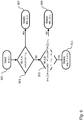
- Figure 1 shows an exemplary communication system 100 including two full-duplex base stations BS 0 and BS 1 simultaneously using the same time and frequency resources for uplink and downlink communication with user equipments 101a, b and user equipments 101c, d, respectively.
- enabling full-duplex base stations can potentially double the spectral efficiency at the cell.
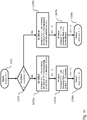
- the simultaneous transmission and reception in full-duplex base stations gives rise to a new interference scenario, e.g., inter-cell interference between neighboring co-channel base stations and self-interference at a single base station. Examples of inter-cell interference and self-interference are shown in figure 1 for the case of a communication system 100 with two BSs and in figure 2 for a more general case of a communication system 200 with seven BSs.
- co-channel base stations are typically synchronized such that all cells use the same uplink-downlink configuration with the transmission direction (either uplink or downlink) in all cells being time aligned.
- the main reason for a synchronous operation is that the usage of opposite transmission directions in neighboring co-channel cells would result in strong base station to base station interference ( Z. Shen, A. Khoryaev, E. Eriksson and X. Pan, "Dynamic uplink-downlink configuration and interference management in TD-LTE", IEEE Communications Magazine, November 2012 ). Consequently, inter-cell interference and the self-interference can be avoided in half-duplex networks by using an appropriate time and/or frequency slot assignment.
- ABS Almost Blank Subframe
- the base station DL precoder must consider the tradeoff between serving its DL users and minimizing the self-interference and inter-cell interference.
- Massive MIMO technology uses antenna arrays with the number of antenna elements being some orders of magnitude larger than current state-of-the-art MIMO technology, say 100 antennas or more ( F. Rusek, D. Persson, B. K. Lau, E. G. Larsson, T. L. Marzetta, O. Edfors, and F. Tufvesson, "Scaling up MIMO: Opportunities and challenges with very large arrays", IEEE Signal Processing Magazine, January 2013 and E. G. Larsson, F. Tufvesson, O. Edfors, and T. L. Marzetta, “Massive MIMO for Next Generation Wireless Systems", IEEE Communications Magazine, February 2014 ). Reaping the benefits of massive MIMO technology requires the channels of the active users to be nearly orthogonal or very low correlated.
- the invention relates to an apparatus for managing full-duplex communication between a base station and a set of user equipments, the base station comprising a plurality of transmitter antennas and a plurality of receiver antennas, the plurality of transmitter antennas being associated with a downlink communication channel H between the base station and the set of user equipments and a plurality of interference channels G i between the base station and a plurality of receiver antennas of a plurality of neighboring base stations, the apparatus comprising: a determiner configured to determine an aggregate interference channel G on the basis of the plurality of interference channels G i ; a modifier configured to iteratively modify the aggregate interference channel G to obtain a modified aggregate interference channel F under the constraint that a performance measure depending on the downlink communication channel H and the modified aggregate interference channel F meets a performance measure criterion, wherein the modified aggregate interference channel F spans a subspace of the space spanned by the aggregate interference channel G ; and a precoder (307) configured to precode signals to be
- an improved apparatus for managing full-duplex communication between a base station and a plurality of user equipments which allows the base station to serve the plurality of user equipments while mitigating the inter-cell interference that the base station generates at neighboring full-duplex base stations.
- the determiner is configured to determine the aggregate interference channel G on the basis of the plurality of interference channels G i and a self-interference channel G 0 between the plurality of transmitter antennas and a plurality of receiver antennas of the base station.
- the modifier is configured to modify the aggregate interference channel G to obtain the modified aggregate interference channel F under the constraint that a performance measure depending on the downlink communication channel H and the modified aggregate interference channel F meets a performance measure criterion by removing at least one column or row of the aggregate interference channel G that is the most aligned to the space spanned by the downlink communication channel H .
- the precoder is a regularized zero-forcing precoder, wherein the zero-forcing precoder is configured to adjust the degree of orthogonality to the space spanned by the modified aggregate interference channel F on the basis of a parameter associated with noise and/or interference level.
- the precoder matrix W depends on the modified aggregate interference channel F in such a way that the space spanned by the precoder matrix W is orthogonal to the space spanned by the modified aggregate interference channel F .
- the performance measure criterion comprises a performance measure criterion for each user equipment of the set of user equipments, wherein each performance measure criterion is defined by the following equation: QoS k HW ⁇ ⁇ k , wherein QoS k denotes a performance measure and ⁇ k denotes a performance measure threshold for the k -th user equipment of the set of user equipments.
- the performance measure can be a signal-to-interference-plus-noise ratio or a throughput defined as the effective downlink transmission rate between the base station and a user equipment.
- the modifier is configured to modify the aggregate interference channel G to obtain a modified aggregate interference channel F on the basis of information provided by at least one neighboring base station of the plurality of neighboring base stations.
- the information provided by the at least one neighboring base station of the plurality of neighboring base stations comprises information identifying at least one receiver antenna of at least one neighboring base station of the plurality of neighboring base stations for which interference should be mitigated.
- the modifier is configured to modify the aggregate interference channel G to obtain the modified aggregate interference channel F by removing a row or column of the aggregate interference channel G associated with the identified receiver antenna of the at least one neighboring base station of the plurality of neighboring base stations for which interference should be mitigated.
- the apparatus further comprises a scheduler configured to adjust the set of user equipments served by the base station on the basis of the modified aggregate interference channel F and/or the precoder matrix W .
- the apparatus is configured to provide information about the modified aggregate interference channel F to at least one neighboring base station of the plurality of neighboring base stations allowing the at least one neighboring base station, in particular, to reschedule its uplink users equipments.
- the invention relates to a base station comprising an apparatus according to the first aspect as such or any one of the first to eleventh implementation form thereof.
- the invention relates to a method for managing full-duplex communication between a base station and a set of user equipments, the base station comprising a plurality of transmitter antennas and a plurality of receiver antennas, the plurality of transmitter antennas being associated with a downlink communication channel H between the base station and the set of user equipments and a plurality of interference channels G i between the base station and a plurality of receiver antennas of a plurality of neighboring base stations, the method comprising the steps of: determining an aggregate interference channel G on the basis of the plurality of interference channels G i ; modifying the aggregate interference channel G to obtain a modified aggregate interference channel F under the constraint that a performance measure depending on the downlink communication channel H and the modified aggregate interference channel F meets a performance measure criterion, wherein the modified aggregate interference channel F spans a subspace of the space spanned by the aggregate interference channel G ; and precoding signals to be transmitted by the plurality of transmitter antennas on the basis of a precoder
- the method according to the third aspect of the invention can be performed by the apparatus according to the first aspect of the invention. Further features of the method according to the third aspect of the invention result directly from the functionality of the apparatus according to the first aspect of the invention and its different implementation forms described above.
- the invention relates to a computer program comprising program code for performing the method according to the third aspect of the invention or any of its implementation forms when executed on a computer.
- the invention can be implemented in hardware and/or software.
- a disclosure in connection with a described method may also hold true for a corresponding device or system configured to perform the method and vice versa.
- a corresponding device may include a unit to perform the described method step, even if such unit is not explicitly described or illustrated in the figures.
- the features of the various exemplary aspects described herein may be combined with each other, unless specifically noted otherwise.
- FIG. 3 shows a schematic diagram of an apparatus 301 according to an embodiment as part of a wireless communication system 300.
- the apparatus 301 is configured to manage the full-duplex communication between a base station BS 0 and a set of user equipments 101a,b, wherein the base station BS 0 comprises a plurality of transmitter antennas and a plurality of receiver antennas and wherein the plurality of transmitter antennas are associated with a downlink communication channel H between the base station BS 0 and the set of user equipments 101a,b and a plurality of interference channels G i between the base station BS 0 and a plurality of receiver antennas of a plurality of neighboring base stations BS i .
- the apparatus 301 can be implemented as a component of the base station BS 0 .
- the apparatus 301 comprises a determiner 303 configured to determine an aggregate interference channel G on the basis of the plurality of interference channels G i .
- the apparatus 301 comprises a modifier 305 configured to iteratively modify the aggregate interference channel G to obtain a modified aggregate interference channel F under the constraint that a performance measure depending on the downlink communication channel H and the modified aggregate interference channel F meets a performance measure criterion, wherein the modified aggregate interference channel F spans a subspace of the space spanned by the aggregate interference channel G .
- the apparatus 301 comprises a precoder 307 configured to precode signals to be transmitted by the plurality of transmitter antennas on the basis of a precoder matrix W in order to mitigate the interference at least at some of the neighboring base stations, wherein the precoder matrix W depends on the modified aggregate interference channel F .
- the apparatus 301 further comprises a scheduler 309 configured to adjust the set of user equipments 101a,b served by the base station BS 0 on the basis of the modified aggregate interference channel F and/or the precoder matrix W .
- Figure 4 shows a schematic diagram of a method 400 for managing full-duplex communication between a base station BS 0 and a set of user equipments 101a,b, wherein the base station BS 0 comprises a plurality of transmitter antennas and a plurality of receiver antennas and wherein the plurality of transmitter antennas are associated with a downlink communication channel H between the base station BS 0 and the set of user equipments 101a,b and a plurality of interference channels G i between the base station BS 0 and a plurality of receiver antennas of a plurality of neighboring base stations BS i .
- the method 400 comprises a first step 401 of determining an aggregate interference channel G on the basis of the plurality of interference channels G i .
- the method 400 comprises a further step 403 of modifying the aggregate interference channel G to obtain a modified aggregate interference channel F under the constraint that a performance measure depending on the downlink communication channel H and the modified aggregate interference channel F meets a performance measure criterion, wherein the modified aggregate interference channel F spans a subspace of the space spanned by the aggregate interference channel G .
- the method 400 comprises a further step 405 of precoding signals to be transmitted by the plurality of transmitter antennas on the basis of a precoder matrix W in order to mitigate the interference at least at some of the neighboring base stations, wherein the precoder matrix W depends on the modified aggregate interference channel F .
- the apparatus 301 is part of the base station BS 0 as shown, for instance, in figure 3 .
- the apparatus 301 can be a standalone unit in communication with the base station BS 0 .
- figure 3 shows a wireless communication network 300 comprising the apparatus 301 according to an embodiment, which is implemented as part of the base BS 0 .
- the apparatus 301 could be a standalone network entity in communication with the base station BS 0 and potentially other base stations BS i of the network 300 for centrally managing the full-duplex communication of these devices.
- the wireless communication network 300 shown in figure 3 consists of a plurality of full-duplex massive MIMO base stations ⁇ BS i ⁇ having M i antennas each.
- the users (or user equipments) served by a base station BS i can be either in full-duplex or half-duplex mode and a user in full-duplex mode can be both a DL user and an UL user at the same time and frequency.
- QoS k denotes a performance measure
- ⁇ k denotes a performance measure threshold for the k -th user equipment.
- the base station BS 0 While serving its K 0 DL users, the base station BS 0 creates self-interference to its own UL users and to the UL users served by its neighboring base stations where is defined as the set containing the indices of the neighboring BSs of the base station BS 0 .
- the matrix G 0 of dimensions R 0 ⁇ T 0 describes the self-interfering channel at the base station BS 0 and the matrix G i of dimensions R i ⁇ T 0 describes the propagation channel between the base station BS 0 and its neighboring base station BS i .
- the base station BS 0 creates interference in the aggregate interfering channel G defined as: with dimensions
- the base station BS 0 Since the base station BS 0 only uses K 0 degrees of freedom to serve its DL users, there are still T 0 - K 0 excess antennas which can be used as E 0 ⁇ T 0 - K 0 extra degrees of freedom to mitigate its own self-interference and also to mitigate the inter-cell interference created to its neighboring base stations. However, in the most general scenario, the number of the available extra degrees of freedom E 0 might not be large enough to completely cancel the aggregate interfering channel G . In that case, the base station BS 0 comprising the apparatus 301 can identify the spatial components (directions) that are creating the most harmful interference and that can be mitigated while still guaranteeing the QoS constraints of the DL users.
- these directions are identified by the apparatus 301 using a matrix F , which is obtained from G , optionally using information provided by neighboring base stations BS i . Since F is obtained from G , the matrix F is referred to herein as the final or modified aggregate interfering channel.
- aspects of an embodiment of the apparatus 301 as part of the base station BS i that is configured to serve its DL users and mitigate its self-interference and the inter-cell interference created at its neighboring base stations by exploiting the extra degrees of freedom resulting from the excess antennas of its massive MIMO array, will be described in the following.
- the number and/or the set of active DL users ⁇ 1, 2, ..., K 0 ⁇ can have been previously fixed by a scheduler 309 of the apparatus 301 or a higher-layer processing unit.
- this set could be updated by the scheduler 309 on the basis of the output of the modifier 305 and/or the precoder 307 of the apparatus 301 in order to obtain the best combination of feasible set of DL users and a desired interference mitigation level.
- the scheduler 309 determines the set of active DL users ⁇ 1, 2, ..., K 0 ⁇ (in block 601 in figure 6 ) and provides this set to the modifier 305.
- the precoder 307 determines the precoder matrix W on the basis of the modified aggregate interference channel (block 603 in figure 6 ).
- the apparatus 301 is configured to check whether the interference level associated with this precoder matrix W is acceptable or not (block 605 in figure 6 ). If this is the case, the apparatus 301 will serve the set of active DL users ⁇ 1, 2, ..., K 0 ⁇ (block 607 in figure 6 ). Otherwise, the scheduler 309 will determine a modified set of active DL users.
- the output information about mitigated interference can be exploited by the neighboring base stations BS i to update their respective sets of UL users.
- the neighboring base stations BS i can provide the apparatus 301, in particular the modifier 305, implemented as a component of the base station BS 0 , with information about the preferred interference to be mitigated (block 705 in figure 7 ).
- the apparatus 301 is configured to provide the final modified aggregate interference channel F to the the neighboring base stations BS i (blocks 707 and 709 of figure 7 ). On the basis of this information the neighboring base stations BS i can check whether the mitigated interference level is acceptable or not (block 711 of figure 7 ).
- the respective neighboring base station BS i can start serving its active UL users (block 715 of figure 7 ). Otherwise, a scheduler of the respective neighboring base station BS i can update its set of active UL users (block 715 of figure 7 ).
- the determiner 303 of the apparatus 301 is configured to compute the initial aggregate interfering channel G (0) on the basis of the set of neighboring base stations the interfering channels from the base station BS 0 to the neighboring base stations in , i.e., and the self-interference channel G 0 as follows (blocks 501 and 503 of figure 5 ):
- the self-interference channel G 0 can be an equivalent channel depending on the underlying self-interference cancelling approach that is used. For example, when the full-duplex operation uses analog cancellation or antenna isolation, it has been shown that the resulting dominant paths are a function of the type of analog canceller and isolation mechanism. Consequently, in an embodiment the base station BS 0 may choose to use the self-interference channel G 0 as the equivalent channel after applying analog cancellation and isolation.
- G 0 and G 0 do not have to represent necessarily a physical propagation channel. For instance, they can be unitary matrices describing the associated individual interfering subspaces.
- Equation (3) is in a very general form and embodiments of the invention implement the following simplifications thereof. If the self-interference is successfully managed at the antenna isolation and the analog canceller level, then in an embodiment the apparatus 301, implemented as component of the base station BS 0 , may choose not to include the self-interference channel G 0 in the calculation of the initial aggregate interfering channel G (0). If the interference generated to one of the neighboring co-channel base station, say BS j is weak, then in an embodiment the apparatus 301 implemented as component of the base station BS 0 may choose not to include the corresponding G j in the calculation of G (0) or, equivalently, remove j from the set . If G 0 and contain information about the underlying interfering subspaces, the operation in equation (3), must be understood as taking the union of all these interfering subspaces.
- Figure 8 shows in more detail a possible implementation of the block 505 shown in figure 5 in the apparatus 301 according to an embodiment implemented as component of the base station BS 0 , namely an implementation of the modifier 305 configured to iteratively obtain the final aggregate interfering channel F to be mitigated, given the DL channel H and the DL QoS constraints (block 806 of figure 8 ), the initial aggregate interfering channel G (0) (block 805 of figure 8 ), and possibly some information about interference mitigation preferences provided by the neighboring base stations (block 803 of figure 8 ).
- the apparatus 301 checks in block 807 the feasibility of constructing the precoder matrix W which guarantees the required quality of service constraints of the DL users while controlling the interference created through G ( n ) under some interference mitigation criterion. If this is feasible, the current aggregate interfering channel G ( n ) will be used as final aggregate interfering channel F (block 811 of figure 8 ). Otherwise, the current aggregate interfering channel G ( n ) will be updated (block 809 of figure 8 ). Optionally, information about the final aggregate interfering channel F and, thus, the mitigated interference can be provided to the neighboring base stations (block 813 of figure 8 ).
- the modifier 305 of the apparatus 301 is configured to iteratively obtain in block 809 of figure 8 the new aggregate interfering channel G ( n + 1) on the basis of the DL channel H between the base station BS 0 and its DL users and the current aggregate interfering channel G ( n ) by restricting it to span a subspace of the original space spanned by G ( n ).
- some information related to these operations can be shared with the base station BS 0 , so that this information can be used by the apparatus 301 implemented as a component of the base station BS 0 when calculating the final aggregate interfering channel F .
- this information can be shared with the base station BS 0 , for example, in the form of a set of vectors spanning such a subspace.
- this information can be shared with the base station BS 0 , for example, in the form of an ordered set of indices identifying the corresponding antennas.
- the base station BS 0 can share with its neighboring base stations the codebook index corresponding to the resulting final aggregated interfering channel F .
- the base station BS 0 can also share with its neighboring base stations information about span( F ), i.e., information about the mitigated interfering subspace. If the final aggregated interfering channel F was obtained by removing rows from the initial interfering channel G (0), then in an embodiment the base station BS 0 can share with its neighboring base stations the indices of the rows of G i that have been removed.
- all the optional outputs of the base station BS 0 in block 505 in figure 5 can be inputs to a corresponding block of a neighboring base station BS i and vice versa.
- the apparatus 301 implemented as a component of the base station BS 0 comprises a precoder 307 in the form of a zero-forcing (ZF) precoder to serve its K 0 DL users.
- ZF zero-forcing
- the precoder matrix W computed on the basis of equation (4) constitutes a possible embodiment for the block 509 shown in figure 5 .
- the apparatus 301 Given the channel H and the current aggregated interfering channel G ( n ) as inputs (block 901 of figure 9 ), the apparatus 301 is configured to check whether the conditions defined by equations (5) and (6) are met (blocks 903 and 905 of figure 9 ). If these conditions are met, the current aggregated interfering channel G ( n ) is provided as the final aggregated interfering channel F (block 911 of figure 9 ). Otherwise, the current aggregated interfering channel G ( n ) has to be further modified (blocks 907 and 909 of figure 9 ).
- Figure 10 shows further possible implementations of the block 809 of figure 8 for the case that no information from the neighboring base stations about the preferred interference to be mitigated is available to the base station BS 0 .
- the apparatus 301 checks whether the condition defined by equation (5) is met (block 1003 of figure 10 ).
- block 1005a or alternatively block 1005b of figure 10 the dimension of the subspace spanned by the aggregate interfering channel G ( n ) is reduced by resorting to its singular value decomposition.
- G ( n + 1) results from removing the weakest interfering directions from G ( n ) and/or the interfering directions in G ( n ) that are the most aligned to the DL channel H (blocks 1007a, 1009a, 1011a or alternatively blocks 1007b, 1009b, 1011b of figure 10 ).
- Figure 11 shows further possible implementations of the block 809 of figure 8 for the case that at least one, preferably several neighboring base station(s) BS i , provides to the base station BS 0 information in the form of a set(s) identifying the antenna elements of the neighboring base station(s) BS i , whose interference should be cancelled.
- the apparatus 301 implemented as a component of the base station BS 0 can calculate the initial ordered interference-free antenna set (0) including all elements of Let ( n ) denote the ordered interference-free antenna set, given that the interference created through G ( n ) is cancelled.
- the apparatus 301 checks whether the condition defined by equation (5) is met (block 1103 of figure 11 ). Then, G ( n + 1) is obtained by removing from G ( n ) the row corresponding to the T 0 ⁇ 1 channel connecting the T 0 transmit antennas of the base station BS 0 to the a i -th antenna element of the neighboring base station BS i , with a i being the first element in ( n ) (blocks 1105a, 1109a or alternatively blocks 1105b, 1109b of figure 11 ). The interference-free antenna set is updated as (blocks 1107a, 1109a or alternatively blocks 1107b, 1109b of figure 11 ).
- Embodiments of the invention provide, in particular, for the following advantages.
- Embodiments of the invention allow dealing with the following two types of interference which result from full-duplex operation: (i) inter-cell interference between base stations, and (ii) self-interference at a base station.
- embodiments of the invention are capable of performing interference mitigation while targeting no detrimental effect to the DL users.
- Embodiments of the invention are flexible in the sense that (i) different types of precoders can be applied, (ii) the input of different kinds of information regarding the interference of the network is possible (e.g. information about preferred interference to be mitigated), and (iii) different kinds of information regarding the interference created in the network can be provided (e.g.
- the final aggregate interfering channel that is computed by embodiments of the invention can be used by the system scheduler in order to update the set of served downlink users.
- the information about mitigated interference can be used by the schedulers of neighboring full-duplex base stations in order to update their respective sets of served uplink users.
Landscapes
- Engineering & Computer Science (AREA)
- Signal Processing (AREA)
- Computer Networks & Wireless Communication (AREA)
- Quality & Reliability (AREA)
- Physics & Mathematics (AREA)
- Electromagnetism (AREA)
- Mobile Radio Communication Systems (AREA)
Description
- Generally, the present invention relates to the field of telecommunications. More specifically, the present invention relates to an apparatus and a method for managing full-duplex communication between a base station and a plurality of user equipments.
- Due to the potential gains in spectral efficiency that can be achieved through simultaneous uplink (UL) and downlink (DL) communication within the entire frequency band, in-band full-duplex, also known as full-duplex (FD), is a promising candidate technology for next generation wireless communication systems. Commonly used half-duplex (HD) systems, such as time division duplex (TDD) or frequency division duplex (FDD) systems, employ orthogonal time resources or orthogonal frequency resources, respectively. A full-duplex BS can improve the spectral efficiency because it uses the same time and frequency resources for uplink and downlink simultaneously.
Figure 1 shows anexemplary communication system 100 including two full-duplex base stations BS0 and BS1 simultaneously using the same time and frequency resources for uplink and downlink communication withuser equipments 101a, b anduser equipments 101c, d, respectively. - Thus, enabling full-duplex base stations can potentially double the spectral efficiency at the cell. However, the simultaneous transmission and reception in full-duplex base stations gives rise to a new interference scenario, e.g., inter-cell interference between neighboring co-channel base stations and self-interference at a single base station. Examples of inter-cell interference and self-interference are shown in
figure 1 for the case of acommunication system 100 with two BSs and infigure 2 for a more general case of acommunication system 200 with seven BSs. - In currently deployed wireless systems, co-channel base stations are typically synchronized such that all cells use the same uplink-downlink configuration with the transmission direction (either uplink or downlink) in all cells being time aligned. The main reason for a synchronous operation is that the usage of opposite transmission directions in neighboring co-channel cells would result in strong base station to base station interference (Z. Shen, A. Khoryaev, E. Eriksson and X. Pan, "Dynamic uplink-downlink configuration and interference management in TD-LTE", IEEE Communications Magazine, November 2012). Consequently, inter-cell interference and the self-interference can be avoided in half-duplex networks by using an appropriate time and/or frequency slot assignment. This is not the case in full-duplex BS deployments, because simultaneous co-channel uplink and downlink transmissions in all base stations are the essence of the full-duplex operation. In consequence, the self-interference and the base station to base station inter-cell interference must be explicitly addressed in order to enable full-duplex networks and leverage the potential increase of spectral efficiency (S. Goyal, P. Liu, S. S Panwar, R. A. DiFazio, R. Yang, and E. Bala "Full duplex cellular systems: Will doubling interference prevent doubling capacity?", IEEE Communications Magazine, May 2015 and Y. S. Choi and H. Shirani-Mehr "Simultaneous Transmission and Reception: Algorithm, Design and System Level Performance", IEEE Transactions on Wireless Communications, December 2013).
- Current solutions for interference mitigation in half-duplex systems have disadvantages when applied to the full-duplex scenario. For example, if one applies an Almost Blank Subframe (ABS) solution like the one proposed in LTE (K. I. Pedersen, Y. Wang, B. Soret and F. Frederiksen, "eICIC functionality and performance for LTE HetNet co-channel deployments", in Proc. IEEE Vehicular Technology Conference Fall, 2012), where a set of the interfering nodes remains silent during a period of time, the full-duplex configuration ends up being reverted (completely or partially) to a half-duplex configuration hence losing some or all of the full-duplex gain. Similarly, solutions like frequency reuse or fractional frequency reuse as disclosed, for instance, in T. Novlan, J. G. Andrews, I. Sohn, R. K. Ganti and A. Ghosh, "Comparison of fractional frequency reuse approaches in the OFDMA cellular downlink", in Proc. IEEE Global Telecommunication Conference, 2010, which do an orthogonal frequency assignment to regions that suffer from interference, end up reverting the full-duplex assignment (completely or partially) to a half-duplex one.
- Conventional full-duplex solutions mainly consider the problem of self-interference cancellation while disregarding the problem of inter-cell interference. The self-interference received at a full-duplex base station is due to the received signal from its own transmissions, whereas the inter-cell interference is due to the received signal from the transmissions of neighboring co-channel base stations. In the case of multiple antenna full-duplex base stations, the use of large number of antennas has only been leveraged for reducing the self-interference, i.e., for achieving spatial self-interference cancellation (B. Yin, M. Studer, J. R. Cavallaro and J. Lilleberg, "Full-duplex in large-scale wireless systems", in Proc. Asilomar Conference on Signal Systems and Computers, November 2013 and H. Q. Ngo, H. A. Surawera, M. Matthaiou and E. G. Larsson, "Multipair full-duplex relaying with massive arrays and linear processing," available online http://arxiv.org/abs/1405.1063).
- Generally, conventional spatial self-interference cancelling solutions implicitly assume that the size of the antenna array is larger than the number of users to be served in the cell plus the number of independent self-interference signals to be cancelled. This premise, however, does not usually hold for the case of inter-cell interference. This is because the number of co-channel neighboring base stations' antennas and, thus, the number of independent interfering directions to be cancelled is very high and can potentially increase with the size of the base stations arrays. Hence, extending the self-interference cancellation solutions disclosed in the above-referenced papers by Yin et al. and Ngo et al. for simultaneously solving the self-interference and the inter-cell interference problems is difficult. Indeed, the case when the number of degrees of freedom provided by the large scale multi antenna configuration is smaller than the number required for interference nulling between full-duplex base stations has not been considered. In such a case, the base station DL precoder must consider the tradeoff between serving its DL users and minimizing the self-interference and inter-cell interference.
- Massive MIMO technology uses antenna arrays with the number of antenna elements being some orders of magnitude larger than current state-of-the-art MIMO technology, say 100 antennas or more (F. Rusek, D. Persson, B. K. Lau, E. G. Larsson, T. L. Marzetta, O. Edfors, and F. Tufvesson, "Scaling up MIMO: Opportunities and challenges with very large arrays", IEEE Signal Processing Magazine, January 2013 and E. G. Larsson, F. Tufvesson, O. Edfors, and T. L. Marzetta, "Massive MIMO for Next Generation Wireless Systems", IEEE Communications Magazine, February 2014). Reaping the benefits of massive MIMO technology requires the channels of the active users to be nearly orthogonal or very low correlated. Real channel measurements campaigns reported in Xiang Gao; Edfors, O.; Rusek, F.; Tufvesson, F., "Linear Pre-Coding Performance in Measured Very-Large MIMO Channels," in Vehicular Technology Conference (VTC Fall), 2011 IEEE , vol., no., pp.1-5, 5-8 Sept. 2011 and Hoydis, J.; Hoek, C.; Wild, T.; ten Brink, S., "Channel measurements for large antenna arrays," in Wireless Communication Systems (ISWCS), 2012 International Symposium on , vol., no., pp.811-815, 28-31 Aug. 2012 indicate that channel correlation cannot be arbitrarily reduced by increasing the number of antennas, which means that usual propagation environments offer a limited number of physical directions or degrees of freedom. Hence, the number of users that can be effectively served within a cell is limited (around 20 as reported in Hoydis et al. 2012) independently of the number of antennas at the massive MIMO base station (typically larger than 100). This leads to the concept of excess antennas. The number of excess antennas is given by the number of transmit antennas minus the number of active DL users.
- The use of excess antennas in a massive MIMO base station to mitigate the inter-cell interference has been considered in J. Hoydis, K. Hosseni, S. T. Brink and M. Debbah, "Making smart use of excess antennas: Massive MIMO, small cells, and TDD", Bell Labs Technical Journal 18(2), 5-21, 2013 in the context of HD two-tier heterogeneous networks. However, the solutions provided in Hoydis et al. 2013 hold only for the case where all of the antennas in the array are either in transmitter mode or in receiver mode. Hence, the solutions provided in Hoydis et al. 2013 apply only to a half-duplex scenario.
- In the light of the above, there is a need for an improved apparatus and method for managing full-duplex communication between a base station and a plurality of user equipments allowing the base station to serve the plurality of user equipments while mitigating the inter-cell interference that the base station generates at neighboring full-duplex base stations.
- It is an object of the invention to provide an improved apparatus and method for managing full-duplex communication between a base station and a plurality of user equipments allowing the base station to serve the plurality of user equipments while mitigating the inter-cell interference that the base station generates at neighboring full-duplex base stations.
- The foregoing and other objects are achieved by the subject matter of the independent claims. Further implementation forms are apparent from the dependent claims, the description and the figures.
- According to a first aspect, the invention relates to an apparatus for managing full-duplex communication between a base station and a set of user equipments, the base station comprising a plurality of transmitter antennas and a plurality of receiver antennas, the plurality of transmitter antennas being associated with a downlink communication channel H between the base station and the set of user equipments and a plurality of interference channels G i between the base station and a plurality of receiver antennas of a plurality of neighboring base stations, the apparatus comprising: a determiner configured to determine an aggregate interference channel G on the basis of the plurality of interference channels G i ; a modifier configured to iteratively modify the aggregate interference channel G to obtain a modified aggregate interference channel F under the constraint that a performance measure depending on the downlink communication channel H and the modified aggregate interference channel F meets a performance measure criterion, wherein the modified aggregate interference channel F spans a subspace of the space spanned by the aggregate interference channel G ; and a precoder (307) configured to precode signals to be transmitted by the plurality of transmitter antennas on the basis of a precoder matrix W , in order to mitigate the interference at least at some of the neighboring base stations, wherein the precoder matrix W depends on the modified aggregate interference channel F .
- Thus, an improved apparatus for managing full-duplex communication between a base station and a plurality of user equipments is provided, which allows the base station to serve the plurality of user equipments while mitigating the inter-cell interference that the base station generates at neighboring full-duplex base stations.
- In a first possible implementation form of the apparatus according to the first aspect as such, the determiner is configured to determine the aggregate interference channel G on the basis of the plurality of interference channels G i and a self-interference channel G 0 between the plurality of transmitter antennas and a plurality of receiver antennas of the base station.
- In a second possible implementation form of the apparatus according to the first aspect as such or the first implementation form thereof, the modifier is configured to modify the aggregate interference channel G to obtain the modified aggregate interference channel F under the constraint that a performance measure depending on the downlink communication channel H and the modified aggregate interference channel F meets a performance measure criterion by removing at least one column or row of the aggregate interference channel G that is the most aligned to the space spanned by the downlink communication channel H .
- In a third possible implementation form of the apparatus according to the first aspect as such or the first or second implementation form thereof, the precoder is a regularized zero-forcing precoder, wherein the zero-forcing precoder is configured to adjust the degree of orthogonality to the space spanned by the modified aggregate interference channel F on the basis of a parameter associated with noise and/or interference level.
- In a fourth possible implementation form of the apparatus according to the first aspect as such or any one of the first to third implementation form thereof, the precoder matrix W depends on the modified aggregate interference channel F in such a way that the space spanned by the precoder matrix W is orthogonal to the space spanned by the modified aggregate interference channel F .
- Thus, in an implementation form the precoder matrix W can be defined by the following equation:

- In a fifth possible implementation form of the apparatus according to the first aspect as such or any one of the first to fourth implementation form thereof, the performance measure criterion comprises a performance measure criterion for each user equipment of the set of user equipments, wherein each performance measure criterion is defined by the following equation:

- In an implementation form, the performance measure can be a signal-to-interference-plus-noise ratio or a throughput defined as the effective downlink transmission rate between the base station and a user equipment.
- In a sixth possible implementation form of the apparatus according to the first aspect as such or any one of the first to fifth implementation form thereof, the modifier is configured to modify the aggregate interference channel G to obtain the modified aggregate interference channel F by determining a singular value decomposition of the aggregate interference channel G of the form G = UΛVH comprising a diagonal matrix Λ, modifying at least one of the singular values of the diagonal matrix Λ to obtain a modified diagonal matrix Λ*, and by determining the modified aggregate interference channel F as F = UΛ ∗ VH .
- In a seventh possible implementation form of the apparatus according to the first aspect as such or any one of the first to sixth implementation form thereof, the modifier is configured to modify the aggregate interference channel G to obtain a modified aggregate interference channel F on the basis of information provided by at least one neighboring base station of the plurality of neighboring base stations.
- In an eighth possible implementation form of the apparatus according to the seventh implementation form of the first aspect, the information provided by the at least one neighboring base station of the plurality of neighboring base stations comprises information identifying at least one receiver antenna of at least one neighboring base station of the plurality of neighboring base stations for which interference should be mitigated.
- In a ninth possible implementation form of the apparatus according to the eighth implementation form of the first aspect, the modifier is configured to modify the aggregate interference channel G to obtain the modified aggregate interference channel F by removing a row or column of the aggregate interference channel G associated with the identified receiver antenna of the at least one neighboring base station of the plurality of neighboring base stations for which interference should be mitigated.
- In a tenth possible implementation form of the apparatus according to the first aspect as such or any one of the first to ninth implementation form thereof, the apparatus further comprises a scheduler configured to adjust the set of user equipments served by the base station on the basis of the modified aggregate interference channel F and/or the precoder matrix W .
- In an eleventh possible implementation form of the apparatus according to the first aspect as such or any one of the first to tenth implementation form thereof, the apparatus is configured to provide information about the modified aggregate interference channel F to at least one neighboring base station of the plurality of neighboring base stations allowing the at least one neighboring base station, in particular, to reschedule its uplink users equipments.
- According to a second aspect, the invention relates to a base station comprising an apparatus according to the first aspect as such or any one of the first to eleventh implementation form thereof.
- According to a third aspect, the invention relates to a method for managing full-duplex communication between a base station and a set of user equipments, the base station comprising a plurality of transmitter antennas and a plurality of receiver antennas, the plurality of transmitter antennas being associated with a downlink communication channel H between the base station and the set of user equipments and a plurality of interference channels G i between the base station and a plurality of receiver antennas of a plurality of neighboring base stations, the method comprising the steps of: determining an aggregate interference channel G on the basis of the plurality of interference channels G i ; modifying the aggregate interference channel G to obtain a modified aggregate interference channel F under the constraint that a performance measure depending on the downlink communication channel H and the modified aggregate interference channel F meets a performance measure criterion, wherein the modified aggregate interference channel F spans a subspace of the space spanned by the aggregate interference channel G ; and precoding signals to be transmitted by the plurality of transmitter antennas on the basis of a precoder matrix W in order to mitigate the interference at least at some of the neighboring base stations, wherein the precoder matrix W depends on the modified aggregate interference channel F .
- The method according to the third aspect of the invention can be performed by the apparatus according to the first aspect of the invention. Further features of the method according to the third aspect of the invention result directly from the functionality of the apparatus according to the first aspect of the invention and its different implementation forms described above.
- According to a fourth aspect the invention relates to a computer program comprising program code for performing the method according to the third aspect of the invention or any of its implementation forms when executed on a computer.
- The invention can be implemented in hardware and/or software.
- Further embodiments of the invention will be described with respect to the following figures, wherein:
-
Fig. 1 shows a schematic diagram of a communication system comprising a plurality of base stations and a plurality of user equipments; -
Fig. 2 shows a schematic diagram of a communication system comprising a plurality of base stations; -
Fig. 3 shows a schematic diagram of an apparatus for managing full-duplex communication between a base station and a plurality of user equipments according to an embodiment as part of a communication system; -
Fig. 4 shows a schematic diagram illustrating a method for managing full-duplex communication between a base station and a plurality of user equipments according to an embodiment; -
Fig. 5 shows a schematic diagram illustrating different aspects of an apparatus for managing full-duplex communication between a base station and a plurality of user equipments according to an embodiment; -
Fig. 6 shows a schematic diagram illustrating different aspects of an apparatus for managing full-duplex communication between a base station and a plurality of user equipments according to an embodiment; -
Fig. 7 shows a schematic diagram illustrating different aspects of an apparatus for managing full-duplex communication between a base station and a plurality of user equipments according to an embodiment; -
Fig. 8 shows a schematic diagram illustrating different aspects of an apparatus for managing full-duplex communication between a base station and a plurality of user equipments according to an embodiment; -
Fig. 9 shows a schematic diagram illustrating different aspects of an apparatus for managing full-duplex communication between a base station and a plurality of user equipments according to an embodiment; -
Fig. 10 shows a schematic diagram illustrating different aspects of an apparatus for managing full-duplex communication between a base station and a plurality of user equipments according to an embodiment; and -
Fig. 11 shows a schematic diagram illustrating different aspects of an apparatus for managing full-duplex communication between a base station and a plurality of user equipments according to an embodiment. - In the various figures, identical reference signs are used for identical or at least functionally equivalent features.
- In the following description, reference is made to the accompanying drawings, which form part of the disclosure, and in which are shown, by way of illustration, specific aspects in which the present invention may be placed. It is understood that other aspects may be utilized and structural or logical changes may be made without departing from the scope of the present invention. The following detailed description, therefore, is not to be taken in a limiting sense, as the scope of the present invention is defined by the appended claims.
- For instance, it is understood that a disclosure in connection with a described method may also hold true for a corresponding device or system configured to perform the method and vice versa. For example, if a specific method step is described, a corresponding device may include a unit to perform the described method step, even if such unit is not explicitly described or illustrated in the figures. Further, it is understood that the features of the various exemplary aspects described herein may be combined with each other, unless specifically noted otherwise.
-
Figure 3 shows a schematic diagram of anapparatus 301 according to an embodiment as part of awireless communication system 300. Theapparatus 301 is configured to manage the full-duplex communication between a base station BS0 and a set ofuser equipments 101a,b, wherein the base station BS0 comprises a plurality of transmitter antennas and a plurality of receiver antennas and wherein the plurality of transmitter antennas are associated with a downlink communication channel H between the base station BS0 and the set ofuser equipments 101a,b and a plurality of interference channels G i between the base station BS0 and a plurality of receiver antennas of a plurality of neighboring base stations BS i . For the sake of clarity only one neighboring base station BS i is shown infigure 3 . In an embodiment, theapparatus 301 can be implemented as a component of the base station BS0. - The
apparatus 301 comprises adeterminer 303 configured to determine an aggregate interference channel G on the basis of the plurality of interference channels G i . Moreover, theapparatus 301 comprises amodifier 305 configured to iteratively modify the aggregate interference channel G to obtain a modified aggregate interference channel F under the constraint that a performance measure depending on the downlink communication channel H and the modified aggregate interference channel F meets a performance measure criterion, wherein the modified aggregate interference channel F spans a subspace of the space spanned by the aggregate interference channel G . Moreover, theapparatus 301 comprises aprecoder 307 configured to precode signals to be transmitted by the plurality of transmitter antennas on the basis of a precoder matrix W in order to mitigate the interference at least at some of the neighboring base stations, wherein the precoder matrix W depends on the modified aggregate interference channel F . - In an embodiment, the
apparatus 301 further comprises ascheduler 309 configured to adjust the set ofuser equipments 101a,b served by the base station BS0 on the basis of the modified aggregate interference channel F and/or the precoder matrix W . -
Figure 4 shows a schematic diagram of amethod 400 for managing full-duplex communication between a base station BS0 and a set ofuser equipments 101a,b, wherein the base station BS0 comprises a plurality of transmitter antennas and a plurality of receiver antennas and wherein the plurality of transmitter antennas are associated with a downlink communication channel H between the base station BS0 and the set ofuser equipments 101a,b and a plurality of interference channels G i between the base station BS0 and a plurality of receiver antennas of a plurality of neighboring base stations BS i . - The
method 400 comprises afirst step 401 of determining an aggregate interference channel G on the basis of the plurality of interference channels G i . Themethod 400 comprises afurther step 403 of modifying the aggregate interference channel G to obtain a modified aggregate interference channel F under the constraint that a performance measure depending on the downlink communication channel H and the modified aggregate interference channel F meets a performance measure criterion, wherein the modified aggregate interference channel F spans a subspace of the space spanned by the aggregate interference channel G . Themethod 400 comprises afurther step 405 of precoding signals to be transmitted by the plurality of transmitter antennas on the basis of a precoder matrix W in order to mitigate the interference at least at some of the neighboring base stations, wherein the precoder matrix W depends on the modified aggregate interference channel F . - Further implementation forms, embodiments and aspects of the
apparatus 301 and themethod 400 will be described in the following, in particular embodiments, where theapparatus 301 is part of the base station BS0 as shown, for instance, infigure 3 . In other embodiments, theapparatus 301 can be a standalone unit in communication with the base station BS0. - As already mentioned above,
figure 3 shows awireless communication network 300 comprising theapparatus 301 according to an embodiment, which is implemented as part of the base BS0. One will appreciate that in other embodiments theapparatus 301 could be a standalone network entity in communication with the base station BS0 and potentially other base stations BS i of thenetwork 300 for centrally managing the full-duplex communication of these devices. - The
wireless communication network 300 shown infigure 3 consists of a plurality of full-duplex massive MIMO base stations {BS i } having Mi antennas each. In an embodiment, a base station BS i serves Ki DL user equipments or users using


- In an embodiment, the base station BS0 serves K 0 DL users (or user equipments) through the DL channel H of dimensions K 0 × T 0 and rank( H ) = K 0, while guaranteeing some individual performance measure, in particular, a quality-of-service (QoS) constraint for each user:

- While serving its K 0 DL users, the base station BS0 creates self-interference to its own UL users and to the UL users served by its neighboring base stations
 is defined as the set containing the indices of the neighboring BSs of the base station BS0. The matrix G 0 of dimensions R 0 × T 0 describes the self-interfering channel at the base station BS0 and the matrix G i of dimensions Ri × T 0 describes the propagation channel between the base station BS0 and its neighboring base station BS i . In this case, the base station BS0 creates interference in the aggregate interfering channel G defined as:


- Since the base station BS0 only uses K 0 degrees of freedom to serve its DL users, there are still T 0 - K 0 excess antennas which can be used as E 0 ≤ T 0 - K 0 extra degrees of freedom to mitigate its own self-interference and also to mitigate the inter-cell interference created to its neighboring base stations. However, in the most general scenario, the number of the available extra degrees of freedom E 0 might not be large enough to completely cancel the aggregate interfering channel G . In that case, the base station BS0 comprising the
apparatus 301 can identify the spatial components (directions) that are creating the most harmful interference and that can be mitigated while still guaranteeing the QoS constraints of the DL users. - In an embodiment, these directions are identified by the
apparatus 301 using a matrix F , which is obtained from G , optionally using information provided by neighboring base stations BS i . Since F is obtained from G , the matrix F is referred to herein as the final or modified aggregate interfering channel. - Under reference to
figure 5 , aspects of an embodiment of theapparatus 301 as part of the base station BS i , that is configured to serve its DL users and mitigate its self-interference and the inter-cell interference created at its neighboring base stations by exploiting the extra degrees of freedom resulting from the excess antennas of its massive MIMO array, will be described in the following. - In an embodiment, the number and/or the set of active DL users {1, 2, ..., K 0} can have been previously fixed by a
scheduler 309 of theapparatus 301 or a higher-layer processing unit. For instance, in an embodiment, this set could be updated by thescheduler 309 on the basis of the output of themodifier 305 and/or theprecoder 307 of theapparatus 301 in order to obtain the best combination of feasible set of DL users and a desired interference mitigation level. Such an embodiment is shown infigure 6 . Thescheduler 309 determines the set of active DL users {1, 2, ..., K 0} (inblock 601 infigure 6 ) and provides this set to themodifier 305. On the basis of this set of active DL users theprecoder 307 determines the precoder matrix W on the basis of the modified aggregate interference channel (block 603 infigure 6 ). Theapparatus 301 is configured to check whether the interference level associated with this precoder matrix W is acceptable or not (block 605 infigure 6 ). If this is the case, theapparatus 301 will serve the set of active DL users {1, 2, ..., K 0} (block 607 infigure 6 ). Otherwise, thescheduler 309 will determine a modified set of active DL users. - In an embodiment, the output information about mitigated interference can be exploited by the neighboring base stations BS i to update their respective sets of UL users. Such an embodiment is illustrated in
Figure 7 . In an embodiment, the neighboring base stations BS i can provide theapparatus 301, in particular themodifier 305, implemented as a component of the base station BS0, with information about the preferred interference to be mitigated (block 705 infigure 7 ). In an embodiment, theapparatus 301 is configured to provide the final modified aggregate interference channel F to the the neighboring base stations BS i (blocks figure 7 ). On the basis of this information the neighboring base stations BS i can check whether the mitigated interference level is acceptable or not (block 711 offigure 7 ). If this is the case, the respective neighboring base station BS i can start serving its active UL users (block 715 offigure 7 ). Otherwise, a scheduler of the respective neighboring base station BS i can update its set of active UL users (block 715 offigure 7 ). - Referring back to
figure 5 , in an embodiment, thedeterminer 303 of theapparatus 301 is configured to compute the initial aggregate interfering channel G (0) on the basis of the set of neighboring base stations , i.e.,
blocks figure 5 ):
- In an embodiment, the self-interference channel G 0 can be an equivalent channel depending on the underlying self-interference cancelling approach that is used. For example, when the full-duplex operation uses analog cancellation or antenna isolation, it has been shown that the resulting dominant paths are a function of the type of analog canceller and isolation mechanism. Consequently, in an embodiment the base station BS0 may choose to use the self-interference channel G 0 as the equivalent channel after applying analog cancellation and isolation.
- Similarly, G 0 and

- Equation (3) is in a very general form and embodiments of the invention implement the following simplifications thereof. If the self-interference is successfully managed at the antenna isolation and the analog canceller level, then in an embodiment the
apparatus 301, implemented as component of the base station BS0, may choose not to include the self-interference channel G 0 in the calculation of the initial aggregate interfering channel G (0). If the interference generated to one of the neighboring co-channel base station, say BS j is weak, then in an embodiment theapparatus 301 implemented as component of the base station BS0 may choose not to include the corresponding G j in the calculation of G (0) or, equivalently, remove j from the set. If G 0 and
-
Figure 8 shows in more detail a possible implementation of theblock 505 shown infigure 5 in theapparatus 301 according to an embodiment implemented as component of the base station BS0, namely an implementation of themodifier 305 configured to iteratively obtain the final aggregate interfering channel F to be mitigated, given the DL channel H and the DL QoS constraints (block 806 offigure 8 ), the initial aggregate interfering channel G (0) (block 805 offigure 8 ), and possibly some information about interference mitigation preferences provided by the neighboring base stations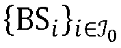
figure 8 ). - Given the DL channel H between the base station BS0 and its DL users and the current aggregate interfering channel G (n), the
apparatus 301 checks inblock 807 the feasibility of constructing the precoder matrix W which guarantees the required quality of service constraints of the DL users while controlling the interference created through G (n) under some interference mitigation criterion. If this is feasible, the current aggregate interfering channel G (n) will be used as final aggregate interfering channel F (block 811 offigure 8 ). Otherwise, the current aggregate interfering channel G (n) will be updated (block 809 offigure 8 ). Optionally, information about the final aggregate interfering channel F and, thus, the mitigated interference can be provided to the neighboring base stations
figure 8 ). - In an embodiment, the
modifier 305 of theapparatus 301 is configured to iteratively obtain inblock 809 offigure 8 the new aggregate interfering channel G (n + 1) on the basis of the DL channel H between the base station BS0 and its DL users and the current aggregate interfering channel G (n) by restricting it to span a subspace of the original space spanned by G (n). - As already described above, in
figure 5 andfigure 8 there is an optional exchange of information between the base station BS0 and its neighboring base stations
blocks figure 5 and blocks 803 and 813 infigure 8 ). Some exemplary embodiments of what this type of information can be are described in the following. - If the neighboring base stations

apparatus 301 implemented as a component of the base station BS0 when calculating the final aggregate interfering channel F . If the neighboring base stations

- If the final aggregated interfering channel F was obtained from a codebook, then in an embodiment the base station BS0 can share with its neighboring base stations the codebook index corresponding to the resulting final aggregated interfering channel F . In an embodiment the base station BS0 can also share with its neighboring base stations


- According to embodiments of the invention, all the optional outputs of the base station BS0 in
block 505 infigure 5 can be inputs to a corresponding block of a neighboring base station BS i and vice versa. - In an embodiment, the
apparatus 301 implemented as a component of the base station BS0 comprises aprecoder 307 in the form of a zero-forcing (ZF) precoder to serve its K 0 DL users. In an embodiment, the extra degrees of freedom E 0 ≤ T 0 - K 0 are exploited in order to mitigate the inter-cell interference created at the neighboring base stations


- The precoder matrix W computed on the basis of equation (4) constitutes a possible embodiment for the
block 509 shown infigure 5 . - In the following, further possible implementations of the
block 807 offigure 8 will be described for the case of aZF precoder 307 under further reference tofigure 9 . Given the channel H and the current aggregated interfering channel G (n) as inputs (block 901 offigure 9 ), theapparatus 301 is configured to check whether the conditions defined by equations (5) and (6) are met (blocks figure 9 ). If these conditions are met, the current aggregated interfering channel G (n) is provided as the final aggregated interfering channel F (block 911 offigure 9 ). Otherwise, the current aggregated interfering channel G (n) has to be further modified (blocks figure 9 ). - In the following, further possible implementations of the
block 809 offigure 8 will be described for the case of aZF precoder 307 under further reference tofigures 10 and11 . The specific procedure to compute G (n + 1) from G (n) depends on the information about the preferred interference to be mitigated reported to the base station BS0 by its neighboring base stations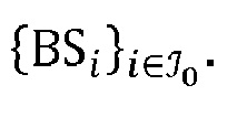
-
Figure 10 shows further possible implementations of theblock 809 offigure 8 for the case that no information from the neighboring base stations
figure 10 ), theapparatus 301 checks whether the condition defined by equation (5) is met (block 1003 offigure 10 ). Inblock 1005a or alternatively block 1005b offigure 10 the dimension of the subspace spanned by the aggregate interfering channel G (n) is reduced by resorting to its singular value decomposition. Then, G (n + 1) results from removing the weakest interfering directions from G (n) and/or the interfering directions in G (n) that are the most aligned to the DL channel H (blocks figure 10 ). - Thus, in an embodiment the
modifier 305 is configured to modify the aggregate interference channel G to obtain the modified aggregate interference channel F by determining a singular value decomposition of the aggregate interference channel G of the form G = UΛVH comprising a diagonal matrix Λ, modifying, e.g. reducing, at least one of the singular values of the diagonal matrix Λ to obtain a modified diagonal matrix Λ*, and by determining the modified aggregate interference channel F as F = UΛ∗ VH . -
Figure 11 shows further possible implementations of theblock 809 offigure 8 for the case that at least one, preferably several neighboring base station(s) BS i , provides to the base station BS0 information in the form of a set(s)identifying the antenna elements of the neighboring base station(s) BS i , whose interference should be cancelled. Assuming that the sets
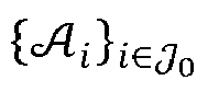
apparatus 301 implemented as a component of the base station BS0 can calculate the initial ordered interference-free antenna set(0) including all elements of
 (n) denote the ordered interference-free antenna set, given that the interference created through G (n) is cancelled. Given the channel H and the current aggregated interfering channel G (n) as inputs (block 1101 of
figure 11 ), theapparatus 301 checks whether the condition defined by equation (5) is met (block 1103 offigure 11 ). Then, G (n + 1) is obtained by removing from G (n) the row corresponding to the T 0 × 1 channel connecting the T 0 transmit antennas of the base station BS0 to the ai -th antenna element of the neighboring base station BS i , with ai being the first element in(n) (blocks figure 11 ). The interference-free antenna set is updated as
blocks figure 11 ). - Embodiments of the invention provide, in particular, for the following advantages. Embodiments of the invention allow dealing with the following two types of interference which result from full-duplex operation: (i) inter-cell interference between base stations, and (ii) self-interference at a base station. By identifying the interference directions and the downlink user directions, embodiments of the invention are capable of performing interference mitigation while targeting no detrimental effect to the DL users. Embodiments of the invention are flexible in the sense that (i) different types of precoders can be applied, (ii) the input of different kinds of information regarding the interference of the network is possible (e.g. information about preferred interference to be mitigated), and (iii) different kinds of information regarding the interference created in the network can be provided (e.g. information about mitigated interference). The final aggregate interfering channel that is computed by embodiments of the invention can be used by the system scheduler in order to update the set of served downlink users. Moreover, the information about mitigated interference can be used by the schedulers of neighboring full-duplex base stations in order to update their respective sets of served uplink users.
- While a particular feature or aspect of the disclosure may have been disclosed with respect to only one of several implementations or embodiments, such feature or aspect may be combined with one or more other features or aspects of the other implementations or embodiments as may be desired and advantageous for any given or particular application. Furthermore, to the extent that the terms "include", "have", "with", or other variants thereof are used in either the detailed description or the claims, such terms are intended to be inclusive in a manner similar to the term "comprise". Also, the terms "exemplary", "for example" and "e.g." are merely meant as an example, rather than the best or optimal. The terms "coupled" and "connected", along with derivatives may have been used. It should be understood that these terms may have been used to indicate that two elements cooperate or interact with each other regardless whether they are in direct physical or electrical contact, or they are not in direct contact with each other.
- Although specific aspects have been illustrated and described herein, it will be appreciated by those of ordinary skill in the art that a variety of alternate and/or equivalent implementations may be substituted for the specific aspects shown and described without departing from the scope of the present disclosure. This application is intended to cover any adaptations or variations of the specific aspects discussed herein.
- Although the elements in the following claims are recited in a particular sequence with corresponding labeling, unless the claim recitations otherwise imply a particular sequence for implementing some or all of those elements, those elements are not necessarily intended to be limited to being implemented in that particular sequence.
- Many alternatives, modifications, and variations will be apparent to those skilled in the art in light of the above teachings. Of course, those skilled in the art readily recognize that there are numerous applications of the invention beyond those described herein. While the present invention has been described with reference to one or more particular embodiments, those skilled in the art recognize that many changes may be made thereto without departing from the scope of the present invention. It is therefore to be understood that within the scope of the appended claims, the invention may be practiced otherwise than as specifically described herein.
Claims (15)
- An apparatus (301) for managing full-duplex communication between a base station (BS0) and a set of user equipments (101a,b), the base station (BS0) comprising a plurality of transmitter antennas, the plurality of transmitter antennas being associated with a downlink communication channel H between the base station (BS0) and the set of user equipments (101a,b) and a plurality of interference channels G i between the base station (BS0) and a plurality of neighboring base stations (BS i ), the apparatus (301) comprising:a determiner (303) configured to determine an aggregate interference channel G on the basis of the plurality of interference channels G i ;a modifier (305) configured to modify the aggregate interference channel G to obtain a modified aggregate interference channel F under the constraint that a performance measure depending on the downlink communication channel H and the modified aggregate interference channel F meets a performance measure criterion, wherein the modified aggregate interference channel F spans a subspace of the space spanned by the aggregate interference channel G ; anda precoder (307) configured to precode signals to be transmitted by the plurality of transmitter antennas on the basis of a precoder matrix W , wherein the precoder matrix W depends on the modified aggregate interference channel F .
- The apparatus (301) of claim 1, wherein the determiner (303) is configured to determine the aggregate interference channel G on the basis of the plurality of interference channels G i and a self-interference channel G 0 between the plurality of transmitter antennas and a plurality of receiver antennas of the base station (BS0).
- The apparatus (301) of claims 1 or 2, wherein the modifier (305) is configured to modify the aggregate interference channel G to obtain the modified aggregate interference channel F under the constraint that a performance measure depending on the downlink communication channel H and the modified aggregate interference channel F meets a performance measure criterion by removing at least one column or row of the aggregate interference channel G that is the most aligned to the space spanned by the downlink communication channel H .
- The apparatus (301) of any one of the preceding claims, wherein the precoder (307) is a regularized zero-forcing precoder (307), wherein the zero-forcing precoder (307) is configured to adjust the degree of orthogonality to the space spanned by the modified aggregate interference channel F on the basis of a parameter associated with noise and/or interference level.
- The apparatus (301) of any one of the preceding claims, wherein the precoder matrix W depends on the modified aggregate interference channel F in such a way that the space spanned by the precoder matrix W is orthogonal to the space spanned by the modified aggregate interference channel F .
- The apparatus (301) of any one of the preceding claims, wherein the performance measure criterion comprises a performance measure criterion for each user equipment of the set of user equipments (101a,b), wherein each performance measure criterion is defined by the following equation:

- The apparatus (301) of any one of the preceding claims, wherein the modifier (305) is configured to modify the aggregate interference channel G to obtain the modified aggregate interference channel F by determining a singular value decomposition of the aggregate interference channel G of the form G = UΛVH comprising a diagonal matrix Λ, modifying at least one of the singular values of the diagonal matrix Λ to obtain a modified diagonal matrix Λ*, and by determining the modified aggregate interference channel F as F = UΛ∗ VH .
- The apparatus (301) of any one of the preceding claims, wherein the modifier (305) is configured to modify the aggregate interference channel G to obtain a modified aggregate interference channel F on the basis of information provided by at least one neighboring base station of the plurality of neighboring base stations (BS i ).
- The apparatus (301) of claim 8, wherein the information provided by the at least one neighboring base station of the plurality of neighboring base stations (BS i ) comprises information identifying at least one receiver antenna of the at least one neighboring base station of the plurality of neighboring base stations (BS i ) for which interference should be mitigated.
- The apparatus (301) of claim 9, wherein the modifier (305) is configured to modify the aggregate interference channel G to obtain the modified aggregate interference channel F by removing a row or column of the aggregate interference channel G associated with the identified receiver antenna of the at least one neighboring base station of the plurality of neighboring base stations (BS i ) for which interference should be mitigated.
- The apparatus (301) of any one of the preceding claims, wherein the apparatus (301) further comprises a scheduler (309) configured to adjust the set of user equipments (101a,b) served by the base station (BS0) on the basis of the modified aggregate interference channel F and/or the precoder matrix W .
- The apparatus (301) of any one of the preceding claims, wherein the apparatus (301) is configured to provide information about the modified aggregate interference channel F to at least one neighboring base station of the plurality of neighboring base stations (BS i ).
- A base station (BS0) comprising the apparatus (301) of any one of the preceding claims.
- A method (400) for managing full-duplex communication between a base station (BS0) and a set of user equipments (101a,b), the base station (BS0) comprising a plurality of transmitter antennas, the plurality of transmitter antennas being associated with a downlink communication channel H between the base station (BS0) and the set of user equipments (101a,b) and a plurality of interference channels G i between the base station (BS0) and a plurality of neighboring base stations (BS i ), the method (400) comprising:determining (401) an aggregate interference channel G on the basis of the plurality of interference channels G i ;modifying (403) the aggregate interference channel G to obtain a modified aggregate interference channel F under the constraint that a performance measure depending on the downlink communication channel H and the modified aggregate interference channel F meets a performance measure criterion, wherein the modified aggregate interference channel F spans a subspace of the space spanned by the aggregate interference channel G ; andprecoding (405) signals to be transmitted by the plurality of transmitter antennas on the basis of a precoder matrix W , wherein the precoder matrix W depends on the modified aggregate interference channel F .
- A computer program comprising program code for performing the method (400) of claim 14 when executed on a computer.
Applications Claiming Priority (1)
| Application Number | Priority Date | Filing Date | Title |
|---|---|---|---|
| PCT/EP2016/051504 WO2017129227A1 (en) | 2016-01-26 | 2016-01-26 | An apparatus and a method for managing full-duplex communication between a base station and a plurality of user equipments |
Publications (2)
| Publication Number | Publication Date |
|---|---|
| EP3403364A1 EP3403364A1 (en) | 2018-11-21 |
| EP3403364B1 true EP3403364B1 (en) | 2019-10-02 |
Family
ID=55237640
Family Applications (1)
| Application Number | Title | Priority Date | Filing Date |
|---|---|---|---|
| EP16701746.6A Active EP3403364B1 (en) | 2016-01-26 | 2016-01-26 | An apparatus and a method for managing full-duplex communication between a base station and a plurality of user equipments |
Country Status (4)
| Country | Link |
|---|---|
| US (1) | US10715303B2 (en) |
| EP (1) | EP3403364B1 (en) |
| CN (1) | CN108604978B (en) |
| WO (1) | WO2017129227A1 (en) |
Families Citing this family (7)
| Publication number | Priority date | Publication date | Assignee | Title |
|---|---|---|---|---|
| EP3203648B1 (en) * | 2016-02-04 | 2018-08-15 | Mitsubishi Electric R&D Centre Europe B.V. | Method for determining parameters for configuring a regularized zero-forcing precoder |
| US11838069B2 (en) | 2018-01-08 | 2023-12-05 | British Telecommunications Public Limited Company | Method and apparatus for transmitting data in a communication system |
| US10784910B1 (en) * | 2018-09-28 | 2020-09-22 | Perspecta Labs Inc. | Multi-antenna jamming/interference protection for waveforms |
| US12556354B2 (en) * | 2020-09-17 | 2026-02-17 | Qualcomm Incorporated | Timing event trigger full duplex abortion |
| GB2601566A (en) * | 2020-12-07 | 2022-06-08 | British Telecomm | Improvements to MIMO systems |
| US20240204976A1 (en) * | 2022-12-20 | 2024-06-20 | Qualcomm Incorporated | Fractional band self-interference cancellation for full-duplex communications |
| US20240430135A1 (en) * | 2023-06-22 | 2024-12-26 | Qualcomm Incorporated | Interference reduction |
Family Cites Families (14)
| Publication number | Priority date | Publication date | Assignee | Title |
|---|---|---|---|---|
| JP4536780B2 (en) * | 2004-11-05 | 2010-09-01 | 株式会社エヌ・ティ・ティ・ドコモ | Multi-user transmission system |
| US8559359B2 (en) * | 2008-04-29 | 2013-10-15 | Qualcomm Incorporated | Information exchange mechanisms to achieve network QoS in wireless cellular systems |
| KR101486378B1 (en) * | 2008-05-07 | 2015-01-26 | 엘지전자 주식회사 | Methods of transmitting and receciving data in collative multiple input multiple output antenna mobile communication system |
| CN101882965A (en) * | 2010-06-11 | 2010-11-10 | 北京交通大学 | A kind of anti-interference full-duplex relay communication system and full-duplex relay equipment |
| JP2014502064A (en) * | 2010-12-27 | 2014-01-23 | 日本電気株式会社 | Base station and feedback information control method in wireless communication system |
| KR20130117413A (en) * | 2012-04-17 | 2013-10-28 | 한국전자통신연구원 | Method and apparatus for coordinating intercell interference |
| EP2945447A4 (en) | 2013-01-09 | 2016-08-03 | Sharp Kk | Terminal device and base station device |
| US10560244B2 (en) * | 2013-07-24 | 2020-02-11 | At&T Intellectual Property I, L.P. | System and method for reducing inter-cellsite interference in full-duplex communications |
| US9456360B2 (en) * | 2013-08-06 | 2016-09-27 | Universitat Politecnica De Catalunya | Method and systems for decentralized interference management in a multi-antenna wireless communication system |
| CN104735789B (en) * | 2013-12-19 | 2018-06-26 | 中国移动通信集团公司 | A kind of inter-cell interference cancellation method, apparatus and system |
| EP4307601A3 (en) * | 2014-03-06 | 2024-08-14 | InterDigital Patent Holdings, Inc. | Full duplex operation in wireless systems |
| CN105306174B (en) * | 2014-06-20 | 2020-01-14 | 中兴通讯股份有限公司 | Method and device for realizing interference alignment based on codebook design and selection |
| CN105007248B (en) * | 2015-08-25 | 2018-05-18 | 成都东讯电子技术有限公司 | A kind of downlink precoding method of MIMO Full-duplex cellular systems |
| GB2546316B (en) * | 2016-01-15 | 2018-10-24 | Samsung Electronics Co Ltd | Improvements in and relating to interference management |
-
2016
- 2016-01-26 EP EP16701746.6A patent/EP3403364B1/en active Active
- 2016-01-26 CN CN201680080274.3A patent/CN108604978B/en active Active
- 2016-01-26 WO PCT/EP2016/051504 patent/WO2017129227A1/en not_active Ceased
-
2018
- 2018-07-25 US US16/045,340 patent/US10715303B2/en active Active
Non-Patent Citations (1)
| Title |
|---|
| None * |
Also Published As
| Publication number | Publication date |
|---|---|
| US10715303B2 (en) | 2020-07-14 |
| CN108604978B (en) | 2020-09-08 |
| WO2017129227A1 (en) | 2017-08-03 |
| CN108604978A (en) | 2018-09-28 |
| US20180359076A1 (en) | 2018-12-13 |
| EP3403364A1 (en) | 2018-11-21 |
Similar Documents
| Publication | Publication Date | Title |
|---|---|---|
| Bansal et al. | Rate-splitting multiple access for intelligent reflecting surface aided multi-user communications | |
| US10715303B2 (en) | Apparatus and a method for managing full-duplex communication between a base station and a plurality of user equipments | |
| EP3949141B1 (en) | Massive cooperative multipoint network operation | |
| Van Chien et al. | Joint pilot design and uplink power allocation in multi-cell massive MIMO systems | |
| RU2663829C2 (en) | Exploiting inter-cell multiplexing gain in wireless cellular systems | |
| RU2674755C2 (en) | Systems and methods for radio freguency calibration using principle of reciprocity of channels in wireless communication systems with distributed input-distributed output | |
| Flores et al. | Clustered cell-free multi-user multiple-antenna systems with rate-splitting: Precoder design and power allocation | |
| Jang et al. | CoMP-CSB for ICI nulling with user selection | |
| US20120120884A1 (en) | Wireless communication apparatus, wireless communication system, and wireless communication method | |
| Li et al. | Optimizing channel-statistics-based analog beamforming for millimeter-wave multi-user massive MIMO downlink | |
| Lee et al. | Transceiver design based on interference alignment in MIMO interfering broadcast channels | |
| Moghadam et al. | Pilot precoding and combining in multiuser MIMO networks | |
| Sultan et al. | Joint transmitter-receiver optimization and self-interference suppression in full-duplex MIMO systems | |
| Prashar et al. | Performance analysis of mimo-noma and siso-noma in downlink communication systems | |
| WO2015119461A1 (en) | Method and device for transmitting signal in wireless communication system | |
| Kim et al. | Limited feedback for multicell zero-forcing coordinated beamforming in time-varying channels | |
| Galappaththige et al. | Cell-free full-duplex communication–An overview | |
| Badr et al. | A novel vision to mitigate pilot contamination in massive MIMO-based 5G networks | |
| Ali et al. | Spectral efficiency enhancement in Massive MIMO system under pilot contamination | |
| Bogale et al. | Pilot contamination mitigation for wideband massive MIMO systems | |
| Fritzsche et al. | Distributed robust sum rate maximization in cooperative cellular networks | |
| Kim et al. | Coordinated beamforming, interference-aware power control, and scheduling framework for 6G wireless networks | |
| Behjati et al. | What is the value of limited feedback for next generation of cellular systems? | |
| García Armada et al. | Constrained power allocation schemes for coordinated base station transmission using block diagonalization | |
| Alimo et al. | Coverage, throughput, and energy efficiency enhancement in beamspace massive MIMO system using rate-splitting and orthogonal precoding |
Legal Events
| Date | Code | Title | Description |
|---|---|---|---|
| STAA | Information on the status of an ep patent application or granted ep patent |
Free format text: STATUS: THE INTERNATIONAL PUBLICATION HAS BEEN MADE |
|
| PUAI | Public reference made under article 153(3) epc to a published international application that has entered the european phase |
Free format text: ORIGINAL CODE: 0009012 |
|
| STAA | Information on the status of an ep patent application or granted ep patent |
Free format text: STATUS: REQUEST FOR EXAMINATION WAS MADE |
|
| 17P | Request for examination filed |
Effective date: 20180813 |
|
| AK | Designated contracting states |
Kind code of ref document: A1 Designated state(s): AL AT BE BG CH CY CZ DE DK EE ES FI FR GB GR HR HU IE IS IT LI LT LU LV MC MK MT NL NO PL PT RO RS SE SI SK SM TR |
|
| AX | Request for extension of the european patent |
Extension state: BA ME |
|
| GRAP | Despatch of communication of intention to grant a patent |
Free format text: ORIGINAL CODE: EPIDOSNIGR1 |
|
| STAA | Information on the status of an ep patent application or granted ep patent |
Free format text: STATUS: GRANT OF PATENT IS INTENDED |
|
| DAV | Request for validation of the european patent (deleted) | ||
| DAX | Request for extension of the european patent (deleted) | ||
| INTG | Intention to grant announced |
Effective date: 20190426 |
|
| GRAS | Grant fee paid |
Free format text: ORIGINAL CODE: EPIDOSNIGR3 |
|
| GRAA | (expected) grant |
Free format text: ORIGINAL CODE: 0009210 |
|
| STAA | Information on the status of an ep patent application or granted ep patent |
Free format text: STATUS: THE PATENT HAS BEEN GRANTED |
|
| AK | Designated contracting states |
Kind code of ref document: B1 Designated state(s): AL AT BE BG CH CY CZ DE DK EE ES FI FR GB GR HR HU IE IS IT LI LT LU LV MC MK MT NL NO PL PT RO RS SE SI SK SM TR |
|
| REG | Reference to a national code |
Ref country code: GB Ref legal event code: FG4D |
|
| REG | Reference to a national code |
Ref country code: CH Ref legal event code: EP Ref country code: AT Ref legal event code: REF Ref document number: 1187403 Country of ref document: AT Kind code of ref document: T Effective date: 20191015 |
|
| REG | Reference to a national code |
Ref country code: DE Ref legal event code: R096 Ref document number: 602016021619 Country of ref document: DE |
|
| REG | Reference to a national code |
Ref country code: IE Ref legal event code: FG4D |
|
| REG | Reference to a national code |
Ref country code: NL Ref legal event code: MP Effective date: 20191002 |
|
| REG | Reference to a national code |
Ref country code: LT Ref legal event code: MG4D |
|
| REG | Reference to a national code |
Ref country code: AT Ref legal event code: MK05 Ref document number: 1187403 Country of ref document: AT Kind code of ref document: T Effective date: 20191002 |
|
| PG25 | Lapsed in a contracting state [announced via postgrant information from national office to epo] |
Ref country code: FI Free format text: LAPSE BECAUSE OF FAILURE TO SUBMIT A TRANSLATION OF THE DESCRIPTION OR TO PAY THE FEE WITHIN THE PRESCRIBED TIME-LIMIT Effective date: 20191002 Ref country code: BG Free format text: LAPSE BECAUSE OF FAILURE TO SUBMIT A TRANSLATION OF THE DESCRIPTION OR TO PAY THE FEE WITHIN THE PRESCRIBED TIME-LIMIT Effective date: 20200102 Ref country code: PT Free format text: LAPSE BECAUSE OF FAILURE TO SUBMIT A TRANSLATION OF THE DESCRIPTION OR TO PAY THE FEE WITHIN THE PRESCRIBED TIME-LIMIT Effective date: 20200203 Ref country code: LV Free format text: LAPSE BECAUSE OF FAILURE TO SUBMIT A TRANSLATION OF THE DESCRIPTION OR TO PAY THE FEE WITHIN THE PRESCRIBED TIME-LIMIT Effective date: 20191002 Ref country code: AT Free format text: LAPSE BECAUSE OF FAILURE TO SUBMIT A TRANSLATION OF THE DESCRIPTION OR TO PAY THE FEE WITHIN THE PRESCRIBED TIME-LIMIT Effective date: 20191002 Ref country code: SE Free format text: LAPSE BECAUSE OF FAILURE TO SUBMIT A TRANSLATION OF THE DESCRIPTION OR TO PAY THE FEE WITHIN THE PRESCRIBED TIME-LIMIT Effective date: 20191002 Ref country code: NL Free format text: LAPSE BECAUSE OF FAILURE TO SUBMIT A TRANSLATION OF THE DESCRIPTION OR TO PAY THE FEE WITHIN THE PRESCRIBED TIME-LIMIT Effective date: 20191002 Ref country code: ES Free format text: LAPSE BECAUSE OF FAILURE TO SUBMIT A TRANSLATION OF THE DESCRIPTION OR TO PAY THE FEE WITHIN THE PRESCRIBED TIME-LIMIT Effective date: 20191002 Ref country code: LT Free format text: LAPSE BECAUSE OF FAILURE TO SUBMIT A TRANSLATION OF THE DESCRIPTION OR TO PAY THE FEE WITHIN THE PRESCRIBED TIME-LIMIT Effective date: 20191002 Ref country code: GR Free format text: LAPSE BECAUSE OF FAILURE TO SUBMIT A TRANSLATION OF THE DESCRIPTION OR TO PAY THE FEE WITHIN THE PRESCRIBED TIME-LIMIT Effective date: 20200103 Ref country code: NO Free format text: LAPSE BECAUSE OF FAILURE TO SUBMIT A TRANSLATION OF THE DESCRIPTION OR TO PAY THE FEE WITHIN THE PRESCRIBED TIME-LIMIT Effective date: 20200102 Ref country code: PL Free format text: LAPSE BECAUSE OF FAILURE TO SUBMIT A TRANSLATION OF THE DESCRIPTION OR TO PAY THE FEE WITHIN THE PRESCRIBED TIME-LIMIT Effective date: 20191002 |
|
| PG25 | Lapsed in a contracting state [announced via postgrant information from national office to epo] |
Ref country code: HR Free format text: LAPSE BECAUSE OF FAILURE TO SUBMIT A TRANSLATION OF THE DESCRIPTION OR TO PAY THE FEE WITHIN THE PRESCRIBED TIME-LIMIT Effective date: 20191002 Ref country code: RS Free format text: LAPSE BECAUSE OF FAILURE TO SUBMIT A TRANSLATION OF THE DESCRIPTION OR TO PAY THE FEE WITHIN THE PRESCRIBED TIME-LIMIT Effective date: 20191002 Ref country code: IS Free format text: LAPSE BECAUSE OF FAILURE TO SUBMIT A TRANSLATION OF THE DESCRIPTION OR TO PAY THE FEE WITHIN THE PRESCRIBED TIME-LIMIT Effective date: 20200224 Ref country code: CZ Free format text: LAPSE BECAUSE OF FAILURE TO SUBMIT A TRANSLATION OF THE DESCRIPTION OR TO PAY THE FEE WITHIN THE PRESCRIBED TIME-LIMIT Effective date: 20191002 |
|
| PG25 | Lapsed in a contracting state [announced via postgrant information from national office to epo] |
Ref country code: AL Free format text: LAPSE BECAUSE OF FAILURE TO SUBMIT A TRANSLATION OF THE DESCRIPTION OR TO PAY THE FEE WITHIN THE PRESCRIBED TIME-LIMIT Effective date: 20191002 |
|
| REG | Reference to a national code |
Ref country code: DE Ref legal event code: R097 Ref document number: 602016021619 Country of ref document: DE |
|
| PG2D | Information on lapse in contracting state deleted |
Ref country code: IS |
|
| PG25 | Lapsed in a contracting state [announced via postgrant information from national office to epo] |
Ref country code: DK Free format text: LAPSE BECAUSE OF FAILURE TO SUBMIT A TRANSLATION OF THE DESCRIPTION OR TO PAY THE FEE WITHIN THE PRESCRIBED TIME-LIMIT Effective date: 20191002 Ref country code: RO Free format text: LAPSE BECAUSE OF FAILURE TO SUBMIT A TRANSLATION OF THE DESCRIPTION OR TO PAY THE FEE WITHIN THE PRESCRIBED TIME-LIMIT Effective date: 20191002 Ref country code: EE Free format text: LAPSE BECAUSE OF FAILURE TO SUBMIT A TRANSLATION OF THE DESCRIPTION OR TO PAY THE FEE WITHIN THE PRESCRIBED TIME-LIMIT Effective date: 20191002 Ref country code: IS Free format text: LAPSE BECAUSE OF FAILURE TO SUBMIT A TRANSLATION OF THE DESCRIPTION OR TO PAY THE FEE WITHIN THE PRESCRIBED TIME-LIMIT Effective date: 20200202 |
|
| REG | Reference to a national code |
Ref country code: DE Ref legal event code: R119 Ref document number: 602016021619 Country of ref document: DE |
|
| PLBE | No opposition filed within time limit |
Free format text: ORIGINAL CODE: 0009261 |
|
| STAA | Information on the status of an ep patent application or granted ep patent |
Free format text: STATUS: NO OPPOSITION FILED WITHIN TIME LIMIT |
|
| PG25 | Lapsed in a contracting state [announced via postgrant information from national office to epo] |
Ref country code: MC Free format text: LAPSE BECAUSE OF FAILURE TO SUBMIT A TRANSLATION OF THE DESCRIPTION OR TO PAY THE FEE WITHIN THE PRESCRIBED TIME-LIMIT Effective date: 20191002 Ref country code: SK Free format text: LAPSE BECAUSE OF FAILURE TO SUBMIT A TRANSLATION OF THE DESCRIPTION OR TO PAY THE FEE WITHIN THE PRESCRIBED TIME-LIMIT Effective date: 20191002 Ref country code: IT Free format text: LAPSE BECAUSE OF FAILURE TO SUBMIT A TRANSLATION OF THE DESCRIPTION OR TO PAY THE FEE WITHIN THE PRESCRIBED TIME-LIMIT Effective date: 20191002 Ref country code: SM Free format text: LAPSE BECAUSE OF FAILURE TO SUBMIT A TRANSLATION OF THE DESCRIPTION OR TO PAY THE FEE WITHIN THE PRESCRIBED TIME-LIMIT Effective date: 20191002 |
|
| REG | Reference to a national code |
Ref country code: CH Ref legal event code: PL |
|
| 26N | No opposition filed |
Effective date: 20200703 |
|
| REG | Reference to a national code |
Ref country code: BE Ref legal event code: MM Effective date: 20200131 |
|
| PG25 | Lapsed in a contracting state [announced via postgrant information from national office to epo] |
Ref country code: DE Free format text: LAPSE BECAUSE OF NON-PAYMENT OF DUE FEES Effective date: 20200801 Ref country code: LU Free format text: LAPSE BECAUSE OF NON-PAYMENT OF DUE FEES Effective date: 20200126 |
|
| PG25 | Lapsed in a contracting state [announced via postgrant information from national office to epo] |
Ref country code: BE Free format text: LAPSE BECAUSE OF NON-PAYMENT OF DUE FEES Effective date: 20200131 Ref country code: CH Free format text: LAPSE BECAUSE OF NON-PAYMENT OF DUE FEES Effective date: 20200131 Ref country code: SI Free format text: LAPSE BECAUSE OF FAILURE TO SUBMIT A TRANSLATION OF THE DESCRIPTION OR TO PAY THE FEE WITHIN THE PRESCRIBED TIME-LIMIT Effective date: 20191002 Ref country code: LI Free format text: LAPSE BECAUSE OF NON-PAYMENT OF DUE FEES Effective date: 20200131 |
|
| PG25 | Lapsed in a contracting state [announced via postgrant information from national office to epo] |
Ref country code: IE Free format text: LAPSE BECAUSE OF NON-PAYMENT OF DUE FEES Effective date: 20200126 |
|
| PG25 | Lapsed in a contracting state [announced via postgrant information from national office to epo] |
Ref country code: TR Free format text: LAPSE BECAUSE OF FAILURE TO SUBMIT A TRANSLATION OF THE DESCRIPTION OR TO PAY THE FEE WITHIN THE PRESCRIBED TIME-LIMIT Effective date: 20191002 Ref country code: MT Free format text: LAPSE BECAUSE OF FAILURE TO SUBMIT A TRANSLATION OF THE DESCRIPTION OR TO PAY THE FEE WITHIN THE PRESCRIBED TIME-LIMIT Effective date: 20191002 Ref country code: CY Free format text: LAPSE BECAUSE OF FAILURE TO SUBMIT A TRANSLATION OF THE DESCRIPTION OR TO PAY THE FEE WITHIN THE PRESCRIBED TIME-LIMIT Effective date: 20191002 |
|
| PG25 | Lapsed in a contracting state [announced via postgrant information from national office to epo] |
Ref country code: MK Free format text: LAPSE BECAUSE OF FAILURE TO SUBMIT A TRANSLATION OF THE DESCRIPTION OR TO PAY THE FEE WITHIN THE PRESCRIBED TIME-LIMIT Effective date: 20191002 |
|
| PGFP | Annual fee paid to national office [announced via postgrant information from national office to epo] |
Ref country code: GB Payment date: 20251204 Year of fee payment: 11 |
|
| PGFP | Annual fee paid to national office [announced via postgrant information from national office to epo] |
Ref country code: FR Payment date: 20251208 Year of fee payment: 11 |