EP3403126B1 - Systems and methods for instant total internal reflection fluorescence/structured illumination microscopy - Google Patents
Systems and methods for instant total internal reflection fluorescence/structured illumination microscopy Download PDFInfo
- Publication number
- EP3403126B1 EP3403126B1 EP17844356.0A EP17844356A EP3403126B1 EP 3403126 B1 EP3403126 B1 EP 3403126B1 EP 17844356 A EP17844356 A EP 17844356A EP 3403126 B1 EP3403126 B1 EP 3403126B1
- Authority
- EP
- European Patent Office
- Prior art keywords
- lens
- angle
- excitation
- sample
- array
- Prior art date
- Legal status (The legal status is an assumption and is not a legal conclusion. Google has not performed a legal analysis and makes no representation as to the accuracy of the status listed.)
- Active
Links
Images








Classifications
-
- G—PHYSICS
- G02—OPTICS
- G02B—OPTICAL ELEMENTS, SYSTEMS OR APPARATUS
- G02B21/00—Microscopes
- G02B21/16—Microscopes adapted for ultraviolet illumination ; Fluorescence microscopes
-
- G—PHYSICS
- G01—MEASURING; TESTING
- G01N—INVESTIGATING OR ANALYSING MATERIALS BY DETERMINING THEIR CHEMICAL OR PHYSICAL PROPERTIES
- G01N21/00—Investigating or analysing materials by the use of optical means, i.e. using sub-millimetre waves, infrared, visible or ultraviolet light
- G01N21/62—Systems in which the material investigated is excited whereby it emits light or causes a change in wavelength of the incident light
- G01N21/63—Systems in which the material investigated is excited whereby it emits light or causes a change in wavelength of the incident light optically excited
- G01N21/64—Fluorescence; Phosphorescence
- G01N21/645—Specially adapted constructive features of fluorimeters
- G01N21/6456—Spatial resolved fluorescence measurements; Imaging
- G01N21/6458—Fluorescence microscopy
-
- G—PHYSICS
- G01—MEASURING; TESTING
- G01N—INVESTIGATING OR ANALYSING MATERIALS BY DETERMINING THEIR CHEMICAL OR PHYSICAL PROPERTIES
- G01N21/00—Investigating or analysing materials by the use of optical means, i.e. using sub-millimetre waves, infrared, visible or ultraviolet light
- G01N21/62—Systems in which the material investigated is excited whereby it emits light or causes a change in wavelength of the incident light
- G01N21/63—Systems in which the material investigated is excited whereby it emits light or causes a change in wavelength of the incident light optically excited
- G01N21/64—Fluorescence; Phosphorescence
- G01N21/645—Specially adapted constructive features of fluorimeters
- G01N21/648—Specially adapted constructive features of fluorimeters using evanescent coupling or surface plasmon coupling for the excitation of fluorescence
-
- G—PHYSICS
- G02—OPTICS
- G02B—OPTICAL ELEMENTS, SYSTEMS OR APPARATUS
- G02B21/00—Microscopes
- G02B21/0004—Microscopes specially adapted for specific applications
- G02B21/002—Scanning microscopes
- G02B21/0024—Confocal scanning microscopes (CSOMs) or confocal "macroscopes"; Accessories which are not restricted to use with CSOMs, e.g. sample holders
- G02B21/0032—Optical details of illumination, e.g. light-sources, pinholes, beam splitters, slits, fibers
-
- G—PHYSICS
- G02—OPTICS
- G02B—OPTICAL ELEMENTS, SYSTEMS OR APPARATUS
- G02B21/00—Microscopes
- G02B21/0004—Microscopes specially adapted for specific applications
- G02B21/002—Scanning microscopes
- G02B21/0024—Confocal scanning microscopes (CSOMs) or confocal "macroscopes"; Accessories which are not restricted to use with CSOMs, e.g. sample holders
- G02B21/0036—Scanning details, e.g. scanning stages
- G02B21/0044—Scanning details, e.g. scanning stages moving apertures, e.g. Nipkow disks, rotating lens arrays
-
- G—PHYSICS
- G02—OPTICS
- G02B—OPTICAL ELEMENTS, SYSTEMS OR APPARATUS
- G02B21/00—Microscopes
- G02B21/0004—Microscopes specially adapted for specific applications
- G02B21/002—Scanning microscopes
- G02B21/0024—Confocal scanning microscopes (CSOMs) or confocal "macroscopes"; Accessories which are not restricted to use with CSOMs, e.g. sample holders
- G02B21/0052—Optical details of the image generation
- G02B21/0076—Optical details of the image generation arrangements using fluorescence or luminescence
-
- G—PHYSICS
- G02—OPTICS
- G02B—OPTICAL ELEMENTS, SYSTEMS OR APPARATUS
- G02B21/00—Microscopes
- G02B21/36—Microscopes arranged for photographic purposes or projection purposes or digital imaging or video purposes including associated control and data processing arrangements
-
- G—PHYSICS
- G02—OPTICS
- G02B—OPTICAL ELEMENTS, SYSTEMS OR APPARATUS
- G02B27/00—Optical systems or apparatus not provided for by any of the groups G02B1/00 - G02B26/00, G02B30/00
- G02B27/58—Optics for apodization or superresolution; Optical synthetic aperture systems
-
- G—PHYSICS
- G01—MEASURING; TESTING
- G01N—INVESTIGATING OR ANALYSING MATERIALS BY DETERMINING THEIR CHEMICAL OR PHYSICAL PROPERTIES
- G01N21/00—Investigating or analysing materials by the use of optical means, i.e. using sub-millimetre waves, infrared, visible or ultraviolet light
- G01N21/62—Systems in which the material investigated is excited whereby it emits light or causes a change in wavelength of the incident light
- G01N21/63—Systems in which the material investigated is excited whereby it emits light or causes a change in wavelength of the incident light optically excited
- G01N21/64—Fluorescence; Phosphorescence
- G01N21/645—Specially adapted constructive features of fluorimeters
- G01N2021/6463—Optics
-
- G—PHYSICS
- G01—MEASURING; TESTING
- G01N—INVESTIGATING OR ANALYSING MATERIALS BY DETERMINING THEIR CHEMICAL OR PHYSICAL PROPERTIES
- G01N2201/00—Features of devices classified in G01N21/00
- G01N2201/10—Scanning
- G01N2201/105—Purely optical scan
-
- G—PHYSICS
- G02—OPTICS
- G02B—OPTICAL ELEMENTS, SYSTEMS OR APPARATUS
- G02B21/00—Microscopes
- G02B21/0004—Microscopes specially adapted for specific applications
- G02B21/002—Scanning microscopes
- G02B21/0024—Confocal scanning microscopes (CSOMs) or confocal "macroscopes"; Accessories which are not restricted to use with CSOMs, e.g. sample holders
- G02B21/0036—Scanning details, e.g. scanning stages
- G02B21/0048—Scanning details, e.g. scanning stages scanning mirrors, e.g. rotating or galvanomirrors, MEMS mirrors
Definitions
- the present disclosure generally relates to instant structured illumination microscopy (SIM) and in particular to systems and methods for instant structured illumination microscopy where total internal reflection fluorescence (TIRF) techniques may be used to improve optical sectioning and signal-to-noise ratio.
- SIM instant structured illumination microscopy
- TIRF total internal reflection fluorescence
- n 1 sin(theta1) n 2 sin(theta2), where theta1 is the angle of incoming light (measured from the surface normal) and theta2 is the corresponding outgoing angle for the refracted light.
- theta2 pi/2
- theta1 arcsin(n 2 /n 1 ) is the "critical angle”. Any light ray at or exceeding the critical angle is "totally internally reflected", and no light propagates past the interface into the far field on the lower index side of the boundary.
- an evanescent wave exists at the interface of the boundary and can excite fluorescent molecules within lambda (the wavelength of excitation) distance from the boundary, on the n 2 side.
- This evanescent wave is used in TIRF to generate very high contrast, high signal-to-noise ratio images of fluorescently-labeled samples, such as the cell membrane, at or near the coverslip boundary.
- a convenient method of setting up TIRF conditions is to use a high numerical aperture objective (typically 1.4 NA or higher, so that aqueous samples with n2 ⁇ 1.33, the refractive index of a cell may be imaged) and ensure that only marginal rays pass through the back focal plane of the objective lens.
- a high numerical aperture objective typically 1.4 NA or higher, so that aqueous samples with n2 ⁇ 1.33, the refractive index of a cell may be imaged
- Such "objective side TIRF” has been very successful in cell biology applications, where it has been used for decades.
- SIM Structured illumination microscopy
- US2016238827A1 discloses a multi-focal selective illumination microscopy (SIM) system for generating multi-focal patterns of a sample is disclosed.
- SIM selective illumination microscopy
- the multi-focal SIM system performs a focusing, scaling and summing operation on each multi-focal pattern in a sequence of multi-focal patterns that completely scan the sample to produce a high resolution composite image.
- EP3032312A1 discloses a confocal scanner comprising a first micro lens disk and a second micro lens disk with corresponding microlens arrangement patterns and rotation axis.
- a beam splitter is configured to guide illumination light via the first micro lens disk to an object and further configured to guide a return light from the object having passed through each micro lens of the first micro lens to the corresponding micro lens of the second micro lens disk.
- a numerical aperture of each micro lens arranged on the second micro lens disk is greater than a numerical aperture of each micro lens arranged on the first micro lens disk.
- the instant TIRF/SIM system includes a radial aperture block positioned at a plane conjugate to the back focal plane of the objective lens, thus allowing only high-angle marginal annular light beams from a laser source to excite the sample.
- the radial aperture block of the first embodiment of the instant TIRF/SIM system is replaced with a digital micromirror device (DMD) for varying the evanescent wave to allow ⁇ nm localization of features in the axial direction.
- DMD digital micromirror device
- a spatial light modulator is used to alter the phase of the excitation to optimally induce evanescent, patterned excitation at the sample.
- the radial aperture block is combined with a spinning disk arrangement including a pair of spinning disks having converging microlenses which are arranged with a spinning disk having pinholes to produce contracted non-inverted images of fluorescent foci being emitted by the sample. Combinations of the SLM, DMD, spinning disk arrangement, and an aperture block are also possible.
- Various embodiments of the instant TIRF/SIM system allows for high-speed, super-resolution microscopy at very high signal-to-noise (SNR) ratios for biological applications within -200 nm (e.g., the evanescent wave decay length) distance of a coverslip surface.
- SNR signal-to-noise
- a first embodiment of the instant TIRF/SIM system designated 100 implements a radial aperture block 110 positioned at a plane conjugate to the back focal plane of the objective lens 124 , thus allowing only marginal, annular excitation light beams to pass through for scanning onto a sample 125 as shown in FIG. 1 .
- the instant TIRF/SIM system 100 includes an excitation source 102 , for example a laser component, that generates an excitation beam 104 which is transmitted through a first micro lens array 106.
- the first micro lens array 106 splits the excitation beam 104 into an array of excitation foci 104A.
- a first lens 108 is positioned one focal length away from the focal point of the first micro lens array 106.
- a radial aperture block 110 is positioned at the front focal plane of the first lens 108 to block central rays emerging from the first lens 108, thereby allowing only high-angle, marginal rays 104B emerging from the first lens 108 to pass through the radial aperture block 110.
- An imaging telescope arrangement includes a second lens 112 in line with a third lens 114 that collectively image the marginal rays 104B that pass through the radial aperture block 110.
- the second and third lenses 112 and 114 image the marginal rays 104B to pass through a dichroic mirror 116 and onto a two-sided galvanometric mirror 118.
- the second and third lenses 112 and 114 are separated by the sum of their respective focal lengths.
- the galvanometric mirror 118 redirects and scans the marginal rays 104B through a fourth lens 120 in line with a tube lens 122 and onto the back focal plane of a high numerical aperture objective lens 124.
- This optical arrangement produces a structured illumination that does not propagate into the sample 125, but evanescently excites the sample 125 with the marginal rays 104B being imaged onto the sample 125 by the objective lens 124. Since the marginal rays impinge upon the sample at an angle that exceeds the critical angle they do not propagate into the sample, instead causing only an evanescent wave that decays exponentially within the sample.
- the combination of evanescent (caused by the high angle rays that are created by the radial annular block 110 ), patterned/structured illumination (caused by the micro lens array 106 ) causes very sharp/high contrast excitation at the sample.
- the objective lens 124 may have a numerical aperture > 1.4 NA (i.e. greater than the refractive index of the sample 125 ), such as 1.65 NA or 1.70 NA.
- the resulting excitation 105 generated by the sample 125 scanned by the galvanometer mirror 118 produces a patterned fluorescence emission 105A that may be collected in epi-mode, and then descanned by the galvanometric mirror 118 as the fluorescence emissions 105A are imaged by the arrangement of the objective lens 124, tube lens 122 and fourth lens 120 aligned with the galvanometric mirror 118.
- the fluorescence emissions 105A emitted by the sample 125 are then separated from the resulting excitation 105 via the dichroic mirror 116 that redirects the fluorescence emission 105A.
- a fifth lens 126 is positioned one focal length from the galvanometric mirror 118.
- the fifth lens 126 focuses the descanned fluorescence emission 105A through a second micro lens array 128.
- the second micro lens array 128 has the same pitch/pattern and lens spacing as the first micro lens array 106 such that the fluorescence emissions 105A are locally contracted into contracted fluorescence emissions 105B without inversion or changing the relative distance between adjacent fluorescence emissions 105A as shown in FIGS. 18 and 19 .
- the "contraction factor" depends on the respective wavelengths of the excitation beam 104 and fluorescence emissions 105A and the properties of the radial aperture block 110, and in most cases, may be set at a value of approximately 2.
- a multi-focal pattern 170 for the fluorescence emissions 105A that may be locally contracted into contracted fluorescence emissions 105B is shown in FIGS. 18 and 19 .
- the multi-focal pattern 170 may include a plurality of focal points 172 arranged in a particular multi-focal pattern 170 defined by the plurality of light beams with each multi-focal pattern 170 defining a different arrangement of focal points for the plurality of light beams such that multi-focal pattern 170 maximizes the distance between any two nearest focal points 172 for a given density of focal points 172, thereby minimizing crosstalk.
- crosstalk refers to the ability of nearby light beams to cause excitation and fluorescence from other focal points to appear as if focal points originate from the focal point in question.
- the plurality of light beams in each multi-focal illumination pattern are rastered onto the sample 125 being illuminated such that the sample 125 emits a plurality of fluorescent emissions.
- the fluorescent emissions emitted by the sample 125 are rastered in a de-scanning operation which redirects the plurality of fluorescent emissions for removal of out-of-focus fluorescent emissions in a focusing operation.
- out-of-focus fluorescent emissions are blocked and only in-focus fluorescent emissions are allowed to pass through for processing.
- the in-focus fluorescent emissions caused by each multi-focal pattern are then scaled using a scaling operation that locally contracts each of fluorescent emissions by a predetermined factor.
- a local contraction of the fluorescent foci 172 caused in a single multi-focal pattern 170 occurs.
- the local contraction of fluorescent foci 172A and 172B to scaled fluorescent foci 172A' and 172B', respectively, in the multi-focal pattern 170 is such that the distance 500 between the geometric centers 175 of fluorescent foci 172A and 172B and the distance 502 of fluorescent foci 172A and 172B remains the same regardless of the degree of scaling applied to the fluorescent foci 172 of the multi-focal pattern 170.
- the scaling operation 150 contracts the fluorescent foci 172 locally while keeping the relative distances between each of the fluorescent foci the same.
- a sixth lens 132 is positioned between opposing first and second mirrors 130 and 134.
- the sixth lens 132 is positioned one focal length from the contracted fluorescence emissions 105B and the galvanometer mirror 118 and serves to Fourier-transform the contracted fluorescence emissions 105B onto the galvanometer mirror 118.
- the galvanometer mirror 118 and the seventh lens 138 serve to rescan the contracted fluorescence emissions 105B that forms an image onto a detector component 140, such as a camera, to capture the image.
- an emission filter 136 may be interposed between the second mirror 134 and the galvanometer 118 to remove any residual resulting excitation 105 from the contracted fluorescence emissions 105B.
- the instant TIRF/SIM system 200 substitutes the radial aperture block 110 with a digital micromirror device 210 that varies the evanescent wave to allow ⁇ nm localization of feature in the axial direction.
- the instant TIRF/SIM system 200 includes an excitation source 202, for example a laser component, that generates an excitation beam 204 that is transmitted and passes through a first micro lens array 206.
- the first micro lens array 206 splits the excitation beam 204 into an array of excitation foci 204A.
- a first lens 208 is positioned one focal length away from the focal point of the first micro lens array 206.
- the digital micromirror device 210 may be in communication with the first microlens array 206.
- the digital micromirror device 210 is positioned at the front focal plane of the first lens 208 to block all but the high-angle marginal rays 104B emerging from the first lens 208.
- all of the pixels of the digital micromirror device 210 except those pixels along the periphery of the digital micromirror device 210, are set to reflect the low-angle central rays off axis, thus effectively removing the low-angle central rays from illuminating the sample 225 in a manner similar to the radial block aperture 110.
- the degree of transmitted marginal rays 104B can also be varied, ultimately corresponding to varying the thickness of the evanescent field at the sample 225.
- an imaging telescope arrangement includes a second lens 212 in line with a third lens 214 that collectively image the marginal rays 204B to pass through a dichroic mirror 216 and onto a two-sided galvanometric mirror 218.
- the second and third lenses 212 and 214 are separated by a distance that is the sum of their respective focal lengths.
- the galvanometric mirror 218 redirects and images the marginal rays 204B along third axis 404 through a fourth lens 220 in line with a tube lens 222 and onto the back focal plane of a high numerical aperture objective lens 224.
- the objective lens 224 may have a numerical aperture > 1.4 NA, such as 1.65 NA or 1.70 NA.
- the resulting excitation 205 of the sample 225 produces a patterned fluorescence emission 205A that may be collected in epi-mode, and then descanned by the galvanometric mirror 218 as the fluorescence emissions 205A are imaged by the objective lens 224, tube lens 222 and fourth lens 220 onto the galvanometer mirror 218 .
- the fluorescence emissions 205A are then separated from the resulting excitation 205 via the dichroic mirror 216 that redirects the fluorescence emission 205A.
- a fifth lens 226 is positioned one focal length from the galvanometric mirror 218.
- the fifth lens 226 focuses the descanned fluorescence emission 205A through a second micro lens array 228.
- the second micro lens array 228 has the same pitch/pattern and lens spacing as the first micro lens array 206 such that the fluorescence emissions 205A are locally contracted into contracted fluorescence emissions 205B without inversion or changing the relative distance between adjacent fluorescence emissions 205A.
- a sixth lens 232 is positioned between opposing first and second mirrors 230 and 234, which is in perpendicular relation to the first, third and fourth axes 400, 404 and 406.
- the sixth lens 232 is positioned one focal length from the contracted fluorescence emissions 205B and the galvanometer mirror 218 and serves to Fourier-transform the contracted fluorescence emissions 205B onto the galvanometer mirror 218.
- the galvanometer 218 and the seventh lens 238 serve to rescan the contracted fluorescence emissions 205B that forms an image onto a detector component 240, such as a camera, to capture the image.
- the excitation micro lens array 106 may be replaced by a spatial light modulator 304 or other element that enables the phase of the excitation beam 303 to be manipulated while also generating a patterned illumination at the sample 324.
- a spatial light modulator 304 By generating an appropriate pattern on the spatial light modulator 304, unwanted interference that would otherwise arise due to the interaction of the high angle, annular structured illumination can be minimized.
- the front face of the spatial light modulator 304 is imaged onto the sample 324 as indicated by the optical system illustrated in FIG. 4 . All other optics are the same or similar to the first embodiment of the instant TIRF/SIM system 100 illustrated in FIG. 1 .
- the excitation pattern produced by the spatial light modulator 304 of FIG. 3 is required to have the same pitch as the second microlens array 128 of FIG. 1 .
- a third embodiment of the instant TIRF/SIM system implements a radial aperture block 308 positioned at a plane conjugate to the back focal plane of the objective lens 322, thus allowing only marginal, annular excitation light beams 303B to pass through for scanning onto a sample 324.
- the radial aperture block 308 may be replaced by a digital micromirror device (not shown) and enabling additional functionality (i.e., nm localization in the z direction).
- the instant TIRF/SIM system 300 includes an excitation source 302, for example a laser component, that generates an excitation beam 303 which is transmitted onto a spatial light modulator 304 that splits the excitation beam 303 into an array of excitation foci 303A.
- a first lens 306 is positioned one focal length away from the focal point of the spatial light modulator 304.
- a radial aperture block 308 is positioned at the front focal plane of the first lens 306 to block central rays 303C emerging from the first lens 306, thereby allowing only high-angle, marginal rays 303B emerging from the first lens 306 to pass through the radial aperture block 308.
- An imaging telescope arrangement includes a second lens 310 in line with a third lens 312 that collectively image the high-angle marginal rays 303B that pass through the radial aperture block 308.
- the second and third lenses 310 and 312 image the high-angle marginal rays 303B to pass through a dichroic mirror 314 and onto a two-sided galvanometric mirror 316.
- the second and third lenses 310 and 312 are separated by the sum of their respective focal lengths.
- the galvanometric mirror 316 redirects and scans the high-angle marginal rays 303B through a fourth lens 318 in line with a tube lens 320 and onto the back focal plane of a high numerical aperture objective lens 322.
- This optical arrangement produces a structured illumination that does not propagate into the sample 324, but evanescently excites the sample 324 with the high-angle marginal rays 303B being imaged onto the sample 324 by the objective lens 322. Since the high-angle marginal rays 303B impinge upon the sample 324 at an angle that exceeds the critical angle, the high-angle marginal rays 303B do not propagate into the sample 324, instead causing only an evanescent wave that decays exponentially within the sample 324. The evanescent wave (caused by the high angle, marginal rays 303B that are created by the radial annular block 308) produces very sharp/high contrast excitation at the sample 324.
- the objective lens 322 may have a numerical aperture > 1.4 NA (i.e. greater than the refractive index of the sample), such as 1.65 NA or 1.70 NA.
- the resulting excitation 305 generated by the sample 324 scanned by the galvanometer mirror 316 produces a patterned fluorescence emission 305A that may be collected in epi-mode, and then descanned by the galvanometric mirror 316 as the fluorescence emissions 305A are imaged by the arrangement of the objective lens 322, tube lens 320 and fourth lens 318 aligned with the galvanometric mirror 316.
- the fluorescence emissions 305A are then separated from the resulting excitation 305 via the dichroic mirror 314 that redirects the fluorescence emission 305A.
- a fifth lens 326 is positioned one focal length from the galvanometric mirror 316.
- the fifth lens 326 focuses the descanned fluorescence emission 305A through a micro lens array 328.
- the micro lens array 328 has a pitch/pattern and lens spacing such that the fluorescence emissions 305A are locally contracted into contracted fluorescence emissions 305B without inversion or changing the relative distance between adjacent fluorescence emissions 305A.
- a sixth lens 334 is positioned between opposing first and second mirrors 330 and 332.
- the sixth lens 334 is positioned one focal length from the contracted fluorescence emissions 305B and the galvanometer mirror 316 and serves to Fourier-transform the contracted fluorescence emissions 305B onto the galvanometer mirror 316.
- the galvanometer mirror 316 and the seventh lens 338 serve to rescan the contracted fluorescence emissions 305B that forms an image onto a detector component 340 , such as a camera, to capture the image.
- an emission filter 336 may be interposed between the second mirror 332 and the galvanometer 316 to remove any residual resulting excitation 305 from the contracted fluorescence emissions 305B.
- a fourth embodiment of the instant TIRF/SIM system implements a spinning disk arrangement of the instant TIRF/SIM system 400.
- the instant TIRF/SIM system 400 includes an excitation source 402 , for example a laser component, that generates an excitation beam 403 which is transmitted through a first spinning disk 404 of converging microlenses that produces a plurality of excitation foci 403A in which the excitation foci 403A cover the entire imaging field of a sample 418.
- an excitation source 402 for example a laser component
- a first lens 406 forms a telescopic arrangement with second lens 412 that relays the plurality of excitation foci to an intermediate image plane 407 after reflecting off a dichroic mirror 410 that is positioned between the first lens 406 , which is located one focal length away from the plurality of excitation foci 403A , and the second lens 412.
- a radial aperture block 408 is positioned at the co-focal point between the first lens 406 and the second lens 412 in order to filter low angle excitation foci 403A that would otherwise produce subcritical, propagating excitation foci into the sample 418.
- the radial aperture block 408 blocks central rays of the excitation foci 403A emerging from the first lens 406 , thereby allowing only high-angle, marginal rays 403B emerging from the first lens 406 to pass through the radial aperture block 408.
- the high-angle, marginal rays 403B are relayed from the intermediate image plane 407 to the sample 418 via the telescope formed by the arrangement of a tube lens 414 and the objective lens 416.
- the objective lens 416 may have a higher NA than the refractive index of the sample 418, e.g., numerical aperture greater than 1.33, to ensure TIRF conditions are produced.
- the focal lengths and placement of the second lens 412 and the tube lens 414 may be chosen so that the radial aperture block 408 is imaged to the back focal plane of the objective lens 416.
- the fluorescent emissions 405 emitted by the sample 418 is collected in epi-mode and relayed through the second lens 412 and then a third lens 422 (after passing through the dichroic mirror 410) to a spinning pinhole disk 424 having the same pitch/spacing as the first spinning disk 404 with converging microlenses.
- the spinning pinhole disk 424 serves to reject scattered fluorescent emissions 405 and unwanted sidelobes in the fluorescent emissions 405.
- a second spinning disk 426 with converging microlenses having the same pitch/spacing as the spinning pinhole disk 424 and first spinning disk 404 is used to locally contract each fluorescent foci of the fluorescent emissions 405 with a contraction factor of approximately 2 using the scaling operation illustrated in FIGS. 18 and 19 , thereby producing contracted, non-inverted fluorescent foci 405A.
- the respective focal lengths of the first and second spinning disks 404 and 426 and the placement of the second spinning disk 426 are chosen to locally contract the fluorescent foci of the fluorescent emissions 405 the desired degree without inverting the fluorescent foci with respect to the overall image of the sample 418.
- the contracted, non-inverted fluorescent foci 405A are relayed to an imaging camera 434 via a final telescope arrangement of a fourth lens 428 and fifth lens 430.
- an emission filter 432 may be positioned in the emission path to reject excitation light.
- the first and second spinning disks 404 and 426 and the spinning pinhole disk 424 may be spun in tandem to produce a super-resolution image during a single camera exposure.
- the sample 418 may be disposed on a coverslip 420 when illuminated by a high angle, marginal rays 403B.
- AOTF acousto tunable filter
- an opaque circular mask was positioned at the co-focal point between scan lens 1 and scan lens 2 (e.g., one focal length from the excitation foci produced by the microlens array) that collectively functioned to block subcritical excitation rays, thereby producing annular illumination of the sample.
- scan lens 2 and scan lens 3 relay the mask to a two-sided galvanometric mirror after passing through a compensator plate for reducing astigmatism that would otherwise result as the excitation foci is transmitted through a thick dichroic mirror.
- NA 1.7
- the scanning of the galvanometric mirror translates the TIRF excitation pattern at the sample. Once the sample was scanned and illuminated, fluorescence emissions from the sample were collected along the same optical path, descanned from the galvanometric mirror and reflected off of the dichroic mirror. Emission-side optics are nearly identical to those used in the description of the instant TIRF/SIM system 100. Note that the distances and ray diagrams shown in FIG. 6 are approximate renderings.
- the inventors reasoned that placing an annular mask at a Fourier image plane (optically conjugate to the back focal plane of the objective) would block all subcritical rays, thereby enforcing TIRF without otherwise perturbing the speed and functionality of the original instant SIM system.
- Annular illumination has been used to produce a single TIRF spot in diffraction-limited and stimulated emission depletion microscopy, yet for parallelized instant SIM an array of spots is needed.
- the inventors created such a pattern by placing an annulus one focal length away from the foci produced by our excitation microlens array, thus filtering out low angle rays in each excitation focus simultaneously.
- Emission optics were near identical to the original instant SIM setup (Methods), and included pinhole- and emission microlens arrays with appropriate relay optics as shown in FIG. 6 .
- annular excitation produces a focused spot with pronounced sidelobes (due to the Bessel-like character of the excitation)
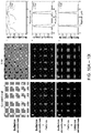
- the inventors were concerned that interference between neighboring foci and transfer of energy from the central intensity maxima to sidelobes would significantly diminish illumination contrast in the focal plane. Indeed, when imaging fluorescent dye in TIRF mode, substantial background fluorescence was observed between excitation foci (albeit still less than observed when imaging conventionally, due to the dramatic reduction of out-of-focus fluorescence in TIRF). However, individual foci were sharply defined and the extraneous background could be readily removed with the pinhole array intrinsic to the setup as shown in FIGS. 10A - 10I .
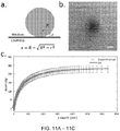
- TIRF was maintained during the imaging process by measuring the depth of the evanescent field with index-matched silica beads as shown in FIGS. 11A - 11C , which found this value to be 123 nm (117 nm, 129 nm, 95% confidence interval).
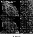
- Qualitative comparisons on fixed microtubule samples also demonstrated the improved sectioning in TIRF relative to conventional instant SIM are shown in the images of FIGS. 12A - 12D .
- the test system measured system resolution on 100 nm fluorescent beads shown in FIGS. 13A - 13F .
- Performing operations, such as descanning, pinholing, locally contracting, and rescanning reduced the apparent fluorescent bead diameter to 194 +/- 20 nm, and resolution could be further improved after deconvolution (10 iterations, Richardson-Lucy deconvolution) to 115 +/- 13 nm.
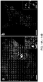
- FIGS. 14A and 14B As individual GFP-labeled myosin IIA heads and void areas within GFP-FCHO2 puncta, subdiffractive structural features that have previously been resolved with TIRF/SIM were discerned.
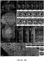
- the test used the instant TIRF/SIM system 100 to examine the dynamics of protein distributions in living cells ( FIGS. 8A - 8H ).
- the test recorded microtubule dynamics over 500 time-points by imaging 3X-EGFP-EMTB in Jurkat T cells after they settled on anti-CD3 antibody coated coverslips ( FIG. 8A ).
- the imaging rate of 20 Hz was sufficient to easily follow buckling, shortening, and sliding of microtubule bundles at the base of the cell within the evanescent TIRF field ( FIG. 8A ).
- the test recorded the dynamics of the small GTPase HRas, which is lipidated and then targeted to the plasma membrane15.
- Halotag-HRAS (labeled with Janelia Fluor 54916) in combination with GFP-VSVG ( FIG. 8E ), highlighting the ability of instant TIRF SIM for live, dual-color imaging at the plasma membrane.
- VSVG showed some localization around Ras microdomains within the cell interior ( FIG. 8G ), but the inventors also observed preferential enrichment of VSVG at the cell boundary, particularly at cell filopodia and filamentous structures.
- GFP-HRAS was imaged with dsRED-ER ( FIG. 8H ), marking the endoplamic reticulum (ER).
- the ER mostly appeared as a set of punctate spots and occasional tubules, presumably representing ER proximal to the plasma membrane.
- punctate ER structures occasionally colocalized with Ras, the protein distributions were mostly distinct and exhibited different dynamics consistent with their differential localization and function within the cell.
- the spatial resolution of the technique proved helpful in resolving the fission of Ras microclusters adjacent to more stable ER contacts, a phenomenon otherwise obscured by diffraction ( FIG. 8I ).
- the test allowed visualization of intracellular calcium flux, actin, and myosin IIB dynamics in live cells. These examples all underscore the ability of instant TIRF SIM to enable super-resolution imaging well matched to the dynamics of interest, either matching or surpassing the image acquisition rate offered by more classic TIRF SIM systems.
- FIGS. 9B and 9C A closer analysis at the single particle level shown in FIGS. 9B and 9C also revealed qualitative differences in particle motion, with some particles undergoing diffusive motion, as revealed by a linear mean square displacement (MSD) vs. time and others showing supralinear MSD vs. time ( FIG. 9E ) with bouts of directed motion illustrated in FIG. 9D . It was noted that imaging at slower frame rates would artificially shorten track lengths, offering a less accurate representation of the underlying motion ( FIGS. 17A and 17B ).
- the Instant TIRF-SIM system 100 provides fundamentally faster operation than classic TIRF-SIM systems, as only one image needs to be acquired, instead of the standard nine. Additional advantages of the implementation over alternative approaches include less read noise (since fewer images are acquired) and less computational processing (the method requires only simple deconvolution of the raw images, instead of extensive image processing in Fourier space). Although the spatial resolution we report ( ⁇ 115 nm) is ⁇ 40% less than claimed in previous state of the art linear TIRF-SIM, the existing implementation of instant TIRF-SIM is ⁇ 50 fold faster, as the test shown in FIG. 9 demonstrated by imaging at frame rates up to 100 Hz
- the instant TIRF SIM 100 used a 1.7 NA objective (Olympus, APON100XHOTIRF) for excitation and detection.
- a relay system was inserted into the excitation arm of the instant SIM to block these rays.
- the excitation laser power was measured immediately prior to the objective. Depending on the sample, the average power ranged from 0.2 - 2 mW, implying an intensity range from ⁇ 7 - 70 W/cm 2 (given the 58 ⁇ m x 52 ⁇ m field of view).
- Samples were deposited on 20 mm diameter high index coverslips (Olympus, 9-U992) designed for use with the 1.7 NA lens. Coverslips were mounted in a magnetic chamber (Live Cell Instrument, CM-B20-1) that attached to the microscope stage. For temperature maintenance at 37 °C, the magnetic chamber was mounted within an incubation chamber (Okolab, H301-MINI).
- the inventors used two methods to estimate evanescent field depth.
- the inventors instead opted to more directly measure the average evanescent decay length using silica beads (diameter 7.27 ⁇ m, refractive index, 1.42, Bangs Laboratories) placed in a solution of fluorescein dye (Fluka, Cat #32615) ( FIG. 11A ).
- the known diameter of the bead is used to convert the apparent radii observed with TIRF to an axial depth, z ( FIG. 11B ).
- the inventors integrated the intensity I(z) from the coverslip surface to some depth z, as this corresponds to the observed signal F(z) at each depth.
- the first term corresponds to signal derived from 'pure' TIRF (with decay d) and the second term models scattering that is known to contaminate objective-type TIRF (with decay D):
- the PSF was experimentally derived by registering and then averaging the images of 20 100 nm yellow-green beads. Deconvolution was implemented in MATLAB 2017a with the number of iterations N set to 10.
- the inventors performed semi-automated tracking using the TrackMate ImageJ Plugin ( https://imagej.net/TrackMate ).
- DoG Difference of Gaussian
- LAP Linear Assignment Problem
- FIGS. 17A and 17B For the cropped region used for downsampling analysis ( FIGS. 17A and 17B ), images were downsampled 5 times and 10 times in the time domain. Then automated tracking was performed independently for the cropped images (100Hz) and the downsampled images (20 Hz and 10 Hz) without manually adjusting either linking filters or links.
- the inventors computed several quantitative metrics including displacement, distance, instantaneous speed, mean speed and mean squared displacement (MSD).
- the total distance traversed at the j th time point is calculated from the starting point (the 1st time point) and defined as:
- ⁇ t is the time interval between two successive time points.
- the instantaneous speed is also the derivative of the traveled distance D j .
- the mean squared displacement is calculated as
- the excitation intensity in both conventional- and the instant TIRF-SIM 100 is not distributed uniformly even when the excitation is scanned.
- the scanned excitation distribution has highest intensity in the center of the field of view and diminishes at increasing distances perpendicular to the scanning direction.
- the test averaged 100 images of a thin fluorescein layer smoothed the average perpendicular to the scan direction, and divided the raw data by this smoothed average prior to deconvolution.
Landscapes
- Physics & Mathematics (AREA)
- General Physics & Mathematics (AREA)
- Chemical & Material Sciences (AREA)
- Analytical Chemistry (AREA)
- Optics & Photonics (AREA)
- Health & Medical Sciences (AREA)
- Biochemistry (AREA)
- Life Sciences & Earth Sciences (AREA)
- Nuclear Medicine, Radiotherapy & Molecular Imaging (AREA)
- General Health & Medical Sciences (AREA)
- Immunology (AREA)
- Pathology (AREA)
- Engineering & Computer Science (AREA)
- Multimedia (AREA)
- Microscoopes, Condenser (AREA)
- Investigating, Analyzing Materials By Fluorescence Or Luminescence (AREA)
Description
- The present disclosure generally relates to instant structured illumination microscopy (SIM) and in particular to systems and methods for instant structured illumination microscopy where total internal reflection fluorescence (TIRF) techniques may be used to improve optical sectioning and signal-to-noise ratio.
- Total internal reflection occurs when highly inclined light impinges upon a refractive index boundary (with first medium index n1 and second medium index n2, with n1 > n2). According to Snell's Law, n1 sin(theta1) = n2 sin(theta2), where theta1 is the angle of incoming light (measured from the surface normal) and theta2 is the corresponding outgoing angle for the refracted light. For theta2 = pi/2, theta1 = arcsin(n2/n1) is the "critical angle". Any light ray at or exceeding the critical angle is "totally internally reflected", and no light propagates past the interface into the far field on the lower index side of the boundary. Nevertheless, an evanescent wave exists at the interface of the boundary and can excite fluorescent molecules within lambda (the wavelength of excitation) distance from the boundary, on the n2 side. This evanescent wave is used in TIRF to generate very high contrast, high signal-to-noise ratio images of fluorescently-labeled samples, such as the cell membrane, at or near the coverslip boundary.
- A convenient method of setting up TIRF conditions is to use a high numerical aperture objective (typically 1.4 NA or higher, so that aqueous samples with n2 ∼ 1.33, the refractive index of a cell may be imaged) and ensure that only marginal rays pass through the back focal plane of the objective lens. Such "objective side TIRF" has been very successful in cell biology applications, where it has been used for decades.
- Structured illumination microscopy (SIM) is a method that uses sharply patterned light and post-processing of images to enhance image resolution (in its linear form, doubling resolution). In traditional SIM, a series of images are acquired with a camera and computationally processed to improve resolution. This implementation of SIM has also been combined with TIRF, but the implementation still requires 9 raw images relative to normal TIRF microscopy, thereby slowing acquisition 9-fold relative to conventional, diffraction-limited imaging. As such, there is a need for a method that combines SIM with TIRF conditions that does not result in a loss of speed relative to conventional TIRF microscopy.
US2016238827A1 discloses a multi-focal selective illumination microscopy (SIM) system for generating multi-focal patterns of a sample is disclosed. The multi-focal SIM system performs a focusing, scaling and summing operation on each multi-focal pattern in a sequence of multi-focal patterns that completely scan the sample to produce a high resolution composite image.
EP3032312A1 discloses a confocal scanner comprising a first micro lens disk and a second micro lens disk with corresponding microlens arrangement patterns and rotation axis. A beam splitter is configured to guide illumination light via the first micro lens disk to an object and further configured to guide a return light from the object having passed through each micro lens of the first micro lens to the corresponding micro lens of the second micro lens disk. A numerical aperture of each micro lens arranged on the second micro lens disk is greater than a numerical aperture of each micro lens arranged on the first micro lens disk. The confocal scanner is thereby configured to obtain a super resolution image by optical processing. - It is with these observations in mind, among others, that various aspects of the present disclosure were conceived and developed.
-
-
FIG. 1 is a simplified illustration showing a first embodiment of an instant TIRF/SIM system with a radial aperture block, according to aspects of the present disclosure; -
FIG. 2 is a simplified illustration showing a second embodiment of with an instant TIRF/SIM system with a digital micro-mirror device, according to aspects of the present disclosure; -
FIG. 3 is an illustration showing the reflected light rays and the effect of the evanescent wave on the instant TIRF/SIM system, according to aspects of the present disclosure; -
FIG. 4 is a simplified illustration showing a third embodiment of the instant TIRF/SIM system with a spatial light modulator in combination with a radial aperture block, according to aspects of the present disclosure; -
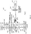
FIG. 5 is a simplified illustration showing a fourth embodiment of the instant TIRF/SIM system with a spinning disk implementation, according to aspects of the present disclosure; -
FIG. 6 is an illustration showing a working model of the first embodiment of the instant TIRF/SIM system, according to aspects of the present disclosure; -
FIGS. 7A-7C show various images taken with the instant TIRF/SIM system andFIGS. 7D and 7E are graphical representations showing comparative line profiles, according to aspects of the present disclosure; -
FIGS. 8A-8H show various images taken with the instant TIRF/SIM system of protein distributions in the vicinity of the plasma membrane over hundreds of time points, according to aspects of the present disclosure; -
FIGS. 9A-9D show various images taken with the instant TIRF/SIM system of Rab11 transfected into U2OS cells, according to aspects of the present disclosure; -
FIGS. 10A-10I show a comparison of excitation and emission patterns between conventional microscopy and the instant TIRF/SIM system, according to aspects of the present disclosure; -
FIGS. 11A-11C show an estimation of evanescent field decay length with silica beads placed in a fluorescent dye, according to aspects of the present disclosure; -
FIGS. 12A-12D show comparative images between a conventional instant SIM system and the instant TIRF/SIM system, according to aspects of the present disclosure; -
FIGS. 13A-13F show comparative representative bead images between a conventional SIM system and the instant TIRF/SIM system, according to aspects of the present disclosure; -
FIGS. 14A and 14B show biological resolution standards for the instant TIRF/SIM system , according to aspects of the present disclosure; -
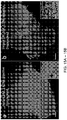
FIGS. 15A and 15B show comparative images of a conventional SIM system and the instant TIRF/SIM system, according to aspects of the present disclosure; -
FIGS. 16A-16D are histograms of total displacement and mean speed of tracked particles, according to aspects of the present disclosure; -
FIGS. 17A and 17B show images illustrating the effect of temporal undersampling on automated tracking, according to aspects of the present disclosure; -
FIG. 18 is a simplified illustration showing a multi-focal pattern with a plurality of focal points; and -
FIG. 19 is a simplified illustration showing a scaling operation that scales in-focus fluorescent emissions resulting from a multi-focal fluorescence pattern emitted by a sample. - Corresponding reference characters indicate corresponding elements among the view of the drawings. The headings used in the figures do not limit the scope of the claims.
- Systems and methods for applying total internal reflection fluorescence (TIRF) to instant structured illumination microscopy (SIM) are disclosed herein. In some embodiments, the instant TIRF/SIM system includes a radial aperture block positioned at a plane conjugate to the back focal plane of the objective lens, thus allowing only high-angle marginal annular light beams from a laser source to excite the sample. In some embodiments, the radial aperture block of the first embodiment of the instant TIRF/SIM system is replaced with a digital micromirror device (DMD) for varying the evanescent wave to allow ∼nm localization of features in the axial direction. In some embodiments, a spatial light modulator (SLM) is used to alter the phase of the excitation to optimally induce evanescent, patterned excitation at the sample. In some embodiments, the radial aperture block is combined with a spinning disk arrangement including a pair of spinning disks having converging microlenses which are arranged with a spinning disk having pinholes to produce contracted non-inverted images of fluorescent foci being emitted by the sample. Combinations of the SLM, DMD, spinning disk arrangement, and an aperture block are also possible. Various embodiments of the instant TIRF/SIM system allows for high-speed, super-resolution microscopy at very high signal-to-noise (SNR) ratios for biological applications within -200 nm (e.g., the evanescent wave decay length) distance of a coverslip surface. Referring to the drawings, embodiments of an instant TIRF/SIM system are illustrated and generally indicated as 100, 200, 300 and 400 in
FIGS. 1-19 . - Referring to
FIG. 1 , a first embodiment of the instant TIRF/SIM system, designated 100 implements a radial aperture block 110 positioned at a plane conjugate to the back focal plane of the objective lens 124, thus allowing only marginal, annular excitation light beams to pass through for scanning onto a sample 125 as shown inFIG. 1 . In this embodiment, the instant TIRF/SIM system 100 includes an excitation source 102, for example a laser component, that generates anexcitation beam 104 which is transmitted through a first micro lens array 106. The first micro lens array 106 splits theexcitation beam 104 into an array of excitation foci 104A. A first lens 108 is positioned one focal length away from the focal point of the first micro lens array 106. In addition, a radial aperture block 110 is positioned at the front focal plane of the first lens 108 to block central rays emerging from the first lens 108, thereby allowing only high-angle, marginal rays 104B emerging from the first lens 108 to pass through the radial aperture block 110. - An imaging telescope arrangement includes a second lens 112 in line with a
third lens 114 that collectively image the marginal rays 104B that pass through the radial aperture block 110. The second andthird lenses 112 and 114 image the marginal rays 104B to pass through adichroic mirror 116 and onto a two-sided galvanometric mirror 118. In some embodiments, the second andthird lenses 112 and 114 are separated by the sum of their respective focal lengths. The galvanometric mirror 118 redirects and scans the marginal rays 104B through a fourth lens 120 in line with a tube lens 122 and onto the back focal plane of a high numerical aperture objective lens 124. This optical arrangement produces a structured illumination that does not propagate into the sample 125, but evanescently excites the sample 125 with the marginal rays 104B being imaged onto the sample 125 by the objective lens 124. Since the marginal rays impinge upon the sample at an angle that exceeds the critical angle they do not propagate into the sample, instead causing only an evanescent wave that decays exponentially within the sample. The combination of evanescent (caused by the high angle rays that are created by the radial annular block 110), patterned/structured illumination (caused by the micro lens array 106) causes very sharp/high contrast excitation at the sample. In some embodiments, the objective lens 124 may have a numerical aperture > 1.4 NA (i.e. greater than the refractive index of the sample 125), such as 1.65 NA or 1.70 NA. - The resulting excitation 105 generated by the sample 125 scanned by the galvanometer mirror 118 produces a patterned fluorescence emission 105A that may be collected in epi-mode, and then descanned by the galvanometric mirror 118 as the fluorescence emissions 105A are imaged by the arrangement of the objective lens 124, tube lens 122 and fourth lens 120 aligned with the galvanometric mirror 118. The fluorescence emissions 105A emitted by the sample 125 are then separated from the resulting excitation 105 via the
dichroic mirror 116 that redirects the fluorescence emission 105A. - In some embodiments, a fifth lens 126 is positioned one focal length from the galvanometric mirror 118. The fifth lens 126 focuses the descanned fluorescence emission 105A through a second micro lens array 128. The second micro lens array 128 has the same pitch/pattern and lens spacing as the first micro lens array 106 such that the fluorescence emissions 105A are locally contracted into contracted fluorescence emissions 105B without inversion or changing the relative distance between adjacent fluorescence emissions 105A as shown in
FIGS. 18 and 19 . - When the contracted fluorescence emissions 105B are locally contracted the "contraction factor" depends on the respective wavelengths of the
excitation beam 104 and fluorescence emissions 105A and the properties of the radial aperture block 110, and in most cases, may be set at a value of approximately 2. For example, amulti-focal pattern 170 for the fluorescence emissions 105A that may be locally contracted into contracted fluorescence emissions 105B is shown inFIGS. 18 and 19 . In one embodiment, themulti-focal pattern 170 may include a plurality offocal points 172 arranged in a particularmulti-focal pattern 170 defined by the plurality of light beams with eachmulti-focal pattern 170 defining a different arrangement of focal points for the plurality of light beams such thatmulti-focal pattern 170 maximizes the distance between any two nearestfocal points 172 for a given density offocal points 172, thereby minimizing crosstalk. As used herein, the term "crosstalk" refers to the ability of nearby light beams to cause excitation and fluorescence from other focal points to appear as if focal points originate from the focal point in question. In a scanning operation, the plurality of light beams in each multi-focal illumination pattern are rastered onto the sample 125 being illuminated such that the sample 125 emits a plurality of fluorescent emissions. The fluorescent emissions emitted by the sample 125 are rastered in a de-scanning operation which redirects the plurality of fluorescent emissions for removal of out-of-focus fluorescent emissions in a focusing operation. In the focusing operation, out-of-focus fluorescent emissions are blocked and only in-focus fluorescent emissions are allowed to pass through for processing. - The in-focus fluorescent emissions caused by each multi-focal pattern are then scaled using a scaling operation that locally contracts each of fluorescent emissions by a predetermined factor. In one embodiment of the scaling operation illustrated in
FIG. 19 , a local contraction of thefluorescent foci 172 caused in a singlemulti-focal pattern 170 occurs. For example, the local contraction offluorescent foci fluorescent foci 172A' and 172B', respectively, in themulti-focal pattern 170 is such that thedistance 500 between thegeometric centers 175 offluorescent foci distance 502 offluorescent foci fluorescent foci 172 of themulti-focal pattern 170. In other words, the scalingoperation 150 contracts thefluorescent foci 172 locally while keeping the relative distances between each of the fluorescent foci the same. - Referring back to
FIG. 1 , in some embodiments, asixth lens 132 is positioned between opposing first and second mirrors 130 and 134. Thesixth lens 132 is positioned one focal length from the contracted fluorescence emissions 105B and the galvanometer mirror 118 and serves to Fourier-transform the contracted fluorescence emissions 105B onto the galvanometer mirror 118. In this arrangement, the galvanometer mirror 118 and the seventh lens 138 serve to rescan the contracted fluorescence emissions 105B that forms an image onto a detector component 140, such as a camera, to capture the image. - In some embodiments, an emission filter 136 may be interposed between the second mirror 134 and the galvanometer 118 to remove any residual resulting excitation 105 from the contracted fluorescence emissions 105B.
- Referring to
FIG. 2 , another embodiment of the instant TIRF/SIM system, designated 200, substitutes the radial aperture block 110 with a digital micromirror device 210 that varies the evanescent wave to allow ∼nm localization of feature in the axial direction. In this embodiment, the instant TIRF/SIM system 200 includes an excitation source 202, for example a laser component, that generates an excitation beam 204 that is transmitted and passes through a first micro lens array 206. The first micro lens array 206 splits the excitation beam 204 into an array of excitation foci 204A. A first lens 208 is positioned one focal length away from the focal point of the first micro lens array 206. As noted above, the digital micromirror device 210, rather than a radial aperture block 110, may be in communication with the first microlens array 206. In some embodiments, the digital micromirror device 210 is positioned at the front focal plane of the first lens 208 to block all but the high-angle marginal rays 104B emerging from the first lens 208. In other words, all of the pixels of the digital micromirror device 210, except those pixels along the periphery of the digital micromirror device 210, are set to reflect the low-angle central rays off axis, thus effectively removing the low-angle central rays from illuminating the sample 225 in a manner similar to the radial block aperture 110. By varying the number and area of the pixels in this reflective zone, the degree of transmitted marginal rays 104B can also be varied, ultimately corresponding to varying the thickness of the evanescent field at the sample 225. - In some embodiments, an imaging telescope arrangement includes a second lens 212 in line with a third lens 214 that collectively image the marginal rays 204B to pass through a dichroic mirror 216 and onto a two-sided
galvanometric mirror 218. In some embodiments, the second and third lenses 212 and 214 are separated by a distance that is the sum of their respective focal lengths. Thegalvanometric mirror 218 redirects and images the marginal rays 204B along third axis 404 through a fourth lens 220 in line with atube lens 222 and onto the back focal plane of a high numerical aperture objective lens 224. This arrangement produces a structured illumination that does not propagate into a sample 225, but evanescently excites the sample 224 with the marginal rays 204B imaged onto the sample 225 by the objective lens 224. In some embodiments, the objective lens 224 may have a numerical aperture > 1.4 NA, such as 1.65 NA or 1.70 NA. - The resulting
excitation 205 of the sample 225 produces a patterned fluorescence emission 205A that may be collected in epi-mode, and then descanned by thegalvanometric mirror 218 as the fluorescence emissions 205A are imaged by the objective lens 224,tube lens 222 and fourth lens 220 onto thegalvanometer mirror 218. The fluorescence emissions 205A are then separated from the resultingexcitation 205 via the dichroic mirror 216 that redirects the fluorescence emission 205A. - In some embodiments, a fifth lens 226 is positioned one focal length from the
galvanometric mirror 218. The fifth lens 226 focuses the descanned fluorescence emission 205A through a secondmicro lens array 228. The secondmicro lens array 228 has the same pitch/pattern and lens spacing as the first micro lens array 206 such that the fluorescence emissions 205A are locally contracted into contracted fluorescence emissions 205B without inversion or changing the relative distance between adjacent fluorescence emissions 205A. - When the contracted fluorescence emissions 205B are locally contracted the contraction factor depends on the respective wavelengths of the excitation beam 204 and fluorescence emissions 205A and the characteristics of the pattern displayed on the digital micro-mirror device 210 and as discussed above, may be set at a value of approximately 2. In some embodiments, a sixth lens 232 is positioned between opposing first and second mirrors 230 and 234, which is in perpendicular relation to the first, third and fourth axes 400, 404 and 406. The sixth lens 232 is positioned one focal length from the contracted fluorescence emissions 205B and the
galvanometer mirror 218 and serves to Fourier-transform the contracted fluorescence emissions 205B onto thegalvanometer mirror 218. In this arrangement, thegalvanometer 218 and the seventh lens 238 serve to rescan the contracted fluorescence emissions 205B that forms an image onto adetector component 240, such as a camera, to capture the image. - In some embodiments of the instant TIRF/
SIM system 300 the excitation micro lens array 106 may be replaced by a spatial light modulator 304 or other element that enables the phase of the excitation beam 303 to be manipulated while also generating a patterned illumination at thesample 324. By generating an appropriate pattern on the spatial light modulator 304, unwanted interference that would otherwise arise due to the interaction of the high angle, annular structured illumination can be minimized. The front face of the spatial light modulator 304 is imaged onto thesample 324 as indicated by the optical system illustrated inFIG. 4 . All other optics are the same or similar to the first embodiment of the instant TIRF/SIM system 100 illustrated inFIG. 1 . In one embodiment, the excitation pattern produced by the spatial light modulator 304 ofFIG. 3 is required to have the same pitch as the second microlens array 128 ofFIG. 1 . - Referring to
FIG. 4 , a third embodiment of the instant TIRF/SIM system, designated 300, implements a radial aperture block 308 positioned at a plane conjugate to the back focal plane of the objective lens 322, thus allowing only marginal, annular excitation light beams 303B to pass through for scanning onto asample 324. Alternatively, the radial aperture block 308 may be replaced by a digital micromirror device (not shown) and enabling additional functionality (i.e., nm localization in the z direction). In this embodiment, the instant TIRF/SIM system 300 includes an excitation source 302, for example a laser component, that generates an excitation beam 303 which is transmitted onto a spatial light modulator 304 that splits the excitation beam 303 into an array of excitation foci 303A. A first lens 306 is positioned one focal length away from the focal point of the spatial light modulator 304. In addition, a radial aperture block 308 is positioned at the front focal plane of the first lens 306 to block central rays 303C emerging from the first lens 306, thereby allowing only high-angle, marginal rays 303B emerging from the first lens 306 to pass through the radial aperture block 308. - An imaging telescope arrangement includes a second lens 310 in line with a third lens 312 that collectively image the high-angle marginal rays 303B that pass through the radial aperture block 308. The second and third lenses 310 and 312 image the high-angle marginal rays 303B to pass through a dichroic mirror 314 and onto a two-sided galvanometric mirror 316. In some embodiments, the second and third lenses 310 and 312 are separated by the sum of their respective focal lengths. The galvanometric mirror 316 redirects and scans the high-angle marginal rays 303B through a fourth lens 318 in line with a tube lens 320 and onto the back focal plane of a high numerical aperture objective lens 322. This optical arrangement produces a structured illumination that does not propagate into the
sample 324, but evanescently excites thesample 324 with the high-angle marginal rays 303B being imaged onto thesample 324 by the objective lens 322. Since the high-angle marginal rays 303B impinge upon thesample 324 at an angle that exceeds the critical angle, the high-angle marginal rays 303B do not propagate into thesample 324, instead causing only an evanescent wave that decays exponentially within thesample 324. The evanescent wave (caused by the high angle, marginal rays 303B that are created by the radial annular block 308) produces very sharp/high contrast excitation at thesample 324. In some embodiments, the objective lens 322 may have a numerical aperture > 1.4 NA (i.e. greater than the refractive index of the sample), such as 1.65 NA or 1.70 NA. - The resulting excitation 305 generated by the
sample 324 scanned by the galvanometer mirror 316 produces a patterned fluorescence emission 305A that may be collected in epi-mode, and then descanned by the galvanometric mirror 316 as the fluorescence emissions 305A are imaged by the arrangement of the objective lens 322, tube lens 320 and fourth lens 318 aligned with the galvanometric mirror 316. The fluorescence emissions 305A are then separated from the resulting excitation 305 via the dichroic mirror 314 that redirects the fluorescence emission 305A. - In some embodiments, a fifth lens 326 is positioned one focal length from the galvanometric mirror 316. The fifth lens 326 focuses the descanned fluorescence emission 305A through a micro lens array 328. In some embodiments, the micro lens array 328 has a pitch/pattern and lens spacing such that the fluorescence emissions 305A are locally contracted into contracted fluorescence emissions 305B without inversion or changing the relative distance between adjacent fluorescence emissions 305A.
- When the contracted fluorescence emissions 305B are locally contracted the "contraction factor" depends on the respective wavelengths of the excitation beam 303 and fluorescence emissions 305A, the pattern displayed on the spatial light modulator 304, and the characteristics of the radial aperture block 308, and in most cases, may be set at a value of 2. In some embodiments, a sixth lens 334 is positioned between opposing first and
second mirrors 330 and 332. The sixth lens 334 is positioned one focal length from the contracted fluorescence emissions 305B and the galvanometer mirror 316 and serves to Fourier-transform the contracted fluorescence emissions 305B onto the galvanometer mirror 316. In this arrangement, the galvanometer mirror 316 and the seventh lens 338 serve to rescan the contracted fluorescence emissions 305B that forms an image onto a detector component 340, such as a camera, to capture the image. - In some embodiments, an emission filter 336 may be interposed between the
second mirror 332 and the galvanometer 316 to remove any residual resulting excitation 305 from the contracted fluorescence emissions 305B. - Referring to
FIG. 5 , a fourth embodiment of the instant TIRF/SIM system, designated 400, implements a spinning disk arrangement of the instant TIRF/SIM system 400. In this embodiment, the instant TIRF/SIM system 400 includes an excitation source 402, for example a laser component, that generates an excitation beam 403 which is transmitted through a first spinning disk 404 of converging microlenses that produces a plurality of excitation foci 403A in which the excitation foci 403A cover the entire imaging field of a sample 418. As shown, in some embodiments a first lens 406 forms a telescopic arrangement with second lens 412 that relays the plurality of excitation foci to an intermediate image plane 407 after reflecting off adichroic mirror 410 that is positioned between the first lens 406, which is located one focal length away from the plurality of excitation foci 403A, and the second lens 412. In addition, a radial aperture block 408 is positioned at the co-focal point between the first lens 406 and the second lens 412 in order to filter low angle excitation foci 403A that would otherwise produce subcritical, propagating excitation foci into the sample 418. As noted above, the radial aperture block 408 blocks central rays of the excitation foci 403A emerging from the first lens 406, thereby allowing only high-angle, marginal rays 403B emerging from the first lens 406 to pass through the radial aperture block 408. - As further shown, the high-angle, marginal rays 403B are relayed from the intermediate image plane 407 to the sample 418 via the telescope formed by the arrangement of a tube lens 414 and the objective lens 416. The objective lens 416 may have a higher NA than the refractive index of the sample 418, e.g., numerical aperture greater than 1.33, to ensure TIRF conditions are produced. In some embodiments, the focal lengths and placement of the second lens 412 and the tube lens 414 may be chosen so that the radial aperture block 408 is imaged to the back focal plane of the objective lens 416. Once the sample 418 is illuminated by the high-angle, marginal rays 403B, the fluorescent emissions 405 emitted by the sample 418 is collected in epi-mode and relayed through the second lens 412 and then a third lens 422 (after passing through the dichroic mirror 410) to a spinning
pinhole disk 424 having the same pitch/spacing as the first spinning disk 404 with converging microlenses. The spinningpinhole disk 424 serves to reject scattered fluorescent emissions 405 and unwanted sidelobes in the fluorescent emissions 405. After the fluorescent emissions 405 pass through the spinningpinhole disk 424, a second spinning disk 426 with converging microlenses having the same pitch/spacing as the spinningpinhole disk 424 and first spinning disk 404 is used to locally contract each fluorescent foci of the fluorescent emissions 405 with a contraction factor of approximately 2 using the scaling operation illustrated inFIGS. 18 and 19 , thereby producing contracted, non-inverted fluorescent foci 405A. The respective focal lengths of the first and second spinning disks 404 and 426 and the placement of the second spinning disk 426 are chosen to locally contract the fluorescent foci of the fluorescent emissions 405 the desired degree without inverting the fluorescent foci with respect to the overall image of the sample 418. Finally, the contracted, non-inverted fluorescent foci 405A are relayed to an imaging camera 434 via a final telescope arrangement of a fourth lens 428 and fifth lens 430. In some embodiments, an emission filter 432 may be positioned in the emission path to reject excitation light. In some embodiment, the first and second spinning disks 404 and 426 and the spinningpinhole disk 424 may be spun in tandem to produce a super-resolution image during a single camera exposure. In some embodiments, the sample 418 may be disposed on a coverslip 420 when illuminated by a high angle, marginal rays 403B. - Referring to
FIG. 6 , a working model used for testing of the instant TIRF/SIM system 100 is illustrated. In some embodiments, the instant TIRF/SIM system 100 includes a pair of 488 nm and a 561 nm lasers which are combined and passed through an acousto tunable filter (AOTF) for shuttering, expanding the beam and spatially filtering (e.g., f - 45 mm and f = 400 mm achromats with 100 µm pinhole placed at the co-focal point between the lenses) and directed to an excitation microlens array. In addition, an opaque circular mask was positioned at the co-focal point betweenscan lens 1 and scan lens 2 (e.g., one focal length from the excitation foci produced by the microlens array) that collectively functioned to block subcritical excitation rays, thereby producing annular illumination of the sample. For clarity, only on-axis excitation foci produced by the central microlenses are illustrated after the mask. As shown, scanlens 2 and scanlens 3 relay the mask to a two-sided galvanometric mirror after passing through a compensator plate for reducing astigmatism that would otherwise result as the excitation foci is transmitted through a thick dichroic mirror. A tube lens in combination withscan lens 4 was used to further magnify and relay the mask to the back focal plane of a high NA objective (e.g., NA = 1.7). The scanning of the galvanometric mirror translates the TIRF excitation pattern at the sample. Once the sample was scanned and illuminated, fluorescence emissions from the sample were collected along the same optical path, descanned from the galvanometric mirror and reflected off of the dichroic mirror. Emission-side optics are nearly identical to those used in the description of the instant TIRF/SIM system 100. Note that the distances and ray diagrams shown inFIG. 6 are approximate renderings. - As noted above, TIRF is enabled when highly inclined light with incidence angle Θ ≥ = ΘC = arcsin (n2/n1) impinges upon the boundary between media with indices n1 and n2, with n1 > n2. The inventors reasoned that placing an annular mask at a Fourier image plane (optically conjugate to the back focal plane of the objective) would block all subcritical rays, thereby enforcing TIRF without otherwise perturbing the speed and functionality of the original instant SIM system. Annular illumination has been used to produce a single TIRF spot in diffraction-limited and stimulated emission depletion microscopy, yet for parallelized instant SIM an array of spots is needed.
- The inventors created such a pattern by placing an annulus one focal length away from the foci produced by our excitation microlens array, thus filtering out low angle rays in each excitation focus simultaneously. The resulting beams were relayed to the sample by previous instant SIM optical components, including a two-sided galvanometric mirror conjugate to the back focal plane of the objective (a 1.7 numerical aperture (NA) lens used for the large range of accessible Θ ≥ = ΘC, facilitating TIRF). Emission optics were near identical to the original instant SIM setup (Methods), and included pinhole- and emission microlens arrays with appropriate relay optics as shown in
FIG. 6 . - Since annular excitation produces a focused spot with pronounced sidelobes (due to the Bessel-like character of the excitation), the inventors were concerned that interference between neighboring foci and transfer of energy from the central intensity maxima to sidelobes would significantly diminish illumination contrast in the focal plane. Indeed, when imaging fluorescent dye in TIRF mode, substantial background fluorescence was observed between excitation foci (albeit still less than observed when imaging conventionally, due to the dramatic reduction of out-of-focus fluorescence in TIRF). However, individual foci were sharply defined and the extraneous background could be readily removed with the pinhole array intrinsic to the setup as shown in
FIGS. 10A - 10I . The tests confirmed that TIRF was maintained during the imaging process by measuring the depth of the evanescent field with index-matched silica beads as shown inFIGS. 11A - 11C , which found this value to be 123 nm (117 nm, 129 nm, 95% confidence interval). Qualitative comparisons on fixed microtubule samples also demonstrated the improved sectioning in TIRF relative to conventional instant SIM are shown in the images ofFIGS. 12A - 12D . - The test system measured system resolution on 100 nm fluorescent beads shown in
FIGS. 13A - 13F . With scanned TIRF excitation only, the fluorescent beads were resolved to 249 +/- 11 nm (N = 20 beads). Performing operations, such as descanning, pinholing, locally contracting, and rescanning reduced the apparent fluorescent bead diameter to 194 +/- 20 nm, and resolution could be further improved after deconvolution (10 iterations, Richardson-Lucy deconvolution) to 115 +/- 13 nm. These results were similar to those obtained using conventional illumination with the same objective lens, i.e. with conventional instant SIM implying that the spatial resolution did not degrade in TIRF. Images of fixed cells further confirmed this progressive resolution improvement as shown inFIGS. 7A- 7E, as individual microtubules had an apparent width of ∼128 nm (FIG. 7D ) and the inventors were able to distinguish microtubules spaced 134 nm apart (FIG. 7E ). Qualitative tests in living cells confirmed this resolving power (FIGS. 14A and 14B ), as individual GFP-labeled myosin IIA heads and void areas within GFP-FCHO2 puncta, subdiffractive structural features that have previously been resolved with TIRF/SIM were discerned. - The test used the instant TIRF/
SIM system 100 to examine the dynamics of protein distributions in living cells (FIGS. 8A - 8H ). First, the test recorded microtubule dynamics over 500 time-points by imaging 3X-EGFP-EMTB in Jurkat T cells after they settled on anti-CD3 antibody coated coverslips (FIG. 8A ). The imaging rate of 20 Hz was sufficient to easily follow buckling, shortening, and sliding of microtubule bundles at the base of the cell within the evanescent TIRF field (FIG. 8A ). As a second example, the test recorded the dynamics of the small GTPase HRas, which is lipidated and then targeted to the plasma membrane15. Images were acquired every 0.75 s over 100 timepoints in U2OS cells (FIG. 8C ). Intriguingly, GFP-HRas localized in highly active microdomains at the plasma membrane (FIGS. 8C and 8D ). The high spatiotemporal resolution of the technique revealed rich dynamics of this reticulated pattern, as the test observed reorganization of domains on the second timescale, including transient 'filling in' of the void areas between microdomains (FIG. 8D ), and coordinated, 'wave-like' motion between microdomains. Neither the distribution nor the dynamics of Ras have been previously reported at this length scale in living cells, perhaps due to the lack of spatial resolution or optical sectioning (e.g. in conventional instant SIM at lower NA, microdomains were poorly resolved (FIGS. 15A and 15B ). - The test also imaged Halotag-HRAS (labeled with Janelia Fluor 54916) in combination with GFP-VSVG (
FIG. 8E ), highlighting the ability of instant TIRF SIM for live, dual-color imaging at the plasma membrane. VSVG showed some localization around Ras microdomains within the cell interior (FIG. 8G ), but the inventors also observed preferential enrichment of VSVG at the cell boundary, particularly at cell filopodia and filamentous structures. In a second dual-color example, GFP-HRAS was imaged with dsRED-ER (FIG. 8H ), marking the endoplamic reticulum (ER). Given the optical sectioning of the technique, the ER mostly appeared as a set of punctate spots and occasional tubules, presumably representing ER proximal to the plasma membrane. Although punctate ER structures occasionally colocalized with Ras, the protein distributions were mostly distinct and exhibited different dynamics consistent with their differential localization and function within the cell. The spatial resolution of the technique proved helpful in resolving the fission of Ras microclusters adjacent to more stable ER contacts, a phenomenon otherwise obscured by diffraction (FIG. 8I ). - The test allowed visualization of intracellular calcium flux, actin, and myosin IIB dynamics in live cells. These examples all underscore the ability of instant TIRF SIM to enable super-resolution imaging well matched to the dynamics of interest, either matching or surpassing the image acquisition rate offered by more classic TIRF SIM systems.
- A key advantage, however, in instant SIM is the ability to image at much faster frame rates since the super-resolution image is formed in a single camera exposure. To illustrate this capability, the test imaged GFP-Rab11 in U2OS cells at 37°C at 100 Hz. This imaging rate was sufficient to visualize and track the rapid motion of 980 Rab11 decorated particles (
FIG. 9A ). An analysis of track motion revealed that the majority of particles underwent < 1 µm displacement over our 6 seconds imaging period; yet, tens of particles were observed that showed greater displacements (FIGS 16A-16D ). It was observed that particles that traveled further also traveled faster, with mean speed greater than 1 µm/s (FIGS 16A-16D ) and instantaneous speed in some cases exceeding 10 µm/s (FIGS. 9D and 9F ). A closer analysis at the single particle level shown inFIGS. 9B and 9C also revealed qualitative differences in particle motion, with some particles undergoing diffusive motion, as revealed by a linear mean square displacement (MSD) vs. time and others showing supralinear MSD vs. time (FIG. 9E ) with bouts of directed motion illustrated inFIG. 9D . It was noted that imaging at slower frame rates would artificially shorten track lengths, offering a less accurate representation of the underlying motion (FIGS. 17A and 17B ). - The Instant TIRF-
SIM system 100 provides fundamentally faster operation than classic TIRF-SIM systems, as only one image needs to be acquired, instead of the standard nine. Additional advantages of the implementation over alternative approaches include less read noise (since fewer images are acquired) and less computational processing (the method requires only simple deconvolution of the raw images, instead of extensive image processing in Fourier space). Although the spatial resolution we report (∼115 nm) is ∼40% less than claimed in previous state of the art linear TIRF-SIM, the existing implementation of instant TIRF-SIM is ∼50 fold faster, as the test shown inFIG. 9 demonstrated by imaging at frame rates up to 100 Hz - The
instant TIRF SIM 100 used a 1.7 NA objective (Olympus, APON100XHOTIRF) for excitation and detection. When imaging into aqueous samples with refractive index 1.33, 1-(1.33/1.7) = 0.22 of the objective back focal plane diameter (d BFP) is available for TIRF, implying that sub-critical illumination rays within a diameter 0.78 * d BFP = 0.78 * 2 * NAOBJ * f OBJ = 0.78 * 2 * 1.7 * 1.8 mm = 4.77 mm must be blocked. Second, a relay system was inserted into the excitation arm of the instant SIM to block these rays. Excitation from 488 nm and 561 nm lasers was combined and beam expanded as before, and directed to a microlens array (Amus, f = 6 mm, 222 mm spacing between microlenses, 1 mm thick, 25 mm diameter, antireflection coated over 400-650 nm, APO-Q-P222-F6(633)+CHR) to produce an array of excitation foci. The test used a matched pair of scan lenses (Scanlens optical density 5 on 4" x 4" x 0.090" quartz wafer) at the focal point between scan lenses (and the Fourier plane of the excitation foci produced by the microlens array) to filter subcritical rays. Given the 350 mm/ 190 mm = 1.84x magnification between mask and the back focal plane of the objective, the mask was designed to block the central 2.68 mm * 1.84 = 4.93 mm diameter of the illumination. An iris placed just after the mask ensured that the outer diameter of the beam was -3.33 mm, a diameter that magnified to 3.33 * 1.84 = 6.13 mm, or ∼d BFP, thereby reducing stray light that would otherwise fall outside the objective back focal plane. Alignment of the opaque mask and microlens array were greatly aided by placing the former on a 3-axis translation stage (Thorlabs, LT3, used for correct positioning of the mask image at the back focal plane) and the latter on a uniaxial translation stage (Thorlabs, LNR50M, used to position excitation foci precisely at the focal plane of the objective lens). An alignment reticle (Leica) that screwed into the objective turret was used to further check that the annular illumination pattern was properly positioned (concentric with the optical axis of the objective) and focused at the back focal plane of our objective. - In the emission path, optics were identical to the previous instant SIM design, except that a pinhole array with larger pinholes (Photosciences, Chrome on 0.090" thick quartz, 222 µm pinhole spacing, 50 µm pinhole diameter) and an emission side microlens array with longer focal length (f = 1.86 mm, Amus, APO-Q-P222-F1.86(633)) were used. The total magnification between sample and our scientific grade complementary metal-oxide semiconductor camera (PCO-TECH, pco.edge 4.2) detector was 350 mm / 1.8 mm = 194.4, resulting in an image pixel size of 33.4 nm. These elements are shown in
FIG. 6 . - The excitation laser power was measured immediately prior to the objective. Depending on the sample, the average power ranged from 0.2 - 2 mW, implying an intensity range from ∼7 - 70 W/cm2 (given the 58 µm x 52 µm field of view).
- Samples were deposited on 20 mm diameter high index coverslips (Olympus, 9-U992) designed for use with the 1.7 NA lens. Coverslips were mounted in a magnetic chamber (Live Cell Instrument, CM-B20-1) that attached to the microscope stage. For temperature maintenance at 37 °C, the magnetic chamber was mounted within an incubation chamber (Okolab, H301-MINI).
- The inventors used two methods to estimate evanescent field depth. First, an analytical method was used. For excitation of wavelengthimpinging at angle Θ1 upon an interface with indices n1 and n2, n1 > n2, the intensity I of an evanescent field decays along the optic axis with decay constant d according to I(z) = loexp(-z/d), with


- Since such an intensity distribution is difficult to measure accurately, the inventors instead opted to more directly measure the average evanescent decay length using silica beads (diameter 7.27 µm, refractive index, 1.42, Bangs Laboratories) placed in a solution of fluorescein dye (Fluka, Cat #32615) (
FIG. 11A ). In this method, the known diameter of the bead is used to convert the apparent radii observed with TIRF to an axial depth, z (FIG. 11B ). Following previous work, the inventors integrated the intensity I(z) from the coverslip surface to some depth z, as this corresponds to the observed signal F(z) at each depth. First, the inventors assumed the fluorescence is well modeled by a sum of two exponentials. The first term corresponds to signal derived from 'pure' TIRF (with decay d) and the second term models scattering that is known to contaminate objective-type TIRF (with decay D):

- Fitting the measured fluorescence intensity at each depth (derived at each bead radius) to this expression (
FIG. 11C ) with the Matlab curve fitting toolbox gave d = 123 nm with 95% confidence interval (117nm, 129 nm). The scattering amplitude B represented ∼24 % of the signal. - Unless otherwise indicated, data presented in this test were deconvolved to further enhance spatial resolution. Before deconvolution, background was subtracted from the raw images. Background was estimated by averaging 100 'dark' images acquired without illumination. For deconvolution, the inventors used the Richardson-Lucy algorithm, blurring with a 2D PSF:
For i = 1,2, ... N
- The PSF was experimentally derived by registering and then averaging the images of 20 100 nm yellow-green beads. Deconvolution was implemented in MATLAB 2017a with the number of iterations N set to 10.
- For tracking the particles in the Rab11 dataset (
FIGS. 9A-9F ), the inventors performed semi-automated tracking using the TrackMate ImageJ Plugin (https://imagej.net/TrackMate). For particle detection, the Difference of Gaussian (DoG) detector was used with estimated blob diameter of 0.3 µm, and an initial quality threshold of 120. The particles were further filtered and linked with a simple Linear Assignment Problem (LAP) linker. Linking maximum distance and Gap-closing maximum distance were set to 0.3 µm, and the maximum frame gap was set to 5. For tracking on the whole image (FIGS. 9A-9F ), the linking filters were manually adjusted to filter out obviously spurious tracks. Then manual editing was performed within the plugin interface to improve tracking results. For the cropped region used for downsampling analysis (FIGS. 17A and 17B ), images were downsampled 5 times and 10 times in the time domain. Then automated tracking was performed independently for the cropped images (100Hz) and the downsampled images (20 Hz and 10 Hz) without manually adjusting either linking filters or links. - From the particle tracks (i.e., the sequences of coordinates denoting the position of each tracked particle at each time point), the inventors computed several quantitative metrics including displacement, distance, instantaneous speed, mean speed and mean squared displacement (MSD).
- Given a trajectory consisting of N time points and the particle coordinates at ith time point pi - (xi ,yi ), the distance between any two points pi and pj is defined as the Euclidean norm:

- The total distance traversed at the jth time point is calculated from the starting point (the 1st time point) and defined as:

- and the displacement (magnitude), also known as net distance Fj = d( p 1, p j )
- Then the total distance for the whole trajectory is DN and the total displacement for the whole trajectory is FN .
- The instantaneous speed is defined as:

- where Δt is the time interval between two successive time points. The instantaneous speed is also the derivative of the traveled distance Dj .
- Then the mean speed is calculated as the average of the instantaneous speed:

- The mean squared displacement is calculated as

- For several time-lapse datasets (
FIGS. 8A-8H andFIGS. 9A- 9F), the inventors performed standard bleaching correction using an ImageJ Plugin (Bleach Correction, https://imagej.net/BleachCorrection) with the 'simple ratio' method. - Due to the spatially nonuniform profile of the excitation laser beam, the excitation intensity in both conventional- and the instant TIRF-
SIM 100 is not distributed uniformly even when the excitation is scanned. The scanned excitation distribution has highest intensity in the center of the field of view and diminishes at increasing distances perpendicular to the scanning direction. In an attempt to normalize for this variation in excitation intensity ('flat fielding'), in some of the datasets (FIGS. 8A-8H ,FIGS. 9A-9F ,FIGS. 14A-14B ,FIGS. 16A-16D , andFIGS. 17A-17B ) the test averaged 100 images of a thin fluorescein layer, smoothed the average perpendicular to the scan direction, and divided the raw data by this smoothed average prior to deconvolution.
Claims (10)
- A system (100) for structured illumination microscopy comprising:a light source (102) for generating an excitation light beam (104);a first micro lens array (106) for splitting the excitation beam (104) into an array of excitation foci (104A);a first lens (108) aligned along the first axis and positioned one focal length away from a focal point of the first micro lens array (106), the first lens (108) focusing the array of excitation foci (104A);a radial aperture block (110) aligned along the first axis positioned at a front focal plane of the first lens (108), the radial aperture block (110) being configured to block a plurality of low-angle central rays (104C) of the array of excitation foci (104A), while allowing a plurality of high-angle, marginal rays (104B) of the array of excitation foci (104) to pass through the radial aperture block (110), wherein the high-angle marginal rays (104B) are focused by the first lens (108) along a high-angle and low-angle central rays (104C) are focused by the first lens (108) along a low-angle;a galvanometric mirror (118) aligned and positioned for redirecting and scanning the high-angle, marginal rays (104B) through an objective lens (124) for focusing the redirected high-angle, marginal rays (104B) along a sample (125) that generates an excitation (105) by the sample (124) and then the excitation (105) from the sample (125) is rescanned to generate patterned fluorescence emissions (105A) onto a second microlens array (128) for locally contracting the patterned fluorescence emissions (105B) into a contracted pattern of fluorescence emissions (105B), wherein the high-angle marginal rays (104B) evanescently excite the sample (125); anda mirror arrangement (130, 154) for redirecting the contracted patterned fluorescence emissions (105B) onto a detector (140) for detecting the patterned fluorescence emissions (105B) emitted by the sample (125).
- The system (100) of claim 1, further comprising:
a second lens (112) and a third lens (114) positioned between the radial aperture block (110) and the dichroic mirror (116), wherein the second and third lenses (112, 114) collectively image the high angle, marginal rays (104B) onto the galvanometric mirror (118). - The system (100) of claim 1, wherein the local contraction of the patterned fluorescence emissions (105B) is based on a contraction factor set by the respective wavelengths of the excitation beam (104) and the patterned fluorescence emissions (105B) and the physical characteristics of the radial aperture block (110).
- The system (100) of claim 3 wherein the contraction factor is set at a value of approximately 2.
- A system (200) for structured illumination microscopy comprising:a light source (202) for generating an excitation light beam (204);a first micro-lens array (206) for splitting the excitation beam (204) into an array of excitation foci (204A);a first lens (208) aligned along the first axis and positioned one focal length away from a focal point of the first micro-lens array (206), the first lens (208) focusing the array of excitation foci (204A);a digital micro-mirror device (210) positioned at a front focal plane of the first lens (208), the digital micro-mirror device (210) being operable to reflect a plurality of low-angle central rays of the array of excitation foci (204A) off axis relative to an axis defined by the digital micro-mirror device such that only high-angle marginal rays (204B) that are focused by the first lens (208) along a high-angle are not reflected by the digital micro-mirror device (210);a galvanometric mirror (218) positioned for redirecting and scanning the high-angle, marginal rays (204B) through an objective lens (224) for focusing the redirected high-angle, marginal rays (204B) along a sample (225) that generates an excitation (205) by the sample (225) and then the excitation (205) from the sample (225) is rescanned by the galvanometric mirror (218) to generate a patterned fluorescence emissions (205A) onto a second microlens array (228) for locally contracting the patterned fluorescence emissions (205A) into a contracted patterned fluorescence emissions (205B), wherein the galvanometric mirror (218) scans the high-angle marginal rays (204B) onto a back focal plane of an objective lens (224) that produces a structured illumination that evanescently excites the sample (225); anda mirror arrangement (230, 234) for redirecting the contacted patterned fluorescence emissions (205B) onto a detector for detecting the patterned fluorescence emissions (204A) emitted by the sample.
- The system of claim 5, wherein the number and location of the plurality of pixels in the reflective zone is varied such that the thickness of an evanescent field at the sample (225) is also varied.
- A system (300) for structured illumination microscopy comprising:a light source (302) for generating an excitation light beam (303);a spatial light modulator (304) for controlling the phase of the excitation beam (303) for generating an array of excitation foci (304A) with minimal interference between each excitation foci (304A);a first lens (306) positioned one focal length away from a focal point of the spatial light modulator (304), the first lens (306) focusing the array of excitation foci (304A);a radial aperture block (308) aligned along the first axis positioned at a front focal plane of the first lens (306), the radial aperture block (308) being configured to block a plurality of low-angle central rays (303C) of the array of excitation foci (304A), while allowing a plurality of high-angle, marginal rays (303B) of the array of excitation foci (304A) to pass through the radial aperture block (308), wherein the high-angle marginal rays (303B) are focused by the first lens (306) along a high-angle and low-angle central rays (303C) are focused by the first lens (306) along a low-angle;a galvanometric mirror (316) aligned and positioned for redirecting and scanning the high-angle, marginal rays (303B) through an objective lens (322) for focusing the redirected high-angle, marginal rays (303B) along a sample (324) that generates an excitation (305) by the sample (324) and then the excitation (305) from the sample (324) is rescanned to generate patterned fluorescence emissions (305a) onto a microlens array (328) for locally contracting the patterned fluorescence emissions (305A) into contracted patterned fluorescence emissions (305B), wherein high-angle marginal rays (303B) impinge upon the sample (324) at an angle that exceeds the critical angle the high-angle marginal rays (303B) do not propagate into the sample (324) causing only an evanescent wave to be produced that decays exponentially within the sample (324); anda mirror arrangement (330, 332) for redirecting the contracted patterned fluorescence emissions (305B) onto a detector (340) for detecting the patterned fluorescence emissions (305B) emitted by the sample (324).
- The system of claim 1 or 7, wherein the radial aperture block (308) is positioned at a plane conjugate to the back focal plane of the objective lens (322).
- A system (400) for structured illumination microscopy comprising:a light source (402) for generating an excitation light beam (403);a first spinning disk (404) with a plurality of converging microlenses having a first pitch and spacing, the first spinning disk (404) in communication with the light source (402) for converting the excitation light beam (403) into a plurality of excitation foci (403A) in which the plurality of excitation foci (403A) cover an entire imaging field of a sample (420);a first lens (406) in telescopic arrangement with a second lens (412) that relays the plurality of excitation foci (403A) to an intermediate image plane;a radial aperture block (408) positioned at a focal point between the first lens (406) and the second lens (412), the radial aperture block (408) being operable to block low-angle central rays of the plurality of excitation foci (403A), while allowing high-angle, marginal rays (403B) of the plurality of excitation foci (403A) to pass through the radial aperture block (408), wherein the high-angle marginal rays (403B) are focused by the first lens (406) along a high-angle and low-angle central rays are focused by the first lens (406) along a low-angle;a dichroic mirror (410) positioned between the first lens (406) and the second lens (412) for redirecting the plurality of high-angle, marginal rays (403B) through an objective lens (416) for focusing the redirected high-angle, marginal rays (403B) along the sample (418) that generates fluorescent emissions (405) by the sample (418), wherein the high-angle, marginal rays (403B) evanescently excite the sample (418);a first spinning pinhole disk (424) in communication with the dichroic mirror (410), the first spinning pinhole disk (424) comprising a plurality of pinholes with the pitch and spacing of the first spinning disk (424), the spinning pinhole disk (424) being operable for receiving the fluorescent emissions (405) emitted by the sample (418) and blocking out of focus emissions or scattered light; anda second spinning disk (426) with a plurality of converging microlenses positioned between the spinning pinhole disk (424) and the sample (418) for receiving the fluorescent emissions (405) transmitted through the spinning pinhole disk (424), the second spinning disk (426) with converging microlenses being operable to locally contract the fluorescence emissions (405) into contracted, non-inverted fluorescence emissions (405A), wherein the first and second spinning disks (424, 426) with converging microlenses and the spinning pinhole disk collectively spin in tandem.
- The system of claim 9, wherein spinning in tandem of the first and second spinning disks (424, 426) with converging microlenses and the spinning pinhole disk produces a super-resolution image during a single camera exposure of the detector (434).
Applications Claiming Priority (2)
| Application Number | Priority Date | Filing Date | Title |
|---|---|---|---|
| US201662378307P | 2016-08-23 | 2016-08-23 | |
| PCT/US2017/048234 WO2018039361A1 (en) | 2016-08-23 | 2017-08-23 | Systems and methods for instant total internal reflection fluorescence/structured illumination microscopy |
Publications (3)
| Publication Number | Publication Date |
|---|---|
| EP3403126A1 EP3403126A1 (en) | 2018-11-21 |
| EP3403126A4 EP3403126A4 (en) | 2019-09-11 |
| EP3403126B1 true EP3403126B1 (en) | 2020-12-30 |
Family
ID=61245360
Family Applications (1)
| Application Number | Title | Priority Date | Filing Date |
|---|---|---|---|
| EP17844356.0A Active EP3403126B1 (en) | 2016-08-23 | 2017-08-23 | Systems and methods for instant total internal reflection fluorescence/structured illumination microscopy |
Country Status (4)
| Country | Link |
|---|---|
| US (2) | US10520714B2 (en) |
| EP (1) | EP3403126B1 (en) |
| CN (1) | CN109154715A (en) |
| WO (1) | WO2018039361A1 (en) |
Families Citing this family (18)
| Publication number | Priority date | Publication date | Assignee | Title |
|---|---|---|---|---|
| CN109154715A (en) * | 2016-08-23 | 2019-01-04 | 美利坚合众国,由健康及人类服务部部长代表 | For instant internal reflection fluorescence/structured lighting microscopy system and method |
| DE102017105103A1 (en) * | 2017-03-10 | 2018-09-13 | Carl Zeiss Microscopy Gmbh | 3D microscopy |
| CN109188667B (en) * | 2018-08-10 | 2021-03-12 | 国家纳米科学中心 | Multi-beam array multi-photon heavy scanning microscopic imaging device |
| CN109211854B (en) * | 2018-08-10 | 2021-07-02 | 国家纳米科学中心 | Multi-beam multi-photon rescanning microscopy imaging device |
| CN111665231B (en) * | 2019-03-08 | 2024-12-20 | 南京简智仪器设备有限公司 | Uniform field Raman detection device |
| CN110118764B (en) * | 2019-06-03 | 2020-07-24 | 中国科学院化学研究所 | Wide-field fluorescence imaging laser illumination device and method of using the same |
| CN111145089B (en) * | 2019-11-18 | 2023-06-16 | 中国科学院苏州生物医学工程技术研究所 | High-fidelity image reconstruction method, system, computer equipment and storage medium |
| TWI868263B (en) * | 2019-12-06 | 2025-01-01 | 美商伊路米納有限公司 | Apparatues and methods of estimating values from images and related processor-readable medium |
| CN111399204B (en) * | 2020-02-17 | 2021-06-15 | 浙江大学 | A calibration method for annular scanning imaging system based on rear pupil plane imaging |
| DE102020108117B4 (en) * | 2020-03-24 | 2023-06-15 | Evident Technology Center Europe Gmbh | Microscope and method of operating a microscope |
| NL2026002B1 (en) * | 2020-07-03 | 2022-03-08 | Confocal Nl B V | Re-scan optical systems and methods |
| CN112596230B (en) * | 2020-12-16 | 2022-09-20 | 航天科工微电子系统研究院有限公司 | Light path system for photoelectric tracking active chromatographic illumination |
| CN112816446B (en) * | 2020-12-24 | 2022-02-01 | 四川长虹电器股份有限公司 | Method for detecting powder decay of fluorescent wheel based on fluorescence spectrum |
| CN112858249B (en) * | 2021-03-26 | 2024-10-18 | 北京世纪桑尼科技有限公司 | Super-resolution imaging system |
| EP4413410A4 (en) * | 2021-10-04 | 2025-09-03 | Ultima Genomics Inc | IMAGE WITH ENHANCED RESOLUTION |
| EP4167009A1 (en) * | 2021-10-15 | 2023-04-19 | PreciPoint Innovation GmbH | Microscope and method of operating a microscope |
| EP4212898A1 (en) * | 2022-01-17 | 2023-07-19 | ETH Zurich | Magnetic resonance device comprising a sample spinning apparatus with an electromagnetic field for spinning the sample |
| CN116841028A (en) * | 2023-03-28 | 2023-10-03 | 华南师范大学 | Multi-focus wide-field super-resolution microscopic imaging method and device based on mirror interference enhancement |
Family Cites Families (12)
| Publication number | Priority date | Publication date | Assignee | Title |
|---|---|---|---|---|
| US7066604B2 (en) * | 2002-12-21 | 2006-06-27 | Samsung Electronics Co., Ltd. | Light pipe, color illumination system adopting the light pipe, and projection system employing the color illumination system |
| JP5479224B2 (en) * | 2010-05-27 | 2014-04-23 | キヤノン株式会社 | Catadioptric optical system and imaging apparatus having the same |
| US9753265B2 (en) * | 2011-03-01 | 2017-09-05 | Ge Healthcare Bio-Sciences Corp. | Variable orientation illumination-pattern rotator |
| US10025082B2 (en) * | 2012-02-23 | 2018-07-17 | The United States Of America, As Represented By The Secretary, Department Of Health And Human Services | Multi-focal structured illumination microscopy systems and methods |
| JP6140737B2 (en) | 2012-02-23 | 2017-05-31 | ザ ユナイテッド ステイツ オブ アメリカ, アズ リプレゼンテッド バイ ザ セクレタリー, デパートメント オブ ヘルス アンド ヒューマン サービシーズ | Multifocal structured irradiation microscopy system and method |
| US9360660B2 (en) * | 2012-05-24 | 2016-06-07 | Northwestern University | Methods and apparatus for laser scanning structured illumination microscopy and tomography |
| WO2014070912A1 (en) * | 2012-10-30 | 2014-05-08 | Cohen Adam E | Spatial filter enhanced spinning disk confocal microscope |
| JP6137324B2 (en) * | 2013-09-06 | 2017-05-31 | 株式会社ニコン | Illumination device and structured illumination microscope device |
| CN104102017B (en) * | 2014-07-07 | 2017-09-29 | 西安电子科技大学 | The super diffraction limit imaging system of random scatter optics and method shone based on structure light |
| EP3032312B1 (en) * | 2014-12-08 | 2020-02-26 | Yokogawa Electric Corporation | Confocal scanner and confocal microscope |
| CN105068232B (en) * | 2015-08-31 | 2017-11-24 | 福建师范大学 | A kind of channel structure optical illumination super-resolution imaging method and device |
| CN109154715A (en) * | 2016-08-23 | 2019-01-04 | 美利坚合众国,由健康及人类服务部部长代表 | For instant internal reflection fluorescence/structured lighting microscopy system and method |
-
2017
- 2017-08-23 CN CN201780030158.5A patent/CN109154715A/en active Pending
- 2017-08-23 WO PCT/US2017/048234 patent/WO2018039361A1/en not_active Ceased
- 2017-08-23 EP EP17844356.0A patent/EP3403126B1/en active Active
- 2017-08-23 US US16/326,757 patent/US10520714B2/en active Active
-
2019
- 2019-09-04 US US16/559,805 patent/US10914933B2/en active Active
Non-Patent Citations (1)
| Title |
|---|
| None * |
Also Published As
| Publication number | Publication date |
|---|---|
| WO2018039361A1 (en) | 2018-03-01 |
| CN109154715A (en) | 2019-01-04 |
| US10914933B2 (en) | 2021-02-09 |
| US10520714B2 (en) | 2019-12-31 |
| EP3403126A4 (en) | 2019-09-11 |
| US20190179128A1 (en) | 2019-06-13 |
| US20200064611A1 (en) | 2020-02-27 |
| EP3403126A1 (en) | 2018-11-21 |
Similar Documents
| Publication | Publication Date | Title |
|---|---|---|
| US10914933B2 (en) | Systems and methods for instant total internal reflection fluorescence/ structured illumination microscopy | |
| Guo et al. | Single-shot super-resolution total internal reflection fluorescence microscopy | |
| US9201008B2 (en) | Method and system for obtaining an extended-depth-of-field volumetric image using laser scanning imaging | |
| US8040608B2 (en) | System and method for self-interference fluorescence microscopy, and computer-accessible medium associated therewith | |
| US12216055B2 (en) | Microscope image capturing methods | |
| US20200150446A1 (en) | Method and System for Improving Lateral Resolution in Optical Scanning Microscopy | |
| US20110267688A1 (en) | Microscopy Method and Microscope With Enhanced Resolution | |
| CN101893755B (en) | Fluorescence Microscopy Method and Apparatus for Producing Structured Illumination Using Quadrilateral Pyramidal Mirrors | |
| Jonkman et al. | [18] Resolution in optical microscopy | |
| Murray | Methods for imaging thick specimens: confocal microscopy, deconvolution, and structured illumination | |
| US12546980B2 (en) | Confocal microscope with photon re-allocation | |
| JP7016361B2 (en) | Spatial super-resolution device for fundus fluorescence analysis | |
| NL2008873C2 (en) | Method and apparatus for multiple points of view three-dimensional microscopy. | |
| CN101819319A (en) | Fluorescence microscopy method and device for generating multilayer polished section by using Fresnel biprism | |
| Luo et al. | Resolution and uniformity improvement of parallel confocal microscopy based on microlens arrays and a spatial light modulator | |
| JP2020525811A (en) | Multifocal structured illumination microscope system and method | |
| Sheppard | Confocal microscopy–principles, practice and options | |
| JP5085460B2 (en) | Confocal scanning microscope | |
| Bewersdorf et al. | 4Pi microscopy | |
| Sheppard | Scanning confocal microscopy | |
| JP5765569B2 (en) | Microscope equipment | |
| Paul | Improving Sensitive Microscopy Techniques: SERS, SIM, and Spinning Disks | |
| Li | Super-resolution Fluorescence Microscopy | |
| Cheng et al. | Spatiotemporal focusing-based widefield multiphoton microscopy for fast optical sectioning of thick tissues | |
| Bettarel | In depth Single Molecule Localization Microscopy within 3D multicellular models using Adaptive Optics and PSF engineering |
Legal Events
| Date | Code | Title | Description |
|---|---|---|---|
| STAA | Information on the status of an ep patent application or granted ep patent |
Free format text: STATUS: THE INTERNATIONAL PUBLICATION HAS BEEN MADE |
|
| PUAI | Public reference made under article 153(3) epc to a published international application that has entered the european phase |
Free format text: ORIGINAL CODE: 0009012 |
|
| STAA | Information on the status of an ep patent application or granted ep patent |
Free format text: STATUS: REQUEST FOR EXAMINATION WAS MADE |
|
| 17P | Request for examination filed |
Effective date: 20180817 |
|
| AK | Designated contracting states |
Kind code of ref document: A1 Designated state(s): AL AT BE BG CH CY CZ DE DK EE ES FI FR GB GR HR HU IE IS IT LI LT LU LV MC MK MT NL NO PL PT RO RS SE SI SK SM TR |
|
| AX | Request for extension of the european patent |
Extension state: BA ME |
|
| A4 | Supplementary search report drawn up and despatched |
Effective date: 20190809 |
|
| RIC1 | Information provided on ipc code assigned before grant |
Ipc: G02B 27/58 20060101ALI20190805BHEP Ipc: G02B 21/16 20060101ALI20190805BHEP Ipc: G01N 21/64 20060101ALI20190805BHEP Ipc: G02B 21/00 20060101AFI20190805BHEP Ipc: G02B 21/36 20060101ALI20190805BHEP Ipc: G02B 26/10 20060101ALI20190805BHEP |
|
| DAV | Request for validation of the european patent (deleted) | ||
| DAX | Request for extension of the european patent (deleted) | ||
| GRAP | Despatch of communication of intention to grant a patent |
Free format text: ORIGINAL CODE: EPIDOSNIGR1 |
|
| STAA | Information on the status of an ep patent application or granted ep patent |
Free format text: STATUS: GRANT OF PATENT IS INTENDED |
|
| INTG | Intention to grant announced |
Effective date: 20200714 |
|
| GRAS | Grant fee paid |
Free format text: ORIGINAL CODE: EPIDOSNIGR3 |
|
| GRAA | (expected) grant |
Free format text: ORIGINAL CODE: 0009210 |
|
| STAA | Information on the status of an ep patent application or granted ep patent |
Free format text: STATUS: THE PATENT HAS BEEN GRANTED |
|
| AK | Designated contracting states |
Kind code of ref document: B1 Designated state(s): AL AT BE BG CH CY CZ DE DK EE ES FI FR GB GR HR HU IE IS IT LI LT LU LV MC MK MT NL NO PL PT RO RS SE SI SK SM TR |
|
| REG | Reference to a national code |
Ref country code: GB Ref legal event code: FG4D |
|
| REG | Reference to a national code |
Ref country code: AT Ref legal event code: REF Ref document number: 1350497 Country of ref document: AT Kind code of ref document: T Effective date: 20210115 |
|
| REG | Reference to a national code |
Ref country code: DE Ref legal event code: R096 Ref document number: 602017030688 Country of ref document: DE |
|
| REG | Reference to a national code |
Ref country code: IE Ref legal event code: FG4D |
|
| REG | Reference to a national code |
Ref country code: CH Ref legal event code: NV Representative=s name: HEPP WENGER RYFFEL AG, CH |
|
| PG25 | Lapsed in a contracting state [announced via postgrant information from national office to epo] |
Ref country code: GR Free format text: LAPSE BECAUSE OF FAILURE TO SUBMIT A TRANSLATION OF THE DESCRIPTION OR TO PAY THE FEE WITHIN THE PRESCRIBED TIME-LIMIT Effective date: 20210331 Ref country code: NO Free format text: LAPSE BECAUSE OF FAILURE TO SUBMIT A TRANSLATION OF THE DESCRIPTION OR TO PAY THE FEE WITHIN THE PRESCRIBED TIME-LIMIT Effective date: 20210330 Ref country code: FI Free format text: LAPSE BECAUSE OF FAILURE TO SUBMIT A TRANSLATION OF THE DESCRIPTION OR TO PAY THE FEE WITHIN THE PRESCRIBED TIME-LIMIT Effective date: 20201230 Ref country code: RS Free format text: LAPSE BECAUSE OF FAILURE TO SUBMIT A TRANSLATION OF THE DESCRIPTION OR TO PAY THE FEE WITHIN THE PRESCRIBED TIME-LIMIT Effective date: 20201230 |
|
| REG | Reference to a national code |
Ref country code: AT Ref legal event code: MK05 Ref document number: 1350497 Country of ref document: AT Kind code of ref document: T Effective date: 20201230 |
|
| PG25 | Lapsed in a contracting state [announced via postgrant information from national office to epo] |
Ref country code: SE Free format text: LAPSE BECAUSE OF FAILURE TO SUBMIT A TRANSLATION OF THE DESCRIPTION OR TO PAY THE FEE WITHIN THE PRESCRIBED TIME-LIMIT Effective date: 20201230 Ref country code: LV Free format text: LAPSE BECAUSE OF FAILURE TO SUBMIT A TRANSLATION OF THE DESCRIPTION OR TO PAY THE FEE WITHIN THE PRESCRIBED TIME-LIMIT Effective date: 20201230 Ref country code: BG Free format text: LAPSE BECAUSE OF FAILURE TO SUBMIT A TRANSLATION OF THE DESCRIPTION OR TO PAY THE FEE WITHIN THE PRESCRIBED TIME-LIMIT Effective date: 20210330 |
|
| REG | Reference to a national code |
Ref country code: NL Ref legal event code: MP Effective date: 20201230 |
|
| PG25 | Lapsed in a contracting state [announced via postgrant information from national office to epo] |
Ref country code: HR Free format text: LAPSE BECAUSE OF FAILURE TO SUBMIT A TRANSLATION OF THE DESCRIPTION OR TO PAY THE FEE WITHIN THE PRESCRIBED TIME-LIMIT Effective date: 20201230 |
|
| REG | Reference to a national code |
Ref country code: LT Ref legal event code: MG9D |
|
| PG25 | Lapsed in a contracting state [announced via postgrant information from national office to epo] |
Ref country code: SK Free format text: LAPSE BECAUSE OF FAILURE TO SUBMIT A TRANSLATION OF THE DESCRIPTION OR TO PAY THE FEE WITHIN THE PRESCRIBED TIME-LIMIT Effective date: 20201230 Ref country code: PT Free format text: LAPSE BECAUSE OF FAILURE TO SUBMIT A TRANSLATION OF THE DESCRIPTION OR TO PAY THE FEE WITHIN THE PRESCRIBED TIME-LIMIT Effective date: 20210430 Ref country code: RO Free format text: LAPSE BECAUSE OF FAILURE TO SUBMIT A TRANSLATION OF THE DESCRIPTION OR TO PAY THE FEE WITHIN THE PRESCRIBED TIME-LIMIT Effective date: 20201230 Ref country code: CZ Free format text: LAPSE BECAUSE OF FAILURE TO SUBMIT A TRANSLATION OF THE DESCRIPTION OR TO PAY THE FEE WITHIN THE PRESCRIBED TIME-LIMIT Effective date: 20201230 Ref country code: EE Free format text: LAPSE BECAUSE OF FAILURE TO SUBMIT A TRANSLATION OF THE DESCRIPTION OR TO PAY THE FEE WITHIN THE PRESCRIBED TIME-LIMIT Effective date: 20201230 Ref country code: LT Free format text: LAPSE BECAUSE OF FAILURE TO SUBMIT A TRANSLATION OF THE DESCRIPTION OR TO PAY THE FEE WITHIN THE PRESCRIBED TIME-LIMIT Effective date: 20201230 |
|
| PG25 | Lapsed in a contracting state [announced via postgrant information from national office to epo] |
Ref country code: AT Free format text: LAPSE BECAUSE OF FAILURE TO SUBMIT A TRANSLATION OF THE DESCRIPTION OR TO PAY THE FEE WITHIN THE PRESCRIBED TIME-LIMIT Effective date: 20201230 Ref country code: PL Free format text: LAPSE BECAUSE OF FAILURE TO SUBMIT A TRANSLATION OF THE DESCRIPTION OR TO PAY THE FEE WITHIN THE PRESCRIBED TIME-LIMIT Effective date: 20201230 |
|
| PG25 | Lapsed in a contracting state [announced via postgrant information from national office to epo] |
Ref country code: IS Free format text: LAPSE BECAUSE OF FAILURE TO SUBMIT A TRANSLATION OF THE DESCRIPTION OR TO PAY THE FEE WITHIN THE PRESCRIBED TIME-LIMIT Effective date: 20210430 |
|
| REG | Reference to a national code |
Ref country code: DE Ref legal event code: R097 Ref document number: 602017030688 Country of ref document: DE |
|
| PG25 | Lapsed in a contracting state [announced via postgrant information from national office to epo] |
Ref country code: AL Free format text: LAPSE BECAUSE OF FAILURE TO SUBMIT A TRANSLATION OF THE DESCRIPTION OR TO PAY THE FEE WITHIN THE PRESCRIBED TIME-LIMIT Effective date: 20201230 Ref country code: IT Free format text: LAPSE BECAUSE OF FAILURE TO SUBMIT A TRANSLATION OF THE DESCRIPTION OR TO PAY THE FEE WITHIN THE PRESCRIBED TIME-LIMIT Effective date: 20201230 |
|
| PLBE | No opposition filed within time limit |
Free format text: ORIGINAL CODE: 0009261 |
|
| STAA | Information on the status of an ep patent application or granted ep patent |
Free format text: STATUS: NO OPPOSITION FILED WITHIN TIME LIMIT |
|
| PG25 | Lapsed in a contracting state [announced via postgrant information from national office to epo] |
Ref country code: DK Free format text: LAPSE BECAUSE OF FAILURE TO SUBMIT A TRANSLATION OF THE DESCRIPTION OR TO PAY THE FEE WITHIN THE PRESCRIBED TIME-LIMIT Effective date: 20201230 |
|
| 26N | No opposition filed |
Effective date: 20211001 |
|
| PG25 | Lapsed in a contracting state [announced via postgrant information from national office to epo] |
Ref country code: ES Free format text: LAPSE BECAUSE OF FAILURE TO SUBMIT A TRANSLATION OF THE DESCRIPTION OR TO PAY THE FEE WITHIN THE PRESCRIBED TIME-LIMIT Effective date: 20201230 |
|
| PG25 | Lapsed in a contracting state [announced via postgrant information from national office to epo] |
Ref country code: SI Free format text: LAPSE BECAUSE OF FAILURE TO SUBMIT A TRANSLATION OF THE DESCRIPTION OR TO PAY THE FEE WITHIN THE PRESCRIBED TIME-LIMIT Effective date: 20201230 |
|
| PG25 | Lapsed in a contracting state [announced via postgrant information from national office to epo] |
Ref country code: MC Free format text: LAPSE BECAUSE OF FAILURE TO SUBMIT A TRANSLATION OF THE DESCRIPTION OR TO PAY THE FEE WITHIN THE PRESCRIBED TIME-LIMIT Effective date: 20201230 |
|
| REG | Reference to a national code |
Ref country code: BE Ref legal event code: MM Effective date: 20210831 |
|
| PG25 | Lapsed in a contracting state [announced via postgrant information from national office to epo] |
Ref country code: IS Free format text: LAPSE BECAUSE OF FAILURE TO SUBMIT A TRANSLATION OF THE DESCRIPTION OR TO PAY THE FEE WITHIN THE PRESCRIBED TIME-LIMIT Effective date: 20210430 Ref country code: LU Free format text: LAPSE BECAUSE OF NON-PAYMENT OF DUE FEES Effective date: 20210823 |
|
| PG25 | Lapsed in a contracting state [announced via postgrant information from national office to epo] |
Ref country code: IE Free format text: LAPSE BECAUSE OF NON-PAYMENT OF DUE FEES Effective date: 20210823 Ref country code: BE Free format text: LAPSE BECAUSE OF NON-PAYMENT OF DUE FEES Effective date: 20210831 |
|
| PG25 | Lapsed in a contracting state [announced via postgrant information from national office to epo] |
Ref country code: NL Free format text: LAPSE BECAUSE OF NON-PAYMENT OF DUE FEES Effective date: 20201230 Ref country code: CY Free format text: LAPSE BECAUSE OF FAILURE TO SUBMIT A TRANSLATION OF THE DESCRIPTION OR TO PAY THE FEE WITHIN THE PRESCRIBED TIME-LIMIT Effective date: 20201230 |
|
| P01 | Opt-out of the competence of the unified patent court (upc) registered |
Effective date: 20230527 |
|
| PG25 | Lapsed in a contracting state [announced via postgrant information from national office to epo] |
Ref country code: SM Free format text: LAPSE BECAUSE OF FAILURE TO SUBMIT A TRANSLATION OF THE DESCRIPTION OR TO PAY THE FEE WITHIN THE PRESCRIBED TIME-LIMIT Effective date: 20201230 Ref country code: HU Free format text: LAPSE BECAUSE OF FAILURE TO SUBMIT A TRANSLATION OF THE DESCRIPTION OR TO PAY THE FEE WITHIN THE PRESCRIBED TIME-LIMIT; INVALID AB INITIO Effective date: 20170823 |
|
| PG25 | Lapsed in a contracting state [announced via postgrant information from national office to epo] |
Ref country code: MK Free format text: LAPSE BECAUSE OF FAILURE TO SUBMIT A TRANSLATION OF THE DESCRIPTION OR TO PAY THE FEE WITHIN THE PRESCRIBED TIME-LIMIT Effective date: 20201230 |
|
| PG25 | Lapsed in a contracting state [announced via postgrant information from national office to epo] |
Ref country code: MT Free format text: LAPSE BECAUSE OF FAILURE TO SUBMIT A TRANSLATION OF THE DESCRIPTION OR TO PAY THE FEE WITHIN THE PRESCRIBED TIME-LIMIT Effective date: 20201230 |
|
| PGFP | Annual fee paid to national office [announced via postgrant information from national office to epo] |
Ref country code: DE Payment date: 20250827 Year of fee payment: 9 |
|
| PGFP | Annual fee paid to national office [announced via postgrant information from national office to epo] |
Ref country code: GB Payment date: 20250827 Year of fee payment: 9 |
|
| PGFP | Annual fee paid to national office [announced via postgrant information from national office to epo] |
Ref country code: FR Payment date: 20250825 Year of fee payment: 9 |
|
| PGFP | Annual fee paid to national office [announced via postgrant information from national office to epo] |
Ref country code: CH Payment date: 20250901 Year of fee payment: 9 |
|
| PG25 | Lapsed in a contracting state [announced via postgrant information from national office to epo] |
Ref country code: TR Free format text: LAPSE BECAUSE OF FAILURE TO SUBMIT A TRANSLATION OF THE DESCRIPTION OR TO PAY THE FEE WITHIN THE PRESCRIBED TIME-LIMIT Effective date: 20201230 |