EP3403059B1 - Coriolis flowsensor - Google Patents
Coriolis flowsensor Download PDFInfo
- Publication number
- EP3403059B1 EP3403059B1 EP17702968.3A EP17702968A EP3403059B1 EP 3403059 B1 EP3403059 B1 EP 3403059B1 EP 17702968 A EP17702968 A EP 17702968A EP 3403059 B1 EP3403059 B1 EP 3403059B1
- Authority
- EP
- European Patent Office
- Prior art keywords
- coriolis
- tube
- detection elements
- excitation
- flow sensor
- Prior art date
- Legal status (The legal status is an assumption and is not a legal conclusion. Google has not performed a legal analysis and makes no representation as to the accuracy of the status listed.)
- Active
Links
Images

Classifications
-
- G—PHYSICS
- G01—MEASURING; TESTING
- G01F—MEASURING VOLUME, VOLUME FLOW, MASS FLOW OR LIQUID LEVEL; METERING BY VOLUME
- G01F1/00—Measuring the volume flow or mass flow of fluid or fluent solid material wherein the fluid passes through a meter in a continuous flow
- G01F1/76—Devices for measuring mass flow of a fluid or a fluent solid material
- G01F1/78—Direct mass flowmeters
- G01F1/80—Direct mass flowmeters operating by measuring pressure, force, momentum, or frequency of a fluid flow to which a rotational movement has been imparted
- G01F1/84—Coriolis or gyroscopic mass flowmeters
- G01F1/8409—Coriolis or gyroscopic mass flowmeters constructional details
- G01F1/844—Coriolis or gyroscopic mass flowmeters constructional details microfluidic or miniaturised flowmeters
- G01F1/8445—Coriolis or gyroscopic mass flowmeters constructional details microfluidic or miniaturised flowmeters micromachined flowmeters
-
- G—PHYSICS
- G01—MEASURING; TESTING
- G01F—MEASURING VOLUME, VOLUME FLOW, MASS FLOW OR LIQUID LEVEL; METERING BY VOLUME
- G01F1/00—Measuring the volume flow or mass flow of fluid or fluent solid material wherein the fluid passes through a meter in a continuous flow
- G01F1/76—Devices for measuring mass flow of a fluid or a fluent solid material
- G01F1/78—Direct mass flowmeters
- G01F1/80—Direct mass flowmeters operating by measuring pressure, force, momentum, or frequency of a fluid flow to which a rotational movement has been imparted
- G01F1/84—Coriolis or gyroscopic mass flowmeters
- G01F1/8409—Coriolis or gyroscopic mass flowmeters constructional details
- G01F1/8427—Coriolis or gyroscopic mass flowmeters constructional details detectors
-
- G—PHYSICS
- G01—MEASURING; TESTING
- G01F—MEASURING VOLUME, VOLUME FLOW, MASS FLOW OR LIQUID LEVEL; METERING BY VOLUME
- G01F1/00—Measuring the volume flow or mass flow of fluid or fluent solid material wherein the fluid passes through a meter in a continuous flow
- G01F1/76—Devices for measuring mass flow of a fluid or a fluent solid material
- G01F1/78—Direct mass flowmeters
- G01F1/80—Direct mass flowmeters operating by measuring pressure, force, momentum, or frequency of a fluid flow to which a rotational movement has been imparted
- G01F1/84—Coriolis or gyroscopic mass flowmeters
- G01F1/845—Coriolis or gyroscopic mass flowmeters arrangements of measuring means, e.g., of measuring conduits
- G01F1/8468—Coriolis or gyroscopic mass flowmeters arrangements of measuring means, e.g., of measuring conduits vibrating measuring conduits
- G01F1/849—Coriolis or gyroscopic mass flowmeters arrangements of measuring means, e.g., of measuring conduits vibrating measuring conduits having straight measuring conduits
Definitions
- the invention relates to a Coriolis flow sensor, comprising at least a Coriolis-tube, excitation means for causing the tube to oscillate, as well as detection means for detecting at least a measure of displacements of parts of the tube during operation.
- a Coriolis flow sensor having a loop-shaped Coriolis tube is known from EP 1 719 982 A1 .
- Various types of loop-shaped Coriolis tubes are described therein, both of the single loop type and of the (continuous) double loop type.
- the present invention relates to any of these types, but is not restricted thereto.
- a Coriolis flow sensor (also indicated as flow sensor of the Coriolis type) comprises at least one vibrating tube, often denoted Coriolis tube, flow tube, or sensing tube. This tube or these tubes is or are fastened at both ends to the housing of the instrument. These tube ends serve at the same time as feed and discharge ducts for the liquid or gas flow to be measured.
- a Coriolis flow sensor comprises two further subsystems, i.e. one for excitation and one for detection.
- the excitation system (exciter) is arranged for bringing the tube into vibration.
- the detection system is arranged for detecting at least a measure of the displacements of one or several points of the tube as a function of time.
- the vibration of the tube generated by the exciter takes place at a more or less fixed frequency which varies slightly as a function, amongst others, of the density of the medium flowing through the tube.
- the vibration frequency is almost always a natural frequency of the tube so that a maximum amplitude can be achieved with a minimum energy input.
- a Coriolis mass flow sensor When measuring large fluid flows, a Coriolis mass flow sensor is generally the preferred sensor due to its medium independent mass flow measurement. While conventional Coriolis flow sensors are widely used, there are no commercially available micromachined Coriolis flow sensors. The most accurate known micro Coriolis mass flow sensor is capable of measuring from 0.55 ⁇ g s -1 up to 277 ⁇ g s -1 . Instead, thermal flow sensors are used for very low flows, but these kinds of sensors depend on fluid properties and need calibration for each fluid. Using a Coriolis flow sensor for these flows as well would eliminate the need for calibration for each fluid and allows measurement of unknown fluids, e.g. reaction products.
- a Coriolis flow sensor comprising a Coriolis tube; excitation means for oscillating said tube about an excitation axis, wherein the Coriolis tube comprises a measuring tube part that extends transversely with respect to the excitation axis; as well as detection means for detecting, in use, at least a measure for movements of part of the Coriolis tube, wherein the detection means comprise two detection elements that are positioned along one side of the measuring tube part.
- This Coriolis flow sensor is, however, relatively sensitive to excitation oscillations and it is relatively difficult to maintain the same sensitivity to Coriolis displacements.
- the Coriolis tube comprises a measuring tube part that extends transversely with respect to the excitation axis.
- the excitation axis may lie in a plane defined by the Coriolis tube.
- the excitation axis may substantially coincide with a symmetry axis of the Coriolis tube.
- the excitation means are designed to exert a twisting oscillation of the Coriolis tube about the excitation axis.
- the Coriolis displacement is due to an oscillation about an oscillation axis that extends substantially transverse to the excitation axis and lies in the plane defined by the Coriolis tube.
- the Coriolis flow sensor is characterized in that the detection means comprise two detection elements that are positioned on opposite sides of the measuring tube part, partly overlapping the excitation axis. In this way, the detection elements are positioned closer to the excitation axis, such that the measured excitation oscillation is reduced.
- the measured actuation amplitude has been reduced by reducing the distance between the read-out structures, i.e. the detection elements, and the distance can be reduced further by changing the location of the read-out structures, i.e. placing the detection elements on opposite sides of the Coriolis-tube.
- the read-out structures e.g. combs
- the center of each detection element e.g. comb
- the sensitivity of the Coriolis flow sensor is increased as the measured displacement is to a larger extent the result of the Coriolis displacement.
- the detection elements are provided such that they partly overlap the excitation axis. This allows the detection elements to be positioned closer to the center of the twist axis, resulting in a reduced sensitivity to excitation oscillations, whilst maintaining the same sensitivity to Coriolis displacements.
- the detection elements are provided behind each other, partly overlapping, as seen in a direction parallel to the excitation axis, and provided on opposite sides of the measuring tube part.
- the detection elements are substantially positioned in the plane defined by the Coriolis tube, on opposite sides of the measuring tube part.
- At least one of the two detection elements is positioned asymmetrical with respect to the excitation axis.
- the center of the read out structure e.g. the comb, is placed at a distance from the excitation or twist axis.
- the distance between the twist axis and the center of the comb structures can also be decreased further, however, this also increases the influence of effects that might change the exact location of the twist axis (e.g. imperfections in the fabrication process), which is undesirable.
- a Coriolis flow sensor was designed, fabricated and tested which can measure up to 50 ⁇ g s-1 at a maximum pressure drop of 1 bar with a zero stability of 14 ng s-1, an improvement by a factor 40 compared to Coriolis flow sensors according to the prior art.
- the Coriolis tube is substantially loop shaped, such as rectangular loop shaped.
- Other loop shapes such as triangular, trapezoidal, or U-shaped, are also possible.
- each of the two detection elements is positioned asymmetrical with respect to the excitation axis.
- One of the two detection elements may in an embodiment be positioned further to one side of the excitation axis, and the other one of the two detection elements may be positioned further to the other side of the excitation axis.
- the detection elements are read out electrodes. These are in particular very suitable for micromachined Coriolis flow sensors.
- the measured Coriolis amplitude may be increased in an embodiment by decreasing the diameter of the Coriolis tube.
- the electrical noise level of the detection elements i.e. read-out elements in the form of combs, may also be reduced by increasing the capacitance of the read-out structures. To do this the gap between the comb-fingers of the opposing electrodes is reduced.
- Figures 1 and 2 are descriptions of a prior art flow meter of the Coriolis type as described in EP2078936 B1 , to which the invention may be applied.
- the reference to these figures is used to clarify the general build of these types of flowmeters, and the method of operation.
- Fig. 1a shows a system chip 17 comprising a monocrystalline silicon substrate 1 in which an opening 4 has been etched.
- the system chip 17 in this example has a Coriolis flow sensor with a Coriolis tube 3 of silicon nitride which is freely suspended in the opening 4 as two outer ends of the tube 3 are fixedly connected to the substrate 1.
- An absolute pressure sensor 2 such as a Pirani pressure sensor, may be integrated in or on the substrate 1.
- the Coriolis tube has a loop shape, in this case a rectangular loop shape. Other loop shapes, such as triangular, trapezoidal, or U-shaped, are also possible.
- the system chip 17 is (monolithically) assembled with two mutually opposed permanent magnets 9, 9' which are arranged on a carrier 5, for example a PCB (printed circuit board) of ceramic or synthetic resin material with copper tracks thereon.
- the substrate is manufactured from a ⁇ 1,0,0> Si wafer mounted on the carrier 5.
- the electrical connections between the system chip 17 and the carrier 5 are provided by so-termed bonding wires arranged in groups 6, 7, and 8.
- the bonding wires 6 (from and to the sensor chip) serve for conditioning the chip temperature / c.q. temperature control.
- a local temperature sensor and an (ambient) pressure sensor 2 may be present, if so desired.
- the pressure sensor 2 if present, measures the absolute pressure. This is important because the quality factor of the tube's vibration depends inter alia on the air pressure.
- the bonding wires 7 serve for bringing the freely suspended tube 3 into vibration.
- the bonding wires 8 serve for controlling the read-out elements for the freely suspended tube.
- the freely suspended tube 3 together with the rod magnets 9, 9', a current conductor (wire) 10 on the tube 3, and capacitive sensor elements 11 on the tube and 12 on the system chip 17 forms a so-termed Coriolis flowmeter, which is further clarified in Figs. 2a to 2b .
- a body of soft magnetic material may optionally be provided between the rod magnets 9 and 9' in a location within the loop so as to enhance the efficiency of the magnet arrangement.
- the hydraulic coupling of the system chip 17 to the external world is provided by pressure blocks 13 and 14 ( Fig. 1 b) .
- Fluid connections 16 and 16' are present in the pressure block 14.
- the application of a pressure force between the pressure block 13, the substrate 1, and the pressure block 14 provides a gastight closure of the fluid connection between the tubes 16, 16' and the substrate 1.
- Fig. 1b shows the same device as Fig. 1a , but viewed from the front.
- the 'upper side' of the system chip 17 lies on the centerline 18 of the rod magnets 9 and 9'.
- Fig. 1c shows the same device as Fig. 1a , this time taken on a cross-section at the area of the system chip. Bonding wires 6, 7 for the tube actuation control on the PCB from/to the sensor chip are visible, as are bonding wires 8 for the tube sensing control on the PCB from/to the sensor chip. The bonding wires 6, 7 and 8 thus serve the integrated sensors/transducers of the Coriolis sensor.
- a housing may be provided around the entire assembly for protection; this is not shown.
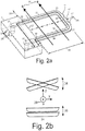
- Fig. 2a shows a U-shaped Coriolis tube 3 that was made by MST technology.
- the Coriolis tube 3 is freely suspended, and is partly embedded in the silicon substrate where it merges into inlet and outlet channels present in the substrate and issuing at the side of the substrate 1 opposite to the freely suspended portion 3.
- the substrate 1 thus forms tube fixation means that fix outer ends 20, 20' of the Coriolis tube 3.
- the applied magnetic field 31 is indicated by arrows B, and the current passed through the conductor 10 on the tube 3 for generating the Lorentz forces is referenced 32.
- a medium enters at 21 and exits at 21'.
- the mass flow of a medium is the mass that passes through a cross-section of the tube per second. If the mass is a self-contained quantity, the mass flow through the U-tube of Fig. 2a must be the same everywhere (otherwise mass will accumulate somewhere, or mass disappear somewhere).
- the mass flow Q has the same (constant) modulus (or vector 'length') everywhere in the tube 3.
- Q points in the positive x-direction in tube portion 22 and in the negative x-direction in tube portion 26.
- Fig. 2b The following method shown in Fig. 2b exists for realizing and applying a Coriolis mass flowmeter with the U-tube 3 of Fig. 2a .
- This (vibratory) actuation movement is referenced 34 in Fig. 2b .
- the resulting Coriolis-induced rotation about the y-axis is proportional to the mass flow and results in a z-movement 35 of the tube portion 24.
- the tube portion 24 performs both movements simultaneously, i.e. the actuating torsional vibration 34 and the flapping movement 35 (proportional to the mass flow).
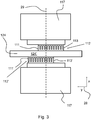
- Fig. 3 shows a top view of a detail of the tube portion 124 in a Coriolis flow sensor according to the invention, which is modified in that the detection means (112, 112') comprise two detection elements (112, 112') that are positioned on opposite sides of the Coriolis tube (124), wherein the detection elements partly overlap each other.
- Fig. 3 shows the excitation axis 29, which lies in the x, y, plane (see coordinate system 28), mainly parallel to the x-axis.
- the Coriolis tube shows a measurement tube part 124' that extends transversely to the excitation axis 29, and that lies substantially in the x,y plane. On opposite sides of the measurement tube part 124', i.e.
- base structures 117 are located to which the detection elements 112, 112' are associated.
- the base structure may be part of the system chip 117.
- the detection elements each comprise capacitive read-out structures each defined by two comb like structures 111, 113, of which one 111, 111' is connected to the measurement tube part 124, and another one 113, 113' is connected to the base part 117.
- capacitive read-out structures are known to those skilled in the art, as described for example in EP2078936B1 with respect to Fig. 6a and 6b.
- the detection elements 112, 112' extend substantially parallel to the measurement tube part 124, and thus extend in the plane defined by the Coriolis tube (x,y plane), mainly in y-direction. It can be seen that the detection elements 112, 112' are provided with an offset with respect to each other, in a direction mainly parallel to the measuring tube part 124 (i.e. the y-direction).
- the detection elements 112, 112' are both positioned asymmetrical with respect to the excitation axis 29. In the embodiment shown, one of the detection elements 112 is provided more to the right, and the other one of the detection elements 112' is provided more to the left.
- the detection elements 112, 112' are positioned closer to the twist axis 29, such that the sensitivity to the excitation displacement (see top of fig. 2b ) is reduced. Advantages of such a positioning have already been described above.
- An alternative fabrication process may be as follows.
- SiRN silicon-rich nitride
- TEOS tetraethyl orthosilicate
- the TEOS layer is removed and a thick (1.5 ⁇ m) layer of LPCVD SiRN is deposited to form the channel wall and seal the etch slits.
- a 10/200 nm thick layer of chromium and gold is sputtered on top of the wafers and patterned to form the tracks and electrodes for actuation and read-out of the chip.
- the last step consists of an isotropic SF6 plasma etch step to remove the silicon around part of the channel, resulting in a free-hanging channel that can vibrate.
Landscapes
- Physics & Mathematics (AREA)
- Fluid Mechanics (AREA)
- General Physics & Mathematics (AREA)
- Chemical & Material Sciences (AREA)
- Dispersion Chemistry (AREA)
- Measuring Volume Flow (AREA)
Description
- The invention relates to a Coriolis flow sensor, comprising at least a Coriolis-tube, excitation means for causing the tube to oscillate, as well as detection means for detecting at least a measure of displacements of parts of the tube during operation.
- A Coriolis flow sensor having a loop-shaped Coriolis tube is known from
EP 1 719 982 A1 . Various types of loop-shaped Coriolis tubes are described therein, both of the single loop type and of the (continuous) double loop type. The present invention relates to any of these types, but is not restricted thereto. - A Coriolis flow sensor (also indicated as flow sensor of the Coriolis type) comprises at least one vibrating tube, often denoted Coriolis tube, flow tube, or sensing tube. This tube or these tubes is or are fastened at both ends to the housing of the instrument. These tube ends serve at the same time as feed and discharge ducts for the liquid or gas flow to be measured.
- Besides the flow tube (or tubes), a Coriolis flow sensor comprises two further subsystems, i.e. one for excitation and one for detection. The excitation system (exciter) is arranged for bringing the tube into vibration. For this purpose, one or several forces or torques are applied to portions of the tube. The detection system is arranged for detecting at least a measure of the displacements of one or several points of the tube as a function of time.
- As a fluid flows in the vibrating tube, it induces Coriolis forces, proportional to the mass-flow, which affect the tube motion and change the mode shape. Measuring the tube displacement using the detection system, the change of the mode shape may be measured, which allows for mass-flow measurements.
- The vibration of the tube generated by the exciter takes place at a more or less fixed frequency which varies slightly as a function, amongst others, of the density of the medium flowing through the tube. The vibration frequency is almost always a natural frequency of the tube so that a maximum amplitude can be achieved with a minimum energy input.
- When measuring large fluid flows, a Coriolis mass flow sensor is generally the preferred sensor due to its medium independent mass flow measurement. While conventional Coriolis flow sensors are widely used, there are no commercially available micromachined Coriolis flow sensors. The most accurate known micro Coriolis mass flow sensor is capable of measuring from 0.55 µg s-1 up to 277 µg s-1. Instead, thermal flow sensors are used for very low flows, but these kinds of sensors depend on fluid properties and need calibration for each fluid. Using a Coriolis flow sensor for these flows as well would eliminate the need for calibration for each fluid and allows measurement of unknown fluids, e.g. reaction products.
- The publication "Integrated Thermal and Microcoriolis Flow Sensing System with a Dynamic Flow Range of More Than Five Decades", published 15 March 2012 by Joost C. Lötters et al, in MICROMACHINES, vol. 3, no. 4, p. 194-203 discloses a Coriolis flow sensor, comprising a Coriolis tube; excitation means for oscillating said tube about an excitation axis, wherein the Coriolis tube comprises a measuring tube part that extends transversely with respect to the excitation axis; as well as detection means for detecting, in use, at least a measure for movements of part of the Coriolis tube, wherein the detection means comprise two detection elements that are positioned along one side of the measuring tube part. This Coriolis flow sensor is, however, relatively sensitive to excitation oscillations and it is relatively difficult to maintain the same sensitivity to Coriolis displacements.
- It is an object of the present invention to provide an improved Coriolis flow sensor, in particular a Coriolis flow sensor designed to be sensitive to low flows.
- It is another object of the invention to provide an improved Coriolis flow sensor, wherein sensitivity to excitation oscillations is reduced, whilst maintaining the same sensitivity to Coriolis displacements.
- In general, the Coriolis tube comprises a measuring tube part that extends transversely with respect to the excitation axis. The excitation axis may lie in a plane defined by the Coriolis tube. The excitation axis may substantially coincide with a symmetry axis of the Coriolis tube. The excitation means are designed to exert a twisting oscillation of the Coriolis tube about the excitation axis. As a result, the Coriolis displacement is due to an oscillation about an oscillation axis that extends substantially transverse to the excitation axis and lies in the plane defined by the Coriolis tube.
- According to the invention, the Coriolis flow sensor is characterized in that the detection means comprise two detection elements that are positioned on opposite sides of the measuring tube part, partly overlapping the excitation axis. In this way, the detection elements are positioned closer to the excitation axis, such that the measured excitation oscillation is reduced. The measured actuation amplitude has been reduced by reducing the distance between the read-out structures, i.e. the detection elements, and the distance can be reduced further by changing the location of the read-out structures, i.e. placing the detection elements on opposite sides of the Coriolis-tube. By placing the read-out structures, e.g. combs, on opposite sides of the flow tube they can partly overlap and the center of each detection element, e.g. comb, can be placed closer to the excitation or twist axis. This way, the sensitivity of the Coriolis flow sensor is increased as the measured displacement is to a larger extent the result of the Coriolis displacement.
- According to the invention, the detection elements are provided such that they partly overlap the excitation axis. This allows the detection elements to be positioned closer to the center of the twist axis, resulting in a reduced sensitivity to excitation oscillations, whilst maintaining the same sensitivity to Coriolis displacements.
- According to the invention, the detection elements are provided behind each other, partly overlapping, as seen in a direction parallel to the excitation axis, and provided on opposite sides of the measuring tube part. The detection elements are substantially positioned in the plane defined by the Coriolis tube, on opposite sides of the measuring tube part.
- According to the invention, at least one of the two detection elements is positioned asymmetrical with respect to the excitation axis. The center of the read out structure, e.g. the comb, is placed at a distance from the excitation or twist axis. The distance between the twist axis and the center of the comb structures can also be decreased further, however, this also increases the influence of effects that might change the exact location of the twist axis (e.g. imperfections in the fabrication process), which is undesirable.
- With the invention, a Coriolis flow sensor was designed, fabricated and tested which can measure up to 50 µg s-1 at a maximum pressure drop of 1 bar with a zero stability of 14 ng s-1, an improvement by a factor 40 compared to Coriolis flow sensors according to the prior art.
- In an embodiment, the Coriolis tube is substantially loop shaped, such as rectangular loop shaped. Other loop shapes, such as triangular, trapezoidal, or U-shaped, are also possible.
- In an embodiment, each of the two detection elements is positioned asymmetrical with respect to the excitation axis. One of the two detection elements may in an embodiment be positioned further to one side of the excitation axis, and the other one of the two detection elements may be positioned further to the other side of the excitation axis. This way the excitation oscillation measured is relatively small compared to the capacitance value due to Coriolis displacement; and furthermore it is possible to filter out to a certain degree these excitation oscillations due to the mirrored positioning of the detection elements.
- In an embodiment, the detection elements are read out electrodes. These are in particular very suitable for micromachined Coriolis flow sensors.
- In an example, the distance of the detection elements, e.g. combs, to the twist axis is reduced from 550 µm (prior art) to only 125 µm (according to the invention), resulting in a reduced sensitivity to the actuation mode by a factor 550/125=4.4. Additionally, the measured Coriolis amplitude may be increased in an embodiment by decreasing the diameter of the Coriolis tube. By changing the diameter of the channel from 40 µm to 31 µm, for example, an increase in the Coriolis amplitude by a factor of (40/31)3 = 2.1 is obtained. This implies that in total the sensitivity may be increased by a factor of 9.2.
- The electrical noise level of the detection elements, i.e. read-out elements in the form of combs, may also be reduced by increasing the capacitance of the read-out structures. To do this the gap between the comb-fingers of the opposing electrodes is reduced.
- The invention will be explained in more detail below, by way of example, with reference to the drawing in which:
-
Fig. 1a : is a diagrammatic elevation of an embodiment of a prior art flowmeter with a system chip and a Coriolis flow sensor; -
Fig. 1b : is a front elevation of the flowmeter ofFig. 1 a; -
Fig. 1c : is a cross-sectional view of the flowmeter ofFig. 1 a; -
Fig. 2a : presents a clarification of the operation of a Coriolis flow sensor in an arrangement with a U-shaped Coriolis tube (with a diagrammatically indicated actuation and sensing of the vibrating Coriolis tube); -
Fig. 2b : shows a Lorentz actuation (torsion) and capacitive sensing (flapping) of the tube; -
Fig. 3a : shows an embodiment of the read-out elements of the Coriolis flow sensor according to the invention; - Corresponding components have been given the same reference numerals as much as possible in the Figures.
-
Figures 1 and2 are descriptions of a prior art flow meter of the Coriolis type as described inEP2078936 B1 , to which the invention may be applied. The reference to these figures is used to clarify the general build of these types of flowmeters, and the method of operation. -
Fig. 1a shows asystem chip 17 comprising a monocrystalline silicon substrate 1 in which an opening 4 has been etched. Thesystem chip 17 in this example has a Coriolis flow sensor with a Coriolis tube 3 of silicon nitride which is freely suspended in the opening 4 as two outer ends of the tube 3 are fixedly connected to the substrate 1. An absolute pressure sensor 2, such as a Pirani pressure sensor, may be integrated in or on the substrate 1. The Coriolis tube has a loop shape, in this case a rectangular loop shape. Other loop shapes, such as triangular, trapezoidal, or U-shaped, are also possible. - The
system chip 17 is (monolithically) assembled with two mutually opposed permanent magnets 9, 9' which are arranged on acarrier 5, for example a PCB (printed circuit board) of ceramic or synthetic resin material with copper tracks thereon. The substrate is manufactured from a <1,0,0> Si wafer mounted on thecarrier 5. The electrical connections between thesystem chip 17 and thecarrier 5 are provided by so-termed bonding wires arranged ingroups 6, 7, and 8. The bonding wires 6 (from and to the sensor chip) serve for conditioning the chip temperature / c.q. temperature control. A local temperature sensor and an (ambient) pressure sensor 2 may be present, if so desired. - The pressure sensor 2, if present, measures the absolute pressure. This is important because the quality factor of the tube's vibration depends inter alia on the air pressure.
- The bonding wires 7 serve for bringing the freely suspended tube 3 into vibration. The bonding wires 8 serve for controlling the read-out elements for the freely suspended tube.
- The freely suspended tube 3 together with the rod magnets 9, 9', a current conductor (wire) 10 on the tube 3, and capacitive sensor elements 11 on the tube and 12 on the
system chip 17 forms a so-termed Coriolis flowmeter, which is further clarified inFigs. 2a to 2b . A body of soft magnetic material may optionally be provided between the rod magnets 9 and 9' in a location within the loop so as to enhance the efficiency of the magnet arrangement. - The hydraulic coupling of the
system chip 17 to the external world is provided by pressure blocks 13 and 14 (Fig. 1 b) .Fluid connections 16 and 16' are present in thepressure block 14. The application of a pressure force between thepressure block 13, the substrate 1, and thepressure block 14 provides a gastight closure of the fluid connection between thetubes 16, 16' and the substrate 1. -
Fig. 1b shows the same device asFig. 1a , but viewed from the front. The 'upper side' of thesystem chip 17 lies on thecenterline 18 of the rod magnets 9 and 9'. -
Fig. 1c shows the same device asFig. 1a , this time taken on a cross-section at the area of the system chip.Bonding wires 6, 7 for the tube actuation control on the PCB from/to the sensor chip are visible, as are bonding wires 8 for the tube sensing control on the PCB from/to the sensor chip. Thebonding wires 6, 7 and 8 thus serve the integrated sensors/transducers of the Coriolis sensor. - A housing may be provided around the entire assembly for protection; this is not shown.
-
Fig. 2a shows a U-shaped Coriolis tube 3 that was made by MST technology. The Coriolis tube 3 is freely suspended, and is partly embedded in the silicon substrate where it merges into inlet and outlet channels present in the substrate and issuing at the side of the substrate 1 opposite to the freely suspended portion 3. The substrate 1 thus forms tube fixation means that fix outer ends 20, 20' of the Coriolis tube 3. The appliedmagnetic field 31 is indicated by arrows B, and the current passed through the conductor 10 on the tube 3 for generating the Lorentz forces is referenced 32. - During operation, a medium enters at 21 and exits at 21'. The mass flow of a medium is the mass that passes through a cross-section of the tube per second. If the mass is a self-contained quantity, the mass flow through the U-tube of
Fig. 2a must be the same everywhere (otherwise mass will accumulate somewhere, or mass disappear somewhere). - Therefore, the mass flow Q has the same (constant) modulus (or vector 'length') everywhere in the tube 3. However, Q points in the positive x-direction in tube portion 22 and in the negative x-direction in
tube portion 26. - The following method shown in
Fig. 2b exists for realizing and applying a Coriolis mass flowmeter with the U-tube 3 ofFig. 2a . The U-tube is actuated (vibrated) about an axis of rotation 29 (= the x-axis), which in the case of a mass flow leads to a Coriolis force in that location where the distance to the axis of rotation changes, which is attube portion 24. This Coriolis force ontube portion 24 causes the U-tube 3 to rotate about an axis of rotation 30 (= the y-axis), leading to a translatory movement of thetube portion 24. This (vibratory) actuation movement is referenced 34 inFig. 2b . The resulting Coriolis-induced rotation about the y-axis is proportional to the mass flow and results in a z-movement 35 of thetube portion 24. Thetube portion 24 performs both movements simultaneously, i.e. the actuatingtorsional vibration 34 and the flapping movement 35 (proportional to the mass flow). -
Fig. 3 shows a top view of a detail of thetube portion 124 in a Coriolis flow sensor according to the invention, which is modified in that the detection means (112, 112') comprise two detection elements (112, 112') that are positioned on opposite sides of the Coriolis tube (124), wherein the detection elements partly overlap each other.Fig. 3 shows theexcitation axis 29, which lies in the x, y, plane (see coordinate system 28), mainly parallel to the x-axis. The Coriolis tube shows a measurement tube part 124' that extends transversely to theexcitation axis 29, and that lies substantially in the x,y plane. On opposite sides of the measurement tube part 124', i.e. in the positive and negative x-direction,base structures 117 are located to which thedetection elements 112, 112' are associated. In particular, the base structure may be part of thesystem chip 117. The detection elements each comprise capacitive read-out structures each defined by two comb likestructures measurement tube part 124, and another one 113, 113' is connected to thebase part 117. These capacitive read-out structures are known to those skilled in the art, as described for example inEP2078936B1 with respect to Fig. 6a and 6b. - The
detection elements 112, 112' extend substantially parallel to themeasurement tube part 124, and thus extend in the plane defined by the Coriolis tube (x,y plane), mainly in y-direction. It can be seen that thedetection elements 112, 112' are provided with an offset with respect to each other, in a direction mainly parallel to the measuring tube part 124 (i.e. the y-direction). Thedetection elements 112, 112' are both positioned asymmetrical with respect to theexcitation axis 29. In the embodiment shown, one of thedetection elements 112 is provided more to the right, and the other one of the detection elements 112' is provided more to the left. - With this positioning, the
detection elements 112, 112' are positioned closer to thetwist axis 29, such that the sensitivity to the excitation displacement (see top offig. 2b ) is reduced. Advantages of such a positioning have already been described above. - An example of a fabrication process suitable for producing a micromachined Coriolis flow sensor is described
EP2078936 B1 in particular with respect to Fig. 4a to 4j, and Fig. 5. - An alternative fabrication process may be as follows.
- First, a 500 nm thick layer of LPCVD silicon-rich nitride (SiRN) is deposited on a 525 µm thick silicon wafer. Rectangular etch slits 5 µm long and 1.2 µm wide are etched in the SiRN layer to define the outline of the channels and the channels are etched using a semi-isotropic SF6 plasma etch.
- A thick layer of LPCVD tetraethyl orthosilicate (TEOS) is deposited to protect the channels during backside processing. The inlets and outlets of the sensor are then etched from the backside using the Bosch process.
- The TEOS layer is removed and a thick (1.5 µm) layer of LPCVD SiRN is deposited to form the channel wall and seal the etch slits. A 10/200 nm thick layer of chromium and gold is sputtered on top of the wafers and patterned to form the tracks and electrodes for actuation and read-out of the chip. The last step consists of an isotropic SF6 plasma etch step to remove the silicon around part of the channel, resulting in a free-hanging channel that can vibrate.
Claims (5)
- Coriolis flow sensor, comprising:- a Coriolis tube (3);- excitation means (9, 9', 10) for oscillating said tube about an excitation axis (29), wherein the Coriolis tube comprises a measuring tube part (124, 124') that extends transversely with respect to the excitation axis (29); as well as- detection means (112, 112') for detecting, in use, at least a measure for movements of part of the Coriolis tube (3), characterized in that the detection means comprise two detection elements (112, 112') that are positioned on opposite sides of the measuring tube part (124), partly overlapping the excitation axis (29), wherein the detection elements (112, 112'), as seen in a direction parallel to the excitation axis (29), are provided behind each other and partly overlapping each other, and wherein at least one of the two detection elements (112, 112') is positioned asymmetrical with respect to the excitation axis (29).
- Coriolis flow sensor according to any one of the previous claims, wherein the Coriolis tube (3) is substantially loop-shaped.
- Coriolis flow sensor according to claim 1 or 2, wherein each of the two detection elements (112, 112') is positioned asymmetrical with respect to the excitation axis (29).
- Coriolis flow sensor according to any one of the previous claims, wherein the detection elements are read out electrodes (111, 113; 111', 113').
- Coriolis flow sensor according to claim 2, wherein the loop-shaped Coriolis tube (3) is substantially U-shaped or substantially rectangular-shaped, triangular-shaped or trapezoidal-shaped.
Applications Claiming Priority (2)
| Application Number | Priority Date | Filing Date | Title |
|---|---|---|---|
| NL2016092A NL2016092B1 (en) | 2016-01-14 | 2016-01-14 | Coriolis flowsensor. |
| PCT/NL2017/050014 WO2017123089A1 (en) | 2016-01-14 | 2017-01-13 | Coriolis flowsensor |
Publications (2)
| Publication Number | Publication Date |
|---|---|
| EP3403059A1 EP3403059A1 (en) | 2018-11-21 |
| EP3403059B1 true EP3403059B1 (en) | 2019-10-16 |
Family
ID=56027126
Family Applications (1)
| Application Number | Title | Priority Date | Filing Date |
|---|---|---|---|
| EP17702968.3A Active EP3403059B1 (en) | 2016-01-14 | 2017-01-13 | Coriolis flowsensor |
Country Status (9)
| Country | Link |
|---|---|
| US (1) | US10627277B2 (en) |
| EP (1) | EP3403059B1 (en) |
| JP (1) | JP6771036B2 (en) |
| KR (1) | KR102298790B1 (en) |
| CN (1) | CN108713131B (en) |
| DK (1) | DK3403059T3 (en) |
| ES (1) | ES2764717T3 (en) |
| NL (1) | NL2016092B1 (en) |
| WO (1) | WO2017123089A1 (en) |
Families Citing this family (5)
| Publication number | Priority date | Publication date | Assignee | Title |
|---|---|---|---|---|
| WO2019195292A1 (en) * | 2018-04-03 | 2019-10-10 | Lam Research Corporation | Mems coriolis gas flow controller |
| DE102018119332A1 (en) * | 2018-08-08 | 2020-02-13 | Endress+Hauser Flowtec Ag | Sensor and measuring device |
| DE102019105736B3 (en) * | 2019-03-07 | 2020-06-25 | Endress+Hauser Flowtec Ag | Coriolis sensor and Coriolis measuring device with Coriolis sensor |
| IT202000006001A1 (en) * | 2020-03-20 | 2021-09-20 | St Microelectronics Srl | METHOD OF MANUFACTURING A SILICON FLOW SENSOR DEVICE BASED ON CORIOLIS FORCE, FLOW SENSOR DEVICE BASED ON CORIOLIS FORCE, AND SYSTEM FOR MEASURING A PROPERTY OF A FLUID |
| DE102020127356A1 (en) * | 2020-10-16 | 2022-04-21 | Endress + Hauser Flowtec Ag | Modular measuring device |
Family Cites Families (20)
| Publication number | Priority date | Publication date | Assignee | Title |
|---|---|---|---|---|
| US4823614A (en) * | 1986-04-28 | 1989-04-25 | Dahlin Erik B | Coriolis-type mass flowmeter |
| DE19825775A1 (en) * | 1997-10-07 | 1999-05-12 | Krohne Ag | Mass flow meter |
| US6748813B1 (en) * | 1998-12-08 | 2004-06-15 | Emerson Electric Company | Coriolis mass flow controller |
| US6363794B1 (en) * | 1999-08-13 | 2002-04-02 | Micro Motion, Inc. | Method and apparatus for Coriolis flowmeter having an accuracy enhancing balance bar |
| US6477901B1 (en) * | 1999-12-21 | 2002-11-12 | Integrated Sensing Systems, Inc. | Micromachined fluidic apparatus |
| US6684716B2 (en) * | 2000-04-07 | 2004-02-03 | Kazumasa Ohnishi | Coriolis flowmeter |
| US6606917B2 (en) * | 2001-11-26 | 2003-08-19 | Emerson Electric Co. | High purity coriolis mass flow controller |
| JP3689738B2 (en) * | 2002-02-26 | 2005-08-31 | 独立行政法人産業技術総合研究所 | Coriolis flow meter |
| JP3783959B2 (en) * | 2003-12-02 | 2006-06-07 | 株式会社オーバル | Coriolis flow meter |
| DE102004060115A1 (en) * | 2004-12-13 | 2006-06-14 | Endress + Hauser Flowtec Ag | Transducer of the vibration type |
| NL1028938C2 (en) * | 2005-05-02 | 2006-11-03 | Berkin Bv | Mass flow meter of the Coriolist type. |
| NL1028939C2 (en) * | 2005-05-02 | 2006-11-03 | Berkin Bv | Mass flow meter of the Coriolist type. |
| US7690269B2 (en) * | 2005-06-01 | 2010-04-06 | Siemens Aktiengesellschaft | Coriolis flow meter having bearings for mounting the measuring tube in the region of the oscillation nodes |
| US7581429B2 (en) * | 2006-01-06 | 2009-09-01 | Integrated Sensing Systems, Inc. | Microfluidic device and method of operation |
| CN101889204A (en) * | 2007-12-07 | 2010-11-17 | 集成感应系统公司 | System and method for assessing properties of a flowing fluid |
| NL1034905C2 (en) * | 2008-01-11 | 2009-07-14 | Berkin Bv | Flow measuring device. |
| CN101970338B (en) * | 2008-02-11 | 2013-03-27 | 集成感应系统公司 | Microfluidic device and method of operation |
| EP2534453A4 (en) * | 2010-02-12 | 2015-06-24 | Malema Engineering Corp | Methods of manufacturing and temperature calibrating a coriolis mass flow rate sensor |
| EP2461079B1 (en) * | 2010-12-03 | 2019-04-10 | Levitronix GmbH | Flowmeter |
| DE102013113689B4 (en) * | 2013-12-09 | 2018-02-01 | Endress + Hauser Flowtec Ag | Density measuring device |
-
2016
- 2016-01-14 NL NL2016092A patent/NL2016092B1/en not_active IP Right Cessation
-
2017
- 2017-01-13 KR KR1020187023365A patent/KR102298790B1/en active Active
- 2017-01-13 ES ES17702968T patent/ES2764717T3/en active Active
- 2017-01-13 EP EP17702968.3A patent/EP3403059B1/en active Active
- 2017-01-13 CN CN201780013899.2A patent/CN108713131B/en active Active
- 2017-01-13 US US16/069,789 patent/US10627277B2/en active Active
- 2017-01-13 DK DK17702968.3T patent/DK3403059T3/en active
- 2017-01-13 JP JP2018537496A patent/JP6771036B2/en active Active
- 2017-01-13 WO PCT/NL2017/050014 patent/WO2017123089A1/en not_active Ceased
Non-Patent Citations (1)
| Title |
|---|
| None * |
Also Published As
| Publication number | Publication date |
|---|---|
| DK3403059T3 (en) | 2020-01-20 |
| KR102298790B1 (en) | 2021-09-06 |
| EP3403059A1 (en) | 2018-11-21 |
| JP6771036B2 (en) | 2020-10-21 |
| KR20180108663A (en) | 2018-10-04 |
| US20190056254A1 (en) | 2019-02-21 |
| ES2764717T3 (en) | 2020-06-04 |
| JP2019502130A (en) | 2019-01-24 |
| US10627277B2 (en) | 2020-04-21 |
| WO2017123089A1 (en) | 2017-07-20 |
| CN108713131A (en) | 2018-10-26 |
| CN108713131B (en) | 2020-04-10 |
| NL2016092B1 (en) | 2017-07-24 |
Similar Documents
| Publication | Publication Date | Title |
|---|---|---|
| US10627277B2 (en) | Coriolis flow sensor having two detection elements partly overlapping the excitation axis and arranged on opposite sides of the flow tube | |
| EP2240399B1 (en) | Microfluidic device and methods of operation and making | |
| US5347874A (en) | In-flow coriolis effect mass flowmeter | |
| US6647778B2 (en) | Integrated microtube sensing device | |
| JP4958999B2 (en) | Microfluidic device and microtube for it | |
| GB2221302A (en) | Coriolis-effect fluid mass flow and density sensor made by a micromachining method | |
| US9784657B2 (en) | Apparatus and methods for density and mass flow sensing with a micromachined dual-tube resonator | |
| WO2003038381A1 (en) | Oscillating hot wire or hot film flow sensor | |
| JP2004286514A (en) | Vortex flowmeter sensor and vortex flowmeter | |
| JPH11194084A (en) | Kinematic viscometer | |
| WO2000002019A1 (en) | A coriolis effect fluid flow meter | |
| EP3914881B1 (en) | Micro-coriolis mass flow sensor with strain measurement devices | |
| WO2019143239A1 (en) | Coriolis flow sensor | |
| JPH06129889A (en) | Vibration measuring device | |
| HUT71161A (en) | Method and device for metering mass flow | |
| JP2002039830A (en) | Coriolis flow meter | |
| US20210255012A1 (en) | Mass flow rate measurement device | |
| JPH07190827A (en) | Vibration measuring device | |
| HK1010410B (en) | In-flow coriolis effect mass flowmeter |
Legal Events
| Date | Code | Title | Description |
|---|---|---|---|
| STAA | Information on the status of an ep patent application or granted ep patent |
Free format text: STATUS: UNKNOWN |
|
| STAA | Information on the status of an ep patent application or granted ep patent |
Free format text: STATUS: THE INTERNATIONAL PUBLICATION HAS BEEN MADE |
|
| PUAI | Public reference made under article 153(3) epc to a published international application that has entered the european phase |
Free format text: ORIGINAL CODE: 0009012 |
|
| STAA | Information on the status of an ep patent application or granted ep patent |
Free format text: STATUS: REQUEST FOR EXAMINATION WAS MADE |
|
| 17P | Request for examination filed |
Effective date: 20180809 |
|
| AK | Designated contracting states |
Kind code of ref document: A1 Designated state(s): AL AT BE BG CH CY CZ DE DK EE ES FI FR GB GR HR HU IE IS IT LI LT LU LV MC MK MT NL NO PL PT RO RS SE SI SK SM TR |
|
| AX | Request for extension of the european patent |
Extension state: BA ME |
|
| DAV | Request for validation of the european patent (deleted) | ||
| DAX | Request for extension of the european patent (deleted) | ||
| GRAP | Despatch of communication of intention to grant a patent |
Free format text: ORIGINAL CODE: EPIDOSNIGR1 |
|
| STAA | Information on the status of an ep patent application or granted ep patent |
Free format text: STATUS: GRANT OF PATENT IS INTENDED |
|
| INTG | Intention to grant announced |
Effective date: 20190523 |
|
| GRAS | Grant fee paid |
Free format text: ORIGINAL CODE: EPIDOSNIGR3 |
|
| GRAA | (expected) grant |
Free format text: ORIGINAL CODE: 0009210 |
|
| STAA | Information on the status of an ep patent application or granted ep patent |
Free format text: STATUS: THE PATENT HAS BEEN GRANTED |
|
| AK | Designated contracting states |
Kind code of ref document: B1 Designated state(s): AL AT BE BG CH CY CZ DE DK EE ES FI FR GB GR HR HU IE IS IT LI LT LU LV MC MK MT NL NO PL PT RO RS SE SI SK SM TR |
|
| REG | Reference to a national code |
Ref country code: GB Ref legal event code: FG4D |
|
| REG | Reference to a national code |
Ref country code: CH Ref legal event code: EP |
|
| REG | Reference to a national code |
Ref country code: DE Ref legal event code: R096 Ref document number: 602017007887 Country of ref document: DE |
|
| REG | Reference to a national code |
Ref country code: IE Ref legal event code: FG4D |
|
| REG | Reference to a national code |
Ref country code: AT Ref legal event code: REF Ref document number: 1191724 Country of ref document: AT Kind code of ref document: T Effective date: 20191115 |
|
| REG | Reference to a national code |
Ref country code: FI Ref legal event code: FGE |
|
| REG | Reference to a national code |
Ref country code: CH Ref legal event code: NV Representative=s name: CABINET GERMAIN AND MAUREAU, CH |
|
| REG | Reference to a national code |
Ref country code: DK Ref legal event code: T3 Effective date: 20200117 |
|
| REG | Reference to a national code |
Ref country code: NL Ref legal event code: FP |
|
| REG | Reference to a national code |
Ref country code: SE Ref legal event code: TRGR |
|
| REG | Reference to a national code |
Ref country code: LT Ref legal event code: MG4D |
|
| PG25 | Lapsed in a contracting state [announced via postgrant information from national office to epo] |
Ref country code: LV Free format text: LAPSE BECAUSE OF FAILURE TO SUBMIT A TRANSLATION OF THE DESCRIPTION OR TO PAY THE FEE WITHIN THE PRESCRIBED TIME-LIMIT Effective date: 20191016 Ref country code: LT Free format text: LAPSE BECAUSE OF FAILURE TO SUBMIT A TRANSLATION OF THE DESCRIPTION OR TO PAY THE FEE WITHIN THE PRESCRIBED TIME-LIMIT Effective date: 20191016 Ref country code: BG Free format text: LAPSE BECAUSE OF FAILURE TO SUBMIT A TRANSLATION OF THE DESCRIPTION OR TO PAY THE FEE WITHIN THE PRESCRIBED TIME-LIMIT Effective date: 20200116 Ref country code: PT Free format text: LAPSE BECAUSE OF FAILURE TO SUBMIT A TRANSLATION OF THE DESCRIPTION OR TO PAY THE FEE WITHIN THE PRESCRIBED TIME-LIMIT Effective date: 20200217 Ref country code: NO Free format text: LAPSE BECAUSE OF FAILURE TO SUBMIT A TRANSLATION OF THE DESCRIPTION OR TO PAY THE FEE WITHIN THE PRESCRIBED TIME-LIMIT Effective date: 20200116 Ref country code: GR Free format text: LAPSE BECAUSE OF FAILURE TO SUBMIT A TRANSLATION OF THE DESCRIPTION OR TO PAY THE FEE WITHIN THE PRESCRIBED TIME-LIMIT Effective date: 20200117 Ref country code: PL Free format text: LAPSE BECAUSE OF FAILURE TO SUBMIT A TRANSLATION OF THE DESCRIPTION OR TO PAY THE FEE WITHIN THE PRESCRIBED TIME-LIMIT Effective date: 20191016 |
|
| PG25 | Lapsed in a contracting state [announced via postgrant information from national office to epo] |
Ref country code: HR Free format text: LAPSE BECAUSE OF FAILURE TO SUBMIT A TRANSLATION OF THE DESCRIPTION OR TO PAY THE FEE WITHIN THE PRESCRIBED TIME-LIMIT Effective date: 20191016 Ref country code: RS Free format text: LAPSE BECAUSE OF FAILURE TO SUBMIT A TRANSLATION OF THE DESCRIPTION OR TO PAY THE FEE WITHIN THE PRESCRIBED TIME-LIMIT Effective date: 20191016 Ref country code: IS Free format text: LAPSE BECAUSE OF FAILURE TO SUBMIT A TRANSLATION OF THE DESCRIPTION OR TO PAY THE FEE WITHIN THE PRESCRIBED TIME-LIMIT Effective date: 20200224 |
|
| REG | Reference to a national code |
Ref country code: ES Ref legal event code: FG2A Ref document number: 2764717 Country of ref document: ES Kind code of ref document: T3 Effective date: 20200604 |
|
| PG25 | Lapsed in a contracting state [announced via postgrant information from national office to epo] |
Ref country code: AL Free format text: LAPSE BECAUSE OF FAILURE TO SUBMIT A TRANSLATION OF THE DESCRIPTION OR TO PAY THE FEE WITHIN THE PRESCRIBED TIME-LIMIT Effective date: 20191016 |
|
| REG | Reference to a national code |
Ref country code: DE Ref legal event code: R097 Ref document number: 602017007887 Country of ref document: DE |
|
| PG2D | Information on lapse in contracting state deleted |
Ref country code: IS |
|
| PG25 | Lapsed in a contracting state [announced via postgrant information from national office to epo] |
Ref country code: CZ Free format text: LAPSE BECAUSE OF FAILURE TO SUBMIT A TRANSLATION OF THE DESCRIPTION OR TO PAY THE FEE WITHIN THE PRESCRIBED TIME-LIMIT Effective date: 20191016 Ref country code: RO Free format text: LAPSE BECAUSE OF FAILURE TO SUBMIT A TRANSLATION OF THE DESCRIPTION OR TO PAY THE FEE WITHIN THE PRESCRIBED TIME-LIMIT Effective date: 20191016 Ref country code: EE Free format text: LAPSE BECAUSE OF FAILURE TO SUBMIT A TRANSLATION OF THE DESCRIPTION OR TO PAY THE FEE WITHIN THE PRESCRIBED TIME-LIMIT Effective date: 20191016 Ref country code: IS Free format text: LAPSE BECAUSE OF FAILURE TO SUBMIT A TRANSLATION OF THE DESCRIPTION OR TO PAY THE FEE WITHIN THE PRESCRIBED TIME-LIMIT Effective date: 20200216 |
|
| PLBE | No opposition filed within time limit |
Free format text: ORIGINAL CODE: 0009261 |
|
| STAA | Information on the status of an ep patent application or granted ep patent |
Free format text: STATUS: NO OPPOSITION FILED WITHIN TIME LIMIT |
|
| PG25 | Lapsed in a contracting state [announced via postgrant information from national office to epo] |
Ref country code: SK Free format text: LAPSE BECAUSE OF FAILURE TO SUBMIT A TRANSLATION OF THE DESCRIPTION OR TO PAY THE FEE WITHIN THE PRESCRIBED TIME-LIMIT Effective date: 20191016 Ref country code: MC Free format text: LAPSE BECAUSE OF FAILURE TO SUBMIT A TRANSLATION OF THE DESCRIPTION OR TO PAY THE FEE WITHIN THE PRESCRIBED TIME-LIMIT Effective date: 20191016 Ref country code: SM Free format text: LAPSE BECAUSE OF FAILURE TO SUBMIT A TRANSLATION OF THE DESCRIPTION OR TO PAY THE FEE WITHIN THE PRESCRIBED TIME-LIMIT Effective date: 20191016 |
|
| 26N | No opposition filed |
Effective date: 20200717 |
|
| REG | Reference to a national code |
Ref country code: AT Ref legal event code: UEP Ref document number: 1191724 Country of ref document: AT Kind code of ref document: T Effective date: 20191016 |
|
| PG25 | Lapsed in a contracting state [announced via postgrant information from national office to epo] |
Ref country code: LU Free format text: LAPSE BECAUSE OF NON-PAYMENT OF DUE FEES Effective date: 20200113 |
|
| PG25 | Lapsed in a contracting state [announced via postgrant information from national office to epo] |
Ref country code: SI Free format text: LAPSE BECAUSE OF FAILURE TO SUBMIT A TRANSLATION OF THE DESCRIPTION OR TO PAY THE FEE WITHIN THE PRESCRIBED TIME-LIMIT Effective date: 20191016 |
|
| PG25 | Lapsed in a contracting state [announced via postgrant information from national office to epo] |
Ref country code: TR Free format text: LAPSE BECAUSE OF FAILURE TO SUBMIT A TRANSLATION OF THE DESCRIPTION OR TO PAY THE FEE WITHIN THE PRESCRIBED TIME-LIMIT Effective date: 20191016 Ref country code: MT Free format text: LAPSE BECAUSE OF FAILURE TO SUBMIT A TRANSLATION OF THE DESCRIPTION OR TO PAY THE FEE WITHIN THE PRESCRIBED TIME-LIMIT Effective date: 20191016 Ref country code: CY Free format text: LAPSE BECAUSE OF FAILURE TO SUBMIT A TRANSLATION OF THE DESCRIPTION OR TO PAY THE FEE WITHIN THE PRESCRIBED TIME-LIMIT Effective date: 20191016 |
|
| PG25 | Lapsed in a contracting state [announced via postgrant information from national office to epo] |
Ref country code: MK Free format text: LAPSE BECAUSE OF FAILURE TO SUBMIT A TRANSLATION OF THE DESCRIPTION OR TO PAY THE FEE WITHIN THE PRESCRIBED TIME-LIMIT Effective date: 20191016 |
|
| P01 | Opt-out of the competence of the unified patent court (upc) registered |
Effective date: 20230525 |
|
| PGFP | Annual fee paid to national office [announced via postgrant information from national office to epo] |
Ref country code: DK Payment date: 20250124 Year of fee payment: 9 Ref country code: FI Payment date: 20250124 Year of fee payment: 9 |
|
| PGFP | Annual fee paid to national office [announced via postgrant information from national office to epo] |
Ref country code: ES Payment date: 20250226 Year of fee payment: 9 |
|
| PGFP | Annual fee paid to national office [announced via postgrant information from national office to epo] |
Ref country code: IE Payment date: 20250130 Year of fee payment: 9 Ref country code: SE Payment date: 20250121 Year of fee payment: 9 |
|
| PGFP | Annual fee paid to national office [announced via postgrant information from national office to epo] |
Ref country code: AT Payment date: 20250122 Year of fee payment: 9 Ref country code: BE Payment date: 20250121 Year of fee payment: 9 |
|
| PGFP | Annual fee paid to national office [announced via postgrant information from national office to epo] |
Ref country code: IT Payment date: 20250129 Year of fee payment: 9 |
|
| REG | Reference to a national code |
Ref country code: CH Ref legal event code: U11 Free format text: ST27 STATUS EVENT CODE: U-0-0-U10-U11 (AS PROVIDED BY THE NATIONAL OFFICE) Effective date: 20260201 |
|
| PGFP | Annual fee paid to national office [announced via postgrant information from national office to epo] |
Ref country code: NL Payment date: 20260121 Year of fee payment: 10 |
|
| PGFP | Annual fee paid to national office [announced via postgrant information from national office to epo] |
Ref country code: GB Payment date: 20260123 Year of fee payment: 10 |
|
| PGFP | Annual fee paid to national office [announced via postgrant information from national office to epo] |
Ref country code: DE Payment date: 20260121 Year of fee payment: 10 |
|
| PGFP | Annual fee paid to national office [announced via postgrant information from national office to epo] |
Ref country code: FR Payment date: 20260123 Year of fee payment: 10 |
|
| PGFP | Annual fee paid to national office [announced via postgrant information from national office to epo] |
Ref country code: CH Payment date: 20260201 Year of fee payment: 10 |